CN114802811B - Attached racemization load system for unsteady spacecraft - Google Patents
Attached racemization load system for unsteady spacecraftDownload PDFInfo
- Publication number
- CN114802811B CN114802811BCN202210519460.XACN202210519460ACN114802811BCN 114802811 BCN114802811 BCN 114802811BCN 202210519460 ACN202210519460 ACN 202210519460ACN 114802811 BCN114802811 BCN 114802811B
- Authority
- CN
- China
- Prior art keywords
- thruster
- load
- bearing frame
- pcb board
- spacecraft
- Prior art date
- Legal status (The legal status is an assumption and is not a legal conclusion. Google has not performed a legal analysis and makes no representation as to the accuracy of the status listed.)
- Active
Links
- 230000006340racemizationEffects0.000titleabstractdescription6
- 239000007787solidSubstances0.000claimsabstractdescription24
- 238000004378air conditioningMethods0.000claimsdescription13
- 238000004891communicationMethods0.000claimsdescription2
- 238000002955isolationMethods0.000claims2
- 238000012423maintenanceMethods0.000abstractdescription4
- 238000013459approachMethods0.000abstractdescription2
- 230000035515penetrationEffects0.000abstractdescription2
- 230000000368destabilizing effectEffects0.000abstract1
- 238000013461designMethods0.000description5
- 238000010586diagramMethods0.000description5
- 238000005516engineering processMethods0.000description3
- 238000000034methodMethods0.000description3
- 230000000149penetrating effectEffects0.000description2
- 238000012360testing methodMethods0.000description2
- 230000009286beneficial effectEffects0.000description1
- 230000008859changeEffects0.000description1
- 210000000078clawAnatomy0.000description1
- 230000008094contradictory effectEffects0.000description1
- 238000011161developmentMethods0.000description1
- 238000007599dischargingMethods0.000description1
- 230000000694effectsEffects0.000description1
- 238000010304firingMethods0.000description1
- 239000000446fuelSubstances0.000description1
- 230000005484gravityEffects0.000description1
- 238000009434installationMethods0.000description1
- 239000011810insulating materialSubstances0.000description1
- 230000003993interactionEffects0.000description1
- 230000001788irregularEffects0.000description1
- 230000003094perturbing effectEffects0.000description1
- 230000008569processEffects0.000description1
- 238000000926separation methodMethods0.000description1
- 229910000679solderInorganic materials0.000description1
- 238000012546transferMethods0.000description1
- 239000013585weight reducing agentSubstances0.000description1
Images


Classifications
- B—PERFORMING OPERATIONS; TRANSPORTING
- B64—AIRCRAFT; AVIATION; COSMONAUTICS
- B64G—COSMONAUTICS; VEHICLES OR EQUIPMENT THEREFOR
- B64G1/00—Cosmonautic vehicles
- B64G1/10—Artificial satellites; Systems of such satellites; Interplanetary vehicles
- B64G1/1078—Maintenance satellites
- B—PERFORMING OPERATIONS; TRANSPORTING
- B64—AIRCRAFT; AVIATION; COSMONAUTICS
- B64G—COSMONAUTICS; VEHICLES OR EQUIPMENT THEREFOR
- B64G1/00—Cosmonautic vehicles
- B64G1/22—Parts of, or equipment specially adapted for fitting in or to, cosmonautic vehicles
- B64G1/66—Arrangements or adaptations of apparatus or instruments, not otherwise provided for
- Y—GENERAL TAGGING OF NEW TECHNOLOGICAL DEVELOPMENTS; GENERAL TAGGING OF CROSS-SECTIONAL TECHNOLOGIES SPANNING OVER SEVERAL SECTIONS OF THE IPC; TECHNICAL SUBJECTS COVERED BY FORMER USPC CROSS-REFERENCE ART COLLECTIONS [XRACs] AND DIGESTS
- Y02—TECHNOLOGIES OR APPLICATIONS FOR MITIGATION OR ADAPTATION AGAINST CLIMATE CHANGE
- Y02E—REDUCTION OF GREENHOUSE GAS [GHG] EMISSIONS, RELATED TO ENERGY GENERATION, TRANSMISSION OR DISTRIBUTION
- Y02E60/00—Enabling technologies; Technologies with a potential or indirect contribution to GHG emissions mitigation
- Y02E60/10—Energy storage using batteries
Landscapes
- Engineering & Computer Science (AREA)
- Remote Sensing (AREA)
- Physics & Mathematics (AREA)
- Astronomy & Astrophysics (AREA)
- General Physics & Mathematics (AREA)
- Aviation & Aerospace Engineering (AREA)
- Control Of Position, Course, Altitude, Or Attitude Of Moving Bodies (AREA)
- Photovoltaic Devices (AREA)
Abstract
Description
Translated fromChinese技术领域technical field
本发明涉及卫星技术领域,具体涉及一种用于失稳航天器的附着式消旋载荷系统。The invention relates to the field of satellite technology, in particular to an attached derotation load system for an unstable spacecraft.
背景技术Background technique
随着航天事业的发展,空间中大量存在的太空垃圾和空间碎片已经对在轨航天器的安全运行构成严重威胁,对其进行主动清除已经迫在眉睫。另一方面,失稳卫星在轨维修难度大,但对高价值卫星进行在轨维修可延长其寿命。With the development of the aerospace industry, a large number of space junk and space debris in space have posed a serious threat to the safe operation of spacecraft in orbit, and it is imminent to actively remove them. On the other hand, in-orbit maintenance of unstable satellites is difficult, but in-orbit maintenance of high-value satellites can prolong their life.
大部分空间垃圾,如火箭末级、失效卫星等目标已经失去了姿态控制能力,且长期在失控状态下运行,受太阳光压、重力梯度等摄动力矩影响,以及失效前自身残余角动量等因素,往往会出现翻滚运动。针对非合作目标或快或慢的无规律自由翻滚运动,目前已经提出的包括采用小型机械臂、飞网、飞爪等在内的多种在轨捕获方式,但由于翻滚非合作目标的质量大小、质心位置、几何形状等先验信息均未知,运动规律极其复杂,所以对其实施在轨捕获难度相当大。若能进行消旋处理,将有利于后续的工作。事先进行目标消旋可实现安全、准确地捕获,且极大的降低了碰撞风险。Most of the space junk, such as the last stage of the rocket, the failed satellite and other targets have lost their attitude control capabilities, and have been operating in an out-of-control state for a long time, affected by perturbing moments such as solar light pressure and gravity gradient, as well as their own residual angular momentum before failure, etc. factors, a tumbling motion tends to occur. Aiming at the fast or slow irregular free tumbling motion of non-cooperative targets, various on-orbit capture methods including the use of small robotic arms, flying nets, and flying claws have been proposed. However, due to the mass size of tumbling non-cooperative targets , centroid position, geometric shape and other prior information are unknown, and the law of motion is extremely complex, so it is quite difficult to capture it on-orbit. If racemization can be carried out, it will be beneficial to the follow-up work. Target derotation in advance can achieve safe and accurate capture, and greatly reduce the risk of collision.
发明内容Contents of the invention
本发明提出了一种用于失稳航天器的附着式消旋载荷系统,通过搭载服务航天器入轨,执行任务时发射并附着在失稳目标上,通过冷气微推力器对失稳目标进行消旋,实现了发射、着靶以及对靶目标进行消旋的功能。The invention proposes an attached descrolling load system for an unstable spacecraft, which carries a service spacecraft into orbit, launches and attaches to an unstable target when performing tasks, and conducts the unstable target through a cold air micro-thruster. Racemization realizes the functions of launch, landing and racemization of the target.
实现本发明的技术解决方案为:一种用于失稳航天器的附着式消旋载荷系统,包括主承力框、综合电子系统、蓄电池组、冷气微推力器、固体火箭推力器、安装板、外壳和若干飞矛,主承力框顶面固连有安装板,若干飞矛均匀分布在安装板上,综合电子系统和蓄电池组自上而下依次设置在主承力框内,冷气微推力器固定在主承力框底面,固体火箭推力器固定在冷气微推力器底面;外壳环绕主承力框和冷气微推力器外壁设置,包裹综合电子系统、蓄电池组和冷气微推力器,主承力框、冷气微推力器、固体火箭推力器均为回转体;综合电子系统分别与蓄电池组、冷气微推力器、固体火箭推力器连接。The technical solution for realizing the present invention is: a kind of attached derotation load system for an unstable spacecraft, including a main bearing frame, an integrated electronic system, a battery pack, a cold air micro thruster, a solid rocket thruster, and a mounting plate , shell and several flying spears, the top surface of the main load-bearing frame is fixedly connected with a mounting plate, and several flying spears are evenly distributed on the mounting plate. The thruster is fixed on the bottom of the main load-bearing frame, and the solid rocket thruster is fixed on the bottom of the air-conditioned micro-thruster. The load-bearing frame, the air-conditioned micro-thruster, and the solid rocket thruster are all revolving bodies; the integrated electronic system is respectively connected with the battery pack, the air-conditioned micro-thruster, and the solid rocket thruster.
与现有技术相比,本发明具有以下效果:Compared with the prior art, the present invention has the following effects:
(1)本发明将冷气微推力器和主承力框作为结构主体,所有部件以结构主体为基准对称安装,以此减小任务过程中推力偏心造成的影响。(1) In the present invention, the air-conditioning micro-thruster and the main load-bearing frame are used as the main body of the structure, and all components are installed symmetrically based on the main body of the structure, so as to reduce the influence caused by the eccentricity of the thrust during the task.
(2)本发明开展星上控制计算机多功能密度集成设计,实现星上能源管理,任务调度,姿态控制,热控,信息交互等功能;开展蓄电池充放电电路设计,提高能源利用效率;针对消旋载荷特殊工作环境,开展长续航时间蓄电池组设计;提出具有开放功能的系统级模块或部组件接口标准,构建具有统一接口标准的软硬件一体化设计。(2) The present invention develops the multi-functional density integrated design of the on-board control computer to realize functions such as on-board energy management, task scheduling, attitude control, thermal control, and information interaction; it develops battery charging and discharging circuit design to improve energy utilization efficiency; In order to meet the special working environment of rotating loads, carry out the design of battery packs with long battery life; propose interface standards for system-level modules or components with open functions, and build an integrated design of software and hardware with unified interface standards.
(3)本发明将固体火箭推力器喷管露出在外壳外侧,采用无后座发射技术,避免固体火箭推力器瞬时冲击对试验飞行器造成的姿态扰动甚至翻转。(3) In the present invention, the nozzle of the solid rocket thruster is exposed outside the shell, and the recoilless launch technology is adopted to avoid the attitude disturbance or even turning over of the test aircraft caused by the instantaneous impact of the solid rocket thruster.
附图说明Description of drawings
图1是本发明用于失稳航天器的附着式消旋载荷系统的示意图。FIG. 1 is a schematic diagram of an attached racemic load system for an unstable spacecraft according to the present invention.
图2是本发明用于失稳航天器的附着式消旋载荷系统的飞矛装配图。Fig. 2 is an assembly drawing of the flying spear of the attached derotation load system for an unstable spacecraft according to the present invention.
图3是本发明用于失稳航天器的附着式消旋载荷系统的安装支架示意图。Fig. 3 is a schematic diagram of the mounting bracket of the attached racemic load system used in an unstable spacecraft according to the present invention.
图4是本发明用于失稳航天器的附着式消旋载荷系统的综合电子系统转配图。Fig. 4 is an integrated electronic system transfer diagram of the attached derotation load system for an unstable spacecraft according to the present invention.
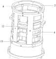
图5是本发明用于失稳航天器的附着式消旋载荷系统的蓄电池组装配图。Fig. 5 is an assembly drawing of the battery pack of the attached racemic load system for unstable spacecraft according to the present invention.
图6是本发明用于失稳航天器的附着式消旋载荷系统的结构主体示意图。Fig. 6 is a schematic diagram of the structural main body of the attached racemic load system for an unstable spacecraft according to the present invention.
图7是本发明用于失稳航天器的附着式消旋载荷系统的支架示意图。Fig. 7 is a schematic diagram of the bracket of the attached racemic load system for an unstable spacecraft according to the present invention.
实施方式Implementation
下面将结合本发明实施例中的附图,对本发明实施例中的技术方案进行清楚、完整地描述,显然,所描述的实施例仅仅是本发明的一部分实施例,而不是全部的实施例。基于本发明中的实施例,本领域普通技术人员在没有创造性劳动前提下所获得的所有其他实施例,都属于本发明保护的范围。The following will clearly and completely describe the technical solutions in the embodiments of the present invention with reference to the accompanying drawings in the embodiments of the present invention. Obviously, the described embodiments are only part of the embodiments of the present invention, not all of them. Based on the embodiments of the present invention, all other embodiments obtained by persons of ordinary skill in the art without creative efforts fall within the protection scope of the present invention.
需要说明,本发明实施例中所有方向性指示(诸如上、下、左、右、前、后……)仅用于解释在某一特定姿态(如附图所示)下各部件之间的相对位置关系、运动情况等,如果该特定姿态发生改变时,则该方向性指示也相应地随之改变。It should be noted that all directional indications (such as up, down, left, right, front, back...) in the embodiments of the present invention are only used to explain the relationship between the components in a certain posture (as shown in the figure). Relative positional relationship, movement conditions, etc., if the specific posture changes, the directional indication will also change accordingly.
另外,在本发明中如涉及“第一”、“第二”等的描述仅用于描述目的,而不能理解为指示或暗示其相对重要性或者隐含指明所指示的技术特征的数量。由此,限定有“第一”、“第二”的特征可以明示或者隐含地包括至少一个该特征。在本发明地描述中,“多个”地含义是至少两个,例如两个、三个等,除非另有明确具体地限定。In addition, in the present invention, descriptions such as "first", "second" and so on are used for description purposes only, and should not be understood as indicating or implying their relative importance or implicitly indicating the quantity of indicated technical features. Thus, the features defined as "first" and "second" may explicitly or implicitly include at least one of these features. In the description of the present invention, "plurality" means at least two, such as two, three, etc., unless otherwise specifically defined.
在本发明中,除非另有明确的规定和限定,术语“连接”、“固定”等应作广义理解,例如,“固定”可以是固定连接,也可以是可拆卸连接,或成一体;“连接”可以是机械连接,也可以是电连接。对于本领域的普通技术人员而言,可以根据具体情况理解上述术语在本发明中的具体含义。In the present invention, unless otherwise specified and limited, the terms "connection" and "fixation" should be interpreted in a broad sense, for example, "fixation" can be a fixed connection, a detachable connection, or an integral body; " "Connection" may be a mechanical connection or an electrical connection. Those of ordinary skill in the art can understand the specific meanings of the above terms in the present invention according to specific situations.
另外,本发明各个实施例之间的技术方案可以相互结合,但是必须是以本领域普通技术人员能够实现为基础,当技术方案的结合出现相互矛盾或无法实现时应当认为这种技术方案的结合不存在,也不在本发明要求的保护范围指内。In addition, the technical solutions of the various embodiments of the present invention can be combined with each other, but it must be based on the realization of those skilled in the art. When the combination of technical solutions is contradictory or cannot be realized, it should be considered as a combination of technical solutions. Does not exist, nor is it within the protection scope of the present invention.
下面将结合本设计实例对具体实施方式、以及本次发明的技术难点、发明点进行进一步介绍。The specific implementation, technical difficulties and invention points of this invention will be further introduced below in conjunction with this design example.
本发明的捕获对象主要为姿控系统故障、部分元器件损坏的失稳卫星及空间碎片。对空间非合作目标的捕获可以应用在许多空间任务中,例如对未成功入轨的卫星进行辅助入轨,对故障卫星更换仪器元件,对燃料耗尽卫星补加燃料,对未正常展开太阳能帆板或天线进行辅助展开,以及空间碎片捕获或一些军事任务,具有极为重要的军民两用价值。The captured objects of the present invention are mainly unstable satellites and space debris with faults in the attitude control system and damaged parts of components. The capture of space non-cooperative targets can be applied in many space missions, such as assisting satellites that have not successfully entered orbit, replacing instrument components for faulty satellites, refueling satellites that have run out of fuel, and refueling satellites that have not been deployed normally. Auxiliary deployment of boards or antennas, as well as space debris capture or some military tasks, have extremely important military and civilian dual-use values.
如图1所示,本发明所述的用于失稳航天器的附着式消旋载荷系统,包括主承力框2、综合电子系统3、蓄电池组4、冷气微推力器5、固体火箭推力器6、安装板7、外壳15和若干飞矛1,主承力框2顶面固连有安装板7,若干飞矛1均匀分布在安装板7上,综合电子系统3和蓄电池组4自上而下依次设置在主承力框2内,冷气微推力器5固定在主承力框2底面,固体火箭推力器6固定在冷气微推力器5底面;外壳15环绕主承力框2和冷气微推力器5外壁设置,包裹综合电子系统3、蓄电池组4和冷气微推力器5,主承力框2、冷气微推力器5、固体火箭推力器6均为回转体;综合电子系统3分别与蓄电池组4、冷气微推力器5、固体火箭推力器6连接。As shown in Fig. 1, the attached type derotation load system for unstable spacecraft according to the present invention comprises a main bearing
进一步地,结合图2,所述飞矛1与主承力框2之间通过一块5mm厚的安装板7和隔震垫安装,通过螺钉将矛固定在安装板7上,安装板7通过侧面的螺钉安装于主承力框1顶部。安装板7可将飞矛1侵彻的冲击力均匀分散到主承力框2边缘,减小冲击对载荷结构的影响。Further, referring to Fig. 2, the
进一步地,结合图5,所述综合电子系统3置于主承力框2内部,pcb板通过安装支架8固定于主承力框2上,蓄电池组4与主承力框2之间无刚性连接,通过顶部端盖12和底部端盖13固定位置,端盖12与主承力框2通过螺钉固定,蓄电池组4与主承力框2和端盖12之间通过隔震垫缓冲,减小发射和侵彻目标时的冲击蓄电池焊点的影响。Further, referring to FIG. 5 , the integrated
所述安装支架8由固定环和若干支撑柱构成,若干支撑柱环绕固定环底面均匀分布,支撑柱固定在主承力框2内壁,综合电子系统3通过支撑柱支撑固定。The
所述综合电子系统3包括第一pcb板9、第二pcb板10和第三pcb板11,所述第一pcb板9为CPU板,第二pcb板10为微推板,第三pcb板11为UV通信板,三块pcb板平行间隔套在若干支撑柱上,第一pcb板9分别与第二pcb板10、第三pcb板11、蓄电池组4和固体火箭推力器6连接,第二pcb板10再与冷气微推力器5连接。The integrated
进一步地,结合图6,所述主承力框2和冷气微推力器5作为结构主体,需要承受载荷发射和侵彻目标时的冲击,因此设计冷气微推力器5底部与主承力框2底部进行面接触,冲击力均匀分布于接触面,减小形变,冷气微推力器5与主承力框2通过侧面的螺钉进行定位。Further, in combination with Fig. 6, the main load-bearing
进一步地,结合图6和图7,所述冷气微推力器5与固体火箭推力器6之间通过支架14安装,所述支架14由安装板和固定在安装板底面的支撑筒构成。固体火箭推力器6通过螺钉固定在支撑筒上,安装板与冷气微推力器5底部的支柱通过螺钉固连。Further, referring to Fig. 6 and Fig. 7, the cold air micro thruster 5 and the
进一步地,所述载荷主体即主承力框2和冷气微推力器5通过侧面的螺钉与外壳15进行连接,外壳15底部镂空部分与固体火箭推力器6药柱部分配合。外壳15与结构主体之间留有3mm间隙,用于隔热材料的安装。Further, the load body, namely the main load-bearing
进一步地,所述固体火箭推力器喷管伸出在外壳15,采用无后座发射技术,避免固体火箭推力器6瞬时冲击对试验飞行器造成的姿态扰动甚至翻转。Further, the nozzle of the solid rocket thruster protrudes from the
进一步地,将所述冷气微推力器5和主承力框2作为结构主体,所有部件以结构主体为基准对称安装,以此减小任务过程中推理偏心造成的影响。Further, the cold air micro-thruster 5 and the main load-bearing
进一步地,所述外壳15环绕主承力框2和冷气微推力器5外壁设置,包裹综合电子系统3、蓄电池组4和冷气微推力器5,主承力框2上部伸出外壳15,以此减小外壳体积,达到减重的目的。Further, the
进一步地,所述综合电子系统3用于实现对载荷的任务管理、能源管理、姿态控制以及信号收发等功能。Further, the integrated
工作过程:work process:
S1、服务航天器携带消旋载荷搭载火箭发射入轨。S1. The service spacecraft is launched into orbit with a derotation payload on board a rocket.
S2、基于空间在轨维修救援的应用场景,服务卫星携带消旋载荷抵近至失稳航天器附近。S2. Based on the application scenario of on-orbit maintenance and rescue in space, the service satellite carries the derotation load and approaches the unstable spacecraft.
S3、服务卫星对失稳航天器进行三维重构和特征识别,辨识出可附着区域。S3. The service satellite performs three-dimensional reconstruction and feature recognition on the unstable spacecraft, and identifies the attachable area.
S4、由于失稳航天器处于自旋状态,服务航天器需等待发射时机,发射时机来临,服务航天器给出分离信号,固体火箭推力器6工作,消旋载荷发射。S4. Since the unstable spacecraft is in a spin state, the service spacecraft needs to wait for the launch opportunity. When the launch opportunity arrives, the service spacecraft sends a separation signal, the
S5、消旋载荷通过初始速度和飞矛1对失稳目标进行侵彻和锚定,之后基于自身携带的陀螺仪对目标质量特性以及附着位置进行辨识,随后综合电子系统3控制冷气微推力器5对失稳航天器进行消旋控制。S5. The derotation load penetrates and anchors the unstable target through the initial velocity and the flying
Claims (3)
Translated fromChinesePriority Applications (1)
| Application Number | Priority Date | Filing Date | Title |
|---|---|---|---|
| CN202210519460.XACN114802811B (en) | 2022-05-13 | 2022-05-13 | Attached racemization load system for unsteady spacecraft |
Applications Claiming Priority (1)
| Application Number | Priority Date | Filing Date | Title |
|---|---|---|---|
| CN202210519460.XACN114802811B (en) | 2022-05-13 | 2022-05-13 | Attached racemization load system for unsteady spacecraft |
Publications (2)
| Publication Number | Publication Date |
|---|---|
| CN114802811A CN114802811A (en) | 2022-07-29 |
| CN114802811Btrue CN114802811B (en) | 2023-05-05 |
Family
ID=82513619
Family Applications (1)
| Application Number | Title | Priority Date | Filing Date |
|---|---|---|---|
| CN202210519460.XAActiveCN114802811B (en) | 2022-05-13 | 2022-05-13 | Attached racemization load system for unsteady spacecraft |
Country Status (1)
| Country | Link |
|---|---|
| CN (1) | CN114802811B (en) |
Families Citing this family (2)
| Publication number | Priority date | Publication date | Assignee | Title |
|---|---|---|---|---|
| CN115402536B (en)* | 2022-08-19 | 2023-04-07 | 南京理工大学 | Rapid racemization electric heating jet type micro-propulsion system for space instability target |
| CN116039973B (en)* | 2023-01-10 | 2024-04-23 | 南京理工大学 | Distributed rope hook structure and rope net capturing device |
Family Cites Families (6)
| Publication number | Priority date | Publication date | Assignee | Title |
|---|---|---|---|---|
| CN105841556B (en)* | 2016-02-25 | 2017-04-12 | 湖北航天技术研究院总体设计所 | General advanced upper stage of solid launch vehicle |
| CN106114919B (en)* | 2016-08-01 | 2018-08-10 | 北京理工大学 | A kind of space junk rope system pulls racemization and method for cleaning |
| CN106467178B (en)* | 2016-09-19 | 2018-11-02 | 哈尔滨工业大学 | Whisker adhesion type large-size space non-cooperative target rapid racemization processing bag |
| CN110040264B (en)* | 2019-05-14 | 2022-10-25 | 西北工业大学 | An integrated device for racemization and capture |
| CN112173171A (en)* | 2019-07-04 | 2021-01-05 | 南京理工大学 | High-integration-level three-unit cube satellite capable of being mechanically transferred into orbit |
| GR1010151B (en)* | 2020-04-07 | 2022-01-17 | Ελληνικη Τεχνολογια Ρομποτικης Αβεε, | System for satellite docking for extension of its useful life, or for orbit modification, including satellite de-orbiting and associated method for satellite docking |
- 2022
- 2022-05-13CNCN202210519460.XApatent/CN114802811B/enactiveActive
Also Published As
| Publication number | Publication date |
|---|---|
| CN114802811A (en) | 2022-07-29 |
Similar Documents
| Publication | Publication Date | Title |
|---|---|---|
| JP7100780B2 (en) | Service satellites for providing orbital services with variable thruster control | |
| US11708181B2 (en) | Methods and apparatus for performing propulsion operations using electric propulsion systems | |
| CN114802811B (en) | Attached racemization load system for unsteady spacecraft | |
| CN108482711B (en) | Method and apparatus for performing propulsion operations using an electric propulsion system | |
| CA2820943C (en) | Spacecraft propellant tank mount | |
| CN112777001B (en) | Micro-nano satellite accompanied with orbit entering | |
| Wang et al. | Design and application prospect of China’s Tiangong Space Station | |
| CN109927936B (en) | Static orbit satellite with load isolated from platform thermal deformation | |
| CN110356592A (en) | It is a kind of based on an arrow double star from series connection radiation pattern full electricity push away satellite platform configuration | |
| JP7344358B2 (en) | Debris removal satellite, debris removal control device, debris removal control method, and ground equipment | |
| CN112141364A (en) | Reusable earth-moon transportation system and method | |
| US20240101280A1 (en) | Method and device for capture of tumbling space objects | |
| WO2022132669A1 (en) | System and devices for high altitidue atmospheric payload transportation and deployment | |
| CN104290918B (en) | Miniaturization track towboat satellite configuration and layout design method | |
| Bui et al. | Design and Development of AOBA VELOX-IV nanosatellite for future Lunar Horizon Glow mission | |
| CN117508644A (en) | Method, device, system and equipment for transporting goods between earth and moon | |
| CN109774986B (en) | A magnetic levitation cube aerostat | |
| Vaughan | Gimbal development for the next ion propulsion system | |
| RU2795894C1 (en) | Serving satellite for orbital services using variable engine control | |
| RU210165U1 (en) | Universal space platform for small spacecraft | |
| RU2772500C2 (en) | Serving satellite for orbital services using variable engine control | |
| CN118372986A (en) | Mother satellite and son-mother satellite assembly | |
| Lindberg et al. | Pegasus air-launched space booster | |
| CN117302550A (en) | Multi-star serial transmitting system | |
| CN117068390A (en) | On-orbit reconfigurable modularized satellite |
Legal Events
| Date | Code | Title | Description |
|---|---|---|---|
| PB01 | Publication | ||
| PB01 | Publication | ||
| SE01 | Entry into force of request for substantive examination | ||
| SE01 | Entry into force of request for substantive examination | ||
| GR01 | Patent grant | ||
| GR01 | Patent grant |