CN114800519A - Six-degree-of-freedom industrial robot dynamics parameter identification method considering friction - Google Patents
Six-degree-of-freedom industrial robot dynamics parameter identification method considering frictionDownload PDFInfo
- Publication number
- CN114800519A CN114800519ACN202210551540.3ACN202210551540ACN114800519ACN 114800519 ACN114800519 ACN 114800519ACN 202210551540 ACN202210551540 ACN 202210551540ACN 114800519 ACN114800519 ACN 114800519A
- Authority
- CN
- China
- Prior art keywords
- degree
- industrial robot
- joint
- freedom industrial
- freedom
- Prior art date
- Legal status (The legal status is an assumption and is not a legal conclusion. Google has not performed a legal analysis and makes no representation as to the accuracy of the status listed.)
- Granted
Links
- 238000000034methodMethods0.000titleclaimsabstractdescription23
- 230000001133accelerationEffects0.000claimsabstractdescription25
- 230000005284excitationEffects0.000claimsabstractdescription15
- 238000004422calculation algorithmMethods0.000claimsabstractdescription12
- 238000005457optimizationMethods0.000claimsabstractdescription12
- 239000011159matrix materialSubstances0.000claimsdescription46
- 238000005070samplingMethods0.000claimsdescription10
- 238000013461designMethods0.000claimsdescription7
- 238000006073displacement reactionMethods0.000claimsdescription4
- 230000005484gravityEffects0.000claimsdescription3
- 241000283973Oryctolagus cuniculusSpecies0.000description11
- 230000008569processEffects0.000description6
- 238000004364calculation methodMethods0.000description4
- 230000003068static effectEffects0.000description4
- 238000009795derivationMethods0.000description3
- 230000007123defenseEffects0.000description2
- 238000011161developmentMethods0.000description2
- 230000000694effectsEffects0.000description2
- 230000000750progressive effectEffects0.000description2
- 230000008521reorganizationEffects0.000description2
- 238000011160researchMethods0.000description2
- 230000009286beneficial effectEffects0.000description1
- 239000012141concentrateSubstances0.000description1
- 238000010276constructionMethods0.000description1
- 230000002596correlated effectEffects0.000description1
- 230000000875corresponding effectEffects0.000description1
- 230000008878couplingEffects0.000description1
- 238000010168coupling processMethods0.000description1
- 238000005859coupling reactionMethods0.000description1
- 238000000354decomposition reactionMethods0.000description1
- 230000007812deficiencyEffects0.000description1
- 238000002474experimental methodMethods0.000description1
- 230000008676importEffects0.000description1
- 230000006872improvementEffects0.000description1
- 238000012986modificationMethods0.000description1
- 230000004048modificationEffects0.000description1
- 238000005381potential energyMethods0.000description1
- 230000006798recombinationEffects0.000description1
- 238000005215recombinationMethods0.000description1
- 230000009897systematic effectEffects0.000description1
- 238000012795verificationMethods0.000description1
Images


Classifications
- B—PERFORMING OPERATIONS; TRANSPORTING
- B25—HAND TOOLS; PORTABLE POWER-DRIVEN TOOLS; MANIPULATORS
- B25J—MANIPULATORS; CHAMBERS PROVIDED WITH MANIPULATION DEVICES
- B25J9/00—Programme-controlled manipulators
- B25J9/16—Programme controls
- B25J9/1628—Programme controls characterised by the control loop
- B25J9/1633—Programme controls characterised by the control loop compliant, force, torque control, e.g. combined with position control
- B—PERFORMING OPERATIONS; TRANSPORTING
- B25—HAND TOOLS; PORTABLE POWER-DRIVEN TOOLS; MANIPULATORS
- B25J—MANIPULATORS; CHAMBERS PROVIDED WITH MANIPULATION DEVICES
- B25J9/00—Programme-controlled manipulators
- B25J9/16—Programme controls
- B25J9/1656—Programme controls characterised by programming, planning systems for manipulators
- B25J9/1661—Programme controls characterised by programming, planning systems for manipulators characterised by task planning, object-oriented languages
- B—PERFORMING OPERATIONS; TRANSPORTING
- B25—HAND TOOLS; PORTABLE POWER-DRIVEN TOOLS; MANIPULATORS
- B25J—MANIPULATORS; CHAMBERS PROVIDED WITH MANIPULATION DEVICES
- B25J9/00—Programme-controlled manipulators
- B25J9/16—Programme controls
- B25J9/1656—Programme controls characterised by programming, planning systems for manipulators
- B25J9/1664—Programme controls characterised by programming, planning systems for manipulators characterised by motion, path, trajectory planning
Landscapes
- Engineering & Computer Science (AREA)
- Robotics (AREA)
- Mechanical Engineering (AREA)
- Feedback Control In General (AREA)
Abstract
Translated fromChineseDescription
Translated fromChinese技术领域technical field
本发明涉及机器人动力学领域,特别涉及一种考虑摩擦的六自由度工业机器人动力学参数辨识方法。The invention relates to the field of robot dynamics, in particular to a dynamic parameter identification method for a six-degree-of-freedom industrial robot considering friction.
背景技术Background technique
随着工业机器人向高速度化、高精度化、智能化、数字化方向发展,提升机器人的运动性能和控制品质显得尤为重要。机器人系统具有多输入多输出、强耦合、非线性以及时变等特点,并且,工业机器人负载惯量大、存在非线性摩擦、不确定性扰动以及机械装配误差等因素影响其运动性能,基于动力学的控制更需要精确的模型,而构建准确的摩擦力模型对提升动力学模型精度具有重要作用。获取机器人动力学模型参数的有效方法主要是进行机器人动力学辨识实验。With the development of industrial robots in the direction of high speed, high precision, intelligence and digitization, it is particularly important to improve the motion performance and control quality of robots. The robot system has the characteristics of multiple input and multiple output, strong coupling, nonlinearity and time variation, and the industrial robot has large load inertia, nonlinear friction, uncertain disturbance and mechanical assembly error and other factors that affect its motion performance. The control of the friction force requires an accurate model, and the construction of an accurate friction force model plays an important role in improving the accuracy of the dynamic model. The most effective way to obtain the parameters of the robot dynamics model is to carry out the robot dynamics identification experiment.
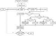
动力学参数辨识的主要步骤是建立动力学模型、进行参数线性化与重组、设计激励轨迹及优化参数、采集与处理实验数据、设计参数辨识算法、进行模型验证,具体流程如图1所示。建立动力学模型的主要方法有牛顿-欧拉法、拉格朗日法、凯恩方法和旋量理论等。现有的摩擦模型包含静态摩擦模型和动态摩擦模型。静态摩擦模型参数的辨识需在高精度低速跟踪条件下进行。而动态摩擦模型虽能较好描述摩擦在低速时的特性,但往往是不连续的或者分段连续的。其次,激励轨迹的设计影响辨识参数的可信度。目前工业机器人动力学参数辨识大都采用傅里叶级数型的轨迹,但是,傅里叶级数不满足速度、加速度的边界条件,容易在轨迹起点和终点产生加速度突变,引起机器人振颤,不利于机器人平稳跟踪,影响辨识精度。在辨识算法上,传统的最小二乘法进行参数估计精度不高,且部分参数不符合物理可行性。The main steps of dynamic parameter identification are to establish a dynamic model, perform parameter linearization and reorganization, design excitation trajectory and optimize parameters, collect and process experimental data, design parameter identification algorithm, and conduct model verification. The specific process is shown in Figure 1. The main methods for establishing dynamic models include Newton-Euler method, Lagrange method, Kane method and spinor theory. The existing friction models include static friction models and dynamic friction models. The identification of static friction model parameters needs to be carried out under the condition of high-precision and low-speed tracking. The dynamic friction model can describe the characteristics of friction at low speed, but it is often discontinuous or continuous in segments. Secondly, the design of the excitation trajectory affects the reliability of the identification parameters. At present, the dynamic parameter identification of industrial robots mostly adopts the Fourier series trajectory. However, the Fourier series does not meet the boundary conditions of speed and acceleration, and it is easy to produce sudden acceleration changes at the start and end points of the trajectory, causing the robot to vibrate. It is beneficial to the stable tracking of the robot and affects the identification accuracy. In the identification algorithm, the traditional least squares method has low parameter estimation accuracy, and some parameters do not meet the physical feasibility.
发明内容SUMMARY OF THE INVENTION
本发明的目的在于克服上述不足,提供一种可以提高辨识精度、改善辨识效果的考虑摩擦的六自由度工业机器人动力学参数辨识方法。The purpose of the present invention is to overcome the above deficiencies, and to provide a dynamic parameter identification method for a six-degree-of-freedom industrial robot that can improve the identification accuracy and improve the identification effect, considering friction.
本发明的一种考虑摩擦的六自由度工业机器人动力学参数辨识方法,包括以下步骤:A method for identifying dynamic parameters of a six-degree-of-freedom industrial robot considering friction of the present invention includes the following steps:
步骤一、建立考虑摩擦的六自由度工业机器人动力学模型,动力学方程表示如下:

其中


步骤二、对六自由度工业机器人动力学模型进行线性化和参数重组,得到如下公式:Step 2: Linearize and reorganize the dynamic model of the six-degree-of-freedom industrial robot, and obtain the following formula:

其中,Kmin为六自由度工业机器人待辨识的最小动力学参数集,包含六自由度工业机器人各连杆基本惯性参数和各关节摩擦系数,
步骤三、采用基于傅里叶级数展开的Freudenstein 1-3-5模型Step 3. Use the Freudenstein 1-3-5 model based on Fourier series expansion
设计并优化六自由度工业机器人各个关节的激励轨迹,Freudenstein 1-3-5模型中边界条件设定为:Design and optimize the excitation trajectory of each joint of the six-degree-of-freedom industrial robot. The boundary conditions in the Freudenstein 1-3-5 model are set as:


步骤四、采集六自由度工业机器人的各个关节的位置信息q和各个关节的驱动电流im,计算六自由度工业机器人的各个关节的速度


第一步,在机器人控制器中完成对步骤三获取的六自由度工业机器人各个关节的激励轨迹速度规划与插补,将插补后的六自由度工业机器人各个关节的激励轨迹输入到机器人驱动器中,驱动机器人关节转动;The first step is to complete the speed planning and interpolation of the excitation trajectory of each joint of the 6-DOF industrial robot obtained in step 3 in the robot controller, and input the interpolated excitation trajectory of each joint of the 6-DOF industrial robot to the robot driver. , drive the robot joints to rotate;
第二步,在六自由度工业机器人按激励轨迹运行过程中采集六自由度工业机器人的各个关节的位置信息q和各个关节的驱动电流im,生成各个关节的位置曲线和驱动电流曲线,然后对位置曲线和驱动电流进行平滑滤波;The second step is to collect the position information q of each joint of the six-degree-of-freedom industrial robot and the driving current im of each joint during the operation of the six-degree-of-freedom industrial robot according to the excitationtrajectory , and generate the position curve and driving current curve of each joint, and then Smooth and filter the position curve and drive current;
第三步,对滤波后的关节位置曲线拟合为改进的傅里叶级数,然后,对改进的傅里叶级数进行微分获得六自由度工业机器人的各个关节的速度

第四步,各个关节的采样力矩τc用下式估计得到:In the fourth step, the sampling moment τc of each joint is estimated by the following formula:
τc=kaimτc =ka im
ka为驱动电机转矩常数;ka is the torque constant of the drive motor;
第五步,将本步骤第三步获得的六自由度工业机器人的各个关节的位置q、速度


步骤五、选用基于改进的哈里斯鹰优化算法进行动力学参数辨识,对公式
本发明使用连续可微的摩擦模型、利用基于傅里叶级数展开的弗洛伊德斯坦(Freudenstein)1-3-5轨迹、使用改进的哈里斯鹰(MHHO)智能优化算法确定动力学参数,能一次辨识所有动力学参数,提高了辨识效率和精度。The present invention uses a continuously differentiable friction model, uses the Freudenstein 1-3-5 trajectory based on Fourier series expansion, and uses the improved Harris Hawk (MHHO) intelligent optimization algorithm to determine the dynamic parameters , which can identify all dynamic parameters at one time, which improves the identification efficiency and accuracy.
附图说明Description of drawings
图1六自由度工业机器人动力学模型参数辨识流程图;Fig. 1 The flow chart of parameter identification of the dynamic model of the six-degree-of-freedom industrial robot;
图2 Makkar摩擦模型曲线图;Fig. 2 Makkar friction model curve;
图3哈里斯鹰优化算法流程图。Figure 3. Flowchart of the Harris Eagle optimization algorithm.
具体实施方式Detailed ways
下面结合附图和实施例对本发明加以详细说明。The present invention will be described in detail below with reference to the accompanying drawings and embodiments.
如附图所示的本发明的一种考虑摩擦的六自由度工业机器人动力学参数辨识方法,包括以下步骤:As shown in the accompanying drawings, a method for identifying the dynamic parameters of a six-degree-of-freedom industrial robot considering friction of the present invention includes the following steps:
步骤一、建立考虑摩擦的六自由度工业机器人动力学模型,动力学方程表示如下:

其中,


具体地,specifically,
q=[q1,q2,……,qn]Tq=[q1 ,q2 ,...,qn ]T


G(q)=[g1,g2,……,gn]TG(q)=[g1 ,g2 ,...,gn ]T

式中,qn为第n个关节的位移,mnn为第n个关节的加速度


其中

其中,γi∈R,i=1,2…6为未知正常数。


本动力学方程的推导过程如下:The derivation process of this dynamic equation is as follows:
第一步,给定六自由度工业机器人型号及参数,根据改进的D-H参数法建立六自由度工业机器人运动学模型,得到六自由度工业机器人的雅可比矩阵J和旋转矩阵TR;The first step, given the model and parameters of the six-degree-of-freedom industrial robot, establish a kinematic model of the six-degree-of-freedom industrial robot according to the improved DH parameter method, and obtain the Jacobian matrix J and the rotation matrix TR of the six-degree-of-freedom industrial robot;
第二步,使用拉格朗日法对六自由度工业机器人进行动力学建模,过程为:首先,按照《机器人学导论》(机械工业出版社,2006)中关于绘制机器人的连杆模型原则建立六自由度工业机器人连杆模型,在连杆模型上定义六自由度工业机器人的广义坐标系,在连杆模型上选定独立的广义关节变量q及对应的广义力τ;The second step is to use the Lagrangian method to model the dynamics of a six-degree-of-freedom industrial robot. Establish a six-degree-of-freedom industrial robot linkage model, define the generalized coordinate system of the six-degree-of-freedom industrial robot on the linkage model, and select an independent generalized joint variable q and the corresponding generalized force τ on the linkage model;
第三步,将六自由度工业机器人系统的拉格朗日函数


第四步,对拉格朗日函数

整理可得机器人动力学方程:Arrange the available robot dynamics equations:

步骤二、对六自由度工业机器人动力学模型进行线性化和参数重组,得到如下公式:Step 2: Linearize and reorganize the dynamic model of the six-degree-of-freedom industrial robot, and obtain the following formula:

其中,Kmin为六自由度工业机器人待辨识的最小动力学参数集,包含六自由度工业机器人各连杆基本惯性参数和各关节摩擦系数,
本步骤具体过程如下:The specific process of this step is as follows:
第一步,将六自由度工业机器人动力学模型导入数学计算软件(如可以采用Matlab符号计算工具箱或者软件Symoro中编程获得)中;The first step is to import the dynamic model of the six-degree-of-freedom industrial robot into the mathematical calculation software (for example, it can be obtained by using the Matlab symbolic calculation toolbox or the software Symoro);
第二步,对六自由度工业机器人动力学模型中除

其中,
ki=[mi,mirxi,miryi,mirzi,Ixxi,Ixyi,Ixzi,Iyyi,Iyzi,Izzi]Tki =[mi ,mi rxi ,mi ryi ,mi rzi ,Ixxi ,Ixyi ,Ixzi ,Iyyi ,Iyzi ,Izzi ]T
式中,ki∈R10,为六自由度工业机器人惯性参数,mi为第i根连杆的质量,rxi、ryi、rzi分别为第i根连杆的质心在六自由度工业机器人的广义坐标系下的x、y、z轴分坐标,mirxi、miryi、mirzi分别为第i根连杆关于x、y、z轴的一阶质量矩。Ixxi、Ixyi、Ixzi为第i根连杆绕x轴对x轴、y轴、z轴产生的惯性矩,Iyyi、Iyzi为第i根连杆绕y轴对y轴、z轴产生的惯性矩,Izzi为第i根连杆绕z轴对z轴产生的惯性矩。In the formula, ki ∈ R10 , is the inertial parameter of the six-degree-of-freedom industrial robot, mi is the mass of the ith connecting rod, rxi , ryyi , and rzi are the center of mass of the ith connecting rod in the six-degree-of-freedom The sub-coordinates of the x, y, and z axes in the generalized coordinate system of the industrial robot, mi rxi , mi ryi , and mi rzi are the first-order mass moments of the i-th connecting rod about the x, y, and z axes, respectively . Ixxi , Ixyi , and Ixzi are the moments of inertia generated by the i-th connecting rod around the x-axis to the x-axis, y-axis, and z-axis, and Iyyi and Iyzi are the i-th connecting rod around the y-axis to the y-axis, z-axis The moment of inertia generated by the axis, Izzi is the moment of inertia generated by the i-th connecting rod around the z-axis to the z-axis.
第三步,对


对
根据对机器人摩擦特性的研究结果可获知γ2,γ3,γ5取值,为已知值,γ2,γ3,γ5分别为105.8、10.0、93.6。因此,摩擦力矩向量

第四步,动力学方程全部线性化为:In the fourth step, the kinetic equations are all linearized as:

式中,


γi1、γi2、γi3、γi4、γi5、γi6为第i关节受到的摩擦力矩
第五步,由于回归矩阵


步骤三、采用基于傅里叶级数展开的弗洛伊德斯坦Freudenstein 1-3-5模型(具体参见Biagiotti,L.,&Melchiorri,C.(2008).Trajectory planning for automaticmachines and robots.比亚乔蒂,L.,&梅尔奇奥里,C.(2008)。《自动机械和机器人的轨迹规划》)设计并优化六自由度工业机器人各个关节的激励轨迹,Freudenstein 1-3-5模型中边界条件设定为:Step 3. Adopt the Freudenstein 1-3-5 model based on Fourier series expansion (for details, see Biagiotti, L., & Melchiorri, C. (2008). Trajectory planning for automatic machines and robots. Piaggio Ti, L., & Melchiori, C. (2008. Trajectory Planning for Automatic Machinery and Robots) Designing and optimizing the excitation trajectories of each joint of a six-degree-of-freedom industrial robot, in the Freudenstein 1-3-5 model The boundary conditions are set as:


步骤四、采集六自由度工业机器人的各个关节的位置信息q和各个关节的驱动电流im,计算六自由度工业机器人的各个关节的速度


第一步,在机器人控制器中完成对步骤三获取的六自由度工业机器人各个关节的激励轨迹速度规划与插补,将插补后的六自由度工业机器人各个关节的激励轨迹输入到机器人驱动器中,驱动机器人关节转动。The first step is to complete the speed planning and interpolation of the excitation trajectory of each joint of the 6-DOF industrial robot obtained in step 3 in the robot controller, and input the interpolated excitation trajectory of each joint of the 6-DOF industrial robot to the robot driver. , drive the robot joints to rotate.
第二步,在六自由度工业机器人按激励轨迹运行过程中采集六自由度工业机器人的各个关节的位置信息q和各个关节的驱动电流im,生成各个关节的位置曲线和驱动电流曲线,然后对位置曲线和驱动电流进行平滑滤波;The second step is to collect the position information q of each joint of the six-degree-of-freedom industrial robot and the driving current im of each joint during the operation of the six-degree-of-freedom industrial robot according to the excitationtrajectory , and generate the position curve and driving current curve of each joint, and then Smooth and filter the position curve and drive current;
第三步,对滤波后的关节位置曲线拟合为改进的傅里叶级数,然后,对改进的傅里叶级数进行微分获得六自由度工业机器人的各个关节的速度

本步骤中对收集到的位置曲线和电流曲线可以采用Savitzky-Golay滤波器进行平滑滤波。In this step, the collected position curve and current curve can be smoothed by using a Savitzky-Golay filter.
第四步,各个关节的采样力矩τc可用下式估计得到:In the fourth step, the sampling moment τc of each joint can be estimated by the following formula:
τc=kaimτc =ka im
ka为驱动电机转矩常数,通过电机手册查找可知。ka is the torque constant of the drive motor, which can be known from the motor manual.
第五步,将本步骤第三步获得的六自由度工业机器人的各个关节的位置q、速度


步骤五、选用基于改进的哈里斯鹰优化算法(MHHO)(具体参见刘骏鹏.哈里斯鹰算法的改进及应用研究[D].浙江大学,2021.)进行动力学参数辨识,对公式

该算法可以在Matlab中编程实现。如图3所示,作为本发明的一种实施方式,Kmin的求解过程如下:The algorithm can be programmed in Matlab. As shown in Figure 3, as an embodiment of the present invention, the solution process of Kmin is as follows:
第一步,将改进的哈里斯鹰优化算法(MHHO)编程写入Matlab程序,步骤如下:The first step is to program the improved Harris Hawk optimization algorithm (MHHO) into a Matlab program. The steps are as follows:
设定哈里斯鹰种群的参数,然后对哈里斯鹰种群初始化得到每一只哈里斯鹰的初始位置,参数包括种群数量η、优化问题维度d以及最大迭代次数T;Set the parameters of the Harris eagle population, and then initialize the Harris eagle population to obtain the initial position of each Harris eagle. The parameters include the population number η, the optimization problem dimension d and the maximum number of iterations T;
哈里斯鹰种群El=(X1,X2,...,Xη)T,哈里斯鹰初始位置矩阵

其中,d为优化问题维度,Xη,d表示第η只哈里斯鹰第d个维度,最小动力学参数集Kmin为d×1维矩阵,将最小动力学参数集Kmin中的d各元素依次代入上式得到待优化的初始位置矩阵
第二步,将哈里斯鹰优化算法中适应度函数编程写入Matlab程序;The second step is to write the fitness function programming in the Harris Eagle optimization algorithm into the Matlab program;
适用度函数F(X)表述如下:The fitness function F(X) is expressed as follows:

适用度函数F(X)中的元素f(x)计算式如下:The element f(x) in the fitness function F(X) is calculated as follows:

其中,m为采样次数,τc为机器人各关节采样力矩,τ为机器人各关节理论力矩,x为哈里斯鹰初始位置矩阵
第三步,在程序中调整哈里斯鹰的种群位置个体位置并更新兔子位置与逃逸能量。根据调整后种群的新位置,依次遍历每个兔子个体的适应度值(在本例中,适应度值越低意味着适应度值越优),找出哈里斯鹰最佳适应度值,并且每次迭代都需要更新兔子的逃逸能量,能量是一个在-2到2之间变化的值,随着迭代次数增加而自适应衰减,哈里斯鹰能够根据兔子猎物的能量进行策略选择。The third step is to adjust the population position of the Harris eagle and update the position and escape energy of the rabbit in the program. According to the new position of the adjusted population, traverse the fitness value of each individual rabbit in turn (in this case, the lower the fitness value means the better the fitness value), to find the best fitness value of Harris Hawk, and The escape energy of the rabbit needs to be updated in each iteration. The energy is a value that varies between -2 and 2, and it adaptively decays with the increase of the number of iterations. Harris Hawk can choose a strategy according to the energy of the rabbit prey.
步骤501,计算兔子当前的逃逸能量E。Step 501: Calculate the current escape energy E of the rabbit.

其中,t为当前迭代次数,E0为(-1,1)之间的随机数;Among them, t is the current iteration number, and E0 is a random number between (-1, 1);
步骤502,判断E的大小,若|E|≥1,则执行步骤503,若|E|<1则执行步骤504。Step 502, determine the size of E, if |E|≥1, execute step 503, and if |E|<1, execute step 504.
步骤503,哈里斯鹰进行全局搜索,寻找兔子。根据发现或未发现兔子,随机产生数σ,并得到下述搜索公式:Step 503, Harris Hawk performs a global search to find rabbits. According to whether the rabbit is found or not, the number σ is randomly generated, and the following search formula is obtained:

其中,X(t+1)表示下次迭代时哈里斯鹰的位置向量,Xr(t)是兔子的位置向量,Xrand(t)表示鹰群的随机个体的位置向量,UB和LB为优化问题维度的上限、下限,X(t)为该鹰的当前位置向量,r1,r2,r3,r4和σ为(0,1)之间的随机数,Xm(t)是哈里斯鹰种群的当前平均位置,计算公式如下:Among them, X(t+1) represents the position vector of the Harris eagle in the next iteration, Xr (t) is the position vector of the rabbit, Xrand (t) represents the position vector of the random individual of the eagle group, UB and LB are The upper and lower limits of the dimension of the optimization problem, X(t) is the current position vector of the eagle, r1 , r2 , r3 , r4 and σ are random numbers between (0, 1), Xm (t) is the current average position of the Harris Hawk population, calculated as:

Xρ(t)表示第t次迭代时每只哈里斯鹰的位置。Xρ (t) represents the position of each Harris Hawk at the t-th iteration.
步骤504,当0<|E|<1时,哈里斯鹰进行局部搜索,用μ<0.5表示兔子逃脱成功,μ≥0.5表示兔子逃脱失败;然后判断E的绝对值是否小于0.5,μ是否小于0.5。若0.5≤|E|<1、μ≥0.5,则执行步骤505,否则执行步骤506。若0<|E|<0.5、μ≥0.5,则执行步骤507,否则执行步骤508。Step 504, when 0<|E|<1, Harris Eagle performs a local search, using μ<0.5 to indicate that the rabbit escaped successfully, and μ≥0.5 to indicate that the rabbit failed to escape; then it is judged whether the absolute value of E is less than 0.5 and whether μ is less than 0.5. If 0.5≤|E|<1 and μ≥0.5, go to step 505, otherwise go to step 506. If 0<|E|<0.5 and μ≥0.5, go to step 507, otherwise go to step 508.
步骤505,当0.5≤|E|<1、μ≥0.5时,哈里斯鹰执行盘旋围捕策略,哈里斯鹰位置向量更新如下:Step 505, when 0.5≤|E|<1, μ≥0.5, Harris Eagle executes the circling and rounding strategy, and the Harris Eagle position vector is updated as follows:
X(t+1)=△X(t)-E|JXr(t)-X(t)|X(t+1)=△X(t)-E|JXr (t)-X(t)|
△X(t)=Xr(t)-X(T)△X(t)=Xr (t)-X(T)
其中,△X(t)为当前迭代次数为t时哈里斯鹰与兔子的位置之差,随机数J∈(0,2)。Among them, △X(t) is the difference between the positions of the Harris Hawk and the rabbit when the current iteration number is t, and the random number J∈(0,2).
步骤506,当0.5≤|E|<1、μ<0.5时,哈里斯鹰执行盘旋围捕与渐进俯冲攻击策略,哈里斯鹰位置向量更新如下:Step 506, when 0.5≤|E|<1, μ<0.5, the Harris Hawk executes the strategy of circling round-up and progressive dive attack, and the Harris Hawk position vector is updated as follows:

其中,S为d维优化问题随机行向量,矩阵Y=Xr(t)-E|JXr(t)-X(t)|,矩阵Z=Y+S×LF(d),将矩阵Y、Z、X(t)代入步骤五第二步中的适用度函数F(X)中,从而求得F(Y)、F(X(t))、F(Z),LF(d)为调用的Matlab中飞行函数。Among them, S is the random row vector of the d-dimensional optimization problem, the matrix Y=Xr (t)-E|JXr (t)-X(t)|, the matrix Z=Y+S×LF(d), the matrix Y , Z, X(t) are substituted into the fitness function F(X) in the second step of step 5, so as to obtain F(Y), F(X(t)), F(Z), LF(d) is Call the flight function in Matlab.
步骤507,当0<|E|<0.5、μ≥0.5时,哈里斯鹰执行强势突袭策略,哈里斯鹰位置向量更新如下:Step 507, when 0<|E|<0.5 and μ≥0.5, Harris Eagle executes a strong raid strategy, and the Harris Eagle position vector is updated as follows:
X(t+1)=Xr(t)-E|△X(t)|X(t+1)=Xr (t)-E|△X(t)|
步骤508,当0<|E|<0.5、μ<0.5时,哈里斯鹰执行强势突袭与渐进俯冲攻击策略,哈里斯鹰位置向量更新如下:Step 508, when 0<|E|<0.5 and μ<0.5, the Harris Eagle executes a strong surprise attack and a progressive dive attack strategy, and the Harris Eagle position vector is updated as follows:

第四步,判断当前迭代次数t是否大于或者等于最大迭代次数T或者达到迭代精度,如果是,则输出当前哈里斯鹰位置矩阵,即为所需辨识动力学参数Kmin,否则,搜索继续。The fourth step is to judge whether the current number of iterations t is greater than or equal to the maximum number of iterations T or reach the iteration accuracy. If so, output the current Harris Eagle position matrix, which is the required identification dynamic parameter Kmin , otherwise, the search continues.
以上对本发明的描述仅仅是示意性的,而不是限制性的,所以,本发明的实施方式并不局限于上述的具体实施方式。如果本领域的普通技术人员受其启示,在不脱离本发明宗旨和权利要求所保护范围的情况下,做出其他变化或变型,均属于本发明的保护范围。The above description of the present invention is only illustrative rather than restrictive, and therefore, the embodiments of the present invention are not limited to the specific embodiments described above. If those of ordinary skill in the art are enlightened by it, without departing from the spirit of the present invention and the protection scope of the claims, other changes or modifications are made, which all belong to the protection scope of the present invention.
Claims (1)
Translated fromChinese


Priority Applications (1)
| Application Number | Priority Date | Filing Date | Title |
|---|---|---|---|
| CN202210551540.3ACN114800519B (en) | 2022-05-20 | 2022-05-20 | Six-degree-of-freedom industrial robot dynamic parameter identification method considering friction |
Applications Claiming Priority (1)
| Application Number | Priority Date | Filing Date | Title |
|---|---|---|---|
| CN202210551540.3ACN114800519B (en) | 2022-05-20 | 2022-05-20 | Six-degree-of-freedom industrial robot dynamic parameter identification method considering friction |
Publications (2)
| Publication Number | Publication Date |
|---|---|
| CN114800519Atrue CN114800519A (en) | 2022-07-29 |
| CN114800519B CN114800519B (en) | 2023-09-26 |
Family
ID=82517167
Family Applications (1)
| Application Number | Title | Priority Date | Filing Date |
|---|---|---|---|
| CN202210551540.3AActiveCN114800519B (en) | 2022-05-20 | 2022-05-20 | Six-degree-of-freedom industrial robot dynamic parameter identification method considering friction |
Country Status (1)
| Country | Link |
|---|---|
| CN (1) | CN114800519B (en) |
Cited By (3)
| Publication number | Priority date | Publication date | Assignee | Title |
|---|---|---|---|---|
| CN117415817A (en)* | 2023-11-22 | 2024-01-19 | 哈尔滨工业大学 | A method for identifying robot joint torque constants based on current level dynamics |
| CN117549300A (en)* | 2023-11-22 | 2024-02-13 | 哈尔滨工业大学 | A method to identify the dynamic parameters of a robotic arm at the current level |
| CN120422245B (en)* | 2025-06-25 | 2025-09-09 | 山东大学 | A robot dynamic parameter identification method, system, device and medium |
Citations (7)
| Publication number | Priority date | Publication date | Assignee | Title |
|---|---|---|---|---|
| JP2002283276A (en)* | 2001-03-21 | 2002-10-03 | Daihen Corp | Collision detecting-stopping control method in articulated robot |
| CN101726296A (en)* | 2009-12-22 | 2010-06-09 | 哈尔滨工业大学 | Vision measurement, path planning and GNC integrated simulation system for space robot |
| CN107498562A (en)* | 2017-04-21 | 2017-12-22 | 浙江工业大学 | Six-degree-of-freedom mechanical arm dynamics model identification method |
| CN110058523A (en)* | 2019-04-29 | 2019-07-26 | 杭州亿恒科技有限公司 | SCARA Identification of Dynamic Parameters of Amanipulator method based on Maximum-likelihood estimation |
| CN111267105A (en)* | 2020-03-18 | 2020-06-12 | 无锡砺成智能装备有限公司 | Kinetic parameter identification and collision detection method for six-joint robot |
| WO2020133270A1 (en)* | 2018-12-28 | 2020-07-02 | 深圳配天智能技术研究院有限公司 | Dynamic parameter identification method for robot, robot and storage device |
| CN112074248A (en)* | 2018-04-27 | 2020-12-11 | 爱尔康公司 | Three-dimensional visual camera and integrated robot technology platform |
- 2022
- 2022-05-20CNCN202210551540.3Apatent/CN114800519B/enactiveActive
Patent Citations (7)
| Publication number | Priority date | Publication date | Assignee | Title |
|---|---|---|---|---|
| JP2002283276A (en)* | 2001-03-21 | 2002-10-03 | Daihen Corp | Collision detecting-stopping control method in articulated robot |
| CN101726296A (en)* | 2009-12-22 | 2010-06-09 | 哈尔滨工业大学 | Vision measurement, path planning and GNC integrated simulation system for space robot |
| CN107498562A (en)* | 2017-04-21 | 2017-12-22 | 浙江工业大学 | Six-degree-of-freedom mechanical arm dynamics model identification method |
| CN112074248A (en)* | 2018-04-27 | 2020-12-11 | 爱尔康公司 | Three-dimensional visual camera and integrated robot technology platform |
| WO2020133270A1 (en)* | 2018-12-28 | 2020-07-02 | 深圳配天智能技术研究院有限公司 | Dynamic parameter identification method for robot, robot and storage device |
| CN110058523A (en)* | 2019-04-29 | 2019-07-26 | 杭州亿恒科技有限公司 | SCARA Identification of Dynamic Parameters of Amanipulator method based on Maximum-likelihood estimation |
| CN111267105A (en)* | 2020-03-18 | 2020-06-12 | 无锡砺成智能装备有限公司 | Kinetic parameter identification and collision detection method for six-joint robot |
Non-Patent Citations (1)
| Title |
|---|
| 吴文祥;朱世强;靳兴来;: "基于改进傅里叶级数的机器人动力学参数辨识", 浙江大学学报(工学版), no. 02* |
Cited By (3)
| Publication number | Priority date | Publication date | Assignee | Title |
|---|---|---|---|---|
| CN117415817A (en)* | 2023-11-22 | 2024-01-19 | 哈尔滨工业大学 | A method for identifying robot joint torque constants based on current level dynamics |
| CN117549300A (en)* | 2023-11-22 | 2024-02-13 | 哈尔滨工业大学 | A method to identify the dynamic parameters of a robotic arm at the current level |
| CN120422245B (en)* | 2025-06-25 | 2025-09-09 | 山东大学 | A robot dynamic parameter identification method, system, device and medium |
Also Published As
| Publication number | Publication date |
|---|---|
| CN114800519B (en) | 2023-09-26 |
Similar Documents
| Publication | Publication Date | Title |
|---|---|---|
| CN114800519A (en) | Six-degree-of-freedom industrial robot dynamics parameter identification method considering friction | |
| CN105159096B (en) | A kind of redundancy space manipulator joint moment optimization method based on particle cluster algorithm | |
| CN109514602B (en) | Industrial robot moment compensation control method based on load self-adaptive identification | |
| CN106393116B (en) | Mechanical arm fractional order iterative learning control method with Initial state learning and system | |
| CN104950677B (en) | Mechanical arm system saturation compensation control method based on back-stepping sliding mode control | |
| CN105772917B (en) | A kind of three joint spot welding robot's Trajectory Tracking Control methods | |
| CN114571444B (en) | A Q-learning-based impedance control method for a slag removal robot | |
| CN108527372A (en) | A kind of joint of robot self-adaptation control method of variation rigidity series elastic driver | |
| CN112894821B (en) | Method, device and equipment for dragging and teaching control of collaborative robot based on current method | |
| CN109676610A (en) | A kind of breaker puts together machines people and its method of realizing working trajectory optimization | |
| CN116038681B (en) | Method and device for identifying dynamic parameters of manipulator based on parameter separation | |
| CN104950678A (en) | Neural network inversion control method for flexible manipulator system | |
| CN116000936B (en) | Industrial robot self-adaptive impedance control method, equipment and medium based on state transition algorithm | |
| CN110842911B (en) | Flexible mechanical arm combined modeling and sliding mode control method considering joint motor characteristics | |
| CN107037726B (en) | It is a kind of non-with first new fractional-order system synovial membrane interference observer design method | |
| CN115157250A (en) | A dynamic parameter identification method for a seven-degree-of-freedom manipulator | |
| CN114859725A (en) | A nonlinear system adaptive event-triggered control method and system | |
| CN104965413B (en) | The friciton compensation self-adaptation control method of controlledization flat pad | |
| CN117325178A (en) | Flexible mechanical arm control method and system based on fractional order complementary sliding mode | |
| CN114967441B (en) | A networked nonholonomically constrained multi-robot grouping consistent tracking control method, micro-control unit and control system | |
| CN119858164A (en) | Control method and system of flexible joint robot under input delay | |
| CN107263455B (en) | The Position Tracking Control method of two degrees of freedom SCARA robot | |
| CN116619351B (en) | Design method of interval observer of mechanical arm system based on event trigger mechanism | |
| CN118170016A (en) | Kinetic parameter identification method and system for processing inconsistency of joint measurement | |
| CN114952825B (en) | Method, equipment and storage medium for realizing Lagrange system group consensus |
Legal Events
| Date | Code | Title | Description |
|---|---|---|---|
| PB01 | Publication | ||
| PB01 | Publication | ||
| SE01 | Entry into force of request for substantive examination | ||
| SE01 | Entry into force of request for substantive examination | ||
| GR01 | Patent grant | ||
| GR01 | Patent grant |