CN114800371A - Ejection tool - Google Patents
Ejection toolDownload PDFInfo
- Publication number
- CN114800371A CN114800371ACN202110064623.5ACN202110064623ACN114800371ACN 114800371 ACN114800371 ACN 114800371ACN 202110064623 ACN202110064623 ACN 202110064623ACN 114800371 ACN114800371 ACN 114800371A
- Authority
- CN
- China
- Prior art keywords
- ejector
- threaded
- hole
- support
- threaded member
- Prior art date
- Legal status (The legal status is an assumption and is not a legal conclusion. Google has not performed a legal analysis and makes no representation as to the accuracy of the status listed.)
- Pending
Links
- 238000009434installationMethods0.000description6
- 238000000034methodMethods0.000description5
- 238000010586diagramMethods0.000description1
- 230000000694effectsEffects0.000description1
- 238000012986modificationMethods0.000description1
- 230000004048modificationEffects0.000description1
Images
Classifications
- B—PERFORMING OPERATIONS; TRANSPORTING
- B25—HAND TOOLS; PORTABLE POWER-DRIVEN TOOLS; MANIPULATORS
- B25B—TOOLS OR BENCH DEVICES NOT OTHERWISE PROVIDED FOR, FOR FASTENING, CONNECTING, DISENGAGING OR HOLDING
- B25B27/00—Hand tools, specially adapted for fitting together or separating parts or objects whether or not involving some deformation, not otherwise provided for
- B25B27/02—Hand tools, specially adapted for fitting together or separating parts or objects whether or not involving some deformation, not otherwise provided for for connecting objects by press fit or detaching same
- B25B27/10—Hand tools, specially adapted for fitting together or separating parts or objects whether or not involving some deformation, not otherwise provided for for connecting objects by press fit or detaching same inserting fittings into hoses
Landscapes
- Engineering & Computer Science (AREA)
- Mechanical Engineering (AREA)
- Automatic Assembly (AREA)
Abstract
Translated fromChinese
Description
Translated fromChinese技术领域technical field
本发明涉及零件拆卸技术领域,特别涉及一种顶出工具。The invention relates to the technical field of parts disassembly, in particular to an ejector tool.
背景技术Background technique
现有技术中,发动机的碗型塞是通过过盈配合压装到缸盖的安装孔上,难以拆卸。具体如下:In the prior art, the bowl plug of the engine is press-fitted to the mounting hole of the cylinder head through an interference fit, which is difficult to disassemble. details as follows:
1、如果出现碗型塞压不到位或碗型塞压装后出现其它质量问题时,碗型塞就无法拆下来,则会导致整台缸盖报废。1. If the bowl-shaped plug is not pressed in place or other quality problems occur after the bowl-shaped plug is pressed, the bowl-shaped plug cannot be removed, which will cause the entire cylinder head to be scrapped.
2、而如果采用暴力拆卸,则会破坏碗型塞及缸盖上气门座圈孔等重要加工表面,导致缸盖报废。2. If violent disassembly is used, the important machined surfaces such as the bowl plug and the valve seat ring hole on the cylinder head will be damaged, resulting in the scrapping of the cylinder head.
发明内容SUMMARY OF THE INVENTION
本发明提供一种顶出工具,用于至少解决上述一个技术问题。The present invention provides an ejector tool for solving at least one of the above-mentioned technical problems.
本发明的顶出工具,包括:顶出件、支撑件和调节组件,所述顶出件和所述支撑件分别设置在待拆工件的两侧,并且所述顶出件和所述支撑件通过所述调节组件相连,所述调节组件带动所述顶出件向靠近所述支撑件的方向移动,以使所述顶出件顶出所述待拆工件。The ejector tool of the present invention includes: an ejector, a support and an adjustment assembly, the ejector and the support are respectively arranged on both sides of the workpiece to be disassembled, and the ejector and the support are Connected by the adjusting assembly, the adjusting assembly drives the ejector to move toward the direction close to the support, so that the ejector ejects the workpiece to be disassembled.
在一个实施方式中,所述调节组件包括:第一螺纹件和第二螺纹件,其中,所述第一螺纹件和/或所述第二螺纹件限位式连接于所述支撑件上,所述第一螺纹件的端部和所述第二螺纹件的端部分别穿过所述支撑件与所述顶出件的相应的侧部螺纹连接,通过转动所述第一螺纹件和所述第二螺纹件能够带动所述顶出件向靠近所述支撑件的方向移动。In one embodiment, the adjustment assembly includes: a first screw member and a second screw member, wherein the first screw member and/or the second screw member are connected to the support member in a limiting manner, The end of the first threaded member and the end of the second threaded member are respectively threaded through the support member with the corresponding side portions of the ejector, and by rotating the first threaded member and all The second screw member can drive the ejection member to move in a direction close to the support member.
在一个实施方式中,所述支撑件上设置设有第一通孔和第二通孔,所述第一螺纹件和所述第二螺纹件分别对应地设置于所述第一通孔和所述第二通孔中,并且所述第一螺纹件的外壁与所述第一通孔的孔壁之间有间距,所述第二螺纹件的外壁与所述第二通孔的孔壁之间有间距。In one embodiment, the support member is provided with a first through hole and a second through hole, and the first threaded member and the second threaded member are respectively correspondingly disposed in the first through hole and the second through hole. In the second through hole, and there is a distance between the outer wall of the first threaded member and the hole wall of the first through hole, the outer wall of the second threaded member and the hole wall of the second through hole are spaced apart. There is space between.
在一个实施方式中,所述第一螺纹件通过限位螺母限位式连接于所述支撑件上,其中,所述限位螺母螺纹连接于所述第一螺纹件上,并且所述限位螺母的底面与所述支撑件的远离所述顶出件的一侧相抵。In one embodiment, the first threaded member is limitedly connected to the support member through a limit nut, wherein the limit nut is threadedly connected to the first threaded member, and the limit The bottom surface of the nut abuts against the side of the support member away from the ejector member.
在一个实施方式中,所述顶出件的两侧部上分别设置有贯通的第一螺纹孔和第二螺纹孔,所述第一螺纹件的端部和所述第二螺纹件的端部分别螺纹连接于所述第一螺纹孔和所述第二螺纹孔中。In one embodiment, a first threaded hole and a second threaded hole are respectively provided on both sides of the ejector, and the end of the first threaded member and the end of the second threaded member They are respectively screwed into the first threaded hole and the second threaded hole.
在一个实施方式中,所述第一螺纹件和所述第二螺纹件的头部均设置有拧紧孔。In one embodiment, the heads of the first threaded member and the second threaded member are provided with tightening holes.
在一个实施方式中,所述调节组件包括:调节螺杆和螺纹连接在调节螺杆上的调节螺母,其中,所述调节螺杆的端部穿过所述支撑件与所述顶出件可拆卸相连,所述调节螺母的底面与所述支撑件的远离所述顶出件的一侧相抵,通过转动所述调节螺母使所述调节螺杆沿与所述支撑件垂直的方向移动,从而带动所述顶出件向靠近所述支撑件的方向移动。In one embodiment, the adjustment assembly includes: an adjustment screw and an adjustment nut threaded on the adjustment screw, wherein the end of the adjustment screw is detachably connected to the ejector through the support member, The bottom surface of the adjusting nut is in contact with the side of the supporting piece away from the ejecting piece, and by rotating the adjusting nut, the adjusting screw is moved in a direction perpendicular to the supporting piece, thereby driving the ejecting piece. The outgoing piece moves toward the direction close to the support piece.
在一个实施方式中,所述顶出件包括:第一压板和设置在所述第一压板上的顶杆,其中,所述述第一压板的延伸方向与所述顶杆的延伸方向垂直,所述第一压板通过所述调节组件与所述支撑件相连,所述顶杆用于顶出所述待拆工件。In one embodiment, the ejector includes: a first pressing plate and an ejector rod disposed on the first pressing plate, wherein the extending direction of the first pressing plate is perpendicular to the extending direction of the ejecting rod, The first pressing plate is connected to the supporting member through the adjusting assembly, and the ejector rod is used to eject the workpiece to be disassembled.
在一个实施方式中,所述第一压板的中部设有第三螺纹孔,所述顶杆的端部设置有螺纹,所述顶杆的端部螺纹连接于所述第三螺纹孔中。In one embodiment, a third threaded hole is provided in the middle of the first pressing plate, a thread is provided at the end of the ejector rod, and the end of the ejector pin is threadedly connected to the third threaded hole.
在一个实施方式中,所述支撑件为第二压板,所述第二压板上设置有与所述待拆工件位置相对应的顶出孔。In one embodiment, the support member is a second pressing plate, and the second pressing plate is provided with an ejection hole corresponding to the position of the workpiece to be disassembled.
与现有技术相比,本发明的优点在于:本发明中,通过调节组件带动顶出件向靠近支撑件的方向移动,以将待拆工件慢慢顶出,从而实现了工件的拆卸,尤其适用于过盈装配的工件的拆卸,代替了暴力拆卸,可避免对被拆卸部位造成额外的损坏。本发明的顶出工具,结构简单,使用方便,能够降低拆卸所需要的时间,提高拆卸效率。Compared with the prior art, the advantages of the present invention are: in the present invention, the ejector is driven to move in the direction close to the support by the adjusting assembly, so as to slowly eject the workpiece to be disassembled, thereby realizing the disassembly of the workpiece, especially It is suitable for the disassembly of workpieces with interference assembly, instead of violent disassembly, which can avoid additional damage to the disassembled parts. The ejecting tool of the invention has simple structure and convenient use, can reduce the time required for disassembly, and improve the disassembly efficiency.
附图说明Description of drawings
在下文中将基于实施例并参考附图来对本发明进行更详细的描述。In the following the invention will be described in more detail on the basis of examples and with reference to the accompanying drawings.
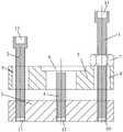
图1是本发明的一个实施例的顶出工具的结构示意图;1 is a schematic structural diagram of an ejector tool according to an embodiment of the present invention;
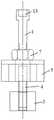
图2是本发明的一个实施例的顶出工具的侧视图。Figure 2 is a side view of an ejector tool according to one embodiment of the present invention.
附图标记:Reference number:
1-第一螺纹件;2-第二螺纹件;3-第一压板;4-顶杆;5-第二压板;1- the first screw; 2- the second screw; 3- the first pressure plate; 4- the ejector rod; 5- the second pressure plate;
6-顶出孔;7-限位螺母;8-第一通孔;9-第二通孔;10-第一螺纹孔;6-Ejection hole; 7-Limiting nut; 8-First through hole; 9-Second through hole; 10-First threaded hole;
11-第二螺纹孔;12-第三螺纹孔;13-拧紧孔。11-Second threaded hole; 12-Third threaded hole; 13-Tightening hole.
具体实施方式Detailed ways
下面将结合附图对本发明作进一步说明。The present invention will be further described below with reference to the accompanying drawings.
如图1-2中所示,本发明提供一种顶出工具,适用于过盈装配的工件的拆卸,尤其适用于缸盖上的碗形塞等圆形工件的拆卸。As shown in Figs. 1-2, the present invention provides an ejector tool, which is suitable for the disassembly of workpieces fitted with interference, and is especially suitable for the disassembly of circular workpieces such as bowl-shaped plugs on cylinder heads.
本发明的顶出工具包括:顶出件、支撑件和调节组件,顶出件和支撑件分别设置在待拆工件的两侧,并且顶出件和支撑件通过调节组件相连,调节组件带动顶出件向靠近支撑件的方向移动,以使顶出件顶出待拆工件。The ejector tool of the present invention includes: an ejector, a support and an adjustment assembly, the ejector and the support are respectively arranged on both sides of the workpiece to be disassembled, and the ejector and the support are connected through the adjustment assembly, and the adjustment assembly drives the ejector The ejector moves toward the direction close to the support, so that the ejector ejects the workpiece to be dismantled.
本发明中,通过调节组件带动顶出件向靠近支撑件的方向移动,以将待拆工件慢慢顶出,从而实现了工件的拆卸,尤其适用于过盈装配的工件的拆卸,代替了暴力拆卸,可避免对被拆卸部位造成额外的损坏。In the present invention, the adjusting component drives the ejector to move in the direction close to the support, so that the workpiece to be disassembled is slowly ejected, thereby realizing the disassembly of the workpiece, which is especially suitable for the disassembly of the workpiece with interference assembly, instead of violent disassembly to avoid additional damage to the part being disassembled.
具体地,支撑件和顶出件均沿第一方向延伸并平行设置,调节组件带动顶出沿第二方向移动以靠近支撑件,其中第一方向与第二方向垂直。例如,第一方向为水平方向,第二方向为垂直方向。Specifically, both the support member and the ejector member extend along a first direction and are arranged in parallel, and the adjusting assembly drives the ejector member to move along a second direction to approach the support member, wherein the first direction is perpendicular to the second direction. For example, the first direction is a horizontal direction, and the second direction is a vertical direction.
本发明的顶出工具,结构简单,使用方便,能够降低拆卸所需要的时间,提高拆卸效率。在使用时,将顶出件放置在待拆工件的下方,将支撑件放置在待拆工件的上方(具体为待拆工件的安装部位的上表面上),再通过调节组件将支撑件和顶出件连接在一起,然后通过调节组件带动顶出件向靠近支撑件的方向(向上)移动,从将待拆工件从其安装部位处顶出。The ejecting tool of the invention has simple structure and convenient use, can reduce the time required for disassembly, and improve the disassembly efficiency. When in use, the ejector is placed under the workpiece to be removed, the support is placed above the workpiece to be removed (specifically, on the upper surface of the installation part of the workpiece to be removed), and then the support and the ejector are moved through the adjustment assembly. The ejection pieces are connected together, and then the ejection piece is driven by the adjusting assembly to move toward the direction (upward) close to the support piece, so as to eject the workpiece to be disassembled from its installation position.
此外,本发明的调节组件不包含电气或液压等驱动部件,结构简单,占用空间小。In addition, the adjusting assembly of the present invention does not include electric or hydraulic driving components, has a simple structure, and occupies a small space.
在一个实施例中,调节组件包括:第一螺纹件1和第二螺纹件2,其中,第一螺纹件1和/或第二螺纹件2限位式连接于支撑件上,第一螺纹件1的端部和第二螺纹件2的端部分别穿过支撑件与顶出件的相应的侧部螺纹连接,通过转动第一螺纹件1和第二螺纹件2能够带动顶出件向靠近支撑件的方向移动。In one embodiment, the adjustment assembly includes: a first threaded
具体地,支撑件和顶出件沿水平方向延伸,第一螺纹件1和第二螺纹件2沿垂直方向延伸,第一螺纹件1的端部和第二螺纹件2的端部分别穿过支撑件与顶出件的相应的侧部螺纹连接,换言之,第一螺纹件1与第二螺纹件2未与支撑件之间形成螺纹连接,支撑件用于安装并对调节组件起到限位的作用。Specifically, the support member and the ejection member extend in the horizontal direction, the
在本实施例中,第一螺纹件1和第二螺纹件2与顶出件形成一个类似丝杠的结构,可将旋转运动转化成直线运动。这样,在转动第一螺纹件1和第二螺纹件2时,由于第一螺纹件1和/或第二螺纹件2限位式连接在支撑件上,第一螺纹件1和第二螺纹件2与支撑件的相对位置不会发生变化,即第一螺纹件1和第二螺纹件2转动时,其不能在第二方向移动,从而使顶出件沿着第一螺纹件1和第二螺纹件2向靠近支撑件的方向直线运动,以顶出待拆工件。In this embodiment, the first threaded
并且,通过设置第一螺纹件1和第二螺纹件2两个螺纹件与顶出件螺纹连接,用于限制顶出件以其中一个螺纹件为轴旋转,从而在转动第一螺纹件1和第二螺纹件2时,能够将扭紧力传递至顶出件,带动其沿直线运动。In addition, by setting the first threaded
需要说明的是,顶出待拆工件时,需同时转动第一螺纹件1和第二螺纹件2。It should be noted that, when the workpiece to be disassembled is ejected, the first threaded
优选地,上述第一螺纹件1和第二螺纹件2均为螺栓。Preferably, the first threaded
具体地,支撑件上设置设有第一通孔8和第二通孔9,第一螺纹件1和第二螺纹件2分别对应地设置于第一通孔8和第二通孔9中,并且第一螺纹件1的外壁与第一通孔8的孔壁之间有间距,第二螺纹件2的外壁与第二通孔9的孔壁之间有间距。换言之,支撑件上分别设置第一通孔8和第二通孔9用于穿设第一螺纹件1与第二螺纹件2,并且使其之间未形成螺纹连接,从而转动第一螺纹件1和第二螺纹件2时,支撑件的位置不变。Specifically, the support member is provided with a first through
进一步具体地,第一螺纹件1通过限位螺母7限位式连接于支撑件上,其中,限位螺母7螺纹连接于第一螺纹件1上,并且限位螺母7的底面与支撑件的远离顶出件的一侧相抵。More specifically, the first threaded
需要说明的是,限位螺母7也可以设置在第二螺纹件2上,由于第一螺纹件1和第二螺纹件2通过顶出件连接在一起,则仅在其中一个螺纹件上设置限位螺母7即可实现对两个螺纹件的限位式连接功能。It should be noted that the
在本实施例中,调节组件(第一螺纹件1和第二螺纹件2)的一端通过螺纹与顶出件连接,其另一端则通过限位螺母7与支撑件相连。换言之,限位螺母7作为限位件和连接件,使第一螺纹件1、第二螺纹件2以及顶出件连接在支撑件上,并且在未转动第一螺纹件1和第二螺纹件2时,第一螺纹件1、第二螺纹件2、顶出件和支撑件四者的位置固定。同时,限位螺母7可直接螺纹连接于第一螺纹件1上,安装方便。In this embodiment, one end of the adjusting assembly (the first threaded
具体地,顶出件的两侧部上分别设置有贯通的第一螺纹孔10和第二螺纹孔11,第一螺纹件1的端部和第二螺纹件2的端部分别螺纹连接于第一螺纹孔10和第二螺纹孔11中。从而实现顶出件与第一螺纹件1和第二螺纹件2之间的螺纹连接。Specifically, a first threaded
具体地,第一螺纹件1和第二螺纹件2的头部均设置有拧紧孔13,用于与拧紧工具相适配。优选地,上述拧紧孔13为内六角孔。Specifically, the heads of the first threaded
在另一个实施例中,调节组件包括:调节螺杆和螺纹连接在调节螺杆上的调节螺母,其中,调节螺杆的端部穿过支撑件与顶出件可拆卸相连,调节螺母的底面与支撑件的远离顶出件的一侧相抵,通过转动调节螺母使调节螺杆沿与支撑件垂直的方向移动,从而带动顶出件向靠近支撑件的方向移动。In another embodiment, the adjustment assembly includes: an adjustment screw and an adjustment nut threaded on the adjustment screw, wherein the end of the adjustment screw is detachably connected to the ejector through the support, and the bottom surface of the adjustment nut is connected to the support The side away from the ejector is pushed against each other, and the adjusting screw is moved in a direction perpendicular to the support by rotating the adjusting nut, thereby driving the ejector to move toward the direction close to the support.
具体地,调节螺杆的端部与顶出件螺纹连接。Specifically, the end of the adjusting screw is screwed with the ejector.
在本实施例中,调节螺杆与顶出件安装在一起后,两者的位置相对固定。而通过转动调节螺母使调节螺杆沿与支撑件垂直的方向移动,从而带动顶出件向靠近支撑件的方向移动,其中,调节螺母与支撑件的位置相对固定,即调节螺母在第二方向(垂直方向)上的位置不变,从而将螺母的旋转运动转化为调节螺杆的直线运动,进而带动顶出件向靠近支撑件的方向移动。In this embodiment, after the adjusting screw and the ejector are installed together, the positions of the two are relatively fixed. By rotating the adjusting nut, the adjusting screw is moved in a direction perpendicular to the support, thereby driving the ejector to move in a direction close to the support, wherein the positions of the adjusting nut and the support are relatively fixed, that is, the adjusting nut is in the second direction ( The position in the vertical direction) remains unchanged, so that the rotary motion of the nut is converted into the linear motion of the adjusting screw, and then the ejector is driven to move toward the direction close to the support.
优选地,上述调节组件还包括:限位螺杆,限位螺杆与调节螺杆分别穿过支撑件的两侧与顶出件的两侧部可拆卸相连。其中,限位螺杆用于防止顶出件的转动,进而防止转动调节螺母时调节螺杆发生转动。Preferably, the above-mentioned adjustment assembly further comprises: a limit screw, the limit screw and the adjustment screw respectively pass through two sides of the support member and are detachably connected to the two sides of the ejection member. Wherein, the limit screw is used to prevent the rotation of the ejector, thereby preventing the rotation of the adjustment screw when the adjustment nut is rotated.
在一个实施例中,顶出件包括:第一压板3和设置在第一压板3上的顶杆4,其中,第一压板3通过调节组件与支撑件相连,顶杆4用于顶出待拆工件。优选地,顶杆4设置在第一压板3的中央,并且顶杆4的延伸方向与第一压板3的延伸方向相互垂直。In one embodiment, the ejector includes: a first
优选地,第一压板3的中部设有第三螺纹孔12,顶杆4的端部设置有螺纹,顶杆4的端部螺纹连接于第三螺纹孔12中。其中,螺纹连接一种可拆卸连接方式,顶杆4的下端安装于第三螺纹孔12中,拆卸和安装方便,并且通过旋转顶杆4可调节其顶端高度,或者更换不同长度的顶杆4,以适应不同安装部位的待拆工件的拆卸。Preferably, the middle of the first
在一个实施例中,支撑件为第二压板5,第二压板5上设置有与待拆工件位置相对应的顶出孔6。第二压板5上开设顶出孔6,以使待拆工件从顶出孔6中被顶出。In one embodiment, the support member is a second
优选地,顶出孔6设置在第二压板5的中央。Preferably, the ejection hole 6 is arranged in the center of the second
本发明还提供一种上述顶出工具的使用方法,包括以下步骤:The present invention also provides a method for using the above-mentioned ejector tool, comprising the following steps:
S1:将顶出件和支撑件分别设置在待拆工件的两侧;S1: the ejector and the support are respectively arranged on both sides of the workpiece to be dismantled;
S2:将顶出件与支撑件通过调节组件连接在一起,并且使顶出件的顶出端与待拆工件相接触;S2: the ejector and the support are connected together through the adjustment assembly, and the ejection end of the ejector is brought into contact with the workpiece to be disassembled;
S3:通过调节组件带动顶出件向靠近支撑件的方向移动,以使顶出件顶出所述待拆工件。S3: The ejector is driven to move toward the direction close to the support by the adjusting assembly, so that the ejector ejects the workpiece to be disassembled.
其中,步骤S3中,通过调节组件带动顶出件向靠近支撑件的方向移动时,使顶出件与支撑件保持平行。Wherein, in step S3, when the ejector member is driven to move in a direction close to the support member by the adjusting assembly, the ejector member and the support member are kept parallel.
在一个实施方式中,步骤S3中,同时转动调节组件中的第一螺纹件1和第二螺纹件2,以带动顶出件向靠近支撑件的方向移动,从而使顶出件顶出所述待拆工件。In one embodiment, in step S3, the first threaded
实施例Example
下面以采用本发明的顶出工具拆卸缸盖上的碗型塞为例进行说明。The following description will be given by using the ejector tool of the present invention to remove the bowl-shaped plug on the cylinder head as an example.
本实施例中的顶出工具,包括:顶出件、支撑件和调节组件。其中,第一压板3和设置在所述第一压板3上的顶杆4;所述支撑件为第二压板5,所述第二压板5上设置有与所述待拆工件位置相对应的顶出孔6;所述调节组件包括:第一螺栓和第二螺栓,第一螺栓的上部设置有限位螺母7,第一螺栓和第二螺栓通过该限位螺母7限位式连接于第二压板5上,第一螺栓和第二螺栓的端部分别与第一压板3的两侧螺纹连接。The ejector tool in this embodiment includes an ejector, a support and an adjustment assembly. Among them, the first
该工具的使用方法,如下:How to use this tool is as follows:
步骤1:通过转动第一螺栓和第二螺栓,将第一压板3从第一螺栓和第二螺栓的端部拆卸下来。Step 1: Remove the
步骤2:将第一压板3和顶杆4放置缸盖的下方,并使顶杆4的顶出端对准碗型塞,将第二压板5放置在缸盖上,并使碗型塞位于顶出孔6中。Step 2: Place the
步骤3:将第一螺栓和第二螺栓的端部穿过第二压板5与第一压板3的两侧相连后,转动第一螺栓和第二螺栓,使第一螺栓和第二螺栓的端部与第一压板3连接在一起。Step 3: After connecting the ends of the first bolt and the second bolt through the
步骤4:转动第一螺栓上的限位螺母7,使第一压板3和第二压板5夹紧缸盖,并且使第一压板3与第二压板5平行。Step 4: Turn the
步骤5:同时转动第一螺栓和第二螺栓,通过持续的拧紧力把碗型塞从缸盖的塞孔中慢慢顶出来。Step 5: Turn the first bolt and the second bolt at the same time, and slowly push the bowl plug out of the plug hole of the cylinder head with continuous tightening force.
通过以上步骤,可将碗型塞顺利从缸盖的塞孔中顶出,并且不会对缸盖已经及其塞孔的孔壁造成损伤。Through the above steps, the bowl-shaped plug can be pushed out of the plug hole of the cylinder head smoothly without causing damage to the cylinder head and the hole wall of the plug hole.
具体地,碗型塞的底部设置有工艺孔,拆卸时,可将顶杆4插入该工艺孔中。Specifically, the bottom of the bowl-shaped plug is provided with a process hole, and when disassembling, the
其中,可通过工具转动第一螺栓和第二螺栓。例如,在第一螺栓和第二螺栓的头部设置内六角形的拧紧孔13,通过内六角扳手与拧紧孔13配合,即可转动第一螺栓和第二螺栓。Wherein, the first bolt and the second bolt can be rotated by a tool. For example, hexagonal inner hexagonal tightening holes 13 are provided on the heads of the first bolt and the second bolt, and the first bolt and the second bolt can be rotated by matching the inner hexagonal wrench with the tightening
在本实施例中,顶出工具仅在缸盖的顶部进行工作,工作中无需翻转及移动缸盖。该顶出工具的结构简单,且使用方便,将顶杆4的顶出端对准碗型塞,然后用内六角扳手同时旋转两根螺栓,即可使顶杆4顶出碗型塞,整个操作仅需一个人即可顺利完成,单个碗型顶出的工作节拍在1分钟以内,效率很高。In this embodiment, the ejector tool only works on the top of the cylinder head, and there is no need to turn and move the cylinder head during the work. The ejector tool has a simple structure and is easy to use. Align the ejection end of the
虽然已经参考优选实施例对本发明进行了描述,但在不脱离本发明的范围的情况下,可以对其进行各种改进并且可以用等效物替换其中的部件。尤其是,只要不存在结构冲突,各个实施例中所提到的各项技术特征均可以任意方式组合起来。本发明并不局限于文中公开的特定实施例,而是包括落入权利要求的范围内的所有技术方案。While the present invention has been described with reference to the preferred embodiments, various modifications may be made and equivalents may be substituted for parts thereof without departing from the scope of the invention. In particular, as long as there is no structural conflict, each technical feature mentioned in each embodiment can be combined in any manner. The present invention is not limited to the specific embodiments disclosed herein, but includes all technical solutions falling within the scope of the claims.
Claims (10)
Translated fromChinesePriority Applications (1)
| Application Number | Priority Date | Filing Date | Title |
|---|---|---|---|
| CN202110064623.5ACN114800371A (en) | 2021-01-18 | 2021-01-18 | Ejection tool |
Applications Claiming Priority (1)
| Application Number | Priority Date | Filing Date | Title |
|---|---|---|---|
| CN202110064623.5ACN114800371A (en) | 2021-01-18 | 2021-01-18 | Ejection tool |
Publications (1)
| Publication Number | Publication Date |
|---|---|
| CN114800371Atrue CN114800371A (en) | 2022-07-29 |
Family
ID=82525093
Family Applications (1)
| Application Number | Title | Priority Date | Filing Date |
|---|---|---|---|
| CN202110064623.5APendingCN114800371A (en) | 2021-01-18 | 2021-01-18 | Ejection tool |
Country Status (1)
| Country | Link |
|---|---|
| CN (1) | CN114800371A (en) |
Citations (9)
| Publication number | Priority date | Publication date | Assignee | Title |
|---|---|---|---|---|
| CN2853270Y (en)* | 2005-12-17 | 2007-01-03 | 江苏罡阳股份有限公司 | Internal-jacking positioning drill clamp |
| US20090070980A1 (en)* | 2007-09-19 | 2009-03-19 | Livesay Richard E | System for servicing machine track and method |
| CN203019309U (en)* | 2012-12-07 | 2013-06-26 | 宜宾海丝特纤维有限责任公司 | Protective type bearing remover |
| CN208575780U (en)* | 2018-06-15 | 2019-03-05 | 河南中烟工业有限责任公司 | A special tool for bearing disassembly |
| CN110936323A (en)* | 2019-12-30 | 2020-03-31 | 广东大鹏液化天然气有限公司 | Hydraulic cylinder connecting piece disassembling tool and disassembling method |
| CN210361129U (en)* | 2019-06-21 | 2020-04-21 | 滕州东方钢帘线有限公司 | Special tool for disassembling motor of typhoon machine |
| CN211992757U (en)* | 2020-04-21 | 2020-11-24 | 神华粤电珠海港煤炭码头有限责任公司 | Chain pin shaft dismounting tool |
| CN212020626U (en)* | 2020-04-26 | 2020-11-27 | 北京福田康明斯发动机有限公司 | Transmission wheel part dismounting tool |
| CN212192984U (en)* | 2020-05-15 | 2020-12-22 | 天津渤海石化有限公司 | A machine pump shaft coupling extracting tool for propane dehydrogenation system propylene device |
- 2021
- 2021-01-18CNCN202110064623.5Apatent/CN114800371A/enactivePending
Patent Citations (9)
| Publication number | Priority date | Publication date | Assignee | Title |
|---|---|---|---|---|
| CN2853270Y (en)* | 2005-12-17 | 2007-01-03 | 江苏罡阳股份有限公司 | Internal-jacking positioning drill clamp |
| US20090070980A1 (en)* | 2007-09-19 | 2009-03-19 | Livesay Richard E | System for servicing machine track and method |
| CN203019309U (en)* | 2012-12-07 | 2013-06-26 | 宜宾海丝特纤维有限责任公司 | Protective type bearing remover |
| CN208575780U (en)* | 2018-06-15 | 2019-03-05 | 河南中烟工业有限责任公司 | A special tool for bearing disassembly |
| CN210361129U (en)* | 2019-06-21 | 2020-04-21 | 滕州东方钢帘线有限公司 | Special tool for disassembling motor of typhoon machine |
| CN110936323A (en)* | 2019-12-30 | 2020-03-31 | 广东大鹏液化天然气有限公司 | Hydraulic cylinder connecting piece disassembling tool and disassembling method |
| CN211992757U (en)* | 2020-04-21 | 2020-11-24 | 神华粤电珠海港煤炭码头有限责任公司 | Chain pin shaft dismounting tool |
| CN212020626U (en)* | 2020-04-26 | 2020-11-27 | 北京福田康明斯发动机有限公司 | Transmission wheel part dismounting tool |
| CN212192984U (en)* | 2020-05-15 | 2020-12-22 | 天津渤海石化有限公司 | A machine pump shaft coupling extracting tool for propane dehydrogenation system propylene device |
Similar Documents
| Publication | Publication Date | Title |
|---|---|---|
| CN201415335Y (en) | Floating clamping tool special for numerical control milling processing of aluminum alloy parts | |
| CN101695815A (en) | Clamp mechanism for processing piston pin hole of compressor | |
| CN204248501U (en) | Camshaft end surface machining apparatus fixture | |
| CN108032106B (en) | Efficient numerical control turning clamp and clamping method | |
| CN110125705A (en) | Marine low speed diesel engine cylinder cover slant hole drilling clamp | |
| CN218799349U (en) | A multi-station drilling device for mechanical parts | |
| CN115338799A (en) | A mechanical clamping jaw device manufactured by a fixed mechanical fixture for mechanical processing | |
| CN114800371A (en) | Ejection tool | |
| CN114700910A (en) | Method for centering rotating equipment | |
| CN111618619A (en) | Wrench positioning clamp and positioning clamping method | |
| CN110695898B (en) | Magnetic telescopic sleeve | |
| CN115475987B (en) | A multifunctional fixture for micro-milling of micro-small parts | |
| CN217019489U (en) | Driven piece chamber boring tool | |
| CN216895289U (en) | A bolt that is easy and quick to remove | |
| CN110948264B (en) | A connecting beam drilling fixture | |
| CN212664924U (en) | A cylinder liner blank cutting fixture | |
| CN108436519A (en) | Drilling jig for bolts | |
| CN212398171U (en) | Inner support positioning limit fixture device | |
| CN210909650U (en) | Fastening clamp device | |
| JP4099766B2 (en) | Easy maintenance gate valve | |
| CN110757381B (en) | Quick assembly disassembly's screw thread fastener | |
| CN106424888B (en) | Process the horizontal planer of longaxones parts endoporus spline | |
| CN206425860U (en) | The disk milling clamper of cylinder head faying face in engine housing | |
| CN223251102U (en) | A clamping tool for processing thin parts | |
| CN222873907U (en) | Auxiliary device for drilling oil inlet and outlet of oil cylinder |
Legal Events
| Date | Code | Title | Description |
|---|---|---|---|
| PB01 | Publication | ||
| PB01 | Publication | ||
| SE01 | Entry into force of request for substantive examination | ||
| SE01 | Entry into force of request for substantive examination | ||
| RJ01 | Rejection of invention patent application after publication | ||
| RJ01 | Rejection of invention patent application after publication | Application publication date:20220729 |