CN114795354A - Surgical stapler with electric and manual functions - Google Patents
Surgical stapler with electric and manual functionsDownload PDFInfo
- Publication number
- CN114795354A CN114795354ACN202210038033.XACN202210038033ACN114795354ACN 114795354 ACN114795354 ACN 114795354ACN 202210038033 ACN202210038033 ACN 202210038033ACN 114795354 ACN114795354 ACN 114795354A
- Authority
- CN
- China
- Prior art keywords
- firing
- screw
- indicator
- assembly
- stapling device
- Prior art date
- Legal status (The legal status is an assumption and is not a legal conclusion. Google has not performed a legal analysis and makes no representation as to the accuracy of the status listed.)
- Pending
Links
Images


Classifications
- A—HUMAN NECESSITIES
- A61—MEDICAL OR VETERINARY SCIENCE; HYGIENE
- A61B—DIAGNOSIS; SURGERY; IDENTIFICATION
- A61B17/00—Surgical instruments, devices or methods
- A61B17/11—Surgical instruments, devices or methods for performing anastomosis; Buttons for anastomosis
- A61B17/115—Staplers for performing anastomosis, e.g. in a single operation
- A61B17/1155—Circular staplers comprising a plurality of staples
- A—HUMAN NECESSITIES
- A61—MEDICAL OR VETERINARY SCIENCE; HYGIENE
- A61B—DIAGNOSIS; SURGERY; IDENTIFICATION
- A61B17/00—Surgical instruments, devices or methods
- A61B17/34—Trocars; Puncturing needles
- A61B17/3494—Trocars; Puncturing needles with safety means for protection against accidental cutting or pricking, e.g. limiting insertion depth, pressure sensors
- A—HUMAN NECESSITIES
- A61—MEDICAL OR VETERINARY SCIENCE; HYGIENE
- A61B—DIAGNOSIS; SURGERY; IDENTIFICATION
- A61B90/00—Instruments, implements or accessories specially adapted for surgery or diagnosis and not covered by any of the groups A61B1/00 - A61B50/00, e.g. for luxation treatment or for protecting wound edges
- A61B90/08—Accessories or related features not otherwise provided for
- A—HUMAN NECESSITIES
- A61—MEDICAL OR VETERINARY SCIENCE; HYGIENE
- A61B—DIAGNOSIS; SURGERY; IDENTIFICATION
- A61B17/00—Surgical instruments, devices or methods
- A61B2017/00017—Electrical control of surgical instruments
- A—HUMAN NECESSITIES
- A61—MEDICAL OR VETERINARY SCIENCE; HYGIENE
- A61B—DIAGNOSIS; SURGERY; IDENTIFICATION
- A61B17/00—Surgical instruments, devices or methods
- A61B2017/00017—Electrical control of surgical instruments
- A61B2017/00115—Electrical control of surgical instruments with audible or visual output
- A—HUMAN NECESSITIES
- A61—MEDICAL OR VETERINARY SCIENCE; HYGIENE
- A61B—DIAGNOSIS; SURGERY; IDENTIFICATION
- A61B17/00—Surgical instruments, devices or methods
- A61B2017/00367—Details of actuation of instruments, e.g. relations between pushing buttons, or the like, and activation of the tool, working tip, or the like
- A61B2017/00398—Details of actuation of instruments, e.g. relations between pushing buttons, or the like, and activation of the tool, working tip, or the like using powered actuators, e.g. stepper motors, solenoids
- A—HUMAN NECESSITIES
- A61—MEDICAL OR VETERINARY SCIENCE; HYGIENE
- A61B—DIAGNOSIS; SURGERY; IDENTIFICATION
- A61B17/00—Surgical instruments, devices or methods
- A61B2017/0046—Surgical instruments, devices or methods with a releasable handle; with handle and operating part separable
- A—HUMAN NECESSITIES
- A61—MEDICAL OR VETERINARY SCIENCE; HYGIENE
- A61B—DIAGNOSIS; SURGERY; IDENTIFICATION
- A61B17/00—Surgical instruments, devices or methods
- A61B2017/00681—Aspects not otherwise provided for
- A61B2017/00734—Aspects not otherwise provided for battery operated
- A—HUMAN NECESSITIES
- A61—MEDICAL OR VETERINARY SCIENCE; HYGIENE
- A61B—DIAGNOSIS; SURGERY; IDENTIFICATION
- A61B17/00—Surgical instruments, devices or methods
- A61B17/11—Surgical instruments, devices or methods for performing anastomosis; Buttons for anastomosis
- A61B2017/1103—Approximator
- A—HUMAN NECESSITIES
- A61—MEDICAL OR VETERINARY SCIENCE; HYGIENE
- A61B—DIAGNOSIS; SURGERY; IDENTIFICATION
- A61B90/00—Instruments, implements or accessories specially adapted for surgery or diagnosis and not covered by any of the groups A61B1/00 - A61B50/00, e.g. for luxation treatment or for protecting wound edges
- A61B90/08—Accessories or related features not otherwise provided for
- A61B2090/0807—Indication means
- A61B2090/0811—Indication means for the position of a particular part of an instrument with respect to the rest of the instrument, e.g. position of the anvil of a stapling instrument
- A—HUMAN NECESSITIES
- A61—MEDICAL OR VETERINARY SCIENCE; HYGIENE
- A61B—DIAGNOSIS; SURGERY; IDENTIFICATION
- A61B2560/00—Constructional details of operational features of apparatus; Accessories for medical measuring apparatus
- A61B2560/02—Operational features
- A61B2560/0204—Operational features of power management
- A61B2560/0214—Operational features of power management of power generation or supply
Landscapes
- Health & Medical Sciences (AREA)
- Life Sciences & Earth Sciences (AREA)
- Surgery (AREA)
- Molecular Biology (AREA)
- Engineering & Computer Science (AREA)
- Biomedical Technology (AREA)
- Heart & Thoracic Surgery (AREA)
- Medical Informatics (AREA)
- Nuclear Medicine, Radiotherapy & Molecular Imaging (AREA)
- Animal Behavior & Ethology (AREA)
- General Health & Medical Sciences (AREA)
- Public Health (AREA)
- Veterinary Medicine (AREA)
- Pathology (AREA)
- Oral & Maxillofacial Surgery (AREA)
- Surgical Instruments (AREA)
Abstract
Description
Translated fromChinese相关申请的交叉引用CROSS-REFERENCE TO RELATED APPLICATIONS
本申请要求2021年1月21日提交的美国临时专利申请第63/140,066号的权益和优先权,所述申请的全部内容以引用的方式并入本文中。This application claims the benefit of and priority to US Provisional Patent Application No. 63/140,066, filed January 21, 2021, the entire contents of which are incorporated herein by reference.
技术领域technical field
本公开大体上涉及外科缝合装置,且更确切地说,涉及用于吻合手术的外科缝合装置。The present disclosure relates generally to surgical stapling devices, and more particularly, to surgical stapling devices for anastomotic procedures.
背景技术Background technique
圆形缝合装置用于执行各种吻合手术,其中两个管状解剖组织结构连接在一起。这些手术包括结直肠圆形吻合术、食管圆形吻合术和减肥圆形吻合术。通常,圆形缝合装置包括将工具组件连接到手柄组件的适配器组件。工具组件包括砧座组件和壳体组件,其可响应于接近机构的致动而相对于彼此移动以夹持砧座组件和壳体组件之间的组织。壳体组件包括钉仓、推钉器和环形刀。钉仓支撑一或多个环形缝钉排,且推钉器可响应于击发机构的致动在钉仓内移动以将缝钉从钉仓弹出到砧座组件中。环形刀定位在环形缝钉排的径向内侧,且可从缩回位置移动到前进位置,以抵靠砧座组件将组织切割或取芯。Circular suturing devices are used to perform various anastomotic procedures in which two tubular anatomical structures are joined together. These procedures include colorectal circular anastomosis, esophageal circular anastomosis, and bariatric circular anastomosis. Typically, a circular suturing device includes an adapter assembly that connects the tool assembly to the handle assembly. The tool assembly includes an anvil assembly and a housing assembly that are movable relative to each other in response to actuation of the approximation mechanism to clamp tissue between the anvil assembly and the housing assembly. The housing assembly includes a staple cartridge, a staple pusher, and a ring knife. The staple cartridge supports one or more annular rows of staples, and the staple pusher is movable within the staple cartridge in response to actuation of the firing mechanism to eject staples from the staple cartridge into the anvil assembly. An annular knife is positioned radially inboard of the row of annular staples and is movable from a retracted position to an advanced position to cut or coring tissue against the anvil assembly.
圆形缝合装置有手动和电动两种配置。通常,电动配置包括位于手柄组件中的一或多个电动机,其驱动接近机构和击发机构以致动缝合装置,且手动配置包括用于致动接近机构的旋钮和用于致动击发机构的击发触发器。两种装置配置各有优点。归因于组件的较高成本,电动缝合装置(或其部分)配置成可重复使用,而归因于较低成本,手动缝合装置配置成一次性的。可重复使用的缝合装置必须进行适当地除菌。The circular suture device is available in both manual and motorized configurations. Typically, motorized configurations include one or more motors located in the handle assembly that drive an access mechanism and a firing mechanism to actuate the stapling device, and manual configurations include a knob for actuating the access mechanism and a firing trigger for actuating the firing mechanism device. Both device configurations have their advantages. Due to the higher cost of the components, the motorized suturing device (or portion thereof) is configured to be reusable, while the manual suturing device is configured to be disposable due to the lower cost. Reusable suturing devices must be properly sterilized.
存在对具有电动和手动缝合装置配置两者的优点且为一次性的圆形缝合装置的持续需要。There is a continuing need for a circular stapling device that has the advantages of both powered and manual stapling device configurations and is disposable.
发明内容SUMMARY OF THE INVENTION
本公开大体上涉及一种用于在患者体内执行吻合手术的外科缝合装置。外科缝合装置包括手柄组件,其包括手动致动的接近机构和机动击发机构。The present disclosure generally relates to a surgical stapling device for performing anastomotic procedures in a patient. The surgical stapling device includes a handle assembly that includes a manually actuated access mechanism and a motorized firing mechanism.
本公开的各方面涉及一种外科缝合装置,其包括手柄组件、细长主体、砧座保持器和工具组件。细长主体具有远端部分和近端部分。砧座保持器从细长主体的远端部分延伸。工具组件支撑在细长主体的远端部分上,且包括砧座组件和壳体组件。砧座组件具有环形缝钉成形表面,且壳体组件具有环形钉仓。砧座组件耦合到砧座保持器,且可随砧座保持器移动以使工具组件在打开位置与夹持位置之间移动,在打开位置中,砧座组件的环形缝钉成形表面与壳体组件的环形钉仓间隔开,在夹持位置中,砧座组件的环形缝钉成形表面与壳体组件的环形钉仓并列相对。壳体组件还包括推钉器和环形刀,其可相对于环形钉仓在缩回位置与前进位置之间移动,以将缝钉从环形钉仓中弹出且切割组织。手柄组件包括主体部分、手动操作的接近机构和机动击发机构。接近机构耦合到砧座保持器且可手动操作以将砧座保持器缩回到壳体组件中,以将工具组件从打开位置移动到夹持位置。击发机构包括电动机,启动电动机以使推钉器和环形刀在其缩回位置与前进位置之间移动。Aspects of the present disclosure relate to a surgical stapling device that includes a handle assembly, an elongated body, an anvil holder, and a tool assembly. The elongated body has a distal portion and a proximal portion. An anvil holder extends from the distal portion of the elongated body. A tool assembly is supported on the distal portion of the elongated body and includes an anvil assembly and a housing assembly. The anvil assembly has an annular staple forming surface, and the housing assembly has an annular staple cartridge. The anvil assembly is coupled to the anvil holder and is movable with the anvil holder to move the tool assembly between an open position and a clamping position in which the annular staple forming surface of the anvil assembly and the housing are The annular staple cartridges of the assembly are spaced apart, and in the clamped position, the annular staple forming surface of the anvil assembly is juxtaposed against the annular staple cartridge of the housing assembly. The housing assembly also includes a staple pusher and an annular knife moveable relative to the annular staple cartridge between a retracted position and an advanced position to eject staples from the annular staple cartridge and cut tissue. The handle assembly includes a body portion, a manually operated access mechanism, and a motorized firing mechanism. An access mechanism is coupled to the anvil holder and is manually operable to retract the anvil holder into the housing assembly to move the tool assembly from the open position to the gripping position. The firing mechanism includes a motor that is actuated to move the nail pusher and ring knife between its retracted and advanced positions.
在本公开的各方面中,手柄组件的主体部分支撑电池组,其包括通过电路系统电耦合到电动机的一或多个电池。In aspects of the present disclosure, the body portion of the handle assembly supports a battery pack that includes one or more batteries electrically coupled to the motor through circuitry.
在本公开的一些方面中,手动操作的接近机构包括旋钮、可旋转套筒、驱动螺杆和螺杆延伸部。In some aspects of the present disclosure, the manually operated access mechanism includes a knob, a rotatable sleeve, a drive screw, and a screw extension.
在本公开的某些方面中,可旋转旋钮通过可旋转套筒耦合到驱动螺杆,使得旋钮的旋转引起驱动螺杆在前进位置和缩回位置之间的纵向移动。In certain aspects of the present disclosure, the rotatable knob is coupled to the drive screw through a rotatable sleeve such that rotation of the knob causes longitudinal movement of the drive screw between an advanced position and a retracted position.
在本公开的各方面中,驱动螺杆通过一或多个延伸部耦合到砧座保持器,所述一或多个延伸部由弹性材料形成且延伸穿过细长主体。In aspects of the present disclosure, the drive screw is coupled to the anvil holder by one or more extensions formed from a resilient material and extending through the elongated body.
在本公开的一些方面中,手柄组件支撑光断路器,且驱动螺杆支撑具有细长肋的托架。托架固定地紧固到驱动螺杆且随驱动螺杆在前进位置和缩回位置之间移动,使得当托架和驱动螺杆靠近其缩回位置时,细长肋收纳在光断路器内。In some aspects of the present disclosure, the handle assembly supports the photointerrupter, and the drive screw supports the carriage having the elongated ribs. The carriage is fixedly secured to the drive screw and moves with the drive screw between an advanced position and a retracted position such that the elongated ribs are received within the photointerrupter when the carriage and drive screw are near their retracted positions.
在本公开的某些方面中,手柄组件包括支撑在手柄组件的主体部分内的至少一个安全开关,和支撑在手柄组件的主体部分上的至少一个安全按钮。In certain aspects of the present disclosure, the handle assembly includes at least one safety switch supported within a body portion of the handle assembly, and at least one safety button supported on the body portion of the handle assembly.
在本公开的各方面中,当托架的细长肋收纳在光断路器内时,启动至少一个安全开关。In aspects of the present disclosure, the at least one safety switch is activated when the elongated rib of the bracket is received within the photointerrupter.
在本公开的一些方面中,手柄组件包括击发开关和击发按钮。击发开关支撑在手柄组件的主体部分内,击发按钮支撑在手柄组件的主体部分上。In some aspects of the present disclosure, the handle assembly includes a firing switch and a firing button. A firing switch is supported within the body portion of the handle assembly, and a firing button is supported on the body portion of the handle assembly.
在本公开的某些方面中,当在启动安全开关之后,按下至少一个安全按钮以关闭至少一个安全开关时,启动击发开关,且在启动击发开关以启动电动机之后,可按下击发按钮以关闭击发开关。In certain aspects of the present disclosure, when the at least one safety button is depressed to close the at least one safety switch after the safety switch is activated, the firing switch is activated, and after the firing switch is activated to start the motor, the firing button may be depressed to Turn off the firing switch.
在本公开的各方面中,至少一个安全开关包括第一安全开关和第二安全开关,且至少一个安全按钮包括第一安全按钮和第二安全按钮。In aspects of the present disclosure, the at least one safety switch includes a first safety switch and a second safety switch, and the at least one safety button includes a first safety button and a second safety button.
在本公开的一些方面中,第一安全按钮和第二安全按钮支撑在手柄组件的主体部分的相对侧上。In some aspects of the present disclosure, the first safety button and the second safety button are supported on opposite sides of the body portion of the handle assembly.
在本公开的某些方面中,安全按钮在启动安全开关时发光,且击发按钮在启动击发开关时发光。In certain aspects of the present disclosure, the safety button is illuminated when the safety switch is actuated, and the firing button is illuminated when the firing switch is actuated.
在本公开的各方面中,机动击发机构包括击发齿轮、击发螺钉、延伸器、推进器连杆和推进器,且电动机包括支撑输出齿轮的驱动轴。In aspects of the present disclosure, the motorized firing mechanism includes a firing gear, a firing screw, an extender, a pusher link, and a pusher, and the electric motor includes a drive shaft supporting the output gear.
在本公开的一些方面中,击发齿轮包括与输出齿轮接合的外齿轮部件,使得电动机的启动引起击发齿轮的旋转。In some aspects of the present disclosure, the firing gear includes an external gear member engaged with the output gear such that activation of the electric motor causes rotation of the firing gear.
在本公开的某些方面中,击发齿轮限定内螺纹孔,且击发螺钉包括外螺纹部分。击发螺钉收纳在击发齿轮的内螺纹孔内,使得击发齿轮的旋转引起击发螺钉在缩回位置和前进位置之间的纵向移动。In certain aspects of the present disclosure, the firing gear defines an internally threaded bore, and the firing screw includes an externally threaded portion. The firing screw is received within the internally threaded bore of the firing gear such that rotation of the firing gear causes longitudinal movement of the firing screw between retracted and advanced positions.
在本公开的多个方面中,击发螺钉通过延伸器耦合到推进器连杆,且推进器连杆耦合到推进器,使得击发螺钉的纵向移动引起推进器连杆和推进器的对应纵向移动。In aspects of the present disclosure, the firing screw is coupled to the pusher link through an extender, and the pusher link is coupled to the pusher such that longitudinal movement of the firing screw causes corresponding longitudinal movement of the pusher link and the pusher.
在本公开的一些方面中,接近旋钮限定通孔且具有支撑指示器帽的近端部分,所述指示器帽限定至少一个窗口。In some aspects of the present disclosure, the access knob defines a through hole and has a proximal portion supporting an indicator cap, the indicator cap defining at least one window.
在本公开的某些方面中,缝合装置包括指示器机构,其包括指示器、调整部件和偏置部件。In certain aspects of the present disclosure, a suturing device includes an indicator mechanism that includes an indicator, an adjustment member, and a biasing member.
在本公开的各方面中,指示器包括标记,且能够响应于驱动螺杆从其前进位置朝向其缩回位置的移动而在接近旋钮的通孔内从前进位置移动到缩回位置,以将标记定位在接近旋钮内的位置中,从而通过指示器帽中的至少一个窗口可见。In aspects of the present disclosure, the indicator includes an indicia and is movable from an advanced position to a retracted position within the through hole proximate the knob in response to movement of the drive screw from its advanced position toward its retracted position to display the indicia Positioned in a position proximate to the knob so as to be visible through at least one window in the indicator cap.
在本公开的一些方面中,调整部件与指示器以螺纹方式接合且包括远端部分,所述远端部分向指示器的远端延伸且定位成在驱动螺杆朝向其缩回位置移动时接合驱动螺杆,以使指示器朝向其缩回位置移动。In some aspects of the present disclosure, the adjustment member is threadedly engaged with the indicator and includes a distal portion extending distally of the indicator and positioned to engage the drive when the drive screw is moved toward its retracted position screw to move the indicator toward its retracted position.
在本公开的某些方面中,能够调整调整部件相对于指示器的纵向位置,以将调整部件相对于驱动螺杆适当地定位在接近旋钮的通孔内,使得标记在工具组件处于夹持位置时移动到指示器帽的至少一个窗口。In certain aspects of the present disclosure, the longitudinal position of the adjustment member relative to the indicator can be adjusted to properly position the adjustment member relative to the drive screw within the through hole proximate the knob such that the marking is when the tool assembly is in the gripping position Move to at least one window of the indicator cap.
本公开的另一方面涉及一种手柄组件,其包括主体部分、手动操作的接近机构和机动击发机构。接近机构包括接近旋钮和驱动螺杆。接近旋钮可旋转以引起驱动螺杆的纵向移动。击发机构包括电动机和击发螺钉。电动机连接到击发螺钉,使得电动机的启动引起驱动螺杆的纵向移动。Another aspect of the present disclosure relates to a handle assembly that includes a body portion, a manually operated access mechanism, and a motorized firing mechanism. The access mechanism includes an access knob and a drive screw. The proximity knob can be rotated to cause longitudinal movement of the drive screw. The firing mechanism includes an electric motor and a firing screw. A motor is connected to the firing screw such that actuation of the motor causes longitudinal movement of the drive screw.
在本公开的各方面中,机动击发机构还包括击发齿轮,且电动机包括支撑输出齿轮的输出轴。击发齿轮包括与输出齿轮接合的外齿轮部件,使得电动机的启动引起击发齿轮的旋转。In aspects of the present disclosure, the motorized firing mechanism further includes a firing gear, and the electric motor includes an output shaft supporting the output gear. The firing gear includes an external gear member that engages with the output gear such that activation of the electric motor causes rotation of the firing gear.
在本公开的一些方面中,击发齿轮限定内螺纹孔,且击发螺钉包括外螺纹部分。击发螺钉收纳在击发齿轮的内螺纹孔内,使得击发齿轮的旋转引起击发螺钉在缩回位置和前进位置之间的纵向移动。In some aspects of the present disclosure, the firing gear defines an internally threaded bore, and the firing screw includes an externally threaded portion. The firing screw is received within the internally threaded bore of the firing gear such that rotation of the firing gear causes longitudinal movement of the firing screw between retracted and advanced positions.
本公开的另一方面涉及一种接近旋钮组件,其包括接近旋钮、指示器帽和指示器机构。接近旋钮限定通孔且具有近端部分。指示器帽支撑在接近旋钮的近端部分上且限定至少一个窗口。指示器机构包括指示器、调整部件和偏置部件。指示器包括标志记且可在接近旋钮的通孔内从前进位置移动到缩回位置,以将标记定位在接近旋钮内的位置中,从而通过指示器帽中的至少一个窗口可见。调整部件与指示器以螺纹方式接合且包括从指示器向远端延伸的远端部分。可相对于指示器调整调整部件的纵向位置。Another aspect of the present disclosure relates to an access knob assembly that includes an access knob, an indicator cap, and an indicator mechanism. The access knob defines a through hole and has a proximal portion. An indicator cap is supported on the proximal portion of the proximity knob and defines at least one window. The indicator mechanism includes an indicator, an adjustment member, and a biasing member. The indicator includes an indicia and is movable from an advanced position to a retracted position within the through hole of the access knob to locate the indicia in a position within the access knob to be visible through at least one window in the indicator cap. The adjustment member is threadedly engaged with the indicator and includes a distal portion extending distally from the indicator. The longitudinal position of the adjustment member can be adjusted relative to the indicator.
其它方面、特征和优点将从以下描述、图式和权利要求书显而易见。Other aspects, features and advantages will be apparent from the following description, drawings and claims.
附图说明Description of drawings
参考图式描述本公开的各种方面和特征,其中相同的标号在若干视图中的每一个中指示相同或对应元件,在图式中:Various aspects and features of the present disclosure are described with reference to the drawings, wherein like reference numerals indicate the same or corresponding elements in each of the several views, in the drawings:
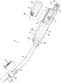
图1为根据本公开的方面的圆形缝合装置的侧面透视图,其中工具组件处于未夹持位置;1 is a side perspective view of a circular stapling device with a tool assembly in an unclamped position in accordance with aspects of the present disclosure;
图2为图1中所展示的圆形缝合装置的侧面透视图,其中砧座组件和电池组与缝合装置分离;2 is a side perspective view of the circular stapling device shown in FIG. 1 with the anvil assembly and battery pack separated from the stapling device;
图3为图2中所展示的缝合装置的电池组的分解侧面透视图;3 is an exploded side perspective view of the battery pack of the suturing device shown in FIG. 2;
图4为从图1中所展示的手柄组件的上方看的侧面透视图,所述手柄组件装配有已去除的手柄组件的主体半部分;Figure 4 is a side perspective view from above of the handle assembly shown in Figure 1 assembled with the body half of the handle assembly removed;
图5为从图4中所展示的把手组件的下方看的侧面透视图,所述手柄组件装配有已去除的手柄组件的主体半部分;Figure 5 is a side perspective view from below of the handle assembly shown in Figure 4 assembled with the body half of the handle assembly removed;
图6为图1中所展示的缝合装置的手柄组件的分解侧面透视图;6 is an exploded side perspective view of the handle assembly of the suturing device shown in FIG. 1;
图7为图1中所展示的处于未夹持位置的圆形缝合装置的侧面透视图,其中适配器组件的外部导管和手柄组件的主体以虚线显示;7 is a side perspective view of the circular suturing device shown in FIG. 1 in an unclamped position with the outer conduit of the adapter assembly and the body of the handle assembly shown in phantom;
图8为图7中所展示的所指示细节区域的放大图;FIG. 8 is an enlarged view of the indicated detail area shown in FIG. 7;
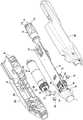
图9为图1中所展示的手柄组件的接近机构和击发机构的分解侧面透视图;Figure 9 is an exploded side perspective view of the access mechanism and firing mechanism of the handle assembly shown in Figure 1;
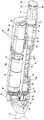
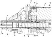
图10为沿着图1中所展示的处于未夹持位置的圆形缝合装置的纵轴截取的横截面图;10 is a cross-sectional view taken along the longitudinal axis of the circular suturing device shown in FIG. 1 in an unclamped position;
图11为图10中所展示的所指示细节区域的放大图;Figure 11 is an enlarged view of the indicated detail area shown in Figure 10;
图12为图9中所展示的所指示细节区域的放大图;Figure 12 is an enlarged view of the indicated detail area shown in Figure 9;
图13为沿着图12的截面线11-11截取的横截面图;Figure 13 is a cross-sectional view taken along section line 11-11 of Figure 12;
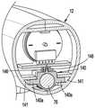
图14为沿着图5的截面线14-14截取的横截面图;Figure 14 is a cross-sectional view taken along section line 14-14 of Figure 5;
图15为沿着图5的截面线15-15截取的横截面图;Figure 15 is a cross-sectional view taken along section line 15-15 of Figure 5;
图16为沿着图5的截面线16-16截取的横截面图;Figure 16 is a cross-sectional view taken along section line 16-16 of Figure 5;
图17为沿着图5的截面线17-17截取的横截面图;Figure 17 is a cross-sectional view taken along section line 17-17 of Figure 5;
图18为沿着图5的截面线18-18截取的横截面图;Figure 18 is a cross-sectional view taken along section line 18-18 of Figure 5;
图19为沿着图1中所展示的处于夹持位置的圆形缝合装置的纵轴截取的横截面图;19 is a cross-sectional view taken along the longitudinal axis of the circular suturing device shown in FIG. 1 in the clamped position;
图20为图19中所展示的所指示细节区域的放大图;Figure 20 is an enlarged view of the indicated detail area shown in Figure 19;
图21为沿着图20的截面线21-21截取的横截面图;Figure 21 is a cross-sectional view taken along section line 21-21 of Figure 20;
图22为当正击发圆形缝合装置时穿过手柄组件的远端部分截取的侧面横截面图;和22 is a side cross-sectional view taken through the distal portion of the handle assembly when the circular stapling device is being fired; and
图23为沿着图22的截面线23-23截取的横截面图。FIG. 23 is a cross-sectional view taken along section line 23 - 23 of FIG. 22 .
具体实施方式Detailed ways
现将参看图式详细描述所公开的外科缝合装置,在图式中,相同参考标号指代若干视图中的每一个中的相同或对应元件。然而,应理解,所公开的方面仅为本公开的示例性,且可以各种形式体现。未详细描述众所周知的功能或构造以避免用不必要的细节混淆本公开。因此,本文中所公开的特定结构和功能细节不应解释为限制性的,而是只应解释为权利要求书的基础,和用于教示所属领域的技术人员用实际上任何适当的详细结构以不同方式采用本公开的代表性基础。The disclosed surgical stapling device will now be described in detail with reference to the drawings, in which like reference numerals refer to the same or corresponding elements in each of the several views. It is to be understood, however, that the disclosed aspects are merely exemplary of the present disclosure, which may be embodied in various forms. Well-known functions or constructions are not described in detail to avoid obscuring the disclosure with unnecessary detail. Therefore, specific structural and functional details disclosed herein are not to be interpreted as limiting, but merely as a basis for the claims, and for teaching one skilled in the art to employ virtually any suitable detailed structure to The representative basis of this disclosure is employed in different ways.
在本说明书中,术语“近端”通常用于指代在装置出于其预期目的进行使用期间装置的更靠近临床医生的那部分,而术语“远端”通常用于指代在装置出于其预期目的进行使用期间装置的距离临床医生较远的那部分。另外,术语“约”和“大体上”意图包括以下范围:包括所列参数和所列参数的正负百分之十。另外,术语“临床医生”通常用于指代医务人员,包括医生、护士和后勤人员。In this specification, the term "proximal end" is generally used to refer to that portion of the device that is closer to the clinician during use of the device for its intended purpose, while the term "distal end" is generally used to refer to the portion of the device that is closer to the clinician during use of the device for its intended purpose Its intended purpose is that part of the device that is farther from the clinician during use. Additionally, the terms "about" and "substantially" are intended to include ranges including the listed parameter and plus or minus ten percent of the listed parameter. Additionally, the term "clinician" is commonly used to refer to medical personnel, including doctors, nurses, and support staff.
本公开涉及一种用于执行吻合手术的外科缝合装置,其包括用于驱动击发机构的电动机和用于接近缝合装置的工具组件的手动致动的接近旋钮。The present disclosure relates to a surgical stapling device for performing an anastomotic procedure that includes a motor for driving a firing mechanism and a manually actuated access knob for accessing a tool assembly of the stapling device.
图1和图2说明通常展示为缝合装置10的圆形缝合装置,其包括手柄组件12、细长主体14或工具组件16。工具组件16包括具有环形缝钉成形表面18a(图7)的砧座组件18和具有支撑缝钉(未展示)的环形钉仓20a(图1)的壳体组件20。支撑砧座组件18以用于相对于壳体组件20在打开位置或未夹持位置(图1)与夹持位置(图19)之间移动。在本公开的各方面中,壳体组件20包括耦合到细长主体14的远端部分的近端部分22,且配接器组件20包括耦合到手柄组件12的近端部分。设想壳体组件20可以可拆卸地紧固到细长主体14和/或细长主体14可以可拆卸地紧固到手柄组件12。壳体组件还包括刀23(图1),其可在缩回位置与前进位置之间移动以在吻合手术期间切割组织。FIGS. 1 and 2 illustrate a circular suturing device, generally shown as suturing
圆形缝合装置10包括混合型手柄组件12,其包括用于使砧座组件18与壳体组件20接近的手动操作的接近旋钮74,和用于启动电动机26(图4)以进行缝合和切割组织的击发按钮24。手柄组件12包括主体部分28,其形状符合人体工程学以由临床医生夹持。主体部分28限定内部空腔30(图4)和外部凹槽32(图2)。内部空腔30收纳下文所描述的手柄组件的驱动组件。外部凹槽32收纳电池组34,其可拆卸地耦合到手柄组件12的主体部分28。电池组34包括外壳36和收纳在外壳36内的一或多个电池38。电池组34的外壳36具有形成有弹性闩锁40的远端部分,所述弹性闩锁40收纳在形成在主体部分28中的狭槽42(图2)中。弹性闩锁40以扣合方式接合主体部分28,以将电池组34可拆卸地紧固到手柄组件12的主体部分28。The
图3说明手柄组件12的电池组34。在本公开的各方面中,电池组34的外壳36由半部分36a、36b形成,所述半部分连接在一起以限定收纳电池38的空腔46。电池38支撑在包括电触点50的印刷电路板48上。半部分36a、36b耦合在一起时限定收纳电触点50的开口52,使得电触点50可接合手柄组件12内的触点以向电动机26供应电源。电池触点可呈弹簧夹54的形式。FIG. 3 illustrates the
图4到图6说明手柄组件12的主体部分28的内部空腔30和收纳在空腔30中的组件。手柄组件12包括印刷电路板58,其将内部空腔30分成上半部30a和下半部30b,如图4中所见。印刷电路板58紧固在手柄组件12的主体部分28的半部分28a、28b(图6)之间,且将电动机26支撑在电池组34的远端的空腔30的上半部30a内。电动机26包括旋转驱动轴59(图6),其支撑与印刷电路板58中所限定的断流器62对准的输出齿轮60(图15)。驱动轴59的旋转引起输出齿轮60的对应旋转。FIGS. 4-6 illustrate the
印刷电路板58包括远端部分和近端部分。印刷电路板58的近端部分支撑电池触点54,而58的远端部分支撑安全开关64。安全开关64定位成由定位在手柄组件12的主体部分28的相对侧的安全按钮66启动,如下文进一步详细描述。58的远端部分还支撑定位成由击发按钮24启动的击发开关68。虽然未展示,但58还可以支撑将电池组34和电动机26电耦合到开关64和68的电路,且包括微控制器和电动机驱动器电路系统。腔体30的下半部30b收纳接近机构72的近端部分和击发机构73的近端部分。The printed
图5到图11说明接近机构72,其包括接近旋钮74、砧座夹持螺杆76、可旋转套筒78、第一和第二螺杆弹性延伸部80、82(图10)和砧座保持器套管针84(图7)。可旋转套筒78包括圆柱形中空主体部分86和支撑在中空主体部分86的远端部分上的圆柱形轴环88。可旋转套筒78限定纵向通孔90。(图9)轴环88的直径大于主体部分86,且收纳在向内延伸的凸缘92(图5)之间,凸缘92形成在手柄组件12的主体部分28的半部分28a、28b的内壁上。凸缘92之间的轴环88的收纳将可旋转套筒78轴向地固定在手柄组件12的主体部分28内,同时准许可旋转套筒78旋转。可旋转套筒78的近端部分延伸穿过手柄组件12的主体部分28的近端中的开口94(图6)且固定地耦合到接近旋钮72。可旋转套筒78的中空主体部分86包括一对直径相对的肋96(图9),其形成在主体部分76的外表面上且收纳旋钮74内所限定的槽(未展示)内以将可旋转套筒78可旋转地固定到接近旋钮74,使得接近旋钮72的旋转引起可旋转套筒78同时旋转。在本公开的各方面中,接近旋钮74的远端部分限定环形通道74a,其收纳形成在手柄组件12的主体部分28的内壁上的内部肋75(图11),以将接近旋钮74可旋转地固定到手柄组件12的主体部分28。FIGS. 5-11 illustrate the
砧座夹持螺杆76的近端半部包括螺旋形沟道98,且定位在可旋转套筒78的通孔90内。接脚100(图11)支撑在可旋转套筒78(图11)的轴环88上且从轴环88径向延伸到螺旋形沟道98中。由于可旋转套筒78相对于手柄组件12的主体部分28轴向地固定,所以可旋转套筒78围绕砧座夹持螺杆76的旋转使得接脚100(图11)沿着砧座夹持螺杆76的螺旋形沟道98移动,从而产生砧座夹持螺杆76在手柄组件12的主体部分28内的轴向移动。The proximal half of the
砧座夹持螺杆76具有限定横向狭槽102(图9)的远端部分。螺杆延伸部80、82各自包括位于近端的柔性平带部分104(图10)和位于远端的平带部分106。带部分104通过接脚108(图9)紧固在驱动螺杆76的横向槽102内以将带部分80、82紧固到驱动螺杆76。带部分80、82从驱动螺杆76穿过细长主体14(图10)延伸到壳体组件20中。螺杆延伸部80、82的平带部分106通过引脚112(图10)紧固在砧座保持器84中所限定的槽110(图10)内以将砧座保持器84紧固到螺杆延伸部80、82。当旋转接近旋钮74以在手柄组件12的主体部分28内轴向地移动砧座夹持螺杆76时,螺杆延伸部80、82也在细长主体14内轴向地移动,且砧座保持器84在壳体组件20内轴向地移动(图10)。设想,虽然引脚展示为将螺杆延伸部80、82牢固到驱动螺杆76和砧座保持器84(图10),但可使用其它技术和/或附接装置来执行这种功能。The
砧座保持器84配置成可拆卸地耦合到砧座组件18(图10),使得接近旋钮74的旋转使砧座组件18相对于壳体组件20在打开位置与夹持位置之间移动。美国专利第7,303,106号描述了一种缝合装置,其包括可拆卸地耦合在一起且适合与缝合装置10一起使用的砧座组件和砧座保持器。Anvil holder 84 is configured to be removably coupled to anvil assembly 18 ( FIG. 10 ) such that rotation of
接近旋钮74限定通孔114且支撑指示器帽116。指示器帽116固定地紧固到接近旋钮74的近端部分且限定围绕指示器帽116间隔开的窗口118。接近旋钮74支撑指示器组件120(图9),其包括指示器122、调整部件或螺钉124和偏置部件126。指示器122包括圆柱形主体128和直径大于圆柱形主体128的头部部分130。指示器122的头部部分130收纳在指示器帽116内且包括标记132(图9)。响应于驱动螺杆76朝向缩回位置的移动,指示器122可在接近旋钮74内从前进位置朝向缩回位置移动,以将指示器122的在指示器帽116内的头部部分130从前进位置移动到缩回位置。当缝合装置10移动到夹持位置时,标记132通过指示器帽116中的窗口118可见。如本文中所使用,术语“夹持位置”是指砧座组件18与壳体组件20的钉仓20a(图1)足够接近地定位,使得缝钉可抵靠砧座组件18适当地形成的位置。因此,夹持位置包括一系列位置。夹持位置是由被夹持组织的厚度和临床医生的判断决定。The
将调整螺钉124拧入指示器122的远端部分中所限定的螺纹孔136中以将调整螺钉124紧固到指示器122。调整螺钉124延伸到可旋转套筒78的通孔90中且包括远端,当驱动螺杆76朝向缩回位置移动时,所述远端定位成接合驱动螺杆76。偏置部件126定位在指示器帽116与指示器122之间以朝向前进位置推动指示器122。当驱动螺杆76朝向其缩回位置(图20)移动时,驱动螺杆76接合调整螺钉124以在接近旋钮74内向近端移动调整螺钉124和指示器122。当指示器122在接近旋钮74内移动时,指示器122的头部部分130在指示器帽116内移动,使得标记132通过指示器帽116中的窗口118变得可见。这向临床医生提供了缝合装置10(图1)处于预备击发位置的指示,即砧座组件18和壳体组件20处于足够接近的相对位置以促进缝钉的恰当形成。可通过在缝合装置10(图1)的制造期间旋转调整螺钉124来调整或校准调整螺钉124在可旋转套筒78的通孔90内的位置,以将调整螺钉124适当地定位可旋转套筒78的通孔90内,使得当砧座组件18和壳体组件20彼此适当地间隔开时,标记132移动到指示器帽116的窗口118中。The
驱动螺杆76支撑托架140(图9),其通过托架螺钉142紧固到驱动螺杆76。托架140收纳在驱动螺杆76中的螺纹孔144中,且可在驱动螺杆76在手柄组件12的主体部分28内在缩回位置与前进位置之间移动时随驱动螺杆76移动。托架140包括细长肋146(图9),当缝合装置10(图1)移动到夹持位置以启动如下文所描述的安全性开关时,所述细长肋146接合或启动支撑在手柄组件12内的开关,例如光断路器148(图17)。托架140还包括翼140a(图16),其收纳在手柄组件12的主体部分28内所限定的槽141中,以防止托架140旋转且在缝合装置10的手柄组件12的主体部分28内引导托架140。Drive
图5到图13说明击发机构73(图8),其包括击发齿轮150、击发螺钉152、延伸器154、推进器连杆156(图10)和推进器158(图10)。击发齿轮150围绕驱动螺杆76可旋转地支撑,且限定内螺纹孔160和包括多个齿轮齿162a的外齿轮部件162。齿轮部件162收纳在形成在手柄组件12的主体部分28上的凸缘164(图13)之间,使得击发齿轮150可以在手柄组件12的主体部分28内旋转但被轴向地固定。击发螺钉152收纳在击发齿轮150的内螺纹孔160内且包括外螺纹部分166和内通孔168。驱动螺杆76延伸穿过击发螺钉152的通孔168,使得击发螺钉152可围绕驱动螺杆76滑动。FIGS. 5-13 illustrate the firing mechanism 73 ( FIG. 8 ), which includes the
击发螺钉152包括远端部分152a,其具有减小的直径且收纳在延伸器154的近端部分内。击发螺钉152的远端部分152a包括直径相对的纵向狭槽170,其与形成在延伸器154内的纵向狭槽172对准。接脚173(图14)支撑在主体部分28上,且延伸穿过槽170和172并进入形成在手柄组件12的主体部分28中的沟道175(图9)中,以防止延伸器154相对于击发螺钉152旋转。延伸器154的远端部分收纳推进器连杆156的近端部分,且推进器连杆156的远端部分与收纳在壳体组件20(图10)内的推进器158接合。在本公开的各方面中,推力轴承159(图23)支撑在手柄组件12的主体部分28内且与击发齿轮150的近端接合,以吸收由击发齿轮150产生的击发力。The firing
当启动电动机26时,电动机26的输出齿轮60旋转。输出齿轮60与击发齿轮150的外齿轮部件162(图15)接合,使得输出齿轮60的旋转使击发齿轮150旋转。击发齿轮150的内螺纹孔160与击发螺钉152的外螺纹部分166以螺纹方式接合。当击发齿轮150旋转时,击发螺钉152在击发齿轮150内围绕驱动螺杆76纵向驱动。击发螺钉152的远端部分152a与延伸器154的近端部分接合,且延伸器154的远端部分与推进器连杆156的近端部分接合,使得击发螺钉152的前进使缝合装置10(图10)的细长主体14内的推进器连杆156前进。推进器连杆156的远端部分耦合到推进器158,使得推进器连杆156的前进使得推进器158(图10)在壳体组件20内移动以从壳体组件20弹出缝钉。When the
图6说明安全按钮64、安全开关66、击发按钮24和击发开关68。当接近旋钮74手动地致动以将缝合装置10(图1)移动到预备击发区域中的夹持位置时,托架140上的细长肋146将移动到光断路器148(图5)中以中断光束。当这种情况发生时,通过手柄组件12内的电路系统连接到安全开关66的光断路器148将使安全按钮64发光以向临床医生提供能够击发缝合装置10的指示。安全按钮64可包括LED或其它照明装置以照亮安全按钮64。为了击发缝合装置10,必须按压安全按钮64中的一个以关闭安全开关66且启动击发开关68。一旦按压安全按钮64中的一个,便可按压击发按钮24以关闭击发开关68且启动缝合装置10的击发,即启动电动机26以使推进器连杆156前进且使推进器158前进以从壳体组件20击发缝钉。击发按钮24也可以例如用发光二极管(LED)照亮。举例来说,当按压安全按钮64时,击发按钮24将发光以向临床医生提供缝合装置10准备好击发的指示。需要注意的是,安全开关66将不启动击发开关68,直到托架140上的细长肋146移动到光断路器148中。FIG. 6 illustrates
在本公开的各方面中,安全按钮64和击发按钮24可配置成在缝合装置10移动到夹持位置之前,当缝合装置10耦合到电池组34时闪烁。在本公开的这一方面中,安全按钮64将闪烁直到缝合装置移动到夹持位置。当缝合装置10移动到夹持位置时,安全按钮64将持续发光,但击发按钮24将继续间歇性地闪烁直到按下安全按钮64中的一个为止。当按下安全按钮64中的一个以关闭安全开关66时,击发按钮24将持续发光以向临床医生指示缝合装置10准备好击发。在本公开的各方面中,缝合装置10内的电路系统包括计时器,如果在按下安全按钮64中的一个之后在预定时间内没有击发缝合装置10,那么计时器重置安全开关66。如果在预定时间内没有击发缝合装置10,那么将重置安全开关66,使得必须再次按下安全按钮64中的一个以启动击发按钮24。在本公开的各方面中,预定时间可以是从大约10秒到约30秒,但可设想其它时间。In aspects of the present disclosure, the
图19到图21说明在缝合装置10从打开位置移动到夹持位置时的缝合装置10。当接近旋钮74在图20中箭头“A”所指示的方向上旋转时,驱动螺杆76在箭头“B”的方向上缩回。如上所述,驱动螺杆76耦合到螺杆延伸部80、82,且螺杆延伸部80、82耦合到砧座保持器84,使得驱动轴76在箭头“B”的方向上的移动使砧座保持器在图19中的箭头“C”的方向上移动,进而使砧座组件18在箭头“D”的方向上移动到夹持和预备击发位置(图19)。如图21中所示,当驱动螺杆76缩回且缝合装置10移动到夹持位置时,托架140上的细长肋146移动到光断路器148中以启动安全开关66。当这种情况发生时,安全开关66将发光以向临床医生提供缝合装置10准备好击发的指示。在这个位置,可按下安全按钮64中的一个以启动击发按钮24。当按下安全按钮64中的一个时,击发按钮24将发光。19-21 illustrate the
图22和图23说明在击发缝合装置10时的缝合装置10。当按下击发按钮24以启动击发开关68时,启动电动机以使输出齿轮60旋转。当输出齿轮60旋转时,输出齿轮60使击发齿轮150旋转。击发齿轮150的内螺纹孔160与击发螺钉152的外螺纹部分166以螺纹方式接合。当击发齿轮150旋转时,击发螺钉152在击发齿轮150内围绕驱动螺杆76纵向驱动。击发螺钉152的远端部分152与延伸器154的近端部分接合,且延伸器154的远端部分与推进器连杆156的近端部分接合,使得击发螺钉152的前进使缝合装置10(图10)的细长主体14内的推进器连杆156前进。推进器连杆156的远端部分耦合到推进器158,使得推进器连杆156的前进使得推进器158(图10)在壳体组件20内移动以从壳体组件20弹出缝钉。所公开缝合装置10将手动操作的缝合装置和电动缝合装置的优点结合到可制造为一次性器械的单个器械中。更确切地说,缝合装置10包括手动操作的接近机构72,其为临床医生保留触觉反馈以用于用户控制的压缩。另外,缝合装置10包括电动或机动的击发机构73,其允许对组织移动的影响最小的受控稳定击发。22 and 23 illustrate the
所属领域的技术人员将理解,在本文中具体描述且在附图中示出的装置和方法是非限制性的示例性实施例。设想,在不脱离本公开的范围的情况下,结合一个示例性实施例说明或描述的元件和特征可与另一个示例性实施例的元件和特征组合。同样,所属领域的技术人员也将基于上述实施例理解本公开的其它特征和优点。因此,除了由所附权利要求指示之外,本公开不受已经特别展示和描述的内容的限制。Those skilled in the art will understand that the apparatus and methods specifically described herein and illustrated in the accompanying drawings are non-limiting exemplary embodiments. It is contemplated that elements and features illustrated or described in connection with one exemplary embodiment may be combined with elements and features of another exemplary embodiment without departing from the scope of the present disclosure. Likewise, those skilled in the art will also appreciate other features and advantages of the present disclosure based on the above-described embodiments. Accordingly, the present disclosure is not to be limited by what has been particularly shown and described, except as indicated by the appended claims.
Claims (20)
Translated fromChineseApplications Claiming Priority (4)
| Application Number | Priority Date | Filing Date | Title |
|---|---|---|---|
| US202163140066P | 2021-01-21 | 2021-01-21 | |
| US63/140,066 | 2021-01-21 | ||
| US17/543,107 | 2021-12-06 | ||
| US17/543,107US11877750B2 (en) | 2021-01-21 | 2021-12-06 | Surgical stapler with powered and manual functions |
Publications (1)
| Publication Number | Publication Date |
|---|---|
| CN114795354Atrue CN114795354A (en) | 2022-07-29 |
Family
ID=79831350
Family Applications (1)
| Application Number | Title | Priority Date | Filing Date |
|---|---|---|---|
| CN202210038033.XAPendingCN114795354A (en) | 2021-01-21 | 2022-01-13 | Surgical stapler with electric and manual functions |
Country Status (4)
| Country | Link |
|---|---|
| US (1) | US11877750B2 (en) |
| EP (1) | EP4032487B1 (en) |
| CN (1) | CN114795354A (en) |
| CA (1) | CA3142378A1 (en) |
Families Citing this family (2)
| Publication number | Priority date | Publication date | Assignee | Title |
|---|---|---|---|---|
| EP3573543A4 (en)* | 2017-01-25 | 2021-03-03 | Covidien LP | Circular stapling device and method of use |
| US11877750B2 (en)* | 2021-01-21 | 2024-01-23 | Covidien Lp | Surgical stapler with powered and manual functions |
Family Cites Families (445)
| Publication number | Priority date | Publication date | Assignee | Title |
|---|---|---|---|---|
| CA908529A (en) | 1972-08-29 | V. Astafiev Georgy | Surgical instrument for suturing hollow organs in infants | |
| DE1057729B (en) | 1954-03-29 | 1959-05-21 | Lameris Instr N V | Surgical device for connecting two parts of the intestine |
| GB787043A (en) | 1954-09-15 | 1957-11-27 | Sylvania Electric Prod | Method for production of silicon |
| US3011554A (en) | 1956-01-23 | 1961-12-05 | Schlumberger Well Surv Corp | Apparatus for investigating earth formations |
| FR1461464A (en) | 1965-08-20 | 1966-02-25 | Niiex Khirurgicheskoi Apparatu | Surgical device for suturing organs |
| CH470170A (en) | 1968-02-02 | 1969-03-31 | Vnii Khirurgicheskoi Apparatur | Device for applying round anastomoses |
| US3638652A (en) | 1970-06-01 | 1972-02-01 | James L Kelley | Surgical instrument for intraluminal anastomosis |
| US3771526A (en) | 1972-02-07 | 1973-11-13 | P Rudie | Anastomosis clamp |
| US4573468A (en) | 1977-05-26 | 1986-03-04 | United States Surgical Corporation | Hollow body organ stapling instrument and disposable cartridge employing relief vents |
| US4603693A (en) | 1977-05-26 | 1986-08-05 | United States Surgical Corporation | Instrument for circular surgical stapling of hollow body organs and disposable cartridge therefor |
| US4304236A (en) | 1977-05-26 | 1981-12-08 | United States Surgical Corporation | Stapling instrument having an anvil-carrying part of particular geometric shape |
| NL7711347A (en) | 1977-10-17 | 1979-04-19 | Carl Robert Erik Daantje | Stapling instrument for joining intestine ends - has head coupling rod in two parts screwing together with hand grip |
| US4207898A (en) | 1978-03-27 | 1980-06-17 | Senco Products, Inc. | Intralumenal anastomosis surgical stapling instrument |
| US4198982A (en) | 1978-03-31 | 1980-04-22 | Memorial Hospital For Cancer And Allied Diseases | Surgical stapling instrument and method |
| DE2947107A1 (en) | 1978-12-07 | 1980-06-26 | United States Surgical Corp | ACCURATELY ALIGNED CARTRIDGE AND INSTRUMENT FOR CLAMPING ANASTOMOSES |
| SU1088712A1 (en) | 1979-11-14 | 1984-04-30 | Всесоюзный научно-исследовательский и испытательный институт медицинской техники | Apparatus for circular suture of blood vessels |
| AU534210B2 (en) | 1980-02-05 | 1984-01-12 | United States Surgical Corporation | Surgical staples |
| US4319576A (en)* | 1980-02-26 | 1982-03-16 | Senco Products, Inc. | Intralumenal anastomosis surgical stapling instrument |
| US4289133A (en) | 1980-02-28 | 1981-09-15 | Senco Products, Inc. | Cut-through backup washer for the scalpel of an intraluminal surgical stapling instrument |
| US4606343A (en) | 1980-08-18 | 1986-08-19 | United States Surgical Corporation | Self-powered surgical fastening instrument |
| US4351466A (en) | 1980-10-16 | 1982-09-28 | United States Surgical Corporation | Disposable instrument for surgical fastening |
| US4379457A (en) | 1981-02-17 | 1983-04-12 | United States Surgical Corporation | Indicator for surgical stapler |
| US4476863A (en) | 1981-03-09 | 1984-10-16 | Kanshin Nikolai N | Surgical instrument for establishing circular coloanastomoses |
| US4632290A (en) | 1981-08-17 | 1986-12-30 | United States Surgical Corporation | Surgical stapler apparatus |
| US4576167A (en) | 1981-09-03 | 1986-03-18 | United States Surgical Corporation | Surgical stapler apparatus with curved shaft |
| SU1114405A1 (en) | 1982-02-23 | 1984-09-23 | Всесоюзный научно-исследовательский и испытательный институт медицинской техники | Surgical suturing apparatus for placing compression anastomoses on the organs of digestive tract |
| US4473077A (en) | 1982-05-28 | 1984-09-25 | United States Surgical Corporation | Surgical stapler apparatus with flexible shaft |
| US4485817A (en) | 1982-05-28 | 1984-12-04 | United States Surgical Corporation | Surgical stapler apparatus with flexible shaft |
| US4488523A (en) | 1982-09-24 | 1984-12-18 | United States Surgical Corporation | Flexible, hydraulically actuated device for applying surgical fasteners |
| DE3301713A1 (en) | 1983-01-20 | 1984-07-26 | Horst Dr. 3004 Isernhagen Ziegler | Surgical clip suture apparatus for producing circular joins |
| US4592354A (en) | 1983-10-11 | 1986-06-03 | Senmed, Inc. | Tissue retention spool for intraluminal anastomotic surgical stapling instrument and methods |
| US4505414A (en) | 1983-10-12 | 1985-03-19 | Filipi Charles J | Expandable anvil surgical stapler |
| US4550870A (en) | 1983-10-13 | 1985-11-05 | Alchemia Ltd. Partnership | Stapling device |
| IT1173284B (en) | 1984-02-16 | 1987-06-18 | Riccardo Rosati | CIRCULAR MECHANICAL STAPLING MACHINE |
| US4667673A (en) | 1984-03-12 | 1987-05-26 | American Cyanamid Company | Anastomotic device applicator and method |
| US4671445A (en) | 1984-08-09 | 1987-06-09 | Baxter Travenol Laboratories, Inc. | Flexible surgical stapler assembly |
| US4754909A (en) | 1984-08-09 | 1988-07-05 | Barker John M | Flexible stapler |
| US4665917A (en) | 1985-01-28 | 1987-05-19 | Ethicon, Inc. | Tissue gripper for use with intraluminal stapling device |
| US4703887A (en) | 1985-01-28 | 1987-11-03 | Ethicon, Inc. | Collapsible purse string aid for use with intraluminal stapling device |
| AU582625B2 (en) | 1985-01-28 | 1989-04-06 | Ethicon Inc. | Tissue gripper for use with intraluminal stapling device |
| JPS635697Y2 (en) | 1985-04-04 | 1988-02-17 | ||
| JPS62140776A (en) | 1985-12-16 | 1987-06-24 | 海老原 代師行 | Stapler |
| US4903697A (en) | 1986-03-27 | 1990-02-27 | Semion Resnick | Cartridge assembly for a surgical stapling instrument |
| US4700703A (en) | 1986-03-27 | 1987-10-20 | Semion Resnick | Cartridge assembly for a surgical stapling instrument |
| US4817847A (en) | 1986-04-21 | 1989-04-04 | Finanzaktiengesellschaft Globe Control | Instrument and a procedure for performing an anastomosis |
| US4752024A (en) | 1986-10-17 | 1988-06-21 | Green David T | Surgical fastener and surgical stapling apparatus |
| US4917114A (en) | 1986-10-17 | 1990-04-17 | United States Surgical Corporation | Surgical fastener and surgical stapling apparatus |
| US4776506A (en) | 1986-11-13 | 1988-10-11 | United States Surgical Corporation | Surgical stapler apparatus |
| US4873977A (en) | 1987-02-11 | 1989-10-17 | Odis L. Avant | Stapling method and apparatus for vesicle-urethral re-anastomosis following retropubic prostatectomy and other tubular anastomosis |
| US5119983A (en) | 1987-05-26 | 1992-06-09 | United States Surgical Corporation | Surgical stapler apparatus |
| US5158222A (en) | 1987-05-26 | 1992-10-27 | United States Surgical Corp. | Surgical stapler apparatus |
| US5285944A (en) | 1987-05-26 | 1994-02-15 | United States Surgical Corporation | Surgical stapler apparatus |
| SU1616624A1 (en) | 1987-07-14 | 1990-12-30 | Предприятие П/Я А-3697 | Surgical suturing apparatus |
| SU1509052A1 (en) | 1988-01-18 | 1989-09-23 | С. А. Попов | Surgical suturing apparatus |
| US4907591A (en) | 1988-03-29 | 1990-03-13 | Pfizer Hospital Products Group, Inc. | Surgical instrument for establishing compression anastomosis |
| US5193731A (en) | 1988-07-01 | 1993-03-16 | United States Surgical Corporation | Anastomosis surgical stapling instrument |
| US5005749A (en) | 1988-07-01 | 1991-04-09 | United States Surgical Corp. | Anastomosis surgical stapling instrument |
| ES2011110A6 (en) | 1988-09-02 | 1989-12-16 | Lopez Hervas Pedro | Hydraulic device with flexible body for surgical anastomosts |
| AU4742190A (en) | 1988-11-29 | 1990-06-26 | Bruce S. Gingold | Surgical stapling apparatus |
| US5197648A (en) | 1988-11-29 | 1993-03-30 | Gingold Bruce S | Surgical stapling apparatus |
| US4893662A (en) | 1988-12-06 | 1990-01-16 | Vito Gervasi | Cutting tool |
| CH677728A5 (en) | 1989-10-17 | 1991-06-28 | Bieffe Medital Sa | |
| US5366462A (en) | 1990-08-28 | 1994-11-22 | Robert L. Kaster | Method of side-to-end vascular anastomotic stapling |
| US5047039A (en) | 1990-09-14 | 1991-09-10 | Odis Lynn Avant | Method and apparatus for effecting dorsal vein ligation and tubular anastomosis and laparoscopic prostatectomy |
| US5253793A (en) | 1990-09-17 | 1993-10-19 | United States Surgical Corporation | Apparatus for applying two-part surgical fasteners |
| US5104025A (en) | 1990-09-28 | 1992-04-14 | Ethicon, Inc. | Intraluminal anastomotic surgical stapler with detached anvil |
| US5042707A (en) | 1990-10-16 | 1991-08-27 | Taheri Syde A | Intravascular stapler, and method of operating same |
| CA2055943C (en) | 1990-12-06 | 2003-09-23 | Daniel P. Rodak | Surgical fastening apparatus with locking mechanism |
| US5122156A (en) | 1990-12-14 | 1992-06-16 | United States Surgical Corporation | Apparatus for securement and attachment of body organs |
| US5222963A (en) | 1991-01-17 | 1993-06-29 | Ethicon, Inc. | Pull-through circular anastomosic intraluminal stapler with absorbable fastener means |
| ATE135182T1 (en) | 1991-03-29 | 1996-03-15 | Perouse Implant Lab | SURGICAL STAPLE SEWING DEVICE |
| US5221036A (en) | 1991-06-11 | 1993-06-22 | Haruo Takase | Surgical stapler |
| US5350104A (en) | 1991-08-23 | 1994-09-27 | Ethicon, Inc. | Sealing means for endoscopic surgical anastomosis stapling instrument |
| US5333773A (en) | 1991-08-23 | 1994-08-02 | Ethicon, Inc. | Sealing means for endoscopic surgical anastomosis stapling instrument |
| GR920100358A (en) | 1991-08-23 | 1993-06-07 | Ethicon Inc | Surgical anastomosis stapling instrument. |
| US5474223A (en) | 1991-10-18 | 1995-12-12 | United States Surgical Corporation | Surgical fastener applying apparatus |
| US5443198A (en) | 1991-10-18 | 1995-08-22 | United States Surgical Corporation | Surgical fastener applying apparatus |
| US5197649A (en) | 1991-10-29 | 1993-03-30 | The Trustees Of Columbia University In The City Of New York | Gastrointestinal endoscoptic stapler |
| US5433721A (en) | 1992-01-17 | 1995-07-18 | Ethicon, Inc. | Endoscopic instrument having a torsionally stiff drive shaft for applying fasteners to tissue |
| US5188638A (en) | 1992-02-06 | 1993-02-23 | Tzakis Andreas G | Apparatus and method for preforming anastomosis fastener securement of hollow organs |
| US5271543A (en) | 1992-02-07 | 1993-12-21 | Ethicon, Inc. | Surgical anastomosis stapling instrument with flexible support shaft and anvil adjusting mechanism |
| US5348259A (en) | 1992-02-10 | 1994-09-20 | Massachusetts Institute Of Technology | Flexible, articulable column |
| US5282810A (en) | 1992-04-08 | 1994-02-01 | American Cyanamid Company | Surgical anastomosis device |
| US5425738A (en) | 1992-04-08 | 1995-06-20 | American Cyanamid Company | Endoscopic anastomosis ring insertion device and method of use thereof |
| US5355897A (en) | 1992-04-16 | 1994-10-18 | Ethicon, Inc. | Method of performing a pyloroplasty/pylorectomy using a stapler having a shield |
| US5344059A (en) | 1992-05-19 | 1994-09-06 | United States Surgical Corporation | Surgical apparatus and anvil delivery system therefor |
| US5314435A (en) | 1992-05-19 | 1994-05-24 | United States Surgical Corporation | Anvil delivery system |
| JPH0647050A (en) | 1992-06-04 | 1994-02-22 | Olympus Optical Co Ltd | Tissue suture and ligature device |
| US5658300A (en) | 1992-06-04 | 1997-08-19 | Olympus Optical Co., Ltd. | Tissue fixing surgical instrument, tissue-fixing device, and method of fixing tissues |
| US5360154A (en) | 1992-07-17 | 1994-11-01 | United States Surgical Corporation | Apparatus for creating partial anastomoses |
| US5330486A (en) | 1992-07-29 | 1994-07-19 | Wilk Peter J | Laparoscopic or endoscopic anastomosis technique and associated instruments |
| US5261920A (en) | 1992-08-21 | 1993-11-16 | Ethicon, Inc. | Anvil bushing for circular stapler |
| US5368215A (en) | 1992-09-08 | 1994-11-29 | United States Surgical Corporation | Surgical apparatus and detachable anvil rod therefor |
| US5309927A (en) | 1992-10-22 | 1994-05-10 | Ethicon, Inc. | Circular stapler tissue retention spring method |
| US5314436A (en) | 1992-10-30 | 1994-05-24 | Wilk Peter J | Method and apparatus for performing end-to-end anastomoses |
| US5404870A (en) | 1993-05-28 | 1995-04-11 | Ethicon, Inc. | Method of using a transanal inserter |
| US5503320A (en) | 1993-08-19 | 1996-04-02 | United States Surgical Corporation | Surgical apparatus with indicator |
| US5447514A (en) | 1993-10-01 | 1995-09-05 | United States Surgical Corporation | Circular anastomosis device |
| US5454825A (en) | 1993-10-01 | 1995-10-03 | United States Surgical Corporation | Circular anastomosis device with seal |
| US5522534A (en) | 1993-10-01 | 1996-06-04 | United States Surgical Corporation | Anvil for surgical stapler |
| US5437684A (en) | 1993-10-01 | 1995-08-01 | United States Surgical Corporation | Circular anastomosis device |
| CA2132917C (en) | 1993-10-07 | 2004-12-14 | John Charles Robertson | Circular anastomosis device |
| US5503635A (en) | 1993-11-12 | 1996-04-02 | United States Surgical Corporation | Apparatus and method for performing compressional anastomoses |
| DE4407668A1 (en) | 1994-03-09 | 1995-09-14 | Ferdinand Dr Koeckerling | Surgical anastomotic ring setting device |
| US5464415A (en) | 1994-03-15 | 1995-11-07 | Chen; Te-Chuan | Sutureless intestinal anastomosis gun |
| US5860581A (en) | 1994-03-24 | 1999-01-19 | United States Surgical Corporation | Anvil for circular stapler |
| US5715987A (en) | 1994-04-05 | 1998-02-10 | Tracor Incorporated | Constant width, adjustable grip, staple apparatus and method |
| CA2147800C (en) | 1994-05-26 | 2006-07-11 | John Charles Robertson | Circular anastomosis device |
| US5881943A (en) | 1994-06-17 | 1999-03-16 | Heartport, Inc. | Surgical anastomosis apparatus and method thereof |
| US5732872A (en) | 1994-06-17 | 1998-03-31 | Heartport, Inc. | Surgical stapling instrument |
| WO1995035065A1 (en) | 1994-06-17 | 1995-12-28 | Heartport, Inc. | Surgical stapling instrument and method thereof |
| CA2146508C (en) | 1994-08-25 | 2006-11-14 | Robert H. Schnut | Anvil for circular stapler |
| US5685474A (en)* | 1994-10-04 | 1997-11-11 | United States Surgical Corporation | Tactile indicator for surgical instrument |
| US7235089B1 (en) | 1994-12-07 | 2007-06-26 | Boston Scientific Corporation | Surgical apparatus and method |
| US5868760A (en) | 1994-12-07 | 1999-02-09 | Mcguckin, Jr.; James F. | Method and apparatus for endolumenally resectioning tissue |
| US5720755A (en) | 1995-01-18 | 1998-02-24 | Dakov; Pepi | Tubular suturing device and methods of use |
| US5904697A (en) | 1995-02-24 | 1999-05-18 | Heartport, Inc. | Devices and methods for performing a vascular anastomosis |
| DE19509115C2 (en) | 1995-03-16 | 1997-11-27 | Deutsche Forsch Luft Raumfahrt | Surgical device for preparing an anastomosis using minimally invasive surgical techniques |
| US5769841A (en) | 1995-06-13 | 1998-06-23 | Electroscope, Inc. | Electrosurgical apparatus for laparoscopic and like procedures |
| US5641111A (en) | 1995-06-28 | 1997-06-24 | Ethicon Endo-Surgery, Inc. | Surgical stapling instrument with anvil cutting guide |
| US5749896A (en) | 1995-07-18 | 1998-05-12 | Cook; Melvin S. | Staple overlap |
| US5839639A (en) | 1995-08-17 | 1998-11-24 | Lasersurge, Inc. | Collapsible anvil assembly and applicator instrument |
| US5814055A (en) | 1995-09-19 | 1998-09-29 | Ethicon Endo-Surgery, Inc. | Surgical clamping mechanism |
| AU701033B2 (en) | 1995-10-31 | 1999-01-21 | Bernafon Ag | Method and anastomotic instrument for use when performing an end-to-side anastomosis |
| US5836503A (en) | 1996-04-22 | 1998-11-17 | United States Surgical Corporation | Insertion device for surgical apparatus |
| US6050472A (en) | 1996-04-26 | 2000-04-18 | Olympus Optical Co., Ltd. | Surgical anastomosis stapler |
| US6119913A (en) | 1996-06-14 | 2000-09-19 | Boston Scientific Corporation | Endoscopic stapler |
| US6440146B2 (en) | 1996-07-23 | 2002-08-27 | United States Surgical Corporation | Anastomosis instrument and method |
| US6024748A (en) | 1996-07-23 | 2000-02-15 | United States Surgical Corporation | Singleshot anastomosis instrument with detachable loading unit and method |
| US20020019642A1 (en) | 1996-07-23 | 2002-02-14 | Keith Milliman | Anastomosis instrument and method for performing same |
| US5833698A (en) | 1996-07-23 | 1998-11-10 | United States Surgical Corporation | Anastomosis instrument and method |
| US5855312A (en) | 1996-07-25 | 1999-01-05 | Toledano; Haviv | Flexible annular stapler for closed surgery of hollow organs |
| US5853395A (en) | 1997-02-18 | 1998-12-29 | Dexterity, Inc. | Extracorporeal pneumoperitoneum enclosure and method of use |
| US6338737B1 (en) | 1997-07-17 | 2002-01-15 | Haviv Toledano | Flexible annular stapler for closed surgery of hollow organs |
| US5865361A (en) | 1997-09-23 | 1999-02-02 | United States Surgical Corporation | Surgical stapling apparatus |
| US6117148A (en) | 1997-10-17 | 2000-09-12 | Ravo; Biagio | Intraluminal anastomotic device |
| US5951576A (en) | 1998-03-02 | 1999-09-14 | Wakabayashi; Akio | End-to-side vascular anastomosing stapling device |
| US6279809B1 (en) | 1998-03-10 | 2001-08-28 | Enrico Nicolo | Circular stapler for side to end, side to side and end to side anastomosis |
| AU751697B2 (en) | 1998-05-11 | 2002-08-22 | Surgical Connections, Inc. | Devices and methods for treating e.g. urinary stress incontinence |
| US6517566B1 (en) | 1998-05-11 | 2003-02-11 | Surgical Connections, Inc. | Devices and methods for treating e.g. urinary stress incontinence |
| US6478210B2 (en) | 2000-10-25 | 2002-11-12 | Scimed Life Systems, Inc. | Method and device for full thickness resectioning of an organ |
| US6601749B2 (en) | 1998-06-19 | 2003-08-05 | Scimed Life Systems, Inc. | Multi fire full thickness resectioning device |
| US6126058A (en) | 1998-06-19 | 2000-10-03 | Scimed Life Systems, Inc. | Method and device for full thickness resectioning of an organ |
| US6585144B2 (en) | 1998-06-19 | 2003-07-01 | Acimed Life Systems, Inc. | Integrated surgical staple retainer for a full thickness resectioning device |
| US6629630B2 (en) | 1998-06-19 | 2003-10-07 | Scimed Life Systems, Inc. | Non-circular resection device and endoscope |
| DE19836950B4 (en) | 1998-08-17 | 2004-09-02 | Deutsches Zentrum für Luft- und Raumfahrt e.V. | Surgical instrument in the form of a suturing device |
| DE19837258A1 (en) | 1998-08-17 | 2000-03-02 | Deutsch Zentr Luft & Raumfahrt | Device for operating a surgical instrument for anastomosis of hollow organs |
| US6203553B1 (en) | 1999-09-08 | 2001-03-20 | United States Surgical | Stapling apparatus and method for heart valve replacement |
| US6142933A (en) | 1998-11-23 | 2000-11-07 | Ethicon Endo-Surgery, Inc. | Anoscope for hemorrhoidal surgery |
| US6102271A (en) | 1998-11-23 | 2000-08-15 | Ethicon Endo-Surgery, Inc. | Circular stapler for hemorrhoidal surgery |
| US6083241A (en) | 1998-11-23 | 2000-07-04 | Ethicon Endo-Surgery, Inc. | Method of use of a circular stapler for hemorrhoidal procedure |
| US6743244B2 (en) | 1999-04-16 | 2004-06-01 | Integrated Vascular Interventional Technologies, L.C. | Soft anvil apparatus for cutting anastomosis fenestra |
| US6652542B2 (en) | 1999-04-16 | 2003-11-25 | Integrated Vascular Interventional Technologies, L.C. (Ivit, Lc) | External anastomosis operators and related systems for anastomosis |
| US6626921B2 (en) | 1999-04-16 | 2003-09-30 | Integrated Vascular Interventional Technologies, L.C. | Externally positioned anvil apparatus for cutting anastomosis |
| US6551334B2 (en) | 1999-04-16 | 2003-04-22 | Integrated Vascular Interventional Technologies, Lc | Externally directed anastomosis systems and externally positioned anastomosis fenestra cutting apparatus |
| US6402008B1 (en) | 1999-04-19 | 2002-06-11 | Deborah A. Lucas | Surgical stapler assembly with interchangeable heads |
| US6068636A (en) | 1999-04-23 | 2000-05-30 | Chen; Te-Chuan | Intra-intestinal bypass gun |
| US6315184B1 (en) | 1999-06-02 | 2001-11-13 | Powermed, Inc. | Stapling device for use with an electromechanical driver device for use with anastomosing, stapling, and resecting instruments |
| US7032798B2 (en) | 1999-06-02 | 2006-04-25 | Power Medical Interventions, Inc. | Electro-mechanical surgical device |
| US6981941B2 (en) | 1999-06-02 | 2006-01-03 | Power Medical Interventions | Electro-mechanical surgical device |
| US6264087B1 (en) | 1999-07-12 | 2001-07-24 | Powermed, Inc. | Expanding parallel jaw device for use with an electromechanical driver device |
| US6793652B1 (en) | 1999-06-02 | 2004-09-21 | Power Medical Interventions, Inc. | Electro-mechanical surgical device |
| US6491201B1 (en) | 2000-02-22 | 2002-12-10 | Power Medical Interventions, Inc. | Fluid delivery mechanism for use with anastomosing, stapling, and resecting instruments |
| US6443973B1 (en) | 1999-06-02 | 2002-09-03 | Power Medical Interventions, Inc. | Electromechanical driver device for use with anastomosing, stapling, and resecting instruments |
| US6716233B1 (en) | 1999-06-02 | 2004-04-06 | Power Medical Interventions, Inc. | Electromechanical driver and remote surgical instrument attachment having computer assisted control capabilities |
| US8025199B2 (en) | 2004-02-23 | 2011-09-27 | Tyco Healthcare Group Lp | Surgical cutting and stapling device |
| US7540839B2 (en) | 1999-10-14 | 2009-06-02 | Atropos Limited | Wound retractor |
| AU2001232902B2 (en) | 2000-01-18 | 2004-07-08 | Covidien Lp | Anastomosis instrument and method for performing same |
| HU225908B1 (en) | 2000-01-24 | 2007-12-28 | Ethicon Endo Surgery Europe | Surgical circular stapling head |
| US6193129B1 (en) | 2000-01-24 | 2001-02-27 | Ethicon Endo-Surgery, Inc. | Cutting blade for a surgical anastomosis stapling instrument |
| US6488197B1 (en) | 2000-02-22 | 2002-12-03 | Power Medical Interventions, Inc. | Fluid delivery device for use with anastomosing resecting and stapling instruments |
| US6533157B1 (en) | 2000-02-22 | 2003-03-18 | Power Medical Interventions, Inc. | Tissue stapling attachment for use with an electromechanical driver device |
| US6273897B1 (en) | 2000-02-29 | 2001-08-14 | Ethicon, Inc. | Surgical bettress and surgical stapling apparatus |
| DE60136862D1 (en) | 2000-03-06 | 2009-01-15 | Tyco Healthcare | DEVICE FOR IMPLEMENTING A BYPASS IN THE DIGESTING SYSTEM |
| IL139788A (en) | 2000-11-20 | 2006-10-05 | Minelu Zonnenschein | Stapler for endoscopes |
| US6592596B1 (en) | 2000-05-10 | 2003-07-15 | Scimed Life Systems, Inc. | Devices and related methods for securing a tissue fold |
| US20040267310A1 (en) | 2000-10-20 | 2004-12-30 | Racenet David C | Directionally biased staple and anvil assembly for forming the staple |
| US8286845B2 (en) | 2000-11-27 | 2012-10-16 | Boston Scientific Scimed, Inc. | Full thickness resection device control handle |
| US6821282B2 (en) | 2000-11-27 | 2004-11-23 | Scimed Life Systems, Inc. | Full thickness resection device control handle |
| US6398795B1 (en) | 2000-11-30 | 2002-06-04 | Scimed Life Systems, Inc. | Stapling and cutting in resectioning for full thickness resection devices |
| US6439446B1 (en) | 2000-12-01 | 2002-08-27 | Stephen J. Perry | Safety lockout for actuator shaft |
| US6503259B2 (en) | 2000-12-27 | 2003-01-07 | Ethicon, Inc. | Expandable anastomotic device |
| US6632237B2 (en) | 2001-01-11 | 2003-10-14 | Bio-Seal Tech, Inc. | Device and method for sealing a puncture in a blood vessel |
| EP1357844B1 (en) | 2001-01-24 | 2008-06-25 | Tyco Healthcare Group Lp | Anastomosis instrument and method for performing same |
| US6835199B2 (en) | 2001-01-31 | 2004-12-28 | Rex Medical, L.P. | Apparatus and method for resectioning gastro-esophageal tissue |
| US6769590B2 (en) | 2001-04-02 | 2004-08-03 | Susan E. Vresh | Luminal anastomotic device and method |
| EP2397080B1 (en) | 2001-04-03 | 2018-08-01 | Covidien LP | Surgical stapling device |
| US20060178556A1 (en) | 2001-06-29 | 2006-08-10 | Intuitive Surgical, Inc. | Articulate and swapable endoscope for a surgical robot |
| US6632227B2 (en) | 2001-08-24 | 2003-10-14 | Scimed Life Systems, Inc. | Endoscopic resection devices |
| JP2005502421A (en) | 2001-09-17 | 2005-01-27 | ガルシア・ビセンテ ヒレテ | Craniotomy bone anchor |
| US6578751B2 (en) | 2001-09-26 | 2003-06-17 | Scimed Life Systems, Inc. | Method of sequentially firing staples using springs and a rotary or linear shutter |
| US20070060952A1 (en) | 2005-09-02 | 2007-03-15 | Roby Mark S | Surgical stapling device with coated knife blade |
| US6605098B2 (en) | 2001-09-28 | 2003-08-12 | Ethicon, Inc. | Surgical device for creating an anastomosis between first and second hollow organs |
| CA2462536C (en) | 2001-10-05 | 2010-03-30 | Tyco Healthcare Group Lp | Tilt top anvil for a surgical fastener device |
| US6605078B2 (en) | 2001-11-26 | 2003-08-12 | Scimed Life Systems, Inc. | Full thickness resection device |
| DE10158246C1 (en) | 2001-11-28 | 2003-08-21 | Ethicon Endo Surgery Europe | Surgical stapling instrument |
| US20030111507A1 (en) | 2001-12-14 | 2003-06-19 | George Nunez | Balloon actuator for use in a resectioning device |
| US6981979B2 (en) | 2001-12-14 | 2006-01-03 | Enrico Nicolo | Surgical anastomotic devices |
| US6905504B1 (en) | 2002-02-26 | 2005-06-14 | Cardica, Inc. | Tool for performing end-to-end anastomosis |
| US7128748B2 (en) | 2002-03-26 | 2006-10-31 | Synovis Life Technologies, Inc. | Circular stapler buttress combination |
| US7141055B2 (en) | 2002-04-24 | 2006-11-28 | Surgical Connections, Inc. | Resection and anastomosis devices and methods |
| WO2003090630A2 (en) | 2002-04-25 | 2003-11-06 | Tyco Healthcare Group, Lp | Surgical instruments including micro-electromechanical systems (mems) |
| US6685079B2 (en) | 2002-05-24 | 2004-02-03 | Scimed Life Systems, Inc. | Full thickness resectioning device |
| US7195142B2 (en) | 2003-05-30 | 2007-03-27 | Tyco Healthcare Group Lp | End-to-end anastomosis instrument and method for performing same |
| US6769594B2 (en) | 2002-05-31 | 2004-08-03 | Tyco Healthcare Group, Lp | End-to-end anastomosis instrument and method for performing same |
| EP1515645B1 (en) | 2002-06-17 | 2006-08-16 | Tyco Healthcare Group Lp | Annular support structures |
| IL150855A (en) | 2002-07-22 | 2007-06-03 | Leonid Monassevitch | Intratubular anastomosis apparatus |
| CA2500785C (en)* | 2002-10-04 | 2011-04-26 | Philip C. Roy | Pneumatic powered surgical stapling device |
| JP4422027B2 (en) | 2002-10-04 | 2010-02-24 | タイコ ヘルスケア グループ エルピー | Surgical stapling device |
| US7220237B2 (en) | 2002-10-23 | 2007-05-22 | Satiety, Inc. | Method and device for use in endoscopic organ procedures |
| JP2004147969A (en) | 2002-10-31 | 2004-05-27 | Univ Waseda | Device and implement for anastomosis |
| US7896897B2 (en) | 2002-11-22 | 2011-03-01 | Tyco Healthcare Group Lp | Sheath introduction apparatus and method |
| KR101087996B1 (en) | 2002-12-06 | 2011-12-01 | 인튜어티브 서지컬 인코포레이티드 | Minimally invasive surgical instruments |
| JP2006509595A (en) | 2002-12-16 | 2006-03-23 | エドリッチ・ヴァスキュラー・ディヴァイシズ,インコーポレイテッド | Multiple stapling instruments for narrow vessels |
| EP1572012B1 (en) | 2002-12-20 | 2008-08-20 | Tyco Healthcare Group Lp | Vacuum assisted surgical stapler |
| US6852122B2 (en) | 2003-01-23 | 2005-02-08 | Cordis Corporation | Coated endovascular AAA device |
| KR100547166B1 (en) | 2003-04-11 | 2006-01-26 | 허윤석 | Improved Short-Stage Anastomator |
| EP1635712B1 (en) | 2003-06-20 | 2015-09-30 | Covidien LP | Surgical stapling device |
| CA2531909C (en) | 2003-07-16 | 2011-02-15 | Tyco Healthcare Group Lp | Surgical stapling device with tissue tensioner |
| US7686201B2 (en) | 2003-09-01 | 2010-03-30 | Tyco Healthcare Group Lp | Circular stapler for hemorrhoid operations |
| US7547312B2 (en) | 2003-09-17 | 2009-06-16 | Gore Enterprise Holdings, Inc. | Circular stapler buttress |
| US20050059997A1 (en) | 2003-09-17 | 2005-03-17 | Bauman Ann M. | Circular stapler buttress |
| US7309341B2 (en) | 2003-09-30 | 2007-12-18 | Ethicon Endo-Surgery, Inc. | Single lumen anastomosis applier for self-deploying fastener |
| EP1680028B1 (en) | 2003-10-17 | 2012-01-25 | Tyco Healthcare Group LP | Surgical stapling device |
| US8590764B2 (en) | 2003-12-24 | 2013-11-26 | Boston Scientific Scimed, Inc. | Circumferential full thickness resectioning device |
| US7585306B2 (en) | 2003-12-24 | 2009-09-08 | Maquet Cardiovascular Llc | Anastomosis device, tools and methods of using |
| US6953138B1 (en) | 2004-02-18 | 2005-10-11 | Frank W. Dworak | Surgical stapler anvil with nested staple forming pockets |
| US7086267B2 (en) | 2004-02-18 | 2006-08-08 | Frank W. Dworak | Metal-forming die and method for manufacturing same |
| US7118528B1 (en) | 2004-03-16 | 2006-10-10 | Gregory Piskun | Hemorrhoids treatment method and associated instrument assembly including anoscope and cofunctioning tissue occlusion device |
| US8181840B2 (en) | 2004-03-19 | 2012-05-22 | Tyco Healthcare Group Lp | Tissue tensioner assembly and approximation mechanism for surgical stapling device |
| ES2400050T3 (en) | 2004-03-19 | 2013-04-05 | Covidien Lp | Anvil set with improved cutting ring |
| WO2005115254A2 (en) | 2004-05-17 | 2005-12-08 | Datascope Investment Corp. | Surgical stapling system |
| JP4257270B2 (en) | 2004-07-14 | 2009-04-22 | オリンパス株式会社 | Biological tissue suturing method and biological tissue suturing device |
| US7410086B2 (en) | 2004-07-28 | 2008-08-12 | Ethicon Endo-Surgery, Inc. | Electroactive polymer-based actuation mechanism for circular stapler |
| US7182239B1 (en) | 2004-08-27 | 2007-02-27 | Myers Stephan R | Segmented introducer device for a circular surgical stapler |
| KR100646762B1 (en) | 2004-09-10 | 2006-11-23 | 인하대학교 산학협력단 | Surgical staples and surgical anastomosis device having the same |
| US8372094B2 (en) | 2004-10-15 | 2013-02-12 | Covidien Lp | Seal element for anastomosis |
| US7717313B2 (en) | 2004-10-18 | 2010-05-18 | Tyco Healthcare Group Lp | Surgical apparatus and structure for applying sprayable wound treatment material |
| US7455682B2 (en) | 2004-10-18 | 2008-11-25 | Tyco Healthcare Group Lp | Structure containing wound treatment material |
| US7845536B2 (en) | 2004-10-18 | 2010-12-07 | Tyco Healthcare Group Lp | Annular adhesive structure |
| CA2583590C (en) | 2004-10-18 | 2013-05-07 | Tyco Healthcare Group, Lp | Compression anastomosis device and method |
| US7922743B2 (en) | 2004-10-18 | 2011-04-12 | Tyco Healthcare Group Lp | Structure for applying sprayable wound treatment material |
| WO2006044494A2 (en) | 2004-10-18 | 2006-04-27 | Tyco Healthcare Group, Lp | Adhesive suture structure and methods of using the same |
| US7938307B2 (en) | 2004-10-18 | 2011-05-10 | Tyco Healthcare Group Lp | Support structures and methods of using the same |
| US7823592B2 (en) | 2004-10-18 | 2010-11-02 | Tyco Healthcare Group Lp | Annular adhesive structure |
| ITMI20042131A1 (en) | 2004-11-05 | 2005-02-05 | Ethicon Endo Surgery Inc | DEVICE AND METHOD FOR OBESITY THERAPY |
| ITMI20042132A1 (en) | 2004-11-05 | 2005-02-05 | Ethicon Endo Surgery Inc | DEVICE AND METHOD FOR OBESITY THERAPY |
| US7207168B2 (en) | 2004-11-19 | 2007-04-24 | The Schnipke Family Limited Liability Company | Apparatus and method for inserting staple drivers in a cartridge |
| US7371227B2 (en) | 2004-12-17 | 2008-05-13 | Ethicon Endo-Surgery, Inc. | Trocar seal assembly |
| EP1847225B1 (en) | 2005-01-26 | 2011-12-21 | Suzhou Touchstone International Medical Science Co., Ltd. | Surgical stapler having a stapling head with a rotatable cutter |
| US20060201989A1 (en) | 2005-03-11 | 2006-09-14 | Ojeda Herminio F | Surgical anvil and system for deploying the same |
| US9364229B2 (en) | 2005-03-15 | 2016-06-14 | Covidien Lp | Circular anastomosis structures |
| US7717312B2 (en) | 2005-06-03 | 2010-05-18 | Tyco Healthcare Group Lp | Surgical instruments employing sensors |
| US8573462B2 (en) | 2006-05-19 | 2013-11-05 | Ethicon Endo-Surgery, Inc. | Electrical surgical instrument with optimized power supply and drive |
| US8627995B2 (en) | 2006-05-19 | 2014-01-14 | Ethicon Endo-Sugery, Inc. | Electrically self-powered surgical instrument with cryptographic identification of interchangeable part |
| US7959050B2 (en) | 2005-07-26 | 2011-06-14 | Ethicon Endo-Surgery, Inc | Electrically self-powered surgical instrument with manual release |
| US20070029363A1 (en) | 2005-08-07 | 2007-02-08 | Sergey Popov | Surgical apparatus with remote drive |
| US7401721B2 (en) | 2005-08-15 | 2008-07-22 | Tyco Healthcare Group Lp | Surgical stapling instruments including a cartridge having multiple staple sizes |
| US7398908B2 (en) | 2005-08-15 | 2008-07-15 | Tyco Healthcare Group Lp | Surgical stapling instruments including a cartridge having multiple staple sizes |
| US7407075B2 (en) | 2005-08-15 | 2008-08-05 | Tyco Healthcare Group Lp | Staple cartridge having multiple staple sizes for a surgical stapling instrument |
| US8579178B2 (en) | 2005-08-15 | 2013-11-12 | Covidien Lp | Surgical stapling instruments including a cartridge having multiple staples sizes |
| US7771440B2 (en) | 2005-08-18 | 2010-08-10 | Ethicon Endo-Surgery, Inc. | Method and apparatus for endoscopically performing gastric reduction surgery in a single pass |
| US7673781B2 (en) | 2005-08-31 | 2010-03-09 | Ethicon Endo-Surgery, Inc. | Surgical stapling device with staple driver that supports multiple wire diameter staples |
| US8800838B2 (en) | 2005-08-31 | 2014-08-12 | Ethicon Endo-Surgery, Inc. | Robotically-controlled cable-based surgical end effectors |
| CN2868208Y (en) | 2005-12-14 | 2007-02-14 | 苏州天臣国际医疗科技有限公司 | Round Tube Binding Instrument with Automatic Safety Mechanism |
| US7422138B2 (en) | 2006-02-01 | 2008-09-09 | Ethicon Endo-Surgery, Inc. | Elliptical intraluminal surgical stapler for anastomosis |
| US7793813B2 (en) | 2006-02-28 | 2010-09-14 | Tyco Healthcare Group Lp | Hub for positioning annular structure on a surgical device |
| US20100019016A1 (en) | 2006-03-23 | 2010-01-28 | Edoga John K | Vascular Anastomotic Staplers |
| US8357085B2 (en) | 2009-03-31 | 2013-01-22 | Ethicon Endo-Surgery, Inc. | Devices and methods for providing access into a body cavity |
| US8206294B2 (en) | 2008-09-30 | 2012-06-26 | Ethicon Endo-Surgery, Inc. | Surgical access device with flexible seal channel |
| DE602006010845D1 (en) | 2006-07-07 | 2010-01-14 | Ethicon Endo Surgery Inc | Surgical stapling device |
| US7527185B2 (en) | 2006-07-12 | 2009-05-05 | Niti Surgical Solutions Ltd. | Compression anastomosis ring assembly and applicator for use therewith |
| US7506791B2 (en) | 2006-09-29 | 2009-03-24 | Ethicon Endo-Surgery, Inc. | Surgical stapling instrument with mechanical mechanism for limiting maximum tissue compression |
| JP5070300B2 (en) | 2007-03-07 | 2012-11-07 | コヴィディエン・アクチェンゲゼルシャフト | Mucosal resection stapler |
| US7673782B2 (en) | 2007-03-15 | 2010-03-09 | Ethicon Endo-Surgery, Inc. | Surgical stapling instrument having a releasable buttress material |
| US7978403B2 (en) | 2007-05-10 | 2011-07-12 | Stc.Unm | Imaging interferometric microscopy |
| US8038045B2 (en) | 2007-05-25 | 2011-10-18 | Tyco Healthcare Group Lp | Staple buttress retention system |
| US7731072B2 (en)* | 2007-06-18 | 2010-06-08 | Ethicon Endo-Surgery, Inc. | Surgical stapling and cutting instrument with improved anvil opening features |
| US7600663B2 (en) | 2007-07-05 | 2009-10-13 | Green David T | Apparatus for stapling and incising tissue |
| US7967181B2 (en) | 2007-08-29 | 2011-06-28 | Tyco Healthcare Group Lp | Rotary knife cutting systems |
| AU2008302043B2 (en)* | 2007-09-21 | 2013-06-27 | Covidien Lp | Surgical device |
| US20090082785A1 (en) | 2007-09-24 | 2009-03-26 | Milliman Keith L | Anvil Delivery Device Accessory |
| US8012170B2 (en) | 2009-04-27 | 2011-09-06 | Tyco Healthcare Group Lp | Device and method for controlling compression of tissue |
| US8733611B2 (en) | 2008-03-12 | 2014-05-27 | Covidien Lp | Ratcheting mechanism for surgical stapling device |
| US8020741B2 (en) | 2008-03-18 | 2011-09-20 | Barosense, Inc. | Endoscopic stapling devices and methods |
| US8231041B2 (en) | 2008-04-14 | 2012-07-31 | Tyco Healthcare Group Lp | Variable compression surgical fastener cartridge |
| US8640940B2 (en) | 2008-04-30 | 2014-02-04 | Educational Foundation Jichi Medical University | Surgical system and surgical method for natural orifice transluminal endoscopic surgery (NOTES) |
| US8403889B2 (en) | 2008-06-25 | 2013-03-26 | Covidien Lp | Access assembly |
| US8011551B2 (en) | 2008-07-01 | 2011-09-06 | Tyco Healthcare Group Lp | Retraction mechanism with clutch-less drive for use with a surgical apparatus |
| US8678264B2 (en) | 2008-07-07 | 2014-03-25 | Covidien Lp | Surgical instrument with elongated channel |
| US8109426B2 (en) | 2008-08-12 | 2012-02-07 | Tyco Healthcare Group Lp | Surgical tilt anvil assembly |
| US8672931B2 (en) | 2008-08-18 | 2014-03-18 | 3JT Enterprises, LLC | Cryosurgical device with metered dose |
| US20100051668A1 (en) | 2008-09-03 | 2010-03-04 | Milliman Keith L | Surgical instrument with indicator |
| US8113405B2 (en) | 2008-09-03 | 2012-02-14 | Tyco Healthcare Group, Lp | Surgical instrument with indicator |
| US8181838B2 (en) | 2008-09-10 | 2012-05-22 | Tyco Healthcare Group Lp | Surgical stapling device |
| US7837080B2 (en) | 2008-09-18 | 2010-11-23 | Ethicon Endo-Surgery, Inc. | Surgical stapling instrument with device for indicating when the instrument has cut through tissue |
| US20100084453A1 (en) | 2008-10-03 | 2010-04-08 | Changzhou Waston Medical Appliance Co., Ltd | Circular stapler |
| US7918377B2 (en) | 2008-10-16 | 2011-04-05 | Ethicon Endo-Surgery, Inc. | Surgical stapling instrument with apparatus for providing anvil position feedback |
| US8231042B2 (en) | 2008-11-06 | 2012-07-31 | Tyco Healthcare Group Lp | Surgical stapler |
| US7886951B2 (en) | 2008-11-24 | 2011-02-15 | Tyco Healthcare Group Lp | Pouch used to deliver medication when ruptured |
| US8770460B2 (en) | 2008-12-23 | 2014-07-08 | George E. Belzer | Shield for surgical stapler and method of use |
| US8408441B2 (en) | 2009-01-06 | 2013-04-02 | Covidien Lp | Surgical stapler |
| US8066167B2 (en) | 2009-03-23 | 2011-11-29 | Ethicon Endo-Surgery, Inc. | Circular surgical stapling instrument with anvil locking system |
| US8418909B2 (en) | 2009-06-02 | 2013-04-16 | Covidien Lp | Surgical instrument and method for performing a resection |
| US8276802B2 (en) | 2009-07-11 | 2012-10-02 | Tyco Healthcare Group Lp | Surgical instrument with double cartridge and anvil assemblies |
| US8146790B2 (en) | 2009-07-11 | 2012-04-03 | Tyco Healthcare Group Lp | Surgical instrument with safety mechanism |
| US20110011916A1 (en) | 2009-07-16 | 2011-01-20 | New York University | Anastomosis device |
| US8328062B2 (en) | 2009-07-21 | 2012-12-11 | Covidien Lp | Surgical instrument with curvilinear tissue-contacting surfaces |
| US8267301B2 (en) | 2009-08-19 | 2012-09-18 | Tyco Healthcare Group Lp | Surgical stapler |
| HU229773B1 (en) | 2009-09-02 | 2014-06-30 | A tool for surgical intervention | |
| EP2494913B1 (en) | 2009-10-26 | 2018-12-12 | B. J. Zh. F. Panther Medical Equipment Co., Ltd. | Anorectal surgical instrument and anal dilator |
| US8322590B2 (en) | 2009-10-28 | 2012-12-04 | Covidien Lp | Surgical stapling instrument |
| US8430292B2 (en) | 2009-10-28 | 2013-04-30 | Covidien Lp | Surgical fastening apparatus |
| US8413872B2 (en) | 2009-10-28 | 2013-04-09 | Covidien Lp | Surgical fastening apparatus |
| US20110114697A1 (en) | 2009-11-19 | 2011-05-19 | Ethicon Endo-Surgery, Inc. | Circular stapler introducer with multi-lumen sheath |
| US8136712B2 (en) | 2009-12-10 | 2012-03-20 | Ethicon Endo-Surgery, Inc. | Surgical stapler with discrete staple height adjustment and tactile feedback |
| CN102188271B (en) | 2010-03-08 | 2012-10-10 | 北京中法派尔特医疗设备有限公司 | Nail anvil assembly capable of falling sideways and resetting, and stapler using the anvil assembly |
| US8662370B2 (en) | 2010-04-08 | 2014-03-04 | Hidehisa Thomas Takei | Introducer system and assembly for surgical staplers |
| US8646674B2 (en) | 2010-05-11 | 2014-02-11 | Ethicon Endo-Surgery, Inc. | Methods and apparatus for delivering tissue treatment compositions to stapled tissue |
| US8695864B1 (en) | 2010-07-19 | 2014-04-15 | Cardica, Inc. | Magnetic coupling for surgical stapler |
| US8801734B2 (en) | 2010-07-30 | 2014-08-12 | Ethicon Endo-Surgery, Inc. | Circular stapling instruments with secondary cutting arrangements and methods of using same |
| US8783543B2 (en)* | 2010-07-30 | 2014-07-22 | Ethicon Endo-Surgery, Inc. | Tissue acquisition arrangements and methods for surgical stapling devices |
| ES2887194T3 (en) | 2010-09-09 | 2021-12-22 | Queen Mary & Westfield College Univ Of London | Device for trephine formation and stoma anastomosis |
| US8360296B2 (en)* | 2010-09-09 | 2013-01-29 | Ethicon Endo-Surgery, Inc. | Surgical stapling head assembly with firing lockout for a surgical stapler |
| JP2013537057A (en) | 2010-09-09 | 2013-09-30 | クイーン マリー アンド ウエストフィールド カレッジ、ユニバーシティ オブ ロンドン | Forceps with trocar tip |
| WO2012042385A2 (en) | 2010-09-22 | 2012-04-05 | Frankenman International Ltd. | Circular stapler with the capacity to resect and anastomose variable volumes of tissue |
| US9232941B2 (en) | 2010-09-30 | 2016-01-12 | Ethicon Endo-Surgery, Inc. | Tissue thickness compensator comprising a reservoir |
| US8998061B2 (en) | 2010-10-01 | 2015-04-07 | Covidien Lp | Surgical fastener applying apparatus |
| US9750502B2 (en) | 2010-10-01 | 2017-09-05 | Covidien Lp | Surgical stapling device for performing circular anastomosis and surgical staples for use therewith |
| US20120145755A1 (en) | 2010-12-14 | 2012-06-14 | Pk Products, Llc | Tool securing device and methods related thereto |
| US8496157B2 (en) | 2011-02-18 | 2013-07-30 | Covidien Lp | Tilting anvil for annular surgical stapler |
| US8479968B2 (en) | 2011-03-10 | 2013-07-09 | Covidien Lp | Surgical instrument buttress attachment |
| US9211122B2 (en) | 2011-03-14 | 2015-12-15 | Ethicon Endo-Surgery, Inc. | Surgical access devices with anvil introduction and specimen retrieval structures |
| US8800841B2 (en) | 2011-03-15 | 2014-08-12 | Ethicon Endo-Surgery, Inc. | Surgical staple cartridges |
| US9155536B1 (en) | 2011-04-26 | 2015-10-13 | Cardica, Inc. | Circular stapler |
| US9649113B2 (en) | 2011-04-27 | 2017-05-16 | Covidien Lp | Device for monitoring physiological parameters in vivo |
| US8789737B2 (en) | 2011-04-27 | 2014-07-29 | Covidien Lp | Circular stapler and staple line reinforcement material |
| US8490850B2 (en) | 2011-04-29 | 2013-07-23 | Covidien Lp | Circular stapler with controlled tissue compression |
| US8733615B2 (en) | 2011-05-19 | 2014-05-27 | Ethicon Endo-Surgery, Inc. | Circular stapler with frictional reducing member |
| US10561424B2 (en) | 2011-05-20 | 2020-02-18 | Covidien Lp | Methods of inserting a circular stapling apparatus into a body lumen |
| US20130060258A1 (en) | 2011-08-26 | 2013-03-07 | Carman Giacomantonio | Endoluminal Surgical Instrument for Stapling, Cutting and Dividing |
| US8708212B2 (en) | 2011-10-18 | 2014-04-29 | Covidien Lp | Tilt top anvil with torsion spring |
| US9016547B2 (en) | 2011-10-26 | 2015-04-28 | Covidien Lp | EEA tilt top anvil with ratchet/locking mechanism |
| US9010608B2 (en) | 2011-12-14 | 2015-04-21 | Covidien Lp | Releasable buttress retention on a surgical stapler |
| US9351731B2 (en) | 2011-12-14 | 2016-05-31 | Covidien Lp | Surgical stapling apparatus including releasable surgical buttress |
| US9113885B2 (en) | 2011-12-14 | 2015-08-25 | Covidien Lp | Buttress assembly for use with surgical stapling device |
| US8967448B2 (en) | 2011-12-14 | 2015-03-03 | Covidien Lp | Surgical stapling apparatus including buttress attachment via tabs |
| US9220505B2 (en) | 2011-12-16 | 2015-12-29 | Ethicon Endo-Surgery, Inc. | Surgical stapling instrument with locking feature to lock anvil actuator |
| US9603599B2 (en) | 2011-12-16 | 2017-03-28 | Ethicon Endo-Surgery, Llc | Feature to reengage safety switch of tissue stapler |
| US20130172681A1 (en) | 2011-12-29 | 2013-07-04 | Covidien Lp | Wound protector with reinforced ring |
| US9186148B2 (en) | 2012-01-05 | 2015-11-17 | Ethicon Endo-Surgery, Inc. | Tissue stapler anvil feature to prevent premature jaw opening |
| US9095340B2 (en) | 2012-01-05 | 2015-08-04 | Ethicon Endo-Surgery, Inc. | Tissue stapler safety switch feature to prevent premature jaw opening |
| US9549738B2 (en) | 2012-01-05 | 2017-01-24 | Ethicon Endo-Surgery, Llc | Ratcheting feature on tissue staple trigger to prevent premature jaw opening |
| US20130175315A1 (en) | 2012-01-11 | 2013-07-11 | Covidien Lp | Method and device for performing a surgical anastomosis |
| US9010605B2 (en) | 2012-01-12 | 2015-04-21 | Covidien Lp | Sliding sleeve for circular stapling instrument reloads |
| US9168042B2 (en) | 2012-01-12 | 2015-10-27 | Covidien Lp | Circular stapling instruments |
| US9010612B2 (en) | 2012-01-26 | 2015-04-21 | Covidien Lp | Buttress support design for EEA anvil |
| US9326773B2 (en) | 2012-01-26 | 2016-05-03 | Covidien Lp | Surgical device including buttress material |
| US9010609B2 (en) | 2012-01-26 | 2015-04-21 | Covidien Lp | Circular stapler including buttress |
| US9038882B2 (en) | 2012-02-03 | 2015-05-26 | Covidien Lp | Circular stapling instrument |
| US9022274B2 (en) | 2012-02-15 | 2015-05-05 | Covidien Lp | Circular stapler with increased lumen diameter |
| US20130225932A1 (en) | 2012-02-23 | 2013-08-29 | Covidien Lp | Multi-portion wound protector |
| US20130284792A1 (en) | 2012-04-26 | 2013-10-31 | Covidien Lp | Surgical Stapling Device Including A Camera |
| US10213205B2 (en) | 2012-07-06 | 2019-02-26 | Covidien Lp | T-slot tilt anvil for circular stapling instrument |
| DE102012107919A1 (en) | 2012-08-28 | 2014-05-15 | Aesculap Ag | Electrosurgical instrument for making an end-to-end anastomosis |
| CN102813540A (en) | 2012-08-28 | 2012-12-12 | 刘忠臣 | Sandwich stapler type digestive tract anastomosis incision stitching instrument |
| US9675359B2 (en) | 2012-10-10 | 2017-06-13 | Covidien Lp | Surgical instrument with preload assembly |
| US9572572B2 (en) | 2012-11-09 | 2017-02-21 | Covidien Lp | Circular stapler mechanical lockout |
| US9498222B2 (en) | 2012-11-29 | 2016-11-22 | Ethicon Endo-Surgery, Llc | Pivoting anvil for surgical circular stapler |
| US9289207B2 (en) | 2012-11-29 | 2016-03-22 | Ethicon Endo-Surgery, Llc | Surgical staple with integral pledget for tip deflection |
| US20140158747A1 (en) | 2012-12-06 | 2014-06-12 | Ethicon Endo-Surgery, Inc. | Surgical stapler with varying staple widths along different circumferences |
| US9463022B2 (en)* | 2012-12-17 | 2016-10-11 | Ethicon Endo-Surgery, Llc | Motor driven rotary input circular stapler with lockable flexible shaft |
| US9445816B2 (en)* | 2012-12-17 | 2016-09-20 | Ethicon Endo-Surgery, Llc | Circular stapler with selectable motorized and manual control |
| US9597081B2 (en)* | 2012-12-17 | 2017-03-21 | Ethicon Endo-Surgery, Llc | Motor driven rotary input circular stapler with modular end effector |
| CN103156660B (en) | 2012-12-26 | 2015-05-06 | 苏州天臣国际医疗科技有限公司 | Circular tube type anastomat |
| CA2896382C (en) | 2012-12-29 | 2017-06-13 | Suzhou Touchstone International Medical Science Co., Ltd. | Circular stapler and staple head assembly thereof |
| US9204881B2 (en) | 2013-01-11 | 2015-12-08 | Covidien Lp | Buttress retainer for EEA anvil |
| US9192383B2 (en) | 2013-02-04 | 2015-11-24 | Covidien Lp | Circular stapling device including buttress material |
| US9504470B2 (en) | 2013-02-25 | 2016-11-29 | Covidien Lp | Circular stapling device with buttress |
| US9468438B2 (en) | 2013-03-01 | 2016-10-18 | Eticon Endo-Surgery, LLC | Sensor straightened end effector during removal through trocar |
| US9592056B2 (en) | 2013-03-14 | 2017-03-14 | Covidien Lp | Powered stapling apparatus |
| US9597082B2 (en) | 2013-03-14 | 2017-03-21 | Ethicon Endo-Surgery, Llc | Method and apparatus for sealing end-to-end anastomosis |
| CN104042292A (en) | 2013-03-15 | 2014-09-17 | 柯惠Lp公司 | Surgical anastomosis device comprising assemblies capable of being repeatedly utilized |
| CN104042288A (en) | 2013-03-15 | 2014-09-17 | 柯惠Lp公司 | Operation anastomosis device |
| US20140284370A1 (en) | 2013-03-21 | 2014-09-25 | Mustafa SAHIN | Circular stapler having a foldable anvil |
| US9826976B2 (en) | 2013-04-16 | 2017-11-28 | Ethicon Llc | Motor driven surgical instruments with lockable dual drive shafts |
| US9743955B2 (en) | 2014-06-04 | 2017-08-29 | David Allen Hill | Intracorporeal transilluminator of tissue using LED array |
| US9668740B2 (en) | 2013-06-14 | 2017-06-06 | Covidien Lp | Anvil assembly with sliding sleeve |
| US10271843B2 (en) | 2013-06-17 | 2019-04-30 | Covidien Lp | Surgical instrument with lockout mechanism |
| US9629633B2 (en)* | 2013-07-09 | 2017-04-25 | Covidien Lp | Surgical device, surgical adapters for use between surgical handle assembly and surgical loading units, and methods of use |
| US9750503B2 (en) | 2013-07-11 | 2017-09-05 | Covidien Lp | Methods and devices for performing a surgical anastomosis |
| US9636112B2 (en) | 2013-08-16 | 2017-05-02 | Covidien Lp | Chip assembly for reusable surgical instruments |
| MX369362B (en)* | 2013-08-23 | 2019-11-06 | Ethicon Endo Surgery Llc | Firing member retraction devices for powered surgical instruments. |
| US9775609B2 (en)* | 2013-08-23 | 2017-10-03 | Ethicon Llc | Tamper proof circuit for surgical instrument battery pack |
| US9693773B2 (en) | 2013-09-11 | 2017-07-04 | Covidien Lp | Anvil assembly with sliding sleeve |
| US20150083772A1 (en) | 2013-09-23 | 2015-03-26 | Ethicon Endo-Surgery, Inc. | Surgical stapler with rotary cam drive and return |
| US9713469B2 (en) | 2013-09-23 | 2017-07-25 | Ethicon Llc | Surgical stapler with rotary cam drive |
| US10463365B2 (en) | 2013-10-17 | 2019-11-05 | Covidien Lp | Chip assembly for surgical instruments |
| US9655620B2 (en) | 2013-10-28 | 2017-05-23 | Covidien Lp | Circular surgical stapling device including buttress material |
| US9907600B2 (en) | 2013-11-15 | 2018-03-06 | Ethicon Llc | Ultrasonic anastomosis instrument with piezoelectric sealing head |
| US9579099B2 (en) | 2014-01-07 | 2017-02-28 | Covidien Lp | Shipping member for loading unit |
| US10335146B2 (en) | 2014-04-02 | 2019-07-02 | Coviden Lp | Surgical fastener applying apparatus, kits and methods for endoscopic procedures |
| US9655626B2 (en) | 2014-04-28 | 2017-05-23 | Covidien Lp | Anvil assembly delivery system |
| ES2861258T3 (en) | 2014-06-11 | 2021-10-06 | Applied Med Resources | Circumferential Shot Surgical Stapler |
| US9867619B2 (en) | 2014-06-24 | 2018-01-16 | Covidien Lp | System for delivering an anvil assembly to a surgical site |
| WO2015196848A1 (en)* | 2014-06-27 | 2015-12-30 | 瑞奇外科器械(中国)有限公司 | Surgical operating instrument and bending device thereof |
| CN104367360B (en) | 2014-10-22 | 2016-09-21 | 重庆康美唯外科器械有限公司 | A kind of Medical stapler and insurance instruction system thereof |
| US10898196B2 (en) | 2014-11-21 | 2021-01-26 | Covidien Lp | Cleaning apparatus for surgical instruments |
| US10085744B2 (en) | 2014-12-08 | 2018-10-02 | Covidien Lp | Loading unit attachment band for surgical stapling instrument |
| US10039549B2 (en) | 2015-01-07 | 2018-08-07 | Covidien Lp | Loading unit retention clip for surgical stapling instrument |
| US10117656B2 (en) | 2015-01-07 | 2018-11-06 | Covidien Lp | Loading unit locking collar |
| US10190888B2 (en) | 2015-03-11 | 2019-01-29 | Covidien Lp | Surgical stapling instruments with linear position assembly |
| US10327779B2 (en) | 2015-04-10 | 2019-06-25 | Covidien Lp | Adapter, extension, and connector assemblies for surgical devices |
| US9706999B2 (en) | 2015-04-20 | 2017-07-18 | Olympus Corporation | Method for tissue resection |
| EP3741309A1 (en) | 2015-04-22 | 2020-11-25 | Covidien LP | Handheld electromechanical surgical system |
| US10426480B2 (en) | 2015-04-29 | 2019-10-01 | Covidien Lp | Cutting ring assembly with rigid cutting member |
| US10172622B2 (en) | 2015-05-01 | 2019-01-08 | Jill Kelley | Applicator instrument with folding stapling tip |
| US10194911B2 (en) | 2015-06-26 | 2019-02-05 | Ethicon Llc | Surgical stapler with ready state indicator |
| US10405855B2 (en) | 2015-06-26 | 2019-09-10 | Ethicon Llc | Firing circuit for surgical stapler |
| US10307157B2 (en) | 2015-06-26 | 2019-06-04 | Ethicon Llc | Surgical stapler with anvil seating detection |
| US10271842B2 (en) | 2015-06-26 | 2019-04-30 | Ethicon Llc | Anvil stabilization features for surgical stapler |
| US10188386B2 (en) | 2015-06-26 | 2019-01-29 | Ethicon Llc | Surgical stapler with anvil state indicator |
| US10226253B2 (en)* | 2015-06-26 | 2019-03-12 | Ethicon Llc | Firing assembly for circular stapler |
| US10456134B2 (en) | 2015-06-26 | 2019-10-29 | Ethicon Llc | Surgical stapler with reversible motor |
| US10117655B2 (en) | 2015-07-22 | 2018-11-06 | Covidien Lp | Loading unit locking band for surgical stapling instrument |
| US10194913B2 (en) | 2015-07-30 | 2019-02-05 | Ethicon Llc | Surgical instrument comprising systems for assuring the proper sequential operation of the surgical instrument |
| US10111684B2 (en) | 2015-09-25 | 2018-10-30 | Covidien Lp | Adapter assembly including a removable trocar assembly |
| CN111803163B (en) | 2015-10-20 | 2024-04-26 | 柯惠有限合伙公司 | Circular stapler with tissue gap indicator assembly |
| US10603042B2 (en) | 2016-02-10 | 2020-03-31 | Covidien Lp | Flexible circular stapler |
| US10595871B2 (en) | 2016-05-10 | 2020-03-24 | Covidien Lp | Insertion instrument, adapter assemblies and protector assemblies for a flexible circular stapler |
| US10463374B2 (en) | 2016-05-17 | 2019-11-05 | Covidien Lp | Adapter assembly for a flexible circular stapler |
| KR101838188B1 (en) | 2016-10-31 | 2018-03-13 | 비앤알(주) | Circular Stapler |
| US10499922B2 (en) | 2016-11-04 | 2019-12-10 | Covidien Lp | Stapling device with self-releasing knife carrier pusher |
| US10542993B2 (en) | 2017-02-24 | 2020-01-28 | Covidien Lp | Anvil assembly of circular stapling device including alignment splines |
| US11045199B2 (en) | 2017-06-09 | 2021-06-29 | Covidien Lp | Handheld electromechanical surgical system |
| US11471155B2 (en)* | 2017-08-03 | 2022-10-18 | Cilag Gmbh International | Surgical system bailout |
| US10912562B2 (en)* | 2017-08-14 | 2021-02-09 | Standard Bariatrics, Inc. | End effectors, surgical stapling devices, and methods of using same |
| US11331099B2 (en)* | 2017-09-01 | 2022-05-17 | Rev Medica, Inc. | Surgical stapler with removable power pack and interchangeable battery pack |
| JP7225249B2 (en) | 2017-12-28 | 2023-02-20 | エシコン エルエルシー | Surgical system for detecting irregularities in end effector tissue distribution |
| US12062442B2 (en)* | 2017-12-28 | 2024-08-13 | Cilag Gmbh International | Method for operating surgical instrument systems |
| AU2019201032A1 (en) | 2018-03-13 | 2019-10-03 | Covidien Lp | Chip assembly for reusable surgical instruments |
| US11207067B2 (en)* | 2018-03-28 | 2021-12-28 | Cilag Gmbh International | Surgical stapling device with separate rotary driven closure and firing systems and firing member that engages both jaws while firing |
| US11147559B2 (en) | 2019-03-08 | 2021-10-19 | Cilag Gmbh International | Staple height indicator for powered surgical stapler |
| CN211911740U (en) | 2019-12-27 | 2020-11-13 | 天臣国际医疗科技股份有限公司 | Knob assembly and circumcision stapler having the same |
| US11877750B2 (en)* | 2021-01-21 | 2024-01-23 | Covidien Lp | Surgical stapler with powered and manual functions |
- 2021
- 2021-12-06USUS17/543,107patent/US11877750B2/enactiveActive
- 2021-12-15CACA3142378Apatent/CA3142378A1/enactivePending
- 2022
- 2022-01-13CNCN202210038033.XApatent/CN114795354A/enactivePending
- 2022-01-20EPEP22152532.2Apatent/EP4032487B1/enactiveActive
Also Published As
| Publication number | Publication date |
|---|---|
| CA3142378A1 (en) | 2022-07-21 |
| EP4032487A2 (en) | 2022-07-27 |
| US20220225995A1 (en) | 2022-07-21 |
| EP4032487B1 (en) | 2025-09-17 |
| US11877750B2 (en) | 2024-01-23 |
| EP4032487A3 (en) | 2023-02-08 |
Similar Documents
| Publication | Publication Date | Title |
|---|---|---|
| US11744579B2 (en) | Surgical stapler with anvil seating detection | |
| US6443973B1 (en) | Electromechanical driver device for use with anastomosing, stapling, and resecting instruments | |
| CN107809965B (en) | Surgical stapler with reversible motor | |
| US9681871B2 (en) | Circular stapler mechanical lockout | |
| EP1198201B1 (en) | Electromechanical driver for an anastomosis surgical stapler | |
| JP6400713B2 (en) | Control mechanism for an electric surgical stapling instrument | |
| EP2090240B1 (en) | Disposable motor-driven loading unit for use with a surgical cutting and stapling apparatus | |
| US7114642B2 (en) | Expanding parallel jaw device for use with an electromechanical driver device | |
| US12064116B2 (en) | Circular surgical stapler with anastomosis release feature | |
| EP2213252A1 (en) | A carriage assembly for controlling a steering wire steering mechanism within a flexible shaft | |
| BR112015014025B1 (en) | CIRCULAR SURGICAL STAPLER FOR FABRIC STAPLING | |
| CN114795354A (en) | Surgical stapler with electric and manual functions | |
| EP3906859B1 (en) | Illuminated trocar assembly for surgical stapling instrument | |
| WO2023214250A1 (en) | Powered stapling device with manual retraction | |
| US12310591B2 (en) | Surgical stapling device with flexible shaft | |
| US20210282779A1 (en) | Adapter assembly for surgical stapling instruments having a contact switch | |
| HK1135870B (en) | Disposable motor-driven loading unit for use with a surgical cutting and stapling apparatus |
Legal Events
| Date | Code | Title | Description |
|---|---|---|---|
| PB01 | Publication | ||
| PB01 | Publication | ||
| SE01 | Entry into force of request for substantive examination | ||
| SE01 | Entry into force of request for substantive examination |