CN114795332A - Heart operation wound supports dodges ware - Google Patents
Heart operation wound supports dodges wareDownload PDFInfo
- Publication number
- CN114795332A CN114795332ACN202210599818.4ACN202210599818ACN114795332ACN 114795332 ACN114795332 ACN 114795332ACN 202210599818 ACN202210599818 ACN 202210599818ACN 114795332 ACN114795332 ACN 114795332A
- Authority
- CN
- China
- Prior art keywords
- plates
- groove
- grooves
- circular ring
- ring
- Prior art date
- Legal status (The legal status is an assumption and is not a legal conclusion. Google has not performed a legal analysis and makes no representation as to the accuracy of the status listed.)
- Withdrawn
Links
- 230000007423decreaseEffects0.000claimsabstractdescription4
- 230000000747cardiac effectEffects0.000claimsabstract2
- 238000007675cardiac surgeryMethods0.000claimsdescription5
- 208000027418Wounds and injuryDiseases0.000description22
- 206010052428WoundDiseases0.000description21
- 238000001356surgical procedureMethods0.000description11
- 230000006835compressionEffects0.000description5
- 238000007906compressionMethods0.000description5
- 208000002330Congenital Heart DefectsDiseases0.000description2
- 208000002847Surgical WoundDiseases0.000description2
- 208000028831congenital heart diseaseDiseases0.000description2
- 208000019622heart diseaseDiseases0.000description2
- 210000000056organAnatomy0.000description2
- 208000025584Pericardial diseaseDiseases0.000description1
- 201000008982Thoracic Aortic AneurysmDiseases0.000description1
- 208000007474aortic aneurysmDiseases0.000description1
- 210000000038chestAnatomy0.000description1
- 208000029078coronary artery diseaseDiseases0.000description1
- 230000006378damageEffects0.000description1
- 230000007547defectEffects0.000description1
- 201000010099diseaseDiseases0.000description1
- 208000037265diseases, disorders, signs and symptomsDiseases0.000description1
- 208000003457familial thoracic 1 aortic aneurysmDiseases0.000description1
- 201000010235heart cancerDiseases0.000description1
- 208000024348heart neoplasmDiseases0.000description1
- 208000018578heart valve diseaseDiseases0.000description1
- 208000014674injuryDiseases0.000description1
- 238000000034methodMethods0.000description1
Images


Classifications
- A—HUMAN NECESSITIES
- A61—MEDICAL OR VETERINARY SCIENCE; HYGIENE
- A61B—DIAGNOSIS; SURGERY; IDENTIFICATION
- A61B17/00—Surgical instruments, devices or methods
- A61B17/02—Surgical instruments, devices or methods for holding wounds open, e.g. retractors; Tractors
- A61B17/0293—Surgical instruments, devices or methods for holding wounds open, e.g. retractors; Tractors with ring member to support retractor elements
- A—HUMAN NECESSITIES
- A61—MEDICAL OR VETERINARY SCIENCE; HYGIENE
- A61G—TRANSPORT, PERSONAL CONVEYANCES, OR ACCOMMODATION SPECIALLY ADAPTED FOR PATIENTS OR DISABLED PERSONS; OPERATING TABLES OR CHAIRS; CHAIRS FOR DENTISTRY; FUNERAL DEVICES
- A61G13/00—Operating tables; Auxiliary appliances therefor
- A61G13/10—Parts, details or accessories
- A—HUMAN NECESSITIES
- A61—MEDICAL OR VETERINARY SCIENCE; HYGIENE
- A61B—DIAGNOSIS; SURGERY; IDENTIFICATION
- A61B17/00—Surgical instruments, devices or methods
- A61B17/02—Surgical instruments, devices or methods for holding wounds open, e.g. retractors; Tractors
- A61B2017/0237—Surgical instruments, devices or methods for holding wounds open, e.g. retractors; Tractors for heart surgery
Landscapes
- Health & Medical Sciences (AREA)
- Life Sciences & Earth Sciences (AREA)
- Public Health (AREA)
- Biomedical Technology (AREA)
- Animal Behavior & Ethology (AREA)
- General Health & Medical Sciences (AREA)
- Engineering & Computer Science (AREA)
- Veterinary Medicine (AREA)
- Surgery (AREA)
- Nuclear Medicine, Radiotherapy & Molecular Imaging (AREA)
- Heart & Thoracic Surgery (AREA)
- Medical Informatics (AREA)
- Molecular Biology (AREA)
- Accommodation For Nursing Or Treatment Tables (AREA)
Abstract
Description
Translated fromChinese技术领域technical field
本发明涉及心脏手术辅助器械技术领域,特别是一种心脏手术创口支撑避让器。The invention relates to the technical field of cardiac surgery aids, in particular to a cardiac surgery wound support and avoider.
背景技术Background technique
心脏科是外科领域个分支中较年轻的一个学科,主要是以手术治疗心脏病,如心脏搭桥术、先天性心脏病手术、瓣膜置换术等。而所治疗的常见心脏病有:先天性心脏病、瓣膜性心脏病、冠心病、胸主动脉瘤、心包疾病、心脏肿瘤等,其中当对其找那个部分病种进行手术时,需要在人体胸部切出操作口,用以实现医护人员直接对心脏进行相关的操作,切开手术刀口时,往往需要对创口进行撑开避让和牵拉,然而现在一般都是辅助医护人员采用手术器具对创口进行撑开牵拉,不仅不便对创口更好的撑开和牵拉,也容易增大医护人员的工作负担,且心脏手术时间较长,一直人工撑开和牵拉容易对患者造成二次伤害。Cardiology is a relatively young discipline in the field of surgery. It mainly treats heart disease with surgery, such as heart bypass surgery, congenital heart disease surgery, and valve replacement surgery. The common heart diseases treated are: congenital heart disease, valvular heart disease, coronary heart disease, thoracic aortic aneurysm, pericardial disease, cardiac tumor, etc. Among them, when searching for that part of the disease, it is necessary to perform surgery on the human body. The operation port is cut out of the chest to enable medical staff to directly perform related operations on the heart. When incising the surgical incision, it is often necessary to stretch the wound to avoid and stretch it. It is not only inconvenient to stretch and stretch the wound better, but also easily increase the workload of medical staff, and the heart operation time is long, and manual stretching and stretching all the time can easily cause secondary injury to the patient .
发明内容SUMMARY OF THE INVENTION
针对上述情况,为克服现有技术之缺陷,本发明之目的就是提供一种心脏手术创口支撑避让器,有效的解决了不便对患者创口有效的撑开避让和牵拉的问题。In view of the above situation, in order to overcome the defects of the prior art, the purpose of the present invention is to provide a cardiac surgery wound support and avoider, which effectively solves the problem of inconvenience of effectively opening and pulling the patient's wound.
其解决的技术方案是,本发明包括上下轴向的圆形环,圆形环内同轴开设有环形槽,环形槽内同轴转动连接有环形齿轮,环形齿轮上侧设有多个沿其圆周方向均布的弧形板,多个弧形板与环形齿轮圆心之间的距离沿顺时针方向逐渐变小,多个弧形板的高度沿逆时针方向逐渐变高,环形槽内滑动连接有多个与弧形板一一对应且镜像方向的支撑板,支撑板外端伸入环形槽内且其下侧开设有开口朝下的让位槽,弧形板位于其对应侧的让位槽内,支撑板可随环形齿轮的转动而上下滑动,支撑板内端贯穿圆形环且开设有上下贯通的矩形槽,矩形槽内经销轴铰接有上下方向的撑杆,圆形环下侧设有多个与撑杆一一对应且可滑动的连接块,连接块下端经连杆与其对应侧的撑杆外侧铰接连接,撑杆下侧设有上下方向的手术拉钩。Its technical solution is that the present invention includes a circular ring in the upper and lower axial directions, an annular groove is coaxially opened in the circular ring, a ring gear is coaxially rotatably connected in the annular groove, and the upper side of the ring gear is provided with a plurality of rings. The arc-shaped plates are evenly distributed in the circumferential direction. The distance between the plurality of arc-shaped plates and the center of the ring gear gradually decreases in the clockwise direction, and the height of the plurality of arc-shaped plates gradually increases in the counterclockwise direction. There are a plurality of support plates corresponding to the arc-shaped plates one-to-one and in the mirror image direction. The outer end of the support plate extends into the annular groove, and the lower side of the support plate is provided with a way-out groove with the opening facing downward, and the arc-shaped plate is located in the way of the corresponding side. In the groove, the support plate can slide up and down with the rotation of the ring gear. The inner end of the support plate penetrates the circular ring and is provided with a rectangular groove that runs through up and down. There are a plurality of slidable connecting blocks corresponding to the struts one-to-one. The lower ends of the connecting blocks are hingedly connected to the outer sides of the struts on the corresponding side through the connecting rods.
本发明构思新颖,结构巧妙,操作方便,实用性强,转动T形转帽便于带动手术拉钩向外并向上移动对患者创口更好的撑开避让和牵拉,充分暴露手术视野,便于医护人员更好的进行手术治疗。The invention has novel conception, ingenious structure, convenient operation and strong practicability. Rotating the T-shaped swivel cap is convenient for driving the surgical retractor to move outward and upward, so as to better spread, avoid and pull the patient's wound, fully expose the surgical field, and facilitate the medical staff. better surgical treatment.
附图说明Description of drawings
图1是本发明的轴测图。Figure 1 is an axonometric view of the present invention.
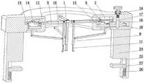
图2是本发明的全剖主视轴测图。FIG. 2 is a full-section front axonometric view of the present invention.
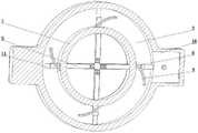
图3是本发明的全剖俯视轴测图。Figure 3 is a top isometric view of the present invention in full cutaway.
图4是本发明的环形齿轮的主视轴测图。Figure 4 is a front isometric view of the ring gear of the present invention.
图5是本发明的仰视轴测图。Figure 5 is a bottom axonometric view of the present invention.
图6是本发明的全剖仰视轴测图。Figure 6 is a bottom axonometric view of the present invention in full cutaway.
图7是本发明的全剖右视轴测图。Figure 7 is a full cut-away right axonometric view of the present invention.
图8是本发明图3中A的放大图。FIG. 8 is an enlarged view of A in FIG. 3 of the present invention.
图9是本发明图7中B的放大图。FIG. 9 is an enlarged view of B in FIG. 7 of the present invention.
具体实施方式Detailed ways
以下结合附图对本发明的具体实施方式作进一步详细说明。The specific embodiments of the present invention will be further described in detail below with reference to the accompanying drawings.
由图1至图9给出,包括上下轴向的圆形环1,圆形环1内同轴开设有环形槽2,环形槽2内同轴转动连接有环形齿轮3,环形齿轮3上侧设有多个沿其圆周方向均布的弧形板4,多个弧形板4与环形齿轮3圆心之间的距离沿顺时针方向逐渐变小,多个弧形板4的高度沿逆时针方向逐渐变高,环形槽2内滑动连接有多个与弧形板4一一对应且镜像方向的支撑板5,支撑板5外端伸入环形槽2内且其下侧开设有开口朝下的让位槽6,弧形板4位于其对应侧的让位槽6内,支撑板5可随环形齿轮3的转动而上下滑动,支撑板5内端贯穿圆形环1且开设有上下贯通的矩形槽7,矩形槽7内经销轴铰接有上下方向的撑杆8,圆形环1下侧设有多个与撑杆8一一对应且可滑动的连接块9,连接块9下端经连杆10与其对应侧的撑杆8外侧铰接连接,撑杆8下侧设有上下方向的手术拉钩11。1 to 9, it includes a
为了使支撑板5可随环形齿轮3的转动而上下滑动,所述的圆形环1上开设有多个与支撑板5一一对应且与环形槽2连通的辅助槽12,支撑板5位于其对应侧的辅助槽12内,环形槽2外侧壁上开设有多个与支撑板5一一对应且上下方向的导向槽13,导向槽13内滑动连接有导向板14,导向板14内端与其对应侧的支撑板5滑动连接。In order to enable the
为了使连接块9能够更好的滑动,所述的圆形环1下侧设有多个与撑杆8一一对应且镜像方向的滑槽15,连接块9位于其对应侧的滑槽15内且与滑槽15滑动连接。In order to enable the connecting
为了便于更好的转动环形齿轮3,所述的圆形环1右侧开设有与环形槽2连通的放置槽16,放置槽16内转动连接有上下轴向且开口朝上的导筒17,导筒17上同轴设有与环形齿轮3啮合的主动齿轮18,导筒17上端贯穿圆形环1且其内部套设有上下方向的T形转帽19,导筒17内同轴设有位于T形转帽19下侧的压簧。In order to facilitate better rotation of the
为了便于对导筒17的转动进行定位,所述的圆形环1上侧设有与导筒17同轴的导向环20,导向环20内下侧同轴开设有环形的转槽21,导向环20内侧开设有多个沿其圆周方向均布且上下方向的定位槽22,多个定位槽22均与转槽21上侧连通,T形转帽19外侧设有可沿定位槽22上下滑动且可沿转槽21转动的定位块23。In order to facilitate the positioning of the rotation of the
为了便于将圆形环1更好固定在手术台上,所述的圆形环1左右两侧分别设有上下方向的固定板24,固定板24内侧开设有开口朝下的固定槽25,固定槽25侧壁上开设有上下方向的滑道26,固定槽25内设有左右方向且可上下滑动的T形夹板27,T形夹板27外端伸入其对应侧的滑道26内且与滑道26滑动连接,T形夹板27下侧经上下轴向的弹簧28与滑道26滑动连接。In order to better fix the
为了使撑杆8在不受外力时能够保持竖直状态,所述的销轴上同轴设有位于矩形槽7内的扭簧29。In order to keep the
本发明在使用时,首先拉动T形夹板27沿滑道26向下滑动,弹簧28被压缩,随之将圆形环1经固定板24上的固定槽25卡接在手术台上,且使圆形环1位于患者创口处的正上方,随之不再拉动T形夹板27,此时在弹簧28的作用下,弹簧28带动T形夹板27沿滑道26向上滑动对手术台下侧进行挤压,便于将圆形环1稳定固定在手术台上,便于对患者的创口进行撑开避让,便于医护人员更好的进行手术;When the present invention is in use, first pull the T-
需要对患者创口进行撑开时,首先使多个手术拉钩11插入至患者的创口内,按压T形转帽19带动定位块23沿定位槽22向下移动插入至转槽21内,压簧被压缩,随之转动T形转帽19带动导筒17逆时针转动,导筒17经主动齿轮18带动环形齿轮3沿环形槽2顺时针转动,主动齿轮18顺时针转动经弧形板4和让位槽6带动多个支撑板5沿圆形环1向外滑动,促使支撑板5沿辅助槽12向外滑动并沿辅助槽12向上滑动,致使支撑板5带动导向板14沿导向槽13向上滑动,此时导向板14沿支撑板5向内滑动,促使支撑板5经撑杆8带动手术拉钩11向外并向上移动,促使手术拉钩11将患者的创口进行撑开,同时拉开患者的组织皮肤脱离器官组织,便于更好的进行手术,且撑杆8经连杆10推动连接块9沿滑槽15向外滑动,此时在扭簧29的作用下,能够使撑杆8保持竖直状态;When it is necessary to open the patient's wound, first insert a plurality of
当连接块9向外滑动与滑槽15的外侧接触时,支撑板5继续沿辅助槽12向外滑动,此时连接块9经连杆10推动撑杆8沿矩形槽7向内摆动,扭簧29收缩,促使撑杆8下端带动手术拉钩11下端向内摆动对患者的创口组织进行有效的分离,便于充分暴露手术部位进行手术治疗,将患者手术创口撑开牵拉完毕后,不再转动T形转帽19,此时在压簧的作用下,压簧推动T形转帽19带动定位块23沿转槽21向上移动插入至对应侧的定位槽22内,能够使导筒17处于稳定位置,便于使手术拉钩11保持稳定位置,便于对患者手术创口进行更好的撑开避让,便于患者医护人员进行手术;When the connecting
对患者手术完毕后,首先推动T形转帽19带动定位块23沿定位槽22向下移动插入至转槽21内,压簧被压缩,随之顺时针转动T形转帽19,T形转帽19经导筒17和主动齿轮18带动环形齿轮3逆时针转动,主动齿轮18逆时针转动经弧形板4和让位槽6带动多个支撑板5沿圆形环1向内滑动,促使支撑板5沿辅助槽12向内滑动并沿辅助槽12向下滑动,致使支撑板5带动导向板14沿导向槽13向下滑动,此时导向板14沿支撑板5向外滑动,促使支撑板5经撑杆8带动手术拉钩11向内并向下移动,促使手术拉钩11不再对患者的创口进行撑开和牵连,同时在扭簧29和支撑板5的作用下,促使手术拉钩11从倾斜状态摆动至竖直状态,随之将手术拉钩11从患者的创口处取出;After the operation on the patient, first push the T-shaped
将手术拉钩11从患者的创口处取出完毕后,首先拉动T形夹板27沿滑道26向下滑动,弹簧28被压缩,促使T形夹板27不再对手术台的下侧进行挤压固定,随之通过固定板24将圆形环1上的手术拉钩11从患者的身体上方移走,便于医护人员对患者手术后的创口进行缝合治疗,同时便于提高医护人员的工作效率。After removing the
本发明构思新颖,结构巧妙,操作方便,实用性强,设置的环形齿轮、弧形板、让位槽、支撑板、撑杆和手术拉钩,不仅便于通过环形齿轮的转动带动支撑板的内外滑动和上下滑动,从而便于通过撑杆带动手术拉钩对患者的创口进行撑开避让,同时也便于牵拉患者的组织皮肤脱离患者组织器官,便于更好的暴露手术视野,设有的连接块、连杆和扭簧,便于使手术拉钩能够进行倾斜,便于更好的暴露手术视野,设有的主动齿轮、导筒、定位块、转槽、定位槽和T形转帽,便于对手术拉钩的位置和角度进行限位,便于更好的对患者的创口进行撑开和避让,暴露手术视野,不仅提高了医护人员的工作效率,也便于对患者进行更好的手术治疗。The invention has novel conception, ingenious structure, convenient operation and strong practicability. The provided ring gear, arc-shaped plate, giving way slot, support plate, support rod and surgical hook are not only convenient for driving the support plate to slide inside and outside through the rotation of the ring gear and sliding up and down, so that the surgical retractor can be driven by the strut to open and avoid the patient's wound, and it is also convenient to pull the patient's tissue and skin away from the patient's tissue and organs, so as to better expose the surgical field. The rod and torsion spring are convenient for the surgical retractor to be tilted, which is convenient for better exposure of the surgical field. The drive gear, guide cylinder, positioning block, turning groove, positioning groove and T-shaped turning cap are provided to facilitate the positioning of the surgical retractor. And the angle is limited to facilitate better opening and avoidance of the patient's wound, exposing the surgical field of vision, which not only improves the work efficiency of medical staff, but also facilitates better surgical treatment of patients.
可见,利用本发明所提供的一种心脏手术创口支撑避让器,可以有效解决不便对患者创口有效的撑开避免和牵拉的问题,此结构操作简单,使用方便,便于对患者手术创口撑开避让,便于更好的手术治疗。It can be seen that the use of the heart surgery wound support and avoider provided by the present invention can effectively solve the problem of inconvenience to effectively open and stretch the patient's wound. Avoidance to facilitate better surgical treatment.
Claims (7)
Priority Applications (1)
| Application Number | Priority Date | Filing Date | Title |
|---|---|---|---|
| CN202210599818.4ACN114795332A (en) | 2022-05-30 | 2022-05-30 | Heart operation wound supports dodges ware |
Applications Claiming Priority (1)
| Application Number | Priority Date | Filing Date | Title |
|---|---|---|---|
| CN202210599818.4ACN114795332A (en) | 2022-05-30 | 2022-05-30 | Heart operation wound supports dodges ware |
Publications (1)
| Publication Number | Publication Date |
|---|---|
| CN114795332Atrue CN114795332A (en) | 2022-07-29 |
Family
ID=82519883
Family Applications (1)
| Application Number | Title | Priority Date | Filing Date |
|---|---|---|---|
| CN202210599818.4AWithdrawnCN114795332A (en) | 2022-05-30 | 2022-05-30 | Heart operation wound supports dodges ware |
Country Status (1)
| Country | Link |
|---|---|
| CN (1) | CN114795332A (en) |
Cited By (1)
| Publication number | Priority date | Publication date | Assignee | Title |
|---|---|---|---|---|
| CN115500882A (en)* | 2022-10-09 | 2022-12-23 | 中国人民解放军空军军医大学 | Special draw hook of thyroid surgery incision |
- 2022
- 2022-05-30CNCN202210599818.4Apatent/CN114795332A/ennot_activeWithdrawn
Cited By (2)
| Publication number | Priority date | Publication date | Assignee | Title |
|---|---|---|---|---|
| CN115500882A (en)* | 2022-10-09 | 2022-12-23 | 中国人民解放军空军军医大学 | Special draw hook of thyroid surgery incision |
| CN115500882B (en)* | 2022-10-09 | 2024-07-02 | 中国人民解放军空军军医大学 | Draw hook special for thyroid operation incision |
Similar Documents
| Publication | Publication Date | Title |
|---|---|---|
| CN105596040B (en) | TLIF operation path intervertebral opening devices | |
| CN112022280B (en) | Clinical stone device of getting of hepatobiliary surgery | |
| CN114795332A (en) | Heart operation wound supports dodges ware | |
| CN110368253A (en) | A kind of clinical obstetrics pre-natal diagnosis check device | |
| CN112043322B (en) | A sternum expander | |
| CN109953864A (en) | A kind of auxiliary support device for throat head and neck surgery | |
| CN209187386U (en) | A kind of gynaecology's lithotomy position examination bed | |
| CN209751004U (en) | An adjustable supporting device for eye examination | |
| CN116898504A (en) | A chest expansion device for extracardiac surgery | |
| CN106618648A (en) | Minitype universal surgical drag hook | |
| CN111227882B (en) | A claw mechanism for removing diseased tissue in the body | |
| CN108478265A (en) | A kind of novel gynecological vacuum extractor | |
| CN113288249A (en) | Hepatobiliary surgery is with propping solid device | |
| CN107233112A (en) | A kind of liver and gall surgical department operation pulling device | |
| CN108937835B (en) | Convenient adjustment type inspection desk of ophthalmic | |
| CN113558698A (en) | Angle adjusting structure of anorectal anastomat | |
| CN214208407U (en) | Surgical suture auxiliary device for surgical training | |
| CN216569899U (en) | An ophthalmic external eyelid opener | |
| CN117122359A (en) | Surgical field exposure device for adjusting and preventing tearing of spinal trauma site and use method | |
| CN215534253U (en) | Vaginal dilator with wing | |
| CN111214263A (en) | Eyelid distraction device for ophthalmologic nursing | |
| CN219846538U (en) | Adjustable anus dilator | |
| CN217244557U (en) | An anorectal surgical expansion rack | |
| CN218979578U (en) | A convenient support | |
| CN215457888U (en) | Adjustable vaginal dilator for cervical and vaginal operations of fat patients |
Legal Events
| Date | Code | Title | Description |
|---|---|---|---|
| PB01 | Publication | ||
| PB01 | Publication | ||
| SE01 | Entry into force of request for substantive examination | ||
| SE01 | Entry into force of request for substantive examination | ||
| WW01 | Invention patent application withdrawn after publication | ||
| WW01 | Invention patent application withdrawn after publication | Application publication date:20220729 |