CN114789561A - Aseptic connection of tubes - Google Patents
Aseptic connection of tubesDownload PDFInfo
- Publication number
- CN114789561A CN114789561ACN202210073604.3ACN202210073604ACN114789561ACN 114789561 ACN114789561 ACN 114789561ACN 202210073604 ACN202210073604 ACN 202210073604ACN 114789561 ACN114789561 ACN 114789561A
- Authority
- CN
- China
- Prior art keywords
- blade
- carrier
- move
- connection device
- proximal
- Prior art date
- Legal status (The legal status is an assumption and is not a legal conclusion. Google has not performed a legal analysis and makes no representation as to the accuracy of the status listed.)
- Granted
Links
- 238000005520cutting processMethods0.000claimsabstractdescription114
- 239000007787solidSubstances0.000claimsabstractdescription54
- 238000000034methodMethods0.000claimsabstractdescription41
- 238000010438heat treatmentMethods0.000claimsdescription79
- 239000000919ceramicSubstances0.000claimsdescription8
- RYGMFSIKBFXOCR-UHFFFAOYSA-NCopperChemical compound[Cu]RYGMFSIKBFXOCR-UHFFFAOYSA-N0.000claimsdescription7
- 229910052802copperInorganic materials0.000claimsdescription7
- 239000010949copperSubstances0.000claimsdescription7
- 239000012530fluidSubstances0.000description22
- 239000007788liquidSubstances0.000description14
- 230000007935neutral effectEffects0.000description13
- 239000003814drugSubstances0.000description11
- 239000000969carrierSubstances0.000description9
- 239000000306componentSubstances0.000description9
- 239000000463materialSubstances0.000description6
- 230000015654memoryEffects0.000description6
- 238000003825pressingMethods0.000description6
- 230000001954sterilising effectEffects0.000description6
- 238000005304joiningMethods0.000description5
- 230000007246mechanismEffects0.000description5
- 238000012545processingMethods0.000description5
- 238000004659sterilization and disinfectionMethods0.000description5
- 230000009471actionEffects0.000description4
- 230000013011matingEffects0.000description4
- 229940079593drugDrugs0.000description3
- 238000003032molecular dockingMethods0.000description3
- 229920003023plasticPolymers0.000description3
- 239000004033plasticSubstances0.000description3
- 230000008569processEffects0.000description3
- 238000007789sealingMethods0.000description3
- 239000008280bloodSubstances0.000description2
- 210000004369bloodAnatomy0.000description2
- 239000012503blood componentSubstances0.000description2
- 230000000694effectsEffects0.000description2
- 238000004519manufacturing processMethods0.000description2
- 239000012528membraneSubstances0.000description2
- 239000002184metalSubstances0.000description2
- 229910052751metalInorganic materials0.000description2
- 239000007769metal materialSubstances0.000description2
- 239000000843powderSubstances0.000description2
- 230000001225therapeutic effectEffects0.000description2
- IAYPIBMASNFSPL-UHFFFAOYSA-NEthylene oxideChemical compoundC1CO1IAYPIBMASNFSPL-UHFFFAOYSA-N0.000description1
- WQZGKKKJIJFFOK-GASJEMHNSA-NGlucoseNatural productsOC[C@H]1OC(O)[C@H](O)[C@@H](O)[C@@H]1OWQZGKKKJIJFFOK-GASJEMHNSA-N0.000description1
- FAPWRFPIFSIZLT-UHFFFAOYSA-MSodium chlorideChemical compound[Na+].[Cl-]FAPWRFPIFSIZLT-UHFFFAOYSA-M0.000description1
- 230000002411adverseEffects0.000description1
- 239000003146anticoagulant agentSubstances0.000description1
- 229940127219anticoagulant drugDrugs0.000description1
- 230000000712assemblyEffects0.000description1
- 238000000429assemblyMethods0.000description1
- 230000008901benefitEffects0.000description1
- 239000012620biological materialSubstances0.000description1
- 239000003795chemical substances by applicationSubstances0.000description1
- 238000002405diagnostic procedureMethods0.000description1
- 238000000502dialysisMethods0.000description1
- 238000007905drug manufacturingMethods0.000description1
- 238000010894electron beam technologyMethods0.000description1
- 239000008103glucoseSubstances0.000description1
- 238000003306harvestingMethods0.000description1
- 230000005865ionizing radiationEffects0.000description1
- 238000012986modificationMethods0.000description1
- 230000004048modificationEffects0.000description1
- 238000012544monitoring processMethods0.000description1
- 229920000915polyvinyl chloridePolymers0.000description1
- 239000004800polyvinyl chlorideSubstances0.000description1
- 238000004321preservationMethods0.000description1
- 238000003908quality control methodMethods0.000description1
- 230000005855radiationEffects0.000description1
- 239000011780sodium chlorideSubstances0.000description1
- 239000008223sterile waterSubstances0.000description1
- 238000003860storageMethods0.000description1
- 238000002560therapeutic procedureMethods0.000description1
- 238000012546transferMethods0.000description1
- 230000000007visual effectEffects0.000description1
- 239000002699waste materialSubstances0.000description1
- XLYOFNOQVPJJNP-UHFFFAOYSA-NwaterChemical compoundOXLYOFNOQVPJJNP-UHFFFAOYSA-N0.000description1
Images


Classifications
- B—PERFORMING OPERATIONS; TRANSPORTING
- B29—WORKING OF PLASTICS; WORKING OF SUBSTANCES IN A PLASTIC STATE IN GENERAL
- B29C—SHAPING OR JOINING OF PLASTICS; SHAPING OF MATERIAL IN A PLASTIC STATE, NOT OTHERWISE PROVIDED FOR; AFTER-TREATMENT OF THE SHAPED PRODUCTS, e.g. REPAIRING
- B29C65/00—Joining or sealing of preformed parts, e.g. welding of plastics materials; Apparatus therefor
- B29C65/74—Joining or sealing of preformed parts, e.g. welding of plastics materials; Apparatus therefor by welding and severing, or by joining and severing, the severing being performed in the area to be joined, next to the area to be joined, in the joint area or next to the joint area
- B29C65/743—Joining or sealing of preformed parts, e.g. welding of plastics materials; Apparatus therefor by welding and severing, or by joining and severing, the severing being performed in the area to be joined, next to the area to be joined, in the joint area or next to the joint area using the same tool for both joining and severing, said tool being monobloc or formed by several parts mounted together and forming a monobloc
- B—PERFORMING OPERATIONS; TRANSPORTING
- B29—WORKING OF PLASTICS; WORKING OF SUBSTANCES IN A PLASTIC STATE IN GENERAL
- B29C—SHAPING OR JOINING OF PLASTICS; SHAPING OF MATERIAL IN A PLASTIC STATE, NOT OTHERWISE PROVIDED FOR; AFTER-TREATMENT OF THE SHAPED PRODUCTS, e.g. REPAIRING
- B29C65/00—Joining or sealing of preformed parts, e.g. welding of plastics materials; Apparatus therefor
- B29C65/02—Joining or sealing of preformed parts, e.g. welding of plastics materials; Apparatus therefor by heating, with or without pressure
- B29C65/18—Joining or sealing of preformed parts, e.g. welding of plastics materials; Apparatus therefor by heating, with or without pressure using heated tools
- A—HUMAN NECESSITIES
- A61—MEDICAL OR VETERINARY SCIENCE; HYGIENE
- A61M—DEVICES FOR INTRODUCING MEDIA INTO, OR ONTO, THE BODY; DEVICES FOR TRANSDUCING BODY MEDIA OR FOR TAKING MEDIA FROM THE BODY; DEVICES FOR PRODUCING OR ENDING SLEEP OR STUPOR
- A61M39/00—Tubes, tube connectors, tube couplings, valves, access sites or the like, specially adapted for medical use
- A61M39/10—Tube connectors; Tube couplings
- A61M39/14—Tube connectors; Tube couplings for connecting tubes having sealed ends
- A61M39/146—Tube connectors; Tube couplings for connecting tubes having sealed ends by cutting and welding
- A—HUMAN NECESSITIES
- A61—MEDICAL OR VETERINARY SCIENCE; HYGIENE
- A61M—DEVICES FOR INTRODUCING MEDIA INTO, OR ONTO, THE BODY; DEVICES FOR TRANSDUCING BODY MEDIA OR FOR TAKING MEDIA FROM THE BODY; DEVICES FOR PRODUCING OR ENDING SLEEP OR STUPOR
- A61M39/00—Tubes, tube connectors, tube couplings, valves, access sites or the like, specially adapted for medical use
- A61M39/10—Tube connectors; Tube couplings
- A61M39/16—Tube connectors; Tube couplings having provision for disinfection or sterilisation
- A61M39/18—Methods or apparatus for making the connection under sterile conditions, i.e. sterile docking
- B—PERFORMING OPERATIONS; TRANSPORTING
- B29—WORKING OF PLASTICS; WORKING OF SUBSTANCES IN A PLASTIC STATE IN GENERAL
- B29C—SHAPING OR JOINING OF PLASTICS; SHAPING OF MATERIAL IN A PLASTIC STATE, NOT OTHERWISE PROVIDED FOR; AFTER-TREATMENT OF THE SHAPED PRODUCTS, e.g. REPAIRING
- B29C65/00—Joining or sealing of preformed parts, e.g. welding of plastics materials; Apparatus therefor
- B29C65/02—Joining or sealing of preformed parts, e.g. welding of plastics materials; Apparatus therefor by heating, with or without pressure
- B29C65/18—Joining or sealing of preformed parts, e.g. welding of plastics materials; Apparatus therefor by heating, with or without pressure using heated tools
- B29C65/20—Joining or sealing of preformed parts, e.g. welding of plastics materials; Apparatus therefor by heating, with or without pressure using heated tools with direct contact, e.g. using "mirror"
- B29C65/2046—Joining or sealing of preformed parts, e.g. welding of plastics materials; Apparatus therefor by heating, with or without pressure using heated tools with direct contact, e.g. using "mirror" using a welding mirror which also cuts the parts to be joined, e.g. for sterile welding
- B—PERFORMING OPERATIONS; TRANSPORTING
- B29—WORKING OF PLASTICS; WORKING OF SUBSTANCES IN A PLASTIC STATE IN GENERAL
- B29C—SHAPING OR JOINING OF PLASTICS; SHAPING OF MATERIAL IN A PLASTIC STATE, NOT OTHERWISE PROVIDED FOR; AFTER-TREATMENT OF THE SHAPED PRODUCTS, e.g. REPAIRING
- B29C65/00—Joining or sealing of preformed parts, e.g. welding of plastics materials; Apparatus therefor
- B29C65/02—Joining or sealing of preformed parts, e.g. welding of plastics materials; Apparatus therefor by heating, with or without pressure
- B29C65/18—Joining or sealing of preformed parts, e.g. welding of plastics materials; Apparatus therefor by heating, with or without pressure using heated tools
- B29C65/20—Joining or sealing of preformed parts, e.g. welding of plastics materials; Apparatus therefor by heating, with or without pressure using heated tools with direct contact, e.g. using "mirror"
- B29C65/2053—Joining or sealing of preformed parts, e.g. welding of plastics materials; Apparatus therefor by heating, with or without pressure using heated tools with direct contact, e.g. using "mirror" characterised by special ways of bringing the welding mirrors into position
- B29C65/2061—Joining or sealing of preformed parts, e.g. welding of plastics materials; Apparatus therefor by heating, with or without pressure using heated tools with direct contact, e.g. using "mirror" characterised by special ways of bringing the welding mirrors into position by sliding
- B29C65/2069—Joining or sealing of preformed parts, e.g. welding of plastics materials; Apparatus therefor by heating, with or without pressure using heated tools with direct contact, e.g. using "mirror" characterised by special ways of bringing the welding mirrors into position by sliding with an angle with respect to the plane comprising the parts to be joined
- B29C65/2076—Joining or sealing of preformed parts, e.g. welding of plastics materials; Apparatus therefor by heating, with or without pressure using heated tools with direct contact, e.g. using "mirror" characterised by special ways of bringing the welding mirrors into position by sliding with an angle with respect to the plane comprising the parts to be joined perpendicularly to the plane comprising the parts to be joined
- B—PERFORMING OPERATIONS; TRANSPORTING
- B29—WORKING OF PLASTICS; WORKING OF SUBSTANCES IN A PLASTIC STATE IN GENERAL
- B29C—SHAPING OR JOINING OF PLASTICS; SHAPING OF MATERIAL IN A PLASTIC STATE, NOT OTHERWISE PROVIDED FOR; AFTER-TREATMENT OF THE SHAPED PRODUCTS, e.g. REPAIRING
- B29C65/00—Joining or sealing of preformed parts, e.g. welding of plastics materials; Apparatus therefor
- B29C65/02—Joining or sealing of preformed parts, e.g. welding of plastics materials; Apparatus therefor by heating, with or without pressure
- B29C65/18—Joining or sealing of preformed parts, e.g. welding of plastics materials; Apparatus therefor by heating, with or without pressure using heated tools
- B29C65/24—Joining or sealing of preformed parts, e.g. welding of plastics materials; Apparatus therefor by heating, with or without pressure using heated tools characterised by the means for heating the tool
- B29C65/242—Joining or sealing of preformed parts, e.g. welding of plastics materials; Apparatus therefor by heating, with or without pressure using heated tools characterised by the means for heating the tool the heat transfer being achieved by contact, i.e. a heated tool being brought into contact with the welding tool and afterwards withdrawn from it
- B—PERFORMING OPERATIONS; TRANSPORTING
- B29—WORKING OF PLASTICS; WORKING OF SUBSTANCES IN A PLASTIC STATE IN GENERAL
- B29C—SHAPING OR JOINING OF PLASTICS; SHAPING OF MATERIAL IN A PLASTIC STATE, NOT OTHERWISE PROVIDED FOR; AFTER-TREATMENT OF THE SHAPED PRODUCTS, e.g. REPAIRING
- B29C65/00—Joining or sealing of preformed parts, e.g. welding of plastics materials; Apparatus therefor
- B29C65/74—Joining or sealing of preformed parts, e.g. welding of plastics materials; Apparatus therefor by welding and severing, or by joining and severing, the severing being performed in the area to be joined, next to the area to be joined, in the joint area or next to the joint area
- B29C65/745—Joining or sealing of preformed parts, e.g. welding of plastics materials; Apparatus therefor by welding and severing, or by joining and severing, the severing being performed in the area to be joined, next to the area to be joined, in the joint area or next to the joint area using a single unit having both a severing tool and a welding tool
- B—PERFORMING OPERATIONS; TRANSPORTING
- B29—WORKING OF PLASTICS; WORKING OF SUBSTANCES IN A PLASTIC STATE IN GENERAL
- B29C—SHAPING OR JOINING OF PLASTICS; SHAPING OF MATERIAL IN A PLASTIC STATE, NOT OTHERWISE PROVIDED FOR; AFTER-TREATMENT OF THE SHAPED PRODUCTS, e.g. REPAIRING
- B29C65/00—Joining or sealing of preformed parts, e.g. welding of plastics materials; Apparatus therefor
- B29C65/78—Means for handling the parts to be joined, e.g. for making containers or hollow articles, e.g. means for handling sheets, plates, web-like materials, tubular articles, hollow articles or elements to be joined therewith; Means for discharging the joined articles from the joining apparatus
- B29C65/7802—Positioning the parts to be joined, e.g. aligning, indexing or centring
- B—PERFORMING OPERATIONS; TRANSPORTING
- B29—WORKING OF PLASTICS; WORKING OF SUBSTANCES IN A PLASTIC STATE IN GENERAL
- B29C—SHAPING OR JOINING OF PLASTICS; SHAPING OF MATERIAL IN A PLASTIC STATE, NOT OTHERWISE PROVIDED FOR; AFTER-TREATMENT OF THE SHAPED PRODUCTS, e.g. REPAIRING
- B29C65/00—Joining or sealing of preformed parts, e.g. welding of plastics materials; Apparatus therefor
- B29C65/78—Means for handling the parts to be joined, e.g. for making containers or hollow articles, e.g. means for handling sheets, plates, web-like materials, tubular articles, hollow articles or elements to be joined therewith; Means for discharging the joined articles from the joining apparatus
- B29C65/7841—Holding or clamping means for handling purposes
- B—PERFORMING OPERATIONS; TRANSPORTING
- B29—WORKING OF PLASTICS; WORKING OF SUBSTANCES IN A PLASTIC STATE IN GENERAL
- B29C—SHAPING OR JOINING OF PLASTICS; SHAPING OF MATERIAL IN A PLASTIC STATE, NOT OTHERWISE PROVIDED FOR; AFTER-TREATMENT OF THE SHAPED PRODUCTS, e.g. REPAIRING
- B29C66/00—General aspects of processes or apparatus for joining preformed parts
- B29C66/001—Joining in special atmospheres
- B29C66/0012—Joining in special atmospheres characterised by the type of environment
- B29C66/0018—Joining in special atmospheres characterised by the type of environment being sterile
- B—PERFORMING OPERATIONS; TRANSPORTING
- B29—WORKING OF PLASTICS; WORKING OF SUBSTANCES IN A PLASTIC STATE IN GENERAL
- B29C—SHAPING OR JOINING OF PLASTICS; SHAPING OF MATERIAL IN A PLASTIC STATE, NOT OTHERWISE PROVIDED FOR; AFTER-TREATMENT OF THE SHAPED PRODUCTS, e.g. REPAIRING
- B29C66/00—General aspects of processes or apparatus for joining preformed parts
- B29C66/01—General aspects dealing with the joint area or with the area to be joined
- B29C66/02—Preparation of the material, in the area to be joined, prior to joining or welding
- B29C66/024—Thermal pre-treatments
- B29C66/0246—Cutting or perforating, e.g. burning away by using a laser or using hot air
- B—PERFORMING OPERATIONS; TRANSPORTING
- B29—WORKING OF PLASTICS; WORKING OF SUBSTANCES IN A PLASTIC STATE IN GENERAL
- B29C—SHAPING OR JOINING OF PLASTICS; SHAPING OF MATERIAL IN A PLASTIC STATE, NOT OTHERWISE PROVIDED FOR; AFTER-TREATMENT OF THE SHAPED PRODUCTS, e.g. REPAIRING
- B29C66/00—General aspects of processes or apparatus for joining preformed parts
- B29C66/01—General aspects dealing with the joint area or with the area to be joined
- B29C66/05—Particular design of joint configurations
- B29C66/10—Particular design of joint configurations particular design of the joint cross-sections
- B29C66/11—Joint cross-sections comprising a single joint-segment, i.e. one of the parts to be joined comprising a single joint-segment in the joint cross-section
- B29C66/114—Single butt joints
- B29C66/1142—Single butt to butt joints
- B—PERFORMING OPERATIONS; TRANSPORTING
- B29—WORKING OF PLASTICS; WORKING OF SUBSTANCES IN A PLASTIC STATE IN GENERAL
- B29C—SHAPING OR JOINING OF PLASTICS; SHAPING OF MATERIAL IN A PLASTIC STATE, NOT OTHERWISE PROVIDED FOR; AFTER-TREATMENT OF THE SHAPED PRODUCTS, e.g. REPAIRING
- B29C66/00—General aspects of processes or apparatus for joining preformed parts
- B29C66/50—General aspects of joining tubular articles; General aspects of joining long products, i.e. bars or profiled elements; General aspects of joining single elements to tubular articles, hollow articles or bars; General aspects of joining several hollow-preforms to form hollow or tubular articles
- B29C66/51—Joining tubular articles, profiled elements or bars; Joining single elements to tubular articles, hollow articles or bars; Joining several hollow-preforms to form hollow or tubular articles
- B29C66/52—Joining tubular articles, bars or profiled elements
- B29C66/522—Joining tubular articles
- B29C66/5221—Joining tubular articles for forming coaxial connections, i.e. the tubular articles to be joined forming a zero angle relative to each other
- B—PERFORMING OPERATIONS; TRANSPORTING
- B29—WORKING OF PLASTICS; WORKING OF SUBSTANCES IN A PLASTIC STATE IN GENERAL
- B29C—SHAPING OR JOINING OF PLASTICS; SHAPING OF MATERIAL IN A PLASTIC STATE, NOT OTHERWISE PROVIDED FOR; AFTER-TREATMENT OF THE SHAPED PRODUCTS, e.g. REPAIRING
- B29C66/00—General aspects of processes or apparatus for joining preformed parts
- B29C66/70—General aspects of processes or apparatus for joining preformed parts characterised by the composition, physical properties or the structure of the material of the parts to be joined; Joining with non-plastics material
- B29C66/73—General aspects of processes or apparatus for joining preformed parts characterised by the composition, physical properties or the structure of the material of the parts to be joined; Joining with non-plastics material characterised by the intensive physical properties of the material of the parts to be joined, by the optical properties of the material of the parts to be joined, by the extensive physical properties of the parts to be joined, by the state of the material of the parts to be joined or by the material of the parts to be joined being a thermoplastic or a thermoset
- B29C66/737—General aspects of processes or apparatus for joining preformed parts characterised by the composition, physical properties or the structure of the material of the parts to be joined; Joining with non-plastics material characterised by the intensive physical properties of the material of the parts to be joined, by the optical properties of the material of the parts to be joined, by the extensive physical properties of the parts to be joined, by the state of the material of the parts to be joined or by the material of the parts to be joined being a thermoplastic or a thermoset characterised by the state of the material of the parts to be joined
- B29C66/7373—Joining soiled or oxidised materials
- B—PERFORMING OPERATIONS; TRANSPORTING
- B29—WORKING OF PLASTICS; WORKING OF SUBSTANCES IN A PLASTIC STATE IN GENERAL
- B29C—SHAPING OR JOINING OF PLASTICS; SHAPING OF MATERIAL IN A PLASTIC STATE, NOT OTHERWISE PROVIDED FOR; AFTER-TREATMENT OF THE SHAPED PRODUCTS, e.g. REPAIRING
- B29C66/00—General aspects of processes or apparatus for joining preformed parts
- B29C66/80—General aspects of machine operations or constructions and parts thereof
- B29C66/81—General aspects of the pressing elements, i.e. the elements applying pressure on the parts to be joined in the area to be joined, e.g. the welding jaws or clamps
- B29C66/816—General aspects of the pressing elements, i.e. the elements applying pressure on the parts to be joined in the area to be joined, e.g. the welding jaws or clamps characterised by the mounting of the pressing elements, e.g. of the welding jaws or clamps
- B29C66/8167—Quick change joining tools or surfaces
- B—PERFORMING OPERATIONS; TRANSPORTING
- B29—WORKING OF PLASTICS; WORKING OF SUBSTANCES IN A PLASTIC STATE IN GENERAL
- B29C—SHAPING OR JOINING OF PLASTICS; SHAPING OF MATERIAL IN A PLASTIC STATE, NOT OTHERWISE PROVIDED FOR; AFTER-TREATMENT OF THE SHAPED PRODUCTS, e.g. REPAIRING
- B29C66/00—General aspects of processes or apparatus for joining preformed parts
- B29C66/80—General aspects of machine operations or constructions and parts thereof
- B29C66/84—Specific machine types or machines suitable for specific applications
- B29C66/857—Medical tube welding machines
- B—PERFORMING OPERATIONS; TRANSPORTING
- B29—WORKING OF PLASTICS; WORKING OF SUBSTANCES IN A PLASTIC STATE IN GENERAL
- B29C—SHAPING OR JOINING OF PLASTICS; SHAPING OF MATERIAL IN A PLASTIC STATE, NOT OTHERWISE PROVIDED FOR; AFTER-TREATMENT OF THE SHAPED PRODUCTS, e.g. REPAIRING
- B29C66/00—General aspects of processes or apparatus for joining preformed parts
- B29C66/90—Measuring or controlling the joining process
- B29C66/91—Measuring or controlling the joining process by measuring or controlling the temperature, the heat or the thermal flux
- B29C66/912—Measuring or controlling the joining process by measuring or controlling the temperature, the heat or the thermal flux by measuring the temperature, the heat or the thermal flux
- B29C66/9121—Measuring or controlling the joining process by measuring or controlling the temperature, the heat or the thermal flux by measuring the temperature, the heat or the thermal flux by measuring the temperature
- B29C66/91211—Measuring or controlling the joining process by measuring or controlling the temperature, the heat or the thermal flux by measuring the temperature, the heat or the thermal flux by measuring the temperature with special temperature measurement means or methods
- B29C66/91212—Measuring or controlling the joining process by measuring or controlling the temperature, the heat or the thermal flux by measuring the temperature, the heat or the thermal flux by measuring the temperature with special temperature measurement means or methods involving measurement means being part of the welding jaws, e.g. integrated in the welding jaws
- B—PERFORMING OPERATIONS; TRANSPORTING
- B29—WORKING OF PLASTICS; WORKING OF SUBSTANCES IN A PLASTIC STATE IN GENERAL
- B29C—SHAPING OR JOINING OF PLASTICS; SHAPING OF MATERIAL IN A PLASTIC STATE, NOT OTHERWISE PROVIDED FOR; AFTER-TREATMENT OF THE SHAPED PRODUCTS, e.g. REPAIRING
- B29C66/00—General aspects of processes or apparatus for joining preformed parts
- B29C66/90—Measuring or controlling the joining process
- B29C66/91—Measuring or controlling the joining process by measuring or controlling the temperature, the heat or the thermal flux
- B29C66/912—Measuring or controlling the joining process by measuring or controlling the temperature, the heat or the thermal flux by measuring the temperature, the heat or the thermal flux
- B29C66/9121—Measuring or controlling the joining process by measuring or controlling the temperature, the heat or the thermal flux by measuring the temperature, the heat or the thermal flux by measuring the temperature
- B29C66/91231—Measuring or controlling the joining process by measuring or controlling the temperature, the heat or the thermal flux by measuring the temperature, the heat or the thermal flux by measuring the temperature of the joining tool
- B—PERFORMING OPERATIONS; TRANSPORTING
- B29—WORKING OF PLASTICS; WORKING OF SUBSTANCES IN A PLASTIC STATE IN GENERAL
- B29C—SHAPING OR JOINING OF PLASTICS; SHAPING OF MATERIAL IN A PLASTIC STATE, NOT OTHERWISE PROVIDED FOR; AFTER-TREATMENT OF THE SHAPED PRODUCTS, e.g. REPAIRING
- B29C66/00—General aspects of processes or apparatus for joining preformed parts
- B29C66/90—Measuring or controlling the joining process
- B29C66/91—Measuring or controlling the joining process by measuring or controlling the temperature, the heat or the thermal flux
- B29C66/914—Measuring or controlling the joining process by measuring or controlling the temperature, the heat or the thermal flux by controlling or regulating the temperature, the heat or the thermal flux
- B29C66/9141—Measuring or controlling the joining process by measuring or controlling the temperature, the heat or the thermal flux by controlling or regulating the temperature, the heat or the thermal flux by controlling or regulating the temperature
- B29C66/91421—Measuring or controlling the joining process by measuring or controlling the temperature, the heat or the thermal flux by controlling or regulating the temperature, the heat or the thermal flux by controlling or regulating the temperature of the joining tools
- B—PERFORMING OPERATIONS; TRANSPORTING
- B29—WORKING OF PLASTICS; WORKING OF SUBSTANCES IN A PLASTIC STATE IN GENERAL
- B29C—SHAPING OR JOINING OF PLASTICS; SHAPING OF MATERIAL IN A PLASTIC STATE, NOT OTHERWISE PROVIDED FOR; AFTER-TREATMENT OF THE SHAPED PRODUCTS, e.g. REPAIRING
- B29C66/00—General aspects of processes or apparatus for joining preformed parts
- B29C66/90—Measuring or controlling the joining process
- B29C66/92—Measuring or controlling the joining process by measuring or controlling the pressure, the force, the mechanical power or the displacement of the joining tools
- B29C66/924—Measuring or controlling the joining process by measuring or controlling the pressure, the force, the mechanical power or the displacement of the joining tools by controlling or regulating the pressure, the force, the mechanical power or the displacement of the joining tools
- B29C66/9261—Measuring or controlling the joining process by measuring or controlling the pressure, the force, the mechanical power or the displacement of the joining tools by controlling or regulating the pressure, the force, the mechanical power or the displacement of the joining tools by controlling or regulating the displacement of the joining tools
- F—MECHANICAL ENGINEERING; LIGHTING; HEATING; WEAPONS; BLASTING
- F16—ENGINEERING ELEMENTS AND UNITS; GENERAL MEASURES FOR PRODUCING AND MAINTAINING EFFECTIVE FUNCTIONING OF MACHINES OR INSTALLATIONS; THERMAL INSULATION IN GENERAL
- F16L—PIPES; JOINTS OR FITTINGS FOR PIPES; SUPPORTS FOR PIPES, CABLES OR PROTECTIVE TUBING; MEANS FOR THERMAL INSULATION IN GENERAL
- F16L47/00—Connecting arrangements or other fittings specially adapted to be made of plastics or to be used with pipes made of plastics
- F16L47/02—Welded joints; Adhesive joints
- G—PHYSICS
- G05—CONTROLLING; REGULATING
- G05D—SYSTEMS FOR CONTROLLING OR REGULATING NON-ELECTRIC VARIABLES
- G05D23/00—Control of temperature
- G05D23/19—Control of temperature characterised by the use of electric means
- G05D23/20—Control of temperature characterised by the use of electric means with sensing elements having variation of electric or magnetic properties with change of temperature
- G05D23/22—Control of temperature characterised by the use of electric means with sensing elements having variation of electric or magnetic properties with change of temperature the sensing element being a thermocouple
- B—PERFORMING OPERATIONS; TRANSPORTING
- B29—WORKING OF PLASTICS; WORKING OF SUBSTANCES IN A PLASTIC STATE IN GENERAL
- B29C—SHAPING OR JOINING OF PLASTICS; SHAPING OF MATERIAL IN A PLASTIC STATE, NOT OTHERWISE PROVIDED FOR; AFTER-TREATMENT OF THE SHAPED PRODUCTS, e.g. REPAIRING
- B29C66/00—General aspects of processes or apparatus for joining preformed parts
- B29C66/70—General aspects of processes or apparatus for joining preformed parts characterised by the composition, physical properties or the structure of the material of the parts to be joined; Joining with non-plastics material
- B29C66/71—General aspects of processes or apparatus for joining preformed parts characterised by the composition, physical properties or the structure of the material of the parts to be joined; Joining with non-plastics material characterised by the composition of the plastics material of the parts to be joined
- B—PERFORMING OPERATIONS; TRANSPORTING
- B29—WORKING OF PLASTICS; WORKING OF SUBSTANCES IN A PLASTIC STATE IN GENERAL
- B29L—INDEXING SCHEME ASSOCIATED WITH SUBCLASS B29C, RELATING TO PARTICULAR ARTICLES
- B29L2023/00—Tubular articles
- B29L2023/005—Hoses, i.e. flexible
- B29L2023/007—Medical tubes other than catheters
- B—PERFORMING OPERATIONS; TRANSPORTING
- B29—WORKING OF PLASTICS; WORKING OF SUBSTANCES IN A PLASTIC STATE IN GENERAL
- B29L—INDEXING SCHEME ASSOCIATED WITH SUBCLASS B29C, RELATING TO PARTICULAR ARTICLES
- B29L2031/00—Other particular articles
- B29L2031/753—Medical equipment; Accessories therefor
Landscapes
- Engineering & Computer Science (AREA)
- Mechanical Engineering (AREA)
- Health & Medical Sciences (AREA)
- Physics & Mathematics (AREA)
- Thermal Sciences (AREA)
- Heart & Thoracic Surgery (AREA)
- General Engineering & Computer Science (AREA)
- Pulmonology (AREA)
- Life Sciences & Earth Sciences (AREA)
- Veterinary Medicine (AREA)
- Toxicology (AREA)
- Anesthesiology (AREA)
- Biomedical Technology (AREA)
- Hematology (AREA)
- Public Health (AREA)
- Animal Behavior & Ethology (AREA)
- General Health & Medical Sciences (AREA)
- Automation & Control Theory (AREA)
- General Physics & Mathematics (AREA)
- Epidemiology (AREA)
- Infusion, Injection, And Reservoir Apparatuses (AREA)
- External Artificial Organs (AREA)
Abstract
Translated fromChinese
Description
Translated fromChinese相关申请的交叉引用CROSS-REFERENCE TO RELATED APPLICATIONS
本申请要求于2021年1月25日提交的序列号为63/140,995的美国临时专利申请的权益和优先权,该美国临时专利申请的内容通过参引并入本文中。This application claims the benefit of and priority to US Provisional Patent Application Serial No. 63/140,995, filed January 25, 2021, the contents of which are incorporated herein by reference.
技术领域technical field
本发明涉及管的接合。更具体地,本发明涉及用于无菌地接合管的系统和方法。The present invention relates to the joining of pipes. More particularly, the present invention relates to systems and methods for aseptically joining tubes.
背景技术Background technique
预灭菌和/或预组装的流体流动系统或组件广泛用于各种医疗和非医疗应用。例如,医疗应用可以包括出于治疗和/或诊断目的向患者施用医用流体、血液和/或血液成分或其他细胞采集或处理、透析和其他医疗程序。这些系统或组件的非医疗应用可以包括例如药物制造和细胞处理。特别是在医疗领域,这些流动系统通常采用一个或更多个预填充容器或其他医用流体或药剂源以及包含必要的流管、阀门、流量控制器、处理室等的相关的流体流动回路或系统(有时称为管组)单独地或者与可重复使用的控制器或其他装置相配合地来执行特定的程序。例如,医疗流体流动系统包括下述各者个容器或者与下述各者的容器相关联地使用并不罕见:适合的药物、生理盐水、抗凝血剂、葡萄糖溶液、无菌水、细胞防腐剂等,此处仅举几个示例。Pre-sterilized and/or pre-assembled fluid flow systems or assemblies are used in a wide variety of medical and non-medical applications. For example, medical applications may include administration of medical fluids, blood and/or blood components or other cell harvesting or processing, dialysis and other medical procedures to a patient for therapeutic and/or diagnostic purposes. Non-medical applications of these systems or components can include, for example, drug manufacturing and cell processing. Particularly in the medical field, these flow systems typically employ one or more pre-filled containers or other sources of medical fluid or medicament and associated fluid flow circuits or systems containing the necessary flow tubes, valves, flow controllers, process chambers, etc. (sometimes referred to as a tube pack) alone or in conjunction with a reusable controller or other device to carry out a particular program. For example, it is not uncommon for medical fluid flow systems to include, or be used in association with, containers of suitable drugs, saline, anticoagulants, glucose solutions, sterile water, cell preservation agents, etc., just to name a few examples.
然而,由于各种原因,这种流体流动系统可能会给制造或组装带来挑战。一个原因可能是,给患者施用或者在医用流体流动系统中采用的医用液体、药粉或其他药剂的预填充容器与流体流动系统的其他部分相比需要不同的灭菌技术。例如,不包含任何大量的液体或其他药剂的空塑料管、容器、流量控制装置和/或处理装置或室可以利用伽马辐射或电子束辐(e-beam)射或者通过暴露于灭菌气体、例如环氧乙烷进行灭菌。然而,气体灭菌将对灭菌包含在密封容器中的药剂比如液体、药粉或药物将是无效的,并且将药剂暴露于电离辐射可能会使药剂降解或者以其他方式对药剂产生有害影响。另外,可能存在下述情况:即使适用于相同的灭菌过程,无菌流体流动系统的不同部分也会因其他原因而分开制造和灭菌并且随后以无菌方式组装。However, such fluid flow systems can present manufacturing or assembly challenges for a variety of reasons. One reason may be that prefilled containers of medical liquids, powders, or other medicaments administered to a patient or employed in a medical fluid flow system require different sterilization techniques than the rest of the fluid flow system. For example, empty plastic tubes, containers, flow control devices, and/or processing devices or chambers that do not contain any bulk liquid or other medicament may be irradiated with gamma or electron beam (e-beam) radiation or by exposure to sterile gas , such as ethylene oxide for sterilization. However, gas sterilization will be ineffective in sterilizing the medicament contained in a sealed container, such as a liquid, powder or drug, and exposing the medicament to ionizing radiation may degrade or otherwise adversely affect the medicament. In addition, there may be situations where different parts of a sterile fluid flow system are manufactured and sterilized separately for other reasons and then assembled in a sterile manner, even if applicable to the same sterilization process.
此外,无菌连接通常需要由最终使用者在现场进行,例如在流体流动系统被用于治疗患者或采集或处理血液或血液成分或生物材料的位置处,或在其他治疗或诊断程序中。因此,许多不同的方法已经被用于组装无菌流体流动系统。例如,制造这种系统的一种技术采用了无菌对接系统,比如在美国专利No.4,157,723中公开的装置,该美国专利在此通过参引并入本文中。如在该美国专利中图示的,无菌对接系统包括各自具有饰面膜的一对配合构件。配合构件中的一个配合构件连接至液体、药物或其他药剂的预先灭菌的容器并且另一配合构件附接至预先灭菌的流体流动系统,该流体流动系统可以包括一个或更多个空容器。在两个构件接合之后,对接系统暴露于辐射能,从而使膜融合并且通过配合构件形成无菌液体路径。流体然后可以从初始容器转移到流体流动系统中的空容器中,并且流动路径被密封和切断。然后初始容器和配合构件被丢弃。虽然该方法的效果令人满意,但它需要以无菌的方式将溶液从一个容器转移至另一容器的多个制造步骤以及与此步骤相关的质量控制程序。它还需要处理产品的一部分,这增加了产品和浪费成本。Furthermore, sterile connections are often required to be made in the field by the end user, such as where the fluid flow system is used to treat a patient or collect or process blood or blood components or biological materials, or in other therapeutic or diagnostic procedures. Therefore, many different methods have been used to assemble sterile fluid flow systems. For example, one technique for making such a system employs a sterile docking system, such as the device disclosed in US Patent No. 4,157,723, which is incorporated herein by reference. As illustrated in this US patent, the sterile docking system includes a pair of mating members each having a facing membrane. One of the mating members is connected to a pre-sterilized container of liquid, drug or other medicament and the other is attached to a pre-sterilized fluid flow system, which may include one or more empty containers . After the two members are engaged, the docking system is exposed to radiant energy, thereby fusing the membranes and forming a sterile fluid path through the mating members. The fluid can then be transferred from the initial container to an empty container in the fluid flow system, and the flow path sealed and cut off. The initial container and mating member are then discarded. While this method works satisfactorily, it requires multiple manufacturing steps to transfer the solution from one container to another in a sterile manner and the quality control procedures associated with this step. It also needs to dispose of part of the product, which increases product and waste costs.
根据在美国专利No.4,978,446(该美国专利在此通过参引并入本文中)中所描述的替代性方法,在将预先灭菌的液体容器等联接至分开灭菌的流体流动管系统的入口流动管路上使用灭菌过滤器。在这种方法中,医务人员需要手动地将流体流动管系统接合至流体容器,比如通过利用与流体流动系统相关联的刺穿构件将流体容器刺穿。除了对于单独订购、存储、以及处方溶液和一次性流动系统或套件的管理要求之外,还存在附加失误的可能性,比如通过连接不正确的液体或其他药剂的容器或待使用的与程序相关联的不适当的流动系统。According to an alternative method described in US Pat. No. 4,978,446, which is hereby incorporated by reference, a pre-sterilized liquid container or the like is coupled to the inlet of a separately sterilized fluid flow tubing system. Use sterile filters on the flow lines. In this method, medical personnel need to manually engage the fluid flow tubing system to the fluid container, such as by piercing the fluid container with a piercing member associated with the fluid flow system. In addition to the separate ordering, storage, and administrative requirements for prescription solutions and disposable flow systems or kits, there is the potential for additional errors, such as by connecting incorrect containers of liquids or other medicaments or procedures related to the ones to be used. Inappropriate flow system connected.
另外,存在通常被称为无菌管焊机的已知装置,其中以由泰尔茂医疗公司(TerumoMedical Corporation)销售的装置TSCD-II无菌管焊机作为一个示例。该装置使用加热的切割元件来切割并且融合管的端部,管的端部在移除切割元件后接合在一起。该装置的各方面在美国专利申请公开No.2020/0047423中被公开,该美国专利在此通过参引并入本文中。该装置的一个显著的缺点是,它需要使用昂贵的切割元件(每个切割元件包括置于两个铜层之间的电阻电路层),这些切割元件在每次拼接后被更换。In addition, there are known devices commonly referred to as sterile tube welders, of which the device TSCD-II sterile tube welder sold by Terumo Medical Corporation is exemplified. The device uses a heated cutting element to cut and fuse the ends of the tube, which are joined together after the cutting element is removed. Aspects of this device are disclosed in US Patent Application Publication No. 2020/0047423, which is incorporated herein by reference. A significant disadvantage of this device is that it requires the use of expensive cutting elements (each including a resistive circuit layer placed between two copper layers) which are replaced after each splicing.
因此,在该领域仍然需要进步。Therefore, progress is still required in this field.
发明内容SUMMARY OF THE INVENTION
本主题存在若干方面,这些方面可以在下面所描述和所要求保护的装置和系统中单独地或一起地实施。这些方面可以单独地或者与本文中所描述的主题的其他方面组合地采用,并且对这些方面一起描述并不意在排除如本文所附权利要求中所阐明的单独使用这些方面或者单独地或以不同的组合来要求保护这些方面。There are several aspects of the subject matter that can be implemented separately or together in the apparatus and systems described and claimed below. These aspects may be employed alone or in combination with other aspects of the subject matter described herein, and the description of these aspects together is not intended to preclude the use of these aspects alone or alone or in different ways, as set forth in the claims appended hereto. combination to claim protection of these aspects.
在一个方面,无菌连接装置包括壳体以及第一承载件和第二承载件。第一承载件包括下夹爪,该下夹爪限定近端槽的第一部分并且限定远端槽的第一部分,所述近端槽构造成接纳近端密封管的一部分,所述远端槽构造成接纳远端密封管的一部分。第一承载件还包括上夹爪,该上夹爪构造成在与下夹爪间隔开的打开状态与邻近下夹爪定位的闭合状态之间移动。第二承载件定位在第一承载件的侧向并且包括下夹爪和上夹爪,下夹爪限定近端槽的第二部分和远端槽的第二部分,上夹爪构造成在与下夹爪间隔开的打开状态与邻近下夹爪定位的闭合状态之间移动。无菌连接装置还包括刀片处理组件、刀片加热组件和系统控制器。系统控制器配置成在近端管和远端管被近端槽和远端槽接纳并且上夹爪处于其闭合状态时执行无菌连接程序。该程序包括将刀片加热组件控制成通过传导加热对实心切割刀片进行加热、将刀片处理组件控制成使经加热的刀片移动至切割位置以便切割近端管和远端管、以及将第二承载件控制成相对于第一承载件向近端或远端移动以便使近端槽的所述部分中的一者与远端槽的所述部分中的一者对准。系统控制器然后将刀片处理组件控制成使经加热的刀片前进离开切割位置,随后将第一承载件控制成朝向第二承载件侧向地移动以便将近端管和远端管的由近端槽和远端槽的对准部分接纳的切割端部按压成彼此接触从而将切割端部无菌地连接并且限定接合管。In one aspect, a sterile connection device includes a housing and first and second carriers. The first carrier includes a lower jaw that defines a first portion of a proximal slot and defines a first portion of a distal slot configured to receive a portion of a proximal seal tube, the distal slot configured to receive a portion of the distal sealing tube. The first carrier also includes an upper jaw configured to move between an open state spaced from the lower jaw and a closed state positioned adjacent the lower jaw. The second carrier is positioned laterally of the first carrier and includes a lower jaw and an upper jaw, the lower jaw defining a second portion of the proximal slot and a second portion of the distal slot, the upper jaw configured to be in contact with the Moves between an open state in which the lower jaws are spaced apart and a closed state in which the lower jaws are positioned adjacent to the lower jaws. The sterile connection device also includes a blade handling assembly, a blade heating assembly, and a system controller. The system controller is configured to perform the aseptic connection procedure when the proximal and distal tubes are received by the proximal and distal slots and the upper jaws are in their closed state. The procedure includes controlling the blade heating assembly to heat the solid cutting blade by conduction heating, controlling the blade handling assembly to move the heated blade to the cutting position for cutting the proximal and distal tubes, and the second carrier Controlled to move proximally or distally relative to the first carrier to align one of the portions of the proximal slot with one of the portions of the distal slot. The system controller then controls the blade handling assembly to advance the heated blade away from the cutting position, and then controls the first carrier to move laterally toward the second carrier for proximal and distal movement of the proximal and distal tubes. The cut ends received by the aligned portions of the slot and distal slot are pressed into contact with each other to aseptically connect the cut ends and define an engagement tube.
在另一方面,无菌连接装置包括壳体以及第一承载件和第二承载件。第一承载件包括下夹爪,该下夹爪限定近端槽的第一部分并且限定远端槽的第一部分,近端槽构造成接纳近端密封管的一部分,远端槽接纳远端密封管的一部分。第一承载件还包括上夹爪,该上夹爪构造成在与下夹爪间隔开的打开状态与邻近下夹爪定位的闭合状态之间移动。第二承载件定位在第一承载件的侧向并且包括下夹爪和上夹爪,下夹爪限定近端槽的第二部分和远端槽的第二部分,上夹爪构造成在与下夹爪间隔开的打开状态与邻近下夹爪定位的闭合状态之间移动。无菌连接装置还包括刀片处理组件、刀片加热组件和系统控制器。系统控制器配置成在近端管和远端管被近端槽和远端槽接纳并且上夹爪处于它们的闭合状态时执行无菌连接程序。该程序包括将刀片加热组件控制成使用陶瓷加热元件对实心切割刀片进行加热、将刀片处理组件控制成使经加热的刀片移动至切割位置以便切割近端管和远端管、以及将第二承载件控制成相对于第一承载件向近端或远端移动以便使近端槽的所述部分中的一者与远端槽的所述部分中的一者对准。系统控制器然后将刀片处理组件控制成使经加热的刀片前进离开切割位置,随后将第一承载件控制成朝向第二承载件侧向移动以便将近端管和远端管的由近端槽和远端槽的对准部分接纳的切割端部按压成彼此接触从而将切割端部无菌地连接并且限定接合管。In another aspect, a sterile connection device includes a housing and first and second carriers. The first carrier includes a lower jaw that defines a first portion of a proximal slot and defines a first portion of a distal slot, the proximal slot configured to receive a portion of the proximal seal tube, the distal slot receiving the distal seal tube a part of. The first carrier also includes an upper jaw configured to move between an open state spaced from the lower jaw and a closed state positioned adjacent the lower jaw. The second carrier is positioned laterally of the first carrier and includes a lower jaw and an upper jaw, the lower jaw defining a second portion of the proximal slot and a second portion of the distal slot, the upper jaw configured to be in contact with the Moves between an open state in which the lower jaws are spaced apart and a closed state in which the lower jaws are positioned adjacent to the lower jaws. The sterile connection device also includes a blade handling assembly, a blade heating assembly, and a system controller. The system controller is configured to perform the aseptic connection procedure when the proximal and distal tubes are received by the proximal and distal slots and the upper jaws are in their closed states. The procedure includes controlling the blade heating assembly to heat the solid cutting blade using the ceramic heating element, controlling the blade handling assembly to move the heated blade to the cutting position for cutting the proximal and distal tubes, and placing the second carrier The member is controlled to move proximally or distally relative to the first carrier to align one of the portions of the proximal slot with one of the portions of the distal slot. The system controller then controls the blade handling assembly to advance the heated blade away from the cutting position, and then controls the first carrier to move laterally toward the second carrier to allow the proximal and distal tubes to be separated by the proximal slots. The cutting ends received by the aligned portions of the distal slot are pressed into contact with each other to aseptically connect the cutting ends and define the engagement tube.
附图说明Description of drawings
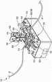
图1是根据本公开的一方面的无菌连接装置的立体图,其中,该装置的上夹爪处于闭合状态;1 is a perspective view of a sterile connection device according to an aspect of the present disclosure, wherein the upper jaws of the device are in a closed state;
图2和图3是图1的无菌连接装置的立体图,其中,该装置的上夹爪处于打开状态;Figures 2 and 3 are perspective views of the aseptic connection device of Figure 1 with the upper jaws of the device in an open state;
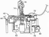
图4至图6是图1的无菌连接装置的立体图,其中,为了说明性目的,该装置的不同部分被剖开或省略;Figures 4-6 are perspective views of the sterile connection device of Figure 1 with various parts of the device cut away or omitted for illustrative purposes;
图7是与图1的无菌连接装置组合使用的一次性刀片的俯视平面图;Figure 7 is a top plan view of a disposable blade used in combination with the sterile connection device of Figure 1;
图8是构造成用于分配图7中所示的类型刀片的刀片盒的侧视图;Figure 8 is a side view of a blade cartridge configured for dispensing blades of the type shown in Figure 7;
图9是图8的刀片盒的立体图;Figure 9 is a perspective view of the blade cartridge of Figure 8;
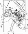
图10是根据本公开的无菌连接装置的另一示例性实施方式的立体图,其中,该装置的第一承载件和第二承载件对准并且承载件的上夹爪处于打开状态;10 is a perspective view of another exemplary embodiment of a sterile connection device in accordance with the present disclosure, wherein the first and second carriers of the device are aligned and the upper jaws of the carriers are in an open state;
图11是图10的无菌连接装置的立体图,其中,第一承载件和第二承载件的上夹爪处于闭合状态;Figure 11 is a perspective view of the aseptic connection device of Figure 10, wherein the upper jaws of the first carrier and the second carrier are in a closed state;
图12是图10的无菌连接装置的立体图,其中,第一承载件和第二承载件脱离对准并且上夹爪处于它们的闭合状态;以及Figure 12 is a perspective view of the sterile connection device of Figure 10 with the first and second carriers out of alignment and the upper jaws in their closed state; and
图13为图10的无菌连接装置的立体图,其中,第一承载件和第二承载件脱离对准并且上夹爪处于它们的打开状态。Figure 13 is a perspective view of the sterile connection device of Figure 10 with the first and second carriers out of alignment and the upper jaws in their open state.
具体实施方式Detailed ways
本文中所公开的各实施方式是为了提供本主题的描述的目的,并且应当理解的是,本主题可以以未详细示出的多种其他形式和组合来实现。因此,本文中所公开的各具体设计和特征不应被解释为限制如在所附权利要求中所限定的主题。The embodiments disclosed herein are for the purpose of providing a description of the subject matter, and it is to be understood that the subject matter may be embodied in various other forms and combinations not shown in detail. Therefore, the specific designs and features disclosed herein are not to be interpreted as limiting the subject matter as defined in the appended claims.
图1至图3图示了根据本公开的一方面的无菌连接装置10的示例性实施方式,而图4至图6图示了其中为了说明性目的而将其各种部分被剖开或省略的无菌连接装置10。虽然根据本公开的无菌连接装置特别适合于由聚氯乙烯形成的管的无菌连接,但用于无菌连接由其他材料形成的管的无菌连接装置10也在本公开的范围内。FIGS. 1-3 illustrate an exemplary embodiment of a
图示的无菌连接装置10包括壳体12,壳体12容纳无菌连接装置12的各个部件。壳体12可以在不脱离本公开的范围的情况下以各种方式进行构造,这可以包括具有由例如金属材料、塑料材料或金属和塑料材料的组合形成的不同部分的壳体12。The illustrated
在图示的实施方式中,第一承载件14和第二承载件16与壳体12的上表面或上部面相关联,其中,第二承载件16定位在第一承载件14的侧向。在将两个密封管“P”和“D”(图4)接合在一起的无菌连接程序期间,承载件14、16中的至少一者(但更优选地两个承载件)的至少一部分能够相对于壳体12移动。第一承载件14包括上夹爪18和下夹爪20,其中,上夹爪18能够在闭合状态(图1)与打开状态(图2至图4)之间移动。图示的实施方式的上夹爪18在闭合状态与打开状态之间枢转,但应当理解的是,在不脱离本公开的范围的情况下,上夹爪18可以以其他方式在闭合状态与打开状态之间移动(例如,经由竖向的平移运动)。In the illustrated embodiment, the
当上夹爪18处于打开状态时,下夹爪20暴露或者未被覆盖,这允许一对密封管P和D被安装在第一承载件14(在无菌连接程序开始时)内并且允许接合管“J”(图3和图6)被从第一承载件14移除(在无菌连接程序结束时)。第一承载件14的下夹爪20限定近端槽24的第一部分22a和远端槽28的第一部分26a,远端槽28的第一部分26a平行于近端槽24的第一部分22a(图2)。在图示的实施方式中,近端槽24的第一部分22a和远端槽28的第一部分26a基本相同,但应当理解的是,在不脱离本公开的范围的情况下,它们可以以不同的方式进行构造。无论它们的确切构型如何,第一部分22a、26a中的每一者定尺寸且构造成容置管的下述部分:该部分将接合至由另一槽24、28接纳的管。这可以包括使每个第一部分22a、26a具有大体弧形或V形形状的轮廓以便于插入到槽24、28中的管的适当定位(即,定中心)。When the
当第一承载件14的上夹爪18处于上夹爪的闭合状态时(图1),上夹爪18将接纳在槽24和槽28内的管覆盖或遮盖以在无菌连接程序期间使管保持就位。图示的上夹爪18包括闩锁30,闩锁30构造成在上夹爪18处于闭合状态时与下夹爪20的销32接合。这种布置防止了上夹爪18从闭合状态无意运动至打开状态(图2至图4),但应当理解的是,在不脱离本公开的范围的情况下,可以采用其他锁定布置(例如,磁互锁)。When the
第二承载件16与第一承载件14类似的方式构造,其中,上夹爪34可以根据前面对于第一承载件14的上夹爪18的描述进行构造并且下夹爪36可以根据前面对于第一承载件14的下夹爪20的描述进行构造。The
如将更详细地描述的,第二承载件16构造成相对于第一承载件14(以及相对于壳体12)向近端和远端移动,但在初始或默认位置,第二承载件16定位成使得近端槽24的第二部分22b(第二部分22b由第二承载件16的下夹爪36限定)与近端槽24的第一部分22a对准并且远端槽28的第二部分26b(第二部分26b由第二承载件16的下夹爪36限定)与远端槽28的第一部分26a对准。在第二承载件16处于这种初始或默认位置的情况下(并且上夹爪18和上夹爪34处于它们的打开状态),可以将近端管P插入到近端槽24中,其中,近端管P部分地由近端槽24的第一部分22a(由第一承载件14的下夹爪20限定)接纳并且部分地由近端槽24的第二部分22b(由第二承载件16的下夹爪36限定)接纳。类似地,可以将远端管D插入到远端槽28中,其中,近端管P部分地由远端槽28的第一部分26a(由第一承载件14的下夹爪20限定)接纳并且部分地由远端槽28的第二部分26b(由第二承载件16的下夹爪36限定)接纳。近端管P和远端管D以相反的取向安装至无菌连接装置10,其中,管P、D中的一者的端部(通常是密封的)靠近第一承载件14定位并且管P、D中的另一者的端部(通常是密封的)靠近第二承载件16定位。为此,壳体12的上表面或上部面可以布置有标记38a和标记38b,标记38a和标记38b指示在无菌连接程序开始时管P和管D要安置的位置和取向。As will be described in greater detail, the
除了承载件14和承载件16之外,无菌连接装置10还包括结合到壳体12中的刀片处理组件40(图4至图6)。在不脱离本公开的范围的情况下,刀片处理组件40可以以不同的方式进行构造,但在任何情况下构造成在无菌连接程序的过程期间使实心切割刀片42(图7)移动到壳体12内的不同位置。在图示的实施方式中,刀片处理组件40包括构造成使得能够沿近端方向和远端方向移动的第一线性驱动马达44(图4至图6)。如将更详细地描述的,第一线性驱动马达44被致动成使刀片42移动到要被加热的位置,同时可选地使第二承载件16在近端方向和远端方向上移动。尽管图示了线性驱动马达,但应当理解的是,也可以提供其他机构来实现无菌连接装置10的一个或更多个部件(包括刀片42)相对于壳体12的近端移动和远端移动。In addition to
图示的刀片处理组件40包括第二线性驱动马达46(图6),第二线性驱动马达46构造成使得能够在无菌连接程序的过程期间沿向上方向和向下方向在壳体12内移动。如将更详细地描述的,第二线性驱动马达46被致动成使刀片42(在已经被加热之后)竖向地移动进入和离开切割位置。尽管图示了线性驱动马达,但应当理解的是,可以提供其他机构来实现无菌连接装置10的一个或更多个部件(包括刀片42)相对于壳体12的竖向移动。The illustrated
不管刀片处理组件40的特定构型如何,刀片处理组件40都被构造成使得刀片能够从壳体12内的分配位置移动至中间位置(在中间位置处,刀片被加热)并且然后移动至切割位置(以切割接纳在近端槽24和远端槽28内的两根管P和D)。在不脱离本公开的范围的情况下,刀片处理组件40可以使刀片移动到其他位置(例如,将在本文中描述的处理位置)。Regardless of the particular configuration of the
在图示的实施方式中,分配位置与刀片42被从刀片盒48(图8和图9)分配所处的位置一致。尽管无菌连接装置10被构造为耐用的、可重复使用的物品,但刀片42(并且通常是刀片盒48)被构造为单次使用的、一次性物品。与其他无菌连接装置的多层切割元件相比,图示的刀片42构造为由单一材料或混合材料(例如,固体金属、比如铜)形成的平坦薄片或平面薄片。图7的刀片42示出为呈大致矩形,但应当理解的是,在不脱离本公开的范围的情况下,刀片42的形状可以改变。将理解的是,由于刀片42被提供为一次性的、单次使用的物品,因而有利的是,刀片42具有简单且廉价的构型,而不是更复杂且昂贵的构型。In the illustrated embodiment, the dispensing position corresponds to the position at which the
图示的壳体12限定了构造成至少部分地接纳刀片盒48的槽或腔。刀片盒48的一个端部50包括开口,刀片42从该开口单独进行分配。如图5中最佳示出的,刀片盒48的开口端部50邻近刀片处理组件40的第一线性驱动马达44定向。第一线性驱动马达44沿第一方向或前进方向进行驱动以使推动器52沿近端方向移动以便接触定位在刀片盒48的开口端部50处的刀片42以及使刀片42向近端移动并且直接移动至位于第一承载件14与第二承载件16之间且位于第一承载件14与第二承载件16下面的中间位置。图示的刀片盒48是弹簧加载的,使得从开口端部50分配一个刀片42将致使布置在刀片盒48内的一个或更多个弹簧将后续刀片42按压到开口端部50所处的位置,在该位置处,刀片42已经准备好被分配以用于随后的无菌连接程序。一旦刀片盒48已经被清空(例如,这可以由无菌连接装置10的传感器进行确定),刀片盒48就可以被移除并用满载的刀片盒48进行替换。替代性地,刀片盒48可以被移除、被重新填充刀片42、然后安装回壳体12中。The illustrated
在中间位置,实心切割刀片42被结合到壳体12中的刀片加热组件54加热。图示的刀片加热组件54包括加热元件56和热电偶58(两者均在图5中示出)以及温度控制器60(图4)。在不脱离本公开的范围的情况下,加热元件56可以以各种方式进行构造,但在任何情况下构造成至少部分地接纳和/或支承位于中间位置的实心切割刀片42。加热元件56在刀片42(以及可选地加热元件56)从中间位置移动至切割位置(例如,通过第二线性驱动马达46沿向上方向移动)之前对刀片42施加热。在示例性实施方式中,加热元件56构造为具有一个或更多个板的陶瓷加热器,所述一个或更多个板各自接触或直接定位成邻近刀片42的至少一部分以便通过传导加热(与电阻加热相反,当切割元件包括电阻电路层时采用电阻加热)对刀片42的至少一部分进行加热。在图示的实施方式中,刀片42的上边缘与管P和管D接触以切割管P和管D,使得有利的是,加热元件56构造成对刀片42的上边缘的至少一部分施加热。然而,如将更详细地描述的,管P、D中的一者的切割端部在将切割端部接合之前沿着刀片42的相邻面移动,因而可以有利的是,刀片42的较大部分(该较大部分可以基本上包括整个刀片42)被加热。In the neutral position, the
加热元件56本身的加热方式取决于刀片加热组件54的特定构型。例如,在加热元件56构造为陶瓷加热器的示例性实施方式中,加热元件56的一个或更多个陶瓷板通过在温度控制器60的作用下对板施用电力而被加热。在不脱离本公开的范围的情况下,温度控制器60可以以各种方式进行构造,其中,在示例性实施方式中,温度控制器60是由日本京都的欧姆龙公司(Omron Corporation)销售为E5DC温度控制器的类型。The manner in which the heating element 56 itself is heated depends on the particular configuration of the
图示的加热元件56包括电联接至温度控制器60的内部热电偶58。热电偶58产生取决于其温度(该温度取决于相关联的加热元件56的温度)的电压,其中,电压被输送至温度控制器60。在温度控制器60接收到指示目标温度(在示例性实施方式中约为300℃)的电压时,温度控制器60向系统控制器62传送信号(图4和图6)。系统控制器62使用来自温度控制器60的信号来确定刀片42何时已经被充分加热。这可以包括系统控制器62在接收到来自温度控制器60的信号后确定刀片42已经被充分加热,或者系统控制器62在一段时间之后(例如,在预定量的时间之后)做出该确定。值得注意的是,在该实施方式中,没有监测刀片42本身的温度,而是仅监测加热元件56的温度。在其他实施方式中,可以监测刀片42本身的温度,尽管仅监测加热元件56的温度可能足以确定刀片42的温度,特别是在采用简单的刀片(例如,实心铜刀片)时,因为刀片42在被施加特定水平的热持续特定时间时被加热至可预测的温度。The illustrated heating element 56 includes an internal thermocouple 58 electrically coupled to the
对于系统控制器62,在不脱离本公开的范围的情况下,系统控制器62可以以各种方式进行配置,前提是系统控制器62配置成在无菌连接程序期间对由无菌连接装置10的部件执行的各种任务进行协调。在一个实施方式中,系统控制器62可以包括微处理器(该微处理器实际上可以包括多个物理处理器和/或虚拟处理器)。根据其他实施方式,系统控制器62可以包括被设计成执行本文中描述的动作的一个或更多个电路。实际上,系统控制器62可以包括微处理器和其他电路或电路系统。另外,系统控制器62可以包括一个或更多个存储器。对微处理器进行编程的指令可以存储在与微处理器相关联的存储器上,该存储器/所述多个存储器可以包括一个或更多个有形的非暂态性计算机可读存储器,所述一个或更多个有形的非暂态性计算机可读存储器具有存储在其上的计算机可执行指令,这些指令在由微处理器执行时可以使微处理器执行如本文中所描述的一个或更多个动作。With respect to the
现在转到示例性无菌连接程序,在上夹爪18和上夹爪34处于它们的打开状态(如图2中)的情况下,操作者将两根管P和D放置到由承载件14的下夹爪20和承载件16的下夹爪36限定的近端槽24和远端槽28中。如图4中示出的,近端管P的(通常密封的)端部定位成邻近第一承载件14,而远端管D的(通常密封的)端部定位成邻近第二承载件16。值得注意的是,管P和管D可以具有不同的外径和内径(在允许的范围内),而不是必须具有相同的外径和内径。Turning now to the exemplary aseptic connection procedure, with the
在管P和管D就位的情况下,操作者使上夹爪18和上夹爪34从它们的打开状态移动至它们的闭合状态(图1)。上夹爪18和上夹爪34可以在它们的打开状态与闭合状态之间独立地移动或者可以构造成从打开状态一起移动至闭合状态以及/或者从闭合状态一起移动至打开状态。如上面所述,在它们的闭合状态下,上夹爪18和上夹爪34覆盖下夹爪20和下夹爪36并且将管P和管D固定在承载件14和承载件16内。With tubes P and D in place, the operator moves
在图示的实施方式中,管夹持件64构造成当上夹爪18和上夹爪34处于闭合状态时在近端槽24和远端槽28的第一部分与第二部分之间的位置处接触并且压缩管P和管D。通过压缩管P和管D,管夹持件64使任何液体移动远离管夹持件64与管P和管D接合所在的部位。如将更详细地描述的,该部位对应于管P和管D被经加热的刀片42切割所在的位置,使得管夹持件64用以从管P和管D被切割的位置清除液体。通过从该位置清除液体,可以在两根管中的至少一者含液体时将这两根管连接和接合。因此,包括管夹持件64允许进行“干对干”连接(其中,管P和管D都不包含液体)、“干对湿”连接(其中,管P和管D中的一者包含液体)以及“湿对湿”连接(其中,管P和管D两者都包含液体)。In the illustrated embodiment, the
在不脱离本公开的范围的情况下,管夹持件64可以以各种方式进行构造。在一个实施方式中,管夹持件64与上夹爪18和上夹爪34中的一者或两者相关联,使得相关联的上夹爪18、34在打开状态与闭合状态之间的运动将导致管夹持件64的类似运动。在这种构型中,将上夹爪18和上夹爪34移动至它们的闭合状态将使管夹持件64移动成与管P和管D接触。管夹持件64可以由金属材料或一些其他大体刚性材料形成(以确保管夹持件64在管夹持件64移动成与管P和管D接触时将压缩管P和管D),其中,管夹持件64是弹簧加载的以控制由管夹持件64施加至管P和管D的力的大小。The
在上夹爪18和上夹爪34处于它们的闭合状态的情况下,操作者按压“启动”按钮66以继续无菌连接程序。在一个实施方式中,当“启动”按钮66被按压时,实心切割刀片42已经定位在中间位置(被加热元件56接纳并且准备被加热)。在这种情况下,按压“启动”按钮66使系统控制器62命令刀片加热组件54将刀片42加热至期望温度(这可以基于刀片加热组件54的加热元件56的温度进行估计,如上面所解释的)。如果刀片42不存在于中间位置(例如,由传感器进行确定),则按压“启动”按钮66使系统控制器62命令刀片处理组件40将刀片42从刀片盒48移动至中间位置(例如,通过第一线性驱动马达44的动作),随后系统控制器62命令刀片加热组件54将刀片42加热至目标温度。With the
在刀片42达到目标温度时(例如,由系统控制器62基于从温度控制器60接收到的信号进行确定),经加热的刀片42从中间位置移动至切割位置。在图示的实施方式中,该运动沿向上方向进行并且通过刀片处理组件40的第二线性驱动马达46的致动来执行。经加热的刀片42压靠管P和管D,管P和管D又压靠管夹持件64。管夹持件64可以在经加热的刀片42压靠管P和管D时保持就位,或者可以通过经加热的刀片42(和/或加热元件56,如果加热元件56与经加热的刀片42移动至切割位置)进行移动。在一个实施方式中,在刀片42切割管P和管D时,管夹持件64通过经加热的刀片42和/或加热元件56从其降低位置(该降低位置对应于上夹爪18和上夹爪34的闭合状态)移动至升高位置,其中管夹持件64通过弹簧68将闩锁机构70移动就位等而锁定到升高位置中。When the
当刀片42已经切穿管P和管D时,第二承载件16相对于第一承载件14并且相对于刀片42(刀片42保持在其切割位置)向远端移动。该运动将近端管P的定位在近端槽24的第二部分22b内的切割端部沿着经加热的刀片42牵拉成与远端管D的定位在远端槽28的第一部分22a内的切割端部对准(图5)。第二承载件16可以通过任何适合的机构进行移动,其中,在示例性实施方式中,当第一线性驱动马达44向远端移动就位以将后续刀片42递送至加热元件56时,第二承载件16通过第一线性驱动马达44沿远端方向移动。还可以(或者替代性地)采用弹簧72(图6)以使第二承载件16向远端移动。When the
在管P和管D的切割端部如此对准的情况下,系统控制器62命令刀片处理组件40将刀片42移回至中间位置(例如,通过反向致动第二线性驱动马达46来降低经加热的刀片42),然后命令第一承载件14朝向第二承载件16侧向地移动以便使管P和管D的切割端部彼此接触。该运动可以通过任何适合的机构进行,比如(例如)弹簧74(图5)将第一承载件14朝向第二承载件16按压,或者第三线性驱动马达(未图示)使第一承载件14朝向第二承载件16移动。With the cut ends of tubes P and D so aligned,
管P和管D的切割端部被按压在一起持续预定量的时间以形成接合部并且冷却,在该时间之后,系统控制器62进入程序的下一阶段。在该阶段,操作者被通知管P和管D已经无菌地连接以限定接合管J(图3和图6)。该通知例如可以以可听警报(例如,警报)和/或可视警报(例如,闪光灯或在屏幕上示出的图标)的形式提供。此时,系统控制器62将上夹爪18和上夹爪34(在上夹爪18和上夹爪34被锁定到它们的闭合状态的情况下)解除锁定,这允许操作者将上夹爪18和上夹爪34移回到它们的打开状态并且然后将接合管J从承载件14的下夹爪20和承载件16的下夹爪36移除(连同管P和管D的切断端部,切断端部会被丢弃)。如果需要,操作者可以操纵接合管以确保接合部是牢固的并且对流体流动是畅通的(例如,通过挤压接合部)。The cut ends of tubes P and D are pressed together for a predetermined amount of time to form a joint and cool, after which time the
在程序结束时,操作者按压“复位”按钮76以将无菌连接装置10复位。按压“复位”按钮76使得刀片处理组件40将刀片42从刀片盒48移动至位于中间位置的加热元件56,这将在刚完成的程序中使用的经加热的刀片42按压脱离加热元件56并且进入处置容器78。在不脱离本公开的范围的情况下,处置容器78可以以不同的方式进行构造,其中图示的处置容器78被构造为定位于壳体12的前部面或近端面处的抽屉并且包括门或入口80,该门或入口80可以打开以允许从处置容器78移除使用过的刀片42。At the end of the procedure, the operator presses the "reset"
系统控制器62还命令第一承载件14和第二承载件16返回至它们的默认或初始位置(即,通过使第一承载件14侧向地移动远离第二承载件16,同时使第二承载件16沿近端方向移动)。在一个实施方式中,第一线性驱动马达42负责同时使第二承载件16移动至其初始位置并且使刀片42从刀片盒48移动至中间位置,但是在本公开的范围内还可以采用的不同的机构。The
图10至图13图示了根据本公开的无菌连接装置100的另一示例性构型。无菌连接装置100以与无菌连接装置10类似的方式进行构造,不同之处在于无菌连接装置100构造成同时接合两对密封管,而不是仅接合单对密封管。为了允许将两对管接合,无菌连接装置100具有修改的承载件102和承载件104。然而无菌连接装置10的承载件14和承载件16(在对准时,如图2中)组合以限定一对平行槽24和28,无菌连接装置100的承载件102和承载件104的下夹爪106和下夹爪108组合以限定四对平行槽110、112、114和116。各个槽110、112、114和116可以以与先前描述的槽24和槽28类似的方式构造,其中,第一承载件102的下夹爪106形成每个槽的第一部分并且第二承载件104的下夹爪108形成相应槽的对准的第二部分。更具体地,第一承载件102的下夹爪106限定第一槽110的第一部分118a、第二槽112的第一部分120a、第三槽114的第一部分122a和第四槽116的第一部分124a,而第二承载件104的下夹爪108限定第一槽110的第二部分118b、第二槽112的第二部分120b、第三槽114的第二部分122b和第四槽116的第二部分124b。10-13 illustrate another exemplary configuration of a
如图10中示出的,第一管“A”可以插入到第一槽110中,其中第一管A部分地由第一槽110的第一部分118a(由第一承载件102的下夹爪106限定)接纳并且部分地由第一槽110的第二部分118b(由第二承载件104的下夹爪108限定的)接纳。类似地,第二管“B”可以插入到第二槽112中,其中第三管“E”插入到第三槽114中并且第四管“F”插入到第四槽116中。第一管A和第二管B(将被接合在一起)沿相反的取向安装至无菌连接装置100,其中管A、B中的一者的端部(通常是密封的)靠近第一承载件102定位并且管A、B中的另一者的端部(通常是密封的)靠近第二承载件104定位。如在图10中可以看出,第三管E和第四管F(将被接合在一起)以类似的方式沿相反的取向安装至无菌连接装置100。As shown in FIG. 10 , the first tube “A” may be inserted into the
在管就位的情况下,操作者将第一承载件102和第二承载件104的相应的上夹爪126和上夹爪128从它们的打开状态(图10)移动至它们的闭合状态(图11)以将管紧固在承载件102和承载件104内。如果设置有的话(如在图示的实施方式中),管夹持件130在上夹爪126和上夹爪128处于闭合状态以使任何液体移动远离管要被切割所处的位置时在每个槽的第一部分与第二部分之间的位置处接触并压缩管。With the tube in place, the operator moves the respective
在上夹爪126和上夹爪128处于它们的闭合状态的情况下,操作者按压“启动”按钮132以继续无菌连接程序。在一个实施方式中,当“启动”按钮132被按压时,实心切割刀片已经定位在中间位置(被加热元件接纳并且准备被加热)。在这种情况下,按压“启动”按钮132使系统控制器命令刀片加热组件将刀片加热至期望温度。如果刀片不存在于中间位置(例如,由传感器进行确定),则按压“启动”按钮132使系统控制器命令刀片处理组件将刀片从刀片盒134移动至中间位置,随后系统控制器命令刀片加热组件将刀片加热至目标温度。由于刀片需要切穿四根管而不是两根管(如在图1至图6的实施方式中),因而无菌连接装置100所采用的每个刀片与无菌连接装置10所采用的刀片42相比可以是长形。替代性地,代替提供一个长形刀片地,在切割四根管时使用多个刀片(多个刀片可以以类似的或不同的方式进行构造)也在本公开的范围内。With the
在刀片达到目标温度时,经加热的刀片通过刀片处理组件从中间位置移动至切割位置。经加热的刀片压靠管,管又压靠管夹持件130以切穿管。在刀片已经切穿管时,第二承载件104相对于第一承载件102并且相对于刀片(刀片保持处于其切割位置)向远端移动。该运动将第一管A和第三管E的切割端部沿着经加热的刀片牵拉成分别与第二管B和第四管F的切割端部对准(图12)。When the blade reaches the target temperature, the heated blade is moved from the neutral position to the cutting position by the blade handling assembly. The heated blade is pressed against the tube, which in turn is pressed against the
在管的切割端部如此对准的情况下,系统控制器命令刀片处理组件将刀片移回至中间位置,然后命令第一承载件102朝向第二承载件104侧向地移动以使这两对管的切割端部彼此接触。第一管A和第二管B的切割端部以及第三管E和第四管F的切割端部被按压在一起持续预定量的时间以形成接合部并且冷却,在该时间之后系统控制器进入程序的下一阶段。With the cut ends of the tubes so aligned, the system controller commands the blade handling assembly to move the blades back to the neutral position, and then commands the
在下一阶段,操作者被通知第一管A和第二管B已经无菌地连接以限定第一接合管“C”,其中第三管E和第四管F无菌地连接以限定第二接合管“G”。此时,系统控制器将上夹爪126和上夹爪128(在上夹爪126和上夹爪128被锁定它们的闭合状态的情况下)解除锁定,这允许操作者将上夹爪126和上夹爪128移回到它们的打开状态(图13)并且然后将接合管C和接合管G从承载件102的下夹爪106和承载件104的下夹爪108移除(连同管的切断端部,切断端部会被丢弃)。如果需要,操作者可以操纵接合管以确保接合部是牢固的并且对流体流动是畅通的(例如,通过挤压接合部)。在程序结束时,操作者按压“复位”按钮136以使无菌连接装置100复位。In the next stage, the operator is informed that the first tube A and the second tube B have been aseptically connected to define the first joint tube "C", wherein the third tube E and the fourth tube F are aseptically connected to define the second tube Engage tube "G". At this point, the system controller unlocks the
尽管将看出的是,图10至图13中的无菌连接装置100特别地适合于同时将两对管接合,但应当理解的是,无菌连接装置100还可以用于将单对管接合。另外,尽管无菌连接装置100被示出为构造成将一对管或两对管接合,但是应当理解的是,无菌连接装置可以构造成通过提供适当构造的部件(例如,长形的承载件和刀片)而同时将三对管或更多对管接合。Although it will be seen that the
应当再次强调的是,图示的无菌连接装置10和无菌连接装置100仅是示例性的并且根据本公开的无菌连接装置可以在不脱离本公开的范围的情况下以不同的方式进行构造。这可以包括使其部件以不同方式布置的无菌连接装置和/或包括附加部件(例如,用于连接至外部电源的电线、各种传感器和/或供操作者使用的触摸屏)的无菌连接装置。It should be emphasized again that the illustrated
各方面Various aspects
方面1。一种无菌连接装置,包括:壳体;第一承载件,所述第一承载件包括第一下夹爪和第一上夹爪,所述第一下夹爪限定近端槽的第一部分并且限定远端槽的第一部分,所述近端槽构造成接纳近端密封管的一部分,所述远端槽构造成接纳远端密封管的一部分,所述第一上夹爪构造成在与所述第一下夹爪间隔开的打开状态与邻近所述第一下夹爪定位的闭合状态之间移动;第二承载件,所述第二承载件定位在所述第一承载件的侧向并且包括第二下夹爪和第二上夹爪,所述第二下夹爪限定所述近端槽的第二部分和所述远端槽的第二部分,所述第二上夹爪构造成在与所述第二下夹爪间隔开的打开状态与邻近所述第二下夹爪定位的闭合状态之间移动;刀片处理组件,所述刀片处理组件构造成使实心切割刀片移动到所述壳体内的多个位置中;刀片加热组件;以及系统控制器,所述系统控制器配置成在近端管和远端管被所述近端槽和所述远端槽接纳并且所述第一上夹爪和所述第二上夹爪处于所述闭合状态时执行无菌连接程序,其中,所述无菌连接程序包括:将所述刀片加热组件控制成对所述实心切割刀片进行加热,将所述刀片处理组件控制成使经加热的刀片移动至切割位置以便切割所述近端管和所述远端管,将所述第二承载件控制成相对于所述第一承载件向近端或远端移动以便使所述近端槽的所述部分中的一者与所述远端槽的所述部分中的一者对准,将所述刀片处理组件控制成使所述经加热的刀片前进离开所述切割位置,以及将所述第一承载件控制成朝向所述第二承载件侧向地移动以便将所述近端管和所述远端管的由所述近端槽和所述远端槽的对准部分接纳的切割端部按压成彼此接触从而将所述切割端部无菌地连接并且限定接合管,其中,所述实心切割刀片通过由所述刀片加热组件施加的传导加热而被加热。
方面2。根据方面1所述的无菌连接装置,其中,所述刀片加热组件包括陶瓷加热元件。Aspect 2. The sterile connection device of
方面3。根据前述方面中的任一方面所述的无菌连接装置,其中,所述刀片加热组件包括内部热电偶,所述内部热电偶配置成测量所述刀片加热组件的一部分的温度而不测量所述实心切割刀片的温度。Aspect 3. The aseptic connection device of any of the preceding aspects, wherein the blade heating assembly includes an internal thermocouple configured to measure the temperature of a portion of the blade heating assembly without measuring the The temperature of the solid cutting blade.
方面4。根据方面3所述的无菌连接装置,所述刀片加热组件包括与所述内部热电偶相关联的温度控制器,并且所述温度控制器配置成在确定所述刀片加热组件的所述部分已经达到目标温度时向所述系统控制器发送信号,并且所述系统控制器配置成至少部分地基于来自所述温度控制器的所述信号将所述刀片处理组件控制成使所述经加热的刀片移动至所述切割位置以便切割所述近端管和所述远端管。
方面5。根据前述方面中的任一方面所述的无菌连接装置,还包括管夹持件,所述管夹持件构造成在所述上夹爪处于所述闭合状态时在所述近端槽和所述远端槽的第一部分与第二部分之间的位置处接触并且压缩所述近端管和所述远端管。Aspect 5. The sterile connection device of any one of the preceding aspects, further comprising a tube clamp configured to be in the proximal slot and the proximal slot when the upper jaw is in the closed state A location between the first and second portions of the distal slot contacts and compresses the proximal and distal tubes.
方面6。根据方面5所述的无菌连接装置,其中,所述管夹持件构造成在所述经加热的刀片通过所述刀片处理组件移动至所述切割位置时被加热刀片接触并且通过所述加热刀片从降低位置移动至升高位置。Aspect 6. The aseptic connection device of aspect 5, wherein the tube holder is configured to be contacted by a heated blade and to be heated by the heated blade as the heated blade is moved to the cutting position by the blade handling assembly The blade moves from the lowered position to the raised position.
方面7。根据前述方面中的任一方面所述的无菌连接装置,还包括构造成由操作者操纵的“复位”按钮,其中,对所述“复位”按钮的操纵指示所述控制器将所述刀片处理组件控制成使所述经加热的刀片移动至处置容器。Aspect 7. The sterile connection device of any of the preceding aspects, further comprising a "reset" button configured to be manipulated by an operator, wherein manipulation of the "reset" button instructs the controller to reset the blade The processing assembly is controlled to move the heated blade to the disposal container.
方面8。根据方面7所述的无菌连接装置,其中,对所述“复位”按钮的操纵指示所述控制器将所述刀片处理组件控制成使后续实心切割刀片从刀片盒直接移动至所述刀片盒与所述切割位置之间的中间位置,其中,所述后续实心切割刀片移动至所述中间位置使得所述经加热的刀片移动至所述处置容器。Aspect 8. The aseptic connection device of aspect 7, wherein manipulation of the "reset" button instructs the controller to control the blade handling assembly to move subsequent solid cutting blades directly from the blade magazine to the blade magazine and an intermediate position between the cutting positions, wherein movement of the subsequent solid cutting blade to the intermediate position causes the heated blade to move to the disposal container.
方面9。根据前述方面中的任一方面所述的无菌连接装置,其中,所述刀片处理组件包括:第一线性驱动马达,所述第一线性驱动马达构造成使所述实心切割刀片从刀片盒直接前进至所述刀片盒与所述切割位置之间的中间位置,其中,所述实心切割刀片通过处于所述中间位置的所述刀片加热组件被加热;以及第二线性驱动马达,所述第二线性驱动马达构造成使所述经加热的刀片从所述中间位置前进至所述切割位置。Aspect 9. The aseptic connection device of any of the preceding aspects, wherein the blade handling assembly includes a first linear drive motor configured to direct the solid cutting blade from a blade cartridge advancing to an intermediate position between the blade cassette and the cutting position, wherein the solid cutting blade is heated by the blade heating assembly in the intermediate position; and a second linear drive motor, the second A linear drive motor is configured to advance the heated blade from the intermediate position to the cutting position.
方面10。根据方面9所述的无菌连接装置,其中,所述第一线性驱动马达构造成使所述实心切割刀片在与所述第二线性驱动马达构造成使所述经加热的刀片移动所沿的方向大致垂直的方向上移动。
方面11。根据方面9至10中的任一方面所述的无菌连接装置,其中,所述第一线性驱动马达构造成从所述中间位置朝向所述刀片盒移动以便使得所述第二承载件相对于所述第一承载件向近端或向远端移动从而使所述近端槽的所述部分中的所述一者与所述远端槽的所述部分中的所述一者对准。Aspect 11. The aseptic connection device of any one of aspects 9 to 10, wherein the first linear drive motor is configured to move from the intermediate position toward the blade cartridge so as to cause the second carrier relative to The first carrier is moved proximally or distally to align the one of the portions of the proximal slot with the one of the portions of the distal slot.
方面12。根据前述方面中的任一方面所述的无菌连接装置,还包括第一弹簧,所述第一弹簧构造成将所述第一承载件朝向所述第二承载件偏置,其中,所述系统控制器配置成通过允许所述弹簧将所述第一承载件朝向所述第二承载件移动而将所述第一承载件控制成朝向所述第二承载件侧向地移动。
方面13。根据前述方面中的任一方面所述的无菌连接装置,还包括第二弹簧,所述第二弹簧构造成将所述第二承载件偏置成相对于所述第一承载件向近端或远端移动,其中,所述系统控制器配置成通过允许所述第二弹簧将所述第二承载件相对于所述第一承载件向近端或远端移动而将所述第二承载件控制成相对于所述第一承载件向近端或远端移动。Aspect 13. The sterile connection device of any of the preceding aspects, further comprising a second spring configured to bias the second carrier proximally relative to the first carrier or distal movement, wherein the system controller is configured to move the second carrier by allowing the second spring to move the second carrier proximally or distally relative to the first carrier The member is controlled to move proximally or distally relative to the first carrier.
方面14。根据前述方面中的任一方面所述的无菌连接装置,所述无菌连接装置构造成同时将多对管接合。
方面15。根据前述方面中的任一方面所述的无菌连接装置,其中,所述实心切割刀片包括实心铜刀片。Aspect 15. The aseptic connection device of any of the preceding aspects, wherein the solid cutting blade comprises a solid copper blade.
方面16。一种无菌连接装置,包括:壳体;第一承载件,所述第一承载件包括第一下夹爪和第一上夹爪,所述第一下夹爪限定近端槽的第一部分并且限定远端槽的第一部分,所述近端槽构造成接纳近端密封管的一部分,所述远端槽构造成接纳远端密封管的一部分,所述第一上夹爪构造成在与所述第一下夹爪间隔开的打开状态与邻近所述第一下夹爪定位的闭合状态之间移动;第二承载件,所述第二承载件定位在所述第一承载件的侧向地并且包括第二下夹爪和第二上夹爪,所述第二下夹爪限定所述近端槽的第二部分和所述远端槽的第二部分,所述第二上夹爪构造成在与所述第二下夹爪间隔开的打开状态与邻近所述第二下夹爪定位的闭合状态之间移动;刀片处理组件,所述刀片处理组件构造成使实心切割刀片移动到所述壳体内的多个位置中;刀片加热组件;以及系统控制器,所述系统控制器配置成在近端管和远端管被所述近端槽和所述远端槽接纳并且所述第一上夹爪和所述第二上夹爪处于所述闭合状态时执行无菌连接程序,其中,所述无菌连接程序包括:将所述刀片加热组件控制成对所述实心切割刀片进行加热、将所述刀片处理组件控制成使经加热的刀片移动至切割位置以便切割所述近端管和所述远端管、将所述第二承载件控制成相对于所述第一承载件向近端或远端移动以便使所述近端槽的所述部分中的一者与所述远端槽的所述部分中的一者对准、将所述刀片处理组件控制成使所述经加热的刀片前进离开所述切割位置、以及将所述第一承载件控制成朝向所述第二承载件侧向地移动以便将所述近端管和所述远端管的由所述近端槽和所述远端槽的对准部分接纳的切割端部按压成彼此接触从而将所述切割端部无菌地连接并且限定接合管,其中,所述实心切割刀片通过所述刀片加热组件的陶瓷加热元件被加热。
方面17。根据方面16所述的无菌连接装置,其中,所述刀片加热组件包括内部热电偶,所述内部热电偶配置成测量所述刀片加热组件的一部分的温度而不测量所述实心切割刀片的温度。Aspect 17. The sterile connection device of
方面18。根据方面17所述的无菌连接装置,其中,所述刀片加热组件包括与所述内部热电偶相关联的温度控制器,并且所述温度控制器配置成在确定所述刀片加热组件的所述部分已经达到目标温度时向所述系统控制器发送信号,并且所述系统控制器配置成至少部分地基于来自所述温度控制器的所述信号将所述刀片处理组件控制成使所述经加热的刀片移动至所述切割位置以便切割所述近端管和所述远端管。
方面19。根据方面16至18中的任一方面所述的无菌连接装置,还包括管夹持件,所述管夹持件构造成在所述上夹爪处于所述闭合状态时在所述近端槽和所述远端槽的第一部分与第二部分之间的位置处接触并且压缩所述近端管和所述远端管。Aspect 19. The sterile connection device of any one of
方面20。根据方面19所述的无菌连接装置,其中,所述管夹持件构造成在所述经加热的刀片通过所述刀片处理组件移动至所述切割位置时被加热刀片接触并且通过所述加热刀片从降低位置移动至升高位置。
方面21。根据方面16至20中的任一方面所述的无菌连接装置,还包括构造成由操作者操纵的“复位”按钮,其中,对所述“复位”按钮的操纵指示所述控制器将所述刀片处理组件控制成使所述经加热的刀片移动至处置容器。Aspect 21. The sterile connection device of any one of
方面22。根据方面21所述的无菌连接装置,其中,对所述“复位”按钮的操纵指示所述控制器将所述刀片处理组件控制成使后续实心切割刀片从刀片盒直接移动至所述刀片盒与所述切割位置之间的中间位置,其中,所述后续实心切割刀片移动至所述中间位置使得所述经加热的刀片移动至所述处置容器。Aspect 22. The aseptic connection device of aspect 21, wherein manipulation of the "reset" button instructs the controller to control the blade handling assembly to move subsequent solid cutting blades directly from the blade magazine to the blade magazine and an intermediate position between the cutting positions, wherein movement of the subsequent solid cutting blade to the intermediate position causes the heated blade to move to the disposal container.
方面23。根据方面16至22中的任一方面所述的无菌连接装置,其中,所述刀片处理组件包括第一线性驱动马达和第二线性驱动马达,所述第一线性驱动马达构造成使所述实心切割刀片从刀片盒直接前进至所述刀片盒与所述切割位置之间的中间位置,其中,所述实心切割刀片通过处于所述中间位置的所述刀片加热组件被加热,所述第二线性驱动马达构造成使所述经加热的刀片从所述中间位置前进至所述切割位置。Aspect 23. The aseptic connection device of any of
方面24。根据方面23所述的无菌连接装置,其中,所述第一线性驱动马达构造成使所述实心切割刀片在与所述第二线性驱动马达构造成使所述经加热的刀片移动所沿的方向大致垂直的方向上移动。
方面25。根据方面23至24中的任一方面所述的无菌连接装置,其中,所述第一线性驱动马达构造成从所述中间位置朝向所述刀片盒移动以便使得所述第二承载件相对于所述第一承载件向近端或向远端移动从而使所述近端槽的所述部分中的所述一者与所述远端槽的所述部分中的所述一者对准。Aspect 25. The aseptic connection device of any one of aspects 23 to 24, wherein the first linear drive motor is configured to move from the intermediate position toward the blade cartridge so as to cause the second carrier relative to The first carrier is moved proximally or distally to align the one of the portions of the proximal slot with the one of the portions of the distal slot.
方面26。根据方面16至25中的任一方面所述的无菌连接装置,还包括第一弹簧,所述第一弹簧构造成将所述第一承载件朝向所述第二承载件偏置,其中,所述系统控制器配置成通过允许所述弹簧将所述第一承载件朝向所述第二承载件移动而将所述第一承载件控制成朝向所述第二承载件侧向地移动。Aspect 26. The sterile connection device of any one of
方面27。根据方面16至26中的任一方面所述的无菌连接装置,还包括第二弹簧,所述第二弹簧构造成将所述第二承载件偏置成相对于所述第一承载件向近端或远端移动,其中,所述系统控制器配置成通过允许所述第二弹簧将所述第二承载件相对于所述第一承载件向近端或远端移动而将所述第二承载件控制成相对于所述第一承载件向近端或远端移动。Aspect 27. The sterile connection device of any one of
方面28。根据方面16至27中的任一方面所述的无菌连接装置,所述无菌连接装置构造成同时将多对管接合。
方面29。根据方面16至28中的任一方面所述的无菌连接装置,其中,所述实心切割刀片包括实心铜刀片。Aspect 29. The sterile connection device of any one of
将理解的是,以上描述的实施方式说明了本主题的原理的应用中的一些应用。在不脱离所要求保护的主题的精神和范围的情况下,本领域技术人员可以做出许多改型,包括那些在本文中单独公开或要求保护的特征的组合。由于这些原因,本公开的范围不限于以上描述而是如所附权利要求中所阐述的,并且应当理解的是,权利要求可以针对本公开的特征,包括作为在本文中单独公开或要求保护的特征的组合。It will be appreciated that the above-described embodiments are illustrative of some of the applications of the principles of the present subject matter. Numerous modifications may be made by those skilled in the art, including combinations of features individually disclosed or claimed herein, without departing from the spirit and scope of the claimed subject matter. For these reasons, the scope of the disclosure is not limited to the above description but is set forth in the appended claims, and it is to be understood that the claims may be directed to features of the disclosure, including as separately disclosed or claimed herein. combination of features.
Claims (29)
Applications Claiming Priority (2)
| Application Number | Priority Date | Filing Date | Title |
|---|---|---|---|
| US202163140995P | 2021-01-25 | 2021-01-25 | |
| US63/140,995 | 2021-01-25 |
Publications (2)
| Publication Number | Publication Date |
|---|---|
| CN114789561Atrue CN114789561A (en) | 2022-07-26 |
| CN114789561B CN114789561B (en) | 2024-11-15 |
Family
ID=79927140
Family Applications (1)
| Application Number | Title | Priority Date | Filing Date |
|---|---|---|---|
| CN202210073604.3AActiveCN114789561B (en) | 2021-01-25 | 2022-01-21 | Sterile connection of tubing |
Country Status (3)
| Country | Link |
|---|---|
| US (1) | US11731371B2 (en) |
| EP (1) | EP4035723A1 (en) |
| CN (1) | CN114789561B (en) |
Families Citing this family (2)
| Publication number | Priority date | Publication date | Assignee | Title |
|---|---|---|---|---|
| DE102022132053A1 (en) | 2022-12-02 | 2024-06-13 | Lmb Soft Doo Nis | Device and method for connecting plastic hoses |
| US20240325716A1 (en)* | 2023-03-30 | 2024-10-03 | Terumo Bct, Inc. | Automatic Power Adjustments Based On Tubing State Detection For Tube Welding Devices |
Citations (6)
| Publication number | Priority date | Publication date | Assignee | Title |
|---|---|---|---|---|
| US4369779A (en)* | 1981-02-23 | 1983-01-25 | E. I. Du Pont De Nemours And Company | Sterile docking process, apparatus and system |
| US4610670A (en)* | 1983-06-13 | 1986-09-09 | E. I. Du Pont De Nemours And Company | Sterile connection process, apparatus and system |
| CN1163823A (en)* | 1995-12-08 | 1997-11-05 | 泰尔茂株式会社 | Tube connecting apparatus |
| US20030089446A1 (en)* | 1999-12-24 | 2003-05-15 | Jean-Francois Baradon | Method and apparatus for sterile connection between two flexible tubes |
| CN105636640A (en)* | 2013-10-24 | 2016-06-01 | 通用电气健康护理生物科学股份公司 | Apparatus for connection of thermoplastic tubing |
| US20200047422A1 (en)* | 2017-03-24 | 2020-02-13 | Terumo Kabushiki Kaisha | Tube joining device |
Family Cites Families (83)
| Publication number | Priority date | Publication date | Assignee | Title |
|---|---|---|---|---|
| US4157723A (en) | 1977-10-19 | 1979-06-12 | Baxter Travenol Laboratories, Inc. | Method of forming a connection between two sealed conduits using radiant energy |
| AR228608A1 (en) | 1980-07-11 | 1983-03-30 | Du Pont | PROCEDURE TO FORM A STERILE CONNECTION BETWEEN TUBES, APPARATUS, DISPOSAL AND CONTAINER TO CARRY IT OUT |
| US4516971A (en) | 1982-07-06 | 1985-05-14 | Spencer Dudley W C | Sterile docking process, apparatus and system |
| US4443215A (en) | 1982-07-06 | 1984-04-17 | E. I. Du Pont De Nemours & Company | Sterile docking process, apparatus and system |
| US4412835A (en) | 1982-07-06 | 1983-11-01 | E. I. Du Pont De Nemours & Company | Sterile docking process, apparatus and system |
| US4507119A (en) | 1982-07-06 | 1985-03-26 | E. I. Du Pont De Nemours And Company | Sterile docking process, apparatus and system |
| US4501951A (en) | 1982-08-16 | 1985-02-26 | E. I. Du Pont De Nemours And Company | Electric heating element for sterilely cutting and welding together thermoplastic tubes |
| US4476631A (en) | 1982-08-16 | 1984-10-16 | E. I. Du Pont De Nemours And Company | Cutting means magazine for a sterile docking apparatus |
| US4521263A (en) | 1982-08-16 | 1985-06-04 | E. I. Du Pont De Nemours And Company | Automatic splicing device and process |
| US4647756A (en) | 1983-07-05 | 1987-03-03 | E. I. Du Pont De Nemours And Company | Electrical resistance heating element with signal means to indicate first use |
| US4633063A (en) | 1984-12-27 | 1986-12-30 | E. I. Du Pont De Nemours And Company | Vented heating element for sterile cutting and welding together of thermoplastic tubes |
| US4619642A (en) | 1985-03-12 | 1986-10-28 | E. I. Du Pont De Nemours And Company | Sterile, cold cut connection process, apparatus and system |
| DE3564191D1 (en) | 1985-07-05 | 1988-09-15 | Npbi Bv | Sterile docking process and apparatus for plastic tube portions or the like |
| US4864101A (en) | 1987-01-09 | 1989-09-05 | Denco, Inc. | Hybrid welding wafer |
| US4753697A (en) | 1987-02-24 | 1988-06-28 | Denco, Inc. | Total-containment sterile process and system |
| US4897138A (en) | 1987-05-18 | 1990-01-30 | Denco, Inc. | Sealing of plastic tubes |
| US4793880A (en) | 1987-05-18 | 1988-12-27 | Denco, Inc. | Sterile welding of plastic tubes |
| US4978446A (en) | 1987-08-26 | 1990-12-18 | Cobe Laboratories, Inc. | Sterile blood component collection |
| US4913756A (en) | 1987-09-22 | 1990-04-03 | Denco, Inc. | Techniques for welding thermoplastic tubes |
| US4770735A (en) | 1987-09-22 | 1988-09-13 | Denco, Inc. | Techniques for welding thermoplastic tubes |
| US4832773A (en) | 1987-09-22 | 1989-05-23 | Denco, Inc. | Techniques for welding thermoplastic tubes |
| US4933036A (en) | 1987-09-22 | 1990-06-12 | Denco, Inc. | Techniques for welding thermoplastic tubes |
| USD329500S (en) | 1989-09-14 | 1992-09-15 | Terumo Kabushiki Kaisha | Heat sterilizer for medical tube joint |
| US5248359A (en) | 1990-08-20 | 1993-09-28 | Denco Inc. | Sterile entry/exit total containment process for closed systems using plastic tubes |
| US5141592A (en) | 1990-08-20 | 1992-08-25 | Denco, Inc. | Sterile entry/exit total containment process for closed systems using plastic tubes |
| US5525186A (en) | 1990-08-20 | 1996-06-11 | Denco, Inc. | Wafer for use in the selective connecting and disconnecting of plastic tubes |
| US5158630A (en) | 1990-08-20 | 1992-10-27 | Denco, Inc. | Total containment welding or plastic tubes |
| US5156701A (en) | 1990-08-20 | 1992-10-20 | Denco Inc. | Total containment welding of plastic tubes |
| US5397425A (en) | 1990-08-20 | 1995-03-14 | Denco, Inc. | Total containment welding of plastic tubes |
| US5279685A (en) | 1990-08-20 | 1994-01-18 | Denco, Inc. | Total containment device for connect/disconnect of plastic tubes |
| US5209800A (en) | 1990-08-20 | 1993-05-11 | Denco, Inc. | Total containment welding of plastic tubes |
| WO1992005945A2 (en) | 1990-10-02 | 1992-04-16 | E.I. Du Pont De Nemours And Company | Apparatus and methods for connecting thermoplastic tubes |
| US5244522A (en) | 1990-10-29 | 1993-09-14 | Denco Inc. | Total containment welding of plastic tubes |
| USD353465S (en) | 1992-04-20 | 1994-12-13 | Terumo Kabushiki Kaisha | Sterile splicer for connecting medical tubing |
| JP3220229B2 (en) | 1992-05-26 | 2001-10-22 | テルモ株式会社 | Heating element for tube connection device and method of manufacturing the same |
| US5632852A (en) | 1992-10-23 | 1997-05-27 | Denco, Inc. | Ion generator in connect/disconnect of plastic tubes |
| US5674333A (en) | 1992-10-23 | 1997-10-07 | Denco, Inc. | Total containment welding of plastic tubes |
| US5256229A (en) | 1992-10-23 | 1993-10-26 | Denco, Inc. | Sterile containment welding device for plastic tubes |
| JPH0775675A (en) | 1993-06-16 | 1995-03-20 | Terumo Corp | Tube loading device |
| USD355848S (en) | 1994-01-18 | 1995-02-28 | Denco, Inc. | Package for a wafer for the welding and/or cutting of plastic tubes |
| USD357926S (en) | 1994-01-21 | 1995-05-02 | Denco, Inc. | Wafer for the welding and/or cutting of plastic tubes |
| KR100248600B1 (en) | 1996-12-11 | 2000-03-15 | 아마노 시게루 | Tube attachment |
| US5871612A (en) | 1997-07-10 | 1999-02-16 | Denco, Inc. | Wafer for use in selective connecting and disconnecting of plastic tubes |
| US5855731A (en) | 1997-09-17 | 1999-01-05 | Denco, Inc. | Sterile containment welding device for plastic tubes |
| US6635324B1 (en) | 1998-01-21 | 2003-10-21 | Baxter International, Inc. | Medical grade tubing and methods for coupling same |
| US6020574A (en) | 1998-03-09 | 2000-02-01 | Denco, Inc. | Sterile containment welding device with self-monitoring heater unit for plastic tubes |
| US6485593B1 (en) | 1998-10-26 | 2002-11-26 | Kurt J. Christoffersen | Sterile docking apparatus and method of use |
| JP3856981B2 (en) | 1999-04-27 | 2006-12-13 | テルモ株式会社 | Tube connection device |
| JP2000308686A (en) | 1999-04-27 | 2000-11-07 | Terumo Corp | Tube connection device |
| WO2003063940A2 (en) | 2002-01-31 | 2003-08-07 | Baxter International Inc. | Laser weldable flexible medical tubings, films and assemblies thereof |
| US6913056B2 (en) | 2002-01-31 | 2005-07-05 | Baxter International Inc. | Apparatus and method for connecting and disconnecting flexible tubing |
| JP4185735B2 (en) | 2002-08-30 | 2008-11-26 | テルモ株式会社 | Tube joining apparatus and tube joining method |
| EP1547755B1 (en)* | 2002-08-30 | 2016-02-03 | Terumo Kabushiki Kaisha | Tube-joining apparatus and tube-joining method |
| US6637489B1 (en) | 2002-10-04 | 2003-10-28 | Denco, Inc. | Wafer for use in the selective connecting and disconnecting of plastic tubes |
| JP4162973B2 (en) | 2002-11-01 | 2008-10-08 | テルモ株式会社 | Tube joining device |
| WO2005000565A1 (en) | 2003-06-26 | 2005-01-06 | Terumo Kabushiki Kaisha | Tube joining method and tube joining device |
| JP4073371B2 (en) | 2003-06-30 | 2008-04-09 | テルモ株式会社 | Tube clamping device and tube joining device |
| JP4046655B2 (en) | 2003-07-04 | 2008-02-13 | テルモ株式会社 | Tube joining device |
| USD528137S1 (en) | 2004-12-17 | 2006-09-12 | Joseph Huang | Sealing machine |
| DE102006026697A1 (en) | 2006-06-08 | 2007-12-13 | Kiefel Ag | Tool for welding an insert between two plastic films and method for welding these parts |
| US7398813B2 (en) | 2006-07-31 | 2008-07-15 | Denco Inc. | Device for welding plastic tubes |
| FR2939346B1 (en) | 2008-12-10 | 2014-09-12 | Sartorius Stedim Biotech Sa | PINCH CLOSURE OF A SOFT TUBE FOR BIOPHARMACEUTICAL APPLICATIONS |
| FR2939348B1 (en) | 2008-12-10 | 2014-10-10 | Sartorius Stedim Biotech Sa | SECTIONING A FLEXIBLE TUBE FOR BIOPHARMACEUTICAL APPLICATIONS |
| CH700795A1 (en) | 2009-04-14 | 2010-10-15 | Reed Electronics Ag | Apparatus for welding thermoplastic hoses. |
| US8708019B2 (en) | 2009-06-10 | 2014-04-29 | Genesis Bps, Llc | Device for welding plastic tubes |
| US8066269B2 (en) | 2009-06-22 | 2011-11-29 | Genesis Bps, Llc | Clamp locking mechanism in device for welding plastic tubes |
| EP2420286A1 (en) | 2010-08-18 | 2012-02-22 | Fresenius Kabi Deutschland GmbH | Method and device for sterile connection of hoses |
| USD665434S1 (en) | 2011-08-10 | 2012-08-14 | Sartorius Weighing Technology Gmbh | Tubing welder |
| WO2013096038A1 (en) | 2011-12-21 | 2013-06-27 | Fenwal, Inc. | Fluid flow conduits and apparatus and methods for making and joining fluid conduits |
| WO2014128972A1 (en) | 2013-02-25 | 2014-08-28 | テルモ株式会社 | Sterile connecting apparatus |
| US10195416B2 (en) | 2013-05-20 | 2019-02-05 | Ge Healthcare Bio-Sciences Ab | Apparatus and method for making a sterile connection of flexible tubing |
| CN103767741B (en) | 2013-12-19 | 2015-08-19 | 武汉佰美斯医疗科技有限公司 | The equipment of blood bag aseptic plug into method and the method use |
| GB201405591D0 (en) | 2014-03-28 | 2014-05-14 | Ge Healthcare Ltd | Heatseal |
| IN2014DE00962A (en) | 2014-04-02 | 2015-10-09 | Ge Healthcare Bio Sciences Ab | |
| WO2016079702A1 (en) | 2014-11-19 | 2016-05-26 | Delcon S.R.L. | Apparatus for radio frequency welding |
| EP3229886A4 (en) | 2014-12-12 | 2018-08-22 | Saint-Gobain Performance Plastics Corporation | Ir tube sealer and methods sealing a tube |
| CH711822A1 (en) | 2015-11-30 | 2017-05-31 | Reed Electronics Ag | Device for welding thermoplastic hoses. |
| CN110418654B (en) | 2017-03-15 | 2022-02-08 | 泰尔茂株式会社 | Pipe joining device |
| US10864685B2 (en) | 2017-03-24 | 2020-12-15 | Terumo Kabushiki Kaisha | Tube joining device |
| WO2018173957A1 (en) | 2017-03-24 | 2018-09-27 | テルモ株式会社 | Tube joining device |
| WO2019021530A1 (en) | 2017-07-24 | 2019-01-31 | テルモ株式会社 | Tube joining device |
| JP6913753B2 (en) | 2017-07-24 | 2021-08-04 | テルモ株式会社 | Tube joining device |
| SG10202002436XA (en)* | 2020-03-17 | 2021-10-28 | Racer Tech Pte Ltd | Electromechanical Sterile Tube Connecting Devices |
- 2022
- 2022-01-21USUS17/580,684patent/US11731371B2/enactiveActive
- 2022-01-21CNCN202210073604.3Apatent/CN114789561B/enactiveActive
- 2022-01-21EPEP22152594.2Apatent/EP4035723A1/enactivePending
Patent Citations (6)
| Publication number | Priority date | Publication date | Assignee | Title |
|---|---|---|---|---|
| US4369779A (en)* | 1981-02-23 | 1983-01-25 | E. I. Du Pont De Nemours And Company | Sterile docking process, apparatus and system |
| US4610670A (en)* | 1983-06-13 | 1986-09-09 | E. I. Du Pont De Nemours And Company | Sterile connection process, apparatus and system |
| CN1163823A (en)* | 1995-12-08 | 1997-11-05 | 泰尔茂株式会社 | Tube connecting apparatus |
| US20030089446A1 (en)* | 1999-12-24 | 2003-05-15 | Jean-Francois Baradon | Method and apparatus for sterile connection between two flexible tubes |
| CN105636640A (en)* | 2013-10-24 | 2016-06-01 | 通用电气健康护理生物科学股份公司 | Apparatus for connection of thermoplastic tubing |
| US20200047422A1 (en)* | 2017-03-24 | 2020-02-13 | Terumo Kabushiki Kaisha | Tube joining device |
Also Published As
| Publication number | Publication date |
|---|---|
| US20220234303A1 (en) | 2022-07-28 |
| EP4035723A1 (en) | 2022-08-03 |
| US11731371B2 (en) | 2023-08-22 |
| CN114789561B (en) | 2024-11-15 |
Similar Documents
| Publication | Publication Date | Title |
|---|---|---|
| EP2722070B1 (en) | Fluid flow circuit | |
| CN114981167B (en) | Systems, methods and apparatus for producing and packaging fluids | |
| CN114789561A (en) | Aseptic connection of tubes | |
| EP0459599A1 (en) | Apparatus for exchanging and irradiating tubing connections | |
| JPH047228B2 (en) | ||
| US20120204990A1 (en) | Sterile Docking Device, Medical Fluid Flow System With Sterile Docking Device and Method Of Using Same | |
| US8443824B2 (en) | Fluid flow controller | |
| US20250177718A1 (en) | Device And Method For Sterile Connection Of Medical Tubes | |
| CN118804781A (en) | Device and method for aseptic connection of medical tubes |
Legal Events
| Date | Code | Title | Description |
|---|---|---|---|
| PB01 | Publication | ||
| PB01 | Publication | ||
| SE01 | Entry into force of request for substantive examination | ||
| SE01 | Entry into force of request for substantive examination | ||
| GR01 | Patent grant | ||
| GR01 | Patent grant |