CN114787684A - Open top light sheet microscope with non-orthogonal arrangement of illumination and collection objectives - Google Patents
Open top light sheet microscope with non-orthogonal arrangement of illumination and collection objectivesDownload PDFInfo
- Publication number
- CN114787684A CN114787684ACN202080084785.9ACN202080084785ACN114787684ACN 114787684 ACN114787684 ACN 114787684ACN 202080084785 ACN202080084785 ACN 202080084785ACN 114787684 ACN114787684 ACN 114787684A
- Authority
- CN
- China
- Prior art keywords
- objective
- illumination
- collection
- light
- sample
- Prior art date
- Legal status (The legal status is an assumption and is not a legal conclusion. Google has not performed a legal analysis and makes no representation as to the accuracy of the status listed.)
- Granted
Links
Images


Classifications
- G—PHYSICS
- G02—OPTICS
- G02B—OPTICAL ELEMENTS, SYSTEMS OR APPARATUS
- G02B21/00—Microscopes
- G02B21/06—Means for illuminating specimens
- G—PHYSICS
- G02—OPTICS
- G02B—OPTICAL ELEMENTS, SYSTEMS OR APPARATUS
- G02B21/00—Microscopes
- G02B21/0004—Microscopes specially adapted for specific applications
- G02B21/002—Scanning microscopes
- G02B21/0024—Confocal scanning microscopes (CSOMs) or confocal "macroscopes"; Accessories which are not restricted to use with CSOMs, e.g. sample holders
- G02B21/0032—Optical details of illumination, e.g. light-sources, pinholes, beam splitters, slits, fibers
- G—PHYSICS
- G01—MEASURING; TESTING
- G01N—INVESTIGATING OR ANALYSING MATERIALS BY DETERMINING THEIR CHEMICAL OR PHYSICAL PROPERTIES
- G01N21/00—Investigating or analysing materials by the use of optical means, i.e. using sub-millimetre waves, infrared, visible or ultraviolet light
- G01N21/62—Systems in which the material investigated is excited whereby it emits light or causes a change in wavelength of the incident light
- G01N21/63—Systems in which the material investigated is excited whereby it emits light or causes a change in wavelength of the incident light optically excited
- G01N21/64—Fluorescence; Phosphorescence
- G01N21/645—Specially adapted constructive features of fluorimeters
- G01N21/6456—Spatial resolved fluorescence measurements; Imaging
- G01N21/6458—Fluorescence microscopy
- G—PHYSICS
- G02—OPTICS
- G02B—OPTICAL ELEMENTS, SYSTEMS OR APPARATUS
- G02B21/00—Microscopes
- G02B21/02—Objectives
- G—PHYSICS
- G02—OPTICS
- G02B—OPTICAL ELEMENTS, SYSTEMS OR APPARATUS
- G02B21/00—Microscopes
- G02B21/33—Immersion oils, or microscope systems or objectives for use with immersion fluids
- G—PHYSICS
- G02—OPTICS
- G02B—OPTICAL ELEMENTS, SYSTEMS OR APPARATUS
- G02B21/00—Microscopes
- G02B21/36—Microscopes arranged for photographic purposes or projection purposes or digital imaging or video purposes including associated control and data processing arrangements
- G02B21/361—Optical details, e.g. image relay to the camera or image sensor
- G—PHYSICS
- G02—OPTICS
- G02B—OPTICAL ELEMENTS, SYSTEMS OR APPARATUS
- G02B21/00—Microscopes
- G02B21/36—Microscopes arranged for photographic purposes or projection purposes or digital imaging or video purposes including associated control and data processing arrangements
- G02B21/365—Control or image processing arrangements for digital or video microscopes
Landscapes
- Physics & Mathematics (AREA)
- Chemical & Material Sciences (AREA)
- General Physics & Mathematics (AREA)
- Analytical Chemistry (AREA)
- Optics & Photonics (AREA)
- Multimedia (AREA)
- Engineering & Computer Science (AREA)
- Health & Medical Sciences (AREA)
- Biochemistry (AREA)
- Immunology (AREA)
- Pathology (AREA)
- General Health & Medical Sciences (AREA)
- Life Sciences & Earth Sciences (AREA)
- Computer Vision & Pattern Recognition (AREA)
- Nuclear Medicine, Radiotherapy & Molecular Imaging (AREA)
- Oil, Petroleum & Natural Gas (AREA)
- Microscoopes, Condenser (AREA)
Abstract
Translated fromChinese
Description
Translated fromChinese相关申请案的交叉引用CROSS-REFERENCE TO RELATED APPLICATIONS
本申请案根据35§U.S.C.119主张2019年11月13日申请的第62/934,758号美国临时申请案的较早申请日期的权益,所述申请案的全部内容出于任何目的以引用的方式并入本文中。This application claims the benefit of an earlier filing date under 35 § U.S.C. 119 of US Provisional Application No. 62/934,758, filed November 13, 2019, which is incorporated by reference in its entirety for any purpose. into this article.
关于研发的声明Statement on R&D
本发明是在国家卫生研究院授予的K99 CA240681号拨款及国防部授予的W81XWH-18-10358号拨款的政府支持下完成的。政府对本发明有一定的权利。This invention was made with government support under Grant No. K99 CA240681 awarded by the National Institutes of Health and Grant No. W81XWH-18-10358 awarded by the Department of Defense. The government has certain rights in the invention.
背景技术Background technique
显微镜可通常涉及将光引导到样品上,且然后基于从样品接收到的光对样品进行成像。照明的一种方法是使用光片,其中样品的一个相对较薄的平面被照明。这可能在组织的光学性质(例如,减少的光漂白及光毒性)及用于成像大体积样品的吞吐量两者方面具有优势。类似于组织的平板文档扫描仪的开顶式光片(OTLS)显微镜配置已被开发以允许方便地对一或多个组织样本进行成像,而无需横向约束。OTLS显微镜的几何结构可能会对图像的分辨率、样品中的成像深度造成各种限制,及/或对系统施加相对严格的折射率公差。可能需要开发一种OTLS显微镜,以解决其中一些权衡问题,同时保持开顶式配置的优势方面。Microscopy may generally involve directing light onto a sample, and then imaging the sample based on the light received from the sample. One method of illumination is to use a light sheet, in which a relatively thin plane of the sample is illuminated. This may have advantages both in terms of optical properties of the tissue (eg, reduced photobleaching and phototoxicity) and throughput for imaging large volume samples. An open-top light sheet (OTS) microscope configuration similar to a tissue flatbed document scanner has been developed to allow convenient imaging of one or more tissue samples without lateral constraints. The geometry of an OTLS microscope can impose various limitations on image resolution, imaging depth in the sample, and/or impose relatively tight refractive index tolerances on the system. It may be necessary to develop an OTLS microscope that addresses some of these trade-offs while maintaining the advantages of the open-top configuration.
发明内容SUMMARY OF THE INVENTION
在至少一个方面中,本公开涉及一种设备,其包含照明物镜及收集物镜。所述照明物镜沿照明轴将照明光片引导到样品中。所述收集物镜沿收集轴从所述样品的成像平面接收光。所述照明轴与所述收集轴彼此不正交。In at least one aspect, the present disclosure relates to an apparatus including an illumination objective and a collection objective. The illumination objective directs the illumination light sheet into the sample along the illumination axis. The collection objective receives light from the imaging plane of the sample along a collection axis. The illumination axis and the collection axis are not orthogonal to each other.
所述设备还可包含第二收集物镜,其可沿第二收集轴从所述样品的所述成像平面接收光。所述第二收集轴可近似正交于所述照明轴。所述设备还可包含照明光学器件,其可产生所述照明光片。所述照明光学器件可基于所述收集物镜及所述第二收集物镜在设置之间为可调整的。所述收集物镜可具有第一数值孔径(NA),且所述第二收集物镜可具有低于所述第一NA的第二NA。The apparatus can also include a second collection objective that can receive light from the imaging plane of the sample along a second collection axis. The second collection axis may be approximately orthogonal to the illumination axis. The apparatus may also include illumination optics that may generate the illumination light sheet. The illumination optics may be adjustable between settings based on the collection objective and the second collection objective. The collection objective may have a first numerical aperture (NA), and the second collection objective may have a second NA that is lower than the first NA.
所述设备可包含第三物镜及第四物镜。所述第三物镜可从所述收集物镜接收光并产生远程图像。所述第四物镜可基于所述照明轴与所述收集轴之间的非正交角,以一定角对所述远程图像进行成像。The apparatus may include a third objective lens and a fourth objective lens. The third objective can receive light from the collection objective and produce a remote image. The fourth objective lens may image the remote image at an angle based on a non-orthogonal angle between the illumination axis and the collection axis.
所述设备可包含浸没流体。所述照明物镜可不与所述浸没流体接触,而所述收集物镜的至少一部分可与所述浸没流体接触。所述设备可包含经配置以支撑所述样品的样品固持器,且所述样品固持器的至少一部分可与所述浸没流体接触。所述设备可包含定位在所述照明物镜与所述浸没流体之间的透镜。所述透镜可为固体浸没透镜(SIL)或固体浸没弯月面透镜(SIMlens)。The apparatus may contain an immersion fluid. The illumination objective may not be in contact with the immersion fluid, while at least a portion of the collection objective may be in contact with the immersion fluid. The apparatus can include a sample holder configured to support the sample, and at least a portion of the sample holder can be in contact with the immersion fluid. The apparatus may include a lens positioned between the illumination objective and the immersion fluid. The lens may be a solid immersion lens (SIL) or a solid immersion meniscus lens (SIMlens).
所述设备可包含样品固持器,其具有经配置以支撑所述样品的第一侧及与所述第一侧相对的第二侧,其中所述照明物镜及所述收集物镜定位在所述第二侧下方。所述收集物镜可具有给定视野的聚焦深度,且所述照明轴可经定向使得其不停留在所述收集物镜的所述聚焦深度内。The apparatus may include a sample holder having a first side configured to support the sample and a second side opposite the first side, wherein the illumination objective and the collection objective are positioned on the first side. Below the two sides. The collection objective may have a depth of focus for a given field of view, and the illumination axis may be oriented such that it does not stay within the depth of focus of the collection objective.
在至少一个方面中,本公开涉及一种设备,其包含样品固持器、照明物镜及收集物镜。所述样品固持器包含第一表面及与所述第一表面相对的第二表面。所述第一表面支撑样品。所述照明物镜以不正交于所述样品固持器的所述第一表面的角将照明光片引导向所述样品。所述收集物镜沿近似正交于所述第一表面的收集轴收集光。In at least one aspect, the present disclosure relates to an apparatus including a sample holder, an illumination objective, and a collection objective. The sample holder includes a first surface and a second surface opposite the first surface. The first surface supports the sample. The illumination objective directs the illumination light sheet toward the sample at an angle that is not normal to the first surface of the sample holder. The collection objective collects light along a collection axis approximately normal to the first surface.
所述照明物镜及所述收集物镜可定位在所述第二表面下方。所述设备可包含第二收集物镜,其可沿近似正交于所述照明光片的第二收集轴收集光。所述收集轴可与所述照明光片形成锐角。所述锐角可能在约40°与70°之间。The illumination objective and the collection objective may be positioned below the second surface. The apparatus can include a second collection objective that can collect light along a second collection axis approximately normal to the illumination light sheet. The collection axis may form an acute angle with the illumination light sheet. The acute angle may be between about 40° and 70°.
所述设备还可包含定位在所述照明物镜与所述样品固持器的所述第二表面之间的浸没腔室。所述浸没腔室可固持浸没流体,且所述照明光片可在到达所述样品之前穿过所述浸没流体。所述设备可包含固体浸没透镜(SIL),且所述照明物镜可将所述照明光片引导穿过所述SIL并进入所述浸没流体。所述设备可包含固体浸没弯月面透镜(SIMlens),且所述照明物镜可将所述照明光片引导穿过所述SIMlens并进入所述浸没流体。所述收集物镜的至少一部分可定位在所述浸没流体中,且所述照明物镜可不与所述浸没流体接触。The apparatus may also include an immersion chamber positioned between the illumination objective and the second surface of the sample holder. The immersion chamber can hold immersion fluid, and the illumination light sheet can pass through the immersion fluid before reaching the sample. The apparatus may include a solid immersion lens (SIL), and the illumination objective may direct the illumination light sheet through the SIL and into the immersion fluid. The apparatus may include a solid immersion meniscus lens (SIMlens), and the illumination objective may direct the illumination light sheet through the SIMlens and into the immersion fluid. At least a portion of the collection objective may be positioned in the immersion fluid, and the illumination objective may not be in contact with the immersion fluid.
在至少一个方面中,本公开涉及一种设备,其包含第一、第二及第三物镜。所述第一物镜在第一操作模式及第二操作模式下将照明片引导到样品。所述第一物镜具有第一光轴。所述第二物镜在所述第一操作模式下从所述样品接收光。所述第二物镜具有不正交于所述第一光轴的第二光轴。所述第三物镜在所述第二操作模式下从所述样品接收光。所述第三物镜具有近似正交于所述第一光轴的第三光轴。In at least one aspect, the present disclosure relates to an apparatus including first, second, and third objective lenses. The first objective guides the illumination sheet to the sample in a first mode of operation and a second mode of operation. The first objective lens has a first optical axis. The second objective lens receives light from the sample in the first mode of operation. The second objective lens has a second optical axis that is not orthogonal to the first optical axis. The third objective lens receives light from the sample in the second mode of operation. The third objective lens has a third optical axis approximately orthogonal to the first optical axis.
所述设备可包含样品固持器,其可具有支撑所述样品的第一表面。所述第二光轴可近似正交于所述第一表面,且所述第一光轴及所述第三光轴可不正交于所述第一表面。所述样品固持器还可包含与所述第一表面相对的第二表面,且所述第一物镜、所述第二物镜及所述第三物镜可定位在所述第二表面下方。所述第三物镜还可在第三操作模式下将照明片提供到所述样品。所述第二物镜还可在所述第三操作模式下从所述样品接收光。The apparatus can include a sample holder, which can have a first surface supporting the sample. The second optical axis may be approximately normal to the first surface, and the first optical axis and the third optical axis may not be normal to the first surface. The sample holder may also include a second surface opposite the first surface, and the first objective lens, the second objective lens, and the third objective lens may be positioned below the second surface. The third objective may also provide an illumination sheet to the sample in a third mode of operation. The second objective may also receive light from the sample in the third mode of operation.
所述设备还可包含收集光学器件,其可基于在所述第一操作模式或所述第三操作模式下由所述第二物镜接收的所述光产生远程图像;第四物镜,其可在所述第一操作模式下以第一角从所述远程图像收集光,及第五物镜,其可在所述第三操作模式下以第二角从所述远程图像收集光。所述设备可包含控制器,其可组合来自所述第一操作模式及所述第三操作模式的所述样品的图像以产生所述样品的增强图像。The apparatus may also include collection optics that may generate a remote image based on the light received by the second objective in the first mode of operation or the third mode of operation; a fourth objective, which may be The first mode of operation collects light from the remote image at a first angle, and a fifth objective lens that can collect light from the remote image at a second angle in the third mode of operation. The apparatus can include a controller that can combine images of the sample from the first mode of operation and the third mode of operation to generate an enhanced image of the sample.
所述设备可包含照明光学器件,其可产生所述照明片并将其提供到所述第一物镜。所述照明光学器件可在所述第一操作模式下以第一配置产生照明光片,且可在所述第二操作模式下以第二配置产生所述照明光片。所述第一配置可具有第一数值孔径及第一宽度,且所述第二配置可具有小于所述第一数值孔径的第二数值孔径及大于所述第一宽度的第二宽度。The apparatus may include illumination optics that may generate and provide the illumination sheet to the first objective lens. The illumination optics may generate an illumination light sheet in a first configuration in the first mode of operation, and may generate the illumination light sheet in a second configuration in the second mode of operation. The first configuration may have a first numerical aperture and a first width, and the second configuration may have a second numerical aperture smaller than the first numerical aperture and a second width greater than the first width.
在至少一个方面中,本公开涉及一种方法,其包含通过照明物镜将照明光片引导到样品的聚焦区域,通过收集物镜从所述聚焦区域收集光,其中所述收集物镜的光轴不正交于所述照明物镜的光轴,及对所述所收集的光进行成像。In at least one aspect, the present disclosure relates to a method comprising directing an illumination light sheet to a focal region of a sample through an illumination objective, collecting light from the focal region through a collection objective, wherein the optical axis of the collection objective is misaligned intersect the optical axis of the illumination objective, and image the collected light.
所述方法还可包含通过第二收集物镜从所述聚焦区域收集光,其中所述第二收集物镜的光轴近似正交于所述照明物镜的所述光轴,及对来自所述第二收集物镜的所述所收集的光进行成像。通过所述收集物镜收集所述光可为第一操作模式的一部分,且通过所述第二收集物镜收集所述光可为第二操作模式的一部分。所述方法可包含在所述第一操作模式与所述第二操作模式之间调整所述照明光片的一或多个性质。The method may also include collecting light from the focal region through a second collection objective, wherein an optical axis of the second collection objective is approximately orthogonal to the optical axis of the illumination objective, and The collected light of the collection objective is imaged. The collection of the light by the collection objective may be part of a first mode of operation, and the collection of the light by the second collection objective may be part of a second mode of operation. The method may include adjusting one or more properties of the illumination light sheet between the first mode of operation and the second mode of operation.
所述方法还可包含基于所述所收集的光产生远程图像,及基于所述收集物镜的所述光轴与所述照明物镜的所述光轴之间的非正交角以一定角对所述远程图像进行成像。由所述收集物镜收集的所述图像的质量可能受到衍射限制,具有大于约0.8的斯特列尔比(Strehl ratio)。所述方法还可包含将所述照明光片从所述照明光片穿过环境介质、穿过浸没流体并穿过样品固持器的材料传递到所述样品的所述聚焦区域,并穿过所述样品固持器的所述材料并穿过所述浸没流体将光收集到所述收集物镜。The method may also include generating a remote image based on the collected light, and angling the collected object at an angle based on a non-orthogonal angle between the optical axis of the collection objective and the optical axis of the illumination objective. The remote image is imaged. The quality of the image collected by the collection objective may be diffraction limited, with a Strehl ratio greater than about 0.8. The method may also include passing the illumination light sheet from the illumination light sheet through an ambient medium, through an immersion fluid, and through a material of a sample holder to the focal region of the sample, and through the focal region. The material of the sample holder and through the immersion fluid collects light to the collection objective.
在至少一个方面中,本公开涉及一种系统,其包含开顶式光片(OTLS)显微镜及操作所述OTLS显微镜的控制器。所述OTSL显微镜包含照明物镜,其沿照明轴将照明光片引导到样品中、第一收集物镜及第二收集物镜。所述第一收集物镜沿第一收集轴从所述样品的成像平面接收光。所述照明轴与所述第一收集轴彼此不正交。所述第二收集物镜沿第二收集轴从所述样品的成像平面接收光。所述照明轴与所述第二收集轴彼此正交。In at least one aspect, the present disclosure relates to a system comprising an open-top light sheet (OTS) microscope and a controller for operating the OTLS microscope. The OTSL microscope includes an illumination objective that directs an illumination light sheet into the sample along an illumination axis, a first collection objective, and a second collection objective. The first collection objective receives light from the imaging plane of the sample along a first collection axis. The illumination axis and the first collection axis are not orthogonal to each other. The second collection objective receives light from the imaging plane of the sample along a second collection axis. The illumination axis and the second collection axis are orthogonal to each other.
所述控制器在第一操作模式下对由所述第一收集物镜接收的所述光进行成像,并在第二操作模式下对由所述第二收集物镜接收的所述光进行成像。所述控制器可组合来自在所述第一操作模式下收集的所述图像及在所述第二操作模式下收集的所述图像的信息。所述控制器可使用图像处理、机器学习、深度学习或其组合来组合所述信息。The controller images the light received by the first collection objective in a first mode of operation and images the light received by the second collection objective in a second mode of operation. The controller may combine information from the images collected in the first mode of operation and the images collected in the second mode of operation. The controller may combine the information using image processing, machine learning, deep learning, or a combination thereof.
所述OTLS显微镜还可包含经配置以产生所述照明光片的照明光学器件。所述控制器可引导所述照明光学器件以在所述第一操作模式与所述第二操作模式之间调整所述照明光片的一或多个性质。The OTLS microscope may also include illumination optics configured to generate the illumination light sheet. The controller may direct the illumination optics to adjust one or more properties of the illumination light sheet between the first mode of operation and the second mode of operation.
所述OTLS显微镜也可在替代模式下操作,其中所述第二收集物镜提供照明光片,且所述第一收集物镜从所述样品的成像平面接收光。所述控制器可在所述照明光片由所述第一收集物镜提供时收集第一图像,在所述照明光片由所述第二收集物镜提供时收集第二图像,并基于所述第一图像及所述第二图像产生增强图像。所述控制器可至少部分地基于融合反褶积算法产生所述增强图像。The OTLS microscope can also be operated in an alternate mode, wherein the second collection objective provides an illumination light sheet and the first collection objective receives light from the imaging plane of the sample. The controller may collect a first image when the illumination light sheet is provided by the first collection objective, collect a second image when the illumination light sheet is provided by the second collection objective, and based on the first An image and the second image produce an enhanced image. The controller may generate the enhanced image based at least in part on a fusion deconvolution algorithm.
附图说明Description of drawings
图1是根据本公开的一些实施例的开顶式光片(OTLS)显微镜的框图。1 is a block diagram of an open-top light sheet (OTS) microscope according to some embodiments of the present disclosure.
图2A到2D是根据本公开的一些实施例的OTLS显微镜的一部分的示意图。图2A展示OTLS显微镜的布局,且图2B到2D展示图2A的显微镜的一部分的详细视图。2A-2D are schematic diagrams of a portion of an OTLS microscope according to some embodiments of the present disclosure. Figure 2A shows the layout of an OTLS microscope, and Figures 2B-2D show detailed views of a portion of the microscope of Figure 2A.
图3A到3C是根据本公开的一些实施例的OTLS显微镜的示意图。图3A展示显微镜3A,且图3B及3C展示照明及收集物镜的不同布置的展开视图,其可与图3A的显微镜一起使用。3A-3C are schematic diagrams of an OTLS microscope according to some embodiments of the present disclosure. Figure 3A shows microscope 3A, and Figures 3B and 3C show expanded views of different arrangements of illumination and collection objectives that can be used with the microscope of Figure 3A.
图4是根据本公开的一些实施例的显微镜的样品固持器。4 is a sample holder of a microscope according to some embodiments of the present disclosure.
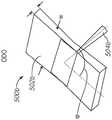
图5A到5B分别是OTLS显微镜在第一及第二操作模式下的照明及所收集的光的示意图。5A-5B are schematic diagrams of the illumination and collected light of an OTLS microscope in first and second modes of operation, respectively.
图6A到6B展示根据本公开的一些实施例的具有双照明模式的混合OTLS显微镜。6A-6B show a hybrid OTLS microscope with dual illumination modes according to some embodiments of the present disclosure.
图7是根据本公开的一些实施例的用显微镜照明样品的方法的框图。7 is a block diagram of a method of illuminating a sample with a microscope in accordance with some embodiments of the present disclosure.
图8A到8D是根据本公开的一些实施例的不同重定向光学器件的示意图。图8A到8C是可用于重定向照明轴与收集轴之间的非正交角的重定向光学器件的示意图,而图8D是更详细地展示图8C的重定向光学器件800c的实例操作的示意图。8A-8D are schematic diagrams of different redirecting optics according to some embodiments of the present disclosure. 8A-8C are schematic diagrams of redirecting optics that can be used to redirect non-orthogonal angles between the illumination axis and the collection axis, while FIG. 8D is a schematic diagram showing example operation of the redirecting
具体实施方式Detailed ways
对某些实施例的以下描述本质上只是示范性的,并不旨在限制本公开的范围或其应用或用途。在对本系统及方法的实施例的以下详细描述中,参考构成本系统及方法的一部分的附图,且附图通过说明的方式展示其中可实践所描述的系统及方法的特定实施例。对这些实施例进行了足够详细的描述,以使所属领域的技术人员能够实践当前公开的系统及方法,且应理解,可使用其它实施例,且可在不脱离本公开的精神及范围的情况下进行结构及逻辑改变。此外,为了清楚起见,当某些特征的详细描述对所属领域的技术人员来说是显而易见的时,将不讨论这些特征的详细描述,以避免模糊本公开的实施例的描述。因此,以下详细描述不具有限制性,且本公开的范围仅由所附权利要求书限定。The following description of certain embodiments is merely exemplary in nature and is not intended to limit the scope of the present disclosure or its application or uses. In the following detailed description of embodiments of the present system and method, reference is made to the accompanying drawings which form a part hereof and which show, by way of illustration, specific embodiments in which the described systems and methods may be practiced. These embodiments are described in sufficient detail to enable those skilled in the art to practice the presently disclosed systems and methods, and it is to be understood that other embodiments may be used and that they may be used without departing from the spirit and scope of the present disclosure Make structural and logical changes below. Furthermore, for the purpose of clarity, detailed descriptions of certain features are not discussed when they are apparent to those skilled in the art to avoid obscuring the description of embodiments of the present disclosure. Therefore, the following detailed description is not intended to be limiting, and the scope of the present disclosure is limited only by the appended claims.
一种开顶式光片(OTLS)显微镜包含样品固持器,其在样品固持器的顶侧上支撑要成像的样品,而照明及收集光学器件定位在样品固持器的相对底侧下方。因此,光可从照明物镜穿过样品固持器进入样品的照明区域。来自照明区域的光可穿过样品固持器并到达收集物镜,收集物镜可将所收集的光成像到检测器(例如,CCD、CMOS等)上。利用两个单独的物镜可能是有利的,照明物镜用于将照明光片引导到样品上,且收集物镜用于从样品收集光并将其引导向检测器。An open-top light sheet (OTS) microscope includes a sample holder that supports a sample to be imaged on the top side of the sample holder, with illumination and collection optics positioned below the opposite bottom side of the sample holder. Thus, light can pass from the illumination objective through the sample holder into the illuminated area of the sample. Light from the illumination area can pass through the sample holder and reach the collection objective, which can image the collected light onto a detector (eg, CCD, CMOS, etc.). It may be advantageous to utilize two separate objectives, the illumination objective to direct the illumination light sheet onto the sample and the collection objective to collect light from the sample and direct it towards the detector.
一些OTLS显微镜可能在照明与收集物镜的光轴之间使用正交几何形状。例如,照明及收集轴每一者可相对于样本成45°并相对于彼此成90°。此类设计可能存在缺陷。例如,可实现的成像分辨率受到物镜(照明及/或收集)的NA的限制。更高的NA物镜可实现更高的分辨率,但其倾向于具有更短的工作距离,且因此对样本的成像深度也更短。如果物镜经定向与样品成倾斜角,此限制可能会加剧,因为两个物镜的工作距离经定向使得光必须传播更远的距离以到达成像区域。这可能会限制相对较厚样本的成像深度,且因此限制可以所期望的高分辨率成像的样本厚度。另一实例缺点是,针对具有高NA物镜的OTLS显微镜,离轴聚焦光束的质量(即,相对于样品不正交)可能会因清除的组织、样品固持器及浸没介质之间非常小的折射率差异而严重退化(畸变)。因此,此类系统可能会对浸没流体、样本固持器及组织的折射率匹配提出相对严格的要求。可能期望设计一个能够克服这些挑战中的一或多者的显微镜。Some OTLS microscopes may use orthogonal geometries between the optical axes of the illumination and collection objectives. For example, the illumination and collection axes may each be at 45° relative to the sample and 90° relative to each other. Such designs may have flaws. For example, the achievable imaging resolution is limited by the NA of the objective (illumination and/or collection). Higher NA objectives allow for higher resolution, but they tend to have shorter working distances and therefore shorter imaging depths of the sample. This limitation may be exacerbated if the objectives are oriented at an oblique angle to the sample, since the working distances of the two objectives are oriented such that the light must travel a greater distance to reach the imaging area. This may limit the imaging depth of relatively thick samples, and thus the thickness of the sample that can be imaged at the desired high resolution. Another example disadvantage is that, for OTLS microscopes with high NA objectives, the quality of the off-axis focused beam (i.e., not orthogonal with respect to the sample) can be affected by very little refraction between the cleared tissue, the sample holder, and the immersion medium. Severe degradation (distortion) due to rate differences. Therefore, such systems may place relatively stringent requirements on the refractive index matching of the immersion fluid, sample holder, and tissue. It may be desirable to design a microscope that can overcome one or more of these challenges.
本公开涉及一种具有照明及收集物镜的非正交布置的开顶式光片显微镜。换句话说,照明物镜可具有照明光轴,且收集物镜可具有收集光轴,且照明与收集光轴彼此不正交。在一些实施例中,收集物镜可大致正交于样品固持器的平面(例如,收集轴可法向于支撑样品的表面),而照明物镜是非正交的(例如,以45°角)。这可能允许OTLS显微镜,其中收集物镜能够使用其全部成像深度(工作距离)。这继而可能会使使用相对较高的NA收集物镜(其倾向于具有较短的工作距离)变得更容易,这可允许对样品进行高分辨率成像。这种几何结构的使用还可降低收集路径的指数匹配要求,因为所收集的光可能以低入射角穿过样品固持器。这种几何形状也可能是有利的,因为其不会对样品的移动施加横向约束。The present disclosure relates to an open-top light-sheet microscope with a non-orthogonal arrangement of illumination and collection objectives. In other words, the illumination objective may have an illumination optical axis, and the collection objective may have a collection optical axis, and the illumination and collection optical axes are not orthogonal to each other. In some embodiments, the collection objective may be approximately orthogonal to the plane of the sample holder (eg, the collection axis may be normal to the surface supporting the sample), while the illumination objective is non-orthogonal (eg, at a 45° angle). This may allow OTLS microscopy, where the collection objective can use its full imaging depth (working distance). This in turn may make it easier to use relatively high NA collection objectives (which tend to have shorter working distances), which may allow high resolution imaging of the sample. The use of this geometry can also reduce the index matching requirements of the collection path, since the collected light may pass through the sample holder at low angles of incidence. This geometry may also be advantageous because it does not impose lateral constraints on the movement of the sample.
在一些实施例中,OTLS显微镜可包含第二收集物镜,其可经定向正交于照明物镜(且不正交于样品固持器)。OTLS显微镜可包含允许在两个光学路径(例如,两个收集物镜)之间交换的光学器件。不正交于照明(且可正交于样品固持器的平面)的第一收集物镜可为比正交于照明物镜的第二收集物镜更高的NA。两个收集路径的使用可允许显微镜在高放大及低放大模式下操作,这可能是有用的,例如,用于用较低的NA物镜(且因此视野较大)筛选样品,以识别所关注的区域,然后用较高的NA物镜更详细地研究这些区域。可通过调整照明及/或收集光学器件调谐显微镜的分辨率。In some embodiments, the OTLS microscope can include a second collection objective, which can be oriented normal to the illumination objective (and not normal to the sample holder). OTLS microscopes may contain optics that allow switching between two optical paths (eg, two collection objectives). The first collection objective, which is not normal to the illumination (and may be normal to the plane of the sample holder), may have a higher NA than the second collection objective, which is normal to the illumination objective. The use of two collection paths may allow the microscope to operate in high and low magnification modes, which may be useful, for example, for screening samples with lower NA objectives (and thus larger fields of view) to identify objects of interest regions and then study these regions in more detail with higher NA objectives. The resolution of the microscope can be tuned by adjusting the illumination and/or collection optics.
图1是根据本公开的一些实施例的开顶式光片(OTLS)显微镜的框图。图1展示光学系统100,其包含开顶式光片(OTLS)显微镜102及任选的控制器104,控制器104可操作显微镜102及/或解释来自显微镜102的信息。在一些实施例中,可省略控制器104的一或多个部分,且可手动操作显微镜102。在一些实施例中,控制器104的一或多个部分可集成到显微镜102中。1 is a block diagram of an open-top light sheet (OTS) microscope according to some embodiments of the present disclosure. FIG. 1 shows an
显微镜102包含样品固持器108,其沿样品固持器108的顶侧支撑样品106。显微镜102具有彼此分离的照明路径及收集路径。照明路径包含光源118、照明光学器件120及照明物镜122。照明路径提供照明光束124,其穿过样品固持器108以照明样品106。收集路径包含收集物镜128、收集光学器件130及检测器132。收集路径可从由照明光束124照明的聚焦区域126收集光。收集物镜128的光轴可相对于照明物镜122的光轴成θ角(例如,与照明光束124成θ角)。角θ可为非正交的(例如,锐角)。照明及光学组件的此类布置通常可称为非正交双物镜(NODO)系统。The
照明物镜122及收集物镜128通常可位于样品固持器108的底侧下方。这可能会使样品固持器108的顶侧相对打开,这继而使样品106易于放置在样品固持器108上。例如,样品固持器可具有为平板的顶部表面(例如,类似于商用平板扫描仪),且不同的样品可放置在平板上。这还可减少/消除样品106上的横向约束。The
在一些实施例中,显微镜102可包含额外的任选第二收集物镜160。第二收集物镜160可使用相对于照明光束124的照明轴成


在一些实施例中,显微镜102可包含任选的浸没流体腔室110,浸没流体腔室110继而含有浸没流体112。浸没流体112可帮助将照明及/或所收集的光耦合到样品中。例如,浸没流体112用作与样品固持器108及/或样品106的折射率匹配流体,这可减少通过其的光的折射。在一些实施例中,照明物镜122及收集物镜128中的一或两者可为空气物镜,由环境介质(例如,空气)环绕。因此,光可在空气与浸没流体112之间通过。任选的光学元件(例如透镜或窗口)可帮助在空气/浸没流体界面之间耦合光。在一些实施例中,照明物镜122及收集物镜128中的一或两者可为浸没物镜,其中物镜的至少一部分(例如,前透镜)与浸没流体112接触。例如,照明物镜122可为空气物镜,且照明光束124可在到达样品126之前穿过空气,穿过透镜/窗口(未展示)进入浸没流体112。来自聚焦区域126的光可穿过浸没流体112由收集物镜128收集,而不会穿过空气。In some embodiments,
光源118沿照明路径提供照明光,以照明样品106的聚焦区域126。光源118可为窄带光源,例如可以窄光谱发射光的激光器或发光二极管(LED)。在一些实施例中,光可为宽带光源(例如,白炽光源、弧光光源),其可产生宽光谱(例如,白色)照明。在一些实施例中,照明光的一或多个部分可在可见范围之外。在一些实施例中,滤光器(未展示)可用作照明路径的一部分,以进一步细化照明光的波长。例如,带通滤光器可从光源118接收宽带照明,并提供更窄光谱的照明光。在一些实施例中,光源103可为激光器,且可产生准直光。
在一些实施例中,光学系统100可用于对样品106中的荧光进行成像。照明光束124可包含特定激发波长的光,其可激发样品106中的荧光。照明光束124可包含包括激发波长的宽光谱,或可为集中于激发波长的窄带。在一些实施例中,光源118可产生集中于激发波长(或接近激发波长)的窄光谱。在一些实施例中,可在照明光学器件120中使用滤光器(未展示),以将照明光束124限制在激发波长附近的波长。一旦被照明光束124激发,样品106中的荧光可发射光(其可集中于给定发射波长)。收集路径(例如,收集光学器件130)可包含一或多个滤光器,其可用于将到达检测器132的光限制为发射波长附近的光波长。In some embodiments,
照明光学器件120可将光从光源118耦合到照明物镜122。例如,照明光学器件120可包含将光从光源118载送到照明物镜122的后端的光纤。在一些实施例中,照明光学器件120可在光源118与物镜122之间耦合光,而不会实质性地改变由光源118提供的光。在一些实施例中,照明光学器件120可改变由光源118提供的光的形状、波长、强度及/或其它性质。例如,照明光学器件120可从光源118接收宽带光,且可过滤光(例如,使用滤光器、衍射光栅、声光调制器等)以将窄带光提供到物镜122。
在一些实施例中,照明光学器件120可包含扫描光学器件(例如,扫描镜),其可用于扫描照明光。在一些实施例中,扫描光学器件可用于以光片的形式产生照明光束124(例如,通过在一个轴上来回扫描光,而不是在另一轴上)。在一些实施例中,扫描光学器件可用于改变视野相对于样品106的位置。In some embodiments,
在一些实施例中,照明光学器件120可为可调整的。例如,如果显微镜102支持多于一个成像模式(例如,共享同一照明物镜的多个收集物镜),那么照明光学器件120可包含一或多个组件,这些组件可取决于成像模式进行调整或调谐。图3中更详细地讨论使用多个成像模式的实例显微镜,且图5中更详细地讨论调谐照明光学器件120的实例。In some embodiments, the
照明路径可提供照明光束124,照明光束124是作为光片显微镜或光片荧光显微镜(LSFM)的一部分的光片。光片可具有通常椭圆形的横截面,具有沿第一轴(例如,y轴)的第一数值孔径及沿正交于第一轴的第二轴的大于第一数值孔径的第二数值孔径。照明光学器件120可包含将从光源118接收的光重成形为照明片的光学器件。例如,照明光学器件120可包含一或多个圆柱形光学器件,其将光聚焦在一个轴上,但不聚焦在正交轴上。The illumination path may provide an illumination beam 124, which is a light sheet that is part of a light sheet microscope or light sheet fluorescence microscope (LSFM). The light sheet may have a generally elliptical cross-section with a first numerical aperture along a first axis (eg, the y-axis) and a second numerical aperture greater than the first numerical aperture along a second axis orthogonal to the first axis .
在一些实施例中,照明光学器件120可包含扫描光学器件,其可用于相对于样品106扫描照明光束124。例如,由照明光束照明的区域可小于所期望的聚焦区域126。在这种情况下,照明光学器件120可使照明光束124在所期望的聚焦区域126上快速振荡,以确保聚焦区域126的照明。In some embodiments,
照明物镜122可包含一或多个透镜,其提供照明光束124。例如,照明物镜122可使照明光束124朝向聚焦区域126聚焦。样品固持器108可定位样品106,使得聚焦区域126通常位于样品106内。在一些实施例中,样品固持器108可包含一或多个致动器,其可相对于聚焦区域126定位样品106。在一些实施例中,照明物镜可为包含一或多个内部光学元件的商用物镜。在一些实施例中,照明物镜122可被周围环境(例如,空气)环绕,且照明物镜122可为空气物镜。照明物镜122可由一或多个数值孔径表征,其可基于光在聚焦区域126处会聚的角。在一些实施例中,照明物镜122可为浸没物镜,且照明物镜122的至少一部分可与浸没流体112接触。
在一些实施例中,聚焦区域126可理想化为聚焦平面。照明光束124可被引导到样品106上以产生聚焦区域126。聚焦区域126可理想化为由照明光片124照明的平坦(例如,2D)平面。聚焦平面可与照明光片124对准,且可表示由照明光束124成像的区域,收集物镜128可从其收集光。在一些实施例中,聚焦区域126可表示收集物镜128的单个视野。在一些实施例中,聚焦区域126可表示可扫描收集物镜128的视野的区域。In some embodiments,
样品106可由样品固持器108的上表面支撑。在一些实施例中,样品106可直接放置在样品固持器108的上表面上。在一些实施例中,样品106可封装在容器中(例如,在玻璃载玻片上、在孔板中、在组织培养瓶中等),且容器可放置在样品固持器108上。在一些实施例中,容器可集成到样品固持器108中。在一些实施例中,可在光学系统100上成像之前处理样品106。例如,可在成像之前清洗、切片及/或标记样品106。The
在一些实施例中,样品106可为生物样品。例如,样品106可为从疑似疾病(例如,癌症)区域进行活检的组织。在一些实施例中,组织在被光学系统100检查之前可经历各种处理,例如光学清除、组织切片及/或标记。在一些实施例中,使用光学系统100对组织的检查可用于诊断、确定治疗进展、监测疾病进展等。In some embodiments, the
在一些实施例中,样品106可为非生物的。例如,样品106可为流体,且可含有一或多个用于研究的组分。例如,样品106可为燃烧气体,且光学系统106可执行粒子图像测速(PIV)测量来表征气体的组分。In some embodiments, the
在一些实施例中,样品106可包含一或多个类型的荧光。荧光可为样品106固有的(例如,生物样品中的DNA及蛋白质),或可为应用于样品106的荧光标签(例如,吖啶橙、曙红)。一些样品106可包含荧光的固有类型及荧光标签的混合物。每一类型的荧光可具有激发光谱,其可集中于激发波长上。当荧光被激发光谱中的光激发时,其可在发射光谱中发射光,发射光谱可能集中于不同于激发波长(例如,相对于激发波长红移)的发射波长上。In some embodiments,
样品固持器108可将样品106支撑在对照明光束124及从样品106的聚焦区域126收集的光通常透明的材料上。在一些实施例中,样品固持器108可具有透明材料的窗口,样品106可放置在其上,且样品固持器108的剩余部分可由不透明材料形成。在一些实施例中,样品固持器108可由透明材料制成。例如,样品固持器108可包含支撑样品106的玻璃板。The
在一些实施例中,样品固持器108可包含支撑样品106的一或多个结构。例如,样品固持器108可包含夹子或孔。在一些实施例中,样品固持器108可为系统100的模块化组件,且不同的样品固持器108可取决于样品类型、成像类型、照明/所收集的光的波长及其组合进行交换。In some embodiments, the
样品固持器108可具有第二表面(例如,下表面),其与支撑样品106的样品固持器108的表面相对。在一些实施例中,固持浸没流体112的浸没腔室110可定位在样品固持器108的第二表面下方。在一些实施例中,浸没腔室110可具有开口顶部,且浸没流体112可与样品固持器108的第二表面接触。在一些实施例中,虽然样品固持器108的第二表面可与浸没流体112接触,但样品固持器108的第一表面(其支撑样品106)可与和物镜122及128相同的环境(例如,空气)接触。The
样品固持器108可耦合到致动器109,致动器109能够在一或多个方向上移动样品固持器108。在一些实施例中,样品固持器108可相对于浸没腔室110以及物镜122及128在一或多个维度上移动。例如,样品固持器108可沿x轴、y轴及/或z轴移动,及/或可旋转(例如倾倒、倾斜等)。可移动样品固持器108以改变样品106内聚焦区域126的位置及/或在加载位置与成像位置之间移动样品固持器108。在一些实施例中,致动器可为手动致动器,例如螺钉或粗/精调整旋钮。在一些实施例中,致动器可为自动化的,例如电动机,其可对手动输入及/或来自控制器104的指令作出响应。在一些实施例中,致动器109可对手动调整及自动控制两者作出响应(例如,对手动转动及来自控制器104的指令作出响应的旋钮)。The
任选的浸没腔室110含有浸没流体112。在一些实施例中,浸没腔室110可包含源及/或水槽,其可用于更换浸没流体112。例如,浸没腔室110可耦合到流体输入管线(其继而可耦合到泵及/或储存器),其提供浸没流体112及排水管,排水管可打开以从浸没腔室110移除浸没流体112。如本文更详细地描述的,可基于样品106及/或样品固持器108的折射率来选择浸没流体的类型。The
收集路径可从聚焦区域126接收光,并将所接收的光引导到检测器132上,检测器132可成像及/或以其它方式测量所接收的光。来自聚焦区域126的光可为照明光束124的重引导部分(例如,散射光及/或反射光),可为响应于照明光束124(例如,通过荧光)从聚焦区域126发射的光,或其组合。所收集的光可穿过样品固持器108,朝向收集物镜128。The collection path may receive light from the
在图1的NODO几何结构中,收集路径可具有以相对于样品固持器108的平面(例如图1的XY-平面)的角γ布置的主光轴。在一些实施例中,例如图1中所说明的一个实施例,角γ可约为90°,即,收集路径可具有近似正交于样品固持器108的平面的主光轴。如果由收集物镜收集的图像质量仍受到衍射限制,即使用斯特列尔比作为优值,其中斯特列尔比大于约0.8,那么角γ可足够接近90°,即可近似正交。对于所属领域的技术人员来说,显而易见的是,斯特列尔比可能取决于许多可能适用于给定OTLS显微镜系统的参数,例如折射率失配(即光学路径差,或固持器与浸没介质/清除组织样品之间的折射率差与固持器厚度的乘积),照明及收集物镜的NA、物镜的视野、照明光及/或所收集的光的波长,及使用的特定物镜,以及角α。In the NODO geometry of FIG. 1 , the collection path may have a principal optical axis arranged at an angle γ relative to the plane of the sample holder 108 (eg, the XY-plane of FIG. 1 ). In some embodiments, such as the one illustrated in FIG. 1 , the angle γ may be approximately 90°, ie, the collection path may have a principal optical axis approximately normal to the plane of the
照明路径可具有以相对于收集路径的主光轴的角θ布置的主光轴,且角θ可为非正交的,即可为锐角。若干因素可限制角θ的可接受值的范围。例如,角等于或接近90°,即接近平行于样本固持器的平面,可能是不切实际的,因为其会与样本固持器相交,并约束样本的横向尺寸。指数匹配约束也可能变得过于繁重,即使对于照明光束的相对较低NA也是如此。其它因素可能会限制角θ的值的范围的下限,包含由收集物镜的机械外壳施加的物理约束。图2中更详细地讨论物镜的几何结构施加的实例限制。The illumination path may have a main optical axis arranged at an angle Θ relative to the main optical axis of the collection path, and the angle Θ may be non-orthogonal, ie an acute angle. Several factors can limit the range of acceptable values for angle Θ. For example, an angle equal to or close to 90°, ie nearly parallel to the plane of the sample holder, may be impractical because it would intersect the sample holder and constrain the lateral dimensions of the sample. Exponential matching constraints can also become too onerous, even for the relatively low NA of the illumination beam. Other factors may limit the lower limit of the range of values for angle Θ, including physical constraints imposed by the mechanical housing of the collection objective. Example constraints imposed by the geometry of the objective are discussed in more detail in FIG. 2 .
聚焦区域126的几何结构可部分地由收集路径的视野界定,其继而可部分地取决于收集物镜128的数值孔径。类似于照明物镜122,收集物镜128可为包含一或多个透镜的商业物镜。在一些实施例中,收集物镜128可为空气物镜。在一些实施例中,收集物镜128可为浸没物镜(例如,油浸物镜)。在一些实施例中,收集物镜128可使用与照明路径中使用的浸没流体112不同的浸没介质。在一些实施例中,收集路径聚焦的聚焦区域及照明路径聚焦的聚焦区域通常可在聚焦区域126处重叠。在一些实施例中,照明及收集路径可具有其相应聚焦区域的不同形状、大小及/或位置。The geometry of the
收集路径包含收集光学器件130,其可将光从收集物镜重引导到检测器132上。例如,收集光学器件130可为管透镜,其经设计以将来自收集物镜后端的光聚焦到投影到检测器132上的图像中。在一些实施例中,收集光学器件130可包含一或多个元件,其改变从收集物镜128接收的光。例如,收集光学器件130可包含滤光器、反射镜、解扫描光学器件或其组合。The collection path includes
收集光学器件130可包含可重定向聚焦区域126的视图的光学器件。由于收集物镜128的轴相对于聚焦区域126成θ角,因此图像可能会失真。收集光学器件130可包含一或多个特征,其可重定向图像以考虑图像投影到检测器132上之前的角θ。例如,收集光学器件130可包含远程聚焦,其中第一透镜投影由收集物镜128收集的光的图像,且第二透镜以抵消角θ的角对所述远程图像进行成像。这可校正由于光到达检测器132之前的角θ引起的失真。在其它实例实施例中,可使用重定向图像的其它方法。
检测器132可用于对聚焦区域126进行成像。在一些实施例中,检测器132可表示目镜,使得用户可观察聚焦区域126。在一些实施例中,检测器132可产生用于记录聚焦区域126的图像的信号。例如,检测器132可包含CCD或CMOS阵列,其可基于入射到阵列上的光产生电子信号。
显微镜102可耦合到控制器104,控制器104可用于操作显微镜102的一或多个部分、显示来自显微镜102的数据、解释来自显微镜102的数据或其组合。在一些实施例中,控制器104可与显微镜分离,例如通用计算机。在一些实施例中,控制器104的一或多个部分可与显微镜102集成。
控制器104包含一或多个输入/输出装置142,其可允许用户查看来自控制器104的反馈、来自显微镜102的数据、将指令提供到控制器104、将指令提供到显微镜102或其组合。例如,输入/输出装置142可包含数字显示器、触摸屏、鼠标、键盘或其组合。
控制器104包含处理器140,其可执行存储在存储器144中的一或多个指令。指令可包含控制软件152,其可包含关于如何控制显微镜102的指令。基于控制软件152,处理器140可使控制器104向显微镜102的各种组件(例如致动器109)发送信号。指令可包含图像处理软件150,其可用于处理来自检测器132的“实时”或先前存储在存储器144中的图像146。例如,图像处理软件150可从图像146移除背景噪声。指令可包含分析软件148,其可由处理器140执行以确定图像146的一或多个性质。例如,分析软件148可高亮显示图像146中的细胞核。
在一些实施例中,控制器104可引导显微镜从样品中的多个不同视野收集图像。例如,控制器104可包含用于收集图像深度堆叠的指令。控制器104可引导检测器132收集第一图像,然后指示致动器109在垂直方向(例如,沿z轴)将样品固持器108移动设定距离。这还可相对于聚焦区域126移动样品106,这可改变聚焦区域126所在的样品内的高度。然后,控制器104可指示检测器132收集另一图像,然后重复过程,直到在堆叠中获得设定数量的图像及/或在z方向上获得设定的总位移。然后,分析软件148可组合图像的深度堆叠,以允许对样品106进行三维(或伪三维)成像。以类似的方式,可使用各种其它平移来收集多个视野。例如,可在x、y及/或z轴上扫描样品。OTLS的几何形状对于X或Y方向上的扫描可能尤其有用,因为样品固持器108下的物镜(及其它光学器件)的位置可能允许在这些方向上进行较少约束的扫描。In some embodiments, the
在一些实施例中,控制器104可帮助在一或多个操作(或成像)模式之间切换显微镜102。例如,控制器104可致动各种组件,或激活/去激活一或多个组件。例如,在第一成像模式下,可从收集物镜128收集光,而在第二成像模式下,可通过不同的收集物镜收集光(图1中未展示)。图3到6B中更详细地讨论具有多个成像模式的实例实施例。In some embodiments,
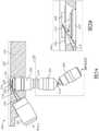
图2A到2D是根据本公开的一些实施例的OTLS显微镜的一部分的示意图。图2A展示OTLS显微镜的布局,且图2B到2D展示图2A的显微镜的一部分的详细视图。在一些实施例中,OTLS显微镜200可包含在图1的显微镜102中。为了简洁起见,已相对于图1描述的细节及操作将不再相对于图2重复。2A-2D are schematic diagrams of a portion of an OTLS microscope according to some embodiments of the present disclosure. Figure 2A shows the layout of an OTLS microscope, and Figures 2B-2D show detailed views of a portion of the microscope of Figure 2A. In some embodiments,
图2展示显微镜的示意图,其聚焦于照明及收集光学器件与浸没腔室及样品以及收集光学器件的一部分的相互作用。显微镜200可包含额外组件,为了图中的清晰起见,图2中省略这些组件。Figure 2 shows a schematic diagram of a microscope focusing on the interaction of illumination and collection optics with an immersion chamber and a portion of the sample and collection optics.
显微镜200包含照明物镜202,其从照明源及任选的其它照明光学器件(未展示)接收照明光,并将照明光束218通过透镜218引导到浸没流体222中。浸没流体222由浸入腔室220容纳。浸没光218穿过样品固持器226的底部表面进入样品228。所收集的光216从样品228射出,穿过样品固持器226及浸没流体222进入收集物镜204。照明光218的主轴可不正交于样品固持器226的平面,而所收集的光216的主轴可近似正交于样品固持器226的平面。因此,照明光218及所收集的光216可彼此不正交。
显微镜200展示实例重定向光学器件230,其可用于调节照明光218与所收集的光216之间的非正交角θ。可使用各种类型的重定向光学器件230。图2的实例展示使用远程图像212的重定向光学器件230的特定实施方案。然而,其它实施例可使用其它方案实现重定向光学器件230。图8A到8D中讨论可用于代替图2的重定向光学器件230的各种实例重定向光学器件。
在图2的重定向光学器件230中,收集物镜204可将光通过任选的转移光学器件210引导到第二收集物镜206中。第二收集物镜206可产生远程图像212,远程图像212可由第三收集物镜208进行成像。第二收集物镜206及第三收集物镜208可成一定角。此角可基于所收集的光216与照明光218之间的角。第三收集物镜208可将光引导到检测系统(未展示)。In the
照明物镜202可为空气物镜,其中近端透镜(例如,发射照明光束218的透镜)定位在空气中。在一些实施例中,照明物镜202可完全定位在空气中。然而,样品固持器226的至少一部分可定位在与浸没流体222接触的位置。透镜224可将照明光218从环绕照明物镜202的空气耦合到浸没流体222中。
在一些实施例中,透镜224可经成形以减少光从空气通过透镜224的材料并进入浸没流体222时的折射。在一些实施例中,透镜224可由具有与浸没流体222的折射率匹配的折射率的材料制成。在一些实施例中,透镜224可具有经成形以与通过其的光的波前匹配的一或多个表面,这可消除/减少通过透镜224的光的折射。例如,透镜224可为固体浸没(SIL)透镜或固体浸没弯月面透镜(SIMlens),如第10,409,052号美国专利及第WO 2020/150239号PCT公开案中所公开,其公开内容以引用的方式并入本文中。In some embodiments, the
在通过透镜224之后,照明光束218可通过浸没流体222,直到其遇到样品固持器226。浸没流体222可具有与样品固持器226的折射率匹配的折射率。这可帮助最小化/防止照明光束218从浸没流体222进入样品固持器216的材料时的折射。继而,样品固持器216的折射率可经选择使得其与样品228(及浸没流体222)的折射率匹配。这可最小化/防止照明光束218从样品固持器进入样品228时的折射。After passing through
在一些实施例中,样品228及样品固持器226可浸入浸没流体222中。在一些实施例中,样品固持器226的底部表面可与浸没流体222接触,但支撑样品228的顶部表面可与空气接触。例如,样品固持器226可用作浸没腔室220的盖。In some embodiments, the
所收集的光216可在进入收集物镜204的近端透镜之前离开样品228并通过样品固持器226及浸没流体222。收集物镜可为浸没物镜,其中近端透镜与浸没流体222接触。收集物镜204的远端可定位在周围环境(例如,空气中)中的浸没流体222的外部。收集的光216可表示离开样品228的光的一部分,这部分光通过收集物镜204及其它收集光学器件到达检测器。所收集的光216的大小及几何结构可至少部分地基于收集物镜204及其它收集光学器件。
收集物镜204的近端透镜可位于比照明物镜202的近端透镜更靠近样品228的位置。这可允许收集物镜204是NA比照明物镜202更高的物镜。由于收集物镜204近似正交于样品固持器226的平面,因此可减小折射(与照明光束218相比)。在一些实施例中,收集物镜204可为空气物镜,且可通过窗口将其与浸没流体222分离,而不是浸入浸没流体222中。The proximal lens of
收集物镜204的后端可通过任选的转移光学器件210将光引导到第二收集物镜206。在一些实施例中,转移光学器件210可包含一或多个透镜。例如,转移光学器件210可为4f中继系统。The rear end of the
图2的显微镜200包含用于重定向由收集物镜204收集的图像的任选特征。例如,第二收集物镜206可投影远程图像212。远程图像212可用于校正样品222中的照明平面(例如,照明光束218)与所收集的光216之间的角。远程图像212可由第三收集物镜208进行成像。为了校正照明光束218与所收集的光216之间的角,第三收集物镜208可以相对于第二收集物镜206的角对远程图像212进行成像。角可基于照明与所收集的光之间的角。例如,如果照明光束218与所收集的光216之间的角为θ,那么第二物镜206与第三物镜208之间的角可为90°-θ。例如,如果角θ约为45°,那么第二收集物镜206与第三收集物镜208之间的角也可能约为45°。The
例如,如图2B中所展示,收集物镜的实例机械外壳允许在两侧上以45°照明光学路径,具有β的最大锥角(例如,照明光218的光轴与收集物镜204的边缘之间的角)。在一些实施例中,角β可约为7.1°(例如,照明光在空气中可具有约为0.12的NA)。最大锥角可基于物镜204的机械外壳的大小/形状而变化,且在其它实例实施例中可使用其它角。For example, as shown in FIG. 2B , an example mechanical housing of the collection objective allows the illumination optical path at 45° on both sides, with a maximum cone angle of β (eg, between the optical axis of the
针对具有相对较高NA的单个收集物镜的OTLS系统,角θ可能大于45°,如图2C中所展示。在一些实施例中,可能期望具有两个照明物镜,用于双侧照明,并使用相同的相对较高的NA单个收集物镜,如图2D中所展示。图2D展示具有第二照明物镜240的实施例。照明物镜202及240中的每一者可以相对于收集物镜204的轴的非正交角定位。在图2D的实施例中,两者都以大于45°的角定位。在其它实例实施例中,可使用其它角(例如,小于或等于45°的角)。For OTLS systems with a single collection objective with relatively high NA, the angle θ may be greater than 45°, as demonstrated in Figure 2C. In some embodiments, it may be desirable to have two illumination objectives for bilateral illumination and use the same relatively high NA single collection objective, as shown in Figure 2D. FIG. 2D shows an embodiment with a
具有更大、更浅角外壳的收集物镜可进一步限制照明光学路径角的范围。从另一角来看,照明光片可倾斜到一定程度(即不同于正交),使其不在所期望的视野的收集物镜的共焦参数(聚焦深度)内。考虑到这些因素,θ角的合理范围可能为40°到70°。例如,照明路径可跟随第一光轴,其相对于样品固持器的底部表面成45°角,而收集路径可跟随第二光轴,其相对于样品固持器108的平面成90°角。因此,第一与第二光轴之间可能存在约45°角,即,角θ可能约为45°。Collection objectives with larger, shallower housings can further limit the range of illumination optical path angles. Viewed from another angle, the illumination light sheet can be tilted to a degree (ie, other than orthogonal) that it is not within the confocal parameters (depth of focus) of the collection objective for the desired field of view. Taking these factors into consideration, a reasonable range for the theta angle might be 40° to 70°. For example, the illumination path may follow a first optical axis at a 45° angle relative to the bottom surface of the sample holder, while the collection path may follow a second optical axis at a 90° angle relative to the plane of the
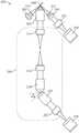
图3A到3C是根据本公开的一些实施例的OTLS显微镜的示意图。图3A展示显微镜3A,且图3B及3C展示照明及收集物镜的不同布置的展开视图,其可与图3A的显微镜一起使用。在一些实施例中,显微镜300可包含在图1的显微镜102及/或图2的显微镜200中。显微镜300通常可类似于先前所描述的显微镜,不同之处在于除了图1到2中所描述的非正交成像路径之外,显微镜300还包含使用正交于照明片的收集物镜的额外成像路径。3A-3C are schematic diagrams of an OTLS microscope according to some embodiments of the present disclosure. Figure 3A shows microscope 3A, and Figures 3B and 3C show expanded views of different arrangements of illumination and collection objectives that can be used with the microscope of Figure 3A. In some embodiments,
由于显微镜300的非正交双物镜(NODO)路径通常可类似于图1的显微镜102及图2的显微镜200的操作及组件,因此为了简洁起见,相对于图1及2描述的特征及组件将不再相对于图3重复。Because the non-orthogonal dual objective (NODO) path of
显微镜300包含NODO光学路径及正交双物镜(ODO)光学路径。NODO路径及ODO路径可能共享某些组件,例如照明路径。显微镜300包含照明物镜302,其将照明光片通过透镜310(例如,SIL或SIMlens)引导到浸没流体(未展示)中,朝向样品308。第一收集物镜304可以非正交于照明光片的角从样品308收集光。第一收集物镜304可使光通过可形成中继器的第一透镜314及第二透镜316。中继器可将光传递到第二收集物镜318,第二收集物镜318可产生由第三收集物镜320以α角进行成像的远程图像。角α可为物镜304及318的光轴与物镜320的光轴之间的角。如图3中所展示,这也可能是法向于这些轴的平面之间的角。第三收集物镜320可将光通过第三透镜322,第三透镜322将光成像到第一检测器324上。
从光源(未展示)通过照明物镜302到样品308,及从样品308通过第一收集物镜304到第一检测器324的路径可形成NODO光路径。照明光路径及所收集的光(例如,照明物镜302及第一收集物镜304的光轴)可彼此处于非正交角θ。显微镜300包含重定向光学器件340(例如,类似于图2的重定向光学器件230)。虽然图3中展示重定向光学器件340的特定实施方案,但在其它实例实施例中可使用用于重定向的其它系统。图8A到8D包含一些可用作重定向光学器件340的额外实例重定向光学器件。A NODO light path may be formed from a light source (not shown) through the
显微镜300还包含第四收集物镜306,其具有近似正交于照明光片的光轴(例如,照明物镜302的光轴)。类似于照明物镜302,第四收集物镜306可为空气浸没物镜,且第四收集物镜306可通过第二透镜310(例如SIL或SIMlens)与浸没流体(未展示)分离。第四收集物镜306可从样品308收集光,并将所收集的光通过一或多个ODO收集光学器件引导到第二检测器328。例如,ODO收集光学器件可包含透镜326,其将来自第四收集物镜的光成像到第二检测器328上。
从光源(未展示)通过照明物镜302到样品308,及从样品308通过第四收集物镜306到第二检测器328的路径可形成ODO光路径。照明光路径及由第四收集物镜306收集的光(例如,照明物镜302的光轴及第四收集物镜306的光轴)可彼此正交。The path from the light source (not shown) through the
在一些实施例中,NODO及ODO光学路径可共享检测器,而非具有单独的第一检测器324及第二检测器328。显微镜300可包含额外光学器件(例如,旋转镜、快门等),其可切换来自NODO路径或ODO路径的光是否到达检测器。In some embodiments, the NODO and ODO optical paths may share detectors instead of having separate
在一些实施例中,照明路径可为可调整的,且可在ODO成像模式与NODO成像模式之间进行调整。例如,照明光学器件(未展示),例如图1的照明光学器件120,可包含可调整组件,其可基于使用第一收集物镜304或第四收集物镜306调谐照明光片的大小及形状。例如,照明光学器件可包含可变光束扩展器,其可用于调整照明光片的性质,例如光片的NA及/或宽度。照明光片的调整可为手动、自动(例如,由控制器管理)或其组合。照明路径的调整在图5中更详细地描述。In some embodiments, the illumination path may be adjustable, and may be adjusted between ODO and NODO imaging modes. For example, illumination optics (not shown), such as
在实例操作中,可将样品放置在显微镜上,且可使用ODO光学路径对样品进行筛选。ODO路径可具有较低的分辨率及放大率,但具有比NODO路径大的视野。因此,使用ODO路径筛选样品可能更有效。在一些实施例中,可扫描样品308(例如,通过聚焦区域相对于样品的运动,通过样品相对于聚焦区域的运动,或其组合)。在一些实施例中,多个视野可缝合在一起(例如,通过控制器,例如图1的104)。在一些实施例中,可在3维中扫描样品308以构建样品的体积图像。在一些实施例中,可手动执行扫描。In an example operation, a sample can be placed on a microscope and the sample can be screened using the ODO optical pathway. The ODO path may have lower resolution and magnification, but has a larger field of view than the NODO path. Therefore, it may be more efficient to use the ODO pathway to screen samples. In some embodiments, the
在扫描样品(或样品的一部分)之后,可识别所关注的区域。在一些实施例中,自动化过程(例如,图像处理,例如分割、定限等、机器学习及/或深度学习)可识别所关注的区域。在一些实施例中,用户(例如,临床医生)可确定所关注的区域。一旦定位一或多个所关注的区域,NODO路径就可用于所关注的区域的高分辨率成像。在一些实施例中,一旦识别出所关注的区域,显微镜300就可切换到NODO模式。切换到NODO模式可能涉及切换用于成像的检测器(或耦合到检测器的光学路径)。切换模式还可包含调整照明光片。After scanning the sample (or a portion of the sample), areas of interest can be identified. In some embodiments, automated processes (eg, image processing such as segmentation, delimitation, etc., machine learning and/or deep learning) may identify regions of interest. In some embodiments, a user (eg, a clinician) may determine the area of interest. Once one or more regions of interest are located, the NODO pathway can be used for high resolution imaging of the region of interest. In some embodiments, the
在NODO模式下,显微镜300可具有更高的分辨率及放大率,但具有更小的视野。NODO模式可用于确定所关注的区域的一或多个性质。例如,临床医生可确定所关注的区域,然后切换到NODO模式以进行诊断。在一些实施例中,NODO及/或ODO模式中的分辨率及/或视野可调整。这可能给显微镜300一个相对较大的不同性能特性的操作范围。In NODO mode,
在一些实施例中,在第一操作(成像)模式(例如,NODO模式)下收集的信息可与在第二操作(成像)模式(例如,ODO模式)下收集的信息相结合。此过程可为自动的。例如,控制器(例如,图1的104)可在ODO模式下对区域进行成像,然后使用图像处理(例如,分割、定限等)、机器学习、深度学习或其组合来确定经成像区域的全部或部分是否为所关注的区域。然后,控制器可使用NODO模式对所关注的区域进行更详细的成像。在一些实施例中,过程可为手动的,且用户可识别所关注的区域。在一些实施例中,可使用手动及自动过程的混合(例如,自动图像处理,但手动感兴趣区域识别)。In some embodiments, information collected in a first operational (imaging) mode (eg, NODO mode) may be combined with information collected in a second operational (imaging) mode (eg, ODO mode). This process can be automatic. For example, a controller (eg, 104 of FIG. 1 ) may image a region in ODO mode and then use image processing (eg, segmentation, delimitation, etc.), machine learning, deep learning, or a combination thereof to determine the size of the imaged region Whether in whole or in part the area of interest. The controller can then use NODO mode to image the area of interest in more detail. In some embodiments, the process may be manual and the user may identify the area of interest. In some embodiments, a mixture of manual and automatic processes may be used (eg, automatic image processing, but manual region of interest identification).
针对具有第二收集物镜的OTLS系统,例如图3A中所展示的,照明与第一收集物镜之间的角θ可经优化为45°,如图3B中所展示,且照明物镜与次级收集物镜的光学路径之间的角可约为90°。针对其中期望具有相对较高NA照明物镜的OTLS系统,可能期望照明物镜与次级物镜的光学路径之间的角大于90°,如图3C中所展示。For an OTLS system with a second collection objective, such as that shown in Figure 3A, the angle Θ between the illumination and the first collection objective may be optimized to 45°, as shown in Figure 3B, and the illumination objective and the secondary collection objective The angle between the optical paths of the objective lenses may be approximately 90°. For OTLS systems where a relatively high NA illumination objective is desired, it may be desirable to have an angle between the optical path of the illumination objective and the secondary objective greater than 90°, as shown in Figure 3C.
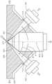
图4是根据本公开的一些实施例的显微镜的样品固持器。在一些实施例中,图4的样品固持器400可包含在显微镜中,例如图3的显微镜300,其使用NODO及ODO光学路径。图4展示聚焦于物镜与样品固持器400相互作用的视图,因此可省略显微镜的各种组件。为简洁起见,先前相对于图1到3讨论的操作、特征及组件将不再相对于图4重复。4 is a sample holder of a microscope according to some embodiments of the present disclosure. In some embodiments, the
样品固持器400支撑浸没流体420。包含样品固持器400的显微镜包含NODO光学路径及ODO光学路径。照明物镜402沿照明光轴403将照明光片提供到聚焦区域410。照明物镜402可为空气物镜,其未浸入浸没流体420中。因此,透镜412(例如SIL或SIMlens)可将照明光片耦合到浸没流体420中。
NODO收集物镜404可沿NODO收集轴405从聚焦区域410接收光。照明轴403与NODO收集轴405之间可能存在角θ。角θ可为非正交的,且在一些实施例中可为锐角,例如45°角。NODO收集物镜404可为浸没物镜,且NODO收集物镜404的至少一部分可与浸没流体420接触。
ODO收集物镜406可沿ODO光轴407从聚焦区域410接收光。照明轴403与ODO收集轴407之间可能存在角

从图4的视图中可看出,且如上文所讨论的,物镜402、404及406可经定位使得NODO收集物镜404不会阻挡来自照明物镜402或ODO收集物镜406的光。来自照明物镜402并由ODO收集物镜406收集的光的角可部分地基于这些物镜相应的NA。因此,这些物镜的NA以及NODO物镜404的大小及形状可经设计以不相互干扰。As can be seen from the view of FIG. 4 , and as discussed above,
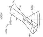
图5A到5B分别是OTLS显微镜在第一及第二操作模式下的照明及所收集的光的示意图。图5A及5B表示在NODO模式(图5A)及ODO模式(图5B)下,照明光片与由物镜收集的光之间的相互作用视图。图5A到5B的两个视图可表示由相同物理显微镜提供的光,但在不同的操作模式下。例如,图5A到5B的视图可表示混合OTLS显微镜的操作,例如图3到4中的一者所描述的。光学模式500a表示NODO模式,而光学模式500b表示ODO模式。5A-5B are schematic diagrams of the illumination and collected light of an OTLS microscope in first and second modes of operation, respectively. Figures 5A and 5B represent views of the interaction between the illumination light sheet and the light collected by the objective lens in NODO mode (Figure 5A) and ODO mode (Figure 5B). The two views of Figures 5A-5B may represent light provided by the same physical microscope, but in different modes of operation. For example, the views of FIGS. 5A-5B may represent the operation of a hybrid OTLS microscope, such as described in one of FIGS. 3-4.
图5A到5B中的每一者展示相应的照明光片502a/502b及相应的所收集的光锥504a/504b。照明光片及所收集的光相互作用以产生视野(FOV)。可在操作模式之间调整照明光片,以适应所收集的光的不同几何形状。Each of Figures 5A-5B shows a corresponding
图5A展示照明光片502a及所收集的光锥504a。照明光片502a可与所收集的光504a具有角θ。角θ可为非正交角,例如锐角,如上文参考图1到4所讨论。图5B展示照明光片502b及所收集的光锥504b。照明光片502b可与所收集的光504b具有角

所收集的光504a可为比所收集的光504b更宽的锥体,因为在NODO模式下,收集物镜可为比在ODO模式下使用的收集物镜的NA更高的NA。与照明光片502b相比,照明光片502a可具有增加的NA及更小的宽度W。因此,光学模式500a中的FOV小于光学模式500b中的FOV。这可能是由于照明光学器件中的调整。例如,可使用可调整光束扩展在模式之间改变照明光片的W及NA。The collected light 504a may be a wider cone than the collected light 504b because in NODO mode the collection objective may be of a higher NA than that of the collection objective used in ODO mode. The
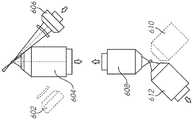
图6A到6B展示根据本公开的一些实施例的具有双照明模式的混合OTLS显微镜。图6A到6B中所展示的视图表示具有ODO模式及NODO模式两者的混合OTLS显微镜的部分。例如,在一些实施例中,图6A到6B的视图可表示图3的显微镜300的部分。为简洁起见,先前相对于一或多个先前附图描述的特征、组件及操作将不再相对于图6A-6B重复。6A-6B show a hybrid OTLS microscope with dual illumination modes according to some embodiments of the present disclosure. The views shown in Figures 6A-6B represent portions of a hybrid OTLS microscope with both ODO and NODO modes. For example, in some embodiments, the views of FIGS. 6A-6B may represent portions of
图6A到6B展示额外的成像模式,其可用于利用三个物镜(例如照明物镜、NODO收集物镜及ODO收集物镜),这三个物镜可引导来自样品的光及从样品接收光。系统也可经配置为通过ODO收集物镜提供照明的模式,而不是通过单个照明物镜为NODO路径提供照明。图6A展示在第一模式下操作的显微镜,其中照明光由第一物镜602提供,并由收集物镜604以非正交角接收。图6B展示在第二模式下操作的同一显微镜,其中照明光由第二物镜606提供,并由收集物镜604以非正交角接收。在一些实施例中,可组合使用两种模式获取的图像以改进成像性能,例如,与单个图像相比。6A-6B show additional imaging modes that can be used to utilize three objectives (eg, an illumination objective, a NODO collection objective, and an ODO collection objective) that can direct light from the sample and receive light from the sample. The system can also be configured in a mode that provides illumination through the ODO collection objective, rather than illuminating the NODO path through a single illumination objective. FIG. 6A shows the microscope operating in a first mode, where illumination light is provided by a
图6A到6B的显微镜包含第一物镜602、第二物镜606及第三收集物镜604。由收集物镜604收集的光可通过一或多个转移光学器件(未展示)到达可重定向所收集的图像的光学器件。由于存在两个照明路径,其每一者相对于收集物镜604具有不同的角(例如,+45°及-45°),因此重定向光学器件可能需要校正两个不同的角。图6A到6B的实例显微镜包含远程图像系统。远程图像系统包含第四物镜608、第五物镜610及第六物镜612。第四物镜608可产生远程图像,其可取决于成像模式由第五物镜610或第六物镜612进行成像。The microscope of FIGS. 6A-6B includes a
在ODO成像模式下(图6A到6B中未展示),照明可在物镜602与606之间通过。例如,物镜602可用作照明物镜并将照明光片提供到样品,并且物镜606可以大致正交于照明光片的角对样品进行成像。也可使用相反的布置,其中物镜606提供照明光片,且物镜602以大致正交的角收集。In ODO imaging mode (not shown in FIGS. 6A-6B ), illumination may pass between
在一些实施例中,沿照明路径的各种光学组件可在图6A与6B中表示的模式之间共享。例如,可存在单个光源,其可取决于模式耦合到两个物镜602或606中的任一者。类似地,集合路径中也可能存在共享组件。例如,一个或多个检测器可取决于正在使用的成像模式耦合到物镜602、604或606。In some embodiments, various optical components along the illumination path may be shared between the modes represented in Figures 6A and 6B. For example, there may be a single light source, which may be coupled to either of the two
在NODO成像模式下,取决于使用哪个物镜602或606以提供照明光片,光片可相对于所收集的光具有不同的角。例如,如果物镜602的轴与物镜604的轴之间的角是θ,那么物镜606的轴与物镜604的轴之间的角可为–(90°-θ)。此处,负号指示角与角θ在相反的方向上(相对于物镜604的轴线)。在一些实施例中,角θ可约为45°,且两个物镜602及606可具有每一者与收集物镜604的轴约为45°的轴(但在相反的方向上)。In NODO imaging mode, depending on which objective 602 or 606 is used to provide the illumination light sheet, the light sheet may have different angles relative to the collected light. For example, if the angle between the axis of
为了考虑当不同物镜用于照明时的不同角及/或方向,物镜608产生的远程焦点也可从不同角进行成像。例如,在图6A的成像模式中,当物镜602提供光片时,物镜610可用于对远程焦点进行成像。在图6B的成像模式中,当物镜606提供光片时,物镜612可对远程焦点进行成像。在一些实施例中,这些物镜可耦合到不同的检测器或同一检测器。To account for different angles and/or orientations when different objectives are used for illumination, the remote focus created by objective 608 may also be imaged from different angles. For example, in the imaging mode of Figure 6A, objective 610 may be used to image a remote focus when objective 602 provides a light sheet. In the imaging mode of Figure 6B, objective 612 can image the remote focus when objective 606 provides a light sheet. In some embodiments, the objectives may be coupled to different detectors or to the same detector.
使用具有不同照明角的两种不同观看模式可能有助于校正由于照明与所收集的光之间的角(在NODO模式下)造成的失真。例如,可通过组合每一个别视角的两个椭圆PSF来解卷积图像的点扩展函数(PSF)。显微镜的控制器(例如,图1的104)可使用各种计算技术来组合两个图像。例如,处理器(例如,图1的140)可执行存储在存储器(例如,图1的144)中的指令,以组合来自在各种照明模式下收集的图像的信息。例如,可使用融合反褶积算法。Using two different viewing modes with different illumination angles may help correct for distortion due to the angle between illumination and collected light (in NODO mode). For example, the point spread function (PSF) of the image can be deconvoluted by combining the two elliptical PSFs for each individual view. The controller of the microscope (eg, 104 of FIG. 1 ) may use various computational techniques to combine the two images. For example, a processor (eg, 140 of FIG. 1 ) can execute instructions stored in a memory (eg, 144 of FIG. 1 ) to combine information from images collected under various illumination modes. For example, a fused deconvolution algorithm can be used.
图6A到6B的显微镜经说明为使用一组特定的重定向光学器件,特定来说,例如在图2的重定向光学器件230及/或图3的重定向光学器件340中更详细描述的远程聚焦系统。然而,除了(或代替)图6A到6B中所展示的远程聚焦系统之外,使用具有不同视角的不同观看模式的其它实例实施例可使用一或多个重定向光学器件。例如,可改为使用图8A到8D中所描述的远程聚焦系统中的一者。The microscopes of FIGS. 6A-6B are illustrated as using a specific set of redirecting optics, in particular, remote control optics such as those described in greater detail in redirecting
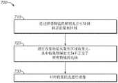
图7是根据本公开的一些实施例的用显微镜照明样品的方法的框图。方法700通常可由图1到6中所描述的一或多个光学系统执行。7 is a block diagram of a method of illuminating a sample with a microscope in accordance with some embodiments of the present disclosure.
方法700通常可从框710开始,其描述将照明光片通过照明物镜引导到样品的聚焦区域。例如,照明光学器件(例如,图1的120)可产生照明光片,并将其引导到照明物镜的后端。在一些实施例中,可基于显微镜的操作模式调整照明光片的性质(例如,宽度、NA)。照明物镜(例如,图1的122)可将照明光片引导到样品。在一些实施例中,照明光片可在其到达样品的途中穿过样品固持器的材料。在一些实施例中,照明光片可穿过照明物镜与样品之间的浸没流体。在一些实施例中,照明物镜可为空气物镜,且照明光片可穿过照明物镜与浸没流体之间的透镜或窗口(例如SIMlens、SIL)。
框710之后通常可接着框720,其描述通过收集物镜从聚焦区域收集光,其中收集物镜的光轴不正交于照明物镜的光轴。在一些实施例中,照明轴与收集轴之间的角可为锐角,例如45°角。在一些实施例中,角可更高或更低(例如,10°到80°)。在一些实施例中,收集物镜可为浸没物镜,且收集物镜的近端可与浸没流体接触。因此,可通过样品固持器及浸没流体将光收集到收集物镜中。
框720之后通常可接着框730,其描述对所收集的光进行成像。来自收集物镜的光可经引导到检测器(及/或目镜)上,检测器可用于向用户呈现图像。
在一些实施例中,收集光学器件可将所收集的光引导到远程图像,且额外物镜可以一定角对远程图像进行成像,所述角基于照明轴与收集轴之间的角。In some embodiments, the collection optics can direct the collected light to the remote image, and the additional objective lens can image the remote image at an angle based on the angle between the illumination axis and the collection axis.
在一些实施例中,方法700还可包含通过具有正交于照明轴的第二收集轴的第二收集物镜对样品进行成像。收集物镜及第二收集物镜可用作不同成像模式的部分。In some embodiments,
在一些实施例中,先前所描述的实施例可与常规(例如,正交)开顶式光片显微镜组合。例如,可能存在非正交收集物镜(例如,图1的主要收集物镜)及正交收集物镜,其每一者可使用相同的照明物镜。例如,图2展示相对于非正交收集物镜定向于45度的照明物镜,及位于非正交收集物镜的相对侧上的也定向于45度的第二正交收集物镜(相对于激发物镜形成90度角)。在这种组合式多模态系统中,非正交及正交收集路径可使用独立的光学路径单独处理或组合成单个光学路径(图3)。在一些实施例中,经组合系统提供多尺度成像能力,其中非正交布置提供高分辨率成像,且正交布置提供低到中等分辨率成像(图4)。In some embodiments, the previously described embodiments may be combined with conventional (eg, orthogonal) open-top light sheet microscopy. For example, there may be a non-orthogonal collection objective (eg, the main collection objective of Figure 1) and an orthogonal collection objective, each of which may use the same illumination objective. For example, Figure 2 shows an illumination objective oriented at 45 degrees relative to the non-orthogonal collection objective, and a second orthogonal collection objective located on the opposite side of the non-orthogonal collection objective also oriented at 45 degrees (formed relative to the excitation objective 90 degree angle). In this combined multimodal system, the non-orthogonal and orthogonal collection paths can be processed separately using separate optical paths or combined into a single optical path (Figure 3). In some embodiments, the combined system provides multi-scale imaging capabilities, with non-orthogonal arrangements providing high resolution imaging and orthogonal arrangements providing low to moderate resolution imaging (FIG. 4).
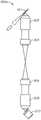
图8A到8D是根据本公开的一些实施例的不同重定向光学器件的示意图。图8A到8C是可用于重定向照明轴与收集轴之间的非正交角的重定向光学器件的示意图,而图8D是更详细地展示图8C的重定向光学器件800c的实例操作的示意图。图8A到8D的任何重定向光学器件中的任一者都可在本文先前所描述的显微镜中的任一者中使用。例如,在一些实施例中,重定向光学器件800a到800c中的任一者可包含在图2的重定向光学器件230及/或图3的重定向光学器件340中。由于图8A到8D描述相对于先前附图已描述的许多特征,因此为了简洁起见,将不再描述一些组件及特征。8A-8D are schematic diagrams of different redirecting optics according to some embodiments of the present disclosure. 8A-8C are schematic diagrams of redirecting optics that can be used to redirect non-orthogonal angles between the illumination axis and the collection axis, while FIG. 8D is a schematic diagram showing example operation of the redirecting
图8A展示使用检测器810的重定向光学器件800a,检测器810相对于所收集的光的光学路径倾斜。收集物镜802(例如,图2的204)以相对于照明聚焦平面801的非正交角收集光。管透镜804及806将光引导到额外收集物镜808,其将光的图像产生到检测器810上。与图2的230及图3的340中所展示的重定向光学器件不同,重定向光学器件800a以一定角将远程焦点直接投影到检测器810上,而不是使用额外的光学器件以一定角对远程焦点成像。Figure 8A shows
重定向光学器件800a可提供某些优点。例如,理想情况下,远程焦点应大致等于样本的折射率,样本的折射率在1.33到1.56的范围内。因此,远程焦点处的图像平面与样本中的图像平面大小大致相同。针对更高分辨率的成像,图像平面的大小通常约为0.5到1.0mm,这意味着检测器需要相同的大小,只有非常小的像素才能提供奈奎斯特采样(Nyquistsampling)。将倾斜检测器放置在此处而不是中间图像平面处的一个潜在优势是,图像平面保持45度,且不会更倾斜。Redirecting
图8B展示重定向光学器件800b,其中省略第二管透镜806及物镜808,而是管透镜804直接成像到检测器810上,检测器810相对于管透镜804(及物镜802)的光轴成一定角。管透镜804可提供样品内聚焦区域801的奈奎斯特采样。此图像平面的放大倍数在大约10倍的范围内。放大倍率的这种变化将使成角的图像平面在检测器处的角更大,这可能是不理想的。然而,这可通过使用具有特别小的像素尺寸的检测器来缓解。Figure 8B shows redirecting
图8C及8D展示重定向光学器件800c,其中可调谐透镜804用于将聚焦区域801的倾斜图像的焦点改变到检测器810上,检测器810相对于所收集的光的光轴不倾斜。可调谐透镜804的使用可允许通过使透镜的调谐与检测器810的操作(例如,与相机810的滚动快门)同步以重定向图像。图8D展示说明实例操作的示意图,其中可调谐透镜820(例如,光学器件800c的可调谐透镜804)用于随着检测器滚动快门在检测器810的表面上移动而改变倾斜焦光的哪个部分聚焦在检测器810上。Figures 8C and 8D
当然,应了解,根据本系统、装置及方法,本文所描述的实例、实施例或过程中的任一者可与一或多个其它实例、实施例及/或过程相结合,或在单独的装置或装置部分之间分离及/或执行。Of course, it should be appreciated that any of the examples, embodiments, or processes described herein may be combined with one or more other examples, embodiments, and/or processes, or in isolation, in accordance with the present systems, apparatus, and methods. Separation and/or execution between devices or device parts.
最后,上述讨论旨在仅说明本系统,且不应被解释为将所附权利要求书限于任何特定实施例或实施例组。因此,虽然已经参考示范性实施例详细描述本系统,但还应了解,所属领域的一般技术人员可在不偏离本系统更广泛及预期的精神及范围的情况下,设计许多修改及替代实施例,如以下权利要求书中所阐述。因此,说明书及附图以说明性方式看待,且不旨在限制所附权利要求书的范围。Finally, the above discussion is intended to be illustrative of the present system only, and should not be construed to limit the appended claims to any particular embodiment or group of embodiments. Thus, while the present system has been described in detail with reference to exemplary embodiments, it should also be understood that many modifications and alternative embodiments can be devised by those of ordinary skill in the art without departing from the broader and intended spirit and scope of the present system , as set forth in the following claims. Accordingly, the specification and drawings are to be viewed in an illustrative fashion, and are not intended to limit the scope of the appended claims.
Claims (41)
Applications Claiming Priority (3)
| Application Number | Priority Date | Filing Date | Title |
|---|---|---|---|
| US201962934758P | 2019-11-13 | 2019-11-13 | |
| US62/934,758 | 2019-11-13 | ||
| PCT/US2020/060530WO2021097300A1 (en) | 2019-11-13 | 2020-11-13 | Open-top light-sheet microscopy with a non-orthogonal arrangement of illumination and collection objectives |
Publications (2)
| Publication Number | Publication Date |
|---|---|
| CN114787684Atrue CN114787684A (en) | 2022-07-22 |
| CN114787684B CN114787684B (en) | 2024-09-10 |
Family
ID=75912904
Family Applications (1)
| Application Number | Title | Priority Date | Filing Date |
|---|---|---|---|
| CN202080084785.9AActiveCN114787684B (en) | 2019-11-13 | 2020-11-13 | Non-orthogonally arranged open-top light sheet microscope with illumination and collection objective |
Country Status (7)
| Country | Link |
|---|---|
| US (2) | US11644656B2 (en) |
| EP (1) | EP4058834A4 (en) |
| JP (1) | JP2023501581A (en) |
| KR (1) | KR20220115947A (en) |
| CN (1) | CN114787684B (en) |
| AU (1) | AU2020382640A1 (en) |
| WO (1) | WO2021097300A1 (en) |
Cited By (1)
| Publication number | Priority date | Publication date | Assignee | Title |
|---|---|---|---|---|
| CN117368210A (en)* | 2023-12-08 | 2024-01-09 | 荣旗工业科技(苏州)股份有限公司 | Defect detection method based on multi-dimensional composite imaging technology |
Families Citing this family (9)
| Publication number | Priority date | Publication date | Assignee | Title |
|---|---|---|---|---|
| EP3907548B1 (en)* | 2020-05-04 | 2024-01-10 | Leica Microsystems CMS GmbH | Light sheet microscope and method for imaging an object |
| US12217424B2 (en) | 2021-05-03 | 2025-02-04 | NeuraLight Ltd. | Determining digital markers indicative of a neurological condition using eye movement parameters |
| US12118825B2 (en) | 2021-05-03 | 2024-10-15 | NeuraLight Ltd. | Obtaining high-resolution oculometric parameters |
| EP4487159A1 (en)* | 2022-03-01 | 2025-01-08 | University of Washington | Apparatuses systems and methods for three dimensional microdissection of samples |
| DE102022125117A1 (en)* | 2022-09-29 | 2024-04-04 | Carl Zeiss Microscopy Gmbh | Light sheet microscope |
| WO2024129575A1 (en)* | 2022-12-12 | 2024-06-20 | Allen Institute | Selective-plane illumination microscopy with high étendue and long working distance objective lenses |
| WO2024147106A1 (en) | 2023-01-05 | 2024-07-11 | NeuraLight Ltd. | Estimating a delay from a monitor output to a sensor |
| US12217421B2 (en) | 2023-01-05 | 2025-02-04 | NeuraLight Ltd. | Point of gaze tracking with integrated calibration process |
| KR20250046859A (en) | 2023-09-27 | 2025-04-03 | 포항공과대학교 산학협력단 | Open-top Two-photon light sheet microscope and its operated method |
Citations (19)
| Publication number | Priority date | Publication date | Assignee | Title |
|---|---|---|---|---|
| US20070121107A1 (en)* | 2000-09-12 | 2007-05-31 | Kla-Tencor Technologies Corporation | Excimer laser inspection system |
| US20110122488A1 (en)* | 2009-10-29 | 2011-05-26 | California Institute Of Technology | Multiple-photon excitation light sheet illumination microscope |
| US20120049087A1 (en)* | 2010-08-25 | 2012-03-01 | California Institute Of Technology | Simultaneous orthogonal light sheet microscopy and computed optical tomography |
| CN103339547A (en)* | 2011-02-21 | 2013-10-02 | 莱卡微系统Cms有限责任公司 | Scanning microscope and method for the light-microscopic imaging of an object |
| CN105190399A (en)* | 2013-05-10 | 2015-12-23 | 欧洲分子生物学实验室 | Microscope module for sample imaging |
| US20160054553A1 (en)* | 2013-03-21 | 2016-02-25 | ETH Zürich | Method and device to achieve spatially confined photointeraction at the focal volume of a microscope |
| US20160154236A1 (en)* | 2013-07-10 | 2016-06-02 | Carl Zeiss Microscopy Gmbh | Assembly for Light Sheet Microscopy |
| US20160349495A1 (en)* | 2013-11-15 | 2016-12-01 | Cari Zeiss Microscopy GmbH | Arrangement for light sheet microscopy |
| CN107003508A (en)* | 2014-12-23 | 2017-08-01 | 通用电气医疗集团生物科学公司 | Selective Plane Illumination Microscopy Instruments |
| CN107667410A (en)* | 2015-05-21 | 2018-02-06 | 科磊股份有限公司 | It is included in the photocathode of the Flied emission pole array on the silicon substrate with boron layer |
| US20180088308A1 (en)* | 2016-09-28 | 2018-03-29 | University Of Washington | Inverted light-sheet microscope |
| US20180314047A1 (en)* | 2017-04-27 | 2018-11-01 | Olympus Corporation | Microscope |
| US20190064493A1 (en)* | 2016-02-26 | 2019-02-28 | University Of Southern California | Optimized Volumetric Imaging with Selective Volume Illumination and Light Field Detection |
| CN109799603A (en)* | 2017-11-16 | 2019-05-24 | 长光华大基因测序设备(长春)有限公司 | A kind of liquid submerges high-NA microcobjective and sequencing approach admittedly |
| US20190196172A1 (en)* | 2014-01-17 | 2019-06-27 | The Trustees Of Columbia University In The City Of New York | Systems and Methods for Three Dimensional Imaging |
| WO2019148008A1 (en)* | 2018-01-26 | 2019-08-01 | University Of Washington | Apparatuses and methods for multi-direction digital scanned light sheet microscopy |
| US10429629B1 (en)* | 2017-04-18 | 2019-10-01 | Veily Life Sciences LLC | Imaging and side-scatter photon detection using a single immersion objective |
| US20190310451A1 (en)* | 2016-11-10 | 2019-10-10 | The Trustees Of Columbia University In The City Of New York | Rapid High-Resolution Imaging Methods for Large Samples |
| CN110352373A (en)* | 2017-03-15 | 2019-10-18 | 卡尔蔡司显微镜有限责任公司 | Arrangement, microscope and the method for TIRF microscopy |
Family Cites Families (5)
| Publication number | Priority date | Publication date | Assignee | Title |
|---|---|---|---|---|
| US10908403B2 (en)* | 2011-02-14 | 2021-02-02 | European Molecular Biology Laboratory (Embl) | Light-pad microscope for high-resolution 3D fluorescence imaging and 2D fluctuation spectroscopy |
| WO2012122027A2 (en)* | 2011-03-04 | 2012-09-13 | The United States Of America, As Represented By The Secretary, Department Of Health And Human Services | Optomechanical module for converting a microscope to provide selective plane illumination microscopy |
| DE102012110077A1 (en)* | 2012-10-23 | 2014-06-26 | Karlsruher Institut für Technologie | Microscope with at least one illumination beam in the form of a lens |
| EP3198326A4 (en)* | 2014-09-24 | 2018-05-23 | The United States of America, as represented by The Secretary, Department of Health and Human Services | Resolution enhancement for light sheet microscopy systems and methods |
| DE102018115001A1 (en)* | 2018-06-21 | 2019-12-24 | Carl Zeiss Microscopy Gmbh | Procedure for calibrating a phase mask and microscope |
- 2020
- 2020-11-13JPJP2022527732Apatent/JP2023501581A/enactivePending
- 2020-11-13EPEP20886792.9Apatent/EP4058834A4/enactivePending
- 2020-11-13WOPCT/US2020/060530patent/WO2021097300A1/ennot_activeCeased
- 2020-11-13CNCN202080084785.9Apatent/CN114787684B/enactiveActive
- 2020-11-13KRKR1020227019919Apatent/KR20220115947A/enactivePending
- 2020-11-13AUAU2020382640Apatent/AU2020382640A1/enactivePending
- 2022
- 2022-05-05USUS17/737,736patent/US11644656B2/enactiveActive
- 2023
- 2023-03-23USUS18/189,018patent/US20230341669A1/enactivePending
Patent Citations (19)
| Publication number | Priority date | Publication date | Assignee | Title |
|---|---|---|---|---|
| US20070121107A1 (en)* | 2000-09-12 | 2007-05-31 | Kla-Tencor Technologies Corporation | Excimer laser inspection system |
| US20110122488A1 (en)* | 2009-10-29 | 2011-05-26 | California Institute Of Technology | Multiple-photon excitation light sheet illumination microscope |
| US20120049087A1 (en)* | 2010-08-25 | 2012-03-01 | California Institute Of Technology | Simultaneous orthogonal light sheet microscopy and computed optical tomography |
| CN103339547A (en)* | 2011-02-21 | 2013-10-02 | 莱卡微系统Cms有限责任公司 | Scanning microscope and method for the light-microscopic imaging of an object |
| US20160054553A1 (en)* | 2013-03-21 | 2016-02-25 | ETH Zürich | Method and device to achieve spatially confined photointeraction at the focal volume of a microscope |
| CN105190399A (en)* | 2013-05-10 | 2015-12-23 | 欧洲分子生物学实验室 | Microscope module for sample imaging |
| US20160154236A1 (en)* | 2013-07-10 | 2016-06-02 | Carl Zeiss Microscopy Gmbh | Assembly for Light Sheet Microscopy |
| US20160349495A1 (en)* | 2013-11-15 | 2016-12-01 | Cari Zeiss Microscopy GmbH | Arrangement for light sheet microscopy |
| US20190196172A1 (en)* | 2014-01-17 | 2019-06-27 | The Trustees Of Columbia University In The City Of New York | Systems and Methods for Three Dimensional Imaging |
| CN107003508A (en)* | 2014-12-23 | 2017-08-01 | 通用电气医疗集团生物科学公司 | Selective Plane Illumination Microscopy Instruments |
| CN107667410A (en)* | 2015-05-21 | 2018-02-06 | 科磊股份有限公司 | It is included in the photocathode of the Flied emission pole array on the silicon substrate with boron layer |
| US20190064493A1 (en)* | 2016-02-26 | 2019-02-28 | University Of Southern California | Optimized Volumetric Imaging with Selective Volume Illumination and Light Field Detection |
| US20180088308A1 (en)* | 2016-09-28 | 2018-03-29 | University Of Washington | Inverted light-sheet microscope |
| US20190310451A1 (en)* | 2016-11-10 | 2019-10-10 | The Trustees Of Columbia University In The City Of New York | Rapid High-Resolution Imaging Methods for Large Samples |
| CN110352373A (en)* | 2017-03-15 | 2019-10-18 | 卡尔蔡司显微镜有限责任公司 | Arrangement, microscope and the method for TIRF microscopy |
| US10429629B1 (en)* | 2017-04-18 | 2019-10-01 | Veily Life Sciences LLC | Imaging and side-scatter photon detection using a single immersion objective |
| US20180314047A1 (en)* | 2017-04-27 | 2018-11-01 | Olympus Corporation | Microscope |
| CN109799603A (en)* | 2017-11-16 | 2019-05-24 | 长光华大基因测序设备(长春)有限公司 | A kind of liquid submerges high-NA microcobjective and sequencing approach admittedly |
| WO2019148008A1 (en)* | 2018-01-26 | 2019-08-01 | University Of Washington | Apparatuses and methods for multi-direction digital scanned light sheet microscopy |
Cited By (2)
| Publication number | Priority date | Publication date | Assignee | Title |
|---|---|---|---|---|
| CN117368210A (en)* | 2023-12-08 | 2024-01-09 | 荣旗工业科技(苏州)股份有限公司 | Defect detection method based on multi-dimensional composite imaging technology |
| CN117368210B (en)* | 2023-12-08 | 2024-02-27 | 荣旗工业科技(苏州)股份有限公司 | Defect detection method based on multi-dimensional composite imaging technology |
Also Published As
| Publication number | Publication date |
|---|---|
| US11644656B2 (en) | 2023-05-09 |
| AU2020382640A1 (en) | 2022-05-19 |
| JP2023501581A (en) | 2023-01-18 |
| WO2021097300A1 (en) | 2021-05-20 |
| EP4058834A4 (en) | 2023-12-20 |
| US20230341669A1 (en) | 2023-10-26 |
| US20220260821A1 (en) | 2022-08-18 |
| KR20220115947A (en) | 2022-08-19 |
| EP4058834A1 (en) | 2022-09-21 |
| CN114787684B (en) | 2024-09-10 |
Similar Documents
| Publication | Publication Date | Title |
|---|---|---|
| CN114787684B (en) | Non-orthogonally arranged open-top light sheet microscope with illumination and collection objective | |
| US9383568B2 (en) | Objective-coupled selective plane illumination microscopy | |
| US8582203B2 (en) | Optical arrangement for oblique plane microscopy | |
| US9575308B2 (en) | Slide scanner with dynamic focus and specimen tilt and method of operation | |
| JP6557682B2 (en) | Functionally integrated laser scanning microscope | |
| EP1857853B1 (en) | Illuminating device | |
| US9804377B2 (en) | Low numerical aperture exclusion imaging | |
| US7480046B2 (en) | Scanning microscope with evanescent wave illumination | |
| JP2011215644A (en) | Microscope | |
| CN103852458B (en) | A kind of microscopic method based on wide field stimulated emission difference and device | |
| JP2025515943A (en) | Super-resolution single objective lens optical sheet microscopic imaging optical system and imaging system thereof | |
| JP6231154B2 (en) | Optical scanning system | |
| CN113316734A (en) | Light sheet microscope with turret lens | |
| US20220326502A1 (en) | Apparatuses, systems and methods for solid immersion meniscus lenses |
Legal Events
| Date | Code | Title | Description |
|---|---|---|---|
| PB01 | Publication | ||
| PB01 | Publication | ||
| SE01 | Entry into force of request for substantive examination | ||
| SE01 | Entry into force of request for substantive examination | ||
| GR01 | Patent grant | ||
| GR01 | Patent grant |