CN114786607A - System and method for turbinate reduction - Google Patents
System and method for turbinate reductionDownload PDFInfo
- Publication number
- CN114786607A CN114786607ACN202080086309.0ACN202080086309ACN114786607ACN 114786607 ACN114786607 ACN 114786607ACN 202080086309 ACN202080086309 ACN 202080086309ACN 114786607 ACN114786607 ACN 114786607A
- Authority
- CN
- China
- Prior art keywords
- electrode
- tissue
- turbinate
- distal
- edge
- Prior art date
- Legal status (The legal status is an assumption and is not a legal conclusion. Google has not performed a legal analysis and makes no representation as to the accuracy of the status listed.)
- Granted
Links
Images


Classifications
- A—HUMAN NECESSITIES
- A61—MEDICAL OR VETERINARY SCIENCE; HYGIENE
- A61B—DIAGNOSIS; SURGERY; IDENTIFICATION
- A61B18/00—Surgical instruments, devices or methods for transferring non-mechanical forms of energy to or from the body
- A61B18/04—Surgical instruments, devices or methods for transferring non-mechanical forms of energy to or from the body by heating
- A61B18/12—Surgical instruments, devices or methods for transferring non-mechanical forms of energy to or from the body by heating by passing a current through the tissue to be heated, e.g. high-frequency current
- A61B18/14—Probes or electrodes therefor
- A61B18/1477—Needle-like probes
- A—HUMAN NECESSITIES
- A61—MEDICAL OR VETERINARY SCIENCE; HYGIENE
- A61B—DIAGNOSIS; SURGERY; IDENTIFICATION
- A61B18/00—Surgical instruments, devices or methods for transferring non-mechanical forms of energy to or from the body
- A61B18/04—Surgical instruments, devices or methods for transferring non-mechanical forms of energy to or from the body by heating
- A61B18/12—Surgical instruments, devices or methods for transferring non-mechanical forms of energy to or from the body by heating by passing a current through the tissue to be heated, e.g. high-frequency current
- A61B18/14—Probes or electrodes therefor
- A61B18/1485—Probes or electrodes therefor having a short rigid shaft for accessing the inner body through natural openings
- A—HUMAN NECESSITIES
- A61—MEDICAL OR VETERINARY SCIENCE; HYGIENE
- A61B—DIAGNOSIS; SURGERY; IDENTIFICATION
- A61B18/00—Surgical instruments, devices or methods for transferring non-mechanical forms of energy to or from the body
- A61B2018/00315—Surgical instruments, devices or methods for transferring non-mechanical forms of energy to or from the body for treatment of particular body parts
- A61B2018/00321—Head or parts thereof
- A61B2018/00327—Ear, nose or throat
- A—HUMAN NECESSITIES
- A61—MEDICAL OR VETERINARY SCIENCE; HYGIENE
- A61B—DIAGNOSIS; SURGERY; IDENTIFICATION
- A61B18/00—Surgical instruments, devices or methods for transferring non-mechanical forms of energy to or from the body
- A61B2018/00571—Surgical instruments, devices or methods for transferring non-mechanical forms of energy to or from the body for achieving a particular surgical effect
- A61B2018/00577—Ablation
- A61B2018/00583—Coblation, i.e. ablation using a cold plasma
- A—HUMAN NECESSITIES
- A61—MEDICAL OR VETERINARY SCIENCE; HYGIENE
- A61B—DIAGNOSIS; SURGERY; IDENTIFICATION
- A61B18/00—Surgical instruments, devices or methods for transferring non-mechanical forms of energy to or from the body
- A61B18/04—Surgical instruments, devices or methods for transferring non-mechanical forms of energy to or from the body by heating
- A61B18/12—Surgical instruments, devices or methods for transferring non-mechanical forms of energy to or from the body by heating by passing a current through the tissue to be heated, e.g. high-frequency current
- A61B18/1206—Generators therefor
- A61B2018/1213—Generators therefor creating an arc
- A—HUMAN NECESSITIES
- A61—MEDICAL OR VETERINARY SCIENCE; HYGIENE
- A61B—DIAGNOSIS; SURGERY; IDENTIFICATION
- A61B2218/00—Details of surgical instruments, devices or methods for transferring non-mechanical forms of energy to or from the body
- A61B2218/001—Details of surgical instruments, devices or methods for transferring non-mechanical forms of energy to or from the body having means for irrigation and/or aspiration of substances to and/or from the surgical site
- A61B2218/002—Irrigation
- A—HUMAN NECESSITIES
- A61—MEDICAL OR VETERINARY SCIENCE; HYGIENE
- A61B—DIAGNOSIS; SURGERY; IDENTIFICATION
- A61B2218/00—Details of surgical instruments, devices or methods for transferring non-mechanical forms of energy to or from the body
- A61B2218/001—Details of surgical instruments, devices or methods for transferring non-mechanical forms of energy to or from the body having means for irrigation and/or aspiration of substances to and/or from the surgical site
- A61B2218/007—Aspiration
Landscapes
- Health & Medical Sciences (AREA)
- Surgery (AREA)
- Engineering & Computer Science (AREA)
- Life Sciences & Earth Sciences (AREA)
- Biomedical Technology (AREA)
- Otolaryngology (AREA)
- Nuclear Medicine, Radiotherapy & Molecular Imaging (AREA)
- Plasma & Fusion (AREA)
- Physics & Mathematics (AREA)
- Heart & Thoracic Surgery (AREA)
- Medical Informatics (AREA)
- Molecular Biology (AREA)
- Animal Behavior & Ethology (AREA)
- General Health & Medical Sciences (AREA)
- Public Health (AREA)
- Veterinary Medicine (AREA)
- Surgical Instruments (AREA)
Abstract
Description
Translated fromChinese相关申请的交叉引用CROSS-REFERENCE TO RELATED APPLICATIONS
本申请要求于2019年12月19日提交的、标题为“用于鼻甲缩减的系统和方法(SYSTEMS AND METHODS FOR TURBINATE REDUCTION)”并通过引用整体并入本文的临时专利申请第62/950,632号的权益。This application claims Provisional Patent Application No. 62/950,632, filed on December 19, 2019, entitled "SYSTEMS AND METHODS FOR TURBINATE REDUCTION" and incorporated herein by reference in its entirety rights and interests.
技术领域technical field
本发明涉及外科领域,并且更具体地,涉及使用电外科手术进行鼻甲缩减的系统和方法。The present invention relates to the field of surgery and, more particularly, to systems and methods for turbinate reduction using electrosurgery.
背景技术Background technique
一种常见的鼻部症状,流鼻涕(例如,过敏性鼻炎或血管舒缩性鼻炎),通常是由鼻子中称为鼻甲的小架子状结构引起的。鼻甲负责加温和加湿通过鼻子进入肺部的空气。当空气中含有刺激物时,鼻甲会通过肿胀和倒出粘液来对气载颗粒做出反应,就好像身体试图阻塞和清洁呼吸通道一样。为了暂时缓解鼻甲肿胀,通常会开出减充血剂鼻腔喷雾剂和丸剂。然而,这些措施的效果有限,并且长期使用这样的鼻腔喷雾剂通常会使问题变得更糟。此外,减充血剂丸剂可能会导致高血压、增加心率,并且对某些人来说,还会导致失眠。A common nasal symptom, a runny nose (eg, allergic rhinitis or vasomotor rhinitis), is usually caused by small shelf-like structures in the nose called turbinates. The turbinates are responsible for heating and humidifying the air that passes through the nose and into the lungs. When the air contains irritants, the turbinates respond to airborne particles by swelling and pouring out mucus, as if the body were trying to block and clear the airway. To temporarily relieve swelling of the turbinates, decongestant nasal sprays and pills are often prescribed. However, these measures have limited effectiveness, and long-term use of such nasal sprays often makes the problem worse. Additionally, decongestant pills may cause high blood pressure, increase heart rate, and, in some people, insomnia.
在过去的几年里,包括去除一部分鼻甲的治疗已经显示出一些希望。例如,动力棒(如微型吸切器棒)已被用于机械去除部分鼻甲。微型吸切器是一次性电动切割器,具有带有用于切割和切除组织的锯齿状远侧尖端的旋转轴。微型吸切器的手柄通常是中空的,并且它容纳小型真空吸尘器,所述小型真空吸尘器用于抽吸由旋转切割器形成的碎屑。然而,微型吸切器存在许多缺点。一方面,鼻腔中的组织是血管性的,而微型吸切器会切断该组织内的血管,通常会导致大量出血,从而阻碍外科医生对目标部位的观察。因此,通常必须定期从鼻子取出微型吸切器以烧灼切断的血管,这会延长手术时间。此外,微型吸切器并不精确,并且在手术期间通常难以区分目标组织和鼻子内的其他结构,例如软骨、骨或颅骨。因此,外科医生必须非常小心以尽量减少对鼻内软骨和骨的损伤,并避免损伤神经,例如视神经。Over the past few years, treatments that include removing part of the turbinate have shown some promise. For example, powered rods (eg, micro-aspirator rods) have been used to mechanically remove parts of the turbinates. The Micro Aspirator is a single-use electric cutter with a rotating shaft with a serrated distal tip for cutting and resecting tissue. The handle of the mini suction cutter is usually hollow, and it accommodates a small vacuum cleaner for suctioning the debris formed by the rotary cutter. However, there are a number of disadvantages to micro suction cutters. On the one hand, the tissue in the nasal cavity is vascular, and the microsuction cutters sever the blood vessels within that tissue, often resulting in profuse bleeding that obstructs the surgeon's view of the target site. Therefore, microsuction cutters must be periodically removed from the nose to cauterize the severed blood vessels, which prolongs the operation time. Additionally, microsuction cutters are imprecise, and during surgery it is often difficult to differentiate the target tissue from other structures within the nose, such as cartilage, bone, or skull. Therefore, the surgeon must be very careful to minimize damage to the cartilage and bone within the nose, and to avoid damage to nerves such as the optic nerve.
先前已描述了用于鼻甲缩减的涉及基于电外科能量棒的治疗。通常以双极布置构造的电外科治疗电极可以插入鼻甲中,并且可以分子解离组织,从而去除鼻甲的一部分,同时在发生任何出血时提供选择性凝固。这样的方法和装置在先前提交的申请,美国专利第9,254,166号和第9,649,144号中进行了更全面的描述,其全部公开内容已通过引用并入。然而,这些棒可能需要使用单独的装置(例如Cottle-tip提升器)才能进入鼻甲;并且使用它可能会增加手术时间和成本。因此,需要一种能够缩减鼻甲组织同时提供到鼻甲的通路的电外科装置。Treatment involving electrosurgical energy bars for turbinate reduction has been previously described. Electrosurgical electrodes, typically configured in a bipolar arrangement, can be inserted into the turbinate and can molecularly dissociate the tissue, thereby removing a portion of the turbinate while providing selective coagulation in the event of any bleeding. Such methods and apparatus are more fully described in previously filed applications, US Pat. Nos. 9,254,166 and 9,649,144, the entire disclosures of which are incorporated by reference. However, these rods may require the use of a separate device (eg, a Cottle-tip lifter) to access the turbinate; and using it may increase the time and cost of the procedure. Therefore, there is a need for an electrosurgical device that can reduce turbinate tissue while providing access to the turbinate.
先前描述的电外科棒的直径也更大(大约4-5mm),这可以有利地使吸入管线中的堵塞最小化;然而,相对于小尺寸的鼻甲,直径减小到2-3mm的棒可能会减少组织损伤,并使放置在鼻甲内更容易,从而减少手术时间和失血。因此,需要一种优选小于3mm的小直径棒,其提供受控的鼻甲缩减、具有最小堵塞的凝固以减少手术成本、时间以及易用性。The previously described electrosurgical rods are also larger in diameter (approximately 4-5mm), which can advantageously minimise blockage in the suction line; however, rods reduced to 2-3mm in diameter relative to the small size turbinates may Will reduce tissue damage and allow easier placement within the turbinate, thereby reducing operative time and blood loss. Therefore, there is a need for a small diameter rod, preferably less than 3 mm, that provides controlled turbinate reduction, coagulation with minimal blockage to reduce surgical cost, time, and ease of use.
鼻甲治疗也是在治疗部位的模糊观察的情况下进行的,因此难以实现精确的治疗。因此,需要提供一种装置和方法,其提供关于鼻甲内的治疗位置的定位的反馈或指导,而无需直接可视化。Turbinate treatment is also performed with a blurred view of the treatment site, so it is difficult to achieve precise treatment. Therefore, there is a need to provide a device and method that provides feedback or guidance on the positioning of the treatment site within the turbinate without direct visualization.
附图说明Description of drawings
对于示例性实施例的详细描述,现在将参考附图,其中:For the detailed description of the exemplary embodiments, reference will now be made to the accompanying drawings, in which:
图1示出了根据至少某些实施例的电外科系统的透视图;1 shows a perspective view of an electrosurgical system in accordance with at least some embodiments;
图2A示意性地示出了根据至少某些实施例的用于治疗组织的棒的等距视图;Figure 2A schematically illustrates an isometric view of a wand for treating tissue in accordance with at least some embodiments;
图2B示意性地示出了根据至少某些实施例的棒的横截面;Figure 2B schematically illustrates a cross-section of a rod in accordance with at least some embodiments;
图2C示意性地示出了图2B中所示的棒远端的横截面;Figure 2C schematically shows a cross section of the distal end of the rod shown in Figure 2B;
图2D示意性地示出了至少在图2C中示出的棒远端的等距视图;Figure 2D schematically shows an isometric view of at least the distal end of the rod shown in Figure 2C;
图2E示意性地示出了至少在图2C中示出的棒远端部分的俯视图;Figure 2E schematically shows a top view of at least the distal end portion of the rod shown in Figure 2C;
图2F示意性地示出了至少在图2C中示出的棒远端部分的侧视图;Figure 2F schematically shows a side view of at least the distal end portion of the rod shown in Figure 2C;
图2G示意性地示出了至少在图2C中示出的棒远端的等距视图;Figure 2G schematically shows an isometric view of at least the distal end of the rod shown in Figure 2C;
图2H示意性地示出了根据至少某些实施例的棒远端部分的横向横截面;Figure 2H schematically illustrates a transverse cross-section of a distal end portion of a rod in accordance with at least some embodiments;
图2I示意性地示出了根据至少某些实施例的具有半透明外轴的棒远端;Figure 2I schematically illustrates a distal end of a rod with a translucent outer shaft in accordance with at least some embodiments;
图3A和3B示意性地示出了根据至少某些实施例的用于流体联接到棒的流体管的切换阀选项;以及Figures 3A and 3B schematically illustrate switching valve options for fluid tubes fluidly coupled to wands in accordance with at least some embodiments; and
图4A示意性地示出了根据至少某些实施例的用于治疗组织的棒远端的等距视图;4A schematically illustrates an isometric view of a distal end of a rod for treating tissue in accordance with at least some embodiments;
图4B示意性地示出了至少在图4A中示出的棒远端的横截面;Figure 4B schematically shows a cross-section of at least the distal end of the rod shown in Figure 4A;
图5示出了根据至少某些实施例的具有延伸提升器尖端的棒远端的替代实施例的侧视图;Figure 5 shows a side view of an alternate embodiment of a rod distal end with an extended riser tip in accordance with at least some embodiments;
图6A示出了根据至少某些实施例的用棒实施例治疗鼻甲的方法;Figure 6A illustrates a method of treating a turbinate with a rod embodiment, according to at least some embodiments;
图6B示出了根据至少某些实施例的用具有提升器尖端的替代实施例的棒实施例来治疗鼻甲的方法;6B illustrates a method of treating a turbinate with an alternative embodiment of a wand embodiment having a lifter tip, in accordance with at least some embodiments;
图7A示出了根据至少某些实施例的用于治疗鼻甲的棒的替代实施例;Figure 7A illustrates an alternative embodiment of a wand for treating turbinates in accordance with at least some embodiments;
图7B示出了根据至少某些实施例的用于治疗鼻甲的棒远端的等距视图;Figure 7B shows an isometric view of the distal end of a wand for treating turbinates in accordance with at least some embodiments;
图7C示出了至少在图7B中示出的棒远端的侧视图;Figure 7C shows a side view of at least the distal end of the rod shown in Figure 7B;
图7D示出了至少在图7B中示出的棒远端实施例的横截面;Figure 7D shows a cross-section of at least the rod distal end embodiment shown in Figure 7B;
图7E示出了至少在图7B中示出的棒远端的端视图;Figure 7E shows an end view of at least the distal end of the rod shown in Figure 7B;
图7F示出了至少在图7B中示出的棒远端实施例的电极;Figure 7F shows the electrodes of at least the rod distal end embodiment shown in Figure 7B;
图7G示出了至少在图7B中示出的棒远端实施例的流体输送部分;Figure 7G shows at least the fluid delivery portion of the distal end embodiment of the rod shown in Figure 7B;
图8A示出了根据至少某些实施例的用于治疗鼻甲的棒远端的替代实施例的等距视图;8A shows an isometric view of an alternate embodiment of the distal end of a wand for treating turbinates, in accordance with at least some embodiments;
图8B示出了至少在图8A中示出的替代远端实施例的侧视图;Figure 8B shows a side view of at least the alternative distal embodiment shown in Figure 8A;
图8C示出了至少在图8A中示出的替代远端实施例的横截面图;以及Figure 8C shows a cross-sectional view of at least the alternative distal embodiment shown in Figure 8A; and
图8D示出了至少在图8A中示出的替代远端实施例的端视图。Figure 8D shows an end view of at least the alternative distal embodiment shown in Figure 8A.
发明内容SUMMARY OF THE INVENTION
一般而言,本公开描述了一种双极的电外科装置或棒以将组织效应限制在预期区域。装置直径优选地是小直径(小于3mm)并且构造成接近和治疗鼻甲组织。治疗组织可以包括以下的至少一种:缩减鼻甲体积,缩减鼻甲体积并伴随止血以减少出血,以及通过热收缩和凝固鼻甲来缩减。该棒还包括可以提供对鼻甲的初始刺穿和接近目标组织的远侧提升器尖端。尖端也可以用作参考定位器,用于将有源电极更中心地放置在鼻甲内。尖端还可以限定犁状表面,所述犁状表面引导松散的组织远离装置的抽入孔,从而防止组织堵塞吸入路径。In general, the present disclosure describes a bipolar electrosurgical device or rod to confine tissue effects to a desired area. The device diameter is preferably a small diameter (less than 3 mm) and is configured to access and treat turbinate tissue. Treating the tissue may include at least one of: reducing the volume of the turbinate, reducing the volume of the turbinate with hemostasis to reduce bleeding, and reducing the volume of the turbinate by heat shrinking and coagulating the turbinate. The wand also includes a distal lifter tip that can provide initial penetration of the turbinate and access to the target tissue. The tip can also be used as a reference locator for placing the active electrode more centrally within the turbinate. The tip may also define a plough-like surface that guides loose tissue away from the suction hole of the device, thereby preventing tissue from blocking the suction path.
公开了用于缩减鼻甲的电外科装置的第一示例性实施例,其可以包括手柄和从其延伸的细长轴。轴限定纵向轴线,轴远端限定工作部分。该工作部分包括提升器尖端主体,所述提升器尖端主体逐渐变细以限定前缘,所述前缘是非钝的并且可以刺穿组织。例如,该前缘可以构造成刺穿鼻甲以将有源电极放置在鼻甲内。前缘限定在第一方向上围绕纵向轴线延伸的弧,并且提升器尖端主体从前缘向近侧弯曲,限定面向远侧的凸曲面。提升器尖端主体凸曲面延伸跨越和横穿纵向轴线。提升器尖端主体是导电的并且可以限定装置的返回电极。装置还包括有源电极,所述有源电极在近侧与前缘间隔开并与提升器尖端主体电隔离。有源电极包括通过其中的与负压源流体连通的孔。装置还可以包括内管,所述内管流体联接到负压源和有源电极孔并同轴设置在细长轴内。A first exemplary embodiment of an electrosurgical device for reducing a turbinate is disclosed, which may include a handle and an elongated shaft extending therefrom. The shaft defines a longitudinal axis and the distal end of the shaft defines a working portion. The working portion includes a lifter tip body that tapers to define a leading edge that is non-blunt and can pierce tissue. For example, the leading edge can be configured to pierce the turbinate to place the active electrode within the turbinate. The leading edge defines an arc extending in a first direction about the longitudinal axis, and the riser tip body curves proximally from the leading edge to define a distally facing convex curve. The riser tip body convex surface extends across and across the longitudinal axis. The lifter tip body is conductive and can define the return electrode of the device. The device also includes an active electrode proximally spaced from the leading edge and electrically isolated from the lifter tip body. The active electrode includes an aperture therethrough in fluid communication with a source of negative pressure. The device may also include an inner tube fluidly coupled to the negative pressure source and the active electrode bore and disposed coaxially within the elongated shaft.
在一些示例性实施例中,提升器尖端主体曲面限定面向远侧的弯曲表面,所述面向远侧的弯曲表面构造成引导已被前缘刺穿并由此松开的组织远离有源电极孔。在一些示例性实施例中,提升器尖端主体构造成减少内管的堵塞。在一些示例性实施例中,前缘构造成接合鼻甲骨并将有源电极与鼻甲骨间隔开。在一些示例性实施例中,提升器尖端主体构造成引导装置通过鼻甲的运动以最小化通过鼻甲的切口扩张。在一些示例性实施例中,提升器尖端前缘与平面重合,所述平面平行于纵向轴线并且比有源电极在径向上离纵向轴线更远。在一些示例性实施例中,提升器尖端主体限定等于或大于细长轴的最大外径的最大宽度。在一些示例性实施例中,有源电极限定环,孔由环的内边界限定。环的单侧的横向尺寸显著小于孔的相应横向尺寸。在一些示例性实施例中,有源电极嵌套在电绝缘间隔件内,间隔件构造成引导松散的组织块远离有源电极孔。该绝缘间隔件可以限定第二参考表面,所述第二参考表面在鼻甲缩减期间接合鼻甲骨并且将有源电极与鼻甲骨间隔开。装置还可以包括流体输送结构,所述流体输送结构流体联接到装置外部的流体源。装置可以具有在装置远端部分处的流体输送孔作为有源电极,所述流体输送孔口通过远端部分的相对侧上的轴的一部分。In some exemplary embodiments, the lifter tip body curvature defines a distally facing curved surface configured to guide tissue that has been pierced by the leading edge and thereby loosened away from the active electrode aperture . In some exemplary embodiments, the riser tip body is configured to reduce clogging of the inner tube. In some exemplary embodiments, the leading edge is configured to engage the turbinate and space the active electrode from the turbinate. In some exemplary embodiments, the lifter tip body is configured to guide movement of the device through the turbinate to minimize incision expansion through the turbinate. In some exemplary embodiments, the riser tip leading edge coincides with a plane that is parallel to the longitudinal axis and radially further from the longitudinal axis than the active electrode. In some exemplary embodiments, the riser tip body defines a maximum width that is equal to or greater than the maximum outer diameter of the elongated shaft. In some exemplary embodiments, the active electrode defines a ring, and the aperture is defined by the inner boundary of the ring. The lateral dimension of one side of the ring is significantly smaller than the corresponding lateral dimension of the hole. In some exemplary embodiments, the active electrode is nested within an electrically insulating spacer configured to guide the loose tissue mass away from the active electrode aperture. The insulating spacer may define a second reference surface that engages the turbinate during turbinate reduction and separates the active electrode from the turbinate. The device may also include a fluid delivery structure fluidly coupled to a fluid source external to the device. The device may have a fluid delivery orifice at the distal portion of the device as the active electrode, the fluid delivery orifice passing through a portion of the shaft on the opposite side of the distal portion.
本文还公开了缩减鼻甲的示例性方法,该方法包括用电外科器械的锋利前缘刺穿鼻甲。无需向器械供应能量即可实现刺穿。锋利前缘可以与器械的主要纵向轴线重合。替代地,锋利前缘可以与器械的纵向轴线重合。该方法还可以包括将鼻甲骨表面与锋利前缘接合,并且器械的第二参考表面在近侧与锋利前缘间隔开,由此将有源电极远离鼻甲骨放置。第二参考表面可以是绝缘间隔件的外表面。该方法还可以包括在电联接到器械的电外科发生器上选择组织治疗模式并向有源电极供应能量以缩减鼻甲,并且在保持骨表面和锋利前缘之间的接合的同时使有源电极移动通过鼻甲以缩减鼻甲。Also disclosed herein is an exemplary method of reducing the turbinate, the method comprising piercing the turbinate with a sharp leading edge of an electrosurgical instrument. Piercing can be achieved without supplying energy to the instrument. The sharp leading edge may coincide with the main longitudinal axis of the instrument. Alternatively, the sharp leading edge may coincide with the longitudinal axis of the instrument. The method may further include engaging the turbinate surface with the sharp leading edge and the second reference surface of the instrument proximally spaced from the sharp leading edge, thereby placing the active electrode away from the turbinate. The second reference surface may be the outer surface of the insulating spacer. The method may also include selecting a tissue treatment mode on an electrosurgical generator electrically coupled to the instrument and supplying energy to the active electrode to reduce the turbinate and causing the active electrode to maintain engagement between the bone surface and the sharp leading edge while maintaining engagement Move through the turbinate to reduce the turbinate.
在一些示例性方法中,选择组织治疗模式包括从高减体积模式、中等减体积模式和热加热或收缩模式中进行选择。中等减体积模式可以包括在足以缩减鼻甲体积的高电压和配置成热治疗组织的较低电压之间将电压脉冲输送到组织。低模式可以包括输送足以加热相邻组织的低电压,并具有周期性的高压脉冲以推动组织远离有源电极并减少组织粘连。选择模式还可以选择导电流体到鼻甲组织的流体输送速率。该方法还可以包括通过穿过有源电极的孔抽吸流体和组织碎屑。在刺穿鼻甲的同时,在一些示例性方法中,松散的鼻甲组织可以被引导远离有源电极,其中面向远侧的弯曲表面从锋利前缘向近侧延伸。In some exemplary methods, selecting the tissue treatment mode includes selecting from a high volume reduction mode, a moderate volume reduction mode, and a thermal heating or contraction mode. The moderate volume reduction mode may include delivering voltage pulses to the tissue between a high voltage sufficient to reduce the volume of the turbinate and a lower voltage configured to thermally treat the tissue. The low mode may include delivering a low voltage sufficient to heat adjacent tissue, with periodic high voltage pulses to push tissue away from the active electrode and reduce tissue adhesion. Selecting the mode also selects the rate of fluid delivery of the conductive fluid to the turbinate tissue. The method can also include aspirating fluid and tissue debris through the hole through the active electrode. While piercing the turbinate, in some exemplary methods, loose turbinate tissue may be directed away from the active electrode, with the distally facing curved surface extending proximally from the sharp leading edge.
本文公开了用于治疗鼻甲的另一示例性实施例电外科装置,其包括手柄和轴。轴限定主要纵向轴线和延伸通过其中的导管。轴包括非绝缘的远端部分,所述远端部分包括第一电极。该第一电极可以配置为返回电极。第一电极可以包括可以具有暴露的电外科表面的最远侧边缘,最远侧边缘构造成机械地穿透组织。弧形表面可以从最远侧边缘沿着主要纵向轴线向近侧延伸,弧形表面是限定凸方向的凸表面。第一电极还可以包括限定弧形表面的侧向边缘的第一弧形边缘和第二弧形边缘,并且侧向边缘可以限定暴露的电外科表面。第一电极还可以包括在近侧与最远侧边缘间隔开并且在凸方向的相对侧上的导管开口。第二电极可以嵌套在导管开口内,并且与第一电极电隔离,第二电极限定具有通过其中的单个孔的环,单个孔与沿着轴导管延伸的流体抽吸结构流体连通。Disclosed herein is another exemplary embodiment electrosurgical device for treating turbinates that includes a handle and a shaft. The shaft defines a major longitudinal axis and a conduit extending therethrough. The shaft includes a non-insulated distal portion that includes a first electrode. The first electrode may be configured as a return electrode. The first electrode can include a distal-most edge that can have an exposed electrosurgical surface, the distal-most edge being configured to mechanically penetrate tissue. An arcuate surface may extend proximally along the major longitudinal axis from the distal-most edge, the arcuate surface being a convex surface defining a convex direction. The first electrode can also include a first arcuate edge and a second arcuate edge that define lateral edges of the arcuate surface, and the lateral edges can define an exposed electrosurgical surface. The first electrode may also include a catheter opening spaced proximally from the distal-most edge and on opposite sides of the convex direction. The second electrode may be nested within the conduit opening and electrically isolated from the first electrode, the second electrode defining a ring having a single aperture therethrough in fluid communication with a fluid suction structure extending along the shaft conduit.
在一些示例性实施例中,孔限定的宽度基本上大于有源电极环的对应宽度。例如,孔宽度是电极环的单腿或侧的宽度的至少两倍。在一些示例性实施例中,轴远端限定包括最远侧边缘的提升器尖端,并且其中面向远侧的弯曲表面从最远侧边缘向近侧延伸。最远侧边缘可以与纵向轴线重合。最远侧边缘可以与平行于纵向轴线并且比有源环电极在径向上离纵向轴线更远的平面重合。面向远侧的弯曲表面可以构造成引导已被前缘刺穿并且由此松开的组织远离有源电极孔。In some exemplary embodiments, the apertures define a width that is substantially greater than the corresponding width of the active electrode ring. For example, the aperture width is at least twice the width of a single leg or side of the electrode ring. In some exemplary embodiments, the distal end of the shaft defines a lifter tip that includes a distal-most edge, and wherein the distally-facing curved surface extends proximally from the distal-most edge. The distal-most edge may coincide with the longitudinal axis. The distal-most edge may coincide with a plane parallel to the longitudinal axis and radially further from the longitudinal axis than the active ring electrode. The distally facing curved surface can be configured to guide tissue that has been pierced by the leading edge and thereby loosened away from the active electrode aperture.
公开了一种用于体积去除组织的另一示例性电外科装置,其包括手柄端和工作远端,外轴在其间延伸。外轴具有纵向轴线,并且工作远端终止于最远侧前缘。该前缘限定非钝前缘,所述非钝前缘限定围绕纵向轴线的连续曲线。连续曲线的至少一部分与纵向轴线相交并横穿纵向轴线。包括前缘的工作端可以电联接到电外科电源并且配置为返回电极。内管可以与外轴同轴地延伸。内管可以流体联接到真空源。内管可以是导电的并且可以联接到电源。内管远端嵌套在电绝缘间隔件内并且配置为有源电极。内管还包括与有源电极重合的通过其中的吸入孔。装置还包括至少部分地由外轴和电绝缘间隔件的外表面限定的流体输送导管,外表面进一步限定用于沿着间隔件外表面形成多个流体输送通道的轴向肋,多个通道具有通过外轴并与轴向肋重合的第一出口和邻近有源电极的多个其他出口。Another exemplary electrosurgical device for volumetric tissue removal is disclosed that includes a handle end and a working distal end with an outer shaft extending therebetween. The outer shaft has a longitudinal axis and the working distal end terminates at the distal-most leading edge. The leading edge defines a non-blunt leading edge that defines a continuous curve about the longitudinal axis. At least a portion of the continuous curve intersects and traverses the longitudinal axis. The working end including the leading edge can be electrically coupled to the electrosurgical power source and configured as a return electrode. The inner tube may extend coaxially with the outer shaft. The inner tube can be fluidly coupled to a vacuum source. The inner tube can be conductive and can be coupled to a power source. The inner tube distal end is nested within the electrically insulating spacer and configured as an active electrode. The inner tube also includes a suction hole therethrough coinciding with the active electrode. The device also includes a fluid delivery conduit defined at least in part by the outer shaft and an outer surface of the electrically insulating spacer, the outer surface further defining axial ribs for forming a plurality of fluid delivery channels along the outer surface of the spacer, the plurality of channels having A first outlet passing through the outer shaft and coinciding with the axial rib and a plurality of other outlets adjacent to the active electrode.
在一些示例性实施例中,轴向肋具有近侧部分,所述近侧部分限定一直到并包括第一出口的第一肋宽度以及一直延伸到并包括间隔件的最远端的第二较宽肋宽度。内管可以从有源电极延伸到手柄。内管可以由钴合金形成。内管可以流体联接到第二孔,所述第二孔通过棒手柄设置并且构造成可选择地被覆盖以控制通过吸入孔的吸入。可以选择性地且至少部分地覆盖第二孔以在凝固和消融之间调整有源电极处的组织效应。内管可以终止于跨越内管范围的面向远侧的正交表面,限定吸入孔的周边的至少一部分。In some exemplary embodiments, the axial rib has a proximal portion that defines a first rib width up to and including the first outlet and a second relatively large portion extending up to and including the distal-most end of the spacer Wide rib width. The inner tube can extend from the active electrode to the handle. The inner tube may be formed from a cobalt alloy. The inner tube may be fluidly coupled to a second aperture provided by the wand handle and configured to be selectively covered to control suction through the suction aperture. The second hole can be selectively and at least partially covered to adjust tissue effects at the active electrode between coagulation and ablation. The inner tube may terminate in a distally facing orthogonal surface spanning the extent of the inner tube, defining at least a portion of the perimeter of the suction aperture.
公开了附加的示例性电外科器械,其包括形成有源电极的内管状构件,在内管状构件的远端处具有通过其中的孔。内管状构件还包括流体联接到孔的中心管腔,用于通过其中选择性地去除流体和组织,内管状构件终止于正交的面向远侧的表面,所述表面具有沿其的表面粗糙。器械还包括外管状构件,所述外管状构件包括近侧部段、远侧尖端和从近侧部段延伸到在近侧与远侧尖端间隔开的窗口的中心管腔。管腔尺寸确定成容纳内管状构件,窗口尺寸确定成暴露内管状构件的一部分以限定有源电极,并且远侧尖端形成向远侧延伸到有源电极并终止于构造成刺穿接触组织的前缘的提升器尖端。Additional exemplary electrosurgical instruments are disclosed that include an inner tubular member forming an active electrode and having an aperture therethrough at a distal end of the inner tubular member. The inner tubular member also includes a central lumen fluidly coupled to the bore for selective removal of fluid and tissue therethrough, the inner tubular member terminating in an orthogonal distally facing surface having a surface roughness therealong. The instrument also includes an outer tubular member including a proximal section, a distal tip, and a central lumen extending from the proximal section to a window spaced proximally from the distal tip. The lumen is sized to receive the inner tubular member, the window is sized to expose a portion of the inner tubular member to define the active electrode, and the distal tip is formed to extend distally to the active electrode and terminate in an anterior portion configured to pierce contact tissue. edge of the lifter tip.
在一些实施例中,内管状构件是单个细长管,由钴合金形成并且一直延伸到并包括电外科器械的手柄。内管状构件可以通过手柄流体联接到第二孔并且流体联接到真空源,第二孔构造成被选择性地覆盖并增加沿着内管状构件施加的真空。流体输送导管可以至少部分地由外管状构件和电绝缘间隔件的外表面限定,外表面进一步限定轴向肋,所述轴向肋限定沿着间隔件外表面的多个流体输送通道,多个通道具有通过外管状构件并与轴向肋重合的第一出口和邻近有源电极的多个其他出口。轴向肋可以具有近侧部分,所述近侧部分限定一直到并包括第一出口的第一肋宽度以及一直延伸到并包括间隔件的最远端的第二较大宽度。第二较大宽度部分可以限定流体输送通道,所述流体输送通道周向地引导导电流体双侧地围绕有源电极的侧面。吸入孔可以具有至少部分地由内管状构件的远侧表面形成的周边。In some embodiments, the inner tubular member is a single elongated tube formed of a cobalt alloy and extending up to and including the handle of the electrosurgical instrument. The inner tubular member may be fluidly coupled by the handle to a second aperture and to a vacuum source, the second aperture configured to be selectively covered and to increase the vacuum applied along the inner tubular member. The fluid delivery conduit may be at least partially defined by the outer tubular member and an outer surface of the electrically insulating spacer, the outer surface further defining axial ribs defining a plurality of fluid delivery channels along the outer surface of the spacer, a plurality of The channel has a first outlet through the outer tubular member and coincident with the axial rib and a plurality of other outlets adjacent to the active electrode. The axial rib may have a proximal portion defining a first rib width up to and including the first outlet and a second larger width extending up to and including the distal-most end of the spacer. The second larger width portion may define a fluid delivery channel that circumferentially guides the conductive fluid bilaterally around the sides of the active electrode. The suction hole may have a perimeter formed at least in part by the distal surface of the inner tubular member.
公开了一种缩减鼻甲的附加示例性方法,其包括:在鼻腔中部署电外科器械,电外科器械包括同轴设置在外管状构件内的内管状构件,外管状构件包括形成窗口的远侧部段和从窗口向远侧延伸的提升器尖端,其中窗口构造成暴露由内管状构件形成的有源电极,并且进一步地,其中提升器尖端终止于锋利边缘。然后用锋利边缘和提升器尖端刺穿鼻甲,并且提升器尖端与鼻甲内侧上的鼻甲骨接合。在将提升器尖端与鼻甲骨接合的同时,向有源电极和返回电极供应电外科能量以通过电外科方式缩减鼻甲的一部分。在一些示例性方法中,在供应电外科能量的同时,通过内管状构件和通过与有源电极相邻的孔选择性地控制吸入以调节鼻甲缩减速率。在一些示例性方法中,在供应能量之前首先选择电外科模式,该模式可以包括具有与高速率的消融或组织减体积关联的设置的高模式。例如,这些设置可以包括高电压设置和高流体输送设置。在一些示例性方法中,模式可以包括中等模式,所述中等模式可以具有与中等速率的组织减体积关联的设置。中等模式可以包括伴随的止血。中等模式可以包括低于高电压设置的电压。中等模式可以包括在高电压和低电压之间的电压脉冲以及中等流体输送速率。例如,流体输送速率可以通过蠕动泵的速度来控制。在一些示例性方法中,模式可以包括低模式,其配置成输送可以热收缩鼻甲组织的电压和流体输送速率。低模式可以包括在足以在短时间内形成等离子体的较高电压和随后加热组织的较低电压之间的一些电压脉冲。An additional exemplary method of reducing a turbinate is disclosed that includes deploying an electrosurgical instrument in a nasal cavity, the electrosurgical instrument including an inner tubular member coaxially disposed within an outer tubular member, the outer tubular member including a distal section forming a window and a lifter tip extending distally from the window, wherein the window is configured to expose an active electrode formed by the inner tubular member, and further wherein the lifter tip terminates in a sharp edge. The turbinate is then pierced with a sharp edge and the tip of the lifter, and the tip of the lifter engages the turbinate bone on the inside of the turbinate. While engaging the lifter tip with the turbinate, electrosurgical energy is supplied to the active and return electrodes to electrosurgically reduce a portion of the turbinate. In some exemplary methods, inhalation is selectively controlled through the inner tubular member and through the aperture adjacent to the active electrode to modulate the rate of turbinate reduction while supplying electrosurgical energy. In some exemplary methods, an electrosurgical mode is first selected prior to supplying energy, which mode may include a high mode with settings associated with a high rate of ablation or tissue de-volume. For example, these settings may include high voltage settings and high fluid delivery settings. In some exemplary methods, the mode may include an intermediate mode, which may have settings associated with an intermediate rate of tissue reduction. Moderate patterns may include concomitant hemostasis. The medium mode may include voltages lower than the high voltage setting. Moderate modes may include voltage pulses between high and low voltages and moderate fluid delivery rates. For example, the fluid delivery rate can be controlled by the speed of the peristaltic pump. In some exemplary methods, the mode can include a low mode configured to deliver a voltage and a fluid delivery rate that can heat shrink the turbinate tissue. The low mode may include some voltage pulses between a higher voltage sufficient to form a plasma in a short time, and a lower voltage to subsequently heat the tissue.
在一些实施例中,内管状构件可以通过器械的手柄流体联接到第二孔,并且选择性地控制吸入可以包括选择性地覆盖第二孔。示例性方法还可以包括同时供应电外科能量和停止通过内管状构件的吸入。该方法还可以包括露出第二孔以减小通过内管状构件的吸入,同时继续供应能量并由此改变鼻甲减体积的速率。该方法还可以包括在供应电外科能量之前将导电流体输送到远侧部段并输送到鼻甲中。该方法还可以包括通过使流体沿着由电绝缘间隔件中的轴向肋和外管状构件的内表面限定的多个环形通道流动来输送导电流体,轴向肋限定第一宽度,所述第一宽度随着肋向远侧延伸而逐渐变为更大宽度。In some embodiments, the inner tubular member may be fluidly coupled to the second aperture by a handle of the instrument, and selectively controlling suction may include selectively covering the second aperture. Exemplary methods may also include simultaneously supplying electrosurgical energy and ceasing inhalation through the inner tubular member. The method may also include exposing the second aperture to reduce inhalation through the inner tubular member while continuing to supply energy and thereby alter the rate of turbinate debulking. The method may also include delivering the conductive fluid to the distal segment and into the turbinate prior to supplying the electrosurgical energy. The method may also include delivering the electrically conductive fluid by flowing the fluid along a plurality of annular channels defined by axial ribs in the electrically insulating spacer and an inner surface of the outer tubular member, the axial ribs defining a first width, the first width A width gradually becomes larger as the rib extends distally.
符号和术语Symbols and Terminology
在整个以下描述和权利要求书中使用某些术语来指代特定的系统部件。本领域技术人员将领会,设计和制造电外科系统的公司可能用不同的名称来指代一个部件。本文不打算区分名称而不是功能不同的部件。Certain terms are used throughout the following description and claims to refer to specific system components. Those skilled in the art will appreciate that companies that design and manufacture electrosurgical systems may refer to a component by different names. This article does not intend to distinguish between parts that differ by name rather than function.
在以下讨论和权利要求书中,术语“包括”和“包含”以开放式方式使用,因此应解释为“包括但不限于……”。此外,术语“联接”或“耦联”旨在表示间接或直接连接。因此,如果第一装置联接到第二装置,则该连接可通过直接连接或通过经由其它装置和连接的间接连接。In the following discussion and claims, the terms "comprising" and "comprising" are used in an open-ended fashion and should therefore be interpreted as "including, but not limited to...". Furthermore, the terms "coupled" or "coupled" are intended to mean indirect or direct connections. Thus, if a first device is coupled to a second device, the connection may be through a direct connection or through an indirect connection via other devices and connections.
对单数项的引用包括存在多个相同项的可能性。更具体地,如本文和所附权利要求书中使用的,单数形式“一”、“一个”、“所述”和“该”包括复数形式,除非上下文另有明确规定。还应当注意,权利要求书可以写成排除任何可选要素。因而,该陈述用作与权利要求要素的叙述关联的诸如“仅仅”、“仅”等专有术语的使用或“否定”限制的使用的先行基础。最后,应当领会,除非另外定义,否则本文使用的所有技术和科学术语具有与本发明所属领域的普通技术人员通常理解的相同含义。References to singular items include the possibility that there are multiples of the same item. More specifically, as used herein and in the appended claims, the singular forms "a," "an," "said," and "the" include plural referents unless the context clearly dictates otherwise. It should also be noted that the claims may be written to exclude any optional element. Thus, this statement serves as an antecedent basis for use of specific terms such as "only," "only," or the use of a "negative" limitation in connection with the recitation of claim elements. Finally, it should be appreciated that unless otherwise defined, all technical and scientific terms used herein have the same meaning as commonly understood by one of ordinary skill in the art to which this invention belongs.
“消融”应指基于组织与等离子体的相互作用治疗组织。"Ablation" shall refer to the treatment of tissue based on its interaction with the plasma.
“消融模式”应指消融的一个或多个特性。缺乏消融(即缺乏等离子体)不应被视为“消融模式”。"Ablation mode" shall refer to one or more characteristics of ablation. Lack of ablation (ie, lack of plasma) should not be considered an "ablation mode".
“减体积”应指使用消融去除组织。"Volume reduction" shall refer to the use of ablation to remove tissue.
“缩减”应指用电外科手术治疗组织以物理去除或热收缩组织。"Reduced" shall refer to electrosurgical treatment of tissue to physically remove or thermally shrink the tissue.
“有源电极”应指电外科棒的电极,当与治疗目标组织进行接触或接近时,所述电极会产生电诱导的组织改变效应。"Active electrode" shall refer to an electrode of an electrosurgical rod which, when brought into contact with or in proximity to the tissue targeted for treatment, produces an electrically induced tissue modification effect.
“返回电极”应指用于提供相对于有源电极的电荷的电流路径的电外科棒的电极,和/或本身不产生对进行治疗的目标组织的电诱导的组织改变效应的电外科棒的电极。"Return electrode" shall mean an electrode of an electrosurgical rod that provides a current path relative to the charge of an active electrode, and/or an electrode of an electrosurgical rod that does not itself produce an electrically induced tissue-altering effect on the target tissue being treated. electrode.
“脉冲”应指生成并输送到棒上的至少一个电极的交流电压信号的调制输出能量,其中输出能量在足以在至少一个电极处形成电离蒸气层的输出能量和使电离蒸气层熄灭并仍然缩减组织的输出能量之间调制。"Pulse" shall mean the modulated output energy of an AC voltage signal generated and delivered to at least one electrode on the rod, wherein the output energy is at an output energy sufficient to form an ionized vapor layer at the at least one electrode and to quench and still reduce the ionized vapor layer The tissue output energy is modulated between.
“混合”是指提供组织减体积并伴随止血。这可以包括两个电极(具有相等或不相等的表面积比)之间的脉冲输出(如上定义)。"Mixing" means providing tissue volume reduction with concomitant hemostasis. This may include a pulsed output (as defined above) between two electrodes (with equal or unequal surface area ratios).
具体实施方式Detailed ways
以下讨论涉及本发明的各种实施例。尽管这些实施例中的一个或多个可能是优选的,但是公开的实施例不应被解释为或以其它方式用于限制本公开的范围,包括权利要求书。此外,本领域的技术人员将理解以下描述具有广泛的应用,并且任何实施例的讨论都是The following discussion refers to various embodiments of the present invention. Although one or more of these embodiments may be preferred, the disclosed embodiments should not be construed or otherwise used to limit the scope of the disclosure, including the claims. Furthermore, those skilled in the art will appreciate that the following description has broad application and that any discussion of embodiments is
在详细描述本发明之前,应理解本发明不限于本文所阐述的特定变化,原因是可以对所描述的发明进行各种改变或修改,并且可以在不脱离本发明的精神和范围的情况下替换等效物。本领域技术人员在阅读本公开内容后将显而易见,本文描述和示出的每个单独的实施例具有分立的部件和特征,所述部件和特征可以容易地与其他几个实施例中的任何一个的特征分离或组合而不脱离本发明的范围或精神。此外,可以进行许多修改以使特定情况、材料、物质组成、过程、(一个或多个)过程动作或(一个或多个)步骤适应本发明的(一个或多个)目的、精神或范围。所有这样的修改都旨在落入本文提出的权利要求的范围内。Before the present invention is described in detail, it is to be understood that this invention is not limited to the specific variations set forth herein, since various changes or modifications of the described invention may be made and substitutions may be made without departing from the spirit and scope of the invention equivalent. It will be apparent to those skilled in the art upon reading this disclosure that each individual embodiment described and illustrated herein has discrete components and features that can readily be combined with any of the several other embodiments features can be separated or combined without departing from the scope or spirit of the invention. In addition, many modifications may be made to adapt a particular situation, material, composition of matter, process, process act(s) or step(s) to the object, spirit or scope of the invention(s). All such modifications are intended to fall within the scope of the claims presented herein.
本文列举的方法可以以逻辑上可能的所述事件的任何顺序以及事件的所述顺序来执行。此外,在提供数值范围的情况下,应当理解,在该范围的上限和下限与该规定范围内的任何其他规定或中间值之间的每个中间值都包含在本发明内。此外,预期所描述的本发明变体的任何可选特征可以独立地或者与本文描述的任何一个或多个特征组合进行阐述和要求保护。The methods recited herein can be performed in any order of the described events and described order of events that is logically possible. Furthermore, where a numerical range is provided, it is understood that every intervening value between the upper and lower limit of the range and any other stated or intervening value in the stated range is encompassed within the invention. Furthermore, it is contemplated that any optional features of the described variants of the invention may be set forth and claimed independently or in combination with any one or more of the features described herein.
本文提及的所有现有主题(例如,出版物、专利、专利申请和硬件)通过引用整体并入本文,除非到了主题可能与本发明的主题相冲突的程度(在该情况下以本文存在的内容为准)。提供所引用的项目仅仅是为了它们在本申请的申请日之前的公开。本文中的任何内容均不应被解释为承认本发明无权凭借在先发明先于此类材料。All prior subject matter (eg, publications, patents, patent applications, and hardware) mentioned herein is incorporated by reference in its entirety, except to the extent that the subject matter may conflict with the subject matter of the present invention, in which case the content shall prevail). The cited items are provided solely for their disclosure prior to the filing date of the present application. Nothing herein should be construed as an admission that the present invention is not entitled to antedate such material by virtue of prior invention.
对单数项的引用包括存在多个相同项的可能性。更具体地,如本文和所附权利要求书中使用的,单数形式“一”、“一个”、“所述”和“该”包括复数形式,除非上下文另有明确规定。还应当注意,权利要求书可以写成排除任何可选要素。因而,该陈述旨在用作与权利要求要素的叙述关联的诸如“仅仅”、“仅”等专有术语的使用或“否定”限制的使用的先行基础。最后,应当领会,除非另外定义,否则本文使用的所有技术和科学术语具有与本发明所属领域的普通技术人员通常理解的相同含义。References to singular items include the possibility that there are multiples of the same item. More specifically, as used herein and in the appended claims, the singular forms "a," "an," "said," and "the" include plural referents unless the context clearly dictates otherwise. It should also be noted that the claims may be written to exclude any optional element. Thus, this statement is intended to serve as an antecedent basis for use of proprietary terms such as "merely," "only," or use of a "negative" limitation in connection with the recitation of claim elements. Finally, it should be appreciated that unless otherwise defined, all technical and scientific terms used herein have the same meaning as commonly understood by one of ordinary skill in the art to which this invention belongs.
参考图1,现在将详细描述根据本公开的用于治疗组织的示例性电外科系统11。电外科系统11大体上包括电外科棒10,所述电外科棒可以电连接到电外科控制器(即,电源)28,用于向目标部位提供高频电压;以及用于经由流体输送管15/16将导电流体50供应到棒10的流体源21。流体输送可以由泵40控制,以提供可以经由输送管16改变到棒10的流体流动供应。泵40可以与控制器28通信(以虚线示出),使得选择不同的模式(稍后将详细描述)可以改变泵的参数以调节流体输送速率。泵40示出为单独的外壳,但可以是与控制器28相同的外壳的一部分。此外,电外科系统11可以包括带有光纤头灯的内窥镜(未示出),用于观察手术部位,特别是在耳部或口腔后部的手术中。内窥镜可以与棒10成一体,或者它可以是单独棒的一部分。系统11还可以包括吸入或抽吸管42,所述吸入或抽吸管可以构造成联接到真空源(未示出),例如壁吸。如图所示,管42可以与用于从目标部位抽吸组织碎屑和流体的棒10关联。替代地,管42可以可操作地联接到泵(未示出),例如蠕动泵。Referring to Figure 1, an exemplary electrosurgical system 11 for treating tissue in accordance with the present disclosure will now be described in detail. The electrosurgical system 11 generally includes an electrosurgical wand 10 that can be electrically connected to an electrosurgical controller (ie, a power source) 28 for supplying high frequency voltage to a target site; /16 Fluid source 21 that supplies
示例性电外科棒10包括手柄19和从手柄19向远侧延伸的细长轴17。手柄19通常包括易于模制成适合外科医生操作的合适形状的塑料材料。如图所示,连接电缆34具有连接器26,用于将棒10上的有源电极和返回电极(在后面的图中更详细地描述)电联接到电源28。电源28具有操作者可控的能量/电压水平调节器30以改变可在显示器32上观察到的施加电压水平。电源28还可以包括第一、第二和第三脚踏板37、38、39和可移除地联接到电源28的电缆36。脚踏板37、38、39允许外科医生远程调节施加到有源电极的电压或能量水平。在示例性实施例中,第一脚踏板37可以用于将电源置于“消融”模式,并且第二脚踏板38可以将电源28置于热加热模式(即,收缩、凝固或其他类型的组织改变而没有体积组织去除/减体积)。替代地,第二脚踏板可以将电源置于“混合”模式(组织去除或减体积和伴随止血的混合)。第三脚踏板39(或在一些实施例中为脚激活按钮)可以允许用户调节模式内的电压水平。在其他实施例中,沿着棒手柄19的一系列手动开关可以代替至少一些脚踏板。The exemplary electrosurgical wand 10 includes a handle 19 and an elongated shaft 17 extending distally from the handle 19 . The handle 19 typically comprises a plastic material that is easily molded into a suitable shape for manipulation by the surgeon. As shown, the connecting
各种实施例的电外科系统11可以具有多种操作模式。一种这样的模式采用

在

施加在(一个或多个)返回电极和(一个或多个)有源电极之间的电压差将处于高频或射频,通常在约5kHz至20MHz之间,通常在约30kHz至2.5MHz之间,优选在约50kHz至500kHz之间,通常小于350kHz,通常在100kHz至200kHz之间。在一些应用中,申请人已发现约100kHz的频率是有用的,原因是在该频率下组织阻抗要大得多。在其他应用中,例如心脏或头部和颈部中或周围的手术,可能需要更高的频率(例如,300-600kHz)以最小化流入心脏或头部和颈部神经的低频电流。施加的RMS(均方根)电压通常在约5伏至1000伏的范围内,优选地在约10伏至500伏的范围内,通常在约150伏至400伏之间,这取决于有源电极尺寸、特定手术的操作频率和操作模式或对组织的期望效应(即收缩、凝固、切割或消融。)The voltage difference applied between the return electrode(s) and the active electrode(s) will be at high frequency or radio frequency, typically between about 5kHz and 20MHz, typically between about 30kHz and 2.5MHz , preferably between about 50kHz and 500kHz, usually less than 350kHz, usually between 100kHz and 200kHz. In some applications, applicants have found that frequencies of about 100 kHz are useful because tissue impedance is much greater at this frequency. In other applications, such as surgery in or around the heart or head and neck, higher frequencies (eg, 300-600 kHz) may be required to minimize low frequency currents flowing into the heart or nerves of the head and neck. The applied RMS (root mean square) voltage is generally in the range of about 5 volts to 1000 volts, preferably in the range of about 10 volts to 500 volts, usually between about 150 volts and 400 volts, depending on the active Electrode size, frequency and mode of operation for a particular procedure, or desired effect on tissue (ie, shrinkage, coagulation, cutting, or ablation.)
通常,以方波形式进行消融或切割的峰间电压将在10伏至2000伏的范围内,优选在100伏至1800伏的范围内,更优选在约200伏至1500伏的范围内,通常在约200伏至500伏峰间范围内(同样,取决于电极尺寸、电子数、操作频率和操作模式)。较低的峰间电压将用于组织凝固、组织的热加热或胶原蛋白收缩,并且通常在50至1500、优选100至1000、更优选120至400伏峰间范围内(同样,这些值使用方波形式计算)。较高的峰间电压,例如大于约800伏峰间电压,对于较硬的材料(如骨)的消融可能是合乎需要的,这取决于其他因素,如电极几何形状和导电流体的成分。Typically, the peak-to-peak voltage for ablation or cutting in the form of a square wave will be in the range of 10 volts to 2000 volts, preferably in the range of 100 volts to 1800 volts, more preferably in the range of about 200 volts to 1500 volts, usually In the range of about 200 volts to 500 volts peak-to-peak (again, depending on electrode size, electron count, operating frequency and operating mode). Lower peak-to-peak voltages will be used for tissue coagulation, thermal heating of tissue, or collagen shrinkage, and are typically in the range of 50 to 1500, preferably 100 to 1000, more preferably 120 to 400 volts peak-to-peak (again, these values are wave form calculation). Higher peak-to-peak voltages, eg, greater than about 800 volts peak-to-peak, may be desirable for ablation of harder materials such as bone, depending on other factors such as electrode geometry and conductive fluid composition.
如上所述,电压通常以频率足够高(例如,大约5kHz至20MHz)的一系列电压脉冲或电压幅度随时间变化的交流电的形式输送,使得可以有效地连续施加电压(相比之下,例如,声称坏死深度较小的激光,通常以约10Hz至20Hz的脉冲输送)。此外,与通常具有约0.0001%的占空比的脉冲激光器相比,本发明的占空比(即施加能量的任何一秒间隔内的累积时间)约为50%。As noted above, the voltage is typically delivered in the form of a series of voltage pulses or alternating current with time-varying voltage amplitudes at a frequency high enough (eg, about 5 kHz to 20 MHz) so that the voltage can be effectively applied continuously (in contrast, for example, Lasers that claim to have less necrotic depth are usually delivered in pulses of about 10 Hz to 20 Hz). Furthermore, the duty cycle (ie, the accumulated time in any one-second interval of applied energy) of the present invention is about 50% compared to pulsed lasers, which typically have a duty cycle of about 0.0001%.
本发明的优选电源输送可选择的高频电流以生成范围从每电极几毫瓦到几十瓦的平均功率水平,这取决于正被治疗的目标组织的体积和/或为棒尖端选择的最大允许温度。电源允许用户根据特定神经外科手术、心脏手术、关节镜手术、皮肤科手术、眼科手术、开放手术或其他内窥镜手术的具体要求选择电压水平。对于心脏手术并且可能对于神经外科手术,电源可以具有附加的滤波器,用于过滤低于100kHz频率的泄漏电压,特别是60kHz左右的电压。替代地,具有更高操作频率(例如,300kHz至600kHz)的电源可以用于杂散低频电流可能有问题的某些手术中。一种合适的电源的描述可以在共同转让的美国专利第6,142,992号和第6,235,020号中找到,这两个专利的全部公开内容均以引用的方式并入本文以用于所有目的。The preferred power supply of the present invention delivers selectable high frequency current to generate average power levels ranging from a few milliwatts to tens of watts per electrode, depending on the volume of target tissue being treated and/or the maximum selected for the rod tip allowable temperature. The power supply allows the user to select voltage levels based on the specific requirements of specific neurosurgery, cardiac, arthroscopic, dermatological, ophthalmic, open surgery or other endoscopic procedures. For cardiac surgery and possibly neurosurgery, the power supply may have additional filters for filtering leakage voltages at frequencies below 100 kHz, especially voltages around 60 kHz. Alternatively, power supplies with higher operating frequencies (eg, 300 kHz to 600 kHz) may be used in certain procedures where stray low frequency currents may be problematic. A description of one suitable power source can be found in commonly assigned US Pat. Nos. 6,142,992 and 6,235,020, the entire disclosures of which are incorporated herein by reference for all purposes.
在热加热或收缩(凝固)模式下,电源28向有源电极施加足够低的电压以避免导电流体的汽化和随后的组织分子解离。外科医生可以通过交替地分别踩下脚踏板37、38来自动地在消融和热加热模式之间切换电源。例如,这允许外科医生在原位凝固和消融之间快速移动,而不必将他/她的注意力从术野移开,也不必请求助手来切换电源。作为示例,当外科医生在消融模式下雕刻软组织时,棒通常可以同时密封和/或凝固组织内的小切断血管。然而,较大的血管或具有高流体压力的血管(例如,动脉血管)在消融模式下可能不会被密封。因此,外科医生可以简单地踩下脚踏板38,自动将电压水平降低到消融阈值水平以下,并将足够的压力施加到切断血管上足够长的时间以密封和/或凝固血管。在这完成之后,外科医生可以通过踩下脚踏板37快速移动回到消融模式。作为第二示例,外科医生可以在消融模式下缩减鼻甲,由此缩减鼻甲组织体积,然后进一步通过在低模式或热加热(凝固)模式下热加热一部分剩余的鼻甲来缩减鼻甲。选择每种模式还可以自动调节到棒远端的流体输送速率。例如,选择(一个或多个)减体积模式还可以指示控制器28操作泵40以配置为支持组织减体积的目标速率的速率输送流体,并且选择热加热模式可以指示控制器28操作泵40以配置为支持热加热组织的速率输送流体。用于减体积的流体输送速率可以高于用于热加热的流体输送速率。In thermal heating or shrinking (coagulation) mode, the power source 28 applies a sufficiently low voltage to the active electrodes to avoid vaporization of the conductive fluid and subsequent dissociation of tissue molecules. The surgeon can automatically switch power between ablation and thermal heating modes by alternately depressing the
作为如前所述的外科医生切换的替代方案,系统11可以提供脉冲或电压调制模式,其中调制电压被提供给至少一个电极,所述调制电压可以在高电压周期(即,足以初始产生电离蒸气层,然后是等离子体)和低电压周期(即,不足以保持等离子体)之间调制。脉冲的时间可以是可调节的,并且取决于外科医生的偏好(例如,10毫秒(ms)的高电压和10ms的低电压、5ms的开启和5ms的关闭等),但通常脉冲越慢,所提供的减体积作用就越慢。需要注意的是,本节中描述的脉冲是提供给有源电极的射频能量的脉冲,射频能量以100kHz的方波(例如,50%占空比)的形式施加,因此脉冲不应与射频能量的方波施加混淆。减体积电压下的方波可以在180至320V之间以示例性100KHz操作,其通常将在具有诸如本文所述的有源电极的配置的电极处形成等离子体。以示例性100KHz在40-150V之间交替的热加热电压下的示例性方波通常不会在类似于本文所述的有源电极的电极处形成等离子体,而是在局部区域密封较小的血管并凝固组织。在混合模式期间,在第一时间段内提供消融电压,然后在第二时间段内提供凝固电压,这些第一时间段和第二时间段可以大致相等,但可以彼此不同,这取决于所需的组织效应。例如,相对于凝固期较长的消融期往往会提供更多的血浆生成和组织减体积效应以及减少止血。相对于消融电压在凝固电压下具有较长时间段的反向比率将提供更多止血和较慢的减体积。例如,8ms的减体积期和2ms的凝固期提供了强烈的减体积以及最小的止血,而相反则提供了最小的切割以及强烈的止血。在另一极端,例如900-1600ms的较长凝固期以及例如150-300ms的较高消融电压的短脉冲可以提供改进的热加热模式并减少粘连。在该改进的模式下,在较高消融电压期间,会形成等离子体,该等离子体与组织相互作用以将其从电极表面推开,并且还可以分子解离该粘连组织的一部分,从而减少相邻组织粘连到棒远端。As an alternative to surgeon switching as previously described, the system 11 may provide a pulsed or voltage modulation mode in which a modulation voltage is provided to at least one electrode, which may be during a period of high voltage (ie, sufficient to initially generate ionized vapor) layer, then plasma) and a low voltage cycle (ie, not enough to maintain the plasma). The timing of the pulses can be adjustable and depends on the surgeon's preference (eg, 10 milliseconds (ms) high voltage and 10ms low voltage, 5ms on and 5ms off, etc.), but generally the slower the pulse, the more Provides a slower volume reduction effect. It is important to note that the pulses described in this section are pulses of RF energy supplied to the active electrodes, the RF energy is applied as a 100kHz square wave (e.g., 50% duty cycle), so the pulses should not be combined with the RF energy. The square wave applies aliasing. A square wave at a reduced bulk voltage can operate at an exemplary 100KHz between 180 and 320V, which would typically form a plasma at an electrode having a configuration such as the active electrode described herein. Exemplary square waves at an exemplary 100KHz thermal heating voltage alternating between 40-150V typically do not form a plasma at electrodes similar to the active electrodes described herein, but seal smaller localized areas blood vessels and coagulate tissue. During hybrid mode, the ablation voltage is provided for a first time period and then the coagulation voltage is provided for a second time period, these first and second time periods may be approximately equal but may differ from each other depending on the desired organization effect. For example, longer ablation periods relative to coagulation periods tend to provide more plasma production and tissue debulking effects and reduced hemostasis. An inverse ratio with a longer period of time at the coagulation voltage relative to the ablation voltage will provide more hemostasis and slower volume reduction. For example, a volume reduction period of 8ms and a coagulation period of 2ms provide strong volume reduction and minimal hemostasis, whereas the converse provides minimal cutting and strong hemostasis. At the other extreme, longer coagulation periods, eg, 900-1600 ms, and short pulses of higher ablation voltages, eg, 150-300 ms, can provide improved thermal heating patterns and reduce adhesions. In this improved mode, during higher ablation voltages, a plasma is formed that interacts with the tissue to push it away from the electrode surface and can also molecularly dissociate a portion of the adherent tissue, thereby reducing phase The adjacent tissue adheres to the distal end of the rod.
此外,如前一段所述,脉冲在高电压和低电压之间,低电压优选高于零伏特或处于使组织凝固的工作电压(高于10伏特)。发明人已发现在200-320伏范围内的高电压和10-150伏范围内的较低电压之间的脉冲是优选的。对于本文所述的实施例,在250-300伏范围内的高电压和100-150伏范围内的较低电压之间的脉冲是更优选的,这些值根据所需的减体积和热治疗的水平进行调节。例如,在300伏至70伏之间的脉冲将提供强烈的减体积和热加热,而在300至30伏之间的脉冲将提供强烈的减体积和减少的热加热。在改进的热加热模式下,输送约130V的加热电压设置,用约250-300V的高压脉冲周期性地中断以短暂地形成等离子体,可以推动组织远离远端。这些值可能因电极配置而变化。Furthermore, as described in the previous paragraph, the pulse is between a high voltage and a low voltage, preferably the low voltage is above zero volts or at an operating voltage (above 10 volts) that coagulates tissue. The inventors have found that pulsing between a high voltage in the range of 200-320 volts and a lower voltage in the range of 10-150 volts is preferred. For the embodiments described herein, pulsing between a high voltage in the range of 250-300 volts and a lower voltage in the range of 100-150 volts is more preferred, these values being based on the desired volume reduction and thermal treatment level to adjust. For example, pulses between 300 and 70 volts will provide intense volume reduction and thermal heating, while pulses between 300 and 30 volts will provide intense volume reduction and reduced thermal heating. In the modified thermal heating mode, delivering a heating voltage setting of about 130V, interrupted periodically with high voltage pulses of about 250-300V to briefly form a plasma, can push tissue away from the distal end. These values may vary by electrode configuration.
图2A示出了根据本公开的原理构造并配置成与系统11一起操作的第一示例性实施例电外科棒90。如图2A中所示,棒90大体上包括细长轴100和联接到轴100的近端的手柄204。手柄204通常包括容易模制成适合外科医生操作的形状的塑料材料。手柄204限定容纳电连接(未示出)的内腔,并且提供用于连接到诸如电缆34的电连接电缆234的合适接口。内腔还可以容纳抽吸和输送管腔之间的流体连接。如图2A中所示,流体入口233延伸通过手柄204中的开口,并且可以与管16和流体供应源50流体连通,并且配置成将导电流体供应到棒远端部分120并随后供应到目标部位。流体入口233可以与包括至少一个管腔的流体输送结构流体联接,所述管腔通过手柄204并沿着轴100延伸。在一些实施例中,棒90还可以包括在棒90或管道16上的阀或等效结构(未示出),用于控制导电流体到目标部位的流率。流体出口230还可以延伸通过手柄204中的开口,并且可以流体联接到管42,所述管可以联接到真空源并从棒远侧部分120去除流体和碎屑。手柄204上的吸入控制端口225可以与流体出口230流体连通,以允许外科医生通过移动他或她的手指来控制吸入。在操作中,当端口225未被覆盖时,在棒远端部分120处没有或只有极小的吸入。这可以通过将吸入限制在用户选择的时间来减少阻塞吸入管腔的可能性。FIG. 2A illustrates a first exemplary embodiment
吸入端口225可以被选择性地覆盖,同时输送能量以控制和调节期望的组织效应。吸入部分可以包括彼此相邻的多个吸入端口225,以在棒远端部分120处提供吸入梯度。吸入端口225可以位于手柄204的相对侧,例如顶侧和底侧,使得例如第一端口可以用食指覆盖,而第二端口可以用拇指覆盖。在使用中,在多个吸入端口225均未被覆盖的情况下,则在棒远端120处可能有最小的吸入。在多个吸入端口225全部被覆盖的情况下,在棒远端处可能有最大的吸入,因此在一些孔225未被覆盖并且一些被覆盖的情况下,在棒远端处可能存在中等水平的吸入。使用以下示例可以最好地描述组织效应的控制。例如,在以消融模式输送能量时,在远端处具有最小的吸入(所有孔255未被覆盖),在远端120处可能存在低水平的消融和一些伴随的凝固。如果多个吸入端口225中的一个被覆盖,则可能存在中等或中间水平的吸入,其与消融模式下的能量输送相配合,可以产生具有更多消融和一些最小伴随凝固的组织效应。作为第三示例性方法,如果多个吸入端口225全部被覆盖,则可能存在最大或更高水平的吸入,其与消融模式下的能量输送相配合,可以产生具有更高水平的减体积和最小的伴随凝固或没有伴随凝固。现在考虑凝固模式的能量输送,通常改变吸入水平可以提供组织凝固的不同深度和水平,因此可以改变形成的组织损伤的大小。例如,在以最小的吸入(或多个孔225均未被覆盖)以凝固模式输送能量时,在远端120处可能存在表面水平凝固(并且没有消融)。如果多个吸入端口225中的一个被覆盖时,可能存在中等或中间水平的吸入,其与凝固模式下的能量输送相配合,可以产生具有更深凝固的组织效应,原因是吸入可以增加组织与凝固电极的接触。作为第三示例性方法,如果多个吸入端口225全部被覆盖,则可能存在最大或更高水平的吸入,其与凝固模式下的能量输送相配合,可以产生具有更深和更强凝固的组织效应,可能例如对于该区域的更大血管或更多出血。The
在图2A所示的实施例中,棒90大体上包括轴远侧部分120和最远侧尖端140。最远侧尖端140可以包括锋利的、锯齿状的或刺穿的前缘,可操作以帮助接近鼻甲并且可以解剖组织或产生进入组织(如息肉或鼻甲)的窗口。最远侧尖端140可以是刚性的,使其能够更容易地被引导到目标身体结构中,从而提供进入身体结构内部的通路。在该实施例中,最远侧尖端140可以是轴100的远侧尖端并且可以被激励或是返回电极112(稍后描述)的一部分。In the embodiment shown in FIG. 2A , the
现在转向图2B,示出了棒90的横截面,所述棒包括轴100、远侧部分120和手柄204。吸入控制孔225流体联接到限定吸入导管240的管状轴242,轴242一直延伸到并包括远侧部分120。导管240流体联接到出口230。管状轴242可以是导电的,并且远侧部分可以用在远侧部分120的侧面上通过其中的吸入孔245限定有源电极104。吸入孔245与导管240流体连通。吸入导管240尺寸确定成从与有源电极104相邻的区域去除碎屑和流体。管状构件242的暴露部分限定有源电极104,管状构件242的非暴露部分由各种电绝缘装置限定,例如陶瓷间隔件、涂层和绝缘护套。管状构件242的一部分可以与连接器234并由此与电源28电连通,以向管状构件242并由此向有源电极104提供能量。管状构件242也是足够刚性的材料以增加棒90的结构刚性。Turning now to FIG. 2B , a cross-section of
将吸入导管240和有源电极104组合成单个管状构件242可以有利地通过消除部件(例如需要将线延伸到装置的尖端)来减小棒直径。此外,与吸入导管分离的有源电极可能需要与轴的附加联接/固定装置,例如粘合剂、按扣、柱等。具有既是有源电极104又是吸入导管240的单独形成的部件减少了需要添加固定装置和相关特征。一直延伸到手柄中的单个部件管242也减少了沿着轴的吸入导管的内管腔中的过渡、可能增加堵塞的过渡、诸如美国专利第9,254,166号和第9,649,144号中描述的那些过渡,上述专利的全部公开内容已通过引用并入。有源电极104配置成形成等离子体并由此消融组织,伴随足以电离导电流体的电压或能量的环境输送。用于有源电极的材料也是一个因素,先前公开的材料包括铂、钼、钨、钛、镍、铱或它们的合金,原因是这些材料是导电的,但也能抵抗等离子体降解。然而,这些材料中的许多不利于形成沿着轴的长度延伸并进入手柄部分的细长管状轴。发明人已发现优选使用诸如钴合金、更具体地Co-20Cr-15W-10Ni的材料来形成单个细长管状轴作为流体导管,所述流体导管还可以用作抗等离子体降解的有源电极。该合金也称为L605或Haynes 25。替代材料选项可以包括316L、MP35N、Phynox和Elgiloy,但它们具有最小的抗等离子体降解性和/或更难以实现等离子体。钴合金可以经济地制成管状,对于棒轴的长度,长度可以在3至10英寸之间,并且可以沿其整个长度具有在0.02至0.08英寸之间的管腔内径。该钴合金还有助于形成极其光滑的表面光洁度,从而减少组织堆积和堵塞。Combining the
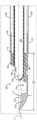
现在转到图2C,示出了棒远端120的横截面,轴100可以包括围绕管状构件242同轴设置的管状外轴250。外轴250可以是导电的并且提供返回电极112和连接器234之间的电连通。外轴250可以用电绝缘材料251涂覆或覆盖以在返回电极112和手柄204之间具有非导电外表面。返回电极112可以从护套251的最远端延伸到远侧尖端。返回电极112限定导电材料的暴露部分并且相对于有源电极104进一步向近侧和向远侧轴向延伸。有源电极104大体上由电极112围绕或至少部分地由电极环绕。返回电极112具有与轴250连续的近侧管状部分,限定用于在其中接收管状构件242和有源电极104的管腔。返回电极112可以终止于具有远侧前缘117的提升器尖端113,所述远侧前缘构造成机械地刺穿鼻甲组织以将有源电极104放置在鼻甲内。远侧前缘117可以限定围绕尖端113的顶部平台118的连续弯曲边缘。提升器尖端113可以电联接到返回电极112或形成返回电极的一部分,但是能量可能不需要或优选最初刺穿鼻甲组织。提升器尖端113构造成具有足够的刚性以提升和刺穿组织,因此限定在有源电极104远侧的较厚部分(T)。前缘117可以基本上沿着与棒纵向轴线L-L重合的平面终止。远侧前缘117与双侧边缘121连续,所述双侧边缘主要从前缘117轴向地和近侧地延伸并且可以具有相对于沿其的纵向轴线(L_L)的最小凹曲率。双侧边缘121的一部分还可以包括构造成有助于分离组织以接近鼻甲的边缘。这允许作为可操作以提供双极电外科效果的工作部件的部件与组织可操作地连通,部件包括有源电极104、流体输送孔和流体/碎屑去除孔。尖端还包括凸弧形表面119,所述凸弧形表面随着尖端向远侧延伸而朝向纵向轴线弯曲,从而在刺穿鼻甲期间提供滑动表面。表面119可限定凸面并限定装置的纵向轴线的凸侧。刺穿鼻甲至少部分是盲过程,并且用户刺穿鼻甲,然后可以将前缘117放置在相对于鼻甲位于中间的骨上。将远端120进一步滑入鼻甲中并同时将前缘117保持在骨表面上可以最佳地将有源电极104放置在鼻甲的中间。Turning now to FIG. 2C , showing a cross-section of the rod
在图5中示出了替代的棒远端提升器尖端实施例520。尖端513可以限定延伸曲线构造,使得前缘517可以与在纵向轴线L-L的与有源电极104相同的一侧上的平面P重合(从图5的视图中看不到)并且比至少图2B和2C中所示的前缘117从纵向轴线L-L径向间隔开更远。在该替代实施例中,远侧前缘517与双侧边缘521连续,所述双侧边缘从前缘517向近侧延伸并且可以具有相对于沿其的纵向轴线(L_L)的曲率或角取向。双侧边缘521可以相对于纵向轴线沿着角α延伸,该角限定钝角。在一些优选取向中,该角可以在115-150度之间。前缘517可以设置成比有源电极104径向离纵向轴线更远。在一些实施例中,前缘517可以设置成比外轴250的上外表面250a离纵向轴线更远。前缘517可以位于平面P上,所述平面从纵向轴线升高距离E1并且从上外表面521升高距离E2。远端还可以包括从最远侧边缘517沿着主要纵向轴线向近侧延伸的内弧形表面,弧形表面具有限定凹方向的凹表面,并且在凸弧形表面518的相对侧上。第一和第二弧形边缘可以限定弧形表面的侧向边缘521。An alternative rod distal
延伸尖端构造513可以提供多种优点。例如,尖端513可以形成面向远侧的弯曲表面518,所述面向远侧的弯曲表面用作犁,引导由穿刺尖端513释放的组织远离吸入孔245。在刺穿鼻甲时,可以通过穿刺尖端对鼻甲组织的部分进行机械取芯或释放。具有如图5或图8A所示的延伸弯曲表面518的尖端与其他实施例中所示的弯曲表面119相比可以更多地阻挡或重定向这些松散的鼻甲组织部分远离孔245。弯曲构造延伸得越多,可以重定向越多的组织,从而可以逐渐减少吸入导管240的堵塞。The
与边缘117相似的前缘517构造成在使用期间接合并沿着鼻甲620内的鼻甲骨跟踪,在图6A和6B中最佳地示出。鼻甲骨650提供参考表面,原因是治疗通常在没有直接可视化的情况下进行。一般而言,尖端113或513构造成将有源电极104放置成远离鼻甲骨650并且更居中地位于鼻甲620内。附加的接触表面由点A处的外表面限定,所述外表面可以是间隔件150或轴100的外表面。使骨与尖端前缘117或517以及点A两者接合可以将有源电极放置在优选位置,即鼻甲内的中心。或者说,有源电极104与延伸通过点A和前缘517或117两者的交线B-B间隔开。对于更延伸的弯曲构造,例如尖端513,有源电极104可以与鼻甲骨650间隔得更远。延伸的尖端曲率可以将有源电极104放置在鼻甲620内更中心的位置。随着尖端曲率的增加,入口切口的切口扩张660可能相关地减小,如图6A和6B中所示。图6A示出了具有如本文所公开的尖端113的第一棒远端实施例120。图6B示出了具有延伸曲率构造的第二棒远端实施例520。在两个图6A和6B中,前缘117和517与鼻甲骨650接合并且可以在对鼻甲组织620进行电外科治疗时沿着鼻甲骨650向后和向前(显示为位置1和位置2)平移。切口660可以在该平移期间扩张以适应治疗期间棒的运动。优选的是边缘(117、517)在移动和缩减鼻甲的同时保持与骨的接触。在一些方法中,还优选的是点“A”在移动和缩减鼻甲时保持接触。这将有源电极的目标位置保持在鼻甲的中间并与骨605间隔开。比较图6A和6B可以看出,诸如尖端113的尖端可能需要比图6A和6B所示的更侵进的尖端513更大的切口扩张660a。对于位置1和2之间的相同平移,切口扩张660b比切口扩张660a更小且更优选。Leading
现在回到图2C,返回电极112限定腔116以在其中接收陶瓷间隔件150和有源电极104,以便将返回电极112的部分定位成与有源电极104相邻但不接触。返回电极112优选地以这样的方式设置,使得对于尽可能多的有源电极104轮廓,在有源电极104和围绕有源电极的返回电极边缘之间保持接近均匀距离。通过在有源电极和返回电极之间保持基本一致且较小的距离,电源28可能需要较低的能量或电压来产生所需的组织效应,并且组织效应越局部化,产生越受控的组织效应,这对外科医生来说是可取的。这可以最大限度地减少预期区域之外的不需要的组织治疗。在所示的实施例中,有源电极和返回电极之间的距离可以在大约0.2mm至1.5mm之间,并且实施例可以优选为大约0.8mm。Returning now to FIG. 2C ,
如图2C和2D中最佳所示,有源电极104嵌套在电绝缘间隔件150内。间隔件150可以是管状的,其内径尺寸确定成接收管状构件242的远端并由此接收有源电极104。有源电极104限定如先前公开的导电管242的暴露部分,导电管242限定吸入导管240。间隔件远侧开口成形为包绕并限定导电管242的暴露部分并由此限定有源电极104。导电管242和间隔件150固定联接并且不相对于彼此或相对于外轴250和返回电极112旋转。间隔件150不仅是电绝缘的,而且还构造成最小限度地随等离子体降解,并且可以由陶瓷材料形成。间隔件150的一部分伸缩到返回电极112中(见图2C)。有源电极104可以具有圆形或球状的最远端105,其中吸入孔245与端部105近侧间隔开。吸入孔245尺寸确定成增加组织去除并且可以围绕管242的侧面周向延伸并且轴向延伸以与间隔件开口的近侧边缘重合(参见图2E)。孔245可以是非圆形的,或者轴向延伸比周向延伸更长。孔245可以侧向设置并且限定大致垂直于轴纵向轴线的中心轴线。孔245也可以尺寸确定成能够插入清除堵塞工具。棒远端120大体上是光滑的并且成角以提供到目标组织的良好通路。As best shown in FIGS. 2C and 2D , the
转到图2F,示出了远端120的侧视图,所述远端包括可以与纵向轴线L-L重合的前缘117。还示出了通过点A和前缘117的交线B-B,有源电极104与线B-B在内侧间隔开。如前所述,这允许将有源电极104优选地放置在鼻甲组织内,使用参考表面A和前缘117两者作为与鼻甲骨的接触点。如图2F中所示,具有较不剧烈弯曲的尖端可以提供有源电极104与骨的优选间隔。Turning to Figure 2F, a side view of the
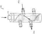
现在参考图2G、2H和2I,本公开现在将描述用于将导电流体供应到与有源电极104相邻的区域的流体输送导管和路径。用于该装置的冲洗可以在手柄和远端120之间在管状构件242(其具有电绝缘外表面)和外轴250的内管腔之间的环形横截面中进行。在远端处,冲洗可以通过陶瓷间隔件150和返回电极管状部分之间的环形开口,如图2H和图2I中最佳所示。在该实施例中,流体出口200A位于间隔件150的顶部上并且双侧(2)流体出口200B位于间隔件150的侧面上。在一些实施例中,可以通过穿过外管250形成的任何开口添加其他出口。Referring now to FIGS. 2G , 2H, and 2I, the present disclosure will now describe fluid delivery conduits and pathways for supplying conductive fluid to the region adjacent to
在远端120处,冲洗流体在陶瓷间隔件150的外表面和返回电极112的内表面之间形成的小环形间隙之间轴向流动,间隙由第一肋170形成。肋170可以形成为陶瓷间隔件150、返回电极112的一部分或可以是单独的部件。如图所示,肋170限定近端,所述近端是轴向延伸并平行于纵向轴线的单个肋170,其可以侧向地围绕有源电极104的每一侧双侧地和基本均等地分配流体输送。单个出口200a与肋170重合,单个出口200a具有比肋宽度更大的直径以允许一些流体流出出口200a。肋170或支座可以在刚好在出口200a远侧直至并包括间隔件150的最远端的位置处双侧和周向膨胀,以便将流动沿周向和围绕朝向有源电极104的侧面引导。肋170的较大部分还可以提供更大的表面积以用于将返回电极112粘合剂联接和流体密封到间隔件150,限制流体进入间隔件150下方。间隔件150成形为形成出口200b和200c的至少两个双侧对。出口200b形成在侧向间隔边缘和双侧边缘121之间以将流体供应到有源电极104的侧面。出口200c构造成提供朝向有源电极104的远侧球状部分以远侧取向流动的流体。流体输送出口200a、200b和200c大体上构造成从多个方向围绕有源电极并充分润湿有源电极并桥接返回电极112和有源电极104之间的电连接。流体输送出口200a、200b和200c大体上构造成引导流体围绕尖端并且优选不围绕间隔件150的最远端,原因是这可能在返回电极112和有源电极104之间产生虚拟电极和/或分流电路径。优选多个流体输送出口200a、200b和200c以继续提供导电流体,即使出口中的一个被堵塞。流体输送出口200b和200c大体上围绕有源电极104的侧向部分。At the
优选电极表面均匀润湿以在有源电极104和返回电极112之间产生更均匀的电场,从而产生更可靠和均匀的组织效应。相对干燥并且可能会引起电阻加热效应和不希望的组织效应的返回外部表面的区域是那些区域。流体输送可以被控制以便仅在能量被输送到棒远端140时才输送流体,并且可以可通信地联接到控制器以便在施加能量的同时自动输送流体。单独的控制或方法可以进一步包括在用导电流体刺穿鼻甲时对形成的鼻甲腔进行灌注。灌注可以改善电极润湿,并且可以通过例如棒手柄上的按钮单独控制。It is preferred that the electrode surface be uniformly wetted to create a more uniform electric field between the
因此设想了一种缩减鼻甲的方法,其包括将电外科棒远端放置到鼻腔中和选择的鼻甲内,使用提升器尖端(113、513、813)的非钝远侧前缘首先刺穿鼻甲620,然后进一步将远端推进到鼻甲620中。提升器尖端的前缘117、517可以接触并沿着鼻腔的骨质部分650滑动,同时将棒的远端推进到鼻甲中。这可以在不使用电外科能量的情况下实现。如果在推进棒时需要组织凝固,则可以选择性地施加能量。然后可以将棒的有源电极104直接定位在要去除的鼻甲的一部分附近。提升器尖端113、513可以构造成将有源电极104在鼻甲620内居中放置,同时边缘(117、517、817)接合鼻甲骨650。更具体地,在最小限度的直接观察的情况下,前缘(117、517、817)和与有源电极104近侧间隔开的第二参考表面A两者都可以接合鼻甲骨,从而将有源电极104放置在鼻甲内的目标位置。然后可以将导电流体输送到棒远端以预灌注鼻甲腔,导电流体通过沿着棒的流体供应导管输送。导管可以是沿着棒轴的环形导管。导管可以至少部分地由肋170限定,所述肋围绕电极间隔件的外表面双侧地分开流体并分流到与有源电极相邻的多个流体出口。肋可以是接合轴的内表面的棒的间隔件150的外表面的一体部分。肋170朝向肋远端周向地延伸以从彼此平衡的多个流体输送孔输送流体。可以启动真空源,真空源通过棒手柄和有源电极孔245与孔225流体连通。然后可以启动电源28(图1中所示)以减少邻近有源电极104的鼻甲组织620的体积。导电流体提供有源电极104和返回电极112之间的传导路径。该方法可以包括选择性地覆盖手柄孔225以增加有源电极孔245处的吸入压力,从而去除流体、等离子体副产物和组织碎屑。孔225可以被部分覆盖或完全覆盖以改变消融和组织凝固之间的平衡,同时将能量输送到棒远端。仅当施加能量时才可以覆盖孔225以限制可能引起吸入管腔堵塞的意外组织抽吸。可以平移和/或旋转棒90以消融目标鼻甲620的组织块并由此对其减体积。可以平移棒90,同时保持边缘117、517与鼻甲骨650接合。在平移棒的同时,从边缘(117、517)延伸的面向远侧的凸弯曲表面可以引导松散的组织远离孔245,从而减少孔堵塞。此外,由于泵40提供的流体压力,提供到鼻腔中的导电流体可以具有扩大开口以接近和治疗目标鼻组织的效果。在进入的腔组织内提供的压力下,流体的作用是扩大开口并在腔组织内提供额外的空间,从而允许在有源电极104处形成有效的等离子体。输送的流体速率可以由泵40控制,或者替代地使用阀(未示出)控制,使得组织和电极间隔件150之间的区域不断地浸没或涂有流体并且返回电极112被充分润湿。A method of turbinate reduction is therefore envisaged comprising placing the distal end of an electrosurgical wand into the nasal cavity and into a selected turbinate, first piercing the turbinate using the non-blunt distal leading edge of the lifter tip (113, 513, 813) 620, the distal end is then further advanced into the turbinate 620. The
取决于手术,外科医生可以相对于鼻甲组织旋转和/或平移电极104以在鼻甲内形成孔、通道、条纹、凹口、凹坑等。此外,外科医生可能会故意将电源调节为凝固模式以治疗切断的血管或在这些孔或通道内产生一些热损伤以形成将在手术后抑制鼻甲肿胀的疤痕组织。Depending on the procedure, the surgeon may rotate and/or translate the
在示例性系统中,用户可以选择将控制器的射频发生器输出设置为预设输出能量水平的能量输出“模式”,每个模式与期望的组织缩减与目标组织的相互作用相关,例如减体积或加热,或血管凝固。控制器28还可以控制流体输送到棒远端(120、520、720、820)的速率,以及可选择的能量输出,并且某些组织模式或用户做出的选择可以触发某些预设流体流速以进一步改善组织效应。In an exemplary system, the user may choose to set the controller's RF generator output to a preset output energy level of energy output "modes", each mode associated with a desired tissue reduction interaction with the target tissue, eg, volume reduction Or heating, or blood vessel coagulation. The controller 28 may also control the rate of fluid delivery to the distal end of the wand (120, 520, 720, 820), as well as selectable energy output, and certain tissue patterns or user-made selections may trigger certain preset fluid flow rates to further improve the organizational effect.
例如,如果用户希望高速率的组织减体积并且发生器可以提供足以形成等离子体并以高速率去除组织的能量,控制器可以具有高模式。控制器还可以具有可以提供中等速率的组织减体积的中等模式,或替代地提供混合模式,所述混合模式可以提供伴随一些止血的消融。这可以启动射频发生器28的脉冲,其中射频发生器在提供足以形成等离子体的能量和然后降低电压以使等离子体塌缩之间进行调制,其中脉冲在等离子体形成时提供初始加热效果和一些止血。这可能会以比高模式下更低的速率缩减组织体积,并同时提供一些组织收缩和出血控制。如前所述,可以通过脉冲工作循环的切割和止血周期之间的相应比率来实现不同程度的减体积和止血。每个模式选择还可以改变向组织620和棒远端120、520的流体输送。当优选热加热时,外科医生可以选择低模式,其中使用较低电压对组织进行热治疗。间歇性高压脉冲可以去除电极附近的组织。当遇到较大的血管或一些出血时,在不需要消融的情况下可以选择凝固模式。与消融和混合模式相比,在低模式期间流体输送可以自动减少。For example, if the user desires a high rate of tissue debulking and the generator can provide sufficient energy to form a plasma and remove tissue at a high rate, the controller may have a high mode. The controller may also have an intermediate mode that can provide a moderate rate of tissue de-volume, or alternatively provide a hybrid mode that can provide ablation with some hemostasis. This can initiate pulsing of the RF generator 28, where the RF generator modulates between providing sufficient energy to form the plasma and then reducing the voltage to collapse the plasma, where the pulse provides an initial heating effect and some Stop bleeding. This may reduce tissue volume at a lower rate than in high mode, while providing some tissue shrinkage and hemorrhage control. As previously discussed, varying degrees of volume reduction and hemostasis can be achieved by corresponding ratios between the cutting and hemostasis cycles of the pulsed duty cycle. Each mode selection may also alter the fluid delivery to the
在一些方法中,当组织被体积去除以在鼻甲中形成通常具有小于3mm、优选小于2mm的直径的一个或多个孔时,医生在鼻甲组织内轴向旋转轴远侧部分120、520。此外,可以控制由电源28输送的电压,使得引导到目标部位的能量不足以消融骨或脂肪组织(其通常具有比目标窦组织更高的阻抗)。以该方式,外科医生可以确实地从骨清除组织,而不会消融或以其他方式对骨造成重大损伤。In some methods, the physician axially rotates the shaft
图3A和3B示出了可选的切换阀300或吸入反向阀,其可以帮助去除吸入导管内的堵塞物。切换阀与流体输送和抽吸管流体连通,并且可以设置在手柄壳体内并且沿着管道在近侧与手柄204间隔开。可以切换该阀300以关闭吸入并沿着吸入导管向下推动冲洗。在操作中,致动器310可以例如逐渐平移以减小从装置顶部到阀的距离,从而逐渐增加流动反向的速度。在其他实施例中,肘节阀300可以与螺线管接合,或者也可以锁定就位(类似于点击圆珠笔)。Figures 3A and 3B illustrate an
有源电极104可以具有光滑的球状或圆形端部105,因此可能不容易沿其形成等离子体(或至少与孔245处的边缘一样容易)。图4A-4C示出了替代的远端实施例420,其具有与图2A-2I中公开的实施例相似的部件,除了有源电极405可以具有更正交的面向远侧的表面410。表面410可以通过分裂和使吸入管440的端部处的两个臂朝向彼此弯曲并横跨吸入管直径的大部分而形成。吸入管440可以类似于管状构件242。因而,面向远侧的表面410可以包括两个边缘表面411,所述边缘表面可以彼此邻接或稍微间隔开;使得两个边缘表面411可以提供可以更自然地沿其形成高电流密度并因此更容易沿其形成等离子体的表面粗糙。因此,这可以提供比例如图2A-2C中所示的实施例的圆形或球形端部更宽和更强的消融率。面向远侧的表面构造成提供屏障并限制组织滑入孔445,同时获得到鼻甲组织的通路。The
此外,远端实施例420可以包括具有与孔245类似的位置和功能的孔445。然而,孔445进一步侧向延伸到边缘并一直延伸到吸入管440的端部处的两个臂。因此孔445更大,从而允许更多的碎屑清除和更小的堵塞可能性。Additionally,
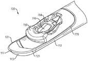
用于缩减鼻甲的另一棒实施例在图7A-7F中公开。相同的部件标有相同的附图标记。提升器尖端113限定非钝远侧边缘117以刺穿鼻甲组织,并且可以包括面向远侧的凸面119,所述凸面被成形为引导或犁开松散的组织远离有源电极704和孔745。面向远侧的凸面119可以限定轴的凸方向或凸侧。前缘117可以围绕限定弧形表面的侧向边缘的第一和第二弧形边缘121延伸并限定第一和第二弧形边缘。轴还可以限定导管开口770,所述导管开口在近侧与最远侧边缘间隔开并且在凸侧的相对侧上。Another rod embodiment for reducing turbinates is disclosed in Figures 7A-7F. Identical parts are marked with the same reference numerals.
开口770可以将绝缘间隔件750和电极704嵌套在其中。电极治疗表面705可以与纵向轴线成角θ定向。角θ可以通过棒远端打开并且范围在100-150度之间。在该实施例中,有源电极704可以限定部分或完整的环或环形元件,所述环或环形元件限定通过其中的单个孔745。环形有源电极704限定孔边界的至少一部分,并且如图所示,孔745可以限定完全由电极704界定的360度界定孔。此外如图2E中所示,电极704限定最大环腿宽度W1,通过其中的单个孔具有最大宽度W2,宽度W2显著大于环腿宽度W1。例如,W2可能比W1大至少50%。在一些示例性实施例中,W2可以是W1的至少两倍。在一些另外的示例性实施例中,W2可以是W1的至少三倍。孔宽度W2可以在0.030-0.040英寸之间,而W1可以在.005-.010英寸之间。具有大孔可以减少组织堵塞,并在需要时允许使用清除堵塞工具。Opening 770 may nest insulating
如图7C中最佳所示,提升器尖端113的最远侧边缘117可以与纵向轴线重合。在一些其他实施例中,最远侧边缘117可以进一步远离凸侧延伸,以与平行于纵向轴线并远离轴的凸侧偏移的平面重合。最远侧边缘117和间隔件750上的点A沿着参考线B-B限定两个点,所述点构造成限定有源电极704相对于鼻甲骨的位置。如前所述,优选的是有源电极705与该整条线在内侧间隔开,该线指示鼻甲骨的表面。As best shown in Figure 7C, the
如图7D中最佳所示,示出了远端720的横截面,间隔件750可以包括远侧脊752。类似于凸面119,脊752可以像犁一样起作用并且使松散的组织块偏离有源电极孔745。这可以有助于避免堵塞孔745和相关的抽吸结构。脊752限定在源电极704远侧的间隔件750的突出部分,并且与有源电极704部分重叠。脊752的外表面可以比孔745的远侧部分更远离轴的纵向轴线延伸。脊752可以构造成使棒远端720的侧面周围的组织偏转,如图7E中的箭头F所示。As best shown in FIG. 7D , showing a cross-section of the
也如图7D中所示,轴可以容纳包括管760或细长导管的流体抽吸构造。管760可以在远端处与孔745和由间隔件限定的导管754流体连通,并且在近端处经由管道42与另一端处的负压源(未示出)流体连通。管760可以由聚合物形成,并且可以具有比导管754和孔745更大的内径或横截面。根据至少一些实施例,孔745的组合可以在有源电极704附近产生收缩(并且因此产生等离子体)。由孔745和近侧布置的孔(754、760)之间的相互作用产生的收缩示出了在示例性系统中实施的操作原理。该原理依赖于将组织分成小到足以通过孔745所呈现的收缩的块。孔754和760的孔或横截面尺寸在孔745后面打开或变宽,因此如果组织可以适合通过孔745,组织很可能穿过整个抽吸结构或路径而不会堵塞。As also shown in Figure 7D, the shaft can accommodate a fluid suction configuration comprising a
通过示例性有源电极704的孔745的横截面积有助于操作原理。特别地,孔745的横截面积可以优选地小于间隔件孔754和管内径。因此,一块组织只需要在任何两个维度上都足够小以适合通过孔745,然后当组织移动通过抽吸路径时将只遇到更大的横截面积。根据示例性系统,孔745和孔754、760之间的横截面积差异可以在百分之一(1%)至百分之三十(30%)之间,并且在特定情况下为至少百分之二十(20%)。管760可以沿着轴延伸并通过手柄,如早先的图中所示。The principle of operation is facilitated by the cross-sectional area of the
在该实施例中,有源电极704可以使用例如电缆707电联接。此外,导电流体780可以沿着轴输送到远端720。轴可以限定流体输送结构的一部分,使得导管是由外轴的内表面和管760的外表面界定的环形间隙。流体780可以经由轴向邻近有源电极704、通过轴的下侧的孔785输送到远端720的外表面。流体也可以通过流体联接到环形间隙的孔786输送。In this embodiment, the
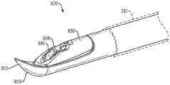
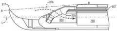
电外科装置远端820的另一实施例在图8A-8D中被公开以用于治疗鼻甲。与先前公开的实施例类似,远端820包括具有凸面819、间隔件850和电极804的提升器尖端813。有源电极804可以通过电缆807电联接到电外科发生器。在该示例性实施例中,有源电极804和间隔件850被定向成使得进入轴的流体抽吸路径876遵循比与图7A-7F中的实施例相关联的流动路径756更不曲折的路线。更直射且方向改变较少的流体抽吸路径允许一致的流体抽吸体积,从而可以减少堵塞。更具体地,该实施例限定比图7D中所示实施例的路径更接近于平行于纵向轴线L的流体吸入路径。简而言之,该吸入路径需要较少的方向改变。这允许流体沿着流体流动路径更有效地移动碎屑。然而,这可能倾向于允许更多松散的组织颗粒进入孔845,因此更延伸的提升器尖端813构造可能更优选以重定向一些碎屑/松散组织。提升器尖端构造可以进一步围绕装置远端820延伸,使得最远侧边缘817与平行且偏离纵向轴线的平面重合。Another embodiment of an electrosurgical device
该实施例还可以包括具有突起805的有源电极804,所述突起延伸到孔845的近端上的孔845中。突起805构造成中断孔845并局部减小有效孔尺寸。该减小的孔尺寸可以减少堵塞。如前所述,已发现从入口孔845到管道760的直径逐渐增加的导管尺寸可以帮助减少堵塞。因此,突起局部减小了入口孔845的开口尺寸,使得通过间隔件850的导管854的开口尺寸略大于入口孔845,并且管760的管腔直径大于导管854。突起805的外表面也可以用作清除堵塞工具的滑动表面,所述清除堵塞工具可以插入到抽吸结构中并沿着抽吸结构插入以保护抽吸结构的上部分。This embodiment may also include an
尽管仅描述了本发明的几个实施例,但应当理解,在不脱离本发明的精神或范围的情况下,本发明可以以许多其他具体形式实施。因此,本示例被认为是说明性的而不是限制性的,并且本发明不限于这里给出的细节,而是可以在所附权利要求的范围内进行修改。Although only a few embodiments of the present invention have been described, it should be understood that the present invention may be embodied in many other specific forms without departing from the spirit or scope of the invention. Therefore, the present examples are to be regarded as illustrative rather than restrictive, and the invention is not limited to the details given herein, but may be modified within the scope of the appended claims.
Claims (20)
Priority Applications (1)
| Application Number | Priority Date | Filing Date | Title |
|---|---|---|---|
| CN202410286134.8ACN118453103A (en) | 2019-12-19 | 2020-12-17 | System and method for turbinate reduction |
Applications Claiming Priority (3)
| Application Number | Priority Date | Filing Date | Title |
|---|---|---|---|
| US201962950632P | 2019-12-19 | 2019-12-19 | |
| US62/950,632 | 2019-12-19 | ||
| PCT/US2020/065527WO2021127125A1 (en) | 2019-12-19 | 2020-12-17 | Systems and methods for turbinate reduction |
Related Child Applications (1)
| Application Number | Title | Priority Date | Filing Date |
|---|---|---|---|
| CN202410286134.8ADivisionCN118453103A (en) | 2019-12-19 | 2020-12-17 | System and method for turbinate reduction |
Publications (2)
| Publication Number | Publication Date |
|---|---|
| CN114786607Atrue CN114786607A (en) | 2022-07-22 |
| CN114786607B CN114786607B (en) | 2024-03-29 |
Family
ID=74186878
Family Applications (2)
| Application Number | Title | Priority Date | Filing Date |
|---|---|---|---|
| CN202080086309.0AActiveCN114786607B (en) | 2019-12-19 | 2020-12-17 | Systems and methods for turbinate reduction |
| CN202410286134.8APendingCN118453103A (en) | 2019-12-19 | 2020-12-17 | System and method for turbinate reduction |
Family Applications After (1)
| Application Number | Title | Priority Date | Filing Date |
|---|---|---|---|
| CN202410286134.8APendingCN118453103A (en) | 2019-12-19 | 2020-12-17 | System and method for turbinate reduction |
Country Status (5)
| Country | Link |
|---|---|
| US (1) | US20230045026A1 (en) |
| EP (1) | EP4065022B1 (en) |
| CN (2) | CN114786607B (en) |
| AU (1) | AU2020408344B2 (en) |
| WO (1) | WO2021127125A1 (en) |
Cited By (1)
| Publication number | Priority date | Publication date | Assignee | Title |
|---|---|---|---|---|
| CN118903583A (en)* | 2024-10-10 | 2024-11-08 | 浙江工业大学 | Auxiliary suction structure of cooling medium liquid |
Families Citing this family (1)
| Publication number | Priority date | Publication date | Assignee | Title |
|---|---|---|---|---|
| EP4558071A1 (en)* | 2022-08-25 | 2025-05-28 | Arthrex, Inc. | Ablation probe and lumen for improved access and flow |
Citations (6)
| Publication number | Priority date | Publication date | Assignee | Title |
|---|---|---|---|---|
| US20050251190A1 (en)* | 2000-05-16 | 2005-11-10 | Mcfarlane Richard H | Penetrating tip for trocar assembly |
| US20140100557A1 (en)* | 2012-10-05 | 2014-04-10 | Medtronic Advanced Energy Llc | Electrosurgical device for cutting and removing tissue |
| US20140200581A1 (en)* | 2013-01-17 | 2014-07-17 | Arthrocare Corporation | Systems and methods for turbinate reduction |
| CN104546124A (en)* | 2013-10-15 | 2015-04-29 | 佳乐医疗设备有限公司 | Electrosurgical electrode and instrument |
| CN107438411A (en)* | 2015-02-18 | 2017-12-05 | 美敦力施美德公司 | The tissue wound-cleaning device realized by RF energy |
| CN110603000A (en)* | 2017-05-16 | 2019-12-20 | 史密夫和内修有限公司 | Electrosurgical system and method |
Family Cites Families (11)
| Publication number | Priority date | Publication date | Assignee | Title |
|---|---|---|---|---|
| US5697882A (en) | 1992-01-07 | 1997-12-16 | Arthrocare Corporation | System and method for electrosurgical cutting and ablation |
| US6355032B1 (en) | 1995-06-07 | 2002-03-12 | Arthrocare Corporation | Systems and methods for selective electrosurgical treatment of body structures |
| US6142992A (en) | 1993-05-10 | 2000-11-07 | Arthrocare Corporation | Power supply for limiting power in electrosurgery |
| US6235020B1 (en) | 1993-05-10 | 2001-05-22 | Arthrocare Corporation | Power supply and methods for fluid delivery in electrosurgery |
| US6149120A (en) | 1997-03-27 | 2000-11-21 | Hall; Donald M. | Low profile slidable shelf |
| FR2780953B1 (en) | 1998-07-09 | 2000-09-29 | Itw De France | SHUTTER FOR AN OPENING MADE IN A SHEET |
| EP1437977B1 (en)* | 2001-10-02 | 2014-05-21 | ArthroCare Corporation | Apparatus for electrosurgical removal and digestion of tissue |
| US6749608B2 (en)* | 2002-08-05 | 2004-06-15 | Jon C. Garito | Adenoid curette electrosurgical probe |
| US7879034B2 (en)* | 2006-03-02 | 2011-02-01 | Arthrocare Corporation | Internally located return electrode electrosurgical apparatus, system and method |
| US8747401B2 (en)* | 2011-01-20 | 2014-06-10 | Arthrocare Corporation | Systems and methods for turbinate reduction |
| JP7125472B2 (en)* | 2017-04-10 | 2022-08-24 | スミス アンド ネフュー インコーポレイテッド | Plasma surgical device |
- 2020
- 2020-12-17EPEP20842417.6Apatent/EP4065022B1/enactiveActive
- 2020-12-17CNCN202080086309.0Apatent/CN114786607B/enactiveActive
- 2020-12-17WOPCT/US2020/065527patent/WO2021127125A1/ennot_activeCeased
- 2020-12-17CNCN202410286134.8Apatent/CN118453103A/enactivePending
- 2020-12-17AUAU2020408344Apatent/AU2020408344B2/enactiveActive
- 2020-12-17USUS17/786,246patent/US20230045026A1/enactivePending
Patent Citations (6)
| Publication number | Priority date | Publication date | Assignee | Title |
|---|---|---|---|---|
| US20050251190A1 (en)* | 2000-05-16 | 2005-11-10 | Mcfarlane Richard H | Penetrating tip for trocar assembly |
| US20140100557A1 (en)* | 2012-10-05 | 2014-04-10 | Medtronic Advanced Energy Llc | Electrosurgical device for cutting and removing tissue |
| US20140200581A1 (en)* | 2013-01-17 | 2014-07-17 | Arthrocare Corporation | Systems and methods for turbinate reduction |
| CN104546124A (en)* | 2013-10-15 | 2015-04-29 | 佳乐医疗设备有限公司 | Electrosurgical electrode and instrument |
| CN107438411A (en)* | 2015-02-18 | 2017-12-05 | 美敦力施美德公司 | The tissue wound-cleaning device realized by RF energy |
| CN110603000A (en)* | 2017-05-16 | 2019-12-20 | 史密夫和内修有限公司 | Electrosurgical system and method |
Cited By (1)
| Publication number | Priority date | Publication date | Assignee | Title |
|---|---|---|---|---|
| CN118903583A (en)* | 2024-10-10 | 2024-11-08 | 浙江工业大学 | Auxiliary suction structure of cooling medium liquid |
Also Published As
| Publication number | Publication date |
|---|---|
| EP4065022A1 (en) | 2022-10-05 |
| CN118453103A (en) | 2024-08-09 |
| CN114786607B (en) | 2024-03-29 |
| WO2021127125A1 (en) | 2021-06-24 |
| AU2020408344A1 (en) | 2022-06-09 |
| EP4065022B1 (en) | 2023-05-10 |
| US20230045026A1 (en) | 2023-02-09 |
| AU2020408344B2 (en) | 2023-08-03 |
Similar Documents
| Publication | Publication Date | Title |
|---|---|---|
| CN110603000B (en) | Electrosurgical system and method | |
| US9649144B2 (en) | Systems and methods for turbinate reduction | |
| US8747401B2 (en) | Systems and methods for turbinate reduction | |
| CN113329709B (en) | Combined electrosurgical and mechanical resecting device | |
| US8137345B2 (en) | Electrosurgical devices for tonsillectomy and adenoidectomy | |
| US8979842B2 (en) | Wire electrode devices for tonsillectomy and adenoidectomy | |
| US7491200B2 (en) | Method for treating obstructive sleep disorder includes removing tissue from base of tongue | |
| US7090672B2 (en) | Method for treating obstructive sleep disorder includes removing tissue from the base of tongue | |
| US20060036237A1 (en) | Devices and methods for selective orientation of electrosurgical devices | |
| KR20170117440A (en) | Tissue ablation devices that can use RF energy | |
| US20200188014A1 (en) | Electrosurgical systems and methods | |
| CN114786607B (en) | Systems and methods for turbinate reduction | |
| CN119095545A (en) | Electrosurgical laryngeal stick |
Legal Events
| Date | Code | Title | Description |
|---|---|---|---|
| PB01 | Publication | ||
| PB01 | Publication | ||
| SE01 | Entry into force of request for substantive examination | ||
| SE01 | Entry into force of request for substantive examination | ||
| GR01 | Patent grant | ||
| GR01 | Patent grant |