CN114785279A - Integrated device of photovoltaic panel thermoelectric power generation and temperature control based on semiconductor thermoelectric effect - Google Patents
Integrated device of photovoltaic panel thermoelectric power generation and temperature control based on semiconductor thermoelectric effectDownload PDFInfo
- Publication number
- CN114785279A CN114785279ACN202210623919.0ACN202210623919ACN114785279ACN 114785279 ACN114785279 ACN 114785279ACN 202210623919 ACN202210623919 ACN 202210623919ACN 114785279 ACN114785279 ACN 114785279A
- Authority
- CN
- China
- Prior art keywords
- semiconductor
- photovoltaic panel
- module
- thermoelectric
- electrically connected
- Prior art date
- Legal status (The legal status is an assumption and is not a legal conclusion. Google has not performed a legal analysis and makes no representation as to the accuracy of the status listed.)
- Pending
Links
Images


Classifications
- H—ELECTRICITY
- H02—GENERATION; CONVERSION OR DISTRIBUTION OF ELECTRIC POWER
- H02S—GENERATION OF ELECTRIC POWER BY CONVERSION OF INFRARED RADIATION, VISIBLE LIGHT OR ULTRAVIOLET LIGHT, e.g. USING PHOTOVOLTAIC [PV] MODULES
- H02S40/00—Components or accessories in combination with PV modules, not provided for in groups H02S10/00 - H02S30/00
- H02S40/40—Thermal components
- H02S40/42—Cooling means
- F—MECHANICAL ENGINEERING; LIGHTING; HEATING; WEAPONS; BLASTING
- F25—REFRIGERATION OR COOLING; COMBINED HEATING AND REFRIGERATION SYSTEMS; HEAT PUMP SYSTEMS; MANUFACTURE OR STORAGE OF ICE; LIQUEFACTION SOLIDIFICATION OF GASES
- F25B—REFRIGERATION MACHINES, PLANTS OR SYSTEMS; COMBINED HEATING AND REFRIGERATION SYSTEMS; HEAT PUMP SYSTEMS
- F25B21/00—Machines, plants or systems, using electric or magnetic effects
- F25B21/02—Machines, plants or systems, using electric or magnetic effects using Peltier effect; using Nernst-Ettinghausen effect
- H—ELECTRICITY
- H02—GENERATION; CONVERSION OR DISTRIBUTION OF ELECTRIC POWER
- H02N—ELECTRIC MACHINES NOT OTHERWISE PROVIDED FOR
- H02N11/00—Generators or motors not provided for elsewhere; Alleged perpetua mobilia obtained by electric or magnetic means
- H02N11/002—Generators
- H—ELECTRICITY
- H02—GENERATION; CONVERSION OR DISTRIBUTION OF ELECTRIC POWER
- H02S—GENERATION OF ELECTRIC POWER BY CONVERSION OF INFRARED RADIATION, VISIBLE LIGHT OR ULTRAVIOLET LIGHT, e.g. USING PHOTOVOLTAIC [PV] MODULES
- H02S30/00—Structural details of PV modules other than those related to light conversion
- H—ELECTRICITY
- H02—GENERATION; CONVERSION OR DISTRIBUTION OF ELECTRIC POWER
- H02S—GENERATION OF ELECTRIC POWER BY CONVERSION OF INFRARED RADIATION, VISIBLE LIGHT OR ULTRAVIOLET LIGHT, e.g. USING PHOTOVOLTAIC [PV] MODULES
- H02S40/00—Components or accessories in combination with PV modules, not provided for in groups H02S10/00 - H02S30/00
- H02S40/30—Electrical components
- H02S40/38—Energy storage means, e.g. batteries, structurally associated with PV modules
Landscapes
- Engineering & Computer Science (AREA)
- Physics & Mathematics (AREA)
- Mechanical Engineering (AREA)
- Thermal Sciences (AREA)
- General Engineering & Computer Science (AREA)
- Photovoltaic Devices (AREA)
Abstract
Description
Translated fromChinese技术领域technical field
本发明涉及太阳能光伏、温差发电和半导体制冷领域,更具体地说,涉及基于半导体热电效应的光伏板温差发电及温控一体化装置。The invention relates to the fields of solar photovoltaic, thermoelectric power generation and semiconductor refrigeration, and more particularly, to an integrated device for thermoelectric power generation and temperature control of photovoltaic panels based on the thermoelectric effect of semiconductors.
背景技术Background technique
随着社会的急速发展,对能源的需求也急剧增加,为实现“碳达峰”和“碳中和”等目标,国家对可再生能源的研究十分重视,与传统能源相比,太阳能具有储量丰富、清洁、可再生等优点,利用太阳能发电更加节能环保,且无噪音,对解决我国能源问题有着极大的作用。With the rapid development of society, the demand for energy has also increased sharply. In order to achieve the goals of "carbon peaking" and "carbon neutrality", the country attaches great importance to the research of renewable energy. Compared with traditional energy, solar energy has reserves Rich, clean, renewable and other advantages, the use of solar power generation is more energy-saving and environmentally friendly, and has no noise, which plays a great role in solving my country's energy problems.
目前光伏板的效率随温度的升高而降低,因此,为了进一步提高光伏板发电效率,重点在于研发新型光伏板散热技术,现有光伏板散热技术包括风冷,液冷,半导体温差发电/制冷技术等,但目前由于光伏板背部的余热,在风冷和液冷技术中大多数被耗散掉,未能进行有效的利用;而半导体温差发电技术不仅能够吸收利用光伏板背面的废热发出额外电能,还能在一定程度上降低光伏板背板温度并提高光伏板发电效率;其次,半导体制冷技术通过输入电能以显著降低光伏板背板温度从而提高光伏板发电效率,但现有技术无法准确控制在何时,在什么温度条件下启动制冷开关,以最大化装置光伏板和温差半导体模块的整体发电效率;现有技术中,目前还没有一种能够基于光伏板实时温度条件的,可在温差发电和制冷两种模式之间切换的光伏一体化装置。At present, the efficiency of photovoltaic panels decreases with the increase of temperature. Therefore, in order to further improve the power generation efficiency of photovoltaic panels, the focus is on developing new heat dissipation technologies for photovoltaic panels. Existing heat dissipation technologies for photovoltaic panels include air cooling, liquid cooling, and semiconductor thermoelectric power generation/cooling. However, due to the waste heat on the back of photovoltaic panels, most of them are dissipated in air-cooled and liquid-cooled technologies and cannot be used effectively; and semiconductor thermoelectric power generation technology can not only absorb and utilize the waste heat on the back of photovoltaic panels to emit additional heat Electric energy can also reduce the temperature of the back panel of the photovoltaic panel and improve the power generation efficiency of the photovoltaic panel to a certain extent; secondly, the semiconductor refrigeration technology can significantly reduce the temperature of the photovoltaic panel back panel by inputting electric energy, thereby improving the power generation efficiency of the photovoltaic panel, but the existing technology cannot accurately Control when and under what temperature conditions the refrigeration switch is activated to maximize the overall power generation efficiency of the photovoltaic panels and thermoelectric semiconductor modules; A photovoltaic integrated device that switches between thermoelectric power generation and cooling modes.
发明内容SUMMARY OF THE INVENTION
1.要解决的技术问题1. Technical problems to be solved
针对现有技术中存在的问题,本发明的目的在于提供基于半导体热电效应的光伏板温差发电及温控一体化装置,本方案可以实现根据温度传感器的数据和光照强度传感器的数据,分别预测出每一个模式下光伏板和半导体模块的整体输出功率,并同时求出在发电模式和制冷模式之间切换的临界温度T0,当光伏板温度超过临界温度T0时,半导体模块切换至制冷模式;当光伏板温度低于临界温度T0时,半导体模块切换至发电模式,通过在TEG、TEC模式之间的动态切换,保证光伏板运行在合适的温度区间,同时,在发电模式下,能够利用TEG对废热进行利用发电,提高效率。In view of the problems existing in the prior art, the purpose of the present invention is to provide an integrated device for thermoelectric power generation and temperature control of photovoltaic panels based on the thermoelectric effect of semiconductors. This solution can realize the prediction of the data according to the data of the temperature sensor and the data of the light intensity sensor, respectively. The overall output power of the photovoltaic panel and the semiconductor module in each mode, and the critical temperature T0 for switching between the power generation mode and the cooling mode is obtained at the same time. When the photovoltaic panel temperature exceeds the critical temperature T0, the semiconductor module switches to the cooling mode; when When the temperature of the photovoltaic panel is lower than the critical temperature T0, the semiconductor module switches to the power generation mode. Through the dynamic switching between TEG and TEC modes, the photovoltaic panel is guaranteed to run in a suitable temperature range. At the same time, in the power generation mode, the TEG can be used to The waste heat is used to generate electricity and improve the efficiency.
2.技术方案2. Technical solutions
为解决上述问题,本发明采用如下的技术方案。In order to solve the above problems, the present invention adopts the following technical solutions.
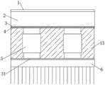
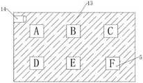
基于半导体热电效应的光伏板温差发电及温控一体化装置,包括透明玻璃盖板,所述透明玻璃盖板下端安装有光伏板,所述光伏板下端涂设有导热硅脂Ⅰ,所述导热硅脂Ⅰ内部安装有温度传感器,所述导热硅脂Ⅰ下端安装有多个均匀分布的半导体模块,所述半导体模块下端安装有翅片散热模块,所述半导体模块与翅片散热模块内壁之间设有导热硅脂Ⅱ,多个所述半导体模块外端填充隔热保温材料,所述隔热保温材料位于导热硅脂Ⅰ和翅片散热模块内壁之间,所述透明玻璃盖板上端固定安装有光照强度传感器,所述光伏板的外端电性连接有电池模块,所述半导体模块与电池模块之间电性连接,所述电池模块外端电性连接有模式切换模块。An integrated device for thermoelectric power generation and temperature control of photovoltaic panels based on the thermoelectric effect of semiconductors, including a transparent glass cover plate, a photovoltaic panel is installed at the lower end of the transparent glass cover plate, and thermally conductive silicone grease I is coated on the lower end of the photovoltaic panel. A temperature sensor is installed inside the silicone grease I, a plurality of evenly distributed semiconductor modules are installed at the lower end of the thermal conductive silicone grease I, a fin heat dissipation module is installed at the lower end of the semiconductor module, and the semiconductor module and the inner wall of the fin heat dissipation module are installed Heat-conducting silicone grease II is provided, and the outer ends of a plurality of the semiconductor modules are filled with heat-insulating materials. The heat-insulating materials are located between the heat-conducting grease I and the inner wall of the fin heat dissipation module, and the transparent glass cover is fixedly installed at the upper end. There is a light intensity sensor, a battery module is electrically connected to the outer end of the photovoltaic panel, the semiconductor module is electrically connected to the battery module, and a mode switching module is electrically connected to the outer end of the battery module.
进一步的,所述模式切换模块由一个包含支路一、支路二的并联电路组成,所述支路一包括电池模块外端电性连接的二极管Ⅰ,所述二极管Ⅰ外端电性连接有切换开关,所述切换开关外端电性连接有制冷模式指示灯,所述制冷模式指示灯与多个半导体模块之间电性连接,所述支路二包括电池模块外端电性连接的二极管Ⅱ,所述二极管Ⅱ外端电性连接有切换开关,所述切换开关外端电性连接有发电模式指示灯,所述发电模式指示灯与多个半导体模块之间电性连接。Further, the mode switching module is composed of a parallel circuit including branch 1 and
进一步的,多个所述半导体模块之间为并联连接,且由切换开关、二极管Ⅰ、二极管Ⅱ、制冷模式指示灯和发电模式指示灯统一控制。Further, a plurality of the semiconductor modules are connected in parallel, and are uniformly controlled by a switch, diode I, diode II, a cooling mode indicator light and a power generation mode indicator light.
进一步的,所述透明玻璃盖板为高透射率的亚克力玻璃平板制成,且厚度为2mm。Further, the transparent glass cover plate is made of a high transmittance acrylic glass flat plate, and the thickness is 2 mm.
进一步的,所述半导体模块为半导体制冷片,且分为正反两面,印字一面朝上,与光伏板背面相连接,无印字一面朝下,所述半导体模块左端设有红线,所述半导体模块右端设有黑线。Further, the semiconductor module is a semiconductor refrigerating sheet, and is divided into two sides, the printed side faces up, and is connected to the back of the photovoltaic panel, and the non-printed side faces down. The left end of the semiconductor module is provided with a red line, and the There is a black line on the right end of the semiconductor module.
进一步的,所述光伏板的正接线柱与电池模块的正极连接,所述光伏板的负接线柱与电池模块的负极连接,所述半导体模块右端黑线与电池模块7的负极相连。Further, the positive terminal of the photovoltaic panel is connected to the positive terminal of the battery module, the negative terminal of the photovoltaic panel is connected to the negative terminal of the battery module, and the black line at the right end of the semiconductor module is connected to the negative terminal of the
进一步的,所述电池模块为可重复充放电电池箱,所述电池模块内设有逆变器。Further, the battery module is a rechargeable and dischargeable battery box, and the battery module is provided with an inverter.
进一步的,所述温度传感器由热电偶和输出电路组成。Further, the temperature sensor is composed of a thermocouple and an output circuit.
进一步的,所述光照强度传感器由太阳功率计或辐射计和输出电路组成,且受光面朝上。Further, the light intensity sensor is composed of a solar power meter or a radiometer and an output circuit, and the light-receiving surface faces upward.
进一步的,所示模式切换模块由逻辑电路组成,所述温度传感器和光照强度传感器读取的数据分别通过线路接入切换开关内。Further, the mode switching module shown is composed of a logic circuit, and the data read by the temperature sensor and the light intensity sensor are respectively connected into the switching switch through lines.
3.有益效果3. Beneficial effects
相比于现有技术,本发明的优点在于:Compared with the prior art, the advantages of the present invention are:
(1)本方案提出的模式切换开关模块,能极大程度的提升装置整体的发电效率,在光伏板温度过高时,半导体模块能够切换至制冷模式,将光伏板的温度控制在其最佳发电效率区间;在光伏板温度低于临界温度T0时,半导体模块切换至发电模式,充分利用光伏板的废热发电,从而最大化提高整体的发电效率。(1) The mode switching switch module proposed in this scheme can greatly improve the overall power generation efficiency of the device. When the temperature of the photovoltaic panel is too high, the semiconductor module can switch to the cooling mode to control the temperature of the photovoltaic panel at its optimum Power generation efficiency range: When the temperature of the photovoltaic panel is lower than the critical temperature T0, the semiconductor module switches to the power generation mode, making full use of the waste heat of the photovoltaic panel to generate power, thereby maximizing the overall power generation efficiency.
(2)本方案中的模式切换开关可以实现自动切换,无需手动操作,大大提高操作的简便性。(2) The mode switching switch in this scheme can realize automatic switching without manual operation, which greatly improves the convenience of operation.
(3)本方案仅需在光伏板下方增加少量空间即可实现发电效率的增加,不会增加光伏板原有的占地面积,减少占用空间。(3) This scheme only needs to add a small amount of space under the photovoltaic panel to increase the power generation efficiency, without increasing the original area of the photovoltaic panel and reducing the occupied space.
附图说明Description of drawings
图1为本发明基于半导体热电效应的光伏板温差发电及温控一体化装置总体结构的示意图;1 is a schematic diagram of the overall structure of the photovoltaic panel thermoelectric power generation and temperature control integrated device based on the semiconductor thermoelectric effect of the present invention;
图2为本发明半导体发电制冷片模式切换的控制电路图;Fig. 2 is the control circuit diagram of the mode switching of the semiconductor power generation refrigeration chip of the present invention;
图3为本发明图1中的侧视结构示意图;Fig. 3 is the side view structure schematic diagram in Fig. 1 of the present invention;
图4为本发明图1中的俯视结构示意图;Fig. 4 is the top view structure schematic diagram in Fig. 1 of the present invention;
图5为本发明光伏板为电池模块充电时的工作电路图;FIG. 5 is a working circuit diagram of the photovoltaic panel of the present invention when charging the battery module;
图6为本发明半导体模块制冷模式的工作电路图;Fig. 6 is the working circuit diagram of the cooling mode of the semiconductor module of the present invention;
图7为本发明半导体模块发电模式的工作电路图;7 is a working circuit diagram of the semiconductor module power generation mode of the present invention;
图8为本发明模式切换开关包含的设计逻辑示意图。FIG. 8 is a schematic diagram of the design logic included in the mode switch of the present invention.
图中标号说明:Description of the labels in the figure:
1透明玻璃盖板、2光伏板、3导热硅脂Ⅰ、31导热硅脂Ⅱ、4温度传感器、5半导体模块、6翅片散热模块、7电池模块、8切换开关、9二极管Ⅰ、10二极管Ⅱ、11制冷模式指示灯、12发电模式指示灯、13隔热保温材料、14光照强度传感器。1 transparent glass cover, 2 photovoltaic panels, 3 thermal grease I, 31 thermal grease II, 4 temperature sensor, 5 semiconductor module, 6 fin heat dissipation module, 7 battery module, 8 switch, 9 diode I, 10 diode Ⅱ, 11 cooling mode indicator light, 12 power generation mode indicator light, 13 thermal insulation material, 14 light intensity sensor.
具体实施方式Detailed ways
下面将结合本发明实施例中的附图;对本发明实施例中的技术方案进行清楚、完整地描述;显然;所描述的实施例仅仅是本发明一部分实施例;而不是全部的实施例,基于本发明中的实施例;本领域普通技术人员在没有做出创造性劳动前提下所获得的所有其他实施例;都属于本发明保护的范围。The following will combine the drawings in the embodiments of the present invention; clearly and completely describe the technical solutions in the embodiments of the present invention; obviously; the described embodiments are only a part of the embodiments of the present invention; rather than all the embodiments, based on The embodiments of the present invention; all other embodiments obtained by those of ordinary skill in the art without creative work; all belong to the protection scope of the present invention.
在本发明的描述中,需要说明的是,术语“上”、“下”、“内”、“外”、“顶/底端”等指示的方位或位置关系为基于附图所示的方位或位置关系,仅是为了便于描述本发明和简化描述,而不是指示或暗示所指的装置或元件必须具有特定的方位、以特定的方位构造和操作,因此不能理解为对本发明的限制。此外,术语“第一”、“第二”仅用于描述目的,而不能理解为指示或暗示相对重要性。In the description of the present invention, it should be noted that the orientations or positional relationships indicated by the terms "upper", "lower", "inner", "outer", "top/bottom", etc. are based on the orientations shown in the accompanying drawings Or the positional relationship is only for the convenience of describing the present invention and simplifying the description, rather than indicating or implying that the indicated device or element must have a specific orientation, be constructed and operated in a specific orientation, and therefore should not be construed as a limitation of the present invention. Furthermore, the terms "first" and "second" are used for descriptive purposes only and should not be construed to indicate or imply relative importance.
在本发明的描述中,需要说明的是,除非另有明确的规定和限定,术语“安装”、“设置有”、“套设/接”、“连接”等,应做广义理解,例如“连接”,可以是固定连接,也可以是可拆卸连接,或一体地连接;可以是机械连接,也可以是电连接;可以是直接相连,也可以通过中间媒介间接相连,可以是两个元件内部的连通。对于本领域的普通技术人员而言,可以具体情况理解上述术语在本发明中的具体含义。In the description of the present invention, it should be noted that, unless otherwise expressly specified and limited, the terms "installation", "provided with", "sleeve/connection", "connection", etc., should be understood in a broad sense, such as " "connection", which can be a fixed connection, a detachable connection, or an integral connection; it can be a mechanical connection or an electrical connection; it can be directly connected, or indirectly connected through an intermediate medium, and it can be an internal connection between two components. of connectivity. For those of ordinary skill in the art, the specific meanings of the above terms in the present invention can be understood in specific situations.
实施例1:Example 1:
请参阅图1-8,基于半导体热电效应的光伏板温差发电及温控一体化装置,包括透明玻璃盖板1,透明玻璃盖板1下端安装有光伏板2,光伏板2下端涂设有导热硅脂Ⅰ3,导热硅脂Ⅰ3内部安装有温度传感器4,导热硅脂Ⅰ3下端安装有多个均匀分布的半导体模块5,半导体模块5下端安装有翅片散热模块6,半导体模块5与翅片散热模块6内壁之间设有导热硅脂Ⅱ31,多个半导体模块5外端填充隔热保温材料13,隔热保温材料13位于导热硅脂Ⅰ3和翅片散热模块6内壁之间,透明玻璃盖板1上端固定安装有光照强度传感器14,光伏板2的外端电性连接有电池模块7,半导体模块5与电池模块7之间电性连接,电池模块7外端电性连接有模式切换模块。Please refer to Figure 1-8. The photovoltaic panel thermoelectric power generation and temperature control integrated device based on the thermoelectric effect of semiconductors includes a transparent glass cover plate 1, a
请参阅图1-7,模式切换模块由一个包含支路一、支路二的并联电路组成,支路一包括电池模块7外端电性连接的二极管Ⅰ9,二极管Ⅰ9外端电性连接有切换开关8,切换开关8外端电性连接有制冷模式指示灯11,制冷模式指示灯11与多个半导体模块5之间电性连接,支路二包括电池模块7外端电性连接的二极管Ⅱ10,二极管Ⅱ10外端电性连接有切换开关8,切换开关8外端电性连接有发电模式指示灯12,发电模式指示灯12与多个半导体模块5之间电性连接。Please refer to Figure 1-7. The mode switching module consists of a parallel circuit including branch 1 and
请参阅图1-7,多个半导体模块5之间为并联连接,且由切换开关8、二极管Ⅰ9、二极管Ⅱ10、制冷模式指示灯11和发电模式指示灯12统一控制。Referring to FIGS. 1-7 , a plurality of
请参阅图1-3,透明玻璃盖板1为高透射率的亚克力玻璃平板制成,且厚度为2mm,透明玻璃盖板1紧密附着在光伏板2的正面,防止光伏板2受灰尘附着或雨水的影响,降低外在因素对发电效率的影响。Please refer to Figure 1-3, the transparent glass cover plate 1 is made of a high transmittance acrylic glass flat plate with a thickness of 2mm. The transparent glass cover plate 1 is closely attached to the front of the
请参阅图3-4,半导体模块5为半导体制冷片,且分为正反两面,印字一面朝上,与光伏板2背面相连接,无印字一面朝下,半导体模块5左端设有红线,半导体模块5右端设有黑线,当红线与电池模块7正极相连,黑线与电池模块7负极相连,则半导体模块5印字一面制冷,无印字一面发热;当黑线与电池模块7正极相连,红线与电池模块7负极相连,则半导体模块5印字一面利用废热发电,此时半导体模块5为电源充电。Please refer to Fig. 3-4, the
请参阅图1-2,光伏板2的正接线柱与电池模块7的正极连接,光伏板2的负接线柱与电池模块7的负极连接,半导体模块5右端黑线与电池模块7的负极相连。Please refer to Figure 1-2, the positive terminal of the
请参阅图1-2,电池模块7为可重复充放电电池箱,电池模块7内设有逆变器,能够调节输入的电流大小。Please refer to Fig. 1-2. The
请参阅图1-3,温度传感器4由热电偶和输出电路组成,温度传感器4仅安装在编号5B的半导体模块5与光伏板2之间,埋在温度传感器4中,其余的半导体模块5上方均未安装热电偶。Please refer to Figure 1-3, the
请参阅图1-4,光照强度传感器14由太阳功率计或辐射计和输出电路组成,且受光面朝上。Referring to Figures 1-4, the
请参阅图1-7,所示模式切换模块由逻辑电路组成,温度传感器4和光照强度传感器14读取的数据分别通过线路接入切换开关8内。1-7, the mode switching module shown is composed of a logic circuit, and the data read by the
本方案根据温度传感器4数据和光照强度传感器14的数据,分别预测出每一个模式下光伏板2和半导体模块5的整体输出功率并求出在发电模式和制冷模式之间切换的临界温度T0,当光伏板2温度超过临界温度T0,半导体模块5切换至制冷模式;当光伏板2温度低于临界温度T0,半导体模块5切换至发电模式;通过TEG/TEC模式的动态切换,保证光伏板2运行在合适的温度区间,同时,在发电模式下,能够利用TEG对废热进行利用发电,提高效率。According to the data of the
实施例2:Example 2:
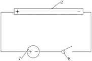
当太阳光透过透明盖板1照射在光伏板2上,光伏板2产生的电流通过电线流向电池模块7,并为电池模块7充电,其工作电路如图5所示。When sunlight shines on the
当模式切换模块读取到温度传感器4内热电偶探测的光伏板温度超出临界温度T0时,则模式切换模块将使支路一中的二极管Ⅰ9、切换开关8、制冷模式指示灯11保持通路,使支路二中的二极管Ⅱ10、切换开关8、发电模式指示灯12断开,具体工作电路如图6所示。When the mode switching module reads that the temperature of the photovoltaic panel detected by the thermocouple in the
当模式切换模块8读取到温度传感器4内热电偶探测的光伏板温度低于临界温度T0时,则模式切换模块将使支路一中的二极管Ⅰ9、切换开关8、制冷模式指示灯11断开,使支路二中的二极管Ⅱ10、切换开关8、发电模式指示灯12保持通路,具体工作电路如图7所示。When the
以上所述;仅为本发明较佳的具体实施方式;但本发明的保护范围并不局限于此;任何熟悉本技术领域的技术人员在本发明揭露的技术范围内;根据本发明的技术方案及其改进构思加以等同替换或改变;都应涵盖在本发明的保护范围内。The above is only a preferred embodiment of the present invention; but the protection scope of the present invention is not limited to this; any person skilled in the art is within the technical scope disclosed by the present invention; according to the technical solution of the present invention equivalent replacements or changes to its improved ideas; all should be covered within the protection scope of the present invention.
Claims (10)
Priority Applications (1)
| Application Number | Priority Date | Filing Date | Title |
|---|---|---|---|
| CN202210623919.0ACN114785279A (en) | 2022-06-02 | 2022-06-02 | Integrated device of photovoltaic panel thermoelectric power generation and temperature control based on semiconductor thermoelectric effect |
Applications Claiming Priority (1)
| Application Number | Priority Date | Filing Date | Title |
|---|---|---|---|
| CN202210623919.0ACN114785279A (en) | 2022-06-02 | 2022-06-02 | Integrated device of photovoltaic panel thermoelectric power generation and temperature control based on semiconductor thermoelectric effect |
Publications (1)
| Publication Number | Publication Date |
|---|---|
| CN114785279Atrue CN114785279A (en) | 2022-07-22 |
Family
ID=82421301
Family Applications (1)
| Application Number | Title | Priority Date | Filing Date |
|---|---|---|---|
| CN202210623919.0APendingCN114785279A (en) | 2022-06-02 | 2022-06-02 | Integrated device of photovoltaic panel thermoelectric power generation and temperature control based on semiconductor thermoelectric effect |
Country Status (1)
| Country | Link |
|---|---|
| CN (1) | CN114785279A (en) |
Citations (8)
| Publication number | Priority date | Publication date | Assignee | Title |
|---|---|---|---|---|
| CN101806514A (en)* | 2010-03-10 | 2010-08-18 | 中国科学技术大学 | Composite solar photovoltaic hot-water cold supply and heating system for building |
| CN102647122A (en)* | 2012-05-15 | 2012-08-22 | 上海电力学院 | Solar photovoltaic-temperature difference automatic temperature control combined power generation device |
| KR20130087902A (en)* | 2012-01-30 | 2013-08-07 | 주식회사 케이디파워 | Monitoring control apparatus of pv system |
| CN104331103A (en)* | 2014-10-29 | 2015-02-04 | 苏州佑瑞检测技术有限公司 | Semiconductor temperature control system applied to greenhouse |
| CN205070938U (en)* | 2015-10-15 | 2016-03-02 | 江门职业技术学院 | Thermoelectric generation system based on solar cell panel |
| CN111682832A (en)* | 2020-05-19 | 2020-09-18 | 江苏大学 | A photovoltaic thermoelectric combined power generation device based on micro heat pipe plate and W-shaped fins |
| CN112737079A (en)* | 2020-12-29 | 2021-04-30 | 山西大学 | Photovoltaic and semiconductor temperature difference combined power generation system |
| CN114400970A (en)* | 2022-02-10 | 2022-04-26 | 香港中文大学(深圳) | Solar power generation device combining photovoltaic-phase change heat storage-semiconductor power generation and refrigeration |
- 2022
- 2022-06-02CNCN202210623919.0Apatent/CN114785279A/enactivePending
Patent Citations (8)
| Publication number | Priority date | Publication date | Assignee | Title |
|---|---|---|---|---|
| CN101806514A (en)* | 2010-03-10 | 2010-08-18 | 中国科学技术大学 | Composite solar photovoltaic hot-water cold supply and heating system for building |
| KR20130087902A (en)* | 2012-01-30 | 2013-08-07 | 주식회사 케이디파워 | Monitoring control apparatus of pv system |
| CN102647122A (en)* | 2012-05-15 | 2012-08-22 | 上海电力学院 | Solar photovoltaic-temperature difference automatic temperature control combined power generation device |
| CN104331103A (en)* | 2014-10-29 | 2015-02-04 | 苏州佑瑞检测技术有限公司 | Semiconductor temperature control system applied to greenhouse |
| CN205070938U (en)* | 2015-10-15 | 2016-03-02 | 江门职业技术学院 | Thermoelectric generation system based on solar cell panel |
| CN111682832A (en)* | 2020-05-19 | 2020-09-18 | 江苏大学 | A photovoltaic thermoelectric combined power generation device based on micro heat pipe plate and W-shaped fins |
| CN112737079A (en)* | 2020-12-29 | 2021-04-30 | 山西大学 | Photovoltaic and semiconductor temperature difference combined power generation system |
| CN114400970A (en)* | 2022-02-10 | 2022-04-26 | 香港中文大学(深圳) | Solar power generation device combining photovoltaic-phase change heat storage-semiconductor power generation and refrigeration |
Similar Documents
| Publication | Publication Date | Title |
|---|---|---|
| CN101769460A (en) | Light emitting diode lamp | |
| KR100923509B1 (en) | Self-powered lighting device and street lamp using the same | |
| CN101619842A (en) | Light-emitting diode lamp and light engine thereof | |
| TW201043845A (en) | Solar energy street lamp structure with air inlet | |
| CN101644398B (en) | LED lighting device with fast energy storage and heat dissipation | |
| CN103532439A (en) | Dual-form thermoelectric power generation device | |
| CN101463956B (en) | Wind power combined water-refrigeration LED road lamp | |
| CN114400970A (en) | Solar power generation device combining photovoltaic-phase change heat storage-semiconductor power generation and refrigeration | |
| KR102599542B1 (en) | Lighting device using combined power generation | |
| CN210111882U (en) | Thermoelectric generator based on household appliance waste heat utilization | |
| CN103527955A (en) | LED illuminating system with heat recovering function | |
| CN217563613U (en) | Photovoltaic panel thermoelectric generation and temperature control integrated device based on semiconductor thermoelectric effect | |
| CN212377908U (en) | Integrated street lamp with double-cavity lamp holder | |
| CN102723899A (en) | Electric appliance possessing thermoelectric convertor | |
| CN114785279A (en) | Integrated device of photovoltaic panel thermoelectric power generation and temperature control based on semiconductor thermoelectric effect | |
| CN215259573U (en) | Energy-saving street lighting | |
| CN210007948U (en) | Power supply device and lighting system for LED lamps | |
| CN216873158U (en) | Solar power generation device combining photovoltaic-phase change heat storage-semiconductor power generation and refrigeration | |
| CN106090808A (en) | A kind of high efficiency thermoelectric conversion LED lamp | |
| CN106304488A (en) | A kind of based on the road lamp system measuring flow of the people | |
| CN201766530U (en) | Focused water-cooled heat dissipation solar power generation device | |
| CN101907261A (en) | Solar street lamp structure with air flow channel | |
| CN113669679B (en) | Energy-saving control method of lighting street lamp with monitoring function | |
| CN206430036U (en) | A kind of integrated solar power generation lamp holder | |
| CN211830617U (en) | Temperature difference power generation device for street lamp |
Legal Events
| Date | Code | Title | Description |
|---|---|---|---|
| PB01 | Publication | ||
| PB01 | Publication | ||
| SE01 | Entry into force of request for substantive examination | ||
| SE01 | Entry into force of request for substantive examination | ||
| CB03 | Change of inventor or designer information | Inventor after:Ji Dongxu Inventor after:Peng Dingxiang Inventor after:Tan Hui Inventor after:Ling Fan Inventor after:Yin Wenbin Inventor after:Zhang Yalong Inventor before:Ji Dongxu Inventor before:Zhang Yaqi Inventor before:Tan Hui Inventor before:Ling Fan Inventor before:Yin Wenbin Inventor before:Zhang Yalong | |
| CB03 | Change of inventor or designer information |