CN114785168B - Maximum Power Tracking Method for Inductive Energy Harvesting System Based on Impedance Matching - Google Patents
Maximum Power Tracking Method for Inductive Energy Harvesting System Based on Impedance MatchingDownload PDFInfo
- Publication number
- CN114785168B CN114785168BCN202210501972.3ACN202210501972ACN114785168BCN 114785168 BCN114785168 BCN 114785168BCN 202210501972 ACN202210501972 ACN 202210501972ACN 114785168 BCN114785168 BCN 114785168B
- Authority
- CN
- China
- Prior art keywords
- energy harvesting
- maximum power
- inductive energy
- mos transistor
- semi
- Prior art date
- Legal status (The legal status is an assumption and is not a legal conclusion. Google has not performed a legal analysis and makes no representation as to the accuracy of the status listed.)
- Active
Links
Images

Classifications
- H—ELECTRICITY
- H02—GENERATION; CONVERSION OR DISTRIBUTION OF ELECTRIC POWER
- H02M—APPARATUS FOR CONVERSION BETWEEN AC AND AC, BETWEEN AC AND DC, OR BETWEEN DC AND DC, AND FOR USE WITH MAINS OR SIMILAR POWER SUPPLY SYSTEMS; CONVERSION OF DC OR AC INPUT POWER INTO SURGE OUTPUT POWER; CONTROL OR REGULATION THEREOF
- H02M7/00—Conversion of AC power input into DC power output; Conversion of DC power input into AC power output
- H02M7/02—Conversion of AC power input into DC power output without possibility of reversal
- H02M7/04—Conversion of AC power input into DC power output without possibility of reversal by static converters
- H02M7/12—Conversion of AC power input into DC power output without possibility of reversal by static converters using discharge tubes with control electrode or semiconductor devices with control electrode
- H02M7/21—Conversion of AC power input into DC power output without possibility of reversal by static converters using discharge tubes with control electrode or semiconductor devices with control electrode using devices of a triode or transistor type requiring continuous application of a control signal
- H02M7/217—Conversion of AC power input into DC power output without possibility of reversal by static converters using discharge tubes with control electrode or semiconductor devices with control electrode using devices of a triode or transistor type requiring continuous application of a control signal using semiconductor devices only
- H02M7/219—Conversion of AC power input into DC power output without possibility of reversal by static converters using discharge tubes with control electrode or semiconductor devices with control electrode using devices of a triode or transistor type requiring continuous application of a control signal using semiconductor devices only in a bridge configuration
- H—ELECTRICITY
- H02—GENERATION; CONVERSION OR DISTRIBUTION OF ELECTRIC POWER
- H02J—CIRCUIT ARRANGEMENTS OR SYSTEMS FOR SUPPLYING OR DISTRIBUTING ELECTRIC POWER; SYSTEMS FOR STORING ELECTRIC ENERGY
- H02J50/00—Circuit arrangements or systems for wireless supply or distribution of electric power
- H02J50/001—Energy harvesting or scavenging
- H—ELECTRICITY
- H02—GENERATION; CONVERSION OR DISTRIBUTION OF ELECTRIC POWER
- H02M—APPARATUS FOR CONVERSION BETWEEN AC AND AC, BETWEEN AC AND DC, OR BETWEEN DC AND DC, AND FOR USE WITH MAINS OR SIMILAR POWER SUPPLY SYSTEMS; CONVERSION OF DC OR AC INPUT POWER INTO SURGE OUTPUT POWER; CONTROL OR REGULATION THEREOF
- H02M1/00—Details of apparatus for conversion
- H02M1/08—Circuits specially adapted for the generation of control voltages for semiconductor devices incorporated in static converters
- H—ELECTRICITY
- H02—GENERATION; CONVERSION OR DISTRIBUTION OF ELECTRIC POWER
- H02M—APPARATUS FOR CONVERSION BETWEEN AC AND AC, BETWEEN AC AND DC, OR BETWEEN DC AND DC, AND FOR USE WITH MAINS OR SIMILAR POWER SUPPLY SYSTEMS; CONVERSION OF DC OR AC INPUT POWER INTO SURGE OUTPUT POWER; CONTROL OR REGULATION THEREOF
- H02M1/00—Details of apparatus for conversion
- H02M1/42—Circuits or arrangements for compensating for or adjusting power factor in converters or inverters
- H02M1/4208—Arrangements for improving power factor of AC input
- H02M1/4233—Arrangements for improving power factor of AC input using a bridge converter comprising active switches
- Y—GENERAL TAGGING OF NEW TECHNOLOGICAL DEVELOPMENTS; GENERAL TAGGING OF CROSS-SECTIONAL TECHNOLOGIES SPANNING OVER SEVERAL SECTIONS OF THE IPC; TECHNICAL SUBJECTS COVERED BY FORMER USPC CROSS-REFERENCE ART COLLECTIONS [XRACs] AND DIGESTS
- Y02—TECHNOLOGIES OR APPLICATIONS FOR MITIGATION OR ADAPTATION AGAINST CLIMATE CHANGE
- Y02B—CLIMATE CHANGE MITIGATION TECHNOLOGIES RELATED TO BUILDINGS, e.g. HOUSING, HOUSE APPLIANCES OR RELATED END-USER APPLICATIONS
- Y02B70/00—Technologies for an efficient end-user side electric power management and consumption
- Y02B70/10—Technologies improving the efficiency by using switched-mode power supplies [SMPS], i.e. efficient power electronics conversion e.g. power factor correction or reduction of losses in power supplies or efficient standby modes
Landscapes
- Engineering & Computer Science (AREA)
- Power Engineering (AREA)
- Computer Networks & Wireless Communication (AREA)
- Control Of Electrical Variables (AREA)
Abstract
Translated fromChinese
Description
Translated fromChinese技术领域technical field
本发明涉及感应取能技术,具体涉及一种基于阻抗匹配的感应能量收集系统最大功率追踪方法。The invention relates to inductive energy harvesting technology, in particular to a maximum power tracking method for an inductive energy harvesting system based on impedance matching.
背景技术Background technique
近年来,智能电网(Smart Grid,SG)一直在高速发展,以整合具有高供电可靠性的可再生能源。为保证SG的正常运行,常常通过无线传感器网络(Wireless Sensor Network,WSN)有效监控电器和电力线路的运行状态。WSN本身作为SG的关键基础设施,往往需要持续稳定的电源来实现。In recent years, Smart Grid (SG) has been developing at a high speed to integrate renewable energy with high power supply reliability. In order to ensure the normal operation of SG, the operating status of electrical appliances and power lines is often effectively monitored through a wireless sensor network (WSN). As the key infrastructure of SG, WSN itself often requires continuous and stable power supply to realize.
传统意义上,电池被用作传感器网络节点的电源。然而,它们的容量有限,并且相对昂贵且不方便,特别是需要定期更换和维护。因此,非常需要具有自供电功能的WSN来克服上述缺点。能量收集(Energy Harvesting,EH)技术为传感器自供电提供了绝佳机会,能量收集是指从周围环境中收集固有能量,如太阳能、风能、振动能、电场能、磁场能等,然后将其转化为电能,给传感节点提供持续稳定的电能供给。由于磁能量收集(MagneticEnergy Harvesting,MEH)技术具有高功率密度,高供电可靠性,低成本,体积小等特点,被广泛应用在输电线路传感设备自供电领域。Batteries have traditionally been used as power sources for sensor network nodes. However, they have limited capacity and are relatively expensive and inconvenient, especially requiring regular replacement and maintenance. Therefore, there is a great need for WSNs with self-powered functions to overcome the above disadvantages. Energy harvesting (Energy Harvesting, EH) technology provides an excellent opportunity for self-powered sensors. Energy harvesting refers to the collection of inherent energy from the surrounding environment, such as solar energy, wind energy, vibration energy, electric field energy, magnetic field energy, etc., and then transforms it into For electrical energy, provide continuous and stable electrical energy supply to sensor nodes. Because Magnetic Energy Harvesting (MEH) technology has the characteristics of high power density, high power supply reliability, low cost, and small size, it is widely used in the field of self-power supply for transmission line sensing equipment.
目前的感应能量收集系统中,常常通过增加磁芯体积来达到功率提升的目的,这种往往会增加输电系统的负担,加大系统运行的风险。In the current inductive energy harvesting system, the power increase is often achieved by increasing the volume of the magnetic core, which often increases the burden on the power transmission system and increases the risk of system operation.
发明内容Contents of the invention
基于上述问题,本发明的目的在于提出一种基于阻抗匹配的感应能量收集系统最大功率追踪方法,该方法能在不考虑非线性磁饱和特性对系统内阻抗的影响情况下,通过阻抗匹配的思路,利用半有源整流电路通过移相控制的方法对系统等效输出外阻抗进行调节,使内外阻抗实现匹配,在不同应用场景下精确实现最优移相角的控制,提升系统能量传输功率。Based on the above problems, the purpose of the present invention is to propose a maximum power tracking method for inductive energy harvesting systems based on impedance matching. , use the semi-active rectifier circuit to adjust the equivalent output external impedance of the system through the method of phase shift control, so that the internal and external impedance can be matched, and the control of the optimal phase shift angle can be accurately realized in different application scenarios, and the energy transmission power of the system can be improved.
为了实现上述目的,本发明所采用的具体技术方案如下:In order to achieve the above object, the specific technical scheme adopted in the present invention is as follows:
一种基于阻抗匹配的感应能量收集系统最大功率追踪方法,其关键在于,包括以下步骤:A maximum power tracking method for an inductive energy harvesting system based on impedance matching, the key of which is to include the following steps:
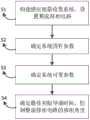
S1:构建感应能量收集系统模型,在感应取能单元和负载之间设置半有源整流电路;S1: Construct the model of the inductive energy harvesting system, and set up a semi-active rectification circuit between the inductive energy harvesting unit and the load;
S2:确定感应取能单元的磁芯截面积A、饱和磁感应强度Bsat、感应线圈绕组匝数N以及系统工作角频率ω;S2: Determine the cross-sectional area A of the magnetic core of the induction energy harvesting unit, the saturation magnetic induction Bsat , the number of turns N of the induction coil winding, and the operating angular frequency ω of the system;
S3:获取负载电阻值RL和感应取能单元的感应电流,并确定感应电流有效值Is;S3: Obtain the load resistance valueRL and the induction current of the induction energy-taking unit, and determine the effective value Is of the induction current;
S4:按照
可选地,所述感应能量收集系统设置有控制器和电流传感器,所述半有源整流电路为二极管D1、二极管D2,MOS管S1和MOS管S2构成的有源可控整流电路;所述控制器通过电流传感器确定感应电流有效值Is,所述控制器还通过发出PWM波形控制MOS管S1和MOS管S2的移相角度。Optionally, the inductive energy harvesting system is provided with a controller and a current sensor, and the semi-active rectification circuit is an active controllable rectification circuit composed of diode D1 , diode D2 , MOS transistor S1 and MOS transistor S2 Circuit; the controller determines the effective value Is of the induced current through the current sensor, and the controller also controls the phase shift angle of the MOS transistor S1 and the MOS transistor S2 by sending out a PWM waveform.
可选地,在所述半有源整流电路的输出端设置有滤波电容。Optionally, a filter capacitor is provided at the output end of the semi-active rectification circuit.
可选地,所述负载可拆卸式连接在所述半有源整流电路的输出端,且负载等效电阻可变。Optionally, the load is detachably connected to the output end of the semi-active rectification circuit, and the equivalent resistance of the load is variable.
可选地,在所述负载接入所述半有源整流电路中时,检测负载电阻值RL,控制器确定电阻值RL。Optionally, when the load is connected to the semi-active rectifier circuit, the load resistance value RL is detected, and the controller determines the resistance value RL .
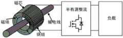
可选地,所述感应取能单元包括套设在输电线上的环形磁芯和绕制在所述环形磁芯上的感应线圈绕组。Optionally, the inductive energy harvesting unit includes an annular magnetic core sheathed on the transmission line and an induction coil winding wound on the annular magnetic core.
可选地,按照系统输出最大功率时的电磁等效关系确定取能角β,按照2α+β=π的约束关系确定最优移相角α,从而根据最优移相角α控制MOS管S1和MOS管S2的初始导通角,在最佳初始导通时间点t0opt前,控制器输出高电平驱动MOS管S1和MOS管S2,在取能角β范围内,控制器输出低电平驱动MOS管S1和MOS管S2。Optionally, the energy-taking angle β is determined according to the electromagnetic equivalent relationship when the system outputs the maximum power, and the optimal phase-shift angle α is determined according to the constraint relationship of 2α+β=π, so that the MOS transistor S is controlled according to the optimal phase-shift angle α1 and the initial conduction angle of MOS transistorS2 , before the optimal initial conduction time point t0opt , the controller outputs a high level to drive MOS transistorS1 and MOS transistorS2 , within the range of energy harvesting angle β, control The device outputs low level to drive MOS transistor S1 and MOS transistor S2 .
本发明的效果是:Effect of the present invention is:
本发明提出的一种基于阻抗匹配的感应能量收集系统最大功率追踪方法,通过半有源整流电路,分析不同应用场景下的最大功率输出条件,以系统非线性磁特性的阻抗匹配思路为基础,实现了宽负载范围、宽感应电流范围的最大功率输出,有效地提高了磁能量收集系统的输出功率密度。同时,本发明只对半有源整流器的初始导通角实行控制,实现了负载或感应电流变化条件下系统的最大功率追踪,控制系统简单,具有良好的移相控制效果。A method for tracking the maximum power of an inductive energy harvesting system based on impedance matching proposed by the present invention uses a semi-active rectifier circuit to analyze the maximum power output conditions in different application scenarios, based on the idea of impedance matching of the nonlinear magnetic characteristics of the system, The maximum power output with wide load range and wide induction current range is realized, and the output power density of the magnetic energy harvesting system is effectively improved. At the same time, the invention only controls the initial conduction angle of the semi-active rectifier, realizes the maximum power tracking of the system under the condition of load or induced current variation, has a simple control system, and has good phase-shift control effect.
附图说明Description of drawings
为了更清楚地说明本发明具体实施方式或现有技术中的技术方案,下面将对具体实施方式或现有技术描述中所需要使用的附图作简单地介绍。In order to more clearly illustrate the specific embodiments of the present invention or the technical solutions in the prior art, the following will briefly introduce the drawings that need to be used in the description of the specific embodiments or the prior art.
图1为本发明的控制流程图;Fig. 1 is a control flowchart of the present invention;
图2为本发明的系统架构图;Fig. 2 is a system architecture diagram of the present invention;
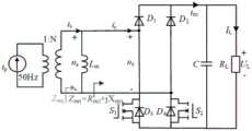
图3为图2的等效电路原理图;Fig. 3 is the equivalent circuit schematic diagram of Fig. 2;
图4为本发明具体实施例中整流器输入电压电流、输出电流及负载电流波形图。Fig. 4 is a waveform diagram of input voltage current, output current and load current of a rectifier in a specific embodiment of the present invention.
具体实施方式Detailed ways
下面将结合附图对本发明技术方案的实施例进行详细的描述。以下实施例仅用于更加清楚地说明本发明的技术方案,因此只作为示例,而不能以此来限制本发明的保护范围。Embodiments of the technical solutions of the present invention will be described in detail below in conjunction with the accompanying drawings. The following examples are only used to illustrate the technical solutions of the present invention more clearly, and therefore are only examples, rather than limiting the protection scope of the present invention.
需要注意的是,除非另有说明,本申请使用的技术术语或者科学术语应当为本发明所属领域技术人员所理解的通常意义。It should be noted that, unless otherwise specified, the technical terms or scientific terms used in this application shall have the usual meanings understood by those skilled in the art to which the present invention belongs.
如图1、图2、图3所示,本实施例提供了一种基于阻抗匹配的感应能量收集系统最大功率追踪方法,包括以下步骤:As shown in Fig. 1, Fig. 2 and Fig. 3, this embodiment provides a maximum power tracking method for an inductive energy harvesting system based on impedance matching, including the following steps:
S1:构建感应能量收集系统模型,在感应取能单元和负载之间设置半有源整流电路;S1: Construct the model of the inductive energy harvesting system, and set up a semi-active rectification circuit between the inductive energy harvesting unit and the load;
在本实施例中,感应取能单元包括套设在输电线上的环形磁芯和绕制在所述环形磁芯上的感应线圈绕组,半有源整流电路为二极管D1、二极管D2,MOS管S1和MOS管S2构成的有源可控整流电路;在半有源整流电路的输出端设置有滤波电容C,环形磁芯收集输电线周围的时变磁场,在感应线圈绕组末端感应出交流电压,经过半有源整流电路和滤波电容后为负载电阻提供稳定输出电压。In this embodiment, the inductive energy harvesting unit includes a ring-shaped magnetic core sleeved on the transmission line and an induction coil winding wound on the ring-shaped magnetic core. The semi-active rectification circuit is a diode D1 and a diode D2 . The active controllable rectification circuit composed of MOS transistor S1 and MOS transistor S2 ; a filter capacitor C is set at the output end of the semi-active rectification circuit, and the ring magnetic core collects the time-varying magnetic field around the transmission line, and at the end of the induction coil winding The AC voltage is induced, and after a semi-active rectification circuit and a filter capacitor, a stable output voltage is provided for the load resistor.
S2:确定系统固有参数,包括感应取能单元的磁芯截面积A、饱和磁感应强度Bsat、感应线圈绕组匝数N以及系统工作角频率ω;S2: Determine the inherent parameters of the system, including the core cross-sectional area A of the induction energy harvesting unit, the saturation magnetic induction Bsat , the number of turns of the induction coil winding N, and the operating angular frequency ω of the system;
S3:确定系统可变参数,包括获取负载电阻值RL和感应取能单元的感应电流,并确定感应电流有效值Is;S3: Determine the variable parameters of the system, including obtaining the load resistance valueRL and the induction current of the induction energy-taking unit, and determining the effective value Is of the induction current;
在感应能量收集系统中设置有控制器和电流传感器,控制器通过电流传感器确定感应电流有效值Is,针对负载固定的场景,负载电阻值RL可以预先设定在控制器中,针对负载可变的场景,负载可拆卸式连接在所述半有源整流电路的输出端,且负载等效电阻可变,具体实施时,在所述负载接入所述半有源整流电路中时,检测负载电阻值RL,控制器确定电阻值RL。The inductive energy harvesting system is provided with a controller and a current sensor. The controller determines the effective value of the induced current Is through the current sensor. For a scenario where the load is fixed, the load resistance value RL can be preset in the controller. For the load that can be In a changing scenario, the load is detachably connected to the output end of the semi-active rectifier circuit, and the equivalent resistance of the load is variable. During specific implementation, when the load is connected to the semi-active rectifier circuit, the detection The load resistance valueRL , the controller determines the resistance valueRL .
S4:按照
具体实施时,控制器通过发出PWM波形控制MOS管S1和MOS管S2的移相角度。此外,按照系统输出最大功率时的电磁等效关系确定取能角β,按照2α+β=π的约束关系确定最优移相角α,从而根据最优移相角α控制MOS管S1和MOS管S2的初始导通角,在最佳初始导通时间点t0opt前,控制器输出高电平驱动MOS管S1和MOS管S2,在取能角β范围内,控制器输出低电平驱动MOS管S1和MOS管S2,具体控制效果如图4所示。During specific implementation, the controller controls the phase shift angles of the MOS transistor S1 and the MOS transistor S2 by sending out a PWM waveform. In addition, the energy acquisition angle β is determined according to the electromagnetic equivalent relationship when the system outputs the maximum power, and the optimal phase shift angle α is determined according to the constraint relationship of 2α+β=π, so that the MOS transistors S1 and MOS are controlled according to the optimal phase shift angle α The initial conduction angle of the MOS transistorS2 . Before the optimal initial conduction time point t0opt , the controller outputs a high level to drive the MOS transistorS1 and the MOS transistorS2 . Within the range of the energy acquisition angle β, the controller outputs MOS transistor S1 and MOS transistor S2 are driven at a low level, and the specific control effect is shown in FIG. 4 .
结合图3可以看出,负载上电流为IL,二次侧等效阻抗和等效输出外阻抗分别为Zseq和Zout,根据上述过程可以理解,忽略磁芯励磁与涡流损耗、原副边漏磁损耗和二次侧绕组损耗,简化系统取能模型,可以进行理想化等效,具体设计思路分析如下:Combining with Figure 3, it can be seen that the current on the load is IL , and the equivalent impedance of the secondary side and the equivalent output external impedance are Zseq and Zout respectively. According to the above process, it can be understood that the core excitation and eddy current loss, primary and secondary The side leakage magnetic loss and the secondary side winding loss simplify the system energy acquisition model and can be idealized and equivalent. The specific design ideas are analyzed as follows:
根据能量守恒,整流器前端的有功功率应等于负载上消耗的有功功率:According to energy conservation, the active power at the front end of the rectifier should be equal to the active power dissipated on the load:
Pa=PL (1)Pa =PL (1)
Pa的平均值等于瞬时功率积分的平均,即:The average value of Pa is equal to the average of the instantaneous power integral, that is:

其中,ω=2π/T为系统的工作角频率,T是系统的工作周期。Among them, ω=2π/T is the working angular frequency of the system, and T is the working period of the system.
负载电流可以表示为:The load current can be expressed as:

负载功率表示为:The load power is expressed as:

因此,等效外阻抗可以表示为:Therefore, the equivalent external impedance can be expressed as:

由上式(5)可知,等效外阻抗可以通过初始导通时间t0和系统取能时间tsat的调节进行控制。It can be known from the above formula (5) that the equivalent external impedance can be controlled by adjusting the initial turn-on time t0 and the system energy acquisition time tsat .
根据法拉第电磁感应定理,磁芯累积磁通量等于感应电压与时间的积分,表示为:According to Faraday's electromagnetic induction theorem, the cumulative magnetic flux of the magnetic core is equal to the integral of the induced voltage and time, expressed as:

其中,us为副边感应电压,“2”表示为磁感应强度从-Bsat到+Bsat的过程。Among them, us is the induced voltage of the secondary side, and "2" represents the process of the magnetic induction intensity from -Bsat to +Bsat .
基于电路定理,us可以表示为:Based on the circuit theorem, us can be expressed as:
us=is|Zseq| (7)us =is |Zseq | (7)
对副边电压和电流进行傅里叶分析,得出基波分量为:Fourier analysis is carried out on the secondary side voltage and current, and the fundamental component is obtained as:

将式(3)代入式(8),∣Zseq∣可以表示为:Substituting formula (3) into formula (8), ∣Zseq ∣ can be expressed as:

将式(7)和(9)代入式(6),系统存在的磁特性关系为:Substituting equations (7) and (9) into equation (6), the magnetic characteristic relationship of the system is:

结合式(4)和式(10),系统输出功率可以通过调节初始导通时间t0和系统取能时间tsat进行控制,而初始导通时间t0和系统取能时间tsat由于磁特性的限制存在特定的耦合关系。因此通过对输出功率求极值可以在考虑非线性磁特性的情况下实现最大功率输出。Combining Equation (4) and Equation (10), the system output power can be controlled by adjusting the initial on-time t0 and the system energy acquisition time tsat , and the initial on-time t0 and the system energy acquisition time tsat are due to the magnetic characteristics There is a specific coupling relationship between the constraints. Therefore, the maximum power output can be achieved by taking the extreme value of the output power while considering the nonlinear magnetic characteristics.
在式(10)的基础上,输出功率对初始移相角进行求导,一次导公式表示为:On the basis of formula (10), the output power is derived from the initial phase shift angle, and the first derivative formula is expressed as:

其中,a、b、c表示为:Among them, a, b, c are expressed as:

d较为复杂,包含了三角及高次函数等,表示为:d is more complex, including trigonometric and higher-order functions, etc., expressed as:

在一个取能周期中,存在如下限制:In a power-taking cycle, there are the following restrictions:

因此,b不可能为零,通过绘制三维图,发现d恒大于零。根据式(10),c也不为零,即:若系统输出最大功率,式(11)为零,即a为零时,系统输出功率最大,此时系统内外阻抗实现匹配。此时恒成立的条件表示为:Therefore, b cannot be zero. By drawing a three-dimensional diagram, it is found that d is always greater than zero. According to formula (10), c is also not zero, that is, if the system outputs the maximum power, formula (11) is zero, that is, when a is zero, the system output power is maximum, and the internal and external impedance of the system is matched at this time. At this time, the condition of constant establishment is expressed as:
2α+β=π (15)2α+β=π (15)
将式(15)代入式(10),可以得出输出最大功率时的最优初始导通时间t0和系统取能时间tsat可以表示为:Substituting Equation (15) into Equation (10), it can be obtained that the optimal initial turn-on time t0 and the system energy acquisition time tsat when outputting maximum power can be expressed as:

从理论上,α必须小于π,β必须大于0,在系统磁特性限制下,α和β存在耦合关系,每一个α对应一个特定的β,通过对α的调节对等效外阻抗进行调节,最后发现当2α+β=π时,即阻抗角为0,系统输出最大功率。基于不同应用场景下的取能参数,通过PWM发波控制S1和S2的移相角,精确实现磁能量收集系统的最大功率追踪。Theoretically, α must be smaller than π, and β must be greater than 0. Under the limitation of the magnetic characteristics of the system, there is a coupling relationship between α and β, each α corresponds to a specific β, and the equivalent external impedance is adjusted by adjusting α. Finally, it is found that when 2α+β=π, that is, the impedance angle is 0, the system outputs the maximum power. Based on the energy harvesting parameters in different application scenarios, the phase shift angle of S1 and S2 is controlled by PWM wave transmission, and the maximum power tracking of the magnetic energy harvesting system is accurately realized.
最后需要说明的是,以上各实施例仅用以说明本发明的技术方案,而非对其限制;尽管参照前述各实施例对本发明进行了详细的说明,本领域的普通技术人员应当理解:其依然可以对前述各实施例所记载的技术方案进行修改,或者对其中部分或者全部技术特征进行等同替换;而这些修改或者替换,并不使相应技术方案的本质脱离本发明各实施例技术方案的范围,这样的变换均应涵盖在本发明的权利要求和说明书的范围当中。Finally, it should be noted that the above embodiments are only used to illustrate the technical solutions of the present invention, rather than limiting them; although the present invention has been described in detail with reference to the foregoing embodiments, those of ordinary skill in the art should understand that: It is still possible to modify the technical solutions described in the foregoing embodiments, or perform equivalent replacements for some or all of the technical features; and these modifications or replacements do not make the essence of the corresponding technical solutions deviate from the technical solutions of the various embodiments of the present invention. Such changes should be included within the scope of the claims and description of the present invention.
Claims (5)
Translated fromChinese
Priority Applications (1)
| Application Number | Priority Date | Filing Date | Title |
|---|---|---|---|
| CN202210501972.3ACN114785168B (en) | 2022-05-10 | 2022-05-10 | Maximum Power Tracking Method for Inductive Energy Harvesting System Based on Impedance Matching |
Applications Claiming Priority (1)
| Application Number | Priority Date | Filing Date | Title |
|---|---|---|---|
| CN202210501972.3ACN114785168B (en) | 2022-05-10 | 2022-05-10 | Maximum Power Tracking Method for Inductive Energy Harvesting System Based on Impedance Matching |
Publications (2)
| Publication Number | Publication Date |
|---|---|
| CN114785168A CN114785168A (en) | 2022-07-22 |
| CN114785168Btrue CN114785168B (en) | 2023-05-19 |
Family
ID=82436731
Family Applications (1)
| Application Number | Title | Priority Date | Filing Date |
|---|---|---|---|
| CN202210501972.3AActiveCN114785168B (en) | 2022-05-10 | 2022-05-10 | Maximum Power Tracking Method for Inductive Energy Harvesting System Based on Impedance Matching |
Country Status (1)
| Country | Link |
|---|---|
| CN (1) | CN114785168B (en) |
Citations (2)
| Publication number | Priority date | Publication date | Assignee | Title |
|---|---|---|---|---|
| CN108683229A (en)* | 2018-05-31 | 2018-10-19 | 西安理工大学 | A kind of electric vehicle wireless charging pair side output control system and its control method |
| CN113839469A (en)* | 2021-10-26 | 2021-12-24 | 澳门大学 | Wireless power transmitting terminal, wireless power receiving terminal and photovoltaic power generation system |
Family Cites Families (16)
| Publication number | Priority date | Publication date | Assignee | Title |
|---|---|---|---|---|
| US8169185B2 (en)* | 2006-01-31 | 2012-05-01 | Mojo Mobility, Inc. | System and method for inductive charging of portable devices |
| CN102307017B (en)* | 2011-09-16 | 2014-09-10 | 浙江大学 | Control method applied to active-clamp flyback miniature photovoltaic grid-connected inverter device |
| CN103208923B (en)* | 2012-04-24 | 2015-03-18 | 盐城工学院 | Control method of power converter for converting input high-frequency alternative-current square wave into output direct current |
| CN103401421B (en)* | 2013-07-30 | 2015-08-19 | 浙江大学 | A kind of control circuit of Boost converter |
| EP2928038A1 (en)* | 2014-03-31 | 2015-10-07 | ABB Technology AG | Inductive power transfer system and method for operating an inductive power transfer system |
| CN106452108A (en)* | 2016-11-04 | 2017-02-22 | 南京航空航天大学 | Ultrahigh frequency rectification conversion circuit and impedance matching method thereof based on Class E converter |
| US11139658B2 (en)* | 2017-05-11 | 2021-10-05 | Signify Holding B.V. | Power conversion system and method |
| KR102688640B1 (en)* | 2018-11-26 | 2024-07-24 | 엘지전자 주식회사 | Photovoltaic module |
| CN209962848U (en)* | 2019-02-21 | 2020-01-17 | 珠海市海威尔电器有限公司 | Magnetic ring of self-excitation push-pull type transformer and self-excitation push-pull type transformer |
| CN110048471A (en)* | 2019-05-23 | 2019-07-23 | 哈尔滨工业大学 | A kind of improved magnetic field energy collects self-optimization method and system |
| CN110979042B (en)* | 2019-12-20 | 2023-07-28 | 中兴新能源汽车有限责任公司 | Wireless charging receiving device, wireless charging control method and wireless charging system |
| CN112600287B (en)* | 2020-10-16 | 2022-12-09 | 国网湖南省电力有限公司 | Impedance matching type power transmission line energy taking device with air gap adjusting function and application method thereof |
| CN112631227B (en)* | 2020-12-28 | 2022-11-11 | 北京交通大学 | Magnetic induction energy extraction device and multi-data fusion energy Internet of things distributed information substation system based on electric energy extraction |
| CN112787516B (en)* | 2021-01-25 | 2022-04-26 | 西南交通大学 | Four-port converter based on center-tapped transformer and control method |
| CN113343616B (en)* | 2021-04-29 | 2023-05-23 | 西安交通大学 | Optimal design method and system for current transformer power supply |
| CN113410913A (en)* | 2021-06-17 | 2021-09-17 | 丰宇宸 | MC-WPT system based on Sepic circuit impedance matching and maximum efficiency tracking method thereof |
- 2022
- 2022-05-10CNCN202210501972.3Apatent/CN114785168B/enactiveActive
Patent Citations (2)
| Publication number | Priority date | Publication date | Assignee | Title |
|---|---|---|---|---|
| CN108683229A (en)* | 2018-05-31 | 2018-10-19 | 西安理工大学 | A kind of electric vehicle wireless charging pair side output control system and its control method |
| CN113839469A (en)* | 2021-10-26 | 2021-12-24 | 澳门大学 | Wireless power transmitting terminal, wireless power receiving terminal and photovoltaic power generation system |
Also Published As
| Publication number | Publication date |
|---|---|
| CN114785168A (en) | 2022-07-22 |
Similar Documents
| Publication | Publication Date | Title |
|---|---|---|
| Zhu et al. | Output power stabilization for wireless power transfer system employing primary-side-only control | |
| CN202444333U (en) | Frequency tracking control device of magnetic-coupling resonance wireless power transmission system | |
| CN109149942B (en) | Multi-frequency-band control method for high-frequency resonant DC transformer | |
| CN104779672B (en) | A kind of wireless charging system being applicable to cell performance load | |
| CN103560593A (en) | Electric field coupled power transfer system and control method based on novel topology | |
| JP6259124B2 (en) | Transmission system and method for inductive charging of electrically driven vehicle, and vehicle configuration | |
| JP2014506111A (en) | System for wireless power transmission | |
| JP2016534698A (en) | Impedance tuning | |
| CN110429718B (en) | A constant current/constant voltage control method for wireless power transfer system based on primary side parameter identification | |
| CN104753152A (en) | Constant current-constant voltage composite topological sensing type charging system | |
| Sun et al. | Self-contained wireless Hall current sensor applied for two-wire zip-cords | |
| CN102427281A (en) | Method for designing topological structure of wireless energy transmission system based on condition criterion | |
| CN103312050B (en) | Active initiatively accepts wireless energy transfer method and device | |
| CN116032027A (en) | Magnetic field energy collection system based on series capacitor and power boosting method thereof | |
| CN111404209A (en) | Novel low-frequency high-power wireless power transmission system device | |
| Huh et al. | Maximizing output power using a magnetic energy harvesting system considering the relationship between harvesting time and induced voltage due to a change of airgap | |
| CN107733093A (en) | A kind of Capacitance Coupled resonance type wireless energy transmission system and method | |
| CN114785168B (en) | Maximum Power Tracking Method for Inductive Energy Harvesting System Based on Impedance Matching | |
| CN109067005B (en) | Contactless power supply device for rotating electromechanical apparatus | |
| Li et al. | A communication-free WPT system based on transmitter-side hybrid topology switching for battery charging applications | |
| CN118801540A (en) | A multi-device constant voltage wireless charging system with adjustable output power | |
| JP7296803B2 (en) | sensor terminal | |
| CN117728594A (en) | A high-frequency switching oscillation non-contact energy collection device and method | |
| CN110890796A (en) | Wireless electric energy transmission method and system insensitive to transmission distance | |
| JP2017163647A (en) | Electromagnetic field resonance wireless power supply method and power supply system |
Legal Events
| Date | Code | Title | Description |
|---|---|---|---|
| PB01 | Publication | ||
| PB01 | Publication | ||
| SE01 | Entry into force of request for substantive examination | ||
| SE01 | Entry into force of request for substantive examination | ||
| GR01 | Patent grant | ||
| GR01 | Patent grant |