CN114782474A - Adaptive compression method, device and storage medium for locking screw - Google Patents
Adaptive compression method, device and storage medium for locking screwDownload PDFInfo
- Publication number
- CN114782474A CN114782474ACN202210529597.3ACN202210529597ACN114782474ACN 114782474 ACN114782474 ACN 114782474ACN 202210529597 ACN202210529597 ACN 202210529597ACN 114782474 ACN114782474 ACN 114782474A
- Authority
- CN
- China
- Prior art keywords
- network
- sub
- node
- screw hole
- screw holes
- Prior art date
- Legal status (The legal status is an assumption and is not a legal conclusion. Google has not performed a legal analysis and makes no representation as to the accuracy of the status listed.)
- Granted
Links
Images


Classifications
- G—PHYSICS
- G06—COMPUTING OR CALCULATING; COUNTING
- G06T—IMAGE DATA PROCESSING OR GENERATION, IN GENERAL
- G06T7/00—Image analysis
- G06T7/10—Segmentation; Edge detection
- G06T7/13—Edge detection
- G—PHYSICS
- G06—COMPUTING OR CALCULATING; COUNTING
- G06T—IMAGE DATA PROCESSING OR GENERATION, IN GENERAL
- G06T7/00—Image analysis
- G06T7/0002—Inspection of images, e.g. flaw detection
- G06T7/0004—Industrial image inspection
- G—PHYSICS
- G06—COMPUTING OR CALCULATING; COUNTING
- G06T—IMAGE DATA PROCESSING OR GENERATION, IN GENERAL
- G06T7/00—Image analysis
- G06T7/10—Segmentation; Edge detection
- G06T7/11—Region-based segmentation
- G—PHYSICS
- G06—COMPUTING OR CALCULATING; COUNTING
- G06T—IMAGE DATA PROCESSING OR GENERATION, IN GENERAL
- G06T7/00—Image analysis
- G06T7/70—Determining position or orientation of objects or cameras
- G06T7/73—Determining position or orientation of objects or cameras using feature-based methods
Landscapes
- Engineering & Computer Science (AREA)
- Computer Vision & Pattern Recognition (AREA)
- Physics & Mathematics (AREA)
- General Physics & Mathematics (AREA)
- Theoretical Computer Science (AREA)
- Quality & Reliability (AREA)
- Image Analysis (AREA)
Abstract
Translated fromChinese
Description
Translated fromChinese技术领域technical field
本发明涉及螺钉锁附技术领域,特别涉及一种锁螺钉自适应压紧方法、装置及存储介质。The present invention relates to the technical field of screw locking, and in particular, to a self-adaptive compression method, device and storage medium for locking screws.
背景技术Background technique
螺钉锁付是家具制造业装配过程中的关键环节,随着近年来中国城市化进程的加快发展,商品房成交量的不断扩大,及居民消费结构升级与消费观念向时尚,环保和多功能方向的转变,定制家具行业的份额和规模越来越大。Screw lock payment is a key link in the assembly process of furniture manufacturing industry. With the accelerated development of China's urbanization process in recent years, the continuous expansion of commercial housing transactions, and the upgrading of residents' consumption structure and consumption concepts are trending towards fashion, environmental protection and multi-functionality. With the transformation, the share and scale of the custom furniture industry is increasing.
在对家居板材进行螺钉锁附时,工件的装夹和固定也是锁附操作的一个重要前提。传统装夹方式需要根据工件形状制作专用夹具,或调整夹具结构,完成固定操作,此方法适合标准件,在处理定制家具柜体板材这种形状多变的工件时,效率较低,人工成本高。When screw-locking the home panel, the clamping and fixing of the workpiece is also an important prerequisite for the locking operation. The traditional clamping method needs to make a special fixture according to the shape of the workpiece, or adjust the fixture structure to complete the fixing operation. This method is suitable for standard parts. When dealing with workpieces with variable shapes such as customized furniture cabinets, the efficiency is low and labor costs are high. .
发明内容SUMMARY OF THE INVENTION
本申请实施例提供了一种锁螺钉自适应压紧方法、装置及存储介质。为了对披露的实施例的一些方面有一个基本的理解,下面给出了简单的概括。该概括部分不是泛泛评述,也不是要确定关键/重要组成元素或描绘这些实施例的保护范围。其唯一目的是用简单的形式呈现一些概念,以此作为后面的详细说明的序言。Embodiments of the present application provide an adaptive compression method, device and storage medium for a locking screw. In order to provide a basic understanding of some aspects of the disclosed embodiments, a brief summary is given below. This summary is not intended to be an extensive review, nor is it intended to identify key/critical elements or delineate the scope of protection of these embodiments. Its sole purpose is to present some concepts in a simplified form as a prelude to the detailed description that follows.
第一方面,本申请实施例提供了一种锁螺钉自适应压紧方法,包括:In a first aspect, an embodiment of the present application provides an adaptive compression method for a locking screw, including:
根据全局相机和局部双目立体相机对板材上的螺孔进行定位;Position the screw holes on the plate according to the global camera and the local binocular stereo camera;
根据定位后的螺孔形成网络图,并根据网络图以及预设的网络分割算法确定最优压紧位置;A network diagram is formed according to the positioned screw holes, and the optimal compression position is determined according to the network diagram and the preset network segmentation algorithm;
控制压紧机构在最优压紧位置压紧固定板材。Control the pressing mechanism to press and fix the plate at the optimal pressing position.
在一些可选地实施例中,根据定位后的螺孔形成网络图,包括:In some optional embodiments, a network diagram is formed according to the positioned screw holes, including:
将螺孔作为网络图中的节点;Use screw holes as nodes in the network diagram;
将螺孔之间的连线作为网络图中的边;Use the connection between the screw holes as an edge in the network diagram;
将螺孔之间的距离作为网络图中边的权重。Take the distance between screw holes as the weight of the edges in the network graph.
在一些可选地实施例中,根据网络图以及预设的网络分割算法确定最优压紧位置,包括:In some optional embodiments, the optimal compression position is determined according to the network diagram and a preset network segmentation algorithm, including:
将网络图划分为多个子网络;Divide the network graph into multiple sub-networks;
根据相邻子网络间边界点的中位线确定最优压紧位置。The optimal compaction position is determined according to the median line of boundary points between adjacent sub-networks.
在一些可选地实施例中,将网络图划分为多个子网络,包括:In some optional embodiments, the network graph is divided into multiple sub-networks, including:
确定待划分的子网络的数量;Determine the number of sub-networks to be divided;
将网络图中的边按照权重从大到小排序;将排在前面的相应数量条权重较大的边对应的两个节点作为种子节点,种子节点的数量与子网络的数量相等;Sort the edges in the network graph according to the weight from large to small; take the two nodes corresponding to the front corresponding number of edges with larger weights as seed nodes, and the number of seed nodes is equal to the number of sub-networks;
在剩余未归属节点中找到与种子节点相连时权重最小的节点,且种子节点对应的子网络内节点的数量小于预设阈值,则将该节点归属于种子节点对应的子网络,并标记该节点为已归属节点;Find the node with the smallest weight when connected to the seed node among the remaining unattributed nodes, and the number of nodes in the sub-network corresponding to the seed node is less than the preset threshold, then the node belongs to the sub-network corresponding to the seed node, and the node is marked is a home node;
重复执行节点归属的步骤,直到剩余节点都标记为已归属节点,得到划分的多个子网络。The steps of node belonging are repeated until the remaining nodes are marked as belonging nodes, and a plurality of divided sub-networks are obtained.
在一些可选地实施例中,根据相邻子网络间边界点的中位线确定最优压紧位置,包括:In some optional embodiments, the optimal compression position is determined according to the median line of boundary points between adjacent sub-networks, including:
对每个子网络内的节点根据X轴坐标升序排序,将排序后的第一个节点作为该子网络的左临界节点,将排序后的最后一个节点作为该子网络的右临界节点;Sort the nodes in each sub-network in ascending order according to the X-axis coordinates, take the first node after sorting as the left critical node of the sub-network, and take the last node after sorting as the right critical node of the sub-network;
根据相邻子网络中x轴坐标较小的一个子网络的右临界节点和另一个子网络的左临界节点间的中位线,得到每个压紧条的最优压紧位置。According to the median line between the right critical node of one sub-network with the smaller x-axis coordinate in adjacent sub-networks and the left critical node of the other sub-network, the optimal compression position of each compression bar is obtained.
在一些可选地实施例中,根据全局相机和局部双目立体相机对板材上的螺孔进行定位,包括:In some optional embodiments, the screw holes on the plate are positioned according to the global camera and the local binocular stereo camera, including:
根据全局相机获取的全局图像进行板材边缘检测,得到板材边缘区域坐标范围;According to the global image obtained by the global camera, the edge of the plate is detected, and the coordinate range of the edge area of the plate is obtained;
在板材边缘区域坐标范围内进行螺孔区域定位,得到在板材边缘区域坐标范围内的螺孔区域位置特征;Position the screw hole area within the coordinate range of the plate edge area, and obtain the position feature of the screw hole area within the coordinate range of the plate edge area;
基于螺孔区域位置特征划分多工位各自的工作区域;Divide the respective working areas of the multi-station based on the position characteristics of the screw hole area;
分别对每个工位的工作区域内的所有螺孔规划锁付路径;Plan the locking path for all screw holes in the working area of each station respectively;
分别基于规划的螺孔锁付路径引导载有双目立体相机的电批头移动,并采集各自移动区域内每个螺孔的局部图像;Based on the planned screw hole locking and paying paths, guide the electric screwdriver head carrying the binocular stereo camera to move, and collect local images of each screw hole in the respective moving areas;
对每个螺孔的局部图像进行轮廓提取,得到每个螺孔的深度图像轮廓图;Perform contour extraction on the local image of each screw hole to obtain the depth image contour map of each screw hole;
根据每个螺孔的深度图像轮廓图定位螺孔圆心,得到每个螺孔的图像圆心坐标。According to the depth image contour map of each screw hole, locate the center of the screw hole, and obtain the coordinates of the image center of each screw hole.
在一些可选地实施例中,方法还包括:根据每个螺孔的图像圆心坐标进行空间坐标的转换,以使得电批头根据螺孔空间圆心坐标进行锁付。In some optional embodiments, the method further includes: converting the spatial coordinates according to the coordinates of the image circle center of each screw hole, so that the electric bit is locked according to the coordinates of the spatial circle center of the screw holes.
在一些可选地实施例中,在板材边缘区域坐标范围内进行螺孔区域定位,得到在板材边缘区域坐标范围内的螺孔区域位置特征,包括:In some optional embodiments, the positioning of the screw hole area is performed within the coordinate range of the plate edge area to obtain the location features of the screw hole area within the coordinate range of the plate edge area, including:
在板材边缘区域坐标范围通过连通域分析,提取各个区域的链码表和线性表;In the coordinate range of the edge area of the plate, the chain code table and linear table of each area are extracted through connected domain analysis;
根据链码表和线性表分别计算出区域边界轮廓的长度、周长、面积及中心;Calculate the length, perimeter, area and center of the boundary contour of the region according to the chain code table and the linear table respectively;
根据区域边界轮廓的长度、周长、面积及中心,进行螺孔区域定位,得到螺孔区域位置特征。According to the length, perimeter, area and center of the regional boundary contour, the screw hole region is positioned to obtain the position feature of the screw hole region.
第二方面,本申请实施例提供了一种锁螺钉自适应压紧装置,包括:In a second aspect, an embodiment of the present application provides an adaptive compression device for locking screws, including:
螺孔定位模块,用于根据全局相机和局部双目立体相机对板材上的螺孔进行定位;The screw hole positioning module is used to position the screw holes on the plate according to the global camera and the local binocular stereo camera;
压紧位置确定模块,用于根据定位后的螺孔形成网络图,并根据网络图以及预设的网络分割算法确定最优压紧位置;The pressing position determination module is used to form a network diagram according to the positioned screw holes, and determine the optimal pressing position according to the network diagram and the preset network segmentation algorithm;
控制模块,用于控制压紧机构在最优压紧位置压紧固定板材。The control module is used to control the pressing mechanism to press and fix the plate at the optimal pressing position.
第三方面,本申请实施例提供了一种计算机可读介质,其上存储有计算机可读指令,计算机可读指令被处理器执行以实现上述实施例提供的一种锁螺钉自适应压紧方法。In a third aspect, the embodiments of the present application provide a computer-readable medium on which computer-readable instructions are stored, and the computer-readable instructions are executed by a processor to implement the method for adaptively pressing a locking screw provided by the foregoing embodiments .
本申请实施例提供的技术方案可以包括以下有益效果:The technical solutions provided by the embodiments of the present application may include the following beneficial effects:
本申请实施例提供的锁螺钉自适应压紧方法,基于视觉技术和网络分割算法,面向多变的定制化板材可以计算最优压紧位置,通过传动机构和压辊运动配合形成自适应压紧机构,根据算法计算结果,在最优压紧位置“压紧固定”板材。该方法无需制作专业夹具,加工成本明显降低,效率提升。无需在加工前人工调整夹具,效率提升,设备易用性提升。且结合视觉感知算法,可实现不同尺寸、形状板材的压紧固定。The locking screw self-adaptive pressing method provided by the embodiment of the present application, based on vision technology and network segmentation algorithm, can calculate the optimal pressing position for the changeable customized plate, and form an adaptive pressing through the movement of the transmission mechanism and the pressing roller. The mechanism, according to the calculation result of the algorithm, "compresses and fixes" the plate at the optimal compression position. The method does not require the production of professional fixtures, the processing cost is significantly reduced, and the efficiency is improved. There is no need to manually adjust the fixture before processing, the efficiency is improved, and the ease of use of the equipment is improved. And combined with the visual perception algorithm, the pressing and fixing of plates of different sizes and shapes can be realized.
应当理解的是,以上的一般描述和后文的细节描述仅是示例性和解释性的,并不能限制本发明。It is to be understood that both the foregoing general description and the following detailed description are exemplary and explanatory only and are not restrictive of the invention.
附图说明Description of drawings
此处的附图被并入说明书中并构成本说明书的一部分,示出了符合本发明的实施例,并与说明书一起用于解释本发明的原理。The accompanying drawings, which are incorporated in and constitute a part of this specification, illustrate embodiments consistent with the invention and together with the description serve to explain the principles of the invention.
图1是根据一示例性实施例示出的一种锁螺钉自适应压紧方法的流程示意图;FIG. 1 is a schematic flowchart of a method for self-adaptive compression of locking screws according to an exemplary embodiment;
图2是根据一示例性实施例示出的一种最优压紧位置的示意图;Fig. 2 is a schematic diagram showing an optimal compression position according to an exemplary embodiment;
图3是根据一示例性实施例示出的一种锁螺钉自适应压紧装置的示意图;3 is a schematic diagram of a locking screw adaptive compression device according to an exemplary embodiment;
图4是根据一示例性实施例示出的一种计算机存储介质的示意图。FIG. 4 is a schematic diagram of a computer storage medium according to an exemplary embodiment.
具体实施方式Detailed ways
以下描述和附图充分地示出本发明的具体实施方案,以使本领域的技术人员能够实践它们。The following description and drawings sufficiently illustrate specific embodiments of the invention to enable those skilled in the art to practice them.
应当明确,所描述的实施例仅仅是本发明一部分实施例,而不是全部的实施例。基于本发明中的实施例,本领域普通技术人员在没有作出创造性劳动前提下所获得的所有其它实施例,都属于本发明保护的范围。It should be understood that the described embodiments are only some, but not all, embodiments of the present invention. Based on the embodiments of the present invention, all other embodiments obtained by those of ordinary skill in the art without creative efforts shall fall within the protection scope of the present invention.
下面的描述涉及附图时,除非另有表示,不同附图中的相同数字表示相同或相似的要素。以下示例性实施例中所描述的实施方式并不代表与本发明相一致的所有实施方式。相反,它们仅是如所附权利要求书中所详述的、本发明的一些方面相一致的系统和方法的例子。Where the following description refers to the drawings, the same numerals in different drawings refer to the same or similar elements unless otherwise indicated. The implementations described in the illustrative examples below are not intended to represent all implementations consistent with the present invention. Rather, they are merely examples of systems and methods consistent with some aspects of the invention, as recited in the appended claims.
下面将结合附图对本申请实施例提供的锁螺钉自适应压紧方法进行详细介绍。参见图1,该方法具体包括以下步骤。The self-adaptive compression method for locking screws provided by the embodiments of the present application will be described in detail below with reference to the accompanying drawings. Referring to Figure 1, the method specifically includes the following steps.
S101、根据全局相机和局部双目立体相机对板材上的螺孔进行定位。S101. Position the screw holes on the plate according to the global camera and the local binocular stereo camera.
面向定制化柜体板自动锁螺丝需求,提出基于多视觉传感及双目视觉技术的螺孔精准定位方法。通过多视觉传感技术高效实现工件孔位分布识别,局部相机运动路径规划和精准孔位识别。通过双目视觉技术,排除其中已经锁付的圆形工件,准确定位需要锁付的螺孔位。Facing the demand for automatic locking screws of customized cabinet panels, a precise positioning method of screw holes based on multi-vision sensing and binocular vision technology is proposed. Through the multi-vision sensing technology, the workpiece hole position distribution identification, local camera motion path planning and accurate hole position identification are efficiently realized. Through binocular vision technology, the round workpieces that have been locked are excluded, and the screw holes that need to be locked are accurately located.
在一种可能的实现方式中,首先,根据全局相机获取的全局图像进行板材边缘检测,得到板材边缘区域坐标范围;在板材边缘区域坐标范围内进行螺孔区域定位,得到在板材边缘区域坐标范围内的螺孔区域位置特征; 基于螺孔区域位置特征划分多工位各自的工作区域;分别对每个工位的工作区域内的所有螺孔规划锁付路径;分别基于规划的螺孔锁付路径引导载有双目立体相机的电批头移动,并采集各自移动区域内每个螺孔的局部图像;对每个螺孔的局部图像进行轮廓提取,得到每个螺孔的深度图像轮廓图;根据每个螺孔的深度图像轮廓图定位螺孔圆心,得到每个螺孔的图像圆心坐标。根据每个螺孔的图像圆心坐标进行空间坐标的转换,以使得电批头根据螺孔空间圆心坐标进行锁付。In a possible implementation manner, firstly, the plate edge is detected according to the global image obtained by the global camera to obtain the coordinate range of the plate edge area; the screw hole area positioning is performed within the coordinate range of the plate edge area to obtain the coordinate range of the plate edge area The position characteristics of the screw hole area in the interior; divide the respective working areas of the multi-station based on the position characteristics of the screw hole area; plan the locking path for all the screw holes in the working area of each station respectively; The path guides the electric bit head carrying the binocular stereo camera to move, and collects the local image of each screw hole in the respective moving area; extracts the contour of the local image of each screw hole to obtain the depth image contour map of each screw hole ;Locate the center of the screw hole according to the depth image contour map of each screw hole, and obtain the coordinates of the image center of each screw hole. The spatial coordinates are converted according to the coordinates of the image center of each screw hole, so that the electric screwdriver can be locked according to the coordinates of the spatial center of the screw hole.
其中,根据全局相机获取的全局图像进行板材边缘检测,得到板材边缘区域坐标,包括:对全局相机获取的全局图像进行灰度处理;对灰度处理后的全局图像使用X轴、Y轴方向模板分别沿着X轴、Y轴做卷积,将方向模板的中心和图像上的某个像素重合,并将该像素周围的点与模板上的系数相乘,再进行梯度运算,以得到板材边缘区域坐标。The plate edge detection is performed according to the global image obtained by the global camera, and the coordinates of the plate edge area are obtained, including: performing grayscale processing on the global image obtained by the global camera; using the X-axis and Y-axis direction templates for the grayscale-processed global image Do convolution along the X-axis and Y-axis respectively, coincide the center of the direction template with a certain pixel on the image, multiply the points around the pixel with the coefficient on the template, and then perform the gradient operation to get the edge of the plate Area coordinates.
其中,所述在所述板材边缘区域坐标范围内进行螺孔区域定位,得到在板材边缘区域坐标范围内的螺孔区域位置特征,包括:在所述板材边缘区域坐标范围通过连通域分析,提取各个区域的链码表和线性表;根据链码表和线性表分别计算出区域边界轮廓的长度、周长、面积及中心;根据所述区域边界轮廓的长度、周长、面积及中心,进行螺孔区域定位,得到螺孔区域位置特征。Wherein, the positioning of the screw hole area within the coordinate range of the plate edge area to obtain the location feature of the screw hole area within the coordinate range of the plate edge area includes: extracting, through connected domain analysis, in the coordinate range of the plate edge area. The chain code table and linear table of each area; according to the chain code table and the linear table, the length, perimeter, area and center of the boundary contour of the area are respectively calculated; Position the screw hole area to obtain the position feature of the screw hole area.
其中,所述基于所述螺孔区域位置特征划分多工位各自的工作区域,包括:将螺孔转化为网络中的节点,螺孔圆心之间的路径为网络中的边,螺孔圆心间距离为边的权值,得到节点集;根据权值矩阵,将节点中的边按权值从大到小排序;选择权值最大的节点作为各工位工作范围的种子节点;在未归属节点中寻找与种子节点产生最小权值的节点,将所述最小权值的节点归属于该种子节点所在工作区域,并标记为已归属节点,直至所有节点都已标记为已归属节点,得到划分后多工位各自的工作区域。Wherein, dividing the respective working areas of the multi-station based on the location characteristics of the screw holes includes: converting the screw holes into nodes in the network, the paths between the centers of the screw holes are edges in the network, and the paths between the centers of the screw holes are the edges in the network. The distance is the weight of the edge, and the node set is obtained; according to the weight matrix, the edges in the nodes are sorted in descending order of weight; the node with the largest weight is selected as the seed node of the working range of each station; Find the node that generates the minimum weight with the seed node, attribute the node with the minimum weight to the work area where the seed node is located, and mark it as an attributable node, until all nodes have been marked as attributable nodes, and after the division is obtained Multiple workstations with their own work areas.
其中,述分别对每个工位的工作区域内的所有螺孔规划锁付路径,包括:利用蚁群算法计算电批头遍历工作区域内的每个螺孔圆心坐标并返回原处的最短距离,作为每个螺孔的螺孔锁付路径。Wherein, the above describes the planning of locking paths for all screw holes in the working area of each station, including: using the ant colony algorithm to calculate the coordinates of the center of each screw hole in the working area and returning to the original position by using the ant colony algorithm to calculate the shortest distance. , as the screw hole locking path for each screw hole.
其中,所述根据每个螺孔的深度图像轮廓图定位螺孔圆心,得到每个螺孔的图像圆心坐标,包括:在每个螺孔的深度图像轮廓图的圆心坐标和半径的最大值和最小值之间建立离散的参数空间,在参数空间对目标检测的候选区域内的每一点做变换,分别计算所有的点的圆心坐标和半径的值,得到螺孔的个数和每个螺孔的图像圆心坐标。Wherein, according to the depth image contour map of each screw hole, the center of the screw hole is located, and the image center coordinates of each screw hole are obtained, including: the center coordinates of the depth image contour map of each screw hole and the maximum value of the radius and the radius A discrete parameter space is established between the minimum values, and each point in the candidate area for target detection is transformed in the parameter space, and the center coordinates and radius values of all points are calculated separately to obtain the number of screw holes and each screw hole. The coordinates of the center of the image.
通过该步骤,可以对不同形状的板材上的螺孔进行自动定位。Through this step, the screw holes on plates with different shapes can be automatically positioned.
S102、根据定位后的螺孔形成网络图,并根据网络图以及预设的网络分割算法确定最优压紧位置。S102 , forming a network diagram according to the positioned screw holes, and determining an optimal pressing position according to the network diagram and a preset network segmentation algorithm.
基于多视觉传感及双目视觉技术进行螺孔精准定位之后,仅定位是无法完成螺钉锁附操作的,工件的装夹和固定也是锁附操作的一个重要前提。因此,根据定位后的螺孔形成网络图,并根据网络图以及预设的网络分割算法确定最优压紧位置。After accurate positioning of screw holes based on multi-vision sensing and binocular vision technology, the screw locking operation cannot be completed only by positioning. The clamping and fixing of the workpiece is also an important prerequisite for the locking operation. Therefore, a network diagram is formed according to the positioned screw holes, and the optimal pressing position is determined according to the network diagram and a preset network segmentation algorithm.
首先,根据定位后的螺孔构造网络图G,将螺孔作为网络图中的节点,节点位置即螺孔圆心坐标,将螺孔圆心之间的连线作为网络图中的边,将螺孔圆心之间的距离作为网络图中边的权重。图中节点集为C(G)。First, construct the network graph G according to the positioned screw holes, take the screw holes as the nodes in the network diagram, the node position is the coordinates of the center of the screw holes, take the connection between the centers of the screw holes as the edges in the network diagram, and use the screw holes as the nodes in the network diagram. The distance between the centers of the circles is used as the weight of the edges in the network graph. The node set in the graph is C(G).
进一步地,将构造的网络图划分为多个子网络。Further, the constructed network graph is divided into multiple sub-networks.
具体地,确定待划分的子网络的数量,可根据采用的机械臂的数量确定待划分的子网络的数量,例如,采用两个机械臂时划分两个子网络,采用四个机械臂时,划分4个子网络,可根据实际情况设定,本申请实施例不做具体限定。Specifically, to determine the number of sub-networks to be divided, the number of sub-networks to be divided can be determined according to the number of robotic arms used. For example, when two robotic arms are used, two subnets are divided; when four robotic arms are used, the number of The four sub-networks may be set according to actual conditions, and are not specifically limited in this embodiment of the present application.
将网络图中的边按照权重从大到小排序,得到排序后的数组EdgeList, 将排在前面的相应数量条权重较大的边对应的两个节点作为种子节点,种子节点的数量与子网络的数量相等,因此,可根据种子节点与子网络的数量相等,确定选取权重较大的边的数量。以设定两个子网络为例,需要两个种子节点,只选取权重最大的一条边即可,选取权值最大的边EdgeList[0],表示为


在剩余未归属节点中找到与种子节点相连时权重最小的节点,且种子节点对应的子网络内节点的数量小于预设阈值,则将该节点归属于种子节点对应的子网络,并标记该节点为已归属节点。若归属后,该子网络内节点的数量达到阈值,则将剩余未归属节点归属到其他种子节点所属的子网络。Find the node with the smallest weight when connected to the seed node among the remaining unattributed nodes, and the number of nodes in the sub-network corresponding to the seed node is less than the preset threshold, then the node belongs to the sub-network corresponding to the seed node, and the node is marked is the home node. If the number of nodes in the sub-network reaches the threshold after attribution, the remaining unattributed nodes are attributable to the sub-networks to which other seed nodes belong.
例如,在剩余未归属节点中找到与种子节点


重复执行节点归属的步骤,直到剩余节点都标记为已归属节点,得到划分的多个子网络Region_List。Repeat the steps of node attribution until the remaining nodes are marked as attribution nodes, and obtain the divided multiple sub-networkRegion_List .
其中,


进一步地,根据相邻子网络间边界点的中位线确定最优压紧位置。选择中位线的原因是为了尽量保证押紧位置两侧压力均衡,并且确保押紧位置距离边界节点的距离足够大。Further, the optimal compression position is determined according to the median line of boundary points between adjacent sub-networks. The reason for choosing the median line is to ensure that the pressure on both sides of the pressing position is balanced as much as possible, and that the distance between the pressing position and the boundary node is large enough.
首先,对每个子网络内的节点根据X轴坐标升序排序,将排序后的第一个节点作为该子网络的左临界节点,将排序后的最后一个节点作为该子网络的右临界节点。根据相邻子网络中x轴坐标较小的一个子网络的右临界节点和另一个子网络的左临界节点间的中位线,得到每个压紧条的最优压紧位置。First, the nodes in each sub-network are sorted in ascending order according to the X-axis coordinates, the first node after sorting is taken as the left critical node of the sub-network, and the last node after sorting is taken as the right critical node of the sub-network. According to the median line between the right critical node of one sub-network with the smaller x-axis coordinate in adjacent sub-networks and the left critical node of the other sub-network, the optimal compression position of each compression bar is obtained.
例如,第i个子网络的右临界节点的x轴坐标表示为


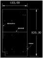
图2是根据一示例性实施例示出的一种最优压紧位置的示意图,如图2所示,找到不规则板材需锁附的子网络的边界孔位,根据两个边界孔位的连线的中位线得到最优压紧位置。Fig. 2 is a schematic diagram showing an optimal pressing position according to an exemplary embodiment. As shown in Fig. 2, the boundary hole positions of the sub-network to be locked on the irregular sheet are found. According to the connection between the two boundary hole positions The median line of the wire gets the optimal compression position.
S103、控制压紧机构在最优压紧位置压紧固定板材。S103, controlling the pressing mechanism to press and fix the plate at the optimal pressing position.
得到算法计算出来的最优压紧位置之后,控制自适应压紧机构在预定位置压紧固定板材,实现对板材的压紧固定。After the optimal pressing position calculated by the algorithm is obtained, the adaptive pressing mechanism is controlled to press and fix the plate at the predetermined position to realize the pressing and fixing of the plate.
本申请实施例提供的锁螺钉自适应压紧方法,对板材的全局图像完成螺孔的定位后,将螺孔看作网络中的节点,螺孔圆心之间的路径看作网络中的边,路径长度代表边的权值,以此形成螺孔的网络图。将寻找最优压紧位置的问题抽象为基于网络分割的结果计算最优位置的问题。具体为首先将网络划分为指定数量的子网络,然后在相邻子网络的边界点间寻找中位线作为最优压紧位置。然后控制压紧机构在最优压紧位置压紧固定板材。In the self-adaptive compression method for locking screws provided by the embodiments of the present application, after positioning the screw holes on the global image of the plate, the screw holes are regarded as nodes in the network, and the paths between the centers of the screw holes are regarded as edges in the network. The length of the path represents the weight of the edge to form a network graph of screw holes. The problem of finding the optimal compaction position is abstracted into the problem of calculating the optimal position based on the results of network segmentation. Specifically, the network is first divided into a specified number of sub-networks, and then the median line is found between the boundary points of adjacent sub-networks as the optimal compression position. Then control the pressing mechanism to press and fix the plate at the optimal pressing position.
该方法无需制作专业夹具,加工成本明显降低,效率提升。无需在加工前人工调整夹具,效率提升,设备易用性提升。且结合视觉感知算法,可实现不同尺寸、形状板材的压紧固定。The method does not require the production of professional fixtures, the processing cost is significantly reduced, and the efficiency is improved. There is no need to manually adjust the fixture before processing, the efficiency is improved, and the ease of use of the equipment is improved. And combined with the visual perception algorithm, the pressing and fixing of plates of different sizes and shapes can be realized.
本申请实施例还提供一种锁螺钉自适应压紧装置,该装置用于执行上述实施例的锁螺钉自适应压紧方法,如图3所示,该装置包括:The embodiment of the present application further provides a locking screw self-adaptive pressing device, and the device is used to perform the locking screw self-adaptive pressing method of the above-mentioned embodiment. As shown in FIG. 3 , the device includes:
螺孔定位模块301,用于根据全局相机和局部双目立体相机对板材上的螺孔进行定位;The screw
压紧位置确定模块302,用于根据定位后的螺孔形成网络图,并根据网络图以及预设的网络分割算法确定最优压紧位置;The pressing
控制模块303,用于控制压紧机构在最优压紧位置压紧固定板材。The
该装置无需制作专业夹具,加工成本明显降低,效率提升。无需在加工前人工调整夹具,效率提升,设备易用性提升。且结合视觉感知算法,可实现不同尺寸、形状板材的压紧固定。The device does not require the production of professional fixtures, the processing cost is significantly reduced, and the efficiency is improved. There is no need to manually adjust the fixture before processing, the efficiency is improved, and the ease of use of the equipment is improved. And combined with the visual perception algorithm, the pressing and fixing of plates of different sizes and shapes can be realized.
需要说明的是,上述实施例提供的锁螺钉自适应压紧装置在执行锁螺钉自适应压紧方法时,仅以上述各功能模块的划分进行举例说明,实际应用中,可以根据需要而将上述功能分配由不同的功能模块完成,即将设备的内部结构划分成不同的功能模块,以完成以上描述的全部或者部分功能。另外,上述实施例提供的锁螺钉自适应压紧装置与锁螺钉自适应压紧方法实施例属于同一构思,其体现实现过程详见方法实施例,这里不再赘述。It should be noted that, when the locking screw self-adaptive pressing device provided by the above embodiment performs the locking screw self-adaptive pressing method, only the division of the above-mentioned functional modules is used as an example for illustration. The function distribution is completed by different function modules, that is, the internal structure of the device is divided into different function modules to complete all or part of the functions described above. In addition, the locking screw self-adaptive pressing device and the locking screw self-adaptive pressing method provided in the above embodiments belong to the same concept, and the embodiment and implementation process thereof are detailed in the method embodiment, which will not be repeated here.
本申请实施例还提供一种与前述实施例所提供的锁螺钉自适应压紧方法对应的计算机可读存储介质,请参考图4,其示出的计算机可读存储介质为光盘400,其上存储有计算机程序(即程序产品),计算机程序在被处理器运行时,会执行前述任意实施例所提供的锁螺钉自适应压紧方法。Embodiments of the present application further provide a computer-readable storage medium corresponding to the locking screw adaptive compression method provided by the foregoing embodiments, please refer to FIG. 4 , the computer-readable storage medium shown is an
需要说明的是,计算机可读存储介质的例子还可以包括,但不限于相变内存(PRAM)、静态随机存取存储器 (SRAM)、动态随机存取存储器 (DRAM)、其他类型的随机存取存储器 (RAM)、只读存储器 (ROM)、电可擦除可编程只读存储器 (EEPROM)、快闪记忆体或其他光学、磁性存储介质,在此不再一一赘述。It should be noted that examples of computer-readable storage media may also include, but are not limited to, phase-change memory (PRAM), static random access memory (SRAM), dynamic random access memory (DRAM), other types of random access memory Memory (RAM), Read-Only Memory (ROM), Electrically Erasable Programmable Read-Only Memory (EEPROM), Flash Memory or other optical and magnetic storage media will not be repeated here.
本申请的上述实施例提供的计算机可读存储介质与本申请实施例提供的锁螺钉自适应压紧方法出于相同的发明构思,具有与其存储的应用程序所采用、运行或实现的方法相同的有益效果。The computer-readable storage medium provided by the above-mentioned embodiments of the present application and the method for self-adaptive tightening of locking screws provided by the embodiments of the present application are based on the same inventive concept, and have the same methods adopted, run or implemented by the stored application programs. beneficial effect.
以上实施例的各技术特征可以进行任意的组合,为使描述简洁,未对上述实施例中的各个技术特征所有可能的组合都进行描述,然而,只要这些技术特征的组合不存在矛盾,都应当认为是本说明书记载的范围。The technical features of the above embodiments can be combined arbitrarily. In order to make the description simple, all possible combinations of the technical features in the above embodiments are not described. However, as long as there is no contradiction in the combination of these technical features It is considered to be the range described in this specification.
以上实施例仅表达了本发明的几种实施方式,其描述较为具体和详细,但并不能因此而理解为对本发明专利范围的限制。应当指出的是,对于本领域的普通技术人员来说,在不脱离本发明构思的前提下,还可以做出若干变形和改进,这些都属于本发明的保护范围。因此,本发明专利的保护范围应以所附权利要求为准。The above embodiments only represent several embodiments of the present invention, and the descriptions thereof are specific and detailed, but should not be construed as a limitation on the scope of the patent of the present invention. It should be pointed out that for those of ordinary skill in the art, without departing from the concept of the present invention, several modifications and improvements can also be made, which all belong to the protection scope of the present invention. Therefore, the protection scope of the patent of the present invention should be subject to the appended claims.
Claims (10)
Priority Applications (1)
| Application Number | Priority Date | Filing Date | Title |
|---|---|---|---|
| CN202210529597.3ACN114782474B (en) | 2022-05-16 | 2022-05-16 | Locking screw self-adaptive compression method, device and storage medium |
Applications Claiming Priority (1)
| Application Number | Priority Date | Filing Date | Title |
|---|---|---|---|
| CN202210529597.3ACN114782474B (en) | 2022-05-16 | 2022-05-16 | Locking screw self-adaptive compression method, device and storage medium |
Publications (2)
| Publication Number | Publication Date |
|---|---|
| CN114782474Atrue CN114782474A (en) | 2022-07-22 |
| CN114782474B CN114782474B (en) | 2022-12-20 |
Family
ID=82436573
Family Applications (1)
| Application Number | Title | Priority Date | Filing Date |
|---|---|---|---|
| CN202210529597.3AActiveCN114782474B (en) | 2022-05-16 | 2022-05-16 | Locking screw self-adaptive compression method, device and storage medium |
Country Status (1)
| Country | Link |
|---|---|
| CN (1) | CN114782474B (en) |
Citations (10)
| Publication number | Priority date | Publication date | Assignee | Title |
|---|---|---|---|---|
| US20090136103A1 (en)* | 2005-06-24 | 2009-05-28 | Milan Sonka | System and methods for image segmentation in N-dimensional space |
| CN108228972A (en)* | 2016-12-12 | 2018-06-29 | 德国弗劳恩霍夫应用研究促进协会 | Determine the method and computer program of the arrangement of at least one circuit for Reconfigurable logic device |
| CN109509197A (en)* | 2018-09-26 | 2019-03-22 | 沈阳东软医疗系统有限公司 | A kind of method, apparatus, equipment and storage medium for dividing area-of-interest |
| CN110298842A (en)* | 2019-06-10 | 2019-10-01 | 上海工程技术大学 | A kind of rail clip image position method based on super-pixel node sequencing |
| CN110546958A (en)* | 2017-05-18 | 2019-12-06 | 利弗有限公司 | Apparatus, system and method for wireless multi-link vehicle communication |
| CN110841220A (en)* | 2019-12-09 | 2020-02-28 | 国网智能科技股份有限公司 | A substation intelligent fire protection system and method |
| CN111932517A (en)* | 2020-08-11 | 2020-11-13 | 上海柏楚电子科技股份有限公司 | Contour mapping method and device for excess material plate, electronic equipment and storage medium |
| CN112288693A (en)* | 2020-10-19 | 2021-01-29 | 佛山(华南)新材料研究院 | Round hole detection method and device, electronic equipment and storage medium |
| CN114013060A (en)* | 2021-11-10 | 2022-02-08 | 邵阳学院 | Automatic production process of plastic-steel door |
| CN114168797A (en)* | 2021-11-10 | 2022-03-11 | 南方科技大学 | Traffic prediction method, device and equipment based on network partition and storage medium |
- 2022
- 2022-05-16CNCN202210529597.3Apatent/CN114782474B/enactiveActive
Patent Citations (10)
| Publication number | Priority date | Publication date | Assignee | Title |
|---|---|---|---|---|
| US20090136103A1 (en)* | 2005-06-24 | 2009-05-28 | Milan Sonka | System and methods for image segmentation in N-dimensional space |
| CN108228972A (en)* | 2016-12-12 | 2018-06-29 | 德国弗劳恩霍夫应用研究促进协会 | Determine the method and computer program of the arrangement of at least one circuit for Reconfigurable logic device |
| CN110546958A (en)* | 2017-05-18 | 2019-12-06 | 利弗有限公司 | Apparatus, system and method for wireless multi-link vehicle communication |
| CN109509197A (en)* | 2018-09-26 | 2019-03-22 | 沈阳东软医疗系统有限公司 | A kind of method, apparatus, equipment and storage medium for dividing area-of-interest |
| CN110298842A (en)* | 2019-06-10 | 2019-10-01 | 上海工程技术大学 | A kind of rail clip image position method based on super-pixel node sequencing |
| CN110841220A (en)* | 2019-12-09 | 2020-02-28 | 国网智能科技股份有限公司 | A substation intelligent fire protection system and method |
| CN111932517A (en)* | 2020-08-11 | 2020-11-13 | 上海柏楚电子科技股份有限公司 | Contour mapping method and device for excess material plate, electronic equipment and storage medium |
| CN112288693A (en)* | 2020-10-19 | 2021-01-29 | 佛山(华南)新材料研究院 | Round hole detection method and device, electronic equipment and storage medium |
| CN114013060A (en)* | 2021-11-10 | 2022-02-08 | 邵阳学院 | Automatic production process of plastic-steel door |
| CN114168797A (en)* | 2021-11-10 | 2022-03-11 | 南方科技大学 | Traffic prediction method, device and equipment based on network partition and storage medium |
Non-Patent Citations (2)
| Title |
|---|
| WEIHANG LIAO等: "Path Coding on Geometric Planar Graph for 2D / 3D Visual Data Partitioning", 《2018 25TH IEEE INTERNATIONAL CONFERENCE ON IMAGE PROCESSING (ICIP)》* |
| 林强强: "异构网络中基于用户特点的位置管理研究", 《中国优秀硕士学位论文全文数据库》* |
Also Published As
| Publication number | Publication date |
|---|---|
| CN114782474B (en) | 2022-12-20 |
Similar Documents
| Publication | Publication Date | Title |
|---|---|---|
| CN103870845B (en) | Novel K value optimization method in point cloud clustering denoising process | |
| CN105205114B (en) | A kind of Wi-Fi location fingerprint data base construction method based on image procossing | |
| CN119672020A (en) | Industrial object appearance inspection method and system based on machine vision | |
| CN118070983B (en) | Industrial machinery production optimization method and system based on deep learning | |
| CN115205378A (en) | A kind of screw hole locking method and system | |
| CN105046714A (en) | Unsupervised image segmentation method based on super pixels and target discovering mechanism | |
| CN117152258B (en) | Product positioning method and system for intelligent workshop of pipeline production | |
| CN115546116B (en) | Full coverage rock mass discontinuity surface extraction and spacing calculation method and system | |
| CN109444812B (en) | A RSSI Indoor Localization Method Introducing Dynamic Threshold | |
| CN118521126B (en) | Smart power grid planning method and system based on data analysis | |
| CN115081087A (en) | Decoration cloud design method, device, equipment and storage medium based on Internet of things | |
| CN111177495A (en) | Method for intelligently identifying data content and generating corresponding industry report | |
| CN102083103A (en) | Method and apparatus for determining positioning reference point in interference source positioning system | |
| CN114782474B (en) | Locking screw self-adaptive compression method, device and storage medium | |
| CN108646688B (en) | A kind of process parameter optimizing analysis method based on recurrence learning | |
| CN119203421A (en) | A method and system for intelligently generating a process model for sheet metal parts | |
| CN116884759B (en) | Iron core stacking process scheme generation system and method | |
| CN111629321A (en) | Localization method of median Kalman filter based on outlier stripping | |
| CN106780747A (en) | A kind of method that Fast Segmentation CFD calculates grid | |
| CN115238559B (en) | Method and system for automatically extracting boundary components in three-dimensional rolled piece stretching modeling process | |
| CN117331061A (en) | A fingerprint-enhanced visible light positioning method, system and related equipment | |
| CN113379933B (en) | Sheet metal automated processing system based on artificial intelligence | |
| CN108596230A (en) | A kind of density peaks clustering method of parameter adaptive | |
| CN109121140B (en) | Parameter configuration method and equipment for wireless network cell | |
| CN106843158A (en) | The CAM system and processing method of punching press frame connecting plate equipment |
Legal Events
| Date | Code | Title | Description |
|---|---|---|---|
| PB01 | Publication | ||
| PB01 | Publication | ||
| SE01 | Entry into force of request for substantive examination | ||
| SE01 | Entry into force of request for substantive examination | ||
| GR01 | Patent grant | ||
| GR01 | Patent grant | ||
| CB03 | Change of inventor or designer information | Inventor after:Chen Xi Inventor after:Duan Hongying Inventor after:Fan Yangtao Inventor before:Chen Xi Inventor before:Duan Hongying Inventor before:Fan Yangtao Inventor before:Ma Zhiyi | |
| CB03 | Change of inventor or designer information |