CN114767256A - Ablation catheter and device with variable electrode spacing - Google Patents
Ablation catheter and device with variable electrode spacingDownload PDFInfo
- Publication number
- CN114767256A CN114767256ACN202210415257.8ACN202210415257ACN114767256ACN 114767256 ACN114767256 ACN 114767256ACN 202210415257 ACN202210415257 ACN 202210415257ACN 114767256 ACN114767256 ACN 114767256A
- Authority
- CN
- China
- Prior art keywords
- support rod
- electrode
- electrodes
- ablation
- ablation catheter
- Prior art date
- Legal status (The legal status is an assumption and is not a legal conclusion. Google has not performed a legal analysis and makes no representation as to the accuracy of the status listed.)
- Pending
Links
Images


Classifications
- A—HUMAN NECESSITIES
- A61—MEDICAL OR VETERINARY SCIENCE; HYGIENE
- A61B—DIAGNOSIS; SURGERY; IDENTIFICATION
- A61B18/00—Surgical instruments, devices or methods for transferring non-mechanical forms of energy to or from the body
- A61B18/04—Surgical instruments, devices or methods for transferring non-mechanical forms of energy to or from the body by heating
- A61B18/12—Surgical instruments, devices or methods for transferring non-mechanical forms of energy to or from the body by heating by passing a current through the tissue to be heated, e.g. high-frequency current
- A61B18/14—Probes or electrodes therefor
- A61B18/1492—Probes or electrodes therefor having a flexible, catheter-like structure, e.g. for heart ablation
- A—HUMAN NECESSITIES
- A61—MEDICAL OR VETERINARY SCIENCE; HYGIENE
- A61B—DIAGNOSIS; SURGERY; IDENTIFICATION
- A61B90/00—Instruments, implements or accessories specially adapted for surgery or diagnosis and not covered by any of the groups A61B1/00 - A61B50/00, e.g. for luxation treatment or for protecting wound edges
- A61B90/06—Measuring instruments not otherwise provided for
- A—HUMAN NECESSITIES
- A61—MEDICAL OR VETERINARY SCIENCE; HYGIENE
- A61B—DIAGNOSIS; SURGERY; IDENTIFICATION
- A61B18/00—Surgical instruments, devices or methods for transferring non-mechanical forms of energy to or from the body
- A61B2018/00315—Surgical instruments, devices or methods for transferring non-mechanical forms of energy to or from the body for treatment of particular body parts
- A61B2018/00345—Vascular system
- A61B2018/00351—Heart
- A—HUMAN NECESSITIES
- A61—MEDICAL OR VETERINARY SCIENCE; HYGIENE
- A61B—DIAGNOSIS; SURGERY; IDENTIFICATION
- A61B18/00—Surgical instruments, devices or methods for transferring non-mechanical forms of energy to or from the body
- A61B2018/00315—Surgical instruments, devices or methods for transferring non-mechanical forms of energy to or from the body for treatment of particular body parts
- A61B2018/00482—Digestive system
- A61B2018/00494—Stomach, intestines or bowel
- A—HUMAN NECESSITIES
- A61—MEDICAL OR VETERINARY SCIENCE; HYGIENE
- A61B—DIAGNOSIS; SURGERY; IDENTIFICATION
- A61B18/00—Surgical instruments, devices or methods for transferring non-mechanical forms of energy to or from the body
- A61B2018/00315—Surgical instruments, devices or methods for transferring non-mechanical forms of energy to or from the body for treatment of particular body parts
- A61B2018/00505—Urinary tract
- A—HUMAN NECESSITIES
- A61—MEDICAL OR VETERINARY SCIENCE; HYGIENE
- A61B—DIAGNOSIS; SURGERY; IDENTIFICATION
- A61B18/00—Surgical instruments, devices or methods for transferring non-mechanical forms of energy to or from the body
- A61B2018/00315—Surgical instruments, devices or methods for transferring non-mechanical forms of energy to or from the body for treatment of particular body parts
- A61B2018/00529—Liver
- A61B2018/00535—Biliary tract
- A—HUMAN NECESSITIES
- A61—MEDICAL OR VETERINARY SCIENCE; HYGIENE
- A61B—DIAGNOSIS; SURGERY; IDENTIFICATION
- A61B18/00—Surgical instruments, devices or methods for transferring non-mechanical forms of energy to or from the body
- A61B2018/00315—Surgical instruments, devices or methods for transferring non-mechanical forms of energy to or from the body for treatment of particular body parts
- A61B2018/00541—Lung or bronchi
- A—HUMAN NECESSITIES
- A61—MEDICAL OR VETERINARY SCIENCE; HYGIENE
- A61B—DIAGNOSIS; SURGERY; IDENTIFICATION
- A61B18/00—Surgical instruments, devices or methods for transferring non-mechanical forms of energy to or from the body
- A61B2018/00571—Surgical instruments, devices or methods for transferring non-mechanical forms of energy to or from the body for achieving a particular surgical effect
- A61B2018/00595—Cauterization
- A—HUMAN NECESSITIES
- A61—MEDICAL OR VETERINARY SCIENCE; HYGIENE
- A61B—DIAGNOSIS; SURGERY; IDENTIFICATION
- A61B18/00—Surgical instruments, devices or methods for transferring non-mechanical forms of energy to or from the body
- A61B18/04—Surgical instruments, devices or methods for transferring non-mechanical forms of energy to or from the body by heating
- A61B18/12—Surgical instruments, devices or methods for transferring non-mechanical forms of energy to or from the body by heating by passing a current through the tissue to be heated, e.g. high-frequency current
- A61B18/14—Probes or electrodes therefor
- A61B2018/1405—Electrodes having a specific shape
- A61B2018/1407—Loop
- A—HUMAN NECESSITIES
- A61—MEDICAL OR VETERINARY SCIENCE; HYGIENE
- A61B—DIAGNOSIS; SURGERY; IDENTIFICATION
- A61B18/00—Surgical instruments, devices or methods for transferring non-mechanical forms of energy to or from the body
- A61B18/04—Surgical instruments, devices or methods for transferring non-mechanical forms of energy to or from the body by heating
- A61B18/12—Surgical instruments, devices or methods for transferring non-mechanical forms of energy to or from the body by heating by passing a current through the tissue to be heated, e.g. high-frequency current
- A61B18/14—Probes or electrodes therefor
- A61B2018/1467—Probes or electrodes therefor using more than two electrodes on a single probe
Landscapes
- Health & Medical Sciences (AREA)
- Surgery (AREA)
- Life Sciences & Earth Sciences (AREA)
- Engineering & Computer Science (AREA)
- Heart & Thoracic Surgery (AREA)
- General Health & Medical Sciences (AREA)
- Veterinary Medicine (AREA)
- Public Health (AREA)
- Nuclear Medicine, Radiotherapy & Molecular Imaging (AREA)
- Biomedical Technology (AREA)
- Animal Behavior & Ethology (AREA)
- Medical Informatics (AREA)
- Molecular Biology (AREA)
- Physics & Mathematics (AREA)
- Plasma & Fusion (AREA)
- Otolaryngology (AREA)
- Cardiology (AREA)
- Oral & Maxillofacial Surgery (AREA)
- Pathology (AREA)
- Surgical Instruments (AREA)
Abstract
Translated fromChinese
Description
Translated fromChinese分案说明Division description
本申请是2022年01月27日提交的题为“一种消融导管及设备”的中国专利申请CN202210098625.0的分案申请。This application is a divisional application of Chinese patent application CN202210098625.0 filed on January 27, 2022, entitled "An Ablation Catheter and Device".
技术领域technical field
本申请涉及医疗设备技术领域,特别涉及一种电极间距变化的消融导管及设备。The present application relates to the technical field of medical equipment, and in particular, to an ablation catheter and equipment with variable electrode spacing.
背景技术Background technique
导管消融术常用于治疗房扑、房颤、心率失常等疾病。常见的导管消融的形式包括射频消融、微波消融、冷冻消融和脉冲场消融等。其中,脉冲场消融(Pulse FieldAblation,PFA)是利用高压放电使细胞产生不可逆电穿孔的技术,其能够直接作用于细胞,使细胞凋亡从而达到治疗目的。脉冲场消融所利用的不可逆电穿孔消融技术是一种非加热性消融技术,与其他消融方法相比,不可逆电穿孔具有一些理论上的优势。首先,不可逆电穿孔的消融时间很短;其次,由于不可逆电穿孔为非热消融,没有热沉效应,可以在血管周围产生完整的细胞死亡;再者,不可逆电穿孔可以消融活细胞,它在理论上保留细胞基质和细胞周围的结构;另外,利用不可逆电穿孔消融病灶的边缘或顶部时,对附近结构间接损伤的可能性很小。与此同时,不可逆电穿孔引起细胞死亡的机制是凋亡,而非坏死。细胞凋亡的优点是通过免疫介入来清除凋亡细胞同时吞噬细胞将凋亡细胞作为正常细胞的死亡过程而将其清除从而促进正常组织的再生与修复,因此经不可逆性电穿孔治疗后治疗区域可以在短时间内被正常细胞替代从而恢复原有功能。Catheter ablation is often used to treat atrial flutter, atrial fibrillation, arrhythmia and other diseases. Common forms of catheter ablation include radiofrequency ablation, microwave ablation, cryoablation, and pulsed field ablation. Among them, pulse field ablation (Pulse Field Ablation, PFA) is a technology that uses high voltage discharge to generate irreversible electroporation of cells, which can directly act on cells to induce apoptosis to achieve therapeutic purposes. The irreversible electroporation ablation technique utilized in pulsed field ablation is a non-heating ablation technique, and irreversible electroporation has some theoretical advantages over other ablation methods. First, the ablation time of irreversible electroporation is very short; secondly, since irreversible electroporation is non-thermal ablation, there is no heat sink effect, and complete cell death can be produced around the blood vessel; thirdly, irreversible electroporation can ablate living cells, which is in the The cellular matrix and surrounding structures are theoretically preserved; in addition, when irreversible electroporation is used to ablate the edges or tops of lesions, collateral damage to nearby structures is less likely. Meanwhile, the mechanism by which irreversible electroporation induces cell death is apoptosis, not necrosis. The advantage of apoptosis is to remove apoptotic cells through immune intervention, while phagocytes remove apoptotic cells as a normal cell death process to promote the regeneration and repair of normal tissues. Therefore, the treated area is treated by irreversible electroporation. It can be replaced by normal cells in a short time to restore the original function.
发明内容SUMMARY OF THE INVENTION
本申请实施例之一提供一种电极间距变化的消融导管,包括第一支撑杆,所述第一支撑杆上包括多个电极;所述多个电极中存在两个相邻电极的间距为第一间距,存在另两个相邻电极的间距为第二间距;所述第一间距与所述第二间距不同。One of the embodiments of the present application provides an ablation catheter with variable electrode spacing, including a first support rod, and the first support rod includes a plurality of electrodes; the distance between two adjacent electrodes in the plurality of electrodes is the first At a distance, the distance between two other adjacent electrodes is a second distance; the first distance is different from the second distance.
本申请实施例之一提供一种消融设备,包括如本申请任一实施例所述的消融导管。One of the embodiments of the present application provides an ablation device, including the ablation catheter according to any one of the embodiments of the present application.
附图说明Description of drawings
本申请将以示例性实施例的方式进一步说明,这些示例性实施例将通过附图进行详细描述。这些实施例并非限制性的,在这些实施例中,相同的编号表示相同的结构,其中:The present application will be further described by way of exemplary embodiments, which will be described in detail with reference to the accompanying drawings. These examples are not limiting, and in these examples, the same numbers refer to the same structures, wherein:
图1是根据本申请一些实施例所示的消融导管的应用场景示意图;1 is a schematic diagram of an application scenario of an ablation catheter according to some embodiments of the present application;
图2是根据本申请一些实施例所示的消融导管的结构示意图;2 is a schematic structural diagram of an ablation catheter according to some embodiments of the present application;
图3是根据本申请另一实施例所示的消融导管的结构示意图;3 is a schematic structural diagram of an ablation catheter according to another embodiment of the present application;
图4是根据本申请另一实施例所示的消融导管的侧视图;4 is a side view of an ablation catheter according to another embodiment of the present application;
图5是根据本申请另一实施例所示的消融导管的俯视图;5 is a top view of an ablation catheter according to another embodiment of the present application;
图6是根据本申请再一实施例所示的消融导管的结构示意图;6 is a schematic structural diagram of an ablation catheter according to still another embodiment of the present application;
图7是根据本申请一些实施例所示的消融导管及其放电方式的示意图;7 is a schematic diagram of an ablation catheter and a discharge manner thereof according to some embodiments of the present application;
图8是根据本申请一些实施例所示的消融导管的电极结构示意图;FIG. 8 is a schematic diagram of an electrode structure of an ablation catheter according to some embodiments of the present application;
图9是根据本申请一些实施例所示的消融导管的第一电极与第二电极相对应的结构示意图;FIG. 9 is a schematic structural diagram of the first electrode corresponding to the second electrode of the ablation catheter according to some embodiments of the present application;
图10是根据本申请一些实施例所示的包括三个子电极的电极结构示意图;10 is a schematic diagram of an electrode structure including three sub-electrodes according to some embodiments of the present application;
图11是根据本申请一些实施例所示的包括五个子电极的电极结构示意图;11 is a schematic diagram of an electrode structure including five sub-electrodes according to some embodiments of the present application;
图12是根据本申请一些实施例所示的电极间距变化的消融导管的结构示意图;FIG. 12 is a schematic structural diagram of an ablation catheter with electrode spacing varying according to some embodiments of the present application;
图13是根据本申请另一实施例所示的电极间距变化的消融导管的结构示意图;FIG. 13 is a schematic structural diagram of an ablation catheter with electrode spacing varying according to another embodiment of the present application;
图14是根据本申请一些实施例所示的电极间距可调的消融导管的结构示意图;14 is a schematic structural diagram of an ablation catheter with adjustable electrode spacing according to some embodiments of the present application;
图15是根据本申请另一实施例所示的电极间距可调的消融导管的结构示意图;15 is a schematic structural diagram of an ablation catheter with adjustable electrode spacing according to another embodiment of the present application;
图16是根据本申请一些实施例所示的支撑杆可调的消融导管的第一状态示意图;16 is a schematic diagram of the first state of the ablation catheter with adjustable support rod according to some embodiments of the present application;
图17是根据本申请一些实施例所示的支撑杆可调的消融导管的第二状态示意图;17 is a schematic diagram of a second state of the ablation catheter with adjustable support rods according to some embodiments of the present application;
图18是根据本申请一些实施例所示的支撑杆可调的消融导管的第三状态示意图;18 is a schematic diagram of a third state of the ablation catheter with adjustable support rod according to some embodiments of the present application;
图19是根据本申请另一实施例所示的支撑杆可调的消融导管的结构示意图;19 is a schematic structural diagram of an ablation catheter with adjustable support rod according to another embodiment of the present application;
图20是根据本申请另一实施例所示的支撑杆可调的消融导管的工作状态示意图;Fig. 20 is a schematic diagram of the working state of the ablation catheter with adjustable support rod according to another embodiment of the present application;
图21是根据本申请又一实施例所示的支撑杆可调的消融导管的结构示意图;21 is a schematic structural diagram of an ablation catheter with adjustable support rods according to another embodiment of the present application;
图22是根据本申请又一实施例所示的支撑杆可调的消融导管的工作状态示意图。Fig. 22 is a schematic view of the working state of the ablation catheter with adjustable support rod according to another embodiment of the present application.
图中,10为心脏内环肺静脉口,100、200、300、400、600、700为消融导管,110、210、710为外管,120、220、720为内管,130、230、330、430、630、730为第一支撑杆,131、132、133、134、135、136、141、142、143、144、145、231、232、241、242、331、332、341、431、432、433、434、435、441、442、443、444、445、510、520、530、540、550、631、641、731、741为电极,511、521、531、541、542、551、552、553、554、555为子电极,140、240、340、440、640、740为第二支撑杆,150、750为第一连接杆,160、260、760为第二连接杆,270为第三连接杆,670为电极位置调节机构,671为长条形通孔,781、782为弯曲度调节绳,791为电磁体,791A为线圈,791B为铁条,792为磁性块。In the figure, 10 is the pulmonary vein port in the heart, 100, 200, 300, 400, 600, 700 are ablation catheters, 110, 210, 710 are outer tubes, 120, 220, 720 are inner tubes, 130, 230, 330, 430, 630, 730 are the first support rods, 131, 132, 133, 134, 135, 136, 141, 142, 143, 144, 145, 231, 232, 241, 242, 331, 332, 341, 431, 432 , 433, 434, 435, 441, 442, 443, 444, 445, 510, 520, 530, 540, 550, 631, 641, 731, 741 are electrodes, 511, 521, 531, 541, 542, 551, 552 , 553, 554, 555 are sub-electrodes, 140, 240, 340, 440, 640, 740 are the second support rods, 150, 750 are the first connecting rods, 160, 260, 760 are the second connecting rods, 270 is the first connecting rod Three connecting rods, 670 is an electrode position adjustment mechanism, 671 is an elongated through hole, 781 and 782 are bending adjustment ropes, 791 is an electromagnet, 791A is a coil, 791B is an iron bar, and 792 is a magnetic block.
具体实施方式Detailed ways
为了使本申请的目的、技术方案及优点更加清楚明白,以下结合附图及实施例,对本申请进行进一步详细说明。应当理解,此处所描述的具体实施例仅仅用以解释本申请,并不用于限定本申请。相反,本申请涵盖任何由权利要求定义的在本申请的精髓和范围上做的替代、修改、等效方法以及方案。进一步,为了使公众对本申请有更好的了解,在下文对本申请的细节描述中,详尽描述了一些特定的细节部分。对本领域技术人员来说没有这些细节部分的描述也可以完全理解本申请。In order to make the purpose, technical solutions and advantages of the present application more clearly understood, the present application will be described in further detail below with reference to the accompanying drawings and embodiments. It should be understood that the specific embodiments described herein are only used to explain the present application, but not to limit the present application. On the contrary, this application covers any alternatives, modifications, equivalents and arrangements within the spirit and scope of this application as defined by the claims. Further, in order for the public to have a better understanding of the present application, some specific details are described in detail in the following detailed description of the present application. Those skilled in the art can fully understand the present application without the description of these detailed parts.
由于本申请产品摆放的位置可以随意发生变化,本申请中所述的“上”、“下”、“左”、“右”、“前”、“后”等方位词,只表示相对的位置关系,而不用于限定绝对的位置关系。此外,本申请中所述的“前端”是指远离手术操作者的一端,“后端”是指接近手术操作者的一端。Since the position of the product in this application can be changed at will, the orientation words such as "up", "down", "left", "right", "front" and "rear" described in this application only indicate relative The positional relationship is not used to define the absolute positional relationship. In addition, the "front end" referred to in this application refers to the end away from the operator, and the "rear end" refers to the end close to the operator.
本申请实施例涉及一种消融导管和设备,消融导管和设备能够用于对病变组织进行消融。在一些实施例中,消融导管和设备能够用于对人体不同部位的多种病变组织(如病灶)进行消融。例如,消融导管和设备能够用于气管、支气管、肠道(如大肠、小肠、十二指肠等)、胆囊、心脏等部位的病灶消融。又例如,消融导管和设备能够用于支气管炎、肺气肿、支气管腺体增生肥大、房颤、局部增生肿瘤等相关病灶的消融。在一些实施例中,本申请实施例涉及的消融导管和设备可以应用于脉冲场消融。在一些实施例中,本申请实施例涉及的消融导管和设备的至少部分特征可以应用于其他消融方式(如射频消融、微波消融、冷冻消融等),本申请对此不做限制。下文将以应用于脉冲场消融为例对本申请实施例涉及的消融导管和设备进行说明。The embodiments of the present application relate to an ablation catheter and device, which can be used to ablate diseased tissue. In some embodiments, ablation catheters and devices can be used to ablate a variety of diseased tissues (eg, lesions) in different parts of the body. For example, ablation catheters and devices can be used for ablation of lesions in the trachea, bronchi, intestinal (eg, large intestine, small intestine, duodenum, etc.), gallbladder, heart, and the like. For another example, the ablation catheter and device can be used for the ablation of related lesions such as bronchitis, emphysema, bronchial gland hyperplasia, atrial fibrillation, and localized hyperplastic tumors. In some embodiments, the ablation catheters and devices involved in the embodiments of the present application may be applied to pulsed field ablation. In some embodiments, at least part of the features of the ablation catheters and devices involved in the embodiments of the present application may be applied to other ablation methods (such as radiofrequency ablation, microwave ablation, cryoablation, etc.), which are not limited in this application. The following will describe the ablation catheter and device involved in the embodiments of the present application by taking the pulse field ablation as an example.
脉冲场消融(Pulse Field Ablation,PFA)是利用高压放电使细胞产生不可逆电穿孔的技术,其能够直接作用于细胞,使细胞凋亡从而达到治疗目的。不可逆电穿孔是指通过施加高强度外部电场致使细胞膜发生永久性通透的过程,外部电场引起的跨膜电位导致细胞膜内形成无数个纳米级微孔,破坏了细胞内稳态,如果所施加的电场超过某一阈值,将导致细胞膜结构和细胞内稳态永久性破坏,从而导致细胞死亡,这种效果被用来作为一种新的微创消融技术。不可逆电穿孔治疗技术,作为一种新的治疗方法,具有现有物理治疗方法无法比拟的优势,表现出良好的临床应用前景。在处理接近人体大血管、重要神经组织、支气管、大胆管、胃肠壁以及输尿管等有重要结构需要保留的病变时,射频、微波和冷冻消融的治疗方法往往难以进行,热消融或冷消融会造成重要组织的蛋白质变性使重要组织细胞坏死。电穿孔消融是一项新的消融技术,其采用高电压短脉冲放电引起细胞膜发生纳米级穿孔,导致细胞凋亡,因此被认为是一种“分子消融”。从医学临床反馈的经验看,它是一种非产热消融技术,该技术具有消融区界限清晰,能保留被消融区的神经、大血管、输尿管、支气管、大胆管、胃肠壁等重要组织结构,不受血流的热或冷吸除影响,消融时间短等优点。此技术弥补了射频、微波、冷冻消融等技术的不足。Pulse Field Ablation (PFA) is a technology that uses high voltage discharge to generate irreversible electroporation of cells, which can directly act on cells to induce apoptosis to achieve therapeutic purposes. Irreversible electroporation refers to the process of permanently permeating the cell membrane by applying a high-intensity external electric field. Electric fields above a certain threshold will cause permanent disruption of cell membrane structure and cellular homeostasis, leading to cell death, and this effect is used as a new minimally invasive ablation technique. Irreversible electroporation therapy technology, as a new treatment method, has the incomparable advantages of existing physical therapy methods, and shows a good clinical application prospect. Radiofrequency, microwave and cryoablation are often difficult to perform when dealing with lesions that are close to human large blood vessels, important nerve tissues, bronchi, large ducts, gastrointestinal walls, and ureters that require preservation of important structures. Protein denaturation that causes vital tissue necrosis of vital tissue cells. Electroporation ablation is a new ablation technique that uses high-voltage short-pulse discharge to cause nano-scale perforation of cell membranes, resulting in apoptosis, so it is considered a "molecular ablation". From the experience of medical clinical feedback, it is a non-thermogenic ablation technique, which has clear boundaries of the ablation area and can preserve important tissues such as nerves, great blood vessels, ureters, bronchi, large ducts, and gastrointestinal wall in the ablated area. The structure is not affected by the heat or cold suction of blood flow, and the ablation time is short. This technology makes up for the deficiencies of radiofrequency, microwave, cryoablation and other technologies.
在一些实施例中,本申请实施例涉及的消融导管和设备能够用于心脏部位的脉冲场消融。心脏脉冲电消融属于不可逆电穿孔消融,它是一种利用脉冲场为能量的新型消融方式。因其对心肌组织的优先选择性、非热能消融、瞬时的能量释放和不易损伤临近组织器官等特点,受到愈来愈多的关注。随着人体可行性试验及临床试验的报道,心脏脉冲电场消融被证明是一种安全、可靠、集诸多优点于一身的消融新能量。然而,不可逆性电穿孔消融术在进行心脏内环肺静脉口导管消融治疗房颤时,由于脉冲场消融的非热消融特点,它在对心肌组织消融时不生热,不会使心肌的蛋白质变性,不像传统射频消融、冷冻消融之类能够通过CT、超声等影像设备可以实时的看到消融边界,只能是术后数天(一般2周),再进行CT扫描,通过图像确认消融区域及消融效果。本申请一些实施例涉及的消融导管和设备不仅能够实现高密度电场消融,同时又能及时确认脉冲场消融导管的消融效果。In some embodiments, the ablation catheters and devices involved in the embodiments of the present application can be used for pulsed field ablation of cardiac sites. Cardiac pulsed electrical ablation belongs to irreversible electroporation ablation, which is a new ablation method using pulsed field as energy. Because of its preferential selectivity to myocardial tissue, non-thermal energy ablation, instantaneous energy release and less damage to adjacent tissues and organs, it has received more and more attention. With the reports of human feasibility trials and clinical trials, cardiac pulse electric field ablation has been proved to be a safe, reliable and new ablation energy that integrates many advantages. However, due to the non-thermal ablation characteristics of pulsed field ablation, irreversible electroporation ablation does not generate heat during ablation of myocardial tissue and will not denature myocardial protein when performing intracardiac pulmonary vein orifice catheter ablation for atrial fibrillation. Unlike traditional radiofrequency ablation, cryoablation, etc., which can see the ablation boundary in real time through CT, ultrasound and other imaging equipment, it can only be performed a few days after the operation (usually 2 weeks), and then CT scan is performed to confirm the ablation area through the image. and ablation effect. The ablation catheters and devices involved in some embodiments of the present application can not only achieve high-density electric field ablation, but also timely confirm the ablation effect of the pulsed field ablation catheter.
本申请一些实施例涉及的消融导管包括至少一个支撑杆,支撑杆上设有多个电极。在一些实施例中,每个电极均单独通过导线与外部的脉冲场能量发生器的电极输出端电连接。从而脉冲场能量发生器能够分别控制每个电极的极性,以使得电极之间能够放电形成脉冲电场。在一些实施例中,多个电极可以包括标测电极和消融电极,以分别用于对组织进行标测和消融。在一些实施例中,部分或全部电极可以既作为消融电极用于放电,又作为标测电极用于标测。通过同时设置(或交替设置)标测电极和消融电极,能够实时把握消融进度,及时停止电场能量的释放,消融过程更加安全。在一些实施例中,消融导管可以包括第一支撑杆和第二支撑杆,第一支撑杆和第二支撑杆上可以分别设有多个电极,第一支撑杆上的电极能够相对于第二支撑杆上的电极放电以形成脉冲电场。在一些实施例中,第一支撑杆上的电极能够与第二支撑杆上的电极形成标测回路以用于对组织进行标测。在一些实施例中,同一支撑杆上的电极之间或者不同支撑杆上的电极之间可以具有一项或多项不同(如电极阻值不同、电极构造不同、电极间距不同等),从而使得电极之间能够产生不同的消融电场,以适应不同的消融场景。The ablation catheter involved in some embodiments of the present application includes at least one support rod, and a plurality of electrodes are arranged on the support rod. In some embodiments, each electrode is individually electrically connected to the electrode output terminal of the external pulsed field energy generator through a wire. Therefore, the pulse field energy generator can control the polarity of each electrode separately, so that the electrodes can be discharged to form a pulse electric field. In some embodiments, the plurality of electrodes may include mapping electrodes and ablation electrodes for mapping and ablating tissue, respectively. In some embodiments, some or all of the electrodes may function both as ablation electrodes for discharge and as mapping electrodes for mapping. By setting (or alternately setting) the mapping electrode and the ablation electrode at the same time, the progress of the ablation can be grasped in real time, the release of the electric field energy can be stopped in time, and the ablation process is safer. In some embodiments, the ablation catheter may include a first support rod and a second support rod, a plurality of electrodes may be provided on the first support rod and the second support rod, respectively, and the electrodes on the first support rod can be relative to the second support rod. Electrodes on the support rods discharge to create a pulsed electric field. In some embodiments, electrodes on the first support rod can form a mapping loop with electrodes on the second support rod for mapping tissue. In some embodiments, there may be one or more differences between electrodes on the same support rod or between electrodes on different support rods (eg, different electrode resistances, different electrode structures, different electrode spacings, etc.), so that Different ablation electric fields can be generated between electrodes to adapt to different ablation scenarios.
以下将结合附图1-22对本申请实施例所涉及的消融导管及设备进行详细说明。值得注意的是,以下实施例仅仅用以解释本申请,并不构成对本申请的限定。The ablation catheters and devices involved in the embodiments of the present application will be described in detail below with reference to FIGS. 1-22 . It should be noted that the following examples are only used to explain the present application, and do not constitute a limitation to the present application.
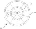
图1是根据本申请一些实施例所示的消融导管的应用场景示意图。在一些实施例中,如图1所示,消融导管100可以置于肺静脉口10处,以用于对肺静脉口10处的病变组织进行消融和/或标测。在一些实施例中,消融导管100可以用于对其他部位(如气管、支气管、肠道、胆囊、心脏等)的病变组织进行消融和/或标测。FIG. 1 is a schematic diagram of an application scenario of an ablation catheter according to some embodiments of the present application. In some embodiments, as shown in FIG. 1 , an
图2是根据本申请一些实施例所示的消融导管的结构示意图。在一些实施例中,如图1-2所示,消融导管100可以包括至少一个支撑杆,支撑杆上设有多个电极。在一些实施例中,电极可以为环形电极。例如,电极可以为薄片状环形电极。在一些实施例中,电极的材料可以包括银、氯化银、铂金、金、铜、钼或不锈钢中的一种或多种。在一些实施例中,环形电极可以通过焊接、卡接、粘接或热熔接等方式设置在支撑杆上。FIG. 2 is a schematic structural diagram of an ablation catheter according to some embodiments of the present application. In some embodiments, as shown in FIGS. 1-2, the
在一些实施例中,消融导管100可以包括第一支撑杆130和第二支撑杆140,第一支撑杆130和第二支撑杆140上可以设有多个电极。在一些实施例中,第一支撑杆130和第二支撑杆140可以为直线形状、弧形、环形等。在一些实施例中,消融导管100的至少一个支撑杆为环形支撑杆。在图1-2所示的实施例中,第一支撑杆130和第二支撑杆140可以均为环形支撑杆。通过将支撑杆设置为环形支撑杆,能够使得支撑杆(及其上的电极)更好的贴靠组织管腔,从而更好的对组织管腔上的病灶进行消融和/或标测。通过将消融导管100设置为双放电环结构(即第一支撑杆130和第二支撑杆140均为环形支撑杆),可以使得消融导管100对组织管腔的贴靠更牢固,且能够使得消融导管100具有更高的电场强度和更可控的消融范围,同时能够增加消融的能量密度以及标测密度。In some embodiments, the
在一些实施例中,第一支撑杆130和第二支撑杆140均为环形支撑杆,且第一支撑杆130形成的平面与第二支撑杆140形成的平面相互平行。在一些实施例中,环形的第一支撑杆130和第二支撑杆140同轴设置,即环形的第一支撑杆130的中心轴线与环形的第二支撑杆140的中心轴线重合。通过将环形的第一支撑杆130和第二支撑杆140设置为平行和/或同轴,能够便于第一支撑杆130和第二支撑杆140上电极相互对应。在一些实施例中,第一支撑杆130和第二支撑杆140上可以均设有多个电极。在一些实施例中,如图1-2所示,设置在第一支撑杆130上的电极与设置在第二支撑杆140上的电极可以一一对应。In some embodiments, the
在一些实施例中,第一支撑杆130上的多个电极具有相同的极性(如均为正极),第二支撑杆140上的多个电极也具有相同的极性(如均为负极),且第一支撑杆130上的电极与第二支撑杆140上的电极的极性相反。例如,第一支撑杆130上的多个电极均与能量发生器的正极连接,第二支撑杆140上的多个电极均与能量发生器的负极连接。正电极和负电极之间可以通过组织(如心肌组织)形成放电回路,从而在正负电极之间形成脉冲电场,利用脉冲电场对组织细胞(如心肌细胞)放电能够实现对组织(如心肌组织)的脉冲场消融。在一些实施例中,正负极之间的电压差的范围可以为500V到30000V。在一些实施例中,一次消融的放电时间范围可以:200纳秒到100微秒。在一些实施例中,能量发生器可以控制第一支撑杆130上的多个电极同时相对于第二支撑杆140上的多个电极放电,从而在第一支撑杆130和第二支撑杆140之间形成脉冲电场。通过将第一支撑杆130上的电极与第二支撑杆140上的电极一一对应设置,能够使得第一支撑杆130和第二支撑杆140之间形成的脉冲电场更加均匀。In some embodiments, multiple electrodes on the
在一些实施例中,第一支撑杆130和第二支撑杆140上的多个电极可以分别通过单独的导线与脉冲场能量发生器的电极输出端连接。例如,第一支撑杆130上的多个电极可以分别通过单独的导线与能量发生器的多个正极输出端连接;第二支撑杆140上的多个电极可以分别通过单独的导线与能量发生器的多个负极输出端连接。在一些实施例中,能量发生器可以控制第一支撑杆上的一个或多个电极相对于第二支撑杆上的一个或多个电极放电,从而在第一支撑杆130和第二支撑杆140之间形成局部脉冲电场,以对特定部位的病变组织进行消融。在一些实施例中,能量发生器可以控制第一支撑杆130上的一个电极相对于第二支撑杆140上对应的电极单独放电(即其余的电极均不同时放电),从而保证电场能量在单次放电中高度集中,以保证高的能量密度。在一些实施例中,如图2所示,第一支撑杆130上可以包括相邻的电极131和电极132;第二支撑杆140上可以包括相邻的电极141和电极142;其中,电极131与电极141相对应,电极132与电极142相对应。在一些实施例中,能量发生器可以控制电极131相对于电极141放电。在一些实施例中,能量发生器可以控制电极132相对于电极142放电。在一些实施例中,能量发生器可以依次控制每两个对应的电极放电。在一些实施例中,能量发生器可以同时控制电极131相对于电极141放电以及电极132相对于电极142放电。In some embodiments, the plurality of electrodes on the
在一些实施例中,能量发生器可以控制不同支撑杆上非对应的两个电极放电。在一些实施例中,能量发生器可以控制一个支撑杆上的电极相对于另一个支撑杆上与该电极对应的电极的相邻电极放电。例如,如图2所示,第一支撑杆130上的电极131与第二支撑杆140上的电极142并不对应(电极142为与电极131对应的电极141的相邻电极),能量发生器可以控制电极131相对于电极142放电(或电极142相对于电极131放电)。通过控制不同支撑杆上非对应的两个电极放电,可以配置出特定形状的脉冲电场,使得消融导管100能够更具针对性的对特定的病变组织进行消融。In some embodiments, the energy generator may control the discharge of two non-corresponding electrodes on different support rods. In some embodiments, the energy generator can control the discharge of an electrode on one support rod relative to an adjacent electrode of an electrode corresponding to that electrode on another support rod. For example, as shown in FIG. 2, the
在一些实施例中,第一支撑杆130上的多个电极间隔布置,第二支撑杆140上的多个电极间隔布置。在一些实施例中,同一个支撑杆(如第一支撑杆130或第二支撑杆140)上的多个电极之间(如相邻电极之间)能够形成脉冲电场,以用于对电极之间的区域进行消融。在一些实施例中,同一个支撑杆上的相邻电极的极性相反(如分别连接能量发生器的正极和负极),从而能够在同一个支撑杆上的相邻电极之间形成脉冲电场。In some embodiments, the plurality of electrodes on the
在一些实施例中,第一支撑杆130上的电极等间距分布,且第二支撑杆140上的电极等间距分布。具体的,第一支撑杆130上任意两个相邻电极相对于第一支撑杆130环中心的夹角相等,第二支撑杆140上任意两个相邻电极相对于第二支撑杆140环中心的夹角相等。通过将支撑杆上的电极设置为等间距分布,能够使得同一支撑杆上相邻电极之间形成的电场和/或不同支撑杆上对应电极之间形成的电场分布更加均匀,从而使得消融导管100更便于操控。在一些实施例中,任意两个相邻电极之间的间距L为10~15mm。在一些实施例中,第一支撑杆130和/或第二支撑杆140的环形直径可以与组织管腔(如肺静脉口)的直径相同或接近。在一些实施例中,第一支撑杆130和/或第二支撑杆140上所设置的电极数量可以根据组织管腔的直径以及相邻电极之间的间距L来确定。例如,设第一支撑杆130和/或第二支撑杆140上的电极数量为n,通过图像识别到的肺静脉口的直径为d,则可以通过公式n=π*d/L来确定第一支撑杆130和/或第二支撑杆140上所优选设置的电极数量。在一些实施例中,可以根据待消融的组织管腔的不同(如不同的直径)对应设置第一支撑杆130和/或第二支撑杆140的尺寸(如环形直径)。在一些实施例中,可以根据待消融的组织管腔的不同(如不同的直径)对应设置第一支撑杆130和/或第二支撑杆140上的电极数量。In some embodiments, the electrodes on the
在一些实施例中,消融导管100的支撑杆上设置的多个电极可以包括标测电极和消融电极,以分别用于对组织进行标测和消融。In some embodiments, the plurality of electrodes disposed on the support rod of the
在一些实施例中,多个电极中的每一个电极既能够作为标测电极,又能够作为消融电极。在一些实施例中,多个电极中的每一个电极可以分别通过导线与能量发生器连接,能量发生器不仅能够为电极提供脉冲电压,同时还能够获得电极之间标测到的电位信号。在一些实施例中,多个电极中的每一个电极可以分别通过导线与标测装置连接,标测装置能够获得电极之间标测到的电位信号。在一些实施例中,标测装置与能量发生器可以为同一装置也可以为不同的装置。通过将电极既作为标测电极又作为消融电极,消融设备能够在进行消融放电之后立刻进行原位标测,从而及时把握消融进度、获知消融结果。在一些实施例中,一旦标测电极检测到与病灶对应的电位信号消失,能量发生器即可控制消融电极停止放电,以避免消融能量的过度释放,有效保护可靠组织,避免医疗事故。在一些实施例中,标测装置可以控制第一支撑杆130和第二支撑杆140上的对应电极进行标测。在一些实施例中,标测装置可以控制一个支撑杆上的电极和另一个支撑杆上与该电极对应的电极的相邻电极进行标测。在一些实施例中,如图2所示,第一支撑杆130上可以包括相邻的电极131和电极132;第二支撑杆140上可以包括相邻的电极141和电极142;其中,电极131与电极141相对应,电极132与电极142相对应。电极131、132、141和142均可以作为消融电极。在一些实施例中,标测装置可以依次控制电极132和142进行标测、电极142和131进行标测以及电极131和141进行标测,从而形成Z字形标测模式。在一些实施例中,标测装置可以按照Z字形标测的方式标测对全圆周上的各组电极进行标测。通过Z字形标测的形式,能够有效提升标测密度,进而提升对病变组织标测的准确性。In some embodiments, each of the plurality of electrodes can function as both a mapping electrode and an ablation electrode. In some embodiments, each electrode of the plurality of electrodes can be connected to an energy generator through a wire respectively, and the energy generator can not only provide a pulse voltage to the electrodes, but also obtain potential signals mapped between the electrodes. In some embodiments, each of the plurality of electrodes may be connected to a mapping device through a wire, and the mapping device can obtain potential signals mapped between the electrodes. In some embodiments, the mapping device and the energy generator may be the same device or different devices. By using the electrode as both a mapping electrode and an ablation electrode, the ablation device can perform in-situ mapping immediately after the ablation discharge, so as to grasp the ablation progress and know the ablation result in time. In some embodiments, once the mapping electrode detects that the potential signal corresponding to the lesion disappears, the energy generator can control the ablation electrode to stop discharging, so as to avoid excessive release of ablation energy, effectively protect reliable tissue, and avoid medical accidents. In some embodiments, the mapping device may control the corresponding electrodes on the
在一些实施例中,标测电极与消融电极可以在同一支撑杆(如第一支撑杆130和/或第二支撑杆140)上间隔布置。在一些实施例中,消融电极可以通过导线与能量发生器连接,标测电极可以通过导线与标测装置连接。在一些实施例中,标测装置与能量发生器可以为同一装置也可以为不同的装置。在一些实施例中,消融电极用于对组织进行消融的同时,标测电极可以用于对组织进行标测。通过将标测电极与消融电极间隔布置,消融设备能够同时对同一部位的组织进行消融和标测,从而实时监控病灶的消融情况。在一些实施例中,在标测电极与消融电极间隔布置的情况下,消融设备可以交替对组织进行消融和标测。例如,消融设备可以先控制消融电极对组织进行消融,再控制标测电极对消融放电后的组织进行标测。在一些实施例中,如图2所示,第一支撑杆130上可以包括间隔设置的5个电极(电极131、电极132、电极133、电极134和电极135),其中,电极131、133和135可以为消融电极(例如,电极131和135为正极,电极133为负极),电极132和134可以为标测电极。在一些实施例中,电极131、133和135在对组织进行消融放电的同时,电极132和134可以用于对组织进行标测。在一些实施例中,消融设备可以先控制电极131、133和135对组织进行消融,再控制电极132和134对组织进行标测。In some embodiments, the mapping electrodes and the ablation electrodes may be spaced apart on the same support rod (eg, the
在一些替代性实施例中,其中一个支撑杆上可以均设置标测电极,另一个支撑杆上可以均设置消融电极。例如,第一支撑杆130上的电极可以均为标测电极,第二支撑杆140上的电极可以均为消融电极。在一些实施例中,可以先利用第一支撑杆130对组织的一周进行标测,再根据标测结果,利用第二支撑杆140上的消融电极对组织(或组织上的病灶区域)进行消融。在一些实施例中,当消融完成后,可以通过第一支撑杆130的标测电极对消融后的组织进一步进行标测。In some alternative embodiments, mapping electrodes may be provided on one of the support rods, and ablation electrodes may be provided on both of the other support rods. For example, the electrodes on the
在一些实施例中,如图1-2所示,消融导管100可以包括内管120和外管110。第一支撑杆130和第二支撑杆140设置在内管120上。如图1-2所示,第一支撑杆130和第二支撑杆140可以设置在内管120的前端,其中,前端可以指远离手术操作者的一端。外管110套设在内管120外,内管120能够相对于外管110移动(如沿内管/外管的长度方向移动),以使得第一支撑杆130和第二支撑杆140能够收缩至外管110中,或者从外管110中伸出以形成环形支撑杆。在一些实施例中,外管110和内管120均为空心圆管状,外管110套设在内管120的外圆周上,内管120内部可以用于供导线和/或绳索(如弯曲度调节绳)通过。在一些实施例中,消融设备可以包括消融导管100和控制手柄(图中未示出),控制手柄能够用于控制内管120沿长度方向相对于外管110移动。内管120相对于外管110移动时,能够带动内管120上的第一支撑杆130和第二支撑杆140移动,从而控制第一支撑杆130和第二支撑杆140收缩至外管110中或者从外管110中伸出。In some embodiments, as shown in FIGS. 1-2 ,
在一些实施例中,第一支撑杆130和第二支撑杆140可以由绝缘材料制成,且制成后具有一定的弹性,并具有形状记忆能力。绝缘材料可以包括但不限于塑料(如高弹性尼龙材料等)、热塑性弹性体(如热塑性聚氨酯弹性体(TPU)、苯乙烯类热塑性弹性体(TPS)等)等。在一些实施例中,当第一支撑杆130和第二支撑杆140随着内管120的移动收缩至外管110内时,第一支撑杆130和第二支撑杆140可以呈长条状收缩至外管110内部,从而便于消融导管100输送进入人体内以及从人体内退出。在一些实施例中,当第一支撑杆130和第二支撑杆140从外管110中伸出时,由于材料的形状记忆能力可以自动形成环形支撑杆。In some embodiments, the
在一些实施例中,内管和/或外管可以由绝缘材料制成,且制成后的内管和外管均具有一定弹性,能够受力弯曲且不易弯折变形。在一些实施例中,内管120和/或外管110可以由高分子绝缘材料制成。高分子绝缘材料可以包括但不限于聚氨酯(PU)、聚乙烯(PE)、聚醚嵌段聚酰胺(PEBAX)、TPU、TPS等中的一种或多种的组合。在一些实施例中,内管120和外管110的材料可以相同或不同。在一些实施例中,第一支撑杆130和/或第二支撑杆140的材料可以与内管的材料相同或不同。在一些实施例中,例如,第一支撑杆130和/或第二支撑杆140可以通过焊接、卡接、粘接、热熔接、螺纹连接或一体成型等方式与内管120实现固连。In some embodiments, the inner tube and/or the outer tube may be made of insulating material, and the fabricated inner tube and outer tube have certain elasticity, can be bent under force and are not easily deformed. In some embodiments, the
在一些实施例中,第一支撑杆130和第二支撑杆140的直径可以为0.3~3mm(如0.3mm、0.5mm、0.7mm、1mm、2mm、3mm等)。第一支撑杆130和第二支撑杆140的直径可以相同或不同。在一些实施例中,内管120的直径可以等于或略大于第一支撑杆130和第二支撑杆140的直径。在一些实施例中,外管110内壁的直径可以略大于内管120的直径。例如,外管110内壁的直径可以为0.4~3.5mm(如0.4mm、0.6mm、0.8mm、1.2mm、2.2mm、3.5mm等)。在一些实施例中,当第一支撑杆130和第二支撑杆140形成环形支撑杆时,其环形的最大直径可以为5~40mm(如5mm、8mm、15mm、25mm、40mm等)。在一些实施例中,内管120和外管110的尺寸,以及第一支撑杆130和第二支撑杆140的尺寸可以根据消融部位、病变组织类型、患者年龄等进行适应性调整,本申请对此不做限制。In some embodiments, the diameters of the
在一些实施例中,如图1-2所示,第一支撑杆130可以通过第一连接杆150与内管120连接,第二支撑杆140可以通过第二连接杆160与内管120连接。通过设置第一连接杆150与第二连接杆160,能够使得第一支撑杆130和第二支撑杆140更易于形成环形形状。通过将第一支撑杆130和第二支撑杆140独立的设置在内管120上,能够便于对第一支撑杆130和第二支撑杆140单独控制,以适应更多的消融场景。在一些实施例中,第一连接杆150和第二连接杆160的材料可以为塑料(如高弹性尼龙材料等)、热塑性弹性体(如TPU、TPS等)等。在一些实施例中,第一连接杆150和第二连接杆160的材料可以与第一支撑杆130和第二支撑杆140的材料相同或不同。在一些实施例中,第一连接杆150和第二连接杆160的一端可以通过粘接、热熔接或一体成型等方式分别与第一支撑杆130和第二支撑杆140的一端固连。第一连接杆150和第二连接杆160的另一端可以通过粘接、热熔接或一体成型等方式分别与内管120固连。在一些实施例中,第一支撑杆130和第二支撑杆140的另一端可以为自由端,呈自由悬空状态。通过将支撑杆(如第一支撑杆130或第二支撑杆140)与连接杆(如第一连接杆150或第二连接杆160)依次首尾连接并连接至内管120上,能够便于支撑杆和连接杆呈长条状收缩至外管110内部,减小外管110的尺寸。在一些替代性实施例中,第一支撑杆130和第二支撑杆140可以直接与内管120连接。In some embodiments, as shown in FIGS. 1-2 , the
在一些实施例中,消融导管的第一支撑杆的环形直径与第二支撑杆的环形直径相同。在一些实施例中,消融导管的第一支撑杆的环形直径与第二支撑杆的环形直径不同。通过将第一支撑杆的环形直径设置为与第二支撑杆的环形直径不同,可以使得消融导管能够更好的适用于变径的组织管腔的消融和/或标测。In some embodiments, the annular diameter of the first support rod of the ablation catheter is the same as the annular diameter of the second support rod. In some embodiments, the annular diameter of the first support rod of the ablation catheter is different from the annular diameter of the second support rod. By setting the annular diameter of the first support rod to be different from the annular diameter of the second support rod, the ablation catheter can be better suited for ablation and/or mapping of tissue lumens with reduced diameters.
图3是根据本申请另一实施例所示的消融导管的结构示意图;图4是根据本申请另一实施例所示的消融导管的侧视图;图5是根据本申请另一实施例所示的消融导管的俯视图。FIG. 3 is a schematic structural diagram of an ablation catheter according to another embodiment of the present application; FIG. 4 is a side view of an ablation catheter according to another embodiment of the present application; FIG. 5 is a schematic diagram of another embodiment of the present application. Top view of the ablation catheter.
在一些实施例中,如图3-5所示,消融导管200可以包括第一支撑杆230和第二支撑杆240;第一支撑杆230相对于第二支撑杆240更靠近消融导管200的前端。在一些实施例中,第一支撑杆230的环形直径可以小于第二支撑杆240的环形直径,以便于变径的组织管腔的消融和/或标测。在一些实施例中,第一支撑杆230和第二支撑杆240的环形直径的尺寸可以根据消融部位、病变组织类型、患者年龄等进行适应性调整。在一些实施例中,如图4所示,第一支撑杆230的环形与第二支撑杆240的环形具有相互平行的端面。在一些实施例中,如图5所示,第一支撑杆230的环形与第二支撑杆240的环形具有相同的中心轴线。通过将环形的第一支撑杆130和第二支撑杆140设置为平行和/或同轴,能够便于第一支撑杆130和第二支撑杆140上电极相互对应,使得消融区界限更加清晰,对病变组织的消融更加均匀,同时还能便于实施消融手术的医生对消融导管的操控。In some embodiments, as shown in FIGS. 3-5 , the
在一些实施例中,参见图3,第一支撑杆230和第二支撑杆240可以通过第三连接杆270首尾连接。通过设置第三连接杆270,能够使得第一支撑杆230和第二支撑杆240更易于形成环形形状。在一些实施例中,第三连接杆270的材料可以为塑料(如高弹性尼龙材料等)、热塑性弹性体(如TPU、TPS等)等。在一些实施例中,第三连接杆270材料可以与第一支撑杆230和第二支撑杆240的材料相同或不同。在一些实施例中,第一支撑杆230的一端可以与第三连接杆270的一端连接,第一支撑杆230的另一端可以为自由端。第三连接杆270的另一端可以与第二支撑杆240连接,第二支撑杆240的另一端可以通过第二连接杆260与内管220固连。通过将第一支撑杆230、第三连接杆270、第二支撑杆240和第二连接杆260首尾连接形成长条状结构,能够便于支撑杆和连接杆顺利收缩至外管210内,减小外管210的尺寸,从而便于手术前后导管的输送和退出。In some embodiments, referring to FIG. 3 , the
在一些实施例中,如图3-5所示,设置在第一支撑杆230上的电极与设置在第二支撑杆240上的电极可以一一对应。在一些实施例中,第一支撑杆230上的电极等间距分布,且第二支撑杆240上的电极等间距分布。具体的,第一支撑杆230上任意两个相邻电极相对于第一支撑杆230环中心的夹角相等,第二支撑杆240上任意两个相邻电极相对于第二支撑杆240环中心的夹角相等。在一些实施例中,第一支撑杆130上可以包括相邻的电极231和电极232;第二支撑杆240上可以包括相邻的电极241和电极242;其中,电极231与电极241相对应,电极232与电极242相对应。在一些实施例中,关于消融导管200及其消融/标测过程的更多信息可以参见图1-2及其相关描述。In some embodiments, as shown in FIGS. 3-5 , the electrodes disposed on the
图6是根据本申请再一实施例所示的消融导管的结构示意图。FIG. 6 is a schematic structural diagram of an ablation catheter according to still another embodiment of the present application.
在一些实施例中,设置在一个支撑杆上的两个或多个电极可以与设置在另一个支撑杆上的一个电极相对应。在一些实施例中,如图6所示,在消融导管300中,设置在第一支撑杆330上的两个相邻电极(如电极331和电极332)可以与设置在第二支撑杆340上的一个电极(如电极341)相对应。第一支撑杆330上的两个相邻电极(如电极331和电极332)能够与对应的第二支撑杆340上的一个电极(如电极341)形成脉冲电场。具体的,第一支撑杆330上的两个相邻电极331和332可以分别通过单独的导线与外部的能量发生器的正极相连,第二支撑杆340上的电极341可以通过单独的导线与外部的能量发生器的负极相连。能量发生器能够控制电极331和332同时相对于电极341放电,以在电极331和341之间以及电极332和341之间形成两条放电回路,从而在电极331、332与电极341之间形成脉冲电场。通过一个支撑杆上的两个或多个电极与另一个支撑杆上的一个电极形成脉冲电场,能够配置出特定的电场范围,以适用于对特定区域(如特定形状)的病变组织进行消融。例如,通过一个支撑杆上的两个电极与另一个支撑杆上的一个电极形成脉冲电场,能够适用于近似三角形区域的病变组织的消融。In some embodiments, two or more electrodes provided on one support rod may correspond to one electrode provided on another support rod. In some embodiments, as shown in FIG. 6 , in the
在一些实施例中,如图6所示,第二支撑杆340上的电极341可以与第一支撑杆330上两个相邻电极331和332的中间点相对应。具体的,第一支撑杆330和第二支撑杆340可以是两个相互平行且同轴的环形支撑杆,电极341与第一支撑杆330上两个相邻电极331和332的中间点的连线可以与第一支撑杆330所形成的平面垂直。通过将第二支撑杆340上的电极341设置为与第一支撑杆330上两个相邻电极(电极331和332)的中间点相对应,可以使得第一支撑杆330上的两个相邻电极与电极341的距离相同,从而更容易对电极331、332与电极341之间形成的脉冲电场进行控制。In some embodiments, as shown in FIG. 6 , the
在一些实施例中,可以在第一支撑杆330上设置三个及以上电极(如3个、4个、5个电极等)与第二支撑杆上的一个电极相对应,从而获得不同的电场范围,以适用于不同区域(如不同形状)的病变组织的消融。在一些实施例中,与第二支撑杆上的一个电极相对应的第一支撑杆330上的电极数量的选择,可以根据消融部位、病变组织类型、病变组织形状等进行适应性调整,也可以在消融手术进行中根据消融进度/标测结果进行调整。In some embodiments, three or more electrodes (eg, 3, 4, 5 electrodes, etc.) may be arranged on the
在一些实施例中,第一支撑杆和第二支撑杆上设置的多个电极中,可以包括不同的第一电极和第二电极。在一些实施例中,“第一电极”或“第二电极”可以用于泛指某一种类的电极。在一些实施例中,“第一电极”或“第二电极”可以用于泛指某一个具体的电极。在一些实施例中,第一电极和第二电极的阻值不同。在一些实施例中,第一电极与第二电极的材料和/或尺寸不同,以使得第一电极与第二电极的阻值不同。在一些实施例中,第一电极和第二电极可以设置在同一个支撑杆上。例如,第一电极和第二电极可以为设置在同一个支撑杆上的相邻电极。在一些实施例中,第一电极和第二电极可以设置在不同的支撑杆上。例如,第一电极和第二电极可以分别设置在第一支撑杆和第二支撑杆上,且第一电极与第二电极对应。在一些实施例中,第一电极和第二电极之间能够形成消融电场。在一些实施例中,两个或多个第一电极之间能够形成消融电场;两个或多个第二电极之间能够形成消融电场。通过设置不同的第一电极和第二电极,可以使得消融导管能够形成特定范围、形状或强度的消融电场(如非匀强电场),从而适用于不同病变组织的消融。In some embodiments, the plurality of electrodes disposed on the first support rod and the second support rod may include different first electrodes and second electrodes. In some embodiments, "first electrode" or "second electrode" may be used to refer generally to a certain type of electrode. In some embodiments, "first electrode" or "second electrode" may be used to refer to a specific electrode in general. In some embodiments, the resistance values of the first electrode and the second electrode are different. In some embodiments, the materials and/or dimensions of the first electrode and the second electrode are different, so that the resistance values of the first electrode and the second electrode are different. In some embodiments, the first electrode and the second electrode may be disposed on the same support rod. For example, the first electrode and the second electrode may be adjacent electrodes disposed on the same support rod. In some embodiments, the first electrode and the second electrode may be disposed on different support rods. For example, the first electrode and the second electrode may be respectively disposed on the first support rod and the second support rod, and the first electrode corresponds to the second electrode. In some embodiments, an ablation electric field can be formed between the first electrode and the second electrode. In some embodiments, an ablation electric field can be formed between two or more first electrodes; an ablation electric field can be formed between two or more second electrodes. By setting different first electrodes and second electrodes, the ablation catheter can form an ablation electric field with a specific range, shape or intensity (eg, non-uniform electric field), so as to be suitable for ablation of different diseased tissues.
在一些实施例中,第一电极与第二电极的材料可以不同。在一些实施例中,第一电极的材料可以包括但不限于:银、氯化银、铂金、金、铜、钼或不锈钢等中的一种或多种的组合。在一些实施例中,第二电极的材料可以包括但不限于:银、氯化银、铂金、金、铜、钼或不锈钢等中的一种或多种的组合。In some embodiments, the materials of the first electrode and the second electrode may be different. In some embodiments, the material of the first electrode may include, but is not limited to, a combination of one or more of silver, silver chloride, platinum, gold, copper, molybdenum, stainless steel, and the like. In some embodiments, the material of the second electrode may include, but is not limited to, a combination of one or more of silver, silver chloride, platinum, gold, copper, molybdenum, or stainless steel.
在一些实施例中,第一电极和第二电极可以设置在同一个支撑杆上。在一些实施例中,一个支撑杆上可以包含一对第一电极和一对第二电极。在一些实施例中,如图2所示,第一支撑杆130上的电极131和电极132可以为第一电极,电极133和电极134可以为第二电极。例如,电极131和电极132的材料可以为钼;电极133和电极134的材料可以为不锈钢。在一些实施例中,电极131和电极132之间能够形成脉冲电场;电极133和电极134之间能够形成脉冲电场。由于第一电极与第二电极的材料不同,则第一电极之间(如电极131和电极132之间)所形成的电场与第二电极之间(如电极133和电极134之间)所形成的电场不同(如电场强度不同),从而使得同一个支撑杆(如第一支撑杆130)上的不同电极之间便能够形成不同的电场,使得该支撑杆能够适用于对更多类型的病变组织进行消融。In some embodiments, the first electrode and the second electrode may be disposed on the same support rod. In some embodiments, a support rod may contain a pair of first electrodes and a pair of second electrodes. In some embodiments, as shown in FIG. 2 , the
在一些实施例中,第一电极和第二电极可以分别对应的设置在不同的支撑杆上。在一些实施例中,如图2所示,第一支撑杆130上的电极131可以为第一电极,电极132可以为第二电极;与之对应的,第二支撑杆140上的电极141可以为第一电极,电极142可以为第二电极。例如,电极131和电极141的材料可以为铂金;电极132和电极142的材料可以为不锈钢。在一些实施例中,电极131和电极141之间能够形成脉冲电场;电极132和电极142之间能够形成脉冲电场。由于第一电极与第二电极的材料不同,则第一电极之间(如电极131和电极141之间)所形成的电场与第二电极之间(如电极132和电极142之间)所形成的电场不同(如电场强度不同),从而使得两个支撑杆上的不同的对应电极之间能够形成不同的电场,使得消融导管能够适用于对更多类型的病变组织进行消融。In some embodiments, the first electrode and the second electrode may be correspondingly disposed on different support rods, respectively. In some embodiments, as shown in FIG. 2 , the
在一些实施例中,不同材料的电极可以适用于对不同的病变组织进行消融。在一些实施例中,以两电极之前测得的病变组织的阻抗值为例进行区分,不同阻抗值的病变组织可以优选采用不同材料的电极进行消融。例如,当病变组织的阻抗值低于50欧姆时可以选用不锈钢材料的电极;当病变组织的阻抗值为50至200欧姆时可以选用钼材料的电极;当病变组织的阻抗值为200至400欧姆时可以选用铂金材料的电极,当病变组织的阻抗值为400至600欧姆时可以选用银/氯化银材料的电极。在一些实施例中,对于分别由银/氯化银、铂金、钼和不锈钢材料制成的电极而言,电极的导电性能由强变弱,电极的阻值由小变大。由于电极的材料不同,电极的阻值不同,在外部条件(如给电极施加的外部电压)相同的情况下,则电极之间所形成的电场不同,从而使得不同材料的电极能够适用于对不同的病变组织进行消融。In some embodiments, electrodes of different materials may be suitable for ablation of different diseased tissues. In some embodiments, the impedance value of the diseased tissue measured before the two electrodes is used as an example to distinguish, and the diseased tissue with different impedance values may preferably be ablated by using electrodes of different materials. For example, when the impedance value of the diseased tissue is lower than 50 ohms, an electrode made of stainless steel can be used; when the impedance value of the diseased tissue is 50 to 200 ohms, an electrode made of molybdenum material can be used; when the impedance value of the diseased tissue is 200 to 400 ohms Electrodes made of platinum materials can be used when the disease is present, and electrodes made of silver/silver chloride materials can be used when the impedance of the diseased tissue is 400 to 600 ohms. In some embodiments, for electrodes made of silver/silver chloride, platinum, molybdenum and stainless steel, respectively, the electrical conductivity of the electrodes changes from strong to weak, and the resistance of the electrodes changes from small to large. Due to the different materials of the electrodes and the different resistance values of the electrodes, under the same external conditions (such as the external voltage applied to the electrodes), the electric fields formed between the electrodes are different, so that electrodes of different materials can be applied to different of diseased tissue for ablation.
在一些实施例中,第一电极和第二电极的尺寸可以不同。在一些实施例中,第一电极和第二电极的电极长度可以不同。在一些实施例中,电极可以是设置在支撑杆上的环电极。例如,电极可以由薄片状的金属首尾拼接呈环形粘贴在支撑杆的外圆周上。则电极长度可以指环电极沿支撑杆延伸方向的距离。在一些实施例中,电极长度可以为1-8mm。优选的,电极长度可以为3-5mm。在一些实施例中,不同电极长度的第一电极和第二电极可以设置在同一个支撑杆上。例如,一个支撑杆上可以包含一对第一电极和一对第二电极。由于第一电极与第二电极的电极长度不同,会使第一电极与第二电极的阻值不同,则第一电极之间所形成的电场与第二电极之间所形成的电场不同(如电场强度、电场形状不同),从而使得该支撑杆能够适用于对不同类型的病变组织进行消融。在一些实施例中,第一电极和第二电极可以分别对应的设置在不同的支撑杆上,使得两个支撑杆上的不同的对应电极之间能够形成不同的电场,进而使得消融导管能够适用于对更多类型的病变组织进行消融。In some embodiments, the dimensions of the first electrode and the second electrode may be different. In some embodiments, the electrode lengths of the first electrode and the second electrode may be different. In some embodiments, the electrodes may be ring electrodes disposed on the support rods. For example, the electrodes can be attached to the outer circumference of the support rod by splicing sheet metal end to end in a ring shape. Then the electrode length may refer to the distance of the ring electrode along the extending direction of the support rod. In some embodiments, the electrode length may be 1-8 mm. Preferably, the electrode length may be 3-5mm. In some embodiments, the first electrode and the second electrode of different electrode lengths may be disposed on the same support rod. For example, a support rod may contain a pair of first electrodes and a pair of second electrodes. Since the electrode lengths of the first electrode and the second electrode are different, the resistance values of the first electrode and the second electrode will be different, and the electric field formed between the first electrodes and the electric field formed between the second electrodes are different (such as The electric field strength and electric field shape are different), so that the support rod can be suitable for ablation of different types of diseased tissue. In some embodiments, the first electrode and the second electrode may be respectively disposed on different support rods, so that different electric fields can be formed between the different corresponding electrodes on the two support rods, so that the ablation catheter can be applied for ablation of more types of diseased tissue.
在一些实施例中,第一电极和第二电极的材料和尺寸可以均不同,以使得第一电极与第二电极的阻值不同。第一电极之间所形成的电场与第二电极之间所形成的电场不同(如电场强度、电场形状不同),从而使得消融导管能够适用于对不同类型的病变组织进行消融。In some embodiments, the materials and dimensions of the first electrode and the second electrode may be different, so that the resistance values of the first electrode and the second electrode are different. The electric field formed between the first electrodes and the electric field formed between the second electrodes are different (eg, electric field strength, electric field shape are different), so that the ablation catheter can be suitable for ablation of different types of diseased tissue.
图7是根据本申请一些实施例所示的消融导管及其放电方式的示意图。FIG. 7 is a schematic diagram of an ablation catheter and a discharge manner thereof according to some embodiments of the present application.
在一些实施例中,能量发生器能够控制消融导管上的多个电极对多个电极同时放电,以增加电场范围,提升消融效率。在一些实施例中,如图7所示,消融导管400包括第一支撑杆430和第二支撑杆440。第一支撑杆430上设置有相邻的电极431、432、433、434和435。第二支撑杆440上设置有相对应的相邻的电极441、442、443、444和445。在一些实施例中,能量发生器能够控制第一支撑杆430上三个相邻的电极(如电极431、432和433)对第二支撑杆440上三个对应的电极(如电极441、442和443)放电。在一些实施例中,能量发生器能够控制第一支撑杆430上五个相邻的电极(如电极431、432、433、434和435)对第二支撑杆440上五个对应的电极(如电极441、442、443、444和445)放电。In some embodiments, the energy generator can control multiple electrodes on the ablation catheter to discharge multiple electrodes at the same time, so as to increase the electric field range and improve the ablation efficiency. In some embodiments, as shown in FIG. 7 , the
在一些实施例中,第一支撑杆430上可以包括相邻且等间距设置的第一电极(如电极431)、第二电极(如电极432)以及第三电极(如电极433),第二电极设置在第一电极和第三电极之间。在一些实施例中,第一电极和第三电极的阻值相等,且第二电极的阻值大于第一电极和第三电极的阻值。在一些实施例中,第二电极的材料和/或尺寸与第一电极和第三电极不同,以使得第二电极的阻值大于第一电极和第三电极的阻值。例如,第一电极和第三电极的材料为铂金材料,第二电极的材料为不锈钢材料。又例如,第一电极和第三电极的电极长度相等,第二电极的电极长度小于第一电极和第三电极。通过将第二电极的阻值设置得更大,能够使得该三个电极(如电极431、432和433)相对于另外三个电极(如电极441、442和443)放电时,所形成的电场更均匀。在一些实施例中,在多个电极对多个电极同时放电时,由于电场具有边缘效应,边上的电极(如电极431和441,或者电极433和443)所形成的电场会对中间电极之间的区域产生影响,若此时中间的电极(如电极432和442)产生的电场与边上电极产生的电场相同,则会导致整体形成的电场不够均匀(如中间区域的电场强度更大)。通过将中间电极(如第二电极)的阻值设置得更大,能够使得中间电极所形成的电场强度减小,从而使得整体形成的电场更加均匀。In some embodiments, the
在一些实施例中,第二支撑杆440上设有与第一电极(如电极431)、第二电极(如电极432)以及第三电极(如电极433)分别对应的第四电极(如电极441)、第五电极(如电极442)和第六电极(如电极443)。在一些实施例中,第一电极、第二电极以及第三电极可以与能量发生器的正极连接;第四电极、第五电极和第六电极可以与能量发生器的负极连接;能量发生器能够控制第一电极、第二电极以及第三电极同时对第四电极、第五电极和第六电极放电。在一些实施例中,第四电极、第五电极和第六电极的阻值可以相等。在一些实施例中,第四电极、第五电极和第六电极的阻值可以与第一电极、第二电极以及第三电极对应设置。例如,第四电极和第六电极的阻值相等,且第五电极的阻值大于第四电极和第六电极的阻值。通过将第四电极、第五电极和第六电极的阻值与第一电极、第二电极以及第三电极对应设置,能够使得电场强度更均匀。In some embodiments, the
在一些实施例中,消融导管上的多个电极对多个电极同时放电还可以包括:4个电极对4个电极放电、5个电极对5个电极放电、6个电极对6个电极放电等。在一些实施例中,多个电极的中间电极的阻值可以大于边上电极的阻值。在一些实施例中,多个电极的阻值可以由中间向两边依次递减。通过这样的电极设置,可以使得多个电极对多个电极同时放电时所形成的电场更匀称。在一些实施例中,如图7所示,第一支撑杆430上相邻且等间距依次设置电极431、432、433、434和435。第二支撑杆440上相邻且等间距依次设置电极441、442、443、444和445。电极431、432、433、434和435与电极441、442、443、444和445一一对应设置。在一些实施例中,电极431、432、433、434和435可以与能量发生器的正极连接;电极441、442、443、444和445可以与能量发生器的负极连接;能量发生器能够控制电极431、432、433、434和435同时对电极441、442、443、444和445放电。在一些实施例中,电极431、435、441和445的阻值相等,电极432、434、442和444的阻值相等且大于前者的阻值,电极433和443的阻值相等且大于前者的阻值。在一些实施例中,各电极之间的材料和/或尺寸不同,以使得各电极之间的阻值不同。例如,边上的电极431、435、441和445可以采用导电性能较好的银/氯化银材料,次中间的电极432、434、442和444可以采用导电性能次之的铂金材料,最中间的电极433和443可以采用导电性能相对较差的不锈钢材料。In some embodiments, the simultaneous discharge of multiple electrodes on the ablation catheter to multiple electrodes may further include: 4 electrodes to discharge 4 electrodes, 5 electrodes to discharge to 5 electrodes, 6 electrodes to discharge to 6 electrodes, etc. . In some embodiments, the resistance of the middle electrode of the plurality of electrodes may be greater than the resistance of the side electrodes. In some embodiments, the resistance values of the plurality of electrodes may decrease sequentially from the middle to the two sides. With such electrode arrangement, the electric field formed when multiple electrodes discharge simultaneously to multiple electrodes can be made more uniform. In some embodiments, as shown in FIG. 7 ,
在一些实施例中,能量发生器能够控制消融导管上的多个电极对多个电极同时放电,且不同对应电极之间的电压差不完全相同。例如,能量发生器能够控制第一支撑杆430上三个相邻的电极(如电极431、432和433)对第二支撑杆440上三个对应的电极(如电极441、442和443)放电;电极432和442之间的电压差小于电极431和441之间以及电极433和443之间的电压差。通过控制中间的对应电极之间的电压差更小,能够使得中间电极所形成的电场强度减小,从而使得整体形成的电场更加均匀。在一些实施例中,相比于利用电压差控制多个电极对多个电极放电以实现放电时电场更均匀,通过电极的自身特性(如材料和/或尺寸)的区别来实现电场更均匀能够有效提升控制便捷性,降低对医务人员的要求。In some embodiments, the energy generator can control multiple electrodes on the ablation catheter to discharge multiple electrodes simultaneously, and the voltage differences between different corresponding electrodes are not identical. For example, the energy generator can control three adjacent electrodes (eg,
在一些实施例中,第一支撑杆(如第一支撑杆130)上可以包括第一电极(如电极131),第二支撑杆(如第二支撑杆140)上可以包括第二电极(如电极141),第一电极与第二电极对应。在一些实施例中,第一电极与第二电极的构造不同。电极的构造可以理解为电极的组成形式。在一些实施例中,第一电极(如电极131)和第二电极(如电极141)之间能够形成脉冲电场。通过将第一电极与第二电极的构造设置为不同,可以使得第一电极和第二电极之间能够产生特定的电场形式,从而能够适用于对特定的病变组织进行消融。In some embodiments, the first support rod (eg, the first support rod 130 ) may include a first electrode (eg, the electrode 131 ), and the second support rod (eg, the second support rod 140 ) may include a second electrode (eg, the second support rod 140 ) electrode 141), the first electrode corresponds to the second electrode. In some embodiments, the configuration of the first electrode and the second electrode are different. The structure of the electrode can be understood as the composition form of the electrode. In some embodiments, a pulsed electric field can be formed between the first electrode (eg, electrode 131 ) and the second electrode (eg, electrode 141 ). By setting the structures of the first electrode and the second electrode to be different, a specific electric field form can be generated between the first electrode and the second electrode, so as to be suitable for ablation of a specific diseased tissue.
图8是根据本申请一些实施例所示的消融导管的电极结构示意图。图9是根据本申请一些实施例所示的消融导管的第一电极与第二电极相对应的结构示意图。FIG. 8 is a schematic diagram of an electrode structure of an ablation catheter according to some embodiments of the present application. FIG. 9 is a schematic structural diagram of the first electrode and the second electrode of the ablation catheter corresponding to some embodiments of the present application.
在一些实施例中,第一电极可以由多个(如两个或两个以上)子电极沿长度方向首尾拼接而成。在一些实施例中,相邻两个子电极的材料和/或尺寸不同;以使得相邻两个子电极的阻值不同。在一些实施例中,如图8所示,电极510可以为第一电极,电极510可以由4个子电极511首尾拼接而成。在一些实施例中,如图8所示,电极510的4个子电极511的尺寸(如子电极长度)可以相同,任意两个相邻子电极511的材料不同。在一些实施例中,电极510的4个子电极511的材料可以依次为氯化银、铂金、氯化银和铂金。在一些实施例中,电极510的4个子电极511的材料可以依次为氯化银、铂金、钼和不锈钢。在一些实施例中,多个子电极可以首尾相接并分别固设(如粘接)在支撑杆上,以形成第一电极。在一些实施例中,多个子电极可以首尾固连(如焊接、粘接等)以形成第一电极后再固设到支撑杆上。在一些实施例中,每个子电极可以分别通过单独的导线与外部的能量发生器连接。在一些实施例中,第一电极的多个子电极可以通过同一根导线与外部的能量发生器连接。例如,导线的一端可以通过贴片均匀的贴在四个子电极上。在一些实施例中,多个子电极之间相互连通,导线可以仅与其中的一个或部分子电极相连接。In some embodiments, the first electrode may be formed by splicing multiple (eg, two or more) sub-electrodes end to end along the length direction. In some embodiments, the materials and/or dimensions of two adjacent sub-electrodes are different; so that the resistance values of the two adjacent sub-electrodes are different. In some embodiments, as shown in FIG. 8 , the
在一些实施例中,如图9所示,电极520可以为第一电极,电极520可以由4个子电极521首尾拼接而成。在一些实施例中,如图9所示,电极520的4个子电极521中,任意两个相邻子电极521的尺寸(如子电极长度)可以不同。例如,4个子电极521的尺寸可以完全不同。又例如,如图9所示,相隔的子电极521的尺寸可以相同;4个子电极521可以包含长和短两种尺寸,长的子电极和短的子电极交替排列。在一些实施例中,4个子电极521可以采用同一种材料,从而4个子电极仅在尺寸上相互区别。在一些实施例中,4个子电极521的材料可以不完全相同。例如,长的子电极的材料可以为氯化银,短的子电极的材料可以为铂金。In some embodiments, as shown in FIG. 9 , the
在一些实施例中,与第一电极(如电极510或电极520)相对应的第二电极可以是一个整体的电极。第一电极的各个子电极能够分别相对于第二电极放电以形成脉冲电场。通过将第一电极的相邻两个子电极的材料和/或尺寸设置为不同,能够使得相邻两个子电极的阻值不同,从而使得各个子电极与第二电极所形成的脉冲电场不完全相同(如强度、形状和/或范围不同),进而在第一电极与第二电极之间能够形成不均匀的电场。在针对一些特殊的病变组织(如多种病变组织混合、不明确的病变组织等)进行消融时,不均匀电场的组织适用范围更大,消融效果更好。In some embodiments, the second electrode corresponding to the first electrode (eg,
在一些实施例中,与第一电极相对应的第二电极可以由多个子电极(如两个或两个以上)沿长度方向首尾拼接而成。在一些实施例中,第二电极的多个子电极中,相邻两个子电极的材料和/或尺寸不同,以使得相邻两个子电极的阻值不同。在一些实施例中,每个子电极可以分别通过单独的导线与外部的能量发生器连接。在一些实施例中,第二电极的多个子电极可以通过同一根导线与外部的能量发生器连接。在一些实施例中,多个子电极之间相互连通,导线可以仅与其中的一个或部分子电极相连接。在一些实施例中,第一电极的多个子电极可以通过导线与外部的能量发生器的正极相连,第二电极的多个子电极可以通过导线与外部的能量发生器的负极相连,从而能量发生器能够控制第一电极的多个子电极相对于第二电极的多个子电极放电。在一些实施例中,第一电极的子电极数量与第二电极的子电极数量相等。通过在第二电极上设置与第一电极数量相等的子电极,可以使得电场形式更便于控制且更加多样,从而更好的适用于对不同的病变组织进行消融。In some embodiments, the second electrode corresponding to the first electrode may be formed by splicing a plurality of sub-electrodes (eg, two or more) end-to-end along the length direction. In some embodiments, among the plurality of sub-electrodes of the second electrode, the materials and/or sizes of two adjacent sub-electrodes are different, so that the resistance values of the two adjacent sub-electrodes are different. In some embodiments, each sub-electrode may be connected to an external energy generator through a separate wire. In some embodiments, multiple sub-electrodes of the second electrode may be connected to an external energy generator through the same wire. In some embodiments, a plurality of sub-electrodes communicate with each other, and the wire may be connected to only one or part of the sub-electrodes. In some embodiments, the plurality of sub-electrodes of the first electrode can be connected to the positive electrode of the external energy generator through wires, and the plurality of sub-electrodes of the second electrode can be connected to the negative electrode of the external energy generator through wires, so that the energy generator The plurality of sub-electrodes of the first electrode can be controlled to discharge with respect to the plurality of sub-electrodes of the second electrode. In some embodiments, the number of sub-electrodes of the first electrode is equal to the number of sub-electrodes of the second electrode. By arranging the same number of sub-electrodes as the first electrodes on the second electrode, the form of the electric field can be more easily controlled and more diverse, so that it is more suitable for ablation of different diseased tissues.
在一些实施例中,第一电极的子电极与第二电极的子电极一一对应;相对应的两个子电极的材料和/或尺寸不同。在一些实施例中,如图9所示,电极520可以为第一电极,电极530可以为第二电极。电极520可以设置在第一支撑杆130上;电极530可以设置在第二支撑杆140上;电极520与电极530相对应。在一些实施例中,如图9所示,电极520可以包括4个子电极521,电极530可以包括4个子电极531,4个子电极521和4个子电极531一一对应。在一些实施例中,如图9所示,相对应的两个子电极(即对应的子电极521和子电极531)的尺寸(如子电极长度)可以不同。例如,电极520的4个子电极521的尺寸可以依次为长、短、长、短;对应的电极530的4个子电极531的尺寸可以依次为短、长、短、长。在一些实施例中,相对应的两个子电极的材料可以不同。例如,电极520的4个子电极521的材料可以依次为氯化银、白金、钼、不锈钢;对应的电极530的4个子电极531的材料可以依次为不锈钢、钼、白金、氯化银。在一些实施例中,相对应的两个子电极的材料和尺寸可以均不同。通过将相对应的子电极的材料和/或尺寸设置为不同,能够使得相对应的子电极在放电时产生不均匀的电场。同时,通过第一电极的多个子电极相对于第二电极的多个子电极同时放电,还可能形成非对应的子电极之间交叉放电的情况,进一步增加电场的不均匀性,从而使得电场的适用范围更大,消融效果更好。In some embodiments, the sub-electrodes of the first electrode correspond one-to-one with the sub-electrodes of the second electrode; the materials and/or sizes of the corresponding two sub-electrodes are different. In some embodiments, as shown in FIG. 9 , the
在一些实施例中,第一电极可以包括至少三个子电极。图10是根据本申请一些实施例所示的包括三个子电极的电极结构示意图。在一些实施例中,第一电极可以为电极540。在一些实施例中,如图10所示,电极540可以包括三个子电极541、542和543。三个子电极541、542和543依次首尾拼接组成电极540。在一些实施例中,第一电极的中间的子电极的阻值可以大于其边沿的子电极的阻值。例如,如图10所示,中间的子电极542的阻值可以大于其边沿的子电极541和543的阻值。在一些实施例中,中间的子电极的材料和/或尺寸可以与边沿的子电极不同,以使得中间的子电极的阻值大于其边沿的子电极的阻值。在一些实施例中,如图10所示,中间的子电极542的长度可以小于其边沿的子电极541和543的长度,从而使得中间的子电极542的阻值大于其边沿的子电极541和543的阻值。在一些实施例中,中间的子电极可以采用导电性能较差的不锈钢材料,边沿的子电极可以采用导电性能较好的银/氯化银材料,以使得中间的子电极的阻值大于其边沿的子电极的阻值。通过将中间的子电极的阻值设置为大于边沿的子电极的阻值,能够使得第一电极相对于第二电极放电时,在第一电极和第二电极之间形成的电场更均匀。在实践过程中,在采用两个一体且均匀的电极进行放电消融时,可能会出现中间区域的组织消融强度较大,而边边沿区域的组织消融强度较小的情况;进而可能造成中间区域的组织消融过度,或者造成边沿区域的组织消融不足。本实施例通过多个子电极拼接形成第一电极,且将中间的子电极的阻值设置为大于边沿的子电极的阻值,能够使得中间的子电极形成的电场相对较弱,从而使得第一电极和第二电极之间形成的电场更均匀,有效避免了消融效果不均匀的情况。在一些实施例中,第二电极与第一电极的构造不同。例如,第二电极可以为一体式电极。又例如,第二电极可以包含与第一电极相同数量的子电极,但第二电极的子电极的材料和/或尺寸与第一电极的子电极不完全一致。在一些实施例中,第二电极可以与第一电极的构造相同。In some embodiments, the first electrode may include at least three sub-electrodes. FIG. 10 is a schematic diagram of an electrode structure including three sub-electrodes according to some embodiments of the present application. In some embodiments, the first electrode may be electrode 540 . In some embodiments, as shown in FIG. 10 , the
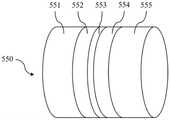
在一些实施例中,第一电极的子电极数量可以包括4个、5个、6个等。在一些实施例中,第一电极的中间的子电极的阻值可以大于其边沿的子电极的阻值。在一些实施例中,多个子电极的阻值可以由中间向两边依次递减。通过这样的子电极设置,可以使得第一电极对第二电极放电(如第一电极的多个子电极对第二电极的多个子电极同时放电)时所形成的电场更均匀。图11是根据本申请一些实施例所示的包括五个子电极的电极结构示意图。在一些实施例中,第一电极可以为电极550。如图11所示,电极550可以包括5个子电极551、552、553、554和555。5个子电极551、552、553、554和555依次首尾拼接组成电极550。在一些实施例中,中间的子电极的材料和/或尺寸可以与边沿的子电极不同,以使得中间的子电极的阻值大于其边沿的子电极的阻值。在一些实施例中,如图11所示,中间的子电极553的尺寸(如电极长度)可以小于边沿的子电极551和555的尺寸,以使得中间的子电极的阻值大于其边沿的子电极的阻值。在一些实施例中,次中间的子电极552和554的尺寸可以介于中间的子电极和边沿的子电极之间,以使得多个子电极的阻值由中间向两边依次递减。In some embodiments, the number of sub-electrodes of the first electrode may include 4, 5, 6, and the like. In some embodiments, the resistance of the middle sub-electrode of the first electrode may be greater than the resistance of the sub-electrodes at the edges thereof. In some embodiments, the resistance values of the plurality of sub-electrodes may decrease sequentially from the middle to the two sides. Such arrangement of the sub-electrodes can make the electric field formed when the first electrode discharges to the second electrode (eg, the plurality of sub-electrodes of the first electrode discharge simultaneously to the plurality of sub-electrodes of the second electrode) more uniform. FIG. 11 is a schematic diagram of an electrode structure including five sub-electrodes according to some embodiments of the present application. In some embodiments, the first electrode may be electrode 550 . As shown in FIG. 11 , the
在一些实施例中,第一电极的多个子电极之间能够形成电压差,从而多个子电极之间能够形成电场,以用于对第一电极附近的病变组织进行消融。在一些实施例中,第一电极的多个子电极中,部分子电极可以与能量发生器的正极连接;部分子电极可以与能量发生器的负极连接,从而使得连接正极的子电极能够相对于连接负极的子电极放电。在一些实施例中,第一电极可以包括三个子电极,中间的子电极可以连接正极,边上的子电极可以连接负极。在一些实施例中,第一电极可以包括4个子电极,4个子电极可以交替连接能量发生器的正极和负极。In some embodiments, a voltage difference can be formed between the plurality of sub-electrodes of the first electrode, so that an electric field can be formed between the plurality of sub-electrodes for ablating the diseased tissue near the first electrode. In some embodiments, among the plurality of sub-electrodes of the first electrode, some sub-electrodes may be connected to the positive electrode of the energy generator; some sub-electrodes may be connected to the negative electrode of the energy generator, so that the sub-electrodes connected to the positive electrode can be connected to the positive electrode The sub-electrode of the negative electrode discharges. In some embodiments, the first electrode may include three sub-electrodes, the middle sub-electrode may be connected to the positive electrode, and the side sub-electrodes may be connected to the negative electrode. In some embodiments, the first electrode may include 4 sub-electrodes, and the 4 sub-electrodes may be alternately connected to the positive and negative electrodes of the energy generator.
图12是根据本申请一些实施例所示的电极间距变化的消融导管的结构示意图。FIG. 12 is a schematic structural diagram of an ablation catheter with varying electrode spacing according to some embodiments of the present application.
在一些实施例中,参见图12,消融导管600可以包括第一支撑杆630。在一些实施例中,消融导管600上可以仅设置一个支撑杆(如第一支撑杆630)。在一些实施例中,第一支撑杆630上可以包括多个(如至少三个)电极631,多个电极631中存在两个相邻电极的间距为第一间距,存在另两个相邻电极的间距为第二间距。第一间距与第二间距不同。在一些实施例中,第一支撑杆630上的每个电极631可以分别通过单独的导线与外部的能量发生器相连,一部分电极可以连接能量发生器的正极,一部分电极可以连接能量发生器的负极。在一些实施例中,多个电极631可以交替连接能量发生器的正极和负极。使用过程中,能量发生器能够控制连接正极的电极向连接负极的电极放电以形成脉冲电场(或电流回路),进而对病变组织进行消融。通过设置不同的第一间距与第二间距,使得在不同的相邻电极之间能够产生不同的脉冲电场,从而能够适用于对不同的病变组织进行消融。在进行消融手术的过程中,医护人员可以根据消融部位病变组织的不同采用不同间距的相邻电极进行消融,通过采用上述结构的消融导管,医护人员只需通过转动消融导管即可实现不同的消融电场场强的选择。In some embodiments, referring to FIG. 12 , the
在一些实施例中,多个电极中任意两个相邻电极的间距均不相同。在一些实施例中,如图12所示,第一支撑杆630上的多个电极631可以沿第一支撑杆630的一端至第一支撑杆630的另一端间隔排列。从第一支撑杆630的一端至另一端,任意两个相邻电极631的间距均不相同。通过将任意两个相邻电极的间距设置为不相同,可以使得第一支撑杆630上能够容纳更多间距不同的相邻电极,以适用于更多病变组织,提升支撑杆的利用率。In some embodiments, the spacing between any two adjacent electrodes in the plurality of electrodes is not the same. In some embodiments, as shown in FIG. 12 , the plurality of
在一些实施例中,从第一支撑杆630的一端至另一端,相邻电极631的间距可以呈规律性变化。在一些实施例中,规律性变化可以包括等差递增、等差递减、等比递增或等比递减等。在一些实施例中,从第一支撑杆630的一端至另一端,相邻电极631的间距可以等差递增。如图12所示,第一支撑杆630上可以设有六个电极631,每两个相邻电极631的间距均不相同。从第一支撑杆630的一端开始向另一端,每两个相邻电极之间产生的五个电极间距均不相同且按比例逐渐增大。在图12所示的实施例中,这五个电极间距之间的比例可以为1:2:3:4:5。通过将相邻电极的间距设置为规律性变化,可以使得消融导管更便于控制。具体而言,规律性变化的电极间距能够使得相邻电极之间所形成的电场也规律性变化,从而更便于医护人员对电场的选择及控制。In some embodiments, from one end of the
图13是根据本申请另一实施例所示的电极间距变化的消融导管的结构示意图。在一些实施例中,如图13所示,消融导管600可以包括第一支撑杆630和第二支撑杆640。在一些实施例中,第一支撑杆630上可以包括多个(如至少三个)电极631,多个电极631中存在两个相邻电极的间距为第一间距,存在另两个相邻电极的间距为第二间距。在一些实施例中,第二支撑杆640上可以包括多个(如至少三个)电极641。在一些实施例中,第二支撑杆640上的多个电极641与第一支撑杆630上的多个电极631一一对应。通过设置两个支撑杆,每个支撑杆上包括间距变化的电极且两个支撑杆上的电极一一对应,能够使得消融导管不仅能够在同一个支撑杆的不同电极之间形成消融电场,还能够在不同支撑杆的电极之间形成消融电场,从而增大消融导管的消融范围,提升消融导管的利用率以及病变组织的消融效率。FIG. 13 is a schematic structural diagram of an ablation catheter with a changing electrode spacing according to another embodiment of the present application. In some embodiments, as shown in FIG. 13 , the
图14是根据本申请一些实施例所示的电极间距可调的消融导管的结构示意图。FIG. 14 is a schematic structural diagram of an ablation catheter with adjustable electrode spacing according to some embodiments of the present application.
在一些实施例中,消融导管600的第一支撑杆630上可以设有电极位置调节机构670。电极位置调节机构670能够用于调节电极631在第一支撑杆630上的位置。在一些实施例中,至少一个电极631的位置能够通过电极位置调节机构670调节,从而使得第一间距与第二间距不同。其中,第一支撑杆630的多个电极631中,某两个相邻电极的间距为第一间距,另两个相邻电极的间距为第二间距。不同的电极间距可以产生不同强度的消融电场,通过设置电极位置调节机构,能够根据实际需要(如不同的病变组织)调节获得不同的电极间距,从而使得消融导管具有更大的适用范围且能够对病变组织实现精准消融。In some embodiments, an electrode
在一些实施例中,如图14所示,消融导管600的第一支撑杆630上设有多个电极631,每个电极631均可以设有对应的电极位置调节机构。通过给每个电极设置对应的电极位置调节机构,能够使得任意两个相邻电极之间的间距均可调整,从而使得电极间距的调节更加灵活,调节结果更加多样。在一些替代性实施例中,多个电极631中,可以每隔一个电极设有对应的电极位置调节机构。In some embodiments, as shown in FIG. 14 , a plurality of
在一些实施例中,电极位置调节机构670可以包括开设在第一支撑杆630上的长条形通孔671。在一些实施例中,由于电极上连接有导线,电极可以被设置为在长条形通孔671的两端之前移动。在一些实施例中,电极位置调节机构670可以进一步包括电极限位结构(图中未示出)。电极限位结构与电极固连,且电极限位结构与长条形通孔671相配合并能够沿长条形通孔671移动。在一些实施例中,电极631可以是套设在第一支撑杆630上的环电极。电极限位结构可以是一条贯穿长条形通孔的限位块,且限位块两端分别与对应的电极内壁固连。限位块能够沿长条形通孔671移动,以带动电极移动,从而实现相邻电极之间间距的调节。在一些实施例中,电极位置可以通过手动调节实现。例如,医务人员可以在手术前手动移动电极或限位块,从而调节电极相对于长条形通孔671的位置。在一些实施例中,电极位置可以通过控制机构调节实现。在一些实施例中,消融设备可以包括用于控制消融导管的控制手柄,电极限位结构可以与绳索连接并能够在绳索的拉动下移动,控制手柄上设有绳索控制机构,绳索控制机构能够拉动绳索从而控制电极限位结构移动,进而实现电极位置的调节。通过设置控制机构调节电极位置,能够实现在消融手术过程中及时对电极位置进行调整,以对病变组织实现精准消融。In some embodiments, the electrode
在一些实施例中,电极位置调节机构670可以包括其他能够实现对电极位置进行调节的机构。在一些实施例中,电极位置调节机构670可以包括开设在第一支撑杆630上的长条形凹槽,电极上可以固设有卡块与凹槽相配合,电极能够相对于第一支撑杆630任意移动,卡块能够保持电极在移动过程中不发生偏转。在一些实施例中,消融导管600中可以不包括电极位置调节机构670。在一些实施例中,电极可以套设在第一支撑杆上,并与第一支撑杆过盈连接,电极能够在外力作用下相对于第一支撑杆移动,从而在没有电极位置调节机构670的情况下实现电极位置的调节。In some embodiments, the electrode
图15是根据本申请另一实施例所示的电极间距可调的消融导管的结构示意图。在一些实施例中,如图15所示,消融导管600可以包括第一支撑杆630和第二支撑杆640。在一些实施例中,第一支撑杆630上设有多个电极631,每个电极631均可以设有对应的电极位置调节机构670。在一些实施例中,第二支撑杆640上可以包括多个电极641,电极641与电极631的数量相等。在一些实施例中,第二支撑杆640上的多个电极641相对于第二支撑杆640固定。在一些实施例中,第二支撑杆640上的多个电极641可以分别设有对应的电极位置调节机构。通过设置两个支撑杆,能够使得消融导管不仅能够在同一个支撑杆的不同电极之间形成消融电场,还能够在不同支撑杆的电极之间形成消融电场,从而增大消融导管的消融范围,提升消融导管的利用率以及病变组织的消融效率。FIG. 15 is a schematic structural diagram of an ablation catheter with adjustable electrode spacing according to another embodiment of the present application. In some embodiments, as shown in FIG. 15 , the
图16是根据本申请一些实施例所示的支撑杆可调的消融导管的第一状态示意图;图17是根据本申请一些实施例所示的支撑杆可调的消融导管的第二状态示意图;图18是根据本申请一些实施例所示的支撑杆可调的消融导管的第三状态示意图;图19是根据本申请另一实施例所示的支撑杆可调的消融导管的结构示意图;图20是根据本申请另一实施例所示的支撑杆可调的消融导管的工作状态示意图;图21是根据本申请又一实施例所示的支撑杆可调的消融导管的结构示意图;图22是根据本申请又一实施例所示的支撑杆可调的消融导管的工作状态示意图。16 is a schematic diagram of a first state of the ablation catheter with adjustable support rods according to some embodiments of the present application; FIG. 17 is a schematic diagram of a second state of the ablation catheter with adjustable support rods according to some embodiments of the present application; Fig. 18 is a schematic diagram of the third state of the ablation catheter with adjustable support rod according to some embodiments of the present application; Fig. 19 is a schematic diagram of the structure of the ablation catheter with adjustable support rod according to another embodiment of the present application; Fig. 20 is a schematic diagram of a working state of an ablation catheter with adjustable support rods according to another embodiment of the present application; FIG. 21 is a schematic structural diagram of an ablation catheter with adjustable support rods according to another embodiment of the present application; FIG. 22 It is a schematic diagram of the working state of the ablation catheter with adjustable support rod according to another embodiment of the present application.
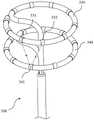
在一些实施例中,如图16-22所示,消融导管700可以包括第一支撑杆730、第二支撑杆740和内管720。消融导管700的第一支撑杆730和第二支撑杆740设置在内管720上,第一支撑杆730和第二支撑杆740上设有多个电极(如第一支撑杆730上的电极731或第二支撑杆740上的电极741)。在一些实施例中,第一支撑杆和第二支撑杆均为环形支撑杆。在一些实施例中,第一支撑杆730和/或第二支撑杆740相对于内管720的角度可调。例如,第一支撑杆730和/或第二支撑杆740所在的平面与内管720的夹角可调。在一些实施例中,内管720可以位于环形的第一支撑杆730和第二支撑杆740的中心连线上,第一支撑杆730和/或第二支持撑杆740可以在角度调节机构(如弯曲度调节绳、电磁体等)的控制下以各自的中心为基准转动(如翻转),以使得第一支撑杆730和/或第二支撑杆740相对于内管720的角度发生变化。在一些实施例中,第一支撑杆730和第二支撑杆740可以朝同一个方向转动。在一些实施例中,第一支撑杆730和第二支撑杆740的其中一者可以保持不动而仅另一者转动。在一些实施例中,第一支撑杆730和第二支撑杆740可以朝不同方向转动。通过设置第一支撑杆730和/或第二支撑杆740相对于内管720的角度可调,能够使得消融导管700适于贴靠不同形状的组织管腔,以更好的对组织管腔中的病变组织进行消融和/或标测。此外,第一支撑杆730和/或第二支撑杆740相对于内管720的角度调整后,第一支撑杆730和第二支撑杆740上对应电极之间的距离相应发生变化,从而能够形成不同的消融电场,以适用于对不同的病变组织进行消融。在一些实施例中,消融导管700可以仅包括一个支撑杆(如第一支撑杆730),该支撑杆相对于内管720的角度可调。In some embodiments, as shown in FIGS. 16-22 , the
在一些实施例中,第一支撑杆730可以通过第一连接杆750与内管720连接,第二支撑杆740可以通过第二连接杆760与内管720连接。第一连接杆750和/或第二连接杆760的弯曲度可调,从而使得第一支撑杆730和/或第二支撑杆740相对于内管720的角度可调。通过将第一支撑杆730和第二支撑杆740分别通过连接杆独立的设置在内管720上,能够便于对第一支撑杆730和第二支撑杆740单独控制,以使消融导管700适用于更多的消融场景。在一些实施例中,消融导管700还包括外管710,外管710套设在内管720外,内管720能够相对于外管710移动,以使得第一支撑杆730和第二支撑杆740能够收缩至外管710中,或者从外管710中伸出以形成环形支撑杆。In some embodiments, the
在一些实施例中,参见图16-18,消融导管700的第一连接杆750和/或第二连接杆760内设有弯曲度调节绳。弯曲度调节绳的一端与第一连接杆和/或第二连接杆连接;弯曲度调节绳能够用于控制第一连接杆750和/或第二连接杆760的弯曲度,从而调节第一支撑杆730和/或第二支撑杆740相对于内管720的角度。如图16-18所示,第一连接杆750内设有弯曲度调节绳781,弯曲度调节绳781的一端可以固定连接在第一连接杆750的一端(如第一连接杆750与第一支撑杆730的连接处),弯曲度调节绳781的另一端可以伸出至消融导管700的外部,与外部的控制机构(如控制手柄)连接。在一些实施例中,第二连接杆760内可以类似的设置弯曲度调节绳782。在一些实施例中,用户可以通过控制机构(如控制手柄)拉动弯曲度调节绳781和/或弯曲度调节绳782,以使得第一连接杆750和/或第二连接杆760弯曲,从而带动第一支撑杆730和/或第二支撑杆740相对于内管720转动。在一些实施例中,用户可以通过控制机构对弯曲度调节绳781和/或弯曲度调节绳782进行放松,以使得第一连接杆750和/或第二连接杆760在自身弹力的作用下恢复自然形状,从而带动第一支撑杆730和/或第二支撑杆740恢复自然状态。In some embodiments, referring to FIGS. 16-18 , the first connecting
在一些实施例中,消融导管700的第一支撑杆730和第二支撑杆740在自然状态下与内管720的角度可以为90度(如图2中消融导管100所处的状态)。在一些实施例中,如图16所示,弯曲度调节绳781和782可以同时被拉动相同的距离,以使得第一连接杆750和第二连接杆760弯曲相同的程度,进而使得第一支撑杆730和第二支撑杆740转动相同的角度。在一些实施例中,在第一支撑杆730和第二支撑杆740转动的过程中,第一支撑杆730形成的平面与第二支撑杆740形成的平面可以保持相互平行。在一些实施例中,如图17所示,弯曲度调节绳781可以不施加拉力,仅弯曲度调节绳782施加拉力,则第一支撑杆730可以保持自然状态,第二支撑杆740在弯曲度调节绳782的拉动下实现转动。在一些实施例中,如图18所示,弯曲度调节绳782可以不被拉动,仅弯曲度调节绳781被拉动,则第二支撑杆740保持自然状态,第一支撑杆730在弯曲度调节绳781的拉动下实现转动。在一些实施例中,若第一支撑杆730或第二支撑杆740在消融/标测的过程中不需要转动,则对应的第一连接杆750或第二连接杆760内可以不设弯曲度调节绳。在一些实施例中,用户可以通过控制机构控制弯曲度调节绳781和/或弯曲度调节绳782的拉动距离,从而控制第一连接杆750和/或第二连接杆760弯曲的程度,进而准确控制第一支撑杆730和/或第二支撑杆740相对于内管720的角度。通过设置弯曲度调节绳能够方便、可靠的调节第一支撑杆730和/或第二支撑杆740相对于内管720的角度。In some embodiments, the
在一些实施例中,第一支撑杆730和/或第二支撑杆740相对于内管720的角度的调节可以通过其他机构实现。在一些实施例中,第一支撑杆730和/或第二支撑杆740相对于内管720的角度的调节可以通过设置电磁体实现。In some embodiments, the adjustment of the angle of the
在一些实施例中,第一支撑杆730上可以设有电磁体(如电磁铁),第二支撑杆740上与第一支撑杆的电磁体对应的位置设有磁性块(如铁块);或者,第一支撑杆730上设有磁性块,第二支撑杆740上与第一支撑杆730的磁性块对应的位置设有电磁体。在一些实施例中,电磁体在通电状态下能够吸引磁性块,从而使得第一支撑杆730和第二支撑杆740均相对于内管720翻转。In some embodiments, an electromagnet (such as an electromagnet) may be provided on the
在一些实施例中,如图19-20所示,第一支撑杆730上可以设有磁性块792,第二支撑杆740上与磁性块792对应的位置可以设有电磁体791。在一些实施例中,磁性块792和电磁体791可以设置在两个相邻电极之间。在一些实施例中,磁性块792和/或电磁体791可以设置在支撑杆内部或支撑杆表面。在一些实施例中,电磁体791可以通过单独的导线与外部控制器连接。控制器能够控制电磁体791通电。在一些实施例中,控制器能够控制电磁体791的电流大小,从而控制电磁体791的磁力大小。在一些实施例中,电磁体791在通电状态下能够吸引磁性块792,从而使得第一支撑杆730和第二支撑杆740上设有磁性块792和电磁体791的位置相互吸引靠近,实现第一支撑杆730和第二支撑杆740相对于内管720翻转。在一些实施例中,控制器能够通过控制电磁体791的电流大小,从而控制电磁体791和磁性块792之间的吸力,进而控制第一支撑杆730和第二支撑杆740相对于内管720翻转的角度。在一些实施例中,电磁体791可以包括固定安装在第二支撑杆740上的铁条791B和缠绕在铁条791B外部的线圈791A,线圈791A可以与外部控制器电连接。在一些实施例中,磁性块792可以固定安装在第二支撑杆740上。磁性块792可以理解为能够被磁体吸引的块,如铁块。当外部的控制器控制线圈791A内有电流通过时,根据电流的磁效应,线圈791A内产生磁场,铁条791B将被线圈791A内的磁场磁化,从而铁条791B将产生磁性,因此具有磁性的铁条791B和磁性块792能够相互吸引。In some embodiments, as shown in FIGS. 19-20 , a
在一些实施例中,图19所示为电磁体791没有通电时的状态,此时第一支撑杆730和第二支撑杆740处于自然状态,第一支撑杆730和第二支撑杆740与内管720的角度可以为90度。在一些实施例中,图20所示为电磁体791通电时的状态,此时第一支撑杆730和第二支撑杆740均相对于内管720翻转。通过在第一支撑杆和第二支撑杆上设置电磁体和磁性块以控制支撑杆翻转,能够使得翻转控制具有简便、可靠、响应速度快等特点。通过第一支撑杆和第二支撑杆均相对于内管翻转,能够使得消融导管700形成特定的形状,以更合适的贴合到特定的组织管腔中。在一些实施例中,第一支撑杆和第二支撑杆均相对于内管翻转后,第一支撑杆和第二支撑杆相互靠拢的一侧的对应电极之间的距离变小,则对应电极之间所形成的电场强度能够增大;而第一支撑杆和第二支撑杆相互远离的一侧的对应电极之间的距离变大,则对应电极之间所形成的电场强度能够减小。因此通过控制第一支撑杆和第二支撑杆均相对于内管翻转,能够获得更多样的脉冲电场,以适用于对不同的病变组织进行消融。在一些实施例中,第一支撑杆730和第二支撑杆740的结构相同,两者相对于内管720翻转的角度的绝对值相等。通过第一支撑杆和第二支撑杆对称翻转(即两者翻转角度的绝对值相等),能够使得消融导管更易于操控(例如,更便于确定每两个对应电极之间的距离)。In some embodiments, FIG. 19 shows the state when the
在一些实施例中,电磁体791和磁性块792可以均设有多个,分别在第二支撑杆740和第一支撑杆730上一一对应设置。在一些实施例中,多个电磁体791设置在第二支撑杆740上,多个磁性块792设置在第一支撑杆730上。在一些实施例中,磁性块792的数量可以与第一支撑杆730上的电极731的数量相等,且电极731与磁性块792间隔分布(即每相邻两个电极731中间设有一个磁性块792)。相应地,电磁体791的数量也可以与第二支撑杆740上的电极741的数量相等,且电极741与电磁体791间隔分布。在一些实施例中,每个电磁体791可以通过单独的导线与外部电源连接。电磁体791在通电状态下能够吸引对应的磁性块792。通过设置多个电磁体791和磁性块792,使得第一支撑杆730和第二支撑杆740能够从多个方向相对于内管720翻转,从而使得消融导管能够适用于更多病变组织的消融。通过精确控制第一支撑杆730和第二支撑杆740的翻转位置,能够使得消融电场的大小区域精确可控,进而确保了消融部位及消融效果的精确可控。In some embodiments, a plurality of
在一些实施例中,第一支撑杆730和/或第二支撑杆740上设有电磁体791,内管720上与第一支撑杆730和/或第二支撑杆740上的电磁体791对应的位置设有磁性块792;或者,第一支撑杆730和/或第二支撑杆740上设有磁性块,内管720上与第一支撑杆730和/或第二支撑杆740上的磁性块对应的位置设有电磁体。电磁体在通电状态下能够吸引磁性块,从而使得第一支撑杆730和/或第二支撑杆740相对于内管720翻转。In some embodiments,
在一些实施例中,参见图21-22,第二支撑杆740上可以设有电磁体791,内管720上与第二支撑杆740上的电磁体791对应的位置设有磁性块792。在一些实施例中,电磁体791可以设置在两个相邻电极之间。在一些实施例中,电磁体791可以通过单独的导线与外部控制器连接。电磁体791在通电状态下能够吸引磁性块792,磁性块792固定在内管720上,从而使得第二支撑杆740上设有电磁体791的端部向内管720上的相对应的磁性块792靠近,实现第二支撑杆740相对于内管720翻转。在一些实施例中,电磁体791可以包括固定安装在第二支撑杆740上的铁条791B和缠绕在铁条791B外部的线圈791A,线圈791A可以与外部控制器电连接。在一些实施例中,控制器能够通过控制电磁体791(如线圈791A)的电流大小,从而控制电磁体791和磁性块792之间的吸力,进而控制第二支撑杆740相对于内管720翻转的角度。在一些实施例中,图21所示为电磁体791没有通电时的状态,此时第一支撑杆730和第二支撑杆740处于自然状态,第一支撑杆730和第二支撑杆740与内管720的角度可以为90度。在一些实施例中,图22所示为电磁体791通电时的状态,此时第二支撑杆740相对于内管720翻转。In some embodiments, referring to FIGS. 21-22 , an
在一些实施例中,电磁体791(或磁性块792)可以设置在第一支撑杆730上,磁性块792(或电磁体791)可以设置在内管720的对应位置上。在一些实施例中,第一支撑杆730和第二支撑杆740上可以均设有电磁体791(或磁性块792),内管720的对应位置上可以均设置磁性块792(或电磁体791)。通过在第一支撑杆730和/或第二支撑杆740上设置电磁体791(或磁性块792),使得第一支撑杆730和第二支撑杆740能够被独立控制相对于内管720翻转,从而使得消融导管700能够适用于更多的消融场景。In some embodiments, the electromagnet 791 (or the magnetic block 792 ) may be disposed on the
在一些实施例中,第一支撑杆730和/或第二支撑杆740上可以设有多个电磁体791,内管720上与第一支撑杆730和/或第二支撑杆740上的多个电磁体791对应的位置设有磁性块792。在一些实施例中,与第一支撑杆730(或第二支撑杆740)上的多个电磁体791对应的位置可以设有一个或多个磁性块792。在一些实施例中,一个磁性块792可以环绕内管720一圈设置,从而使得该磁性块792能够同时适用于对多个电磁体791进行吸引。在一些实施例中,多个磁性块792可以环绕内管720一圈间隔设置,每个磁性块792可以设置在与每个电磁体791对应的位置。通过设置多个电磁体791与对应的磁性块792,使得第一支撑杆730和第二支撑杆740能够从多个方向相对于内管720翻转,从而使得消融导管700能够适用于更多病变组织的消融。通过精确控制第一支撑杆730和第二支撑杆740的翻转位置,能够使得消融电场的大小区域精确可控,进而确保了消融部位及消融效果的精确可控。In some embodiments, the
本申请一些实施例还涉及一种消融设备,该消融设备可以包括本申请任一实施例所涉及的消融导管。在一些实施例中,消融设备可以进一步包括控制手柄,控制手柄可以用于对消融导管进行控制。例如,控制手柄可以控制消融导管输送进入人体以及控制消融导管从人体内退出。又例如,控制手柄可以用于控制消融导管的内管沿长度方向相对于外管移动。再例如,控制手柄上可以设有绳索控制机构,绳索控制机构能够拉动绳索从而控制电极限位结构移动。又例如,控制手柄可以用于控制弯曲度调节绳,以使得连接杆(如第一连接杆和/或第二连接杆)弯曲。在一些实施例中,消融设备可以进一步包括能量发生器,能量发生器可以用于控制电极之间放电以形成脉冲电场。在一些实施例中,消融设备可以进一步包括标测装置,标测装置能够用于获取电极之间标测到的电位信号。在一些实施例中,标测装置与能量发生器可以为同一装置也可以为不同的装置。Some embodiments of the present application also relate to an ablation device, and the ablation device may include the ablation catheter involved in any of the embodiments of the present application. In some embodiments, the ablation device may further include a control handle, which may be used to control the ablation catheter. For example, the control handle can control the delivery of the ablation catheter into the body and the withdrawal of the ablation catheter from the body. As another example, a control handle may be used to control movement of the inner tube of the ablation catheter relative to the outer tube in the lengthwise direction. For another example, a rope control mechanism may be provided on the control handle, and the rope control mechanism can pull the rope to control the movement of the electric limit position structure. As another example, the control handle may be used to control the flexion adjustment cord to bend the connecting rod (eg, the first connecting rod and/or the second connecting rod). In some embodiments, the ablation device may further comprise an energy generator, which may be used to control the discharge between the electrodes to form a pulsed electric field. In some embodiments, the ablation apparatus may further comprise a mapping device, which can be used to obtain the potential signals mapped between the electrodes. In some embodiments, the mapping device and the energy generator may be the same device or different devices.
应当注意的是,上述有关消融导管和设备的描述仅仅是为了示例和说明,而不限定本申请的适用范围。对于本领域技术人员来说,在本申请的指导下可以对消融导管和设备进行各种修正和改变;然而,这些修正和改变仍在本申请的范围之内。例如,一些实施例中的第一支撑杆和第二支撑杆可以互换,如第二支撑杆可以更靠近消融导管的前端。又例如,在图3-5所示的消融导管200的基础上,可以实现多个电极对多个电极放电、电极之间间距变化、支撑杆相对于内管翻转等功能。再例如,在一个消融导管上可以同时具有材料、尺寸和构造不同的电极。又例如,在一个消融导管上可以同时具有电极间距可调以及支撑杆可相对于内管翻转的功能。还例如,本说明书所描述的各个实施例中的技术特征能够进行任意合理的拆分、组合,以形成新的消融导管或设备。诸如此类的变形,均在本申请的保护范围之内。It should be noted that the above description of the ablation catheter and device is for example and illustration only, and does not limit the scope of application of the present application. Various modifications and changes to ablation catheters and devices can be made to ablation catheters and devices under the guidance of this application to those skilled in the art; however, such modifications and changes are still within the scope of this application. For example, the first support rod and the second support rod may be interchanged in some embodiments, eg, the second support rod may be closer to the front end of the ablation catheter. For another example, on the basis of the
本申请一些实施例所披露的消融导管和设备可能带来的有益效果包括但不限于:(1)能够实现高密度电场消融,同时又能及时确认脉冲场消融导管的消融效果;(2)消融导管能够牢固地贴靠组织管腔,能够适应组织管腔的不同形状,以对病变组织进行可靠的消融;(3)能够实现高密度标测、原位标测,有效提升标测准确性和及时性;(4)能够形成不同范围、形状、强度的消融电场,能够针对性地对不同的病变组织进行消融、标测;(5)消融电场精确可控,进而使得消融部位及消融效果精确可控;(6)操控简便,适于应用。需要说明的是,不同实施例可能产生的有益效果不同,在不同的实施例里,可能产生的有益效果可以是以上任意一种或几种的组合,也可以是其他任何可能获得的有益效果。The possible beneficial effects of the ablation catheter and device disclosed in some embodiments of the present application include, but are not limited to: (1) high-density electric field ablation can be achieved, and at the same time, the ablation effect of the pulsed field ablation catheter can be confirmed in time; (2) ablation The catheter can be firmly attached to the tissue lumen, and can adapt to the different shapes of the tissue lumen, so as to reliably ablate the diseased tissue; (3) It can realize high-density mapping and in-situ mapping, effectively improving the accuracy of mapping and Timeliness; (4) It can form ablation electric fields of different ranges, shapes and intensities, and can ablate and map different diseased tissues in a targeted manner; (5) The ablation electric field is precisely controllable, thereby making the ablation site and ablation effect accurate Controllable; (6) Easy to operate and suitable for application. It should be noted that different embodiments may have different beneficial effects, and in different embodiments, the possible beneficial effects may be any one or a combination of the above, or any other possible beneficial effects.
以上仅为本申请的较佳实施例而已,并不用以限制本申请,凡在本申请的精神和原则之内所作的任何修改、等同替换和改进等,均应包含在本申请的保护范围之内。本申请使用了特定词语来描述本申请的实施例。如“一个实施例”、“一实施例”、和/或“一些实施例”意指与本申请至少一个实施例相关的某一特征、结构或特点。因此,应强调并注意的是,本说明书中在不同位置两次或多次提及的“一些实施例”或“一个实施例”或“一些替代性实施例”并不一定是指同一实施例。此外,本申请的一个或多个实施例中的某些特征、结构或特点可以进行适当的组合。The above are only preferred embodiments of the present application and are not intended to limit the present application. Any modifications, equivalent replacements and improvements made within the spirit and principles of the present application shall be included in the protection scope of the present application. Inside. This application uses specific terms to describe the embodiments of the application. Such as "one embodiment," "an embodiment," and/or "some embodiments" means a certain feature, structure, or characteristic associated with at least one embodiment of the present application. Therefore, it should be emphasized and noted that two or more references to "some embodiments" or "one embodiment" or "some alternative embodiments" in various places in this specification are not necessarily referring to the same embodiment . Furthermore, certain features, structures or characteristics of the one or more embodiments of the present application may be combined as appropriate.
同理,应当注意的是,为了简化本申请披露的表述,从而帮助对一个或多个申请实施例的理解,前文对本申请实施例的描述中,有时会将多种特征归并至一个实施例、附图或对其的描述中。但是,这种披露方法并不意味着本申请对象所需要的特征比权利要求中提及的特征多。实际上,实施例的特征要少于上述披露的单个实施例的全部特征。Similarly, it should be noted that, in order to simplify the expressions disclosed in the present application and thus help the understanding of one or more embodiments of the present application, in the foregoing description of the embodiments of the present application, various features are sometimes combined into one embodiment, in the drawings or descriptions thereof. However, this method of disclosure does not imply that the subject matter of the application requires more features than those mentioned in the claims. Indeed, there are fewer features of an embodiment than all of the features of a single embodiment disclosed above.
Claims (10)
Translated fromChinesePriority Applications (1)
| Application Number | Priority Date | Filing Date | Title |
|---|---|---|---|
| CN202210415257.8ACN114767256A (en) | 2022-01-27 | 2022-01-27 | Ablation catheter and device with variable electrode spacing |
Applications Claiming Priority (2)
| Application Number | Priority Date | Filing Date | Title |
|---|---|---|---|
| CN202210415257.8ACN114767256A (en) | 2022-01-27 | 2022-01-27 | Ablation catheter and device with variable electrode spacing |
| CN202210098625.0ACN114366284A (en) | 2022-01-27 | 2022-01-27 | An ablation catheter and device |
Related Parent Applications (1)
| Application Number | Title | Priority Date | Filing Date |
|---|---|---|---|
| CN202210098625.0ADivisionCN114366284A (en) | 2022-01-27 | 2022-01-27 | An ablation catheter and device |
Publications (1)
| Publication Number | Publication Date |
|---|---|
| CN114767256Atrue CN114767256A (en) | 2022-07-22 |
Family
ID=81145855
Family Applications (3)
| Application Number | Title | Priority Date | Filing Date |
|---|---|---|---|
| CN202210415257.8APendingCN114767256A (en) | 2022-01-27 | 2022-01-27 | Ablation catheter and device with variable electrode spacing |
| CN202210098625.0APendingCN114366284A (en) | 2022-01-27 | 2022-01-27 | An ablation catheter and device |
| CN202210416189.7APendingCN115024812A (en) | 2022-01-27 | 2022-01-27 | Ablation catheter with adjustable supporting rod and equipment |
Family Applications After (2)
| Application Number | Title | Priority Date | Filing Date |
|---|---|---|---|
| CN202210098625.0APendingCN114366284A (en) | 2022-01-27 | 2022-01-27 | An ablation catheter and device |
| CN202210416189.7APendingCN115024812A (en) | 2022-01-27 | 2022-01-27 | Ablation catheter with adjustable supporting rod and equipment |
Country Status (1)
| Country | Link |
|---|---|
| CN (3) | CN114767256A (en) |
Families Citing this family (1)
| Publication number | Priority date | Publication date | Assignee | Title |
|---|---|---|---|---|
| CN117838283A (en)* | 2024-01-23 | 2024-04-09 | 牛国栋 | Nanosecond pulse ablation system |
Citations (4)
| Publication number | Priority date | Publication date | Assignee | Title |
|---|---|---|---|---|
| US20020177765A1 (en)* | 2001-05-24 | 2002-11-28 | Bowe Wade A. | Ablation and high-resolution mapping catheter system for pulmonary vein foci elimination |
| US20070005053A1 (en)* | 2005-06-30 | 2007-01-04 | Dando Jeremy D | Ablation catheter with contoured openings in insulated electrodes |
| CN112055569A (en)* | 2018-01-24 | 2020-12-08 | 美敦力阿迪安卢森堡有限公司 | multi-electrode catheter |
| CN113081239A (en)* | 2021-03-31 | 2021-07-09 | 上海睿刀医疗科技有限公司 | Cage-shaped electrode catheter and ablation device comprising same |
Family Cites Families (15)
| Publication number | Priority date | Publication date | Assignee | Title |
|---|---|---|---|---|
| US6287306B1 (en)* | 1998-06-22 | 2001-09-11 | Daig Corporation | Even temperature linear lesion ablation catheter |
| AUPS226402A0 (en)* | 2002-05-13 | 2002-06-13 | Advanced Metal Coatings Pty Limited | An ablation catheter |
| US7806893B2 (en)* | 2005-04-26 | 2010-10-05 | Boston Scientific Scimed, Inc. | Apparatus and method for making a spherical lesion |
| EP3360497B1 (en)* | 2015-02-03 | 2024-05-22 | Shanghai Golden Leaf Med Tec Co., Ltd. | Radio-frequency ablation catheter having spiral structure and device thereof |
| CN107405099B (en)* | 2015-05-11 | 2021-02-09 | 圣犹达医疗用品心脏病学部门有限公司 | High density mapping and ablation catheter |
| AU2016275556A1 (en)* | 2015-06-10 | 2017-12-14 | Cathrx Ltd | Double shape catheter |
| WO2017024306A1 (en)* | 2015-08-06 | 2017-02-09 | Apama Medical, Inc. | Multipurpose electrode |
| US11364072B2 (en)* | 2017-01-27 | 2022-06-21 | Medtronic, Inc. | Catheter electrodes for energy management |
| EP3629964B1 (en)* | 2017-05-23 | 2024-09-25 | Boston Scientific Scimed Inc. | Lesion maturation prediction using local impedance |
| CN110179537B (en)* | 2019-04-28 | 2020-12-08 | 华中科技大学 | A multi-claw active conformal ablation needle with magnetic control |
| CN213525440U (en)* | 2020-06-29 | 2021-06-25 | 杭州诺茂医疗科技有限公司 | Ablation catheter |
| CN212415889U (en)* | 2020-08-17 | 2021-01-29 | 上海微创电生理医疗科技股份有限公司 | medical catheter |
| CN112914715B (en)* | 2020-12-14 | 2025-01-24 | 绍兴梅奥心磁医疗科技有限公司 | A ring electrode pulse electric field ablation device |
| CN215384585U (en)* | 2021-01-12 | 2022-01-04 | 深圳北芯生命科技股份有限公司 | Ablation catheter and medical device comprising same |
| CN113081240B (en)* | 2021-03-31 | 2022-03-01 | 上海睿刀医疗科技有限公司 | Cage-shaped electrode catheter and ablation device comprising same |
- 2022
- 2022-01-27CNCN202210415257.8Apatent/CN114767256A/enactivePending
- 2022-01-27CNCN202210098625.0Apatent/CN114366284A/enactivePending
- 2022-01-27CNCN202210416189.7Apatent/CN115024812A/enactivePending
Patent Citations (4)
| Publication number | Priority date | Publication date | Assignee | Title |
|---|---|---|---|---|
| US20020177765A1 (en)* | 2001-05-24 | 2002-11-28 | Bowe Wade A. | Ablation and high-resolution mapping catheter system for pulmonary vein foci elimination |
| US20070005053A1 (en)* | 2005-06-30 | 2007-01-04 | Dando Jeremy D | Ablation catheter with contoured openings in insulated electrodes |
| CN112055569A (en)* | 2018-01-24 | 2020-12-08 | 美敦力阿迪安卢森堡有限公司 | multi-electrode catheter |
| CN113081239A (en)* | 2021-03-31 | 2021-07-09 | 上海睿刀医疗科技有限公司 | Cage-shaped electrode catheter and ablation device comprising same |
Also Published As
| Publication number | Publication date |
|---|---|
| CN114366284A (en) | 2022-04-19 |
| CN115024812A (en) | 2022-09-09 |
Similar Documents
| Publication | Publication Date | Title |
|---|---|---|
| US20220313355A1 (en) | Catheter electrodes for energy management | |
| US20220257938A1 (en) | Expandable elements for delivery of electric fields | |
| US7094235B2 (en) | Method and apparatus for tissue ablation | |
| WO2022007490A1 (en) | System for treating arrhythmias using pulsed electric field ablation technology | |
| US7115124B1 (en) | Device and method for tissue ablation using bipolar radio-frequency current | |
| JP2025124839A (en) | Ablation device for treating a target region of tissue within an organ - Patent Application 20070122997 | |
| US20100049191A1 (en) | Tissue ablator | |
| US20130338467A1 (en) | Electrode catheter device with indifferent electrode for direct current tissue therapies | |
| CN114404035B (en) | Ablation Device | |
| US20100217074A1 (en) | Variable Size Apparatus for Supporting Diagnostic and/or Therapeutic Elements in Contact With Tissue | |
| CN115363745B (en) | Ablation Catheter | |
| CN114376723B (en) | Irreversible electroporation ablation needle, needle channel ablation device and ablation device | |
| JP2023528084A (en) | Ablation device for treating target areas of tissue within an organ | |
| CN106821494B (en) | Plasma operation electrode | |
| CN114767256A (en) | Ablation catheter and device with variable electrode spacing | |
| US20090125011A1 (en) | Devices, Methods and Kits for Substantial and Uniform Ablation about a Linear Bipolar Array of Electrodes | |
| CN217162276U (en) | Ablation catheter and device | |
| CN119564327B (en) | A catheter capable of performing local ablation | |
| US20240415570A1 (en) | Devices, systems, and methods for preventing arcing between electrodes for medical procedures | |
| CN117426863A (en) | Tissue ablation using high frequency monopole IRE | |
| CN103220994B (en) | Lead Sets with Extraneous Electrodes for Direct Current Tissue Therapy | |
| CN115956993A (en) | an ablation catheter |
Legal Events
| Date | Code | Title | Description |
|---|---|---|---|
| PB01 | Publication | ||
| PB01 | Publication | ||
| SE01 | Entry into force of request for substantive examination | ||
| SE01 | Entry into force of request for substantive examination |