CN114764779A - Computing device and defect detection method for near-eye display device - Google Patents
Computing device and defect detection method for near-eye display deviceDownload PDFInfo
- Publication number
- CN114764779A CN114764779ACN202110074515.6ACN202110074515ACN114764779ACN 114764779 ACN114764779 ACN 114764779ACN 202110074515 ACN202110074515 ACN 202110074515ACN 114764779 ACN114764779 ACN 114764779A
- Authority
- CN
- China
- Prior art keywords
- image
- interest
- eye display
- display device
- pixel
- Prior art date
- Legal status (The legal status is an assumption and is not a legal conclusion. Google has not performed a legal analysis and makes no representation as to the accuracy of the status listed.)
- Granted
Links
Images


Classifications
- G—PHYSICS
- G06—COMPUTING OR CALCULATING; COUNTING
- G06T—IMAGE DATA PROCESSING OR GENERATION, IN GENERAL
- G06T5/00—Image enhancement or restoration
- G06T5/77—Retouching; Inpainting; Scratch removal
- G—PHYSICS
- G06—COMPUTING OR CALCULATING; COUNTING
- G06T—IMAGE DATA PROCESSING OR GENERATION, IN GENERAL
- G06T7/00—Image analysis
- G06T7/0002—Inspection of images, e.g. flaw detection
- G06T7/0004—Industrial image inspection
- G06T7/001—Industrial image inspection using an image reference approach
- G—PHYSICS
- G06—COMPUTING OR CALCULATING; COUNTING
- G06T—IMAGE DATA PROCESSING OR GENERATION, IN GENERAL
- G06T5/00—Image enhancement or restoration
- G06T5/10—Image enhancement or restoration using non-spatial domain filtering
- G—PHYSICS
- G06—COMPUTING OR CALCULATING; COUNTING
- G06T—IMAGE DATA PROCESSING OR GENERATION, IN GENERAL
- G06T5/00—Image enhancement or restoration
- G06T5/70—Denoising; Smoothing
- G—PHYSICS
- G06—COMPUTING OR CALCULATING; COUNTING
- G06T—IMAGE DATA PROCESSING OR GENERATION, IN GENERAL
- G06T5/00—Image enhancement or restoration
- G06T5/90—Dynamic range modification of images or parts thereof
- G06T5/92—Dynamic range modification of images or parts thereof based on global image properties
- G—PHYSICS
- G06—COMPUTING OR CALCULATING; COUNTING
- G06T—IMAGE DATA PROCESSING OR GENERATION, IN GENERAL
- G06T7/00—Image analysis
- G06T7/10—Segmentation; Edge detection
- G06T7/11—Region-based segmentation
- G—PHYSICS
- G06—COMPUTING OR CALCULATING; COUNTING
- G06T—IMAGE DATA PROCESSING OR GENERATION, IN GENERAL
- G06T7/00—Image analysis
- G06T7/10—Segmentation; Edge detection
- G06T7/136—Segmentation; Edge detection involving thresholding
- G—PHYSICS
- G06—COMPUTING OR CALCULATING; COUNTING
- G06T—IMAGE DATA PROCESSING OR GENERATION, IN GENERAL
- G06T7/00—Image analysis
- G06T7/40—Analysis of texture
- G06T7/41—Analysis of texture based on statistical description of texture
- G06T7/44—Analysis of texture based on statistical description of texture using image operators, e.g. filters, edge density metrics or local histograms
- G—PHYSICS
- G06—COMPUTING OR CALCULATING; COUNTING
- G06T—IMAGE DATA PROCESSING OR GENERATION, IN GENERAL
- G06T7/00—Image analysis
- G06T7/70—Determining position or orientation of objects or cameras
- H—ELECTRICITY
- H04—ELECTRIC COMMUNICATION TECHNIQUE
- H04N—PICTORIAL COMMUNICATION, e.g. TELEVISION
- H04N23/00—Cameras or camera modules comprising electronic image sensors; Control thereof
- H04N23/70—Circuitry for compensating brightness variation in the scene
- H04N23/73—Circuitry for compensating brightness variation in the scene by influencing the exposure time
- G—PHYSICS
- G06—COMPUTING OR CALCULATING; COUNTING
- G06T—IMAGE DATA PROCESSING OR GENERATION, IN GENERAL
- G06T2207/00—Indexing scheme for image analysis or image enhancement
- G06T2207/10—Image acquisition modality
- G06T2207/10004—Still image; Photographic image
- G—PHYSICS
- G06—COMPUTING OR CALCULATING; COUNTING
- G06T—IMAGE DATA PROCESSING OR GENERATION, IN GENERAL
- G06T2207/00—Indexing scheme for image analysis or image enhancement
- G06T2207/20—Special algorithmic details
- G06T2207/20021—Dividing image into blocks, subimages or windows
- G—PHYSICS
- G06—COMPUTING OR CALCULATING; COUNTING
- G06T—IMAGE DATA PROCESSING OR GENERATION, IN GENERAL
- G06T2207/00—Indexing scheme for image analysis or image enhancement
- G06T2207/20—Special algorithmic details
- G06T2207/20048—Transform domain processing
- G06T2207/20056—Discrete and fast Fourier transform, [DFT, FFT]
- G—PHYSICS
- G06—COMPUTING OR CALCULATING; COUNTING
- G06T—IMAGE DATA PROCESSING OR GENERATION, IN GENERAL
- G06T2207/00—Indexing scheme for image analysis or image enhancement
- G06T2207/20—Special algorithmic details
- G06T2207/20172—Image enhancement details
- G06T2207/20208—High dynamic range [HDR] image processing
- G—PHYSICS
- G06—COMPUTING OR CALCULATING; COUNTING
- G06T—IMAGE DATA PROCESSING OR GENERATION, IN GENERAL
- G06T2207/00—Indexing scheme for image analysis or image enhancement
- G06T2207/20—Special algorithmic details
- G06T2207/20212—Image combination
- G06T2207/20224—Image subtraction
- G—PHYSICS
- G06—COMPUTING OR CALCULATING; COUNTING
- G06T—IMAGE DATA PROCESSING OR GENERATION, IN GENERAL
- G06T2207/00—Indexing scheme for image analysis or image enhancement
- G06T2207/30—Subject of image; Context of image processing
- G06T2207/30108—Industrial image inspection
- G06T2207/30121—CRT, LCD or plasma display
Landscapes
- Engineering & Computer Science (AREA)
- Physics & Mathematics (AREA)
- General Physics & Mathematics (AREA)
- Theoretical Computer Science (AREA)
- Computer Vision & Pattern Recognition (AREA)
- Quality & Reliability (AREA)
- Multimedia (AREA)
- Signal Processing (AREA)
- Probability & Statistics with Applications (AREA)
- Image Analysis (AREA)
- Eye Examination Apparatus (AREA)
Abstract
Description
Translated fromChinese技术领域technical field
本发明是有关于图像,特别是有关于一种运算装置及用于近眼显示装置(near-eye display,NED)的缺陷检测方法。The present invention relates to images, and more particularly, to a computing device and a defect detection method for a near-eye display (NED).
背景技术Background technique
随着科技进步,近眼显示装置(例如虚拟实境装置及增强现实装置)也愈来愈普及。然而,现今的近眼显示装置往往会使用视野范围大于90度的光学模组(例如菲涅耳透镜),且会造成外围区域的成像品质较差。对于近眼显示装置的制造厂商而言,需要在近眼显示装置组装完成后才能进行缺陷(包含污点及亮点)检测。基于上述光学特性,采用传统的计算机视觉技术或人工目检方式并无法准确地判断出近眼显示装置的显示面板及光学模组上的污点及亮点。With the advancement of technology, near-eye display devices, such as virtual reality devices and augmented reality devices, are becoming more and more popular. However, today's near-eye display devices often use optical modules with a field of view greater than 90 degrees (eg, a Fresnel lens), which results in poor imaging quality in peripheral areas. For manufacturers of near-eye display devices, defects (including stains and bright spots) can only be detected after the near-eye display devices are assembled. Based on the above optical characteristics, the traditional computer vision technology or manual visual inspection method cannot accurately determine the stains and bright spots on the display panel and the optical module of the near-eye display device.
因此,需要一种运算装置及用于近眼显示装置的缺陷检测方法以解决上述问题。Therefore, a computing device and a defect detection method for a near-eye display device are needed to solve the above problems.
发明内容SUMMARY OF THE INVENTION
本发明是提供一种用于近眼显示装置的缺陷检测方法,该近眼显示装置包括显示面板及菲涅耳透镜,该方法包括:依据相机对该显示面板分别播放测试图案图像及测试背景图像时经过该菲涅耳透镜进行拍摄的第一图像及第二图像以得到参考图像及待测图像;对该参考图像及该待测图像分别执行快速傅立叶转换以得到频域参考图像及频域待测图像;对该频域参考图像及该频域待测图像分别应用带通滤波器以得到第一滤波图像及第二滤波图像;将该第一滤波图像及该第二滤波图像分别分割为多个第一感兴趣区域及多个第二感兴趣区域,其中所述多个第一感兴趣区域对应所述多个第二感兴趣区域;统计各个第一感兴趣区域中的像素值以得到相应于各个第一感兴趣区域的直方图,并且计算在各个第一感兴趣区域的直方图中在预定截止比例以上的像素值的平均值以作为各个第一感兴趣区域相应的阈值;依据在该第一滤波图像的各个第一感兴趣区域相应的该阈值以建立阈值图,并将在该第二滤波图像的各个第二感兴趣区域中的各像素与该阈值图中相应的该阈值进行比较以产生在该第二滤波图像的各像素相应的判断结果;以及依据在该第二滤波图像的各像素相应的该判断结果以建立该近眼显示装置的缺陷状态图。The present invention provides a defect detection method for a near-eye display device. The near-eye display device includes a display panel and a Fresnel lens. The method includes: according to a camera, when a test pattern image and a test background image are respectively played on the display panel, the The first image and the second image captured by the Fresnel lens are used to obtain the reference image and the image to be tested; the reference image and the image to be tested are respectively subjected to fast Fourier transform to obtain the reference image in the frequency domain and the image to be tested in the frequency domain ; Apply a bandpass filter to the frequency domain reference image and the frequency domain image to be tested respectively to obtain the first filtered image and the second filtered image; Divide the first filtered image and the second filtered image into a plurality of first filtered images respectively A region of interest and a plurality of second regions of interest, wherein the plurality of first regions of interest correspond to the plurality of second regions of interest; and the pixel values in each of the first regions of interest are counted to obtain corresponding The histogram of the first region of interest, and the average value of the pixel values above the predetermined cut-off ratio in the histogram of each first region of interest is calculated as the corresponding threshold value of each first region of interest; filtering the threshold corresponding to each first region of interest of the image to create a threshold map, and comparing each pixel in each second region of interest of the second filtered image with the threshold corresponding to the threshold map to generate The judgment result corresponding to each pixel of the second filtered image; and a defect state diagram of the near-eye display device is established according to the judgment result corresponding to each pixel of the second filtered image.
在一些实施例中,该缺陷检测方法执行污点检测,且该第一图像及该第二图像分别为该参考图像及该待测图像。该测试背景图像为全白图像,且该测试图案图像为该测试背景图像覆盖多个测试点。In some embodiments, the defect detection method performs stain detection, and the first image and the second image are the reference image and the image to be tested, respectively. The test background image is an all-white image, and the test pattern image is that the test background image covers a plurality of test points.
在一些实施例中,该第一图像及该第二图像是分别由多张第一曝光图像及多张第二曝光图像经由图像融合所得到的高动态范围图像,且所述多个第一曝光图像及所述多个第二曝光图像是在该近眼显示装置分别播放该测试图案图像及该测试背景图像时由该相机使用不同曝光值拍摄而得。In some embodiments, the first image and the second image are high dynamic range images obtained from a plurality of first exposure images and a plurality of second exposure images respectively through image fusion, and the plurality of first exposure images The image and the plurality of second exposure images are captured by the camera using different exposure values when the near-eye display device respectively plays the test pattern image and the test background image.
在另一些实施例中,该缺陷检测方法执行亮点检测,且该测试背景图像包括中心区域及外围区域,且该中心区域及该外围区域分别具有第一灰阶值及第二灰阶值,且该第二灰阶值大于该第一灰阶值,且该测试图案图像为该测试背景图像覆盖多个测试点。该中心区域为该测试背景图像的0至0.5的视野范围的区域,且该外围区域为该测试背景图像的0.5至1的视野范围的区域。In other embodiments, the defect detection method performs bright spot detection, and the test background image includes a central area and a peripheral area, and the central area and the peripheral area have a first grayscale value and a second grayscale value, respectively, and The second grayscale value is greater than the first grayscale value, and the test pattern image covers a plurality of test points for the test background image. The central area is the area of the field of view of 0 to 0.5 of the test background image, and the peripheral area is the area of the field of view of 0.5 to 1 of the test background image.
在一些实施例中,该第一图像及该第二图像是分别由多张第一曝光图像及多张第二曝光图像经由图像融合所得到的高动态范围图像,且所述多个第一曝光图像及所述多个第二曝光图像是在该近眼显示装置分别播放该测试图案图像及该测试背景图像时由该相机使用不同曝光值拍摄而得。In some embodiments, the first image and the second image are high dynamic range images obtained from a plurality of first exposure images and a plurality of second exposure images respectively through image fusion, and the plurality of first exposure images The image and the plurality of second exposure images are captured by the camera using different exposure values when the near-eye display device respectively plays the test pattern image and the test background image.
在一些实施例中,依据该相机对该近眼显示装置分别播放测试图案图像及测试背景图像时进行拍摄的第一图像及第二图像以得到参考图像及待测图像的步骤包括:对该第一图像及该第二图像进行图像模糊化处理以得到模糊化第一图像及模糊化第二图像;将该第一图像及该第二图像分别减去该模糊化第一图像及该模糊化第二图像以得到第一差值图像及第二差值图像;将该第一差值图像及该第二差值图像中的小于0的像素值进行像素修剪处理以分别得到第一修剪差值图像及第二修剪差值图像;以及将该第一修剪差值图像及该第二修剪差值图像设定为该参考图像及该待测图像。In some embodiments, the step of obtaining a reference image and a to-be-measured image according to the first image and the second image captured when the camera plays the test pattern image and the test background image respectively to the near-eye display device includes: The image and the second image are subjected to image blurring processing to obtain a blurred first image and a blurred second image; the first image and the second image are respectively subtracted from the blurred first image and the blurred second image. image to obtain a first difference image and a second difference image; perform pixel trimming processing on pixel values less than 0 in the first difference image and the second difference image to obtain the first trimmed difference image and the second difference image respectively. a second trimmed difference image; and setting the first trimmed difference image and the second trimmed difference image as the reference image and the image to be tested.
在一些实施例中,各个第一感兴趣区域相应的该阈值随着各个第一感兴趣区域距离该第一滤波图像的中心点的距离而变小。In some embodiments, the threshold corresponding to each first region of interest decreases as each first region of interest is distanced from a center point of the first filtered image.
本发明更提供一种运算装置,用于检测近眼显示装置的缺陷,该近眼显示装置包括显示面板及菲涅耳透镜,该运算装置包括:非暂时性存储器,用以储存缺陷检测程序;以及处理器,用以执行该缺陷检测程序以执行下列步骤:依据相机对该显示面板分别播放测试图案图像及测试背景图像时经过该菲涅耳透镜进行拍摄的第一图像及第二图像以得到参考图像及待测图像;对该参考图像及该待测图像分别执行快速傅立叶转换以得到频域参考图像及频域待测图像;对该频域参考图像及该频域待测图像分别应用带通滤波器以得到第一滤波图像及第二滤波图像;将该第一滤波图像及该第二滤波图像分别分割为多个第一感兴趣区域及多个第二感兴趣区域,其中所述多个第一感兴趣区域对应所述多个第二感兴趣区域;统计各个第一感兴趣区域中的像素值以得到相应于各个第一感兴趣区域的直方图,并且计算在各个第一感兴趣区域的直方图中在预定截止比例以上的像素值的平均值以作为各个第一感兴趣区域相应的阈值;依据在该第一滤波图像的各个第一感兴趣区域相应的该阈值以建立阈值图,并将在该第二滤波图像的各个第二感兴趣区域中的各像素与该阈值图中相应的该阈值进行比较以产生在该第二滤波图像的各像素相应的判断结果;以及依据在该第二滤波图像的各像素相应的该判断结果以建立该近眼显示装置的缺陷状态图。The present invention further provides a computing device for detecting defects of a near-eye display device, the near-eye display device includes a display panel and a Fresnel lens, the computing device includes: a non-transitory memory for storing a defect detection program; and a processing a device for executing the defect detection program to perform the following steps: obtaining a reference image according to the first image and the second image captured by the Fresnel lens when the camera plays the test pattern image and the test background image respectively to the display panel and the image to be tested; respectively perform fast Fourier transform on the reference image and the image to be tested to obtain the reference image in the frequency domain and the image to be tested in the frequency domain; apply bandpass filtering to the reference image in the frequency domain and the image to be tested in the frequency domain respectively to obtain a first filtered image and a second filtered image; the first filtered image and the second filtered image are respectively divided into a plurality of first regions of interest and a plurality of second regions of interest, wherein the plurality of first regions of interest A region of interest corresponds to the plurality of second regions of interest; the pixel values in each of the first regions of interest are counted to obtain a histogram corresponding to each of the first regions of interest, and the The average value of the pixel values above a predetermined cut-off ratio in the histogram is used as the corresponding threshold value of each first region of interest; a threshold value map is established according to the corresponding threshold value of each first region of interest in the first filtered image, and comparing each pixel in each second region of interest in the second filtered image with the corresponding threshold in the threshold map to generate a judgment result corresponding to each pixel in the second filtered image; and The judgment results corresponding to each pixel of the two filtered images are used to establish a defect state diagram of the near-eye display device.
附图说明Description of drawings
图1A为依据本发明实施例中的缺陷检测系统的方块图。FIG. 1A is a block diagram of a defect detection system according to an embodiment of the present invention.
图1B为依据本发明图1A的实施例中的利用相机拍摄近眼显示装置的图像的示意图。FIG. 1B is a schematic diagram of using a camera to capture an image of the near-eye display device in the embodiment of FIG. 1A according to the present invention.
图2A为依据本发明实施例中的测试图案图像的示意图。FIG. 2A is a schematic diagram of a test pattern image according to an embodiment of the present invention.
图2B为依据本发明图2A实施例中的第一滤波图像的示意图。FIG. 2B is a schematic diagram of the first filtered image in the embodiment of FIG. 2A according to the present invention.
图2C为依据本发明图2A实施例中第一滤波图像的中心感兴趣区域的像素值的直方图。FIG. 2C is a histogram of pixel values of the central region of interest of the first filtered image according to the embodiment of FIG. 2A of the present invention.
图3为依据本发明实施例中用于亮点检测的测试图案图像的示意图。FIG. 3 is a schematic diagram of a test pattern image for bright spot detection according to an embodiment of the present invention.
图4A为依据本发明实施例中的用于近眼显示装置的缺陷检测方法的流程图。4A is a flowchart of a defect detection method for a near-eye display device according to an embodiment of the present invention.
图4B为本发明图4A实施例中的步骤S410的流程图。FIG. 4B is a flowchart of step S410 in the embodiment of FIG. 4A of the present invention.
具体实施方式Detailed ways
以下说明是为完成发明的较佳实现方式,其目的在于描述本发明的基本精神,但并不用以限定本发明。实际的发明内容必须参考之后的权利要求范围。The following description is for the best implementation of the invention, and the purpose is to describe the basic spirit of the invention, but not to limit the invention. Reference must be made to the scope of the following claims for the actual inventive content.
必须了解的是,使用于本说明书中的"包含"、"包括"等词,是用以表示存在特定的技术特征、数值、方法步骤、作业处理、元件以及/或组件,但并不排除可加上更多的技术特征、数值、方法步骤、作业处理、元件、组件,或以上的任意组合。It must be understood that words such as "comprising" and "comprising" used in this specification are used to indicate the existence of specific technical features, values, method steps, operation processes, elements and/or components, but do not exclude the possibility of Plus more technical features, values, method steps, job processes, elements, components, or any combination of the above.
在权利要求中使用如"第一"、"第二"、"第三"等词是用来修饰权利要求中的元件,并非用来表示之间具有优先权顺序,先行关系,或者是一个元件先于另一个元件,或者是执行方法步骤时的时间先后顺序,仅用来区别具有相同名字的元件。The use of words such as "first", "second", "third", etc. in the claims is used to modify the elements in the claim, and is not used to indicate that there is an order of priority, an antecedent relationship between them, or an element Prior to another element, or chronological order in which method steps are performed, is only used to distinguish elements with the same name.
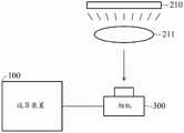
图1A为依据本发明实施例中的缺陷检测系统的方块图。图1B为依据本发明图1A的实施例中的利用相机拍摄近眼显示装置的图像的示意图。FIG. 1A is a block diagram of a defect detection system according to an embodiment of the present invention. FIG. 1B is a schematic diagram of using a camera to capture an image of the near-eye display device in the embodiment of FIG. 1A according to the present invention.
如图1A所示,缺陷检测系统10包括运算装置100、近眼显示装置200及相机300。运算装置100可为个人计算机、服务器或其他具有运算能力的装置,例如微处理器(MCU)、现场可编程门阵列(FPGA)、复杂可编程逻辑装置(CPLD)、专用集成电路(ASIC)等等,但本发明并不限于此。在一实施例中,运算装置100可包含处理器110、系统存储器130及非暂时性存储器140。非暂时性存储器140储存缺陷检测程序141,且处理器110可将缺陷检测程序141读取至系统存储器130并执行。缺陷检测程序141执行本发明的缺陷检测方法,其细节将详述于后。As shown in FIG. 1A , the
近眼显示装置200例如可为虚拟实境(virtual reality,VR)装置或增强现实(augmented reality,AR)的头戴式装置(head-mounted display,HMD)。为了便于说明,近眼显示装置200是以虚拟实境显示装置为例。The near-
近眼显示装置200例如可为头戴式显示器,且近眼显示装置200包括左眼显示面板210及对应的透镜211、右眼显示面板220及对应的透镜221、储存单元230、图像缓冲器240、显示控制器250、及一个或多个传输接口260、及外壳270。左眼显示面板210、透镜211、右眼显示面板220、透镜221以一预定光学排列方式安置于外壳270中,且外壳270可包括束带或其他辅助装置(未绘示)以供使用者戴于头上以透过近眼显示装置200观赏虚拟现实画面。The near-
左眼显示面板210及右眼显示面板220例如可为液晶(liquid crystal)面板、发光二极管(light-emitting diode)面板、有机发光二极管(organic light-emitting diode)面板、柔性显示面板(flexible display panel)或是其它类型的显示面板等,但本发明并不限于此。在一些实施例中,左眼显示面板210及右眼显示面板220可为不同且分离的显示面板,或是由同一显示面板所实现,且左眼显示面板210及右眼显示面板220为并排且平行的,两者之间并无角度差。在另一些实施例中,左眼显示面板210及右眼显示面板220为并排且不平行的,且两者之间具有角度差。The left-
透镜211及221例如可用一片菲涅耳透镜(Fresnel lens)或是多片菲涅耳透镜的组合所实现,也可以是由其他具有类似功能的光学透镜组合而成,但本发明并不限于此。The
传输接口260包括有线传输接口及/或无线传输接口,其中有线传输接口可包括:高清晰度多媒体接口(High Definition Multimedia Interface,HDMI)、显示端口(DisplayPort,DP)接口、嵌入式显示端口(embedded DisplayPort,eDP)、通用串行总线(Universal Serial Bus,USB)接口、USB Type-C接口、雷电(Thunderbolt)接口、数字视频接口(DVI)或其组合,且无线传输接口可包括:第五代移动通信技术(5th generationwireless system)、蓝牙(Bluetooth)、Wi-Fi、近场通信(NFC)接口等等,但本发明并不限于此。主机100可将图像信号(可包含左眼图像及右眼图像、或是平面图像)透过传输接口260传送至显示控制器250,且显示控制器250可将图像信号在左眼显示面板210及右眼显示面板220上播放。The
显示控制器250例如可为专用集成电路(application-specific integratedcircuit)、片上系统(System-on-chip)、处理器、或微控制器,但本发明并不限于此。储存单元230例如可为非暂时性存储器,例如只读存储器(ROM)、可擦除可编程只读存储器(EPROM)、电子擦除式可编程只读存储器(EEPROM)、闪存(flash memory)等等,但本发明并不限于此。储存单元230是用以储存近眼显示装置200相关的固件及测试画面。储存单元230例如可在显示控制器250的外部、或是可集成至显示控制器250中。图像缓冲器240例如可为动态随机存取存储器(DRAM),用以暂存欲播放的图像信号。The
相机300电性连接至运算装置100,且可在近眼显示装置200的观看区(或成像区)拍摄近眼显示装置200在左眼或右眼单侧的显示画面,其中上述观看区例如是使用者在使用近眼显示装置200观看图像时,使用者的双眼的观赏位置(或成像位置)。举例来说,左眼显示面板210可显示测试画面及参考画面,且上述画面经过透镜211后可被相机300所拍摄,如图1B所示。此外,右眼显示面板220也显示测试画面及参考画面,且上述画面经过透镜221后可被相机300所拍摄。需注意的是,近眼显示装置200在出厂前,左眼显示面板210及右眼显示面板220均需经过污点及亮点检测以滤除有问题的近眼显示装置200以确保近眼显示装置200的画面品质,其中污点(blemish)及亮点(bright dot)可统称为缺陷(defect)。The
图2A为依据本发明实施例中的测试图案图像的示意图。请同时参考图1A-1B图及图2A。FIG. 2A is a schematic diagram of a test pattern image according to an embodiment of the present invention. Please refer to FIGS. 1A-1B and FIG. 2A at the same time.
在一实施例中,近眼显示装置200可称为待测装置(device under test,DUT)。近眼显示装置200可先显示测试图案图像11,如第2图所示,其中测试图案图像11例如为覆盖有多个测试点12的全白图像。需注意的是,第2图所示的测试图案图像11为示意之用,在测试图案图像11中的测试点12可为任意分布,并不局限于规则排列。此外,测试点12可具有任意大小及形状,并不局限于方形测试点。测试点12也可具有任意亮度及颜色,并不局限于黑色(灰阶值=0)的测试点。相机300可拍摄近眼显示装置200的左眼显示面板210经过透镜211后所呈现的测试图案图像11以得到第一图像。In one embodiment, the near-
接着,近眼显示装置200再显示测试背景图像,其中上述测试背景图像例如可为完全无测试点的全白图像(例如红色/绿色/蓝色的亮度值均为255)。相机300可拍摄近眼显示装置200的左眼显示面板210经过透镜211后所呈现的测试背景图像以得到第二图像。在此实施例中,第一图像及第二图像可分别视为参考图像(reference image)及待测图像(DUTimage)。Next, the near-
选择性地,运算装置100可利用高动态范围图像的技术以得到参考图像及待测图像。举例来说,当近眼显示装置200显示测试图案图像时,相机300可使用不同的曝光设定(例如可调整曝光时间、图像感测器的灵敏度等等)以捕获多张曝光图像,并对上述曝光图像进行图像融合(image fusion)以得到第一图像。类似地,当近眼显示装置200显示全白图像时,相机300可使用不同的曝光值(例如可调整曝光时间、图像感测器的灵敏度等等)以捕获多张曝光图像,并对上述曝光图像进行图像融合(image fusion)以得到第二图像。第一图像及第二图像可分别视为参考图像(reference image)及待测图像(DUT image)。Optionally, the
运算装置100可从相机300取得所拍摄的参考图像及待测图像,并分别对参考图像及待测图像进行快速傅立叶转换(fast Fourier transform,FFT)以得到频域参考图像及频域待测图像。接着,运算装置100并对频域参考图像及频域待测图像应用带通滤波器(band-pass filter)以得到第一滤波图像及第二滤波图像,其中在第一滤波图像及第二滤波图像中的各像素的数值例如可为归一化(normalized)后的数值(介于0到1),且可反应出在原本的参考图像及待测图像中所对应的各像素的数值的变化程度。在一些实施例中,运算装置100可对频域参考图像及频域待测图像应用带通滤波器及一去莫列波纹滤波器(demoire filter)以得到第一滤波图像及第二滤波图像。本发明领域中具有通常知识者可使用公知的带通滤波器及去莫列波纹滤波器以应用于频域参考图像及频域待测图像,故其细节在此不再详述。The
若参考图像及待测图像中的特定像素为白色像素,且其周围像素均是白色像素,表示在特定像素的像素值在频域的变化极小,故经过快速傅立叶转换后,在频域参考图像及频域待测图像中的特定像素的位置的像素值会趋近于0。若参考图像及待测图像中的特定像素为黑色像素,且其周围像素均是白色像素,表示在特定像素的像素值在频域的变化极大,故经过快速傅立叶转换后,在频域参考图像及频域待测图像中的特定像素的位置的像素值会有较大的数值。If a specific pixel in the reference image and the image to be tested is a white pixel, and the surrounding pixels are all white pixels, it means that the pixel value of the specific pixel changes very little in the frequency domain. The pixel value of the position of a specific pixel in the image and the image to be tested in the frequency domain will approach 0. If a specific pixel in the reference image and the image to be tested is a black pixel, and the surrounding pixels are all white pixels, it means that the pixel value of the specific pixel changes greatly in the frequency domain. The pixel value of the position of a specific pixel in the image and the image to be measured in the frequency domain will have a larger value.
需特别注意的是,透镜211及221的视野(field of view,FOV)通常会大于90度,且透镜211及221视野越大会造成图像外围的成像品质越差(例如高频成分较少,即图像较不锐利),进而导致在滤波后图像的中心与外围的强度差异越大。It should be noted that the field of view (FOV) of the
此外,就算近眼显示装置200显示完全无测试点的全白图像(即测试背景图像),但相机300拍摄到的待测图像及参考图像中的各像素的数值可能会因为环境噪声或是相机300的图像感测器(未绘示)的噪声的影响而略为变动,故经过快速傅立叶转换后所得到的频域待测图像及频域参考图像中的许多非0的像素值即有可能是上述噪声所造成,且有可能造成图像的中心区域的高频噪声的像素值相对于图像的外围区域的真实讯号高,不利于检测相机300的整体视野范围中的污点(blemish)。再者,因为相机300是在近眼显示装置200组装完成后才进行上述拍摄操作,若近眼显示装置200中的左眼显示面板210及透镜211、或是右眼显示面板220及透镜221中有灰尘或污损,则也可能会影响到相机300拍摄到的待测图像。In addition, even if the near-
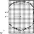
图2B为依据本发明图2A实施例中的第一滤波图像的示意图。FIG. 2B is a schematic diagram of the first filtered image in the embodiment of FIG. 2A according to the present invention.
在此实施例中,当运算装置100得到第一滤波图像后,即可得知在参考图像中的各个测试点在第一滤波图像中的对应的像素值。例如,参考图像中的测试点在第一滤波图像的中心区域的像素值为0.2且噪声的像素值为0.03,但是在第一滤波图像的外围区域的像素值为0.02且噪声的像素值为0.01。因此,运算装置100针对位于中心区域及外围区域中的不同的感兴趣区域设定不同的阈值以检测出中心区域及外围区域中的污点。In this embodiment, after the
详细而言,运算装置100可依据预定区域尺寸将第一滤波图像20及第二滤波图像分割为多个感兴趣区域(region of interest,ROI)21,其中各个感兴趣区域可具有任意形状及任意面积,并不局限于方形。此外,各个感兴趣区域可在第一滤波图像及第二滤波图像任意分布,意即各位置的感兴趣区域的面积及形状无固定格式。为了便于说明,在此实施例中,各个感兴趣区域21为固定尺寸(100x100像素)及固定形状(例如正方形),如图2B所示。若第一滤波图像20的分辨率为4000x3000像素,则经过上述图像分割处理,可得到40*30个感兴趣区域。Specifically, the
接着,运算装置100统计在第一滤波图像中的各个感兴趣区域的各像素的像素值以产生各个感兴趣区域对应的直方图(histogram)。举例来说,运算装置100可将在各个感兴趣区域中的各像素的像素值由低至高进行排列,并且设定预定截止比例。举例来说,若截止比例为99%,则表示运算装置100会计算各个感兴趣区域的直方图中在99%至100%的像素值的平均值,并设定该平均值为该感兴趣区域的阈值。在另一些实施例中,截止比例可反向设定为1%,且运算装置100会计算各个感兴趣区域的直方图中在前1%的像素值的平均值,并设定该平均值为该感兴趣区域的阈值。Next, the
图2C为第一滤波图像20的中心感兴趣区域21C的像素值的直方图,且运算装置100可计算出中心感兴趣区域21C的直方图在前1%像素值的平均值为0.08,并设定平均值为中心感兴趣区域21C相应的阈值。2C is a histogram of the pixel values of the central region of
当运算装置100依据上述方式计算出各个感兴趣区域相应的阈值后,即可建立阈值图(threshold map),其中阈值图为二维阵列,且其尺寸对应于第一滤波图像20中的感兴趣区域的数量。举例来说,若第一滤波图像20被分割为40*30个感兴趣区域,则阈值图即包含40x30个阈值,各阈值分别对应于各感兴趣区域。After the
当运算装置100已建立阈值图后,运算装置100即可将第二滤波图像与阈值图进行比对以产生各像素的判断结果。举例来说,若第二滤波图像同样被分割为40*30个感兴趣区域,则各个感兴趣区域中的各像素会分别与阈值图中对应位置的阈值进行比较。若在第二滤波图像的特定像素的像素值大于或等于对应感兴趣区域的阈值,则运算装置100会判断该特定像素为污点。因此,运算装置100可依据各像素的判断结果以建立近眼显示装置200的缺陷状态图(例如为二维阵列),其中缺陷状态图的各数值对应于待测图像的各像素的污点判断结果。举例来说,各像素的判断结果为二值化的数值,例如为0或1,其中1可表示对应的像素为污点,0则表示对应的像素为正常像素。After the
需特别注意的是,对于测试点来说,在第一滤波图像中,中心区域的测试点的像素值会比外围区域的测试点的像素值大,且经过直方图及阈值计算后,阈值图中的各数值的大小也与距离图像中心点的距离有关。意即越接近图像中心点的感兴趣区域,其相应的阈值会越大,越远离图像中心点的感兴趣区域,其相应的阈值会越小。因此,本发明的缺陷检测方法可更准确地判断出在近眼显示装置200中的缺陷(例如污点)。It should be noted that, for the test point, in the first filtered image, the pixel value of the test point in the central area will be larger than the pixel value of the test point in the peripheral area, and after the histogram and threshold calculation, the threshold map The size of each value in is also related to the distance from the center point of the image. That is, the closer the region of interest to the image center point, the larger the corresponding threshold value, and the farther the region of interest from the image center point, the smaller the corresponding threshold value. Therefore, the defect detection method of the present invention can more accurately determine defects (eg, stains) in the near-
本发明的缺陷检测系统还可用于检测近眼显示装置200的亮点。举例来说,亮点是显示面板上的常见缺陷,例如当显示面板应关闭特定像素时,该特定像素却恒亮,此时可将该特定像素称为亮点。随着缺陷程度不同,亮点的亮度也会不同。一般来说,显示面板的供应商可针对显示面板的亮点提供检测标准,例如在0到0.5的视野范围内的亮点亮度不能超过灰阶值55,且0.5到1.0的视野范围内的亮点亮度不能超过灰阶值120。上述视野范围的数值是指显示面板的中心点至左/右边缘及上/下边缘的距离比例。假定左眼显示面板210及右眼显示面板220的水平分辨率及垂直分辨率分别为W及H,若视野范围的数值为0到0.5,表示该视野范围是从显示面板的中心点左右延伸1/4W,且上下延伸1/4H,依此类推。The defect detection system of the present invention can also be used to detect bright spots of the near-
传统的亮点检测可分为人工目检及计算机视觉检测。然而,人工目标需要训练检测员,而且是人为主观检测,耗时且不精准。计算机视觉检测则是在显示面板显示固定灰阶的测试图像,例如检测目标为灰阶值为55的亮点,则可将测试图像的灰阶值设定为30,接着可透过工业相机拍摄显示面板播放测试图像的画面并利用计算机进行亮点检测。然而,利用传统计算机视觉技术进行亮点检测仍然会遇到污点检测的问题,且在近眼显示装置中,相机拍摄到的图像的外围区域会较模糊,并无法利用固定阈值的方式来判定亮点。Traditional bright spot detection can be divided into manual visual inspection and computer vision detection. However, artificial targets require training of detectors and are subjectively detected, which is time-consuming and inaccurate. Computer vision inspection is to display a test image with a fixed grayscale on the display panel. For example, if the detection target is a bright spot with a grayscale value of 55, the grayscale value of the test image can be set to 30, and then it can be captured and displayed by an industrial camera. The panel plays the picture of the test image and uses the computer for bright spot detection. However, using traditional computer vision technology for bright spot detection still encounters the problem of stain detection, and in a near-eye display device, the peripheral area of the image captured by the camera will be blurred, and a fixed threshold cannot be used to determine the bright spot.
图3为依据本发明实施例中用于亮点检测的测试图案图像的示意图。FIG. 3 is a schematic diagram of a test pattern image for bright spot detection according to an embodiment of the present invention.
在一实施例中,本发明中缺陷检测系统也可用于亮点检测。因为相机300是在近眼显示装置200组装完成后才进行上述拍摄操作,所以若近眼显示装置200中的左眼显示面板210及透镜211、或是右眼显示面板220及透镜221中有灰尘或污损(即污点),都会影响到亮点检测的结果。In one embodiment, the defect detection system of the present invention can also be used for bright spot detection. Because the
举例来说,在此实施例中,用于检测亮点的测试图案图像30可包括中心区域31及外围区域32。中心区域31例如是0至0.5的视野范围的区域,且其灰阶值可固定为55(非限定)。外围区域32例如是0.5至1的视野范围的区域,且其灰阶值可固定为120(非限定)。此外,测试图案图像30同样具有多个测试点33覆盖其上。需注意的是,在测试图案图像30中的测试点可具有任意的亮度值(或灰阶值),且可具有任意颜色、尺寸及分布。相机300可拍摄近眼显示装置200的左眼显示面板210经过透镜211后所呈现的测试图案图像30以得到第一图像。For example, in this embodiment, the
此外,近眼显示装置200再显示完全无测试点的测试背景图像,且相机300可拍摄近眼显示装置200的左眼显示面板210经过透镜211后所呈现的上述测试背景图像以得到第二图像。In addition, the near-
接着,运算装置100可对第一图像及第二图像分别进行图像预处理以得到用于亮点检测的参考图像及待测图像。举例来说,运算装置100可对第一图像进行图像模糊化处理(image blurring process)以得到模糊化第一图像(blurred first image),并且将第一图像减去模糊化第一图像以得到第一差值图像。Next, the
详细而言,在进行亮点检测之前,运算装置100需要先排除近眼显示装置200中的污点。若近眼显示装置200中的左眼显示面板210及透镜211、或是右眼显示面板220及透镜221中有灰尘或污损(即污点),则污点在第一图像中对应的一个或多个像素的像素值会接近0,故污点的像素值相对于周围像素的灰阶值(例如55或120)的变化极大。此外,上述图像模糊化处理例如可对第一图像中的各像素及其周围像素应用低通滤波器,例如可采用一阶或多阶的有限响应滤波器(finite impulse response filter)、高斯滤波器等等,但本发明并不限于此。因此,在第一图像中的污点像素及其周围像素的像素值可被平滑化(smoothed),但是在平滑化后的污点像素的灰阶值会略小于污点的对应位置的背景像素的灰阶值。当运算装置100将第一图像减去模糊化第一图像后,在污点像素的位置的差值会小于0,故运算装置100可从第一差值图像中找出污点像素的位置,并且将第一差值图像中小于0的像素进行像素修剪处理(pixel clipping process)以得到第一修剪差值图像,例如可将第一差值图像中小于0的像素由在第一图像中的平滑区(即灰阶值无剧烈变化的区域)的差值像素取代、或是将第一差值图像中小于0的像素直接设定为0以得到第一修剪差值图像。In detail, before performing bright spot detection, the
类似地,运算装置100可对第二图像进行图像模糊化处理(image blurringprocess)以得到模糊化第二图像(blurred first image),并且将第二图像减去模糊化第二图像以得到第二差值图像。运算装置100可从第二差值图像中找出污点像素的位置,并且将第二差值图像中小于0的像素进行修剪处理(clipping process)以得到第二修剪差值图像,例如可将第二差值图像中小于0的像素由在第二图像中的平滑区(即灰阶值无剧烈变化的区域)的差值像素取代、或是将第二差值图像中小于0的像素直接设定为0以得到第二修剪差值图像。在此实施例中,第一修剪差值图像及第二修剪差值图像即可视为在图2A-2C实施例的缺陷检测流程中的参考图像及待测图像。Similarly, the
因此,当运算装置100经由上述流程以得到参考图像及待测图像后,运算装置100即可参考图像及待测图像执行在图2A-2C实施例的缺陷检测流程,且最后产生的缺陷状态图的各数值对应于待测图像的各像素的亮点判断结果,且已排除污点。举例来说,各像素的判断结果为二值化的数值,例如为0或1,其中1可表示对应的像素为亮点,0则表示对应的像素为正常像素。Therefore, after the
图4A为依据本发明实施例中的用于近眼显示装置的缺陷检测方法的流程图。4A is a flowchart of a defect detection method for a near-eye display device according to an embodiment of the present invention.
在步骤S410,依据相机300对显示面板分别播放测试图案图像及测试背景图像时经过菲涅耳透镜进行拍摄的第一图像及第二图像以得到参考图像及待测图像。举例来说,近眼显示装置200的显示面板(可为左眼显示面板210或右眼显示面板220)可播放测试图案图像及测试背景图像,且相机300可拍摄该显示面板经过菲涅耳透镜(例如为对应的透镜211或221)所呈现的测试图案图像及测试背景图像以得到第一图像及第二图像。在一些实施例中,第一图像及第二图像是由使用不同曝光值的多张曝光图像进行图像融合所得到的高动态范围(HDR)图像。在污点检测流程中,运算装置100可将第一图像及第二图像直接设定为参考图像及待测图像。在亮点检测流程中,步骤S410可分为步骤S401至S404,其细节可参考图4B的流程。In step S410, the first image and the second image captured by the Fresnel lens when the test pattern image and the test background image are respectively played on the display panel by the
在步骤S420,对参考图像及待测图像分别执行快速傅立叶转换以得到频域参考图像及频域待测图像。In step S420, fast Fourier transform is performed on the reference image and the image to be tested, respectively, to obtain the reference image in the frequency domain and the image to be tested in the frequency domain.
在步骤S430,对频域参考图像及频域待测图像应用带通滤波器以得到第一滤波图像及第二滤波图像。在第一滤波图像及第二滤波图像中的各像素的数值例如可为归一化(normalized)后的数值(介于0到1),且可反应出在原本的参考图像及待测图像中所对应的各像素的数值的变化程度。在一些实施例中,运算装置100可对频域参考图像及频域待测图像应用带通滤波器及一去莫列波纹滤波器(demoire filter)以得到第一滤波图像及第二滤波图像。In step S430, a bandpass filter is applied to the frequency domain reference image and the frequency domain image to be tested to obtain a first filtered image and a second filtered image. The value of each pixel in the first filtered image and the second filtered image can be, for example, a normalized value (between 0 and 1), which can be reflected in the original reference image and the image to be tested The degree of change in the value of the corresponding pixels. In some embodiments, the
在步骤S440,将第一滤波图像及第二滤波图像分别分割为多个第一感兴趣区域及多个第二感兴趣区域,其中所述多个第一感兴趣区域对应所述多个第二感兴趣区域。In step S440, the first filtered image and the second filtered image are respectively divided into a plurality of first regions of interest and a plurality of second regions of interest, wherein the plurality of first regions of interest correspond to the plurality of second regions of interest area of interest.
在步骤S450,统计各个第一感兴趣区域中的像素值以得到相应于各个第一感兴趣区域的直方图,并且计算在各个第一感兴趣区域的直方图中在预定截止比例以上的像素值的平均值以作为各个第一感兴趣区域相应的阈值。In step S450, count the pixel values in each of the first regions of interest to obtain a histogram corresponding to each of the first regions of interest, and calculate pixel values in the histogram of each of the first regions of interest that are above a predetermined cutoff ratio The average value of is used as the corresponding threshold for each first region of interest.
在步骤S460,依据在第一滤波图像的各个第一感兴趣区域相应的阈值以建立阈值图,并将在第二滤波图像的各个第二感兴趣区域中的各像素与阈值图中的相应阈值进行比较以产生在第二滤波图像的各像素相应的判断结果。举例来说,各个感兴趣区域中的各像素会分别与阈值图中对应位置的阈值进行比较。若在第二滤波图像的特定像素的像素值大于或等于对应感兴趣区域的阈值,则运算装置100会判断该特定像素为污点。In step S460, a threshold map is established according to the corresponding thresholds in each first region of interest in the first filtered image, and each pixel in each second region of interest in the second filtered image is compared with the corresponding threshold in the threshold map The comparison is performed to generate corresponding judgment results for each pixel of the second filtered image. For example, each pixel in each region of interest is compared with the threshold value at the corresponding position in the threshold value map. If the pixel value of a specific pixel in the second filtered image is greater than or equal to the threshold value corresponding to the region of interest, the
在步骤S470,依据在第二滤波图像的各像素相应的判断结果以建立近眼显示装置200的缺陷状态图。举例来说,缺陷状态图的各数值对应于待测图像的各像素的污点判断结果。举例来说,各像素的判断结果为二值化的数值,例如为0或1,其中1可表示对应的像素为污点,0则表示对应的像素为正常像素。In step S470, a defect state diagram of the near-
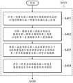
图4B为本发明图4A实施例中的步骤S410的流程图。请同时参考图3及图4A-4B。FIG. 4B is a flowchart of step S410 in the embodiment of FIG. 4A of the present invention. Please also refer to FIG. 3 and FIGS. 4A-4B.
在亮点检测流程中,步骤S410可分为步骤S401至S404。即,运算装置100可对第一图像及第二图像分别进行图像预处理以得到用于亮点检测的参考图像及待测图像。In the bright spot detection process, step S410 can be divided into steps S401 to S404. That is, the
在步骤S401,对第一图像及第二图像进行图像模糊化处理以得到模糊化第一图像及模糊化第二图像。举例来说,在进行亮点检测之前,运算装置100需要先排除近眼显示装置200中的污点。若近眼显示装置200中的左眼显示面板210及透镜211、或是右眼显示面板220及透镜221中有灰尘或污损(即污点),则污点在第一图像中对应的一个或多个像素的像素值会接近0,故污点的像素值相对于周围像素的灰阶值(例如55或120)的变化极大。经过图像模糊化处理后,在第一图像及第二图像中的污点像素及其周围像素的像素值可被平滑化(smoothed),但是在平滑化后的像素的灰阶值会略小于污点的对应位置的像素的灰阶值。In step S401, image blurring processing is performed on the first image and the second image to obtain a blurred first image and a blurred second image. For example, before performing bright spot detection, the
在步骤S402,将第一图像及第二图像分别减去模糊化第一图像及模糊化第二图像以得到第一差值图像及第二差值图像。举例来说,平滑化后的污点像素的灰阶值会略小于污点的对应位置的背景像素的灰阶值。因此,运算装置100可判断在第一差值图像及第二差值图像中小于0的像素即为污点像素的位置。In step S402, the blurred first image and the blurred second image are respectively subtracted from the first image and the second image to obtain a first difference image and a second difference image. For example, the grayscale value of the smoothed stain pixel is slightly smaller than the grayscale value of the background pixel at the corresponding position of the stain. Therefore, the
在步骤S403,将第一差值图像及第二差值图像中的小于0的像素值进行像素修剪处理以分别得到第一修剪差值图像及第二修剪差值图像。为了要排除污点对于亮点检测的图像,运算装置100可将将第一差值图像及第二差值图像中的小于0的像素值在第一图像中的平滑区(即灰阶值无剧烈变化的区域)的差值像素取代、或是将第一差值图像中小于0的像素直接设定为0。In step S403, pixel values less than 0 in the first difference image and the second difference image are subjected to pixel trimming processing to obtain the first trimmed difference image and the second trimmed difference image, respectively. In order to exclude stains from the image detected by the bright spot, the
在步骤S404,将第一修剪差值图像及第二修剪差值图像设定为参考图像及待测图像。In step S404, the first trimmed difference image and the second trimmed difference image are set as the reference image and the image to be tested.
综上所述,本发明是提供一种运算装置及用于近眼显示装置的缺陷检测方法,其可解决近眼显示装置所显示的图像在外围区域会有图像模糊而造成污点检测的误判的情况,并且可搭配不同的测试图案图像以调整不同的亮点检测标准。因此,本发明所提供的运算装置及用于近眼显示装置的缺陷检测方法可更精确地判断出近眼显示装置的缺陷(包含污点及亮点),以确保近眼显示装置的出厂品质。To sum up, the present invention provides a computing device and a defect detection method for a near-eye display device, which can solve the situation that the image displayed by the near-eye display device may be blurred in the peripheral area, resulting in false judgment of stain detection. , and can be matched with different test pattern images to adjust different bright spot detection standards. Therefore, the computing device and the defect detection method for a near-eye display device provided by the present invention can more accurately determine the defects (including stains and bright spots) of the near-eye display device, so as to ensure the delivery quality of the near-eye display device.
本发明的方法,或特定型态或其部份,可以以程序码的型态包含于实体媒体,如软盘、光盘片、硬盘、或是任何其他机器可读取(如计算机可读取)储存介质,其中,当程序码被机器,如计算机载入且执行时,此机器变成用以参与本发明的装置或系统。本发明的方法、系统与装置也可以以程序码型态透过一些传送介质,如电线或电缆、光纤、或是任何传输型态进行传送,其中,当程序码被机器,如计算机接收、载入且执行时,此机器变成用以参与本发明的装置或系统。当在一般用途处理器实施时,程序码结合处理器提供操作类似于应用特定逻辑电路的独特装置。The methods of the present invention, or specific forms or portions thereof, may be embodied in the form of program code on a physical medium such as a floppy disk, an optical disk, a hard disk, or any other machine-readable (eg, computer-readable) storage. A medium wherein, when the program code is loaded and executed by a machine, such as a computer, the machine becomes an apparatus or system for participating in the present invention. The method, system and apparatus of the present invention can also be transmitted in the form of program code through some transmission medium, such as wire or cable, optical fiber, or any transmission type, wherein when the program code is received by a machine, such as a computer, loaded When entered and executed, the machine becomes a device or system for participating in the present invention. When implemented in a general-purpose processor, the program code combines with the processor to provide a unique apparatus that operates analogously to application-specific logic circuits.
本发明虽以较佳实施例揭露如上,然其并非用以限定本发明的范围,任何本领域普通技术人员,在不脱离本发明的精神和范围内,当可做些许的更动与润饰,因此本发明的保护范围当视后附的权利要求书所界定者为准。Although the present invention is disclosed above with preferred embodiments, it is not intended to limit the scope of the present invention. Any person of ordinary skill in the art can make some changes and modifications without departing from the spirit and scope of the present invention. Therefore, the protection scope of the present invention should be defined by the appended claims.
[符号说明][Symbol Description]
10:缺陷检测系统10: Defect detection system
11:测试图案图像11: Test Pattern Image
12:测试点12: Test point
20:第一滤波图像20: First filtered image
21:感兴趣区域21: Region of Interest
21C:中心感兴趣区域21C: Central Region of Interest
30:测试图案图像30: Test Pattern Image
31:中心区域31: Central Area
32:外围区域32: Peripheral area
33:测试点33: Test Points
100:运算装置100: Computing device
110:处理器110: Processor
130:系统存储器130: System memory
140:非暂时性存储器140: Non-transitory memory
141:缺陷检测程序141: Defect Detection Procedures
200:近眼显示装置200: Near-Eye Display Devices
210:左眼显示面板210: Left eye display panel
211、221:透镜211, 221: Lenses
220:右眼显示面板220: Right eye display panel
230:储存单元230: Storage Unit
240:图像缓冲器240: Image buffer
250:显示控制器250: Display Controller
260:传输接口260: Transmission interface
270:外壳270: Shell
300:相机300: Camera
S401-S404、S410-S470:步骤S401-S404, S410-S470: Steps
Claims (10)
Translated fromChineseApplications Claiming Priority (2)
| Application Number | Priority Date | Filing Date | Title |
|---|---|---|---|
| TW109146757ATWI751869B (en) | 2020-12-30 | 2020-12-30 | Computation apparatus and method of detecting defects for near-eye display |
| TW109146757 | 2020-12-30 |
Publications (2)
| Publication Number | Publication Date |
|---|---|
| CN114764779Atrue CN114764779A (en) | 2022-07-19 |
| CN114764779B CN114764779B (en) | 2024-10-11 |
Family
ID=80809213
Family Applications (1)
| Application Number | Title | Priority Date | Filing Date |
|---|---|---|---|
| CN202110074515.6AActiveCN114764779B (en) | 2020-12-30 | 2021-01-20 | Operation device and defect detection method for near-eye display device |
Country Status (3)
| Country | Link |
|---|---|
| US (1) | US11748856B2 (en) |
| CN (1) | CN114764779B (en) |
| TW (1) | TWI751869B (en) |
Cited By (1)
| Publication number | Priority date | Publication date | Assignee | Title |
|---|---|---|---|---|
| WO2025175565A1 (en)* | 2024-02-23 | 2025-08-28 | Jade Bird Display (shanghai) Limited | Method and system for correcting nonuniformity of near-eye display |
Families Citing this family (4)
| Publication number | Priority date | Publication date | Assignee | Title |
|---|---|---|---|---|
| KR20230030126A (en)* | 2021-08-24 | 2023-03-06 | 삼성디스플레이 주식회사 | Display device and method of driving the same |
| CN115330610B (en)* | 2022-07-22 | 2025-06-13 | 北京达佳互联信息技术有限公司 | Image processing method, device, electronic device and storage medium |
| US20240070056A1 (en)* | 2022-08-30 | 2024-02-29 | Baidu Usa Llc | Manufacture test system for computation hardware used in driverless vehicle |
| WO2024248866A1 (en)* | 2023-06-01 | 2024-12-05 | Google Llc | Image device error detector |
Citations (6)
| Publication number | Priority date | Publication date | Assignee | Title |
|---|---|---|---|---|
| US20030086608A1 (en)* | 2001-07-17 | 2003-05-08 | Amnis Corporation | Computational methods for the segmentation of images of objects from background in a flow imaging instrument |
| US20110176024A1 (en)* | 2010-01-15 | 2011-07-21 | Samsung Electronics Co., Ltd. | Image Fusion Apparatus and Method |
| KR20150064469A (en)* | 2013-12-03 | 2015-06-11 | 삼성전자주식회사 | Method, apparatus and storage medium for compensating for defect pixel of display |
| US20180078123A1 (en)* | 2015-06-03 | 2018-03-22 | Olympus Corporation | Image processing device, endoscope device, and image processing method |
| US9979956B1 (en)* | 2016-06-09 | 2018-05-22 | Oculus Vr, Llc | Sharpness and blemish quality test subsystem for eyecup assemblies of head mounted displays |
| CN109919933A (en)* | 2019-03-08 | 2019-06-21 | 歌尔股份有限公司 | VR equipment and its screen detection method, device, and computer-readable storage medium |
Family Cites Families (7)
| Publication number | Priority date | Publication date | Assignee | Title |
|---|---|---|---|---|
| US5513275A (en)* | 1993-01-12 | 1996-04-30 | Board Of Trustees Of The Leland Stanford Junior University | Automated direct patterned wafer inspection |
| JP4061289B2 (en)* | 2004-04-27 | 2008-03-12 | 独立行政法人科学技術振興機構 | Image inspection method and apparatus |
| CN101532926A (en)* | 2008-12-12 | 2009-09-16 | 齐齐哈尔华工机床制造有限公司 | On-line vision detecting system for automatic impact specimen processing device and image processing method thereof |
| CN104091341B (en)* | 2014-07-18 | 2018-03-30 | 厦门美图之家科技有限公司 | A kind of image fuzzy detection method based on conspicuousness detection |
| KR102489882B1 (en)* | 2016-09-16 | 2023-01-18 | 밸브 코포레이션 | Optical systems for head-worn display systems |
| JP2020144691A (en)* | 2019-03-07 | 2020-09-10 | 株式会社Screenホールディングス | Model color determination method, inspection device, inspection method, and program |
| US11676293B2 (en)* | 2020-11-25 | 2023-06-13 | Meta Platforms Technologies, Llc | Methods for depth sensing using candidate images selected based on an epipolar line |
- 2020
- 2020-12-30TWTW109146757Apatent/TWI751869B/enactive
- 2021
- 2021-01-20CNCN202110074515.6Apatent/CN114764779B/enactiveActive
- 2021-03-29USUS17/215,835patent/US11748856B2/enactiveActive
Patent Citations (6)
| Publication number | Priority date | Publication date | Assignee | Title |
|---|---|---|---|---|
| US20030086608A1 (en)* | 2001-07-17 | 2003-05-08 | Amnis Corporation | Computational methods for the segmentation of images of objects from background in a flow imaging instrument |
| US20110176024A1 (en)* | 2010-01-15 | 2011-07-21 | Samsung Electronics Co., Ltd. | Image Fusion Apparatus and Method |
| KR20150064469A (en)* | 2013-12-03 | 2015-06-11 | 삼성전자주식회사 | Method, apparatus and storage medium for compensating for defect pixel of display |
| US20180078123A1 (en)* | 2015-06-03 | 2018-03-22 | Olympus Corporation | Image processing device, endoscope device, and image processing method |
| US9979956B1 (en)* | 2016-06-09 | 2018-05-22 | Oculus Vr, Llc | Sharpness and blemish quality test subsystem for eyecup assemblies of head mounted displays |
| CN109919933A (en)* | 2019-03-08 | 2019-06-21 | 歌尔股份有限公司 | VR equipment and its screen detection method, device, and computer-readable storage medium |
Cited By (1)
| Publication number | Priority date | Publication date | Assignee | Title |
|---|---|---|---|---|
| WO2025175565A1 (en)* | 2024-02-23 | 2025-08-28 | Jade Bird Display (shanghai) Limited | Method and system for correcting nonuniformity of near-eye display |
Also Published As
| Publication number | Publication date |
|---|---|
| US20220207664A1 (en) | 2022-06-30 |
| TWI751869B (en) | 2022-01-01 |
| US11748856B2 (en) | 2023-09-05 |
| TW202226828A (en) | 2022-07-01 |
| CN114764779B (en) | 2024-10-11 |
Similar Documents
| Publication | Publication Date | Title |
|---|---|---|
| TWI751869B (en) | Computation apparatus and method of detecting defects for near-eye display | |
| CN109752394B (en) | High-precision detection method and system for defects of display screen | |
| US10255662B2 (en) | Image processing method for detail enhancement and noise reduction | |
| CN102413354B (en) | Automatic optical detection method, device and system of mobile phone camera module | |
| CN111031311B (en) | Imaging quality detection method and device, electronic equipment and readable storage medium | |
| TWI759669B (en) | Method and system for inspecting display image | |
| US8238640B2 (en) | Display testing apparatus and method | |
| CN107920246B (en) | Inclination testing method and device for camera module | |
| CN106412573A (en) | Method and device for detecting lens stain | |
| GB2454096A (en) | Detecting Light Source Direction from Single Image | |
| US9332247B2 (en) | Image processing device, non-transitory computer readable recording medium, and image processing method | |
| CN111445452B (en) | Defect detection method and device of electronic product and computer readable storage medium | |
| CN102739952B (en) | Multi-view image capturing method and application system thereof | |
| CN113053324A (en) | Backlight control method, device, equipment, system and storage medium | |
| JPWO2014013792A1 (en) | Noise evaluation method, image processing apparatus, imaging apparatus, and program | |
| CN115345774A (en) | Method and system for fusing infrared image and visible light image | |
| CN114620030A (en) | Parking performance testing method and device, server and product | |
| JP2005331929A5 (en) | ||
| KR20180108714A (en) | Nonuniform evaluation method and nonuniform evaluation device | |
| US10624536B2 (en) | Virtual reality-based ophthalmic inspection system and inspection method thereof | |
| CN105427315B (en) | Digital instrument image position testing method and device | |
| CN114689605A (en) | Display detection method, device, equipment and medium based on machine vision | |
| CN118111997A (en) | LED large screen quality inspection method and equipment based on computer vision | |
| TWI677231B (en) | Method and system for inspecting display apparatus | |
| CN116993654B (en) | Camera module defect detection method, device, equipment, storage medium and product |
Legal Events
| Date | Code | Title | Description |
|---|---|---|---|
| PB01 | Publication | ||
| PB01 | Publication | ||
| SE01 | Entry into force of request for substantive examination | ||
| SE01 | Entry into force of request for substantive examination | ||
| GR01 | Patent grant | ||
| GR01 | Patent grant |