CN114762635A - Valve clamping device and valve clamping system with full fitting - Google Patents
Valve clamping device and valve clamping system with full fittingDownload PDFInfo
- Publication number
- CN114762635A CN114762635ACN202110057563.4ACN202110057563ACN114762635ACN 114762635 ACN114762635 ACN 114762635ACN 202110057563 ACN202110057563 ACN 202110057563ACN 114762635 ACN114762635 ACN 114762635A
- Authority
- CN
- China
- Prior art keywords
- clamping device
- valve
- valve clamping
- adjusting
- adjustment
- Prior art date
- Legal status (The legal status is an assumption and is not a legal conclusion. Google has not performed a legal analysis and makes no representation as to the accuracy of the status listed.)
- Granted
Links
Images


Classifications
- A—HUMAN NECESSITIES
- A61—MEDICAL OR VETERINARY SCIENCE; HYGIENE
- A61F—FILTERS IMPLANTABLE INTO BLOOD VESSELS; PROSTHESES; DEVICES PROVIDING PATENCY TO, OR PREVENTING COLLAPSING OF, TUBULAR STRUCTURES OF THE BODY, e.g. STENTS; ORTHOPAEDIC, NURSING OR CONTRACEPTIVE DEVICES; FOMENTATION; TREATMENT OR PROTECTION OF EYES OR EARS; BANDAGES, DRESSINGS OR ABSORBENT PADS; FIRST-AID KITS
- A61F2/00—Filters implantable into blood vessels; Prostheses, i.e. artificial substitutes or replacements for parts of the body; Appliances for connecting them with the body; Devices providing patency to, or preventing collapsing of, tubular structures of the body, e.g. stents
- A61F2/02—Prostheses implantable into the body
- A61F2/24—Heart valves ; Vascular valves, e.g. venous valves; Heart implants, e.g. passive devices for improving the function of the native valve or the heart muscle; Transmyocardial revascularisation [TMR] devices; Valves implantable in the body
- A61F2/2442—Annuloplasty rings or inserts for correcting the valve shape; Implants for improving the function of a native heart valve
- A61F2/2466—Delivery devices therefor
- A—HUMAN NECESSITIES
- A61—MEDICAL OR VETERINARY SCIENCE; HYGIENE
- A61F—FILTERS IMPLANTABLE INTO BLOOD VESSELS; PROSTHESES; DEVICES PROVIDING PATENCY TO, OR PREVENTING COLLAPSING OF, TUBULAR STRUCTURES OF THE BODY, e.g. STENTS; ORTHOPAEDIC, NURSING OR CONTRACEPTIVE DEVICES; FOMENTATION; TREATMENT OR PROTECTION OF EYES OR EARS; BANDAGES, DRESSINGS OR ABSORBENT PADS; FIRST-AID KITS
- A61F2/00—Filters implantable into blood vessels; Prostheses, i.e. artificial substitutes or replacements for parts of the body; Appliances for connecting them with the body; Devices providing patency to, or preventing collapsing of, tubular structures of the body, e.g. stents
- A61F2/02—Prostheses implantable into the body
- A61F2/24—Heart valves ; Vascular valves, e.g. venous valves; Heart implants, e.g. passive devices for improving the function of the native valve or the heart muscle; Transmyocardial revascularisation [TMR] devices; Valves implantable in the body
- A61F2/2442—Annuloplasty rings or inserts for correcting the valve shape; Implants for improving the function of a native heart valve
- A61F2/246—Devices for obstructing a leak through a native valve in a closed condition
Landscapes
- Health & Medical Sciences (AREA)
- Cardiology (AREA)
- Oral & Maxillofacial Surgery (AREA)
- Transplantation (AREA)
- Engineering & Computer Science (AREA)
- Biomedical Technology (AREA)
- Heart & Thoracic Surgery (AREA)
- Vascular Medicine (AREA)
- Life Sciences & Earth Sciences (AREA)
- Animal Behavior & Ethology (AREA)
- General Health & Medical Sciences (AREA)
- Public Health (AREA)
- Veterinary Medicine (AREA)
- Prostheses (AREA)
Abstract
Translated fromChinese
Description
Translated fromChinese技术领域technical field
本申请涉及介入式医疗器械技术领域,尤其涉及一种贴合充分的瓣膜夹合装置和瓣膜夹合系统。The present application relates to the technical field of interventional medical devices, and in particular, to a valve clamping device and a valve clamping system that fit well.
背景技术Background technique
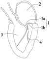
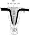
请参阅图1,二尖瓣1是位于心脏左心房2与左心室3之间的单向阀,正常健康的二尖瓣1可以控制血液从左心房2流到左心室3,同时避免血液从左心室3流到左心房2。二尖瓣1包括一对瓣叶,称为前叶1a及后叶1b。前叶1a及后叶1b通过腱索4固定于左心室3的乳头肌上。正常情况下,心脏左心室3收缩时,前叶1a和后叶1b的边缘完全对合,避免血液从左心室3流到左心房2。请参阅图2,当二尖瓣1的瓣叶或其相关结构发生器质性改变或功能性改变时,如腱索4部分断裂,二尖瓣1的前叶1a和后叶1b对合不良,由此,当心脏左心室3收缩时,二尖瓣1不能完全关闭,导致血液从左心室3反流至左心房2,从而引起一系列的病理生理改变,称为“二尖瓣反流”。Please refer to Figure 1, the
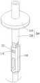
介入式二尖瓣夹合术是指通过向二尖瓣植入瓣膜夹合装置,使用一对可闭合的钳臂将前叶和后叶拉向彼此,减小或消除瓣叶间隙从而治疗二尖瓣反流。图3及图4示出了一种现有的瓣膜夹合装置,该瓣膜夹合装置90在两个钳臂91中增加了弹性网93,每侧的瓣叶L被分别夹持在一侧钳臂91和弹性网93的一侧之间,通过弹性网93的变形来适应瓣叶的间距,从而调节钳臂91对瓣叶L的牵拉程度。该弹性网93的一端931通过钢套等封头固定连接支撑部95的第一端951(第一端951指支撑部95靠近两钳臂91转动连接部位的一端),弹性网93的另一端933为活动围绕支撑部95的自由端。在两钳臂91闭合的时候,弹性网93受到挤压而变形,由于封头97限制了弹性网93的一端931的轴向活动,弹性网93在轴向上会朝向其自由端933伸长,同时弹性网93被两钳臂91挤压的两侧会在径向上回缩,弹性网93的自由端933及其附近的部位受回缩部位的影响而逐渐朝向弹性网93的中轴线收拢,这就使得弹性网93的自由端933及其附近的部位与瓣叶L之间存在径向间隙X,即瓣叶L无法贴合弹性网93的自由端933及其附近的部位,瓣叶L与弹性网93的弹性贴合面积有限,相应地,弹性网93的自由端933及其附近的部位不能够为瓣叶L提供径向支撑力,有可能导致钳臂91和弹性网93对瓣叶L的夹持力不足以牢靠地夹持住瓣叶L,存在瓣叶L从钳臂91和弹性网93之间脱落的风险,影响瓣膜夹合装置的植入稳定性;同时,弹性网93的自由端933及其附近的部位与瓣叶L之间的径向间隙X允许自夹合间隙反流的血液透过,影响反流治疗效果。Interventional mitral valve clipping refers to the treatment of the mitral valve by implanting a valve clipping device into the mitral valve, using a pair of closable clamp arms to draw the anterior and posterior leaflets toward each other, reducing or eliminating the leaflet gap. cusp regurgitation. Figures 3 and 4 show an existing valve clamping device. The
发明内容SUMMARY OF THE INVENTION
为了解决上述技术问题或者至少部分地解决上述技术问题,本申请提供一种贴合充分的瓣膜夹合装置和瓣膜夹合系统。In order to solve the above technical problems or at least partially solve the above technical problems, the present application provides a valve clamping device and valve clamping system that fit well.
第一方面,本申请提供了一种贴合充分的瓣膜夹合装置,包括:In a first aspect, the present application provides a fully fitted valve clamping device, comprising:
支撑部,所述支撑部具有一定轴向长度,且包括相对设置的第一端和第二端;a support part, the support part has a certain axial length and includes a first end and a second end arranged oppositely;
调节部,所述调节部包括相对设置的第一端和第二端、以及位于所述第一端和所述第二端之间的自扩展主体;所述调节部的第一端活动套设在所述支撑部的外侧,所述调节部的第二端套设在所述支撑部的外侧并与所述支撑部固定连接,所述调节部的第一端位于所述支撑部的第一端与所述调节部的第二端之间;an adjustment part, the adjustment part includes a first end and a second end arranged oppositely, and a self-expanding body located between the first end and the second end; the first end of the adjustment part is movably sleeved On the outside of the support part, the second end of the adjustment part is sleeved on the outside of the support part and is fixedly connected with the support part, and the first end of the adjustment part is located at the first end of the support part between the end and the second end of the adjusting portion;
夹合部,所述夹合部设于所述支撑部的外侧并可相对于所述调节部展开或闭合。The clamping part is arranged on the outer side of the supporting part and can be unfolded or closed relative to the adjusting part.
第二方面,本申请提供了一种瓣膜夹合系统,包括上述贴合充分的瓣膜夹合装置、以及输送装置,其中,所述输送装置包括:具有一定轴向长度的推送鞘管及活动地穿装在所述推送鞘管中的芯轴,所述推送鞘管与所述支撑部之间可拆卸连接,所述芯轴用于驱动所述夹合部的展开和闭合。In a second aspect, the present application provides a valve clamping system, including the above-mentioned fully fitted valve clamping device, and a delivery device, wherein the delivery device includes: a pusher sheath having a certain axial length and a movable A mandrel inserted in the push sheath tube is detachably connected between the push sheath tube and the support part, and the mandrel is used to drive the expansion and closing of the clamping part.
本申请提供的瓣膜夹合装置和瓣膜夹合系统,将所述调节部的第二端套设在所述支撑部的外侧并与所述支撑部固定连接,将所述调节部的第一端活动套设在所述支撑部的外侧,以及将所述调节部的第一端设于所述支撑部的第一端与所述调节部的第二端之间,当所述夹合部相对所述调节部闭合以将瓣叶夹持在所述调节部的自扩展主体与所述夹合部之间时,所述调节部的第二端及其附近的部分自扩展主体的轴向活动受限,自扩展主体在轴向上会朝向调节部的第一端伸长,同时所述自扩展主体受所述夹合部的挤压会在径向上回缩,伴随着所述调节部的第一端朝向瓣叶的瓣缘延伸,自扩展主体朝着调节部的第一端逐渐朝向调节部的中轴线收拢,调节部第二端附近的部分自扩展主体与瓣叶之间能够紧密贴合而不存在径向间隙,相比于现有技术能够增加瓣叶与调节部的贴合面积,使得瓣叶与调节部充分贴合,相应地,所述调节部的第二端及其附近的部分自扩展主体能够为瓣叶提供径向支撑力,进而提高夹持力以牢靠地夹持住瓣叶,降低瓣叶从夹合部与调节部之间脱落的风险,提升瓣膜夹合装置的植入稳定性;同时,调节部第二端附近的部分自扩展主体与瓣叶之间的紧密贴合能够封堵自夹合间隙反流的血液,优化反流治疗效果。In the valve clamping device and valve clamping system provided by the present application, the second end of the adjusting portion is sleeved on the outside of the supporting portion and is fixedly connected with the supporting portion, and the first end of the adjusting portion is The movable sleeve is arranged on the outer side of the support part, and the first end of the adjustment part is arranged between the first end of the support part and the second end of the adjustment part, when the clamping parts are opposite to each other Axial movement of the second end of the adjustment portion and a portion of the self-expanding body near the adjustment portion when the adjustment portion is closed to clamp the leaflet between the self-expanding body of the adjustment portion and the clamping portion Limited, the self-expanding body will elongate toward the first end of the adjustment part in the axial direction, and at the same time the self-expanding body will be retracted in the radial direction by the compression of the clamping part, along with the adjustment part of the adjustment part. The first end extends toward the edge of the valve leaflet, the first end of the self-expanding main body is gradually retracted toward the central axis of the adjusting portion, and the self-expanding main body near the second end of the adjusting portion can be closely attached to the valve leaflet. There is no radial gap. Compared with the prior art, the contact area between the valve leaflet and the adjustment part can be increased, so that the valve leaflet and the adjustment part can fully fit. Correspondingly, the second end of the adjustment part and its vicinity Part of the self-expanding body can provide radial support force for the valve leaflet, thereby increasing the clamping force to firmly hold the valve leaflet, reducing the risk of the valve leaflet falling off between the clamping part and the adjusting part, and improving the valve clamping device At the same time, the close fit between the part of the self-expanding main body near the second end of the regulating part and the valve leaflets can block the blood refluxed from the self-clipping gap, and optimize the reflux treatment effect.
附图说明Description of drawings
此处的附图被并入说明书中并构成本说明书的一部分,附图示出了本发明的一些实施例,并与说明书一起用于解释本发明的原理。The accompanying drawings, which are incorporated in and constitute a part of this specification, illustrate some embodiments of the invention and together with the description serve to explain the principles of the invention.
为了更清楚地说明本发明实施例或现有技术中的技术方案,下面将对实施例或现有技术描述中所需要使用的附图作简单地介绍,显而易见地,对于本领域普通技术人员而言,在不付出创造性劳动性的前提下,还可以根据这些附图获得其他的附图。In order to more clearly illustrate the embodiments of the present invention or the technical solutions in the prior art, the following briefly introduces the accompanying drawings that need to be used in the description of the embodiments or the prior art. In other words, on the premise of no creative labor, other drawings can also be obtained from these drawings.
图1是二尖瓣正常状态时的示意图;Figure 1 is a schematic diagram of the normal state of the mitral valve;
图2是二尖瓣出现病变时的示意图;Figure 2 is a schematic diagram of the mitral valve when lesions occur;
图3是现有的一种瓣膜夹合装置的结构示意图;3 is a schematic structural diagram of an existing valve clamping device;
图4是图3所示的瓣膜夹合装置夹持瓣叶时的状态示意图;Fig. 4 is a state schematic diagram of the valve clamping device shown in Fig. 3 when the valve leaflet is clamped;
图5是本发明第一实施例的瓣膜夹合装置的结构示意图;5 is a schematic structural diagram of the valve clamping device according to the first embodiment of the present invention;
图6是图5中的调节部和支撑部组合后的结构示意图;FIG. 6 is a schematic structural diagram of the combination of the adjusting part and the supporting part in FIG. 5;
图7是图5中的调节部和固定件组合后的结构示意图;Fig. 7 is the structural schematic diagram after the adjustment part and the fixing member in Fig. 5 are combined;
图8a是图5中的调节部在一视角下的立体结构示意图;Fig. 8a is a schematic three-dimensional structure diagram of the adjusting portion in Fig. 5 from a viewing angle;
图8b是图5中的调节部在另一视角下的立体结构示意图;Fig. 8b is a schematic three-dimensional structure diagram of the adjusting portion in Fig. 5 from another viewing angle;
图9是图5中的瓣膜夹合装置夹持瓣叶时的状态示意图;Fig. 9 is the state schematic diagram when the valve clamping device in Fig. 5 clamps valve leaflet;
图10是图5中的夹合部和驱动部组合后的结构示意图;Figure 10 is a schematic structural diagram of the combination of the clamping part and the driving part in Figure 5;
图11是图5中的支撑部的结构示意图;Fig. 11 is the structural representation of the support part in Fig. 5;
图12是图5中的支撑部与基座配合的结构示意图;Figure 12 is a schematic structural diagram of the support part in Figure 5 in cooperation with the base;
图13是图5中瓣膜夹合装置的支撑部与输送装置配合的结构示意图;Figure 13 is a schematic structural diagram of the cooperation between the support part of the valve clamping device and the delivery device in Figure 5;
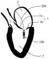
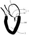
图14-图18是采用图5中的瓣膜夹合装置经左心房顺行接近并对二尖瓣实施缘对缘修复的过程示意图;14-18 are schematic diagrams of the process of using the valve clamping device in FIG. 5 to approach the left atrium antegradely and perform edge-to-edge repair of the mitral valve;
图19是本申请第二实施例的瓣膜夹合装置的结构示意图;19 is a schematic structural diagram of the valve clamping device according to the second embodiment of the present application;
图20是图19中的调节部和支撑部组合后的结构示意图;Figure 20 is a schematic structural diagram of the combination of the adjusting part and the supporting part in Figure 19;
图21是图19中的调节部和固定件组合后的结构示意图;Figure 21 is a schematic structural diagram of the combination of the adjusting part and the fixing part in Figure 19;
图22是本申请第三实施例的瓣膜夹合装置夹持瓣叶时的状态示意图;22 is a schematic diagram of the state when the valve clamping device according to the third embodiment of the present application clamps the valve leaflets;
图23是本申请第四实施例的瓣膜夹合装置的结构示意图;23 is a schematic structural diagram of the valve clamping device according to the fourth embodiment of the present application;
图24是图23中的支撑部、驱动部与夹合部组合后的结构示意图;Figure 24 is a schematic structural diagram of the combination of the support part, the drive part and the clamping part in Figure 23;
图25是图23中的瓣膜夹合装置夹持瓣叶时的状态示意图;Figure 25 is a schematic view of the state of the valve clamping device in Figure 23 when the valve leaflet is clamped;
图26是本申请第五实施例的瓣膜夹合装置的结构示意图;26 is a schematic structural diagram of the valve clamping device according to the fifth embodiment of the present application;
图27是本申请第六实施例的瓣膜夹合装置的结构示意图;27 is a schematic structural diagram of the valve clamping device according to the sixth embodiment of the present application;
图28是图27中的支撑部、驱动部与夹合部组合后的结构示意图;Figure 28 is a schematic structural diagram of the combination of the support part, the drive part and the clamping part in Figure 27;
图29是本申请第七实施例的瓣膜夹合装置的结构示意图;29 is a schematic structural diagram of the valve clamping device according to the seventh embodiment of the present application;
图30是本申请第八实施例的瓣膜夹合装置与输送装置配合的结构示意图;30 is a schematic structural diagram of the cooperation of the valve clamping device and the delivery device according to the eighth embodiment of the present application;
图31是图30所示的瓣膜夹合装置经心尖途径接近二尖瓣的示意图。Figure 31 is a schematic illustration of the valve clamping device shown in Figure 30 approaching the mitral valve via a transapical approach.
具体实施方式Detailed ways
下面将结合附图,对本发明实施例中的技术方案进行清楚、完整地描述,显然,所描述的实施例仅仅是本发明一部分实施例,而不是全部的实施例。基于本发明中的实施例,本领域普通技术人员在没有付出创造性劳动前提下所获得的所有其他实施例,都属于本发明保护的范围。The technical solutions in the embodiments of the present invention will be clearly and completely described below with reference to the accompanying drawings. Obviously, the described embodiments are only a part of the embodiments of the present invention, rather than all the embodiments. Based on the embodiments of the present invention, all other embodiments obtained by those of ordinary skill in the art without creative efforts shall fall within the protection scope of the present invention.
在本发明的描述中,需要说明的是:In the description of the present invention, it should be noted that:
术语“上”、“下”、“内”、“外”等指示的方位或位置关系为基于附图所示的方位或位置关系,仅是为了便于描述本发明和简化描述,而不是指示或暗示所指的装置或元件必须具有特定的方位、以特定的方位构造和操作,因此不能理解为对本发明的限制。此外,术语“第一”、“第二”等仅用于描述目的,而不能理解为指示或暗示相对重要性;The orientation or positional relationship indicated by the terms "upper", "lower", "inner", "outer", etc. is based on the orientation or positional relationship shown in the drawings, and is only for the convenience of describing the present invention and simplifying the description, rather than indicating or It is implied that the device or element referred to must have a particular orientation, be constructed and operate in a particular orientation, and therefore should not be construed as limiting the invention. Furthermore, the terms "first", "second", etc. are used for descriptive purposes only and should not be construed to indicate or imply relative importance;
当元件被称为“固定于”或“设置于”另一个元件时,该元件可以直接地连接在另一个元件上,也可以通过一个或者多个连接元件间接地连接在另一个元件上。当一个元件被称为是“连接于”另一个元件,它可以是直接地连接到另一个元件上,或者通过一个或者多个连接元件连接到另一元件上。When an element is referred to as being "fixed to" or "disposed to" another element, it can be directly connected to the another element or indirectly connected to the another element through one or more connecting elements. When an element is referred to as being "connected to" another element, it can be directly connected to the other element or connected to the other element through one or more connecting elements.
还需要说明的是,在介入医疗器械领域,近端是指距离操作者较近的一端,而远端是指距离操作者较远的一端;将柱体、管体等一类物体的旋转中心轴的方向定义为轴向;周向为围绕柱体、管体等一类物体的轴线的方向(垂直于轴线,同时垂直于截面半径);径向指沿直径或半径的方向。值得注意的是,无论“近端”、“远端”、“一端”、“另一端”、“第一端”、“第二端”、“初始端”、“末端”“两端”“自由端”、“上端”、“下端”等词语中所出现的“端”,并不仅限于端头、端点或端面,也包括自端头、端点、或端面在端头、端点、或端面所属元件上延伸一段轴向距离和/或径向距离的部位。上述定义只是为了表述方便,并不能理解为对本发明的限制。It should also be noted that in the field of interventional medical devices, the proximal end refers to the end that is closer to the operator, and the distal end refers to the end that is farther away from the operator. The direction of the shaft is defined as the axial direction; the circumferential direction is the direction around the axis of a cylinder, tube and other objects (perpendicular to the axis and perpendicular to the radius of the section); the radial direction refers to the direction along the diameter or radius. It is worth noting that regardless of "proximal end", "distal end", "one end", "other end", "first end", "second end", "initial end", "end", "both ends"" The "end" appearing in words such as "free end", "upper end", "lower end" is not limited to the end, end or end face, but also includes from the end, end point, or end face where the end, end point, or end face belongs A location on an element that extends an axial and/or radial distance. The above definitions are only for the convenience of expression, and should not be construed as limiting the present invention.
实施例一Example 1
请参阅图5至图9,本发明第一实施例提供的一种贴合充分的瓣膜夹合装置100包括:Please refer to FIG. 5 to FIG. 9 , a
支撑部110,支撑部110具有一定轴向长度,且包括相对设置的第一端111和第二端115;a
调节部120,调节部120包括相对设置的第一端121和第二端123、以及位于第一端121和第二端123之间的自扩展主体125;the adjusting
以及夹合部130,夹合部130设于调节部120的外侧并可相对于调节部120展开或闭合。And the clamping
该瓣膜夹合装置100的调节部120的第一端121活动套设在支撑部110的外侧,调节部120的第二端123套设在支撑部110的外侧并与支撑部110固定连接。调节部120的第一端121位于支撑部110的第一端111与调节部120的第二端123之间,或者说,调节部120的第一端121相较调节部120的第二端123更靠近支撑部110的第一端111。The
结合图5及图14-图18,该第一实施例的瓣膜夹合装置100在支撑部110的第二端115上设置与输送装置200可拆卸连接(如螺纹连接、卡扣连接等)的连接部(未标示),输送装置200经导管将瓣膜夹合装置100推送至心脏内,则支撑部110的第二端115为其近端,支撑部110的第一端111为其远端,调节部120的第二端123为其近端,调节部120的第一端121为其远端。可以理解的是,在其他实施例中,瓣膜夹合装置可经心尖介入心脏,那么支撑部的第二端为其远端,支撑部的第一端为其近端,调节部的第二端为其远端,调节部的第一端为其近端。5 and FIGS. 14-18 , the
请同时参阅图5-图9,瓣膜夹合装置100主要包括两种状态,一是展开状态,二是闭合状态。展开状态下,调节部120处于不受外力的自然状态,调节部120的自扩展主体125在自然状态下的直径自调节部120的第一端121向调节部120的第二端123逐渐增大,即,调节部120的整体外形近似呈倒锥体形,调节部120的第一端121大致构成倒锥体形的顶点,调节部120的第二端123附近的部位构成倒锥体形的锥底。该第一实施例中,夹合部130的一端转动连接于支撑部110的第一端111,从而夹合部130能够围绕调节部120并以其与支撑部110的第一端111的转动连接部位为中心展开或闭合,调节部120的第一端121与支撑部110的第一端111之间具有轴向间距,从而调节部120受到径向挤压时,调节部120的第一端121能够朝向支撑部110的第一端111做轴向移动,那么在夹合部130以其与支撑部110的第一端111的转动连接部位为中心并围绕调节部120闭合以夹持瓣叶1的过程中,调节部120受到夹合部130的挤压而发生径向回缩、轴向伸长的现象。可以理解的是,在其它实施例中,所述夹合部130的一端也可以转动连接于其它部件上,只要该部件靠近所述支撑部110的第一端111,使得夹合部130设于支撑部110的外侧并可相对于调节部120展开或闭合以夹持住瓣叶即可。Please refer to FIGS. 5-9 at the same time, the
值得注意的是,在闭合状态下,由于调节部120的第二端123固定连接支撑部110,调节部120的第一端121活动套设在支撑部110上,调节部120的第二端123及其附近的部分自扩展主体125的轴向活动受限,自扩展主体125在轴向上会朝向调节部120的第一端121伸长,同时自扩展主体125受夹合部130的挤压会在径向上回缩,伴随着调节部120的第一端121朝向瓣叶1的瓣缘延伸,调节部120的整体外形可与夹合部130张开处的形状互补,并仍呈现出倒锥体形。调节部120的第二端123的附近的部分自扩展主体125位于倒锥体形的锥底,即自扩展主体125向调节部120的第一端121逐渐朝向调节部120的中轴线收拢,调节部120的第二端123附近的部分自扩展主体125与瓣叶1之间能够紧密贴合而不存在径向间隙,相比于现有技术能够增加瓣叶1与调节部120的贴合面积,提升瓣叶1与调节部120的弹性贴合性,使得瓣叶1与调节部120充分贴合。相应地,调节部120的第二端123及其附近的部分自扩展主体125能够为瓣叶1提供较大的径向支撑力,进而提高夹持力以牢靠地夹持住瓣叶1,降低瓣叶1从夹合部130与调节部120之间脱落的风险,提升瓣膜夹合装置100的植入稳定性;同时,调节部120的第二端123附近的部分自扩展主体125与瓣叶1之间的紧密贴合能够封堵自夹合间隙反流的血液,优化反流治疗效果。另外,调节部120可以根据夹合部130夹紧程度的不同而自适应调节自身形状,能够保证在任一夹紧程度下均可以充分贴合瓣叶。It is worth noting that in the closed state, since the
可以理解的是,在闭合状态下,调节部120的第一端121相较现有技术能够朝瓣缘延伸而更加接近瓣缘位置,进一步增加了瓣叶1与调节部120的贴合面积,进一步提升了瓣叶1与调节部120的弹性贴合性。It can be understood that, in the closed state, the
此外,由于调节部120的第一端121活动套设在支撑部110上,调节部120具有较强的轴向变形能力,当该瓣膜夹合装置100被径向压缩到输送鞘中进行体内输送时,较易于被压缩入鞘。In addition, since the
具体的,请参阅图5及图10-图13,支撑部110可以是两端面轴向贯通的圆管体、方柱管体或扁圆管体等。本实施例采用圆管体,如前所述,该圆管体的远端为第一端111,近端为第二端115。支撑部110的第二端115在闭合状态下和展开状态下均可被调节部120的第二端123的附近的部分自扩展主体125包围并遮蔽,从而不会外露出调节部120,防止该第二端115与瓣叶直接接触,避免该第二端115伴随着瓣叶的长期搏动而磨损瓣叶,提高了植入安全性。Specifically, please refer to FIG. 5 and FIGS. 10-13 , the
支撑部110还设有轴向通孔状的穿设通道113,以与驱动部140和输送装置200联动配合。支撑部110的圆管体的管壁上设有至少两个卡位114,用于与输送装置200进行可拆卸连接。例如,输送装置200上设置卡台221,卡台221卡入卡位114后,输送装置200与支撑部110卡合连接,可进行瓣膜夹合装置100的输送,当卡台221脱离卡位114后,输送装置200与瓣膜夹合装置100分离。应当知晓,此处的支撑部110结构仅用作举例,并不是对本申请的限制,本领域的普通技术人员基于本申请的教导,采用的其他支撑部110的结构,均在本申请的保护范围内。The
请参阅图5-图9,调节部120的自扩展主体125为网状结构,优选为由具有形状记忆功能的丝材编织或者管材切割而成的网状结构,例如镍铁合金丝等超弹性材料。在同样的夹合部130闭合程度下,调节部120可适应不同瓣叶之间的间距而发生自适应变形,从而调节瓣膜夹合装置100对瓣叶的牵拉程度。调节部120具有中空容纳腔体(未标示),支撑部110位于第二端115与第一端111之间的部分设于该中空容纳腔体内。Referring to FIGS. 5-9 , the self-expanding
自扩展主体125包括依次连接的第一区段124、第二区段126及第三区段128。第一区段124自调节部120的第二端123朝向支撑部110的第二端115延伸,且该第一区段124相对第二区段126形成一类似于碗状的凹陷区122(如图7及图8a所示),第一区段124围绕在支撑部110的第二端115的外侧,或者说支撑部110的第二端115位于所述凹陷区122内,支撑部110的第二端115在瓣膜夹合装置100的闭合状态下和展开状态下均可被自扩展主体125的第一区段124包围并遮蔽,从而不会外露出调节部120。第二区段126自第一区段124继续径向向外延伸。第三区段128自第二区段126朝向支撑部110的第一端111同时径向向内延伸至调节部12的第一端121截止。该第一实施例中,凹陷区122的末端(将第一区段124靠近调节部120的第二端123的一端定义为凹陷区122的末端)朝向支撑部110的第一端111延伸至调节部120的第二端123。The self-expanding
制作该调节部120时,首先准备一两端开放的编织网管,将编织网管的一端套设在一衬棒上,然后将一成型套套设在该编织网管的一端外,形成调节件120的第二端123;接着向外同时向下拉动编织网管的另一端,使得该编织网管外翻至成型模具上;然后进行热定型处理,形成如图8a至图8b所示的整体外形近似呈倒锥体形的调节部120,且该编织网管的另一端于该编织网管的一端的下方形成调节件120的具有开口的第一端121,取下成型套及成型模具,即得到调节部120。When making the
调节部120与支撑部110组装时,将支撑部110的第二端115与第一端111之间的部分穿设于调节部120的中空容纳腔体内,调节部120的第二端123通过固定件80与支撑部110固定连接,固定件80可以是钢套,调节部120的第二端123穿装于钢套与支撑部110的外表面之间,再通过激光焊接钢套与支撑部110实现调节部120的第二端123与支撑部110的固定连接。可以理解的是,在其他实施例中,也可以不设置固定件80,而直接通过焊接方式将调节部120的第二端123固定连接至支撑部110上。本实施例中,调节部120的第二端123朝向支撑部110的第一端111穿装入固定件80,若以图6中调节部120的第二端123所在的方位为上、调节部120的第一端121所在的方位为下,即调节部120的第二端123从上向下穿装入固定件80。调节部120的第一端121所具有的开口的直径可等于或略大于支撑部110的直径,以活动套设在支撑部110上,从而调节部120的第一端121能够沿支撑部110的轴向顺畅滑动。另,由于调节部120的第二端123与支撑部110固定相连,而调节部120的第一端121活动套设在支撑部110上,整个瓣膜夹合装置100的重心始终位于支撑部110的轴向,因此自中心性较好,不易倾斜。When the adjusting
更为具体的,在瓣膜夹合装置100自展开状态至闭合状态的变化过程中,自扩展主体125的第二区段126的径向尺寸(图6中以D标示)的范围优选为4mm-15mm,更优选5mm-10mm,调节部120的第一端121的径向尺寸的范围为1mm-5mm,更优选1.2mm-3mm,以使得调节部120整体呈现出的倒锥体形被压缩后既能够适应不同瓣叶之间的间距,又能够与瓣叶有尽可能大的贴合面积。More specifically, in the process of changing the
结合图5、图6与图9,在瓣膜夹合装置100的闭合状态下,即瓣叶1被夹持在调节部120与夹合部130之间时,由于调节部120的第二端123固定连接支撑部110,调节部120的第一端121活动套设在支撑部110上,调节部120的第二端123、自扩展主体125的第一区段124及第二区段126的轴向活动受限,调节部120在轴向上会朝向其第一端121伸长,同时自扩展主体125受夹合部130的挤压会在径向上回缩,但第一区段124会抵抗第二区段126的向内变形,第二区段126又会将这种抵抗作用传递至与其相连的第三区段128的相应部分上,伴随着调节部120的第一端121朝向瓣叶1的瓣缘延伸,调节部120的整体外形呈现出与夹合部130张开处的形状互补的倒锥体形,第二区段126位于倒锥体形的锥底,第三区段128自第二区段126向第一端121逐渐朝向调节部120的中轴线收拢,自扩展主体125的第三区段128的整段均能与瓣叶1之间紧密贴合而不存在径向间隙,瓣叶1与调节部120的弹性贴合性得以提升,使得瓣叶1与调节部120能够充分贴合。相应地,调节部120能够为瓣叶1提供较大的径向支撑力,进而提高夹持力以牢靠地夹持住瓣叶1。如图9所示,自扩展主体125的第二区段126不低于夹合部130闭合时的自由端的端面,以使得夹合部130与调节部120之间所夹持的瓣叶1的长度基本与夹合部130等长。5, 6 and 9, in the closed state of the valve clamping device 100, that is, when the valve leaflet 1 is clamped between the adjustment part 120 and the clamping part 130, the second end 123 of the adjustment part 120 The supporting portion 110 is fixedly connected, the first end 121 of the adjusting portion 120 is movably sleeved on the supporting portion 110 , the second end 123 of the adjusting portion 120 , the shafts of the first section 124 and the second section 126 of the self-expanding body 125 When the movement is limited, the adjusting portion 120 will be elongated toward its first end 121 in the axial direction, while the self-expanding body 125 will be radially retracted by the clamping portion 130, but the first section 124 will resist Inward deformation of the second section 126, which in turn transmits this resistance to the corresponding portion of the third section 128 to which it is connected, with the first end 121 of the adjustment portion 120 facing the leaflet The valve edge of 1 extends, the overall shape of the adjustment part 120 presents an inverted cone shape complementary to the shape of the opening of the clamping part 130, the second section 126 is located at the cone bottom of the inverted cone shape, and the third section 128 starts from the third section 128. The
可以理解的是,在其他实施例中,网状结构的调节部120外部和/或内部可覆盖具有生物相容性的薄膜,一方面该薄膜可以作为阻流膜来封堵自夹合间隙反流的血液,提高反流治疗效果,并防止血液进入调节部120中形成血栓,另一方面该薄膜可以使得瓣膜夹合装置100具有更强的生物相容性。该薄膜的材质可以但不限于为PTFE、EPTFE、聚酯、硅树脂等具有生物相容性的聚合物。It can be understood that, in other embodiments, the outside and/or inside of the adjusting
当然,调节部120并不仅限于为网状结构,还可以是其它具有弹性可自扩展的中空结构,例如,可以是致密结构的硅胶体或多孔结构的海绵体,致密结构或多孔结构的调节部的第二端固定套设于支撑部110上,第一端轴向活动套设在支撑部110上,同样可以在第二端与第一端之间设置相似的第一区段、第二区段及第三区段,也可以基于同样的作用原理来使得瓣叶与调节部充分贴合。Of course, the
请参阅图5、及图9-图13,夹合部130包括至少两个钳臂131,一般可以包括至少一组钳臂131,每一组钳臂131包括相对于调节部120对称设置的两个钳臂131。本实施例中的夹合部130包括一组钳臂131,应当知晓,此处仅用作举例,本领域的普通技术人员可以根据需要选择合适的钳臂131数量,例如两组或更多组钳臂。可以理解的是,还可以根据需要在每组中设置三个或更多个钳臂131,例如,可以通过三个可相对开合的钳臂131来同时夹合三尖瓣的三片瓣叶,从而治疗三尖瓣反流;或者通过一对钳臂131来夹合三尖瓣的其中两片瓣叶,也可达到减轻或治疗三尖瓣反流的目的。Please refer to FIG. 5 , and FIGS. 9 to 13 , the clamping
本实施例中,瓣膜夹合装置100还包括驱动部140,驱动部140与夹合部130连接,以驱动夹合部130相对于调节部120展开或闭合。具体地,驱动部140分别与每个钳臂131连接,例如驱动部140分别与一组钳臂131中的两个钳臂131连接,以驱动每个钳臂131围绕调节部120转动,从而使得钳臂131靠近或远离调节部120。输送状态下,驱动部140驱动钳臂131围绕调节部120闭合,从而减少瓣膜夹合装置100的外径,利于输送;瓣膜夹合装置100在心脏内展开后,驱动部140驱动钳臂131将瓣叶夹持在钳臂131与调节部120之间,实现瓣叶夹持。In this embodiment, the
在本实施例的一优选实施方式中,瓣膜夹合装置100还包括抓持部,一般可以包括至少一组抓持臂151,每一组抓持臂151包括相对于调节部120对称设置的两个抓持臂151。抓持部(例如抓持臂151)设于夹合部130(例如钳臂131)与调节部120之间并可相对调节部120展开或闭合,抓持部至少部分容置于夹合部130的内表面。当然,还可以根据需要在每组中设置三个或更多个抓持臂151,从而与钳臂131配合实现瓣叶捕捉功能。In a preferred implementation of this embodiment, the
输送状态下,抓持部至少部分容纳在夹合部130的内表面中,即抓持臂151至少部分容纳在钳臂131的内表面中,从而减少了瓣膜夹合装置100的外径,利于输送。在钳臂131与抓持臂151配合捕捉瓣叶后,抓持臂151将瓣叶压入钳臂131的内表面中,可以增加钳臂131与瓣叶的接触面积、增加对瓣叶的夹持力。In the delivery state, the grasping portion is at least partially accommodated in the inner surface of the clamping
瓣膜夹合装置100还包括与支撑部110固定连接的基座160,每一钳臂131均转动连接于基座160上。具体地,基座160的近端与支撑部110的第一端111固定连接,应当说明,此处为了阐述方便将此部分定义为术语“基座”,实现该基座160功能的结构也可以是支撑部110的第一端111自身,因此定义术语“基座”不应形成对本申请范围的限制。每一组中的每个钳臂131在基座160上通过枢轴132转动连接在一起,调节部120的第一端121与基座160在轴向上间隔开,在驱动部140的驱动下,每个钳臂131彼此配合可以一起围绕调节部120展开和闭合。The
本实施例中,驱动部140包括:驱动轴141、连接座142以及两个连杆143。其中,每个连杆143的一端与夹合部130转动连接,另一端与连接座142转动连接;驱动轴141的一端与连接座142固定连接,另一端活动地穿装在基座160中。具体地,每一连杆143的一端与一钳臂131转动连接,另一端通过枢轴144转动连接于连接座142,即,每一钳臂131通过相应一侧的连杆143转动连接于驱动轴141的连接座142。驱动轴141活动地穿过基座160,当驱动轴141相对于基座160沿轴向滑动时,带动连杆143转动并带动钳臂131以其与基座160的转动连接部位为中心展开或闭合。In this embodiment, the driving
具体的,驱动部140包括至少一组连杆143,连杆143的设置与钳臂131的设置一一对应,例如图10中采用两个钳臂131,则相对应地设置两个配合工作的连杆143。连杆143的一端通过枢轴144如销钉等方式转动连接于连接座142上,另一端通过枢轴如销钉等方式转动连接于相应的钳臂131,每个钳臂131通过枢轴132如销钉等方式转动连接在基座160上。当驱动轴141沿轴向相对于基座160朝支撑部110的第一端111移动,带动连杆143运动,在连杆143的拉动下,钳臂131围绕枢轴132转动而相对于基座160张开。当驱动轴141沿轴向相对于基座160朝支撑部110的第二端115移动,连杆143推动钳臂131围绕枢轴132转动而相对于基座160闭合。连接座142的形状可为半球体、球冠或弹头形等任一结构,以使瓣膜夹合装置100更容易在体内进行推送。驱动轴141与连接座142可以是一体结构,也可以是非一体结构。为保证植入后的安全性,驱动轴141及连接座142由聚酯、硅树脂、不锈钢、钴合金、钴铬合金或钛合金等生物相容性材料制成,优选为硬度较高的不锈钢或钴铬合金。Specifically, the driving
优选地,参见图10所示,瓣膜夹合装置100还包括设于基座160中的锁定部170,锁定部170限制驱动轴141与基座160的相对运动。在输送状态时,锁定部170限制驱动轴141与基座160的相对运动,从而保证夹合部130相对于调节部120和支撑部110始终保持闭合状态,避免夹合部130的意外展开;在到达二尖瓣附近后,解锁锁定部170对驱动轴141的限制,即可通过驱动部140驱动夹合部130相对于调节部120和支撑部110展开并承托瓣叶;夹持瓣叶后,锁定部170再次限制驱动轴141与基座160的相对运动,从而保持对瓣叶1的夹紧状态。可采用现有的任意适合结构的锁定部,此处不再赘述。Preferably, as shown in FIG. 10 , the
结合图5与图9,进一步地,每一钳臂131的末端(将钳臂131远离其转动连接部位的一端或者说自由端定义为钳臂131的末端)还设有翻边段137,从图9的主视视角看,翻边段137呈朝向钳臂131的末端的外侧翻转的弧面,该弧面的半径优选1mm-2mm。当钳臂131相对调节部120闭合以在二者之间夹持瓣叶1时,瓣叶1与弧面的翻边段137形成贴合,增大钳臂131末端对瓣叶1的承托面积,能够避免瓣叶1在钳臂131末端局部受力集中,有效减轻钳臂131末端边缘随着心脏跳动与瓣叶1之间反复摩擦对瓣叶的损伤。钳臂131贴靠至调节部120后,调节部120的自扩展主体125在轴向上突出于翻边段137,或者说自扩展主体125的第二区段126高于翻边段137,以保证钳臂131与自扩展主体125的第三区段128之间所夹持的瓣叶1的长度不小于钳臂131的长度。5 and 9, further, the end of each clamp arm 131 (the end of the
参阅图13-图17,本发明还提供一种瓣膜夹合系统,包括上述瓣膜夹合装置100、以及输送装置200,其中,输送装置200包括:具有一定轴向长度的推送鞘管210及活动地穿装在推送鞘管210中的芯轴(图中未示出),推送鞘管210与支撑部110之间可拆卸连接,芯轴与驱动部140可拆卸连接,用于驱动夹合部130的展开和闭合。本实施例中,驱动轴141的近端设置外螺纹,芯轴与驱动轴141之间通过螺纹连接,从而可在患者体外通过芯轴来控制驱动轴141的轴向运动。应当知晓,此处列出的仅是输送装置的部分结构,其他部分可采用现有的任一适合的结构,此处不再赘述。13-17, the present invention also provides a valve clamping system, including the above-mentioned
具体地,支撑部110的近端外壁对称开设有连通于支撑部110的管腔的至少一卡位114,推送鞘管210远端设有一连接件220,连接件220包括两个分支,每个分支的末端为凸起的卡台221。在自然状态,两个分支均指向连接件220的中心轴处。组装时,将连接件220插入支撑部110中,再将输送装置200的芯轴插入推送鞘管210中,直至芯轴插入连接件220中,将连接件220的两个分支向外顶起,分支末端的卡台221卡入支撑部110的两个卡位114中,从而将支撑部110与连接件220连接,即,将瓣膜夹合装置100和输送装置200相连。当将芯轴自连接件220及推送鞘管210中撤出,两个分支恢复向内的自然状态,卡台221从支撑部110的卡位114中脱离,使得瓣膜夹合装置100与输送装置200之间解除连接。连接件220可由镍钛等具有一定硬度及弹性的材料制成。推送鞘管210可采用多层复合管体。芯轴可为不锈钢材料或镍钛合金材料制成。Specifically, the outer wall of the proximal end of the
结合图11与图13,支撑部110的内部设有通孔作为驱动轴141的穿设通道113,驱动轴141沿轴向滑动地穿设于支撑部110的穿设通道113内并与连接座142固定连接。在夹合部130和抓持部150配合并捕捉到瓣叶后,通过芯轴带动驱动轴141沿轴向移动,以带动钳臂131相对于支撑部110完全闭合,使瓣膜夹合装置100处于闭合状态,坠于瓣膜下方。之后可以解脱芯轴与驱动轴141之间的连接,芯轴自连接件220之间后撤,卡台221自支撑部110的卡位114中分离,从而实现瓣膜夹合装置100和输送装置200的解脱。11 and FIG. 13 , a through hole is provided inside the
参阅图14-图18,以下以经导管途径经房间隔-左心房顺行接近并修复二尖瓣为例,阐述本申请的瓣膜夹合装置100的使用过程:Referring to FIGS. 14-18 , the following uses the transcatheter approach to approach and repair the mitral valve through the transatrial septum-left atrium antegrade as an example to illustrate the use process of the
第一步:如图14所示,通过可调弯鞘管等导引装置(图未示出)将驱动轴141及与其相连的瓣膜夹合装置100从左心房2推进,经过二尖瓣1到达左心室3;Step 1: As shown in FIG. 14, the
第二步:调整瓣膜夹合装置100接近二尖瓣1的前叶1a和后叶1b;The second step: adjusting the
第三步:如图15所示,解锁基座160中的锁定部170,向远端推动芯轴及驱动轴141,驱动钳臂131相对于支撑部110张开,调整钳臂131方向,此时可通过X射线设备观察钳臂131与二尖瓣1的前叶1a和后叶1b的相对位置,使得钳臂131垂直于二尖瓣1的对合线;Step 3: As shown in FIG. 15 , unlock the locking
第四步:如图16所示,向近端回撤整个瓣膜夹合装置100,使钳臂131在左心室3侧托住瓣叶1,释放两侧的抓持臂151,每侧的抓持臂151在心房侧压住瓣叶1并与该侧的钳臂131配合捕捉住瓣叶1;Step 4: As shown in FIG. 16 , withdraw the entire
第五步:如图17所示,当二尖瓣1的前叶1a和后叶1b分别被捕捉在一对钳臂131和抓持臂151之间,向近端拉动芯轴及驱动轴141,从而驱动钳臂131闭合;Step 5: As shown in FIG. 17, when the
第六步:解脱芯轴与驱动轴141之间的螺纹连接,并后撤芯轴,连接件220的两个分支恢复向中心轴靠拢的状态,卡台221自支撑部110的卡位114中分离,瓣膜夹合装置100与输送装置200之间的连接解除,之后将输送装置200撤出体外,得到如图18所示的植入状态,此时瓣膜夹合装置100将二尖瓣1的前叶1a和后叶1b拉向彼此,得到双孔化的二尖瓣,完成二尖瓣的缘对缘修复。Step 6: Release the threaded connection between the mandrel and the
瓣膜夹合装置100植入后,具有弹性的调节部120填充于被夹持的二尖瓣1的前叶1a和后叶1b之间,且为瓣叶1提供径向支撑力,调节部120对于搏动的瓣叶1具有缓冲作用,从而实现瓣膜夹合装置100对瓣叶1的牵拉程度可调节,以避免损伤瓣叶1。After the
实施例二
请参阅图19至图21,本发明第二实施例提供的瓣膜夹合装置100’与上述第一实施例的瓣膜夹合装置100相比较,支撑部110、夹合部130、驱动部140、抓持部151等的结构保持不变,此处不再赘述,但调节部120’的结构发生了变化。Referring to FIGS. 19 to 21 , the
具体的,在该第二实施例中,调节部120’相比第一实施例中的调节部120对自扩展主体增设了弯折区段129,弯折区段129连接于调节部120’的第二端123与自扩展主体的第一区段124之间,优选的,弯折区段129的截面形状呈朝向调节部120’的第一端121凹陷的弧形。第一区段124与弯折区段129相对第二区段126仍形成一凹陷区122’,凹陷区122’的末端(将弯折区段129靠近调节部120’的第二端123的一端定义为凹陷区122’的末端)朝向支撑部110的第二端115延伸至调节部120’的第二端123。Specifically, in the second embodiment, compared with the adjusting
制作该调节部120’时,首先准备一两端开放的编织网管,将编织网管套设在一衬棒上,然后将一成型套套设在该编织网管的上端外,形成调节件120’的第二端123;接着向上(以图20中调节部120’的第二端123所在的方位为上、第一端121所在的方位为下,)推动编织网管的下端,并借助成型模具对该编织网管进行热定型处理,形成如图20与图21所示的整体外形仍近似呈倒锥体形的调节部120’,且该编织网管的下端于该编织网管的上端的下方形成调节件120’的具有开口的第一端121,取下成型套及成型模具,即得到调节部120’。When making the adjustment part 120', first prepare a braided mesh tube with open ends, sleeve the braided mesh tube on a lining rod, and then sleeve a forming sleeve over the upper end of the braided mesh tube to form the first part of the adjustment part 120'. Two ends 123; then upward (with the orientation of the
调节部120’与支撑部110组装时,将支撑部110的第二端115与第一端111之间的部分穿设于调节部120的中空容纳腔体内,调节部120’的第二端123通过固定件80与支撑部110固定连接,固定件80可以是钢套,调节部120的第二端123穿装于钢套与支撑部110的外表面之间,再通过激光焊接钢套与支撑部110实现调节部120’的第二端123与支撑部110的固定连接。本实施例中,调节部120’的第二端123朝向支撑部110的第二端115穿装入固定件80,即调节部120’的第二端123从下向上穿装入固定件80。When the adjusting part 120' is assembled with the supporting
在瓣膜夹合装置100’的闭合状态下,弯折区段129抵抗第一区段124的向内变形,这种抵抗作用叠加传递至与第二区段126相连的第三区段128的相应部分上,进一步提升瓣叶与调节部120的弹性贴合性,使得瓣叶与调节部120能够充分贴合。相应地,调节部120能够为瓣叶提供更大的径向支撑力,进而进一步提高夹持力以牢靠地夹持住瓣叶。In the closed state of the
实施例三
如图22所示,本发明第三实施例提供的瓣膜夹合装置与上述第一实施例的瓣膜夹合装置相比较,支撑部、夹合部、驱动部、抓持部等的结构保持不变,此处不再赘述,但调节部的自扩展主体125’的结构发生了变化。As shown in FIG. 22 , the valve clamping device provided by the third embodiment of the present invention, compared with the valve clamping device of the first embodiment, the structures of the supporting part, the clamping part, the driving part, the grasping part, etc. remain unchanged. The structure of the self-expanding
该实施例三中的自扩展主体125’除了包括第一区段124、第二区段126与第三区段128之外,还包括适配段127。适配段127连接于第二区段126与第三区段128之间,且相较于第三区段128径向向外延伸(以朝向支撑部110的中轴线为径向向内,以背离支撑部110的中轴线为径向向外)。该适配段127对应钳臂末端的翻边段137设置,其朝向翻边段137的一侧的形状与翻边段137所呈现的弧面互补。In addition to the
当钳臂相对调节部120闭合以在二者之间夹持瓣叶时,适配段127在轴向上突出于翻边段137,或者说适配段127高于翻边段137,适配段127与翻边段137之间也夹持部分瓣叶,一方面瓣叶与翻边段137的弧面形成贴合,增大钳臂末端对瓣叶的承托面积,能够避免瓣叶在钳臂末端局部受力集中,有效减轻钳臂末端边缘随着心脏跳动与瓣叶之间反复摩擦对瓣叶的损伤;另一方面,瓣叶亦与弧形的适配段127形成贴合,进一步增加瓣叶与调节部的贴合面积,提升瓣叶与调节部的弹性贴合性,使得瓣叶与调节部贴合地更为充分,相应地,调节部能够为瓣叶提供更充足的径向支撑力,进而进一步提高夹持力以牢靠地夹持住瓣叶。When the forceps arm is closed relative to the adjusting
实施例四
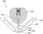
请参阅图23至图25,本发明第四实施例提供的瓣膜夹合装置400与上述第一实施例的瓣膜夹合装置100相比较,调节部120的结构保持不变,此处不再赘述,但支撑部410、夹合部430、驱动部440的结构有所变化。Referring to FIGS. 23 to 25 , the
具体的,在该第四实施例中,夹合部430包括至少两个钳臂,一般可以包括至少一组钳臂,每一组钳臂包括相对于调节部120对称设置的两个钳臂,本实施例中的夹合部40包括一组钳臂。每一钳臂上设有至少一个锚定件431,当钳臂相对于调节部120闭合时,锚定件431能够抵顶瓣叶使其嵌置于网状结构的调节部120的网格中,以在调节部120与钳臂夹持瓣叶的基础上,通过锚定件431保持瓣叶组织。Specifically, in the fourth embodiment, the clamping
驱动部440包括驱动轴410、自动闭合单元445以及至少两个连杆443。其中,每个所述连杆443的一端与相应的一钳臂转动连接,另一端通过销轴直接与驱动轴441转动连接;驱动轴441活动穿装于支撑部410中;自动闭合单元445连接两钳臂,用于使得夹合部430在自然状态下贴靠调节部120。The driving
基座416与支撑部410的第一端411为一体结构,两钳臂转动连接于基座416。支撑部410上开设有供销轴穿过的轴向槽419。当驱动轴441带动销轴在轴向槽419内向支撑部410的第一端411移动时,带动连杆443克服自动闭合单元445的阻挠而使得两钳臂相对打开。The
本实施例中,所述自动闭合单元445为U形弹片,U形弹片的两端分别连接一钳臂,当驱动轴441不对销轴施加推力时,U形弹片利用自身复位带动两钳臂趋向闭合而贴靠调节部120。可以理解的是,在其他实施例中,自动闭合单元445还可以为V形弹片或扭簧等弹性件。In this embodiment, the
实施例五Embodiment 5
请参阅图26,本发明第五实施例提供的瓣膜夹合装置400’与上述第四实施例的瓣膜夹合装置400相比较,将第四实施例中的调节部120替换为第二实施例中的调节部120’,其他结构保持不变,此处不再赘述。Referring to FIG. 26 , the
实施例六Embodiment 6
请参阅图27与图28,本发明第六实施例提供的瓣膜夹合装置500与上述第一实施例的瓣膜夹合装置100相比较,调节部120的结构保持不变,此处不再赘述,但夹合部530、驱动部540等的结构有所变化。Please refer to FIG. 27 and FIG. 28 . Compared with the
该实施例中,基座516与支撑部510的第一端511为一体结构,夹合部530的钳臂的一端连接于基座516。驱动部540包括驱动轴541以及至少两个弹性驱动臂545,弹性驱动臂545的一端固定连接驱动轴541的一端,弹性驱动臂545的另一端连接钳臂的另一端,驱动轴545的另一端活动穿装于支撑部510中;弹性驱动臂545用于使得夹合部530在自然状态下贴靠调节部120;抓持臂551的一端连接于夹合部530的钳臂上,且在瓣膜夹合装置500的展开状态下,抓持臂551受输送装置内拉线(图未示)的控制而相对钳臂张开,以允许瓣叶进入抓持臂551与钳臂之间。In this embodiment, the
本实施例中,两钳臂及两弹性驱动臂545为一体结构,即两钳臂自身也是具有弹性的。当驱动轴541朝向支撑部510的第一端511移动时,克服两弹性驱动臂545的阻挠而使得两钳臂相对打开;当驱动轴541不对弹性驱动臂545施加推力时,两弹性驱动臂545利用自身复位而带动两钳臂趋向闭合而贴靠调节部120。值得注意的是,当驱动轴541朝向支撑部510的第一端511持续推动时,可使得钳臂与驱动臂545的连接处逐渐朝向驱动轴541靠近,直至钳臂与驱动臂545基本处于一条直线上,再利用拉线控制抓持臂551贴合调节部120,此种状态下,更易于将扁平化的整个瓣膜夹合装置500收入鞘管内。In this embodiment, the two clamp arms and the two elastic driving
此外,该实施例的瓣膜夹合装置500能够实现对瓣叶夹合状态的动态平衡:当瓣叶对该瓣膜夹合装置500施加较大的牵拉力时,具有弹性的驱动臂545及钳臂能够在一定范围内调节夹合角度又不会与瓣叶脱离,防止瓣叶受到过大的牵拉力而损伤。In addition, the
实施例七Embodiment 7
请参阅图29,本发明第七实施例提供的瓣膜夹合装置500’与上述第六实施例的瓣膜夹合装置500相比较,将第六实施例中的调节部120替换为第二实施例中的调节部120’,其他结构保持不变,此处不再赘述。Referring to FIG. 29 , the
实施例八Embodiment 8
请参阅图30与图31,本发明第八实施例提供的瓣膜夹合装置600与上述第一实施例的瓣膜夹合装置100相比较,仅支撑部610的结构发生变化,其它结构保持不变,此处不再赘述。Please refer to FIG. 30 and FIG. 31 . Compared with the
该实施例中,支撑部610与输送装置200’的连接部位不再像第一实施例那样设置于第二端,而是在支撑部610第一端的基座660上设置连接部670,该连接部670与输送装置200’的推送鞘管可拆卸连接。具体的,该连接部670与输送装置200’的推送鞘管上分别设置形状互补的拼接结构,推送鞘管外活动套设一外鞘管70,当外鞘管70包绕所述形状互补的拼接结构时,支撑部610与输送装置200’保持连接,当外鞘管70后撤并暴露出所述形状互补的拼接结构时,支撑部610与输送装置200’可解除连接。In this embodiment, the connecting portion between the
如图31所示,该实施例的输送装置200’可通过经心尖的方式将该瓣膜夹合装置600推送至心脏内对二尖瓣实施缘对缘修复。需要注意的是,在两钳臂完成闭合之前,外鞘管70应保持包绕所述形状互补的拼接结构;在两钳臂完成闭合之后,先解脱芯轴与驱动轴之间的螺纹连接,并后撤芯轴,然后后撤外鞘管70使得所述拼接结构暴露,便可解除瓣膜夹合装置600与输送装置200’之间的连接。As shown in FIG. 31 , the delivery device 200' of this embodiment can push the
可以理解的是,本发明提供的瓣膜夹合系统包括上述的任一瓣膜夹合装置以及能够将该瓣膜夹合装置从体外输送至二尖瓣附近并夹合瓣叶的输送装置。It can be understood that the valve clamping system provided by the present invention includes any of the above-mentioned valve clamping devices and a delivery device capable of delivering the valve clamping device to the vicinity of the mitral valve from outside the body and clamping the valve leaflets.
可以理解的是,本发明提供的瓣膜夹合装置及瓣膜夹合系统也可以对三尖瓣实施缘对缘修复,只要选择相应的介入路径(如股静脉-下腔静脉-右心房-右心室)以及根据需要修复的瓣叶数量植入适合数量的瓣膜夹合装置即可(如植入三个瓣膜夹合装置分别夹持三尖瓣的前叶与后叶、后叶与隔叶、隔叶与前叶)。It can be understood that the valve clamping device and valve clamping system provided by the present invention can also perform edge-to-edge repair on the tricuspid valve, as long as the corresponding interventional route (such as femoral vein-inferior vena cava-right atrium-right ventricle) is selected. ) and the appropriate number of valve clamping devices can be implanted according to the number of valve leaflets to be repaired (for example, three valve clamping devices are implanted to clamp the anterior leaflet and posterior leaflet, posterior leaflet and septal leaflet, and septal leaflet of tricuspid valve respectively. leaves and anterior leaves).
以上所述仅是本发明的具体实施例,使本领域技术人员能够理解或实现本发明。对这些实施例的多种修改对本领域的技术人员来说将是显而易见的,本文中所定义的一般原理可以在不脱离本发明的精神或范围的情况下,在其它实施例中实现。因此,本发明将不会被限制于本文所示的这些实施例,而是要符合与本文所申请的原理和新颖特点相一致的最宽的范围。The above descriptions are only specific embodiments of the present invention, so that those skilled in the art can understand or implement the present invention. Various modifications to these embodiments will be readily apparent to those skilled in the art, and the generic principles defined herein may be implemented in other embodiments without departing from the spirit or scope of the invention. Thus, the present invention is not intended to be limited to the embodiments shown herein, but is to be accorded the widest scope consistent with the principles and novel features claimed herein.
Claims (19)
Translated fromChinesePriority Applications (6)
| Application Number | Priority Date | Filing Date | Title |
|---|---|---|---|
| CN202411812051.4ACN119632731B (en) | 2021-01-15 | 2021-01-15 | Fully fitted valve clipping devices and valve clipping systems |
| CN202110057563.4ACN114762635B (en) | 2021-01-15 | 2021-01-15 | Fully fitted valve clipping device and valve clipping system |
| BR112022018791ABR112022018791A2 (en) | 2020-03-18 | 2021-03-18 | VALVE FIXING DEVICE AND VALVE FIXING SYSTEM |
| EP21770911.2AEP4122426A4 (en) | 2020-03-18 | 2021-03-18 | Valve clamping device and valve clamping system |
| US17/906,641US20230157819A1 (en) | 2020-03-18 | 2021-03-18 | Valve clamping device and valve clamping system |
| PCT/CN2021/081606WO2021185324A1 (en) | 2020-03-18 | 2021-03-18 | Valve clamping device and valve clamping system |
Applications Claiming Priority (1)
| Application Number | Priority Date | Filing Date | Title |
|---|---|---|---|
| CN202110057563.4ACN114762635B (en) | 2021-01-15 | 2021-01-15 | Fully fitted valve clipping device and valve clipping system |
Related Child Applications (1)
| Application Number | Title | Priority Date | Filing Date |
|---|---|---|---|
| CN202411812051.4ADivisionCN119632731B (en) | 2021-01-15 | 2021-01-15 | Fully fitted valve clipping devices and valve clipping systems |
Publications (2)
| Publication Number | Publication Date |
|---|---|
| CN114762635Atrue CN114762635A (en) | 2022-07-19 |
| CN114762635B CN114762635B (en) | 2025-05-30 |
Family
ID=82364745
Family Applications (2)
| Application Number | Title | Priority Date | Filing Date |
|---|---|---|---|
| CN202110057563.4AActiveCN114762635B (en) | 2020-03-18 | 2021-01-15 | Fully fitted valve clipping device and valve clipping system |
| CN202411812051.4AActiveCN119632731B (en) | 2021-01-15 | 2021-01-15 | Fully fitted valve clipping devices and valve clipping systems |
Family Applications After (1)
| Application Number | Title | Priority Date | Filing Date |
|---|---|---|---|
| CN202411812051.4AActiveCN119632731B (en) | 2021-01-15 | 2021-01-15 | Fully fitted valve clipping devices and valve clipping systems |
Country Status (1)
| Country | Link |
|---|---|
| CN (2) | CN114762635B (en) |
Cited By (3)
| Publication number | Priority date | Publication date | Assignee | Title |
|---|---|---|---|---|
| CN116269933A (en)* | 2022-12-30 | 2023-06-23 | 杭州端佑医疗科技有限公司 | Valve repair device and system |
| CN117982268A (en)* | 2022-11-03 | 2024-05-07 | 杭州德晋医疗科技有限公司 | Valve clamping device and valve clamping system with stable fitting |
| CN114762635B (en)* | 2021-01-15 | 2025-05-30 | 杭州德晋医疗科技有限公司 | Fully fitted valve clipping device and valve clipping system |
Citations (26)
| Publication number | Priority date | Publication date | Assignee | Title |
|---|---|---|---|---|
| CN103826548A (en)* | 2011-09-13 | 2014-05-28 | 艾博特心脏血管系统公司 | Independent gripper |
| US20160089234A1 (en)* | 2013-05-20 | 2016-03-31 | Twelve, Inc. | Implantable heart valve devices, mitral valve repair devices and associated systems and methods |
| US20160120643A1 (en)* | 2014-11-05 | 2016-05-05 | Tara Kupumbati | Transcatheter cardiac valve prosthetic |
| CN106175986A (en)* | 2016-07-26 | 2016-12-07 | 复旦大学附属中山医院 | A valve clamp |
| CN106491245A (en)* | 2015-09-06 | 2017-03-15 | 先健科技(深圳)有限公司 | Valve clamping device |
| US20170172737A1 (en)* | 2015-12-22 | 2017-06-22 | Nvt Ag | Prosthetic mitral valve coaptation enhancement device |
| WO2018077145A1 (en)* | 2016-10-24 | 2018-05-03 | 宁波健世生物科技有限公司 | Adaptive heart valve prosthesis |
| WO2018077143A1 (en)* | 2016-10-24 | 2018-05-03 | 宁波健世生物科技有限公司 | Heart valve prosthesis |
| CN109199468A (en)* | 2018-06-08 | 2019-01-15 | 杭州德晋医疗科技有限公司 | Adjustable Heart valve repair system |
| CN109350309A (en)* | 2018-12-03 | 2019-02-19 | 宁波健世生物科技有限公司 | A kind of stent valve prosthese and its transportation system |
| CN109414321A (en)* | 2017-02-07 | 2019-03-01 | 上海甲悦医疗器械有限公司 | The device for treating valvular regurgitation |
| US20190247191A1 (en)* | 2018-02-12 | 2019-08-15 | 4C Medical Technologies, Inc. | Expandable frames and paravalvular leak mitigation systems for implantable prosthetic heart valve devices |
| WO2019184649A1 (en)* | 2018-03-28 | 2019-10-03 | 杭州德晋医疗科技有限公司 | Heart valve repair system and suture locking device thereof |
| CN209464132U (en)* | 2017-10-19 | 2019-10-08 | 上海捍宇医疗科技有限公司 | A kind of the valve clamping machine and its system of adjustable clamping position |
| CN209548144U (en)* | 2018-05-17 | 2019-10-29 | 杭州德晋医疗科技有限公司 | Valve clamping machine and valve clamping system |
| CN110495972A (en)* | 2018-05-17 | 2019-11-26 | 杭州德晋医疗科技有限公司 | Valve Clamping Device and Valve Clamping System |
| CN110536656A (en)* | 2017-04-18 | 2019-12-03 | 爱德华兹生命科学公司 | Heart valve sealing device and its delivery apparatus |
| CN211243911U (en)* | 2019-08-12 | 2020-08-14 | 杭州德晋医疗科技有限公司 | Recoverable valve clamping device and valve clamping device recovery system |
| CN211325891U (en)* | 2019-08-13 | 2020-08-25 | 杭州德晋医疗科技有限公司 | Adjustable valve clamping device and valve clamping system |
| CN111671547A (en)* | 2019-07-31 | 2020-09-18 | 杭州德晋医疗科技有限公司 | Valve clamp with cover and valve clamp system |
| CN111772874A (en)* | 2019-08-06 | 2020-10-16 | 上海捍宇医疗科技有限公司 | A valve clamp and its clamping system |
| CN111789699A (en)* | 2019-11-19 | 2020-10-20 | 杭州德晋医疗科技有限公司 | Independently controllable valve clamping system |
| CN211723548U (en)* | 2019-10-30 | 2020-10-23 | 杭州德晋医疗科技有限公司 | Adjustable valve clamping system |
| CN111904660A (en)* | 2020-03-18 | 2020-11-10 | 杭州德晋医疗科技有限公司 | Valve clamping device and valve clamping system |
| CN111938870A (en)* | 2020-08-21 | 2020-11-17 | 杭州德晋医疗科技有限公司 | Valve clamping device with locking mechanism and valve repair system |
| CN112206017A (en)* | 2019-07-12 | 2021-01-12 | 杭州德晋医疗科技有限公司 | Easy-to-grip valve clamp and valve clamp system |
Family Cites Families (6)
| Publication number | Priority date | Publication date | Assignee | Title |
|---|---|---|---|---|
| WO2005048883A1 (en)* | 2003-11-13 | 2005-06-02 | Fidel Realyvasquez | Methods and apparatus for valve repair |
| US8496671B1 (en)* | 2010-06-16 | 2013-07-30 | Cardica, Inc. | Mitral valve treatment |
| US10524912B2 (en)* | 2015-04-02 | 2020-01-07 | Abbott Cardiovascular Systems, Inc. | Tissue fixation devices and methods |
| EP3294219B1 (en)* | 2015-05-14 | 2020-05-13 | Edwards Lifesciences Corporation | Heart valve sealing devices and delivery devices therefor |
| CN114762635B (en)* | 2021-01-15 | 2025-05-30 | 杭州德晋医疗科技有限公司 | Fully fitted valve clipping device and valve clipping system |
| CN111449805B (en)* | 2020-04-02 | 2025-08-15 | 科凯(南通)生命科学有限公司 | Valve repair clamp |
- 2021
- 2021-01-15CNCN202110057563.4Apatent/CN114762635B/enactiveActive
- 2021-01-15CNCN202411812051.4Apatent/CN119632731B/enactiveActive
Patent Citations (26)
| Publication number | Priority date | Publication date | Assignee | Title |
|---|---|---|---|---|
| CN103826548A (en)* | 2011-09-13 | 2014-05-28 | 艾博特心脏血管系统公司 | Independent gripper |
| US20160089234A1 (en)* | 2013-05-20 | 2016-03-31 | Twelve, Inc. | Implantable heart valve devices, mitral valve repair devices and associated systems and methods |
| US20160120643A1 (en)* | 2014-11-05 | 2016-05-05 | Tara Kupumbati | Transcatheter cardiac valve prosthetic |
| CN106491245A (en)* | 2015-09-06 | 2017-03-15 | 先健科技(深圳)有限公司 | Valve clamping device |
| US20170172737A1 (en)* | 2015-12-22 | 2017-06-22 | Nvt Ag | Prosthetic mitral valve coaptation enhancement device |
| CN106175986A (en)* | 2016-07-26 | 2016-12-07 | 复旦大学附属中山医院 | A valve clamp |
| WO2018077145A1 (en)* | 2016-10-24 | 2018-05-03 | 宁波健世生物科技有限公司 | Adaptive heart valve prosthesis |
| WO2018077143A1 (en)* | 2016-10-24 | 2018-05-03 | 宁波健世生物科技有限公司 | Heart valve prosthesis |
| CN109414321A (en)* | 2017-02-07 | 2019-03-01 | 上海甲悦医疗器械有限公司 | The device for treating valvular regurgitation |
| CN110536656A (en)* | 2017-04-18 | 2019-12-03 | 爱德华兹生命科学公司 | Heart valve sealing device and its delivery apparatus |
| CN209464132U (en)* | 2017-10-19 | 2019-10-08 | 上海捍宇医疗科技有限公司 | A kind of the valve clamping machine and its system of adjustable clamping position |
| US20190247191A1 (en)* | 2018-02-12 | 2019-08-15 | 4C Medical Technologies, Inc. | Expandable frames and paravalvular leak mitigation systems for implantable prosthetic heart valve devices |
| WO2019184649A1 (en)* | 2018-03-28 | 2019-10-03 | 杭州德晋医疗科技有限公司 | Heart valve repair system and suture locking device thereof |
| CN209548144U (en)* | 2018-05-17 | 2019-10-29 | 杭州德晋医疗科技有限公司 | Valve clamping machine and valve clamping system |
| CN110495972A (en)* | 2018-05-17 | 2019-11-26 | 杭州德晋医疗科技有限公司 | Valve Clamping Device and Valve Clamping System |
| CN109199468A (en)* | 2018-06-08 | 2019-01-15 | 杭州德晋医疗科技有限公司 | Adjustable Heart valve repair system |
| CN109350309A (en)* | 2018-12-03 | 2019-02-19 | 宁波健世生物科技有限公司 | A kind of stent valve prosthese and its transportation system |
| CN112206017A (en)* | 2019-07-12 | 2021-01-12 | 杭州德晋医疗科技有限公司 | Easy-to-grip valve clamp and valve clamp system |
| CN111671547A (en)* | 2019-07-31 | 2020-09-18 | 杭州德晋医疗科技有限公司 | Valve clamp with cover and valve clamp system |
| CN111772874A (en)* | 2019-08-06 | 2020-10-16 | 上海捍宇医疗科技有限公司 | A valve clamp and its clamping system |
| CN211243911U (en)* | 2019-08-12 | 2020-08-14 | 杭州德晋医疗科技有限公司 | Recoverable valve clamping device and valve clamping device recovery system |
| CN211325891U (en)* | 2019-08-13 | 2020-08-25 | 杭州德晋医疗科技有限公司 | Adjustable valve clamping device and valve clamping system |
| CN211723548U (en)* | 2019-10-30 | 2020-10-23 | 杭州德晋医疗科技有限公司 | Adjustable valve clamping system |
| CN111789699A (en)* | 2019-11-19 | 2020-10-20 | 杭州德晋医疗科技有限公司 | Independently controllable valve clamping system |
| CN111904660A (en)* | 2020-03-18 | 2020-11-10 | 杭州德晋医疗科技有限公司 | Valve clamping device and valve clamping system |
| CN111938870A (en)* | 2020-08-21 | 2020-11-17 | 杭州德晋医疗科技有限公司 | Valve clamping device with locking mechanism and valve repair system |
Cited By (5)
| Publication number | Priority date | Publication date | Assignee | Title |
|---|---|---|---|---|
| CN114762635B (en)* | 2021-01-15 | 2025-05-30 | 杭州德晋医疗科技有限公司 | Fully fitted valve clipping device and valve clipping system |
| CN117982268A (en)* | 2022-11-03 | 2024-05-07 | 杭州德晋医疗科技有限公司 | Valve clamping device and valve clamping system with stable fitting |
| WO2024093232A1 (en)* | 2022-11-03 | 2024-05-10 | 杭州德晋医疗科技有限公司 | Stable-fitting valve clip device and valve clip system |
| CN116269933A (en)* | 2022-12-30 | 2023-06-23 | 杭州端佑医疗科技有限公司 | Valve repair device and system |
| CN116269933B (en)* | 2022-12-30 | 2024-03-15 | 杭州端佑医疗科技有限公司 | Valve repair device and system |
Also Published As
| Publication number | Publication date |
|---|---|
| CN114762635B (en) | 2025-05-30 |
| CN119632731B (en) | 2025-09-19 |
| CN119632731A (en) | 2025-03-18 |
Similar Documents
| Publication | Publication Date | Title |
|---|---|---|
| CN212490263U (en) | Valve clamping device with adjustable supporting force and valve clamping system | |
| US20220142780A1 (en) | Adjustable valve clip and valve clamping system | |
| CN111904660B (en) | Valve clamping device and valve clamping system | |
| US11701226B2 (en) | Prosthetic heart valves and apparatus and methods for delivery of same | |
| US20210267757A1 (en) | Apparatus And Methods For Trans-Septal Retrieval Of Prosthetic Heart Valves | |
| CN211325891U (en) | Adjustable valve clamping device and valve clamping system | |
| CN215130898U (en) | Valve clamping device and valve clamping system with full fitting | |
| EP4062873A1 (en) | Independently controllable valve clamping system | |
| CN112386368B (en) | Adjustable valve clamp and valve clamping system | |
| CN114569291B (en) | Atrioventricular valve clamping device and atrioventricular valve clamping system | |
| CN102985032A (en) | mitral valve prosthesis | |
| CN114762635A (en) | Valve clamping device and valve clamping system with full fitting | |
| CN112206017A (en) | Easy-to-grip valve clamp and valve clamp system | |
| CN215651790U (en) | Valve clamping device with plugging function and valve clamping system | |
| CN211834508U (en) | Valve clamping device easy to clamp and valve clamping system | |
| CN114681125A (en) | Valve clamping device for preventing valve leaflet from being damaged and valve clamping system | |
| US12357458B2 (en) | Stepwise-clamping type valve prosthesis and delivery system thereof | |
| CN117159228B (en) | A valve prosthesis device with segmented conical structure | |
| CN114762636A (en) | Self-adaptive valve clamping device and valve clamping system | |
| US20240008983A1 (en) | Valve clamping device with adjustable bearing force and valve clamping system | |
| US20230157819A1 (en) | Valve clamping device and valve clamping system | |
| CN119235511B (en) | Valve clamping device with adjustable bearing force and valve clamping system | |
| CN214104757U (en) | Valve clamping device and valve clamping system | |
| CN114903651B (en) | On-demand valve clamping device and valve clamping system | |
| EP4534047A1 (en) | Valve prosthesis device having segmented tapered structure |
Legal Events
| Date | Code | Title | Description |
|---|---|---|---|
| PB01 | Publication | ||
| PB01 | Publication | ||
| SE01 | Entry into force of request for substantive examination | ||
| SE01 | Entry into force of request for substantive examination | ||
| GR01 | Patent grant | ||
| GR01 | Patent grant |