CN114760904A - Medical device with multiple degrees of freedom and related methods - Google Patents
Medical device with multiple degrees of freedom and related methodsDownload PDFInfo
- Publication number
- CN114760904A CN114760904ACN202080084574.5ACN202080084574ACN114760904ACN 114760904 ACN114760904 ACN 114760904ACN 202080084574 ACN202080084574 ACN 202080084574ACN 114760904 ACN114760904 ACN 114760904A
- Authority
- CN
- China
- Prior art keywords
- steering
- medical device
- wire
- actuation
- end effector
- Prior art date
- Legal status (The legal status is an assumption and is not a legal conclusion. Google has not performed a legal analysis and makes no representation as to the accuracy of the status listed.)
- Pending
Links
Images


Classifications
- A—HUMAN NECESSITIES
- A61—MEDICAL OR VETERINARY SCIENCE; HYGIENE
- A61B—DIAGNOSIS; SURGERY; IDENTIFICATION
- A61B1/00—Instruments for performing medical examinations of the interior of cavities or tubes of the body by visual or photographical inspection, e.g. endoscopes; Illuminating arrangements therefor
- A61B1/00064—Constructional details of the endoscope body
- A61B1/00066—Proximal part of endoscope body, e.g. handles
- A—HUMAN NECESSITIES
- A61—MEDICAL OR VETERINARY SCIENCE; HYGIENE
- A61B—DIAGNOSIS; SURGERY; IDENTIFICATION
- A61B1/00—Instruments for performing medical examinations of the interior of cavities or tubes of the body by visual or photographical inspection, e.g. endoscopes; Illuminating arrangements therefor
- A61B1/00064—Constructional details of the endoscope body
- A61B1/00071—Insertion part of the endoscope body
- A61B1/0008—Insertion part of the endoscope body characterised by distal tip features
- A61B1/00087—Tools
- A—HUMAN NECESSITIES
- A61—MEDICAL OR VETERINARY SCIENCE; HYGIENE
- A61B—DIAGNOSIS; SURGERY; IDENTIFICATION
- A61B1/00—Instruments for performing medical examinations of the interior of cavities or tubes of the body by visual or photographical inspection, e.g. endoscopes; Illuminating arrangements therefor
- A61B1/005—Flexible endoscopes
- A61B1/0051—Flexible endoscopes with controlled bending of insertion part
- A61B1/0052—Constructional details of control elements, e.g. handles
- A—HUMAN NECESSITIES
- A61—MEDICAL OR VETERINARY SCIENCE; HYGIENE
- A61B—DIAGNOSIS; SURGERY; IDENTIFICATION
- A61B1/00—Instruments for performing medical examinations of the interior of cavities or tubes of the body by visual or photographical inspection, e.g. endoscopes; Illuminating arrangements therefor
- A61B1/005—Flexible endoscopes
- A61B1/0051—Flexible endoscopes with controlled bending of insertion part
- A61B1/0055—Constructional details of insertion parts, e.g. vertebral elements
- A—HUMAN NECESSITIES
- A61—MEDICAL OR VETERINARY SCIENCE; HYGIENE
- A61B—DIAGNOSIS; SURGERY; IDENTIFICATION
- A61B1/00—Instruments for performing medical examinations of the interior of cavities or tubes of the body by visual or photographical inspection, e.g. endoscopes; Illuminating arrangements therefor
- A61B1/005—Flexible endoscopes
- A61B1/0051—Flexible endoscopes with controlled bending of insertion part
- A61B1/0057—Constructional details of force transmission elements, e.g. control wires
- A—HUMAN NECESSITIES
- A61—MEDICAL OR VETERINARY SCIENCE; HYGIENE
- A61B—DIAGNOSIS; SURGERY; IDENTIFICATION
- A61B1/00—Instruments for performing medical examinations of the interior of cavities or tubes of the body by visual or photographical inspection, e.g. endoscopes; Illuminating arrangements therefor
- A61B1/267—Instruments for performing medical examinations of the interior of cavities or tubes of the body by visual or photographical inspection, e.g. endoscopes; Illuminating arrangements therefor for the respiratory tract, e.g. laryngoscopes, bronchoscopes
- A61B1/2676—Bronchoscopes
- A—HUMAN NECESSITIES
- A61—MEDICAL OR VETERINARY SCIENCE; HYGIENE
- A61B—DIAGNOSIS; SURGERY; IDENTIFICATION
- A61B1/00—Instruments for performing medical examinations of the interior of cavities or tubes of the body by visual or photographical inspection, e.g. endoscopes; Illuminating arrangements therefor
- A61B1/273—Instruments for performing medical examinations of the interior of cavities or tubes of the body by visual or photographical inspection, e.g. endoscopes; Illuminating arrangements therefor for the upper alimentary canal, e.g. oesophagoscopes, gastroscopes
- A61B1/2736—Gastroscopes
- A—HUMAN NECESSITIES
- A61—MEDICAL OR VETERINARY SCIENCE; HYGIENE
- A61B—DIAGNOSIS; SURGERY; IDENTIFICATION
- A61B1/00—Instruments for performing medical examinations of the interior of cavities or tubes of the body by visual or photographical inspection, e.g. endoscopes; Illuminating arrangements therefor
- A61B1/31—Instruments for performing medical examinations of the interior of cavities or tubes of the body by visual or photographical inspection, e.g. endoscopes; Illuminating arrangements therefor for the rectum, e.g. proctoscopes, sigmoidoscopes, colonoscopes
- A—HUMAN NECESSITIES
- A61—MEDICAL OR VETERINARY SCIENCE; HYGIENE
- A61B—DIAGNOSIS; SURGERY; IDENTIFICATION
- A61B18/00—Surgical instruments, devices or methods for transferring non-mechanical forms of energy to or from the body
- A61B18/04—Surgical instruments, devices or methods for transferring non-mechanical forms of energy to or from the body by heating
- A61B18/12—Surgical instruments, devices or methods for transferring non-mechanical forms of energy to or from the body by heating by passing a current through the tissue to be heated, e.g. high-frequency current
- A61B18/14—Probes or electrodes therefor
- A61B18/1492—Probes or electrodes therefor having a flexible, catheter-like structure, e.g. for heart ablation
- A—HUMAN NECESSITIES
- A61—MEDICAL OR VETERINARY SCIENCE; HYGIENE
- A61B—DIAGNOSIS; SURGERY; IDENTIFICATION
- A61B17/00—Surgical instruments, devices or methods
- A61B17/00234—Surgical instruments, devices or methods for minimally invasive surgery
- A61B2017/00292—Surgical instruments, devices or methods for minimally invasive surgery mounted on or guided by flexible, e.g. catheter-like, means
- A61B2017/003—Steerable
- A61B2017/00305—Constructional details of the flexible means
- A61B2017/00309—Cut-outs or slits
- A—HUMAN NECESSITIES
- A61—MEDICAL OR VETERINARY SCIENCE; HYGIENE
- A61B—DIAGNOSIS; SURGERY; IDENTIFICATION
- A61B17/00—Surgical instruments, devices or methods
- A61B17/00234—Surgical instruments, devices or methods for minimally invasive surgery
- A61B2017/00292—Surgical instruments, devices or methods for minimally invasive surgery mounted on or guided by flexible, e.g. catheter-like, means
- A61B2017/003—Steerable
- A61B2017/00318—Steering mechanisms
- A61B2017/00323—Cables or rods
- A61B2017/00327—Cables or rods with actuating members moving in opposite directions
- A—HUMAN NECESSITIES
- A61—MEDICAL OR VETERINARY SCIENCE; HYGIENE
- A61B—DIAGNOSIS; SURGERY; IDENTIFICATION
- A61B18/00—Surgical instruments, devices or methods for transferring non-mechanical forms of energy to or from the body
- A61B2018/00571—Surgical instruments, devices or methods for transferring non-mechanical forms of energy to or from the body for achieving a particular surgical effect
- A61B2018/00577—Ablation
- A—HUMAN NECESSITIES
- A61—MEDICAL OR VETERINARY SCIENCE; HYGIENE
- A61B—DIAGNOSIS; SURGERY; IDENTIFICATION
- A61B18/00—Surgical instruments, devices or methods for transferring non-mechanical forms of energy to or from the body
- A61B2018/00571—Surgical instruments, devices or methods for transferring non-mechanical forms of energy to or from the body for achieving a particular surgical effect
- A61B2018/00601—Cutting
- A—HUMAN NECESSITIES
- A61—MEDICAL OR VETERINARY SCIENCE; HYGIENE
- A61B—DIAGNOSIS; SURGERY; IDENTIFICATION
- A61B18/00—Surgical instruments, devices or methods for transferring non-mechanical forms of energy to or from the body
- A61B18/04—Surgical instruments, devices or methods for transferring non-mechanical forms of energy to or from the body by heating
- A61B18/12—Surgical instruments, devices or methods for transferring non-mechanical forms of energy to or from the body by heating by passing a current through the tissue to be heated, e.g. high-frequency current
- A61B18/14—Probes or electrodes therefor
- A61B2018/1405—Electrodes having a specific shape
- A61B2018/1412—Blade
- A—HUMAN NECESSITIES
- A61—MEDICAL OR VETERINARY SCIENCE; HYGIENE
- A61M—DEVICES FOR INTRODUCING MEDIA INTO, OR ONTO, THE BODY; DEVICES FOR TRANSDUCING BODY MEDIA OR FOR TAKING MEDIA FROM THE BODY; DEVICES FOR PRODUCING OR ENDING SLEEP OR STUPOR
- A61M25/00—Catheters; Hollow probes
- A61M25/01—Introducing, guiding, advancing, emplacing or holding catheters
- A61M25/0105—Steering means as part of the catheter or advancing means; Markers for positioning
- A61M25/0133—Tip steering devices
- A61M25/0136—Handles therefor
- A—HUMAN NECESSITIES
- A61—MEDICAL OR VETERINARY SCIENCE; HYGIENE
- A61M—DEVICES FOR INTRODUCING MEDIA INTO, OR ONTO, THE BODY; DEVICES FOR TRANSDUCING BODY MEDIA OR FOR TAKING MEDIA FROM THE BODY; DEVICES FOR PRODUCING OR ENDING SLEEP OR STUPOR
- A61M25/00—Catheters; Hollow probes
- A61M25/01—Introducing, guiding, advancing, emplacing or holding catheters
- A61M25/0105—Steering means as part of the catheter or advancing means; Markers for positioning
- A61M25/0133—Tip steering devices
- A61M25/0138—Tip steering devices having flexible regions as a result of weakened outer material, e.g. slots, slits, cuts, joints or coils
- A—HUMAN NECESSITIES
- A61—MEDICAL OR VETERINARY SCIENCE; HYGIENE
- A61M—DEVICES FOR INTRODUCING MEDIA INTO, OR ONTO, THE BODY; DEVICES FOR TRANSDUCING BODY MEDIA OR FOR TAKING MEDIA FROM THE BODY; DEVICES FOR PRODUCING OR ENDING SLEEP OR STUPOR
- A61M25/00—Catheters; Hollow probes
- A61M25/01—Introducing, guiding, advancing, emplacing or holding catheters
- A61M25/0105—Steering means as part of the catheter or advancing means; Markers for positioning
- A61M25/0133—Tip steering devices
- A61M25/0147—Tip steering devices with movable mechanical means, e.g. pull wires
Landscapes
- Health & Medical Sciences (AREA)
- Life Sciences & Earth Sciences (AREA)
- Surgery (AREA)
- Biomedical Technology (AREA)
- Medical Informatics (AREA)
- Optics & Photonics (AREA)
- Pathology (AREA)
- Radiology & Medical Imaging (AREA)
- Biophysics (AREA)
- Engineering & Computer Science (AREA)
- Physics & Mathematics (AREA)
- Heart & Thoracic Surgery (AREA)
- Nuclear Medicine, Radiotherapy & Molecular Imaging (AREA)
- Molecular Biology (AREA)
- Animal Behavior & Ethology (AREA)
- General Health & Medical Sciences (AREA)
- Public Health (AREA)
- Veterinary Medicine (AREA)
- Pulmonology (AREA)
- Gastroenterology & Hepatology (AREA)
- Otolaryngology (AREA)
- Physiology (AREA)
- Surgical Instruments (AREA)
Abstract
Translated fromChineseDescription
Translated fromChinese相关申请的交叉引用CROSS-REFERENCE TO RELATED APPLICATIONS
本申请要求于2019年12月11日提交的美国临时申请号62/946,483的优先权权益,其通过引用整体并入本文。This application claims the benefit of priority from US Provisional Application No. 62/946,483, filed on December 11, 2019, which is incorporated herein by reference in its entirety.
技术领域technical field
本发明的各个方面总体上涉及用于在手术期间操纵和/或治疗组织的医疗装置。特别地,本发明的各个方面涉及具有多个自由度的医疗装置和使用公开的装置执行手术的方法。Various aspects of the present invention generally relate to medical devices for manipulating and/or treating tissue during surgery. In particular, various aspects of the present invention relate to medical devices having multiple degrees of freedom and methods of performing surgery using the disclosed devices.
背景技术Background technique
已经开发了用于在患者体内,诸如在患者的胃肠(GI)道内进行诊断和/或治疗的多种医疗技术和器械。内窥镜粘膜切除术(EMR)、内窥镜粘膜下剥离术(ESR)、息肉切除术、黏膜切除术等是针对恶性和非恶性病灶两者的微创治疗方法。内窥镜医疗手术,诸如,例如EMR,可用于从解剖腔的表面切除无柄腺瘤或其他不需要的组织(例如,附接到体表的肿瘤)。这样的手术通常需要在保持下面的组织平面完整的同时切除一个组织平面。通常,在这种医疗手术期间,内窥镜医疗装置(诸如,例如,勒除器、抓握器(例如止血钳)、射频(RF)刀等)通过输送镜(诸如,例如,内窥镜、胃镜、结肠镜、支气管镜、喉镜、膀胱镜、十二指肠镜、肠镜、输尿管镜等,或具有腔的另一装置)的腔插入体内,并用于从患者体内的目标部位切除组织。Various medical techniques and devices have been developed for diagnosis and/or treatment within a patient, such as in the patient's gastrointestinal (GI) tract. Endoscopic mucosal resection (EMR), endoscopic submucosal dissection (ESR), polypectomy, mucosal resection, etc. are minimally invasive treatments for both malignant and non-malignant lesions. Endoscopic medical procedures, such as, for example, EMR, can be used to excise sessile adenomas or other unwanted tissue (eg, tumors attached to the body surface) from the surface of the anatomical cavity. Such procedures typically require excision of one tissue plane while leaving the underlying tissue plane intact. Typically, during such medical procedures, an endoscopic medical device (such as, for example, a snare, a grasper (such as a hemostat), a radio frequency (RF) knife, etc.) is passed through a delivery scope (such as, for example, an endoscope) , gastroscope, colonoscope, bronchoscope, laryngoscope, cystoscope, duodenoscope, colonoscope, ureteroscope, etc., or another device having a lumen) into the body and used for resection from the target site in the patient organize.
然而,许多传统的内窥镜医疗装置仅以一个自由度操作,例如,进入和离开输送镜。在这样的装置中,输送镜的远侧末端从一侧偏转到另一侧以使医疗装置在体内从一侧移动到另一侧。即,在体内对医疗器械的操纵取决于用于将装置插入体内的输送镜的末端偏转。因此,内窥镜医疗装置的可操纵性和在体内控制装置的能力可能受到限制。另外地,可能需要用户用一只手握住和/或操纵输送镜,并用另一只手握住和/或操纵通过输送镜引入体内的医疗装置。另外地或替代地,可能需要额外的医疗专业人员来帮助用户握持和/或操纵输送镜和/或插入的医疗装置。这些限制可能会增加医疗手术的持续时间、成本和/或复杂性。公开的医疗装置和方法的实施例可矫正上述缺陷中的一些和/或解决本领域的其他方面。然而,本发明的范围由所附权利要求限定,而不是由解决任何特定问题的能力限定。However, many conventional endoscopic medical devices operate with only one degree of freedom, eg, entering and exiting a delivery scope. In such devices, the distal tip of the delivery mirror is deflected from side to side to move the medical device from side to side within the body. That is, manipulation of a medical device in vivo depends on tip deflection of the delivery mirror used to insert the device into the body. Consequently, the maneuverability of the endoscopic medical device and the ability to control the device in vivo may be limited. Additionally, the user may be required to hold and/or manipulate the delivery mirror with one hand and the medical device introduced into the body through the delivery mirror with the other hand. Additionally or alternatively, additional medical professionals may be required to assist the user in holding and/or manipulating the delivery scope and/or inserted medical device. These limitations may increase the duration, cost and/or complexity of medical procedures. Embodiments of the disclosed medical devices and methods may remedy some of the above-mentioned deficiencies and/or address other aspects of the art. However, the scope of the invention is to be defined by the appended claims rather than by the ability to solve any particular problem.
发明内容SUMMARY OF THE INVENTION
除了其他之外,本发明的实施例涉及医疗装置和使用这些医疗装置执行医疗手术的方法。本文公开的实施例中的每一个可包括结合其他公开实施例中的任一个描述的特征中的一个或多个。Among other things, embodiments of the present invention relate to medical devices and methods of performing medical procedures using these medical devices. Each of the embodiments disclosed herein may include one or more of the features described in conjunction with any of the other disclosed embodiments.
在一些实施例中,公开了一种医疗装置。医疗装置可包括手柄、末端执行器和在手柄和末端执行器之间延伸的管状部分。末端执行器可配置为绕延伸通过管状部分的第一轴线旋转,但不旋转管状部分。并且,管状部分可配置为与末端执行器一起绕第一轴线旋转。In some embodiments, a medical device is disclosed. The medical device may include a handle, an end effector, and a tubular portion extending between the handle and the end effector. The end effector may be configured to rotate about a first axis extending through the tubular portion but not to rotate the tubular portion. Also, the tubular portion may be configured to rotate with the end effector about the first axis.
公开的医疗装置的各种实施例可替代地或另外地包括以下特征中的一个或多个:手柄可包括旋转致动器,其中旋转致动器的致动使末端执行器绕第一轴线旋转,但不旋转管状部分;末端执行器可以可旋转地连结到管状部分,使得末端执行器可与管状部分一起绕第一轴线旋转;手柄可包括致动致动器,其配置为致动末端执行器;医疗装置还可包括芯线,芯线延伸通过管状部分并连结到致动致动器和末端执行器,其中致动致动器的致动可导致芯线在手柄中平移;芯线可以可旋转地连结到致动致动器,并且其中旋转致动器的致动可使芯线在致动致动器中旋转;其中旋转致动器中的空腔可容纳芯线并具有方形、矩形、三角形或多边形截面形状中的一个;海波管可附接到延伸通过旋转致动器的空腔的芯线的一部分,海波管可具有与空腔相同的截面形状;致动致动器的致动可导致海波管与芯线一起在旋转致动器的空腔中平移;医疗装置还可包括(a)连结到管状部分远端的铰接区域,以及(b)手柄上的转向致动器,其中转向致动器的致动可使铰接区域在穿过第一轴线的第一平面中弯曲;医疗装置还可包括一根或多根转向线,一根或多根转向线连结到转向致动器并沿着第一平面延伸通过铰接区域,其中转向致动器的致动可向一根或多根转向线中的至少一根施加张力以使铰接区域在第一平面中弯曲;铰接区域可包括可旋转地连结在一起的多个链节;一根或多根转向线可包括一根转向线或两根转向线。Various embodiments of the disclosed medical devices may alternatively or additionally include one or more of the following features: The handle may include a rotary actuator, wherein actuation of the rotary actuator rotates the end effector about a first axis , but does not rotate the tubular portion; the end effector may be rotatably coupled to the tubular portion such that the end effector is rotatable with the tubular portion about the first axis; the handle may include an actuation actuator configured to actuate the end effector The medical device may also include a core wire extending through the tubular portion and coupled to an actuating actuator and an end effector, wherein actuation of the actuating actuator causes the core wire to translate in the handle; the core wire may is rotatably coupled to the actuating actuator, and wherein actuation of the rotary actuator causes the core wire to rotate in the actuating actuator; wherein a cavity in the rotary actuator can accommodate the core wire and has a square, One of a rectangular, triangular, or polygonal cross-sectional shape; the hypotube can be attached to a portion of the core wire extending through the cavity of the rotary actuator, the hypotube can have the same cross-sectional shape as the cavity; actuation actuation Actuation of the device can cause the hypotube to translate with the core wire within the cavity of the rotary actuator; the medical device can also include (a) a hinged region attached to the distal end of the tubular portion, and (b) steering on the handle an actuator, wherein actuation of the steering actuator causes the articulation region to bend in a first plane passing through the first axis; the medical device may further comprise one or more steering wires linking the one or more steering wires to the steering actuator and extending along the first plane through the hinge region, wherein actuation of the steering actuator may apply tension to at least one of the one or more steering wires to bend the hinge region in the first plane ; the articulation region may comprise a plurality of links rotatably linked together; the one or more steering wires may comprise one steering wire or two steering wires.
在一些实施例中,公开了一种使用医疗装置的方法,医疗装置包括手柄、末端执行器和在手柄和末端执行器之间延伸的管状部分。该方法可包括使末端执行器绕延伸通过管状部分的第一轴线旋转,但不使管状部分旋转。该方法还可包括使管状部分与末端执行器一起绕第一轴线旋转。In some embodiments, a method of using a medical device including a handle, an end effector, and a tubular portion extending between the handle and the end effector is disclosed. The method may include rotating the end effector about a first axis extending through the tubular portion without rotating the tubular portion. The method may also include rotating the tubular portion with the end effector about the first axis.
公开方法的各种实施例可替代地或另外地包括以下特征中的一个或多个:旋转末端执行器可包括致动手柄上的旋转致动器,并且旋转管状部分可包括旋转手柄;该方法还可包括在旋转末端执行器和旋转管状部分之前将管状部分的至少一部分插入体腔中。Various embodiments of the disclosed methods may alternatively or additionally include one or more of the following features: rotating the end effector may include actuating a rotating actuator on a handle, and rotating the tubular portion may include rotating the handle; the method It may also include inserting at least a portion of the tubular portion into the body lumen prior to rotating the end effector and rotating the tubular portion.
在一些实施例中,公开了一种医疗装置。医疗装置可包括手柄,手柄包括转向致动器、旋转致动器和致动致动器。医疗装置还可包括配置为由致动致动器致动的末端执行器,和在手柄和末端执行器之间延伸的管状部分。旋转致动器的致动可配置为使末端执行器绕延伸通过管状部分的第一轴线旋转,而不使管状部分旋转。并且,手柄的旋转可配置为使管状部分与末端执行器一起绕第一轴线旋转。In some embodiments, a medical device is disclosed. The medical device may include a handle including a steering actuator, a rotary actuator, and an actuating actuator. The medical device may also include an end effector configured to be actuated by the actuating actuator, and a tubular portion extending between the handle and the end effector. Actuation of the rotary actuator may be configured to rotate the end effector about a first axis extending through the tubular portion without rotating the tubular portion. Also, rotation of the handle may be configured to rotate the tubular portion with the end effector about the first axis.
公开的医疗装置的各种实施例可替代地或另外地包括以下特征中的一个或多个:医疗装置还可包括芯线,芯线连结到末端执行器并延伸通过管状部分,芯线可连结到致动致动器和旋转致动器,使得(a)致动致动器的致动导致芯线在手柄中平移,以及(b)旋转致动器的致动使芯线在手柄中旋转;芯线可延伸通过旋转致动器中的空腔,并且其中(a)空腔可具有方形、矩形、三角形或多边形截面形状中的一个,以及(b)海波管可附接到延伸通过空腔的芯线的一部分,海波管可具有与空腔相同的截面形状;致动致动器的致动可导致海波管与芯线一起在空腔中平移。Various embodiments of the disclosed medical devices may alternatively or additionally include one or more of the following features: The medical device may further include a core wire that is attached to the end effector and extends through the tubular portion, and the core wire is attachable to the actuating actuator and the rotary actuator such that (a) actuation of the actuating actuator causes the core wire to translate in the handle, and (b) actuation of the rotary actuator causes the core wire to rotate in the handle ; the core wire may extend through a cavity in the rotary actuator, and wherein (a) the cavity may have one of a square, rectangular, triangular or polygonal cross-sectional shape, and (b) a hypotube may be attached to a cavity extending through A portion of the core wire of the cavity, the hypotube can have the same cross-sectional shape as the cavity; actuation of the actuation actuator can cause the hypotube to translate with the core wire in the cavity.
可以理解,前面的一般性描述和下面的详细描述仅仅是如要求保护的本发明示例性和解释性的,而不是限制性的描述。It is to be understood that both the foregoing general description and the following detailed description are exemplary and explanatory only of the invention as claimed, and not restrictive.
附图说明Description of drawings
并入并构成本说明书一部分的附图示出了本发明的示例性方面,并与描述一起用于解释本发明的原理。为了说明的简单和清楚,附图描绘了本文描述的各种实施例的一般结构和/或构造方式。为了简洁和避免混淆其他特征,可省略众所周知的特征和技术的描述和细节。图中的元件不一定按比例绘制。所示图中的一些特征的尺寸可能相对于其他特征被夸大以改善对示例性实施例的理解。截面视图是为了帮助说明各个区域和/或部件的相对定位而提供的简化。本领域的技术人员应理解,截面视图不是按比例绘制的,并且不应视为代表不同区域和/或部件之间的比例关系。The accompanying drawings, which are incorporated in and constitute a part of this specification, illustrate exemplary aspects of the invention and, together with the description, serve to explain the principles of the invention. For simplicity and clarity of illustration, the drawings depict the general structure and/or manner of construction of the various embodiments described herein. Descriptions and details of well-known features and techniques may be omitted for brevity and to avoid obscuring other features. Elements in the figures are not necessarily drawn to scale. The dimensions of some of the features in the illustrated figures may be exaggerated relative to other features to improve understanding of the exemplary embodiments. The cross-sectional views are a simplification provided to help illustrate the relative positioning of various regions and/or components. It will be understood by those skilled in the art that the cross-sectional views are not to scale and should not be considered to represent the proportional relationship between the various regions and/or components.
图1示出本发明执行示例性医疗手术的医疗装置。Figure 1 illustrates a medical device of the present invention for performing an exemplary medical procedure.
图2示出用于图1医疗手术中的示例性医疗装置。FIG. 2 illustrates an exemplary medical device used in the medical procedure of FIG. 1 .
图3A至图3C示出图2中医疗装置的示例性手柄的不同视图。3A-3C illustrate different views of the exemplary handle of the medical device of FIG. 2 .
图4A至图4F示出图2中医疗装置的手柄的不同区域/部件。4A-4F illustrate different areas/components of the handle of the medical device of FIG. 2 .
图5A至图5D示出图2中医疗装置在不同示例性实施例中的管状部分。5A-5D illustrate tubular portions of the medical device of FIG. 2 in various exemplary embodiments.
图6A至图6G示出图2中医疗装置的铰接区域的不同区域/部件。6A-6G illustrate different areas/components of the articulation region of the medical device of FIG. 2 .
图7A至图8B示出图2中医疗装置的远侧部分的不同区域/部件。7A-8B illustrate different regions/components of the distal portion of the medical device of FIG. 2 .
图9A至图9D示出可用于图2的医疗装置中的铰接区域的不同实施例。9A-9D illustrate different embodiments of articulation regions that may be used in the medical device of FIG. 2 .
图10A至图10D示出可用于图2的医疗装置中的示例性转向旋钮的不同区域/部件。10A-10D illustrate different areas/components of an exemplary steering knob that may be used in the medical device of FIG. 2 .
图11A至图11G是图2中医疗装置的示例性操作模式的示意图。11A-11G are schematic diagrams of exemplary modes of operation of the medical device of FIG. 2 .
具体实施方式Detailed ways
应当注意,本文阐明的描述本质上仅仅是说明性的,并不旨在限制本主题的实施例或者这些实施例的应用和使用。本文描述为示例性的任何装置、方法或实施方案不得解释为比其他实施方案更为优选或更具优势。相反地,术语“示例性”是按示例或“说明性”,而非“典范”的意义使用的。术语“包括”、“包含”、“具有”、“带有”及其任何变型同义地用于表示或描述非排他性的包含。因此,使用此类术语的装置或方法不仅包括那些元件或步骤,而且可包括未明确列出或此类装置和方法固有的其他元件和步骤。It should be noted that the descriptions set forth herein are merely illustrative in nature and are not intended to limit the embodiments of the subject matter or the application and uses of these embodiments. Any device, method, or embodiment described herein as exemplary is not to be construed as preferred or advantageous over other embodiments. Conversely, the term "exemplary" is used in the sense of an example or "illustrative," rather than "exemplary." The terms "comprising", "comprising", "having", "having" and any variations thereof are used synonymously to mean or describe non-exclusive inclusion. Thus, a device or method using such terms includes not only those elements or steps, but may include other elements and steps not expressly listed or inherent to such devices and methods.
术语“近侧”和“远侧”在本文中用于指代描述的医疗系统或医疗装置的部件的相对位置。当在本文中使用时,“近侧”是指相对更接近身体的外部或更接近使用系统或装置的医疗专业人员的位置。相反地,“远侧”是指相对更远离使用系统或装置的医疗专业人员或更接近身体内部的位置。此外,如本文使用的,术语“第一”、“第二”等不表示任何顺序、数量或重要性,而是用于区分一个元件与另一个。类似地,诸如“顶部”、“底部”、“左侧”、“右侧”等的相对取向的术语参考描述的图中所示结构的取向使用。此外,本文中的术语“一个”和“一”并不表示数量的限制,而是表示至少一个所引用项的存在性。此外,所有相对术语,诸如,“大约”、“基本上”、“约”等用来指示±10%的可能变化(除非另有说明或指定了其他变化)。此外,在权利要求中,值、限值、值的范围(例如,厚度范围等)表示值、限值和/或范围±10%。The terms "proximal" and "distal" are used herein to refer to the relative positions of components of a described medical system or medical device. As used herein, "proximal" refers to a location relatively closer to the outside of the body or closer to the medical professional using the system or device. Conversely, "distal" refers to a location relatively further away from the medical professional using the system or device or closer to the interior of the body. Furthermore, as used herein, the terms "first," "second," etc. do not denote any order, quantity, or importance, but rather are used to distinguish one element from another. Similarly, terms of relative orientation such as "top", "bottom", "left side", "right side", etc. are used with reference to the orientation of the structures shown in the figures to describe. Furthermore, the terms "a" and "an" herein do not denote a limitation of quantity, but rather denote the existence of at least one of the referenced item. Furthermore, all relative terms, such as "about", "substantially", "about", etc., are used to indicate a possible variation of ±10% (unless otherwise stated or specified). Furthermore, in the claims, values, limits, ranges of values (eg, thickness ranges, etc.) mean ±10% of the values, limits, and/or ranges.
本发明的示例包括医疗装置和在医疗手术中使用这些医疗装置的方法。现在将详细参考上述的以及附图中示出的示例。只要有可能,将使用相同的附图标记来指代相同或相似的零件。Examples of the present invention include medical devices and methods of using these medical devices in medical procedures. Reference will now be made in detail to the examples described above and shown in the accompanying drawings. Wherever possible, the same reference numbers will be used to refer to the same or similar parts.
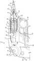
图1示出使用本发明的示例性医疗装置500在患者体内的目标位置处执行的示例性医疗手术。图2示出用于图1的医疗手术中的示例性医疗装置500。在下面的讨论中,将参考图1和图2两者。在一些实施例中,如图1所示,医疗装置500可通过输送镜1000的腔引入体内。任何合适的输送镜1000(诸如,例如,胃镜、结肠镜、支气管镜、喉镜、膀胱镜、十二指肠镜、肠镜、输尿管镜、导管等)可用于将医疗装置500引入体内。在一些实施例中,医疗装置500可配置为通过具有,例如,2.8mm直径腔的输送镜插入体内。如前所述,使用输送镜1000将医疗装置500插入体内不是必需的。例如,可以设想,在一些实施例中,医疗装置500可直接插入体内(例如,不使用输送镜)。公开的医疗装置500可用于在患者解剖结构的任何合适位置(诸如,例如,大肠的一些部分、小肠、盲肠、食道、胃肠道的其他部分、心血管、生殖等)执行任何合适的医疗手术。例如,一个或多个医疗装置500可用于可视化、切割、切除、激发、治疗、移除、连结和/或操纵腔内空间中的目标组织,或促进其处理。1 illustrates an exemplary medical procedure performed at a target location within a patient using an exemplary
在医疗手术期间,输送镜1000可通过自然孔口(嘴、直肠等)或切口插入患者体内,并推入,使得其远端1000A位于体内期望的工作部位(例如,组织损伤等)处。然后,位于医疗装置500的最远端处的末端执行器120通过输送镜1000的近端插入其腔中,并推入,使得末端执行器120延伸出输送镜1000的远端1000A至体内。例如,参考图1和图2所示的XYZ坐标系,当医疗装置500从近端推入到输送镜1000中时,医疗装置500的末端执行器120在-X方向上移出输送镜1000的远端1000A。即,通过将医疗装置500推入和拉出输送镜1000实现了医疗装置500的末端执行器120在工作部位处沿着X轴线的平移。通常,末端执行器120在YZ平面中的平移(即,在Y方向或Z方向上的移动,在本文中称为一侧至另一侧的运动)通过将输送镜1000的远端1000A从一侧移动到另一侧来实现。即,对经由输送镜插入体内的传统医疗装置的操纵主要是经由输送镜的操纵来实现的。相反地,在本发明的一些实施例中,公开的医疗装置500可独立于输送镜1000在目标部位处进行操纵(例如,朝向和远离组织移动、从一侧移动到另一侧、旋转、致动等)。因此,公开的医疗装置500的各方面可为用户提供独立于输送镜1000来单独控制医疗装置500的位置、方向、移动和致动中的一些或全部的能力。During a medical procedure, the
通常,公开的医疗装置500可包括适合于正在执行的医疗手术的任何类型的末端执行器120。例如,公开的医疗装置500可包括采用夹子、勒除器、抓握器、相机、照明装置、针、刀、剪刀、镊子、电外科刀(例如,内窥镜粘膜下剥离刀)等中一个或多个形式的末端执行器120。然而,为了简单起见,在下面的讨论中,具有抓握器配置的末端执行器120将用于描述本发明的各方面。然而,应注意,参考抓握器描述的概念可应用于具有任何类型的末端执行器120的内窥镜医疗装置500。医疗装置500的部件可由任何合适的生物相容性材料(诸如,例如,金属材料、塑料材料、形状记忆金属(诸如,镍钛诺)、形状记忆聚合物、聚合物、或生物相容性材料的任何组合)制成或包括其。In general, the disclosed
参考图2,医疗装置500可包括近侧操纵部分100和远侧插入部分200。操纵部分100包括手柄10,其具有可用于例如,在患者体内操纵医疗装置500的控件。手柄10配置为在使用装置500期间由用户(医疗专业人员等)握持,并可根据人为因素界面设计(HFID)原理进行配置。插入部分200包括从手柄10延伸到装置500的远侧部分250的柔性管状部分50(或芯)。应注意,远侧部分250在图2中被夸大地示出以清楚地示出该部分的结构特征。管状部分50的柔性特性使得其能够在装置500通过输送镜1000引入体内时弯曲和挠曲。除了其他区域之外,装置500的远侧部分250包括铰接区域60、旋转区域90和末端执行器120。稍后将详细描述远侧部分250的这些区域。Referring to FIG. 2 , a
手柄10包括主体12,其在套管帽20处连结到管状部分50。主体12包括抓握部分11,其通常成形为由用户的手(左手或右手)握持。主体12还支撑可用于操纵装置500的远侧部分250和末端执行器120的控制装置、致动装置或致动器。在下面的讨论中,这些致动装置将称为“旋钮”。然而,应注意,将致动装置称为旋钮仅仅是为了方便,而不是作为其几何形状的指示。在一些实施例中,手柄10上的致动装置可包括第一致动器(本文称为转向旋钮14)、第二致动器(本文称为旋转旋钮16)和第三致动器(本文称为致动旋钮16)。The
参考图2,在使用装置500期间,转向旋钮14可用于将装置500的末端执行器120和远端从一侧转向或移动至另一侧(例如,在YZ平面中的任何方向上)。旋转旋钮16可用于独立于远侧部分250旋转末端执行器120,例如,绕X轴进行。并且,致动旋钮18可用于致动例如,打开和关闭末端执行器120。通过在X方向上移动手柄10(例如,通过将装置500推入和推出输送镜1000),可在X方向上移动末端执行器120(连同装置500的远端)。并且如稍后将更详细描述的,管状部分50可例如通过旋转手柄10(这将使远侧部分250和末端执行器120一起旋转)绕X轴线旋转。2, during use of
应注意,尽管图2中示出了手柄10的具体形态,但这仅是示例性的。通常,手柄10可具有任何形态,并且其控制旋钮可具有任何合适的形态,并且可位于任何位置。在一些实施例中,手柄10的形状以及手柄10上的转向旋钮14、旋转旋钮16和致动旋钮18的位置可基于HFID原理确定。在一些实施例中,当手柄10的抓握部分11由用户的手抓握时,拇指可用于激活转向旋钮14,中指可用于激活致动旋钮18,并且食指可用于激活旋转旋钮16。在其他可能的改型中,在一些实施例中,手柄10上旋转旋钮16和致动旋钮18的位置可互换。应注意,当与已知的医疗装置和内窥镜的致动系统相比时,公开的手柄10上的致动系统(例如,转向旋钮14、旋转旋钮16和驱动旋钮18)具有许多优点。一个优点是公开的致动器(例如,转向旋钮14、旋转旋钮16和/或致动旋钮18)中的一些或全部使得能够实现转向线32、34和/或拉线36的长行程,这转变为在装置500远端处更多的运动。另一个优点是,与具有有限机械优势的已知装置和内窥镜的致动系统相比,公开的手柄10的致动器提供了机械优势。致动器增加的机械优势减少了致动致动器所需的力和工作量。It should be noted that although a specific configuration of
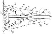
图3A至图3C是装置500的示例性手柄10的不同视图的图示。手柄10的主体12可包括两个部分或两个半部-第一部分12A和第二部分12B-当结合在一起时,其形成手柄10的两个相对侧。图3A是手柄10的侧视图,其中第二部分12B以阴影显示以说明手柄10内的部件和特征。并且,图3B和图3C分别是手柄10的第一和第二部分12A、12B的侧视图。在下面的讨论中,将参考图3A至图3C。当第一部分12A与第二部分12B结合以组装手柄10时,第一部分12A上的销24A与第二部分12B中对应的销槽24B接合(例如,形成干涉配合)以将两个部分连结在一起。两个部分12A和12B可通过其他方式,如压配合、胶合而结合在一起。第一和第二部分12A和12B包括凹部或空腔,其配置为支撑转向旋钮14、旋转旋钮16和致动旋钮18。当组装手柄10时:转向旋钮14支撑在第一和第二部分12A、12B的空腔14A和14B之间;旋转旋钮16支撑在第一和第二部分12A、12B的空腔16A和16B中;并且致动旋钮18A支撑在第一和第二部分12A、12B的空腔18A和18B之间。第一和第二部分12A、12B还包括外(例如,阳)螺纹20A、20B,其配置为与套管帽20上对应的螺纹接合以将套管帽20连结到手柄10。3A-3C are illustrations of different views of an
参考图3A,转向线32、34从紧邻套管帽20的端部延伸通过手柄10的主体12上的凹陷路径到达转向旋钮14。转向线32、34中每一根的一端连结到转向旋钮14,转向线32、34中每一根的相对端部连结到在装置500远侧部分250(图2)中的铰接帽68(见图7A)。通常,转向线32、34可以任何合适的方式,诸如,例如,通过压接、焊接、使用紧固件、机械锁定特征、打结等连结到转向旋钮14和铰接帽68。参考图3B和图3C,第一部分12A包括转向线槽32A、34A,第二部分12B包括转向线槽32B、34B,其一起配置为在手柄10组装好时接收转向线32、34。在一些实施例中,第一部分12A可包括位于转向线槽32A、34A上的销22A,第二部分12B可包括相应地定位的凹部22B,其配置为当手柄10组装好时接收这些销22A。销22A可包括在其基部处的横向路径或狭槽22C(见图4B),其在转向线槽32A、34A的上方延伸以允许转向线32、34通过其。Referring to FIG. 3A , the
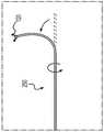
图4A是主体12支撑转向旋钮14的部分的放大图,图4B是主体12的第一部分12A对应部分的放大图。如图4A最佳所示,枢轴26从转向旋钮14的相对侧表面向外突出。当手柄10与定位在第一和第二部分12A、12B的转向旋钮空腔14A、14B中的转向旋钮14组装在一起时,枢轴26将接收在第一和第二部分12A、12B(见图4A)上的凹部26A、26B(见图3B、3C)中。在手柄10组装好后,转向旋钮14的延伸部14C从手柄10的主体12突出。为了致动转向旋钮14,用户可在延伸部14C上施加力(推或拉)以使转向旋钮14绕其枢轴26旋转(如图4A上的双向箭头所示)。当转向旋钮14被致动或绕其枢轴26旋转时,转向线32、34上造成的力(例如,张力)导致装置500的铰接区域60中的链节绕其各自的枢轴旋转,并导致装置500的远端从一侧移动到另一侧。例如,如图11A和图11B示意性所示,当转向旋钮14在一个方向上(例如,顺时针)旋转时,拉力(或张力)施加到转向线中的一根(例如,转向线32)上。并且,当转向旋钮14在相反方向上(例如,逆时针)旋转时,拉力施加到另一根转向线(例如,转向线34)上。铰接方向由转向线32或34压接在转向旋钮14上的位置控制。当转向线32压接到孔14E中并且转向线34压接到孔14D中时,转向旋钮14在顺时针方向上的旋转将转向线32置于张力下。在其他概念中,如果压接位置互换,转向线32压接在孔14D中并且转向线34在14E中,则转向旋钮14的顺时针旋转将转向线34置于张力下。如稍后将更详细描述的,当向转向线32施加张力时,铰接区域60在转向线32的方向上弯曲(或成曲线),并且当向转向线34施加张力时,铰接区域60在转向线34的方向上弯曲。由转向旋钮14的致动引起的铰接区域60的弯曲导致在装置500远端处的末端执行器120从一侧移动到另一侧。FIG. 4A is an enlarged view of a portion of the
在一些实施例中,类似于主体12,转向旋钮14也可包括可结合在一起以形成转向旋钮14的第一部分14A'和第二部分14B'。图4C和4D示出了示例性实施例中转向旋钮14的第一和第二部分14A'、14B'。如图4C所示,转向旋钮14的第一部分14A'可包括孔或空腔14D和14E,其配置为接收转向线32、34的锁定特征(未示出)并将转向线32、34连结到转向旋钮14。转向旋钮14的第二部分14B'可包括凹陷区域14D'和14E',其配置为接收转向线32、34被接收在第一部分14A'的空腔14D和14E中的锁定特征。在一些实施例中,这些锁定特征可包括压接件、锁定螺母或附接到转向线32、34中每一根的端部的另一特征。每根转向线32、34的锁定特征可与空腔14D和14E中不同的一个接合,以将转向线32、34两者连结到转向旋钮14。In some embodiments, similar to
应注意,上述转向旋钮14的几何形状、形态和特征仅是示例性的。通常,转向旋钮14可具有不同的形态,例如,如参考图10A至图10D所描述的。在一些实施例中,转向旋钮14可配置为操纵杆或具有表面特征以增加抓握力的柱状部件。如本领域普通技术人员认识到的,适于选择性地向转向线32、34施加张力的任何类型的致动装置都可用作手柄10的转向旋钮。通常,由具有任何尺寸的任何材料(例如,不锈钢、镍钛诺、尼龙等)制成的任何类型的线材(单股、多股等)都可用作转向线32、34。在一些实施例中,转向线32、34可涂覆有或包括由不同材料(例如,润滑材料)制成的套管。由于可与内窥镜医疗装置一起使用的转向线32、34在本领域中是已知的,因此本文不对其进行详细描述。It should be noted that the geometry, configuration and features of the steering
返回参考图3A,除了转向线32和34之外,芯线或拉线36(或控制元件)也延伸通过手柄10的主体12。拉线36和转向线32、34延伸通过的手柄10上的通道的尺寸可设置为使得这些线材自由地通过其各自的通道,而没有干扰。在一些实施例中,由诸如,例如,聚四氟乙烯(PTFE)的润滑材料制成的管可设置在或附接在这些通道中的一些或全部中,以促进线材在其中自由移动。与转向线32、34一样,拉线36也可包括任何类型的线(单股、多股等),其具有任何尺寸由任何材料(例如,不锈钢、镍钛诺、尼龙等)制成。在一些实施例中,拉线36可涂覆有或包括由不同材料(例如,润滑材料)制成的套管。Referring back to FIG. 3A , in addition to the
拉线36可连结到旋转旋钮16和致动旋钮18。在其近端,拉线36固定地连结(或附接)到套管42,其可旋转地连结到致动旋钮18。即,套管42连结到致动旋钮18,使得其可与旋转旋钮16中的方形套管38一起旋转并与致动旋钮18一起平移。拉线36可以任何方式(焊接、压接、胶合等)附接到套管42。在一些实施例中,拉线36可压接到套管42。套管42可以任何方式可旋转地定位在致动旋钮18中。拉线36从手柄10向远侧延伸通过套管帽20到装置500的远侧部分250(见图2)。在其远端,拉线36连结到末端执行器120,使得当致动旋钮18向前移动(即,向远侧移动)和向后移动(即,向近侧移动)时,末端执行器120操作(例如,在末端执行器120是抓握器的实施例中为打开和关闭)。Pull
拉线36还延伸通过旋转旋钮16中的通道16C。在一些实施例中,通道16C可具有方形截面形状。具有对应形状的海波管(例如,方形海波管38)可以可滑动地定位在通道16C中。即,方形海波管38配置为在旋转旋钮16的通道16C中来回滑动。方形海波管38可固定地连结(例如,压接)到延伸通过其的拉线36。由于通道16C和海波管38的方形截面形状,当旋转旋钮16旋转时,海波管38和拉线36与旋转旋钮16一起旋转,从而使末端执行器120独立于远侧轴250旋转。由于海波管38可滑动地连结到旋转旋钮16,当致动旋钮18来回移动时,海波管38和拉线36与致动旋钮18一起在旋转旋钮16中平移。由于套管42可旋转地连结到致动旋钮18,当旋转旋钮16旋转时,拉线36和套管42在致动旋钮18中旋转。Pull
应注意,上述海波管38和通道16C的具体配置仅是示例性的,许多变化都是可能的。例如,虽然通道16C和海波管38的截面形状描述为方形,但这仅仅是示例性的。通常,通道16C和海波管38可具有任何合适的非圆形形状(三角形、多边形、六边形、矩形等)。还应注意,上述拉线36至旋转旋钮16的连结仅是示例性的。通常,拉线36可以任何方式连结到旋转旋钮16,使得拉线36与旋转旋钮16一起旋转并与致动旋钮18一起平移。It should be noted that the specific configurations of hypotube 38 and channel 16C described above are exemplary only, and many variations are possible. For example, although the cross-sectional shapes of channel 16C and hypotube 38 are described as square, this is exemplary only. In general, channel 16C and hypotube 38 may have any suitable non-circular shape (triangular, polygonal, hexagonal, rectangular, etc.). It should also be noted that the above-described attachment of the
类似于转向旋钮14,旋转旋钮16也可具有两个部分或两个半部,当手柄10组装好时,其结合在一起以形成完整的旋转旋钮16。应注意,图3A示出了旋转旋钮16的一半,图2示出了完整的旋转旋钮16。旋转旋钮16的两个半部可具有配合特征,其彼此接合以在手柄10组装好时将两个半部连结在一起。当手柄10组装好时,这些配合特征还可帮助将主体12的两个部分12A和12B对齐在一起。在一些实施例中,如图3A所示,这些配合特征可包括销16A和具有对应形状的空腔16B(在旋转旋钮16的两个半部中),其彼此接合以在手柄10组装好时,将旋转旋钮16的两个半部连结在一起。参考图2,旋转旋钮16的外表面可具有在使用期间为用户提供抓握的特征(例如,凹槽等)。应注意,虽然旋转旋钮16示为具有在表面上的凹槽(或指轮)的柱状形态,但这仅是示例性的。如本领域普通技术人员认识的,旋转旋钮16可具有任何合适的形态。Similar to the steering
致动旋钮18使用户能够操作或致动装置500的末端执行器120。例如,在末端执行器120是具有在被致动时打开和关闭的钳口的抓握器的实施例中,致动旋钮18可用于打开和关闭钳口。例如,向近侧移动致动旋钮18可关闭钳口,沿相反的向远侧的方向上移动致动旋钮18可打开钳口(或反之亦然)。致动旋钮18包括用作用户接口(例如,手指接口)的空腔或狭槽18A。使用中,用户可将手指插过狭槽18A并向近侧和向远侧拉动和推动致动旋钮18以致动末端执行器120。致动旋钮18的行程(即,图3A中标记为A的长度)可使钳口打开和关闭达不同的量。例如,移动致动旋钮18例如,1/3A的距离可比移动钳口A的距离将末端执行器120的钳口打开和关闭更小的量。手柄10的主体12(例如,主体12的第一部分12A和第二部分12B)和致动旋钮18具有对应定位的配合特征,其彼此接合以使致动旋钮18能够在手柄10中预定义的路径(例如,线性路径等)中移动。这些配合特征可包括致动旋钮18上的线性空腔18B,以及主体12的第一和第二部分12A、12B上装配到空腔18B中的配合突出部12C。例如,当手柄10组装好时,第一和第二部分12A、12B的突出部12C结合以形成单个突出部,其装配到致动旋钮18的细长空腔18B中(见图3B、图3C),使得致动旋钮18能够沿着由空腔18B限定的路径滑动。致动旋钮18还可包括与手柄主体12上对应特征相配合以对齐手柄10上的致动旋钮18的附加特征(例如,突出部、空腔等)(图中未标出)。The
如前面解释的,致动旋钮18包括套管42,拉线36附接到该套管42。套管42可旋转地固定在形成于致动旋钮18中的空腔18C中。套管42以一种方式定位在空腔18C中,使得(a)当旋转旋钮16旋转时,套管42和拉线36可在致动旋钮18中一起旋转,并且(b)当致动旋钮18平移(向近侧和向远侧)时,套管42和拉线36与致动旋钮18一起移动。应注意,图3A中所示的致动旋钮18的形态仅仅是示例性的,医疗装置500可包括具有任何合适形态的致动旋钮18。As previously explained, the
如前面解释的,手柄10的拉线36和转向线32、34通过管状部分50延伸到装置500的远侧部分250。手柄10使用套管帽20连结到管状部分50。图4E是连结手柄10与管状部分50的示例性套管帽20的图示。并且,图4F是示例性实施例中套管帽20的截面视图。如图4E所示,在一些实施例中,套管帽20的螺纹螺钉(例如,阴螺纹螺钉)可与手柄主体12对应的螺纹螺钉(例如,阳螺纹螺钉)接合以将手柄10连结到管状部分50。应注意,尽管套管帽20描述为使用螺纹螺钉附接到手柄10,但这仅仅是示例性的。通常,套管帽20可以任何方式附接至手柄10(套管帽20上的阳螺纹螺钉使用销等与手柄10的阴螺纹螺钉接合)。当套管帽20连结到手柄10时,套管帽20的中心通道28可与手柄10的通道流体连结,拉线36和转向线32、34延伸通过该手柄10的通道。通道28具有阶梯式形态,其中紧邻手柄10的第一部分28A具有较大的宽度/直径,邻近管状部分50的第二部分28B具有较小的宽度/直径。在图4F所示的套管帽20的实施例中,通道28的第一部分28A具有方形(或矩形)形态,其具有较大的宽度;第二部分28B具有管状形态,其具有较小的宽度(或直径)。As previously explained, the
管状部分50的近端连结到线套管40,并且管状部分50的远端连结到在装置500远侧部分250中的铰接部分60。在一些实施例中,线套管40可固定地附接到(例如,压接到)管状部分50的最近端。线套管40可定位在套管帽20的第一部分28A中(见图4E)。线套管40可具有与通道28的第一部分28A(线套管40定位在其中)的形状或形态相似的形状或形态。即,在第一部分28A具有方形或矩形的实施例中,线套管40也具有对应的方形或矩形。线套管40的外宽度可小于(通道28的)第一部分28A的宽度并大于第二部分28B的宽度,使得当套管帽20附接到手柄10时,第二部分28B较小的宽度防止线套管40(和管状部分50)与套管帽20分开。由于第一部分28A的宽度大于线套管40的宽度,因此在线套管40和通道28中的套管帽20之间存在间隔或间隙。如图4E中使用双向箭头所示,当套管帽20连结到手柄10时,手柄10中的通道和通道28的第一部分28A共同形成组合通道,其具有比线套管40更大的宽度。例如,当装置500插入输送镜1000的腔内时,该组合通道使线套管40和管状部分50能够在套管帽20和手柄10的远端内自由平移(例如,线性地)。线套管40和管状部分50以这种方式自由平移的能力使得管状部分50延伸通过输送镜1000的曲折腔,但不会在其中导致张力。The proximal end of the
转向线32、34和拉线36从手柄10延伸通过管状部分50到管状部分50。线32、34、36延伸通过管状部分50,使得他们可相对于彼此并且独立于彼此移动(旋转、平移等)。例如,当转动转向旋钮14以向转向线32、34施加张力时,这些转向线32、34可在管状部分50中平移(即,相对于管状部分50平移)。类似地,当旋转旋转旋钮16以使拉线36旋转时,以及当致动旋钮18平移以使拉线36平移时,拉线36可在管状部分中旋转和平移,但不会使管状部分50移动。
如上面解释的,在一些实施例中,如图4F所示,(套管帽20的)通道28的第一部分28A具有方形或矩形形态。在一些这样的实施例中,定位在第一部分28A中的线套管40还可具有对应的方形(或矩形)形态,使得当手柄10旋转时,线套管40和连结到线套管40的管状部分50也与手柄10一起旋转。应注意,一般来说,通道28的第一部分28A和线套管40可具有任何形态(例如,三角形、多边形等),其使得手柄10能够旋转以使管状部分50旋转。As explained above, in some embodiments, as shown in Figure 4F, the
如上面解释的,拉线36的远端连结到末端执行器120,管状部分50的远端连结到铰接部分60(见图2)。由于延伸通过管状部分50的拉线36未连结到线套管40,因此当手柄10旋转时,线套管40、管状部分50、远侧部分250和远侧组件120一起旋转。如图11B和图11C示意性所示,用户可旋转转向旋钮14(例如,在顺时针方向)以在侧向进行铰接,并且手柄10可与铰接远侧部分250一起旋转以到达目标组织。即,类似地,当旋转旋钮16旋转以使拉线36旋转时,拉线36在管状部分50中旋转,但不会使管状部分50旋转。因此,旋转旋钮16的旋转使拉线36和末端执行器120独立于管状部分50旋转,并且手柄10的旋转使铰接区域60与末端执行器120一起旋转。如稍后解释的,旋转铰接区域60使得末端执行器120能够在YZ平面中在不同方向上从一侧移动到另一侧。As explained above, the distal end of
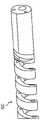
图5A示出示例性实施例中管状部分50的结构。管状部分50包括定位在线圈54内的多腔细长构件52。线圈54可包括不锈钢或另一种合适的材料(例如,镍钛诺等),其为管状部分50提供足够的刚度。在一些实施例中,线圈54可包括缠绕在细长构件52上的线材。在一些实施例中,线圈54可在没有多腔细长构件52的情况下使用,于是转向线32、34和拉线36可穿过线圈54,例如,如图5D所示。在一些实施例中,线圈54可附接到细长构件52的外表面,例如,通过压接、粘合剂、热缩等进行。线圈54的尺寸(厚度等)和/或其形态(节距等)可取决于管状部分50的期望刚度。细长构件52可包括延伸通过其的腔56A、56B和56C。转向线32、34和拉线36可从手柄10延伸通过这些腔56A、56B、56C到装置500的远侧部分250。例如,如图5A所示,转向线32和34可分别延伸通过腔56A和56B,并且拉线36可延伸通过腔56C。通常,这些腔56A至56C的尺寸可比延伸通过相应腔的线更大(例如,稍大),使得这些腔对通过该腔的线施加最小的干扰。在一些实施例中,管52可由润滑材料(诸如,例如,PTFE、
应注意,尽管图5A示出了细长构件52中腔56A至56C的特定形态,但这仅仅是示例性的。通常,腔56A至56C可以任何形态布置在细长构件52中。图5B和图5C示出示例性细长构件52,其具有以不同形态布置的腔。在图5B的实施例中,腔56A至56C以基本上三角形形态布置,在图5C的实施例中,腔56A至56C以线性形态进行布置。应注意,这些形态是示例性的,腔56A至56C的其他形态也是可能的。还应注意,尽管腔56A和56B示为基本上具有相同的尺寸,且腔56C示为大于腔56A和56B,但这仅是示例性的。通常,这些腔可具有任何尺寸(相同尺寸或不同尺寸)。It should be noted that although FIG. 5A shows a particular configuration of
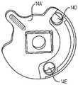
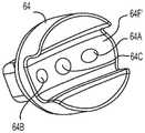
参考图2,在管状部分50的远端,管状部分50连接到远侧部分250的铰接区域60。图6A至图6C示出了铰接区域60的示例性实施例的不同视图。图6A示出处于弯曲形态中的铰接区域60的立体图,图6B和图6C分别示出铰接区域60的近侧和远侧区域的侧视图。铰接区域60使医疗装置500的末端执行器120能够在YZ平面中从一侧移动到另一侧(见图2和图6C)。铰接区域60包括近端帽62、远端盖66和定位在近端帽62和远端帽66之间的多个链节64。多个链节64一个堆叠在另一个上并连结在一起,使得每个链节64可相对于相邻链节64旋转。图6D和图6E示出近端帽62的相对端面的立体图,图6F和图6G示出链节64的相对端的立体图。Referring to FIG. 2 , at the distal end of the
如图6B和图6E中可见,近端帽62的近端附接到管状部分50的远端,并且其远端包括凹部62D。如图6F和图6G中最佳所示,链节64的远端包括凹部64D并且其近端包括突出区域64C。铰接区域60的多个链节64组装成使得一个链节64的突出区域64C定位在毗邻链节64的凹部64D中。突出区域64C和凹部64D的配合表面是弯曲的,使得每个链节64配置为绕其相邻链节64旋转。在其近端,链节64的突出区域64C类似地装配到近端帽62的凹部62D中,使得该链节64配置为绕近端帽62旋转。例如,链节64的突出区域64C的顶表面64F可具有对应于近端帽62和链节64的凹部62D、64D的基部62F、62F’的形状和/或曲率的形状和/或曲率。当链节64与近端帽62组装在一起时,顶表面64F和基部62F、62F'的曲率使得链节64能够相对于彼此旋转。远端帽66类似地连结到链节64(见图6C)。As can be seen in Figures 6B and 6E, the proximal end of the
通路62A、62B和62C穿过近端帽62(见图6D和图6E),通路64A、64B和64C穿过每个链节64(见图6F和图6G),通路66A、66B和66C穿过远端帽66(见图6C)。端帽62、66和链节64布置为使得通路62A、64A和66A对齐以形成对齐的通道,通路62B、64B和66B对齐以形成对齐的通道,且通路62C、64C、和66C对齐以形成对齐的通道。两根转向线32、34和拉线36穿过铰接区域60这些对齐的通道。例如,转向线32穿过由通路62A、64A和66A形成的通道,转向线34穿过由通路62B、64B和66B形成的通道,并且拉线36穿过由通路62C、64C和66C形成的通道。
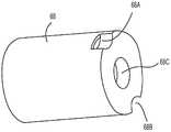
参考图6C,铰接帽68连结到在远端帽66远侧的铰接区域60。穿过铰接区域60的对齐通道的转向线32和34附接到铰接帽68。图7A示出装置500的远侧部分250的区域的放大视图,其示出了铰接帽68。并且,图7B示出示例性实施例中的铰接帽68。铰接帽68还包括与铰接区域60的对齐通道对齐的通路68A、68B和68C。从铰接区域60延伸的转向线32、34和拉线36通过这些通路68A、68B和68C进行引导。当拉线36经由通路68C穿过铰接帽68时,转向线32、34附接到铰接帽68。在一些实施例中,如图7A所示,转向线32、34可使用压接件(例如,压接件32’)或焊接件附接到铰接帽68。Referring to FIG. 6C , the hinged
当通过转动转向旋钮14向转向线32、34中的一个施加张力(或拉动转向线)时,链节64旋转,使得铰接区域60在拉动的转向线的方向上弯曲。尽管不是必需的,但在一些实施例中,转向线32、34在铰接区域60中穿过的通道可彼此相对地定位(例如,间隔约180°)。例如,如图6C所示,铰接区域60中的转向线32和34可沿着Z轴线对齐。在这样的实施例中,当拉动转向线34(或向转向线34施加张力)时,铰接区域60朝向转向线34弯曲并导致末端执行器120在-Z方向上移动。并且,当拉动转向线32时,铰接区域60朝向转向线32弯曲并导致末端执行器120在+Z方向上移动。即,转向旋钮14的致动将导致末端执行器120沿着Z轴移动。为了使末端执行器120沿着,例如,Y轴移动,手柄10可旋转90°以使管状部分50和铰接区域60旋转相同的角度,并使转向线32、34沿着Y轴对齐。当转向线32、34沿着Y轴对齐时转向旋钮14的致动将使末端执行器120沿着Y轴移动。以类似的方式,末端执行器120可通过旋转手柄10以在期望方向上对齐转向线32、34(在铰接区域60中)并致动转向旋钮14而在YZ平面中在任何方向上移动。应注意,由于管状部分50(和铰接区域60)的旋转独立于拉线36的旋转,所以当铰接区域60通过旋转手柄10而旋转时,拉线旋转和管状部分旋转都是彼此独立的。当手柄10旋转时,管状部分与远侧区域250和末端执行器120一起旋转。当旋转旋钮旋转16时,拉线36旋转,这仅使末端执行器120旋转,但不会使管状部分50和远侧区域250旋转,如图11E和图11F示意性所示。When tension is applied to one of the
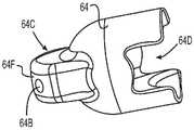
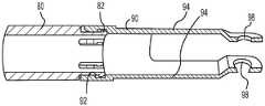
参考图6C,延伸出铰接帽68的拉线36穿过衬套80和U形夹90并例如,经由四杆链节(或另一种合适的)机构(未示出)连结到末端执行器120。如本领域技术人员应认识到的,四杆链节机构可配置为响应于拉线36沿着X轴的来回平移而打开和关闭末端执行器120的钳口。由于响应于拉线36的平移而致动末端执行器的四杆链节和其他合适机构在本领域中是已知的,因此本文不对其进行描述。Referring to Figure 6C, pull
再次参考图6C,末端执行器120在U形夹90的远端连结到U形夹90。U形夹90连结到衬套80,使得其可绕X轴在衬套80上旋转。U形夹90在衬套80上的旋转使得末端执行器120能够与拉线36一起独立于铰接区域60旋转。即,当转动手柄10的旋转旋钮16以旋转拉线36时,连结到拉线36远端的末端执行器120也旋转。可旋转地连结到衬套80的U形夹90使末端执行器120能够独立于装置500的致动区域60旋转。Referring again to FIG. 6C , the
图8A示出连结在一起的衬套80和U形夹90的截面视图。从图8A中可以看出,衬套80是在远端具有多个间隔开的狭缝的基本柱状部件。狭缝降低了衬套80在其远端的刚度,并使U形夹90的近端能够装配在衬套80的远端上。轴环82限定在衬套80的远端。U形夹90具有柱状区域,其在近端具有底切92(或凹槽)。U形夹90的柱状近端装配在衬套80的远端上方,其中衬套轴环82定位在U形夹底切92中。衬套80和U形夹90的尺寸设置为允许U形夹90在衬套80上自由旋转。U形夹90的远端包括一对凸缘94(或臂),其具有横向延伸通过其远端的空腔98。末端执行器120的钳口连结到凸缘94的空腔98。Figure 8A shows a cross-sectional view of the
如本领域技术人员应认识到的,公开的医疗装置的不同实施例可包括上述特征的许多变型。例如,在一些实施例中,如图8B所示,U形夹90'的近端可具有狭缝以降低其刚度(或增加其柔性)并使U形夹90'能够装配在衬套80'的远端上方。As will be appreciated by those skilled in the art, the different embodiments of the disclosed medical device may include many variations of the above-described features. For example, in some embodiments, as shown in Figure 8B, the proximal end of the clevis 90' may have a slit to reduce its stiffness (or increase its flexibility) and enable the clevis 90' to fit over the hub 80' above the far end.
在一些实施例中,公开的医疗装置可包括具有不同于上述形态的铰接区域。图9A至图9D示出可在公开的医疗装置中使用的铰接区域的不同示例性形态。在一些实施例中,如图9A所示,公开的医疗装置500的铰接区域60A可由柔性材料(诸如,例如,
在一些实施例中,如图9B所示,铰接区域60B可通过在柱状(或基本上柱状)构件中切割交替狭缝以使其具有柔性来形成。在一些实施例中,柱状构件可由生物相容性金属形成。然而,这不是必需的。如图9B所示,铰接区域60B上的相邻狭缝可沿着柱状构件的纵向轴线间隔开并可面向相反的方向。纵向通路可形成为通过柱状构件以用于转向线和推线。尽管图9B中示出了具有三角形截面形状的狭缝,但这仅是示例性的。通常,这些狭缝可具有任何形态。如图9A的铰接区域60A中,当拉动铰接区域60B的转向线32、34中的一个时,柔性铰接区域60B在拉动的转向线的方向上弯曲。并且,当释放转向线时,(用于形成铰接区域60B)的材料的弹性可使铰接区域60B返回到其原始形态(例如,线性的)。In some embodiments, as shown in Figure 9B, the hinge region 6OB may be formed by cutting alternating slits in a cylindrical (or substantially cylindrical) member to provide flexibility. In some embodiments, the columnar members may be formed from a biocompatible metal. However, this is not required. As shown in Figure 9B, adjacent slits on the
在一些实施例中,如图9C所示,铰接区域60C可具有螺旋形态。在一些实施例中,可形成具有螺旋形态的细长构件(通过任何工艺)并且具有柱状形态的端帽可附接到螺旋细长构件的相对端(在图9C中仅看到一端)。在一些实施例中,细长构件的中心部分(例如,两端之间的部分)可机加工(或以另一种方式加工)以具有螺旋形态。铰接区域60C可由任何生物相容性材料(例如,金属等)形成。用于转向线32、34和推线36的通路随后可形成为纵向地通过细长构件。在一些实施例中,螺旋细长构件的中心通道可用于延伸推线36,并且纵向通路可通过用于转向线32、34的螺旋构件形成。铰接区域60C的中心部分的螺旋形态可向铰接区域60C的该部分赋予柔性。当拉动转向线32、34中的一个时,铰接区域60C的柔性螺旋部分在拉动的转向线的方向上弯曲。并且,当释放拉动的转向线时,螺旋部分返回至其原始形态。In some embodiments, as shown in Figure 9C, the
在一些实施例中,铰接区域60D可通过提供通过柱状(或基本上柱状)构件的纵向间隔开的狭缝或狭槽来形成。柱状构件可由任何生物相容性材料形成,狭槽可具有任何形态,并且狭槽可以任何距离间隔开。通常,铰接区域60D的柱状构件可为柔性的。柔性可以是(用于形成铰接区域60D的)材料和/或狭槽的形态和间隔而产生的。纵向通道可通过用于转向线32、34和拉线36的柔性柱状构件形成。如在铰接区域60A至60C中的每一个中,中心定位的通路可用于使推线36通过,并且在中心通路任一侧上较小的通路可用于使转向线32、34通过。并且,当拉动转向线32、34中的一个时,柔性铰接区域60D在拉动的转向线的方向上弯曲。并且,当释放拉动的转向线时,铰接区域60D返回至其原始形态。In some embodiments, the
在一些实施例中,转向旋钮14、旋转旋钮16和/或致动旋钮18可具有与上述那些不同的形态。图10A示出采用转向旋钮140不同形态的医疗装置500。图10C示出与医疗装置500分开的转向旋钮140。转向旋钮140包括用于转向旋钮140旋转的多个支撑件140A(例如,拇指支撑件)。线保持器144(见图10A至图10B)连结到转向旋钮140,使得转向旋钮140的旋转使线保持器144旋转。图10B示出在示例性实施例中的线保持器144。装置500的转向线32、34连结到线保持器144。线保持器144包括盘状支撑区域144A,其具有从其延伸的轴144B。支撑区域144A的轴144B连结到转向旋钮140(例如,使用紧固件、粘合剂、摩擦等)。支撑区域144A包括与转向线32、34近端上的对应特征接合以将转向线32、34连结到线保持器144的特征。支撑区域144A的这些特征可包括孔或空腔144C,其接收附接到转向线32、34端部(例如,近端)的压接件146。图10D是附接到转向线32、34端部的示例性压接件146的示意性图示。如图10D所示,转向线32、34的端部插入压接件146的空腔146A中并施加一个或多个横向力F,以使压接件146的表面变形,并且将压接件146固定地附接到转向线32、34。然后,压接件146支撑在空腔144C中,并且转向线32、34通过手柄10的主体12中的通路延伸到装置500的远侧部分250,如前所述。In some embodiments, steering
在一些实施例中,如图10A所示,转向线32、34的近端可围绕线保持器144的支撑区域144A缠绕,其中压接件146位于其支撑在空腔144C中的最近端处。支撑区域144A可包括接收缠绕的转向线32、34的通道144D。在一些实施例中,如图10A所示,转向线32、34的近端可形成围绕支撑区域144A的一个环。尽管不是必需的,但是围绕支撑区域144A缠绕转向线32、34的近端可降低在操作期间在这些线32、34中产生扭结的可能性。如前所述,转向旋钮140在一个方向上的旋转在一根转向线(例如,转向线32)上施加拉力(或张力),并且转向旋钮140在相反方向上的旋转在另一根转向线(例如,转向线34)上施加了拉力。In some embodiments, as shown in FIG. 10A , the proximal ends of the
应注意,尽管上面已经描述了医疗装置500具有两根转向线32、34的示例性实施例,但这不是限制。通常,本发明的装置500可包括任何数量(例如,1、3、4等)的绕其铰接区域(60、60A等)布置的转向线。这些转向线可围绕铰接区域以任何形态(例如,角间隔)布置。例如,在一些实施例中,医疗装置500可仅包括单根(即,一根)转向线。在一些实施例中,通过使用转向线连同手柄10的旋转,单根转向线可用于在不同方向上弯曲装置500的铰接区域。例如,当手柄10定位在第一形态(例如,在图2所示的形态中)时拉动转向线可使装置500的铰接区域在第一方向(例如,在+Y方向)上弯曲。并且,旋转手柄10(例如,180°)以旋转铰接区域,随后拉动相同的转向线可使铰接区域在相反方向(例如,在-Y方向)上弯曲。It should be noted that although an exemplary embodiment of the
在一些实施例中,三根转向线可围绕铰接区域以约120°的角度间隔开。并且,在一些实施例中,四根转向线可围绕铰接区域以约90°的角度间隔开。这四根转向线可由相同或不同的转向旋钮致动。例如,第一对相对定位(例如,间隔180°)的转向线可附接到第一转向旋钮并由其致动,并且第二对相对定位的转向线可附接到第二转向旋钮并由其致动。在一根转向线上施加拉力会导致铰接区域在拉动的转向线的方向上弯曲。In some embodiments, the three steering lines may be spaced at an angle of about 120° around the hinge area. Also, in some embodiments, the four steering lines may be spaced at an angle of about 90° around the hinge area. The four steering wires can be actuated by the same or different steering knobs. For example, a first pair of oppositely positioned (eg, 180° apart) steering wires may be attached to and actuated by a first steering knob, and a second pair of oppositely positioned steering wires may be attached to and actuated by a second steering knob its actuation. Applying a pulling force on one steering wire will cause the hinged area to bend in the direction of the pulled steering wire.
如上面解释的,本发明的示例性医疗装置500具有彼此分离的多个独立自由度。具体地,在装置500的各种实施例中,独立自由度包括(参考图2):(a)末端执行器120可使用致动旋钮18致动(例如,打开和关闭);(b)末端执行器120可使用转向旋钮14在YZ平面中移动(例如,左右和上下);(c)末端执行器120可使用旋转旋钮16旋转(绕X轴顺时针和逆时针);(d)装置500的线圈或管状部分50可通过旋转手柄10而旋转(绕X轴顺时针和逆时针);以及(e)通过使手柄10在X方向上移动可使末端执行器120在X方向上移动。并且,这些自由度中的每一个都是独立的且彼此分离。在使用公开的装置500的示例性医疗手术期间,装置500的多个独立自由度使得其末端执行器120能够以独立于用于将装置500引入患者体内的输送镜的任何期望方式进行操纵。As explained above, the exemplary
现在将描述使用示例性公开的医疗装置500的示例性医疗手术(例如,内窥镜粘膜切除术)。由于这种医疗手术在本领域中是众所周知的,因此下面将描述手术仅突出公开装置的示例性特征的方面。在下面的讨论中,将参考图1、图2、图3A和图6C。输送镜1000(例如,内窥镜)可插入患者体内(例如,通过嘴插入患者的上胃肠道中)并定位成使其远端紧邻目标组织。内窥镜医疗装置500可通过输送镜1000的腔插入体内,并且其末端执行器120适当地定位在紧邻目标组织处。最初,装置500的铰接区域60中的转向线32、34可沿着,例如,Y轴对齐。当处于该取向中时,可致动(或转动)转向旋钮14以弯曲致动区域60并沿着Y轴移动末端执行器120。即,在一个方向上转动转向旋钮14将使铰接区域60弯曲,使得末端执行器120在+Y方向上移动,并且在相反方向上转动转向旋钮14将使铰接区域60在相反方向上弯曲,使得末端执行器120在-Y方向上移动。现在可转动旋转旋钮16以独立地旋转末端执行器120。由于末端执行器120的旋转与管状部分50和铰接区域60的旋转分离,旋转旋钮16的操作使末端执行器120旋转,但不会改变,例如,铰接区域60的弯曲形态。手柄10可旋转例如90°,以使铰接区域60旋转相同的角度,并且沿着Z轴对齐转向线32、34。现在可致动转向旋钮14以沿着Z轴弯曲铰接区域60,从而沿着该轴线移动末端执行器120。在该过程期间的任何时间,可激活致动旋钮18以打开和关闭末端执行器120的钳口。手柄10可在+/-X方向上移动,这将使末端执行器120在+/-方向上平移(进出内窥镜1000),如图11G中示意性示出的。An exemplary medical procedure (eg, endoscopic mucosal resection) using the exemplary disclosed
应注意,使用装置500的典型医疗手术可包括许多已知的附加(或替代)步骤,为了简洁起见,在上述描述中已省略了这些步骤。可省略或修改任何上述步骤,或者添加其他步骤,只要公开的医疗装置500的预期功能保持基本不变即可。此外,尽管在描述的医疗手术中描述或暗示了某个顺序,但通常,不需要按所述的顺序执行这些步骤。此外,所述的手术可并入本文未描述的更全面的医疗手术中。It should be noted that a typical medical
尽管本文参考了针对特定应用的说明性方面描述了本发明的原理,但应理解,本发明不限于此。本领域中具有普通技术并访问本文提供教导的人员将认识到额外的修改、应用、方面和等同物的替换都落在本文所述的各方面的范围内。因此,本发明不应被认为受前述描述的限制。Although the principles of the invention have been described herein with reference to illustrative aspects directed to particular applications, it should be understood that the invention is not limited thereto. Those of ordinary skill in the art and having access to the teachings provided herein will recognize additional modifications, applications, aspects, and substitutions of equivalents that fall within the scope of the aspects described herein. Accordingly, the present invention should not be considered limited by the foregoing description.
Claims (15)
Applications Claiming Priority (3)
| Application Number | Priority Date | Filing Date | Title |
|---|---|---|---|
| US201962946483P | 2019-12-11 | 2019-12-11 | |
| US62/946,483 | 2019-12-11 | ||
| PCT/IB2020/001038WO2021116767A1 (en) | 2019-12-11 | 2020-12-08 | Medical device with multiple degrees of freedom and related methods |
Publications (1)
| Publication Number | Publication Date |
|---|---|
| CN114760904Atrue CN114760904A (en) | 2022-07-15 |
Family
ID=74236233
Family Applications (1)
| Application Number | Title | Priority Date | Filing Date |
|---|---|---|---|
| CN202080084574.5APendingCN114760904A (en) | 2019-12-11 | 2020-12-08 | Medical device with multiple degrees of freedom and related methods |
Country Status (5)
| Country | Link |
|---|---|
| US (1) | US12390090B2 (en) |
| EP (1) | EP4072396A1 (en) |
| JP (1) | JP2023505345A (en) |
| CN (1) | CN114760904A (en) |
| WO (1) | WO2021116767A1 (en) |
Families Citing this family (11)
| Publication number | Priority date | Publication date | Assignee | Title |
|---|---|---|---|---|
| US12220538B2 (en) | 2008-12-08 | 2025-02-11 | Scientia Vascular, Inc. | Micro-fabricated intravascular devices having varying diameters |
| US11207502B2 (en) | 2016-07-18 | 2021-12-28 | Scientia Vascular, Llc | Guidewire devices having shapeable tips and bypass cuts |
| ES2966345T3 (en) | 2017-05-26 | 2024-04-22 | Scientia Vascular Inc | Microfabricated medical device with a non-helical cutting arrangement |
| US12178975B2 (en) | 2020-01-23 | 2024-12-31 | Scientia Vascular, Inc. | Guidewire having enlarged, micro-fabricated distal section |
| US12343485B2 (en) | 2020-01-23 | 2025-07-01 | Scientia Vascular, Inc. | High torque guidewire device |
| US11957323B2 (en) | 2020-02-18 | 2024-04-16 | Boston Scientific Medical Device Limited | Medical device handle assemblies and methods of using the same |
| US12296112B2 (en) | 2020-10-05 | 2025-05-13 | Scientia Vascular, Inc. | Microfabricated catheter devices with high axial strength |
| CN118234423A (en)* | 2021-06-28 | 2024-06-21 | 格朗皮创新公司 | Entry device |
| DE102021122445A1 (en)* | 2021-08-31 | 2023-03-02 | Hoya Corporation | Endoscope with glued traction cable |
| CN119562785A (en)* | 2022-06-10 | 2025-03-04 | 努瓦拉公司 | Steerable catheter device with video capability and method of treatment using the device |
| DE102023131722A1 (en)* | 2023-11-14 | 2025-05-15 | Epflex Feinwerktechnik Gmbh | Functional tube instrument with axial stroke actuation |
Citations (7)
| Publication number | Priority date | Publication date | Assignee | Title |
|---|---|---|---|---|
| US5374277A (en)* | 1992-10-09 | 1994-12-20 | Ethicon, Inc. | Surgical instrument |
| US20100249497A1 (en)* | 2009-03-30 | 2010-09-30 | Peine William J | Surgical instrument |
| US20110106073A1 (en)* | 2009-10-30 | 2011-05-05 | Tyco Healthcare Group Lp | Jaw Roll Joint |
| US20130296878A1 (en)* | 2011-01-25 | 2013-11-07 | Taewoong Medical Co., Ltd. | Medical snare |
| CN104582606A (en)* | 2012-06-29 | 2015-04-29 | 伊西康内外科公司 | Closed Feedback Control for Electrosurgical Devices |
| US20180132923A1 (en)* | 2016-11-16 | 2018-05-17 | Boston Scientific Scimed, Inc. | Rotatable snares and related methods |
| CN108472055A (en)* | 2015-10-20 | 2018-08-31 | 卢门迪公司 | Medical instrument for performing minimally invasive surgery |
Family Cites Families (3)
| Publication number | Priority date | Publication date | Assignee | Title |
|---|---|---|---|---|
| US7951165B2 (en)* | 2003-08-18 | 2011-05-31 | Boston Scientific Scimed, Inc. | Endoscopic medical instrument and related methods of use |
| US8771260B2 (en) | 2008-05-30 | 2014-07-08 | Ethicon Endo-Surgery, Inc. | Actuating and articulating surgical device |
| JP6518403B2 (en)* | 2011-02-18 | 2019-05-22 | インテュイティブ サージカル オペレーションズ, インコーポレイテッド | Fusion and cutting surgical instruments and related methods |
- 2020
- 2020-12-08WOPCT/IB2020/001038patent/WO2021116767A1/ennot_activeCeased
- 2020-12-08CNCN202080084574.5Apatent/CN114760904A/enactivePending
- 2020-12-08USUS17/783,932patent/US12390090B2/enactiveActive
- 2020-12-08JPJP2022534622Apatent/JP2023505345A/enactivePending
- 2020-12-08EPEP20845692.1Apatent/EP4072396A1/ennot_activeWithdrawn
Patent Citations (7)
| Publication number | Priority date | Publication date | Assignee | Title |
|---|---|---|---|---|
| US5374277A (en)* | 1992-10-09 | 1994-12-20 | Ethicon, Inc. | Surgical instrument |
| US20100249497A1 (en)* | 2009-03-30 | 2010-09-30 | Peine William J | Surgical instrument |
| US20110106073A1 (en)* | 2009-10-30 | 2011-05-05 | Tyco Healthcare Group Lp | Jaw Roll Joint |
| US20130296878A1 (en)* | 2011-01-25 | 2013-11-07 | Taewoong Medical Co., Ltd. | Medical snare |
| CN104582606A (en)* | 2012-06-29 | 2015-04-29 | 伊西康内外科公司 | Closed Feedback Control for Electrosurgical Devices |
| CN108472055A (en)* | 2015-10-20 | 2018-08-31 | 卢门迪公司 | Medical instrument for performing minimally invasive surgery |
| US20180132923A1 (en)* | 2016-11-16 | 2018-05-17 | Boston Scientific Scimed, Inc. | Rotatable snares and related methods |
Also Published As
| Publication number | Publication date |
|---|---|
| US20230010697A1 (en) | 2023-01-12 |
| WO2021116767A1 (en) | 2021-06-17 |
| JP2023505345A (en) | 2023-02-08 |
| EP4072396A1 (en) | 2022-10-19 |
| US12390090B2 (en) | 2025-08-19 |
Similar Documents
| Publication | Publication Date | Title |
|---|---|---|
| CN114760904A (en) | Medical device with multiple degrees of freedom and related methods | |
| US7927327B2 (en) | Medical instrument having an articulatable end effector | |
| NL2021823B1 (en) | Steerable instrument comprising a tube element | |
| US9221179B2 (en) | Articulating mechanism | |
| US20090259141A1 (en) | Steerable tool guide for use with flexible endoscopic medical devices | |
| US20090299143A1 (en) | Actuating and articulating surgical device | |
| US20250268460A1 (en) | Medical articulation devices and methods of using the same | |
| US12390205B2 (en) | Medical device handle assemblies and methods of using the same | |
| CN116249473A (en) | Medical systems, devices, and related methods | |
| JP2025109900A (en) | Medical articulation device and method of using same - Patents.com | |
| US20220095888A1 (en) | Medical systems, devices, and related methods | |
| CN117561035A (en) | Medical systems, devices and related methods | |
| US20250169683A1 (en) | Medical systems, device, and related methods thereof |
Legal Events
| Date | Code | Title | Description |
|---|---|---|---|
| PB01 | Publication | ||
| PB01 | Publication | ||
| SE01 | Entry into force of request for substantive examination | ||
| SE01 | Entry into force of request for substantive examination | ||
| TA01 | Transfer of patent application right | Effective date of registration:20240407 Address after:Galway Applicant after:Boston Scientific Medical Devices Ltd. Country or region after:Ireland Address before:Galway Applicant before:BOSTON SCIENTIFIC LTD. Country or region before:Ireland | |
| TA01 | Transfer of patent application right |