CN114759899A - Low-insertion-loss acoustic wave band-pass filter and implementation method thereof - Google Patents
Low-insertion-loss acoustic wave band-pass filter and implementation method thereofDownload PDFInfo
- Publication number
- CN114759899A CN114759899ACN202110024640.6ACN202110024640ACN114759899ACN 114759899 ACN114759899 ACN 114759899ACN 202110024640 ACN202110024640 ACN 202110024640ACN 114759899 ACN114759899 ACN 114759899A
- Authority
- CN
- China
- Prior art keywords
- acoustic wave
- bandpass filter
- resonator
- parallel
- wave bandpass
- Prior art date
- Legal status (The legal status is an assumption and is not a legal conclusion. Google has not performed a legal analysis and makes no representation as to the accuracy of the status listed.)
- Pending
Links
Images


Classifications
- H—ELECTRICITY
- H03—ELECTRONIC CIRCUITRY
- H03H—IMPEDANCE NETWORKS, e.g. RESONANT CIRCUITS; RESONATORS
- H03H9/00—Networks comprising electromechanical or electro-acoustic elements; Electromechanical resonators
- H03H9/46—Filters
- H03H9/54—Filters comprising resonators of piezoelectric or electrostrictive material
- H03H9/547—Notch filters, e.g. notch BAW or thin film resonator filters
- H—ELECTRICITY
- H03—ELECTRONIC CIRCUITRY
- H03H—IMPEDANCE NETWORKS, e.g. RESONANT CIRCUITS; RESONATORS
- H03H9/00—Networks comprising electromechanical or electro-acoustic elements; Electromechanical resonators
- H03H9/02—Details
- H—ELECTRICITY
- H03—ELECTRONIC CIRCUITRY
- H03H—IMPEDANCE NETWORKS, e.g. RESONANT CIRCUITS; RESONATORS
- H03H9/00—Networks comprising electromechanical or electro-acoustic elements; Electromechanical resonators
- H03H9/02—Details
- H03H9/02007—Details of bulk acoustic wave devices
- H03H9/02086—Means for compensation or elimination of undesirable effects
- H—ELECTRICITY
- H03—ELECTRONIC CIRCUITRY
- H03H—IMPEDANCE NETWORKS, e.g. RESONANT CIRCUITS; RESONATORS
- H03H9/00—Networks comprising electromechanical or electro-acoustic elements; Electromechanical resonators
- H03H9/46—Filters
- H03H9/54—Filters comprising resonators of piezoelectric or electrostrictive material
- H03H9/58—Multiple crystal filters
- H03H9/582—Multiple crystal filters implemented with thin-film techniques
- H03H9/586—Means for mounting to a substrate, i.e. means constituting the material interface confining the waves to a volume
- H03H9/588—Membranes
- H—ELECTRICITY
- H03—ELECTRONIC CIRCUITRY
- H03H—IMPEDANCE NETWORKS, e.g. RESONANT CIRCUITS; RESONATORS
- H03H9/00—Networks comprising electromechanical or electro-acoustic elements; Electromechanical resonators
- H03H9/46—Filters
- H03H9/54—Filters comprising resonators of piezoelectric or electrostrictive material
- H03H9/58—Multiple crystal filters
- H03H9/582—Multiple crystal filters implemented with thin-film techniques
- H03H9/586—Means for mounting to a substrate, i.e. means constituting the material interface confining the waves to a volume
- H03H9/589—Acoustic mirrors
- H—ELECTRICITY
- H03—ELECTRONIC CIRCUITRY
- H03H—IMPEDANCE NETWORKS, e.g. RESONANT CIRCUITS; RESONATORS
- H03H9/00—Networks comprising electromechanical or electro-acoustic elements; Electromechanical resonators
- H03H9/02—Details
- H03H2009/02165—Tuning
- H03H2009/02173—Tuning of film bulk acoustic resonators [FBAR]
Landscapes
- Physics & Mathematics (AREA)
- Acoustics & Sound (AREA)
- Chemical & Material Sciences (AREA)
- Crystallography & Structural Chemistry (AREA)
- Piezo-Electric Or Mechanical Vibrators, Or Delay Or Filter Circuits (AREA)
Abstract
Description
Translated fromChinese技术领域technical field
本发明涉及无线通信技术领域,尤其涉及一种低插损声波带通滤波器 及其实现方法。The present invention relates to the technical field of wireless communication, and in particular, to a low insertion loss acoustic wave bandpass filter and an implementation method thereof.
背景技术Background technique
手持移动通信产品正在迅速地往小型化和轻便化发展,而随着这些产 品尺寸的减小,价格也持续下降,但功能却逐渐增强。在这微型化的发展浪 潮中,作为无线通信系统的关键部件,高性能的射频滤波器扮演着极重要的 角色。滤波器厂商面临着在不改变甚至提高滤波器性能的前提下进一步缩 小滤波器体积的任务。而由于手持移动通信产品中各类耗能应用和器件的 不断增加,使得滤波器的低插入损耗对延长通话时间和电池寿命变得非常 重要。Handheld mobile communication products are rapidly becoming smaller and lighter, and as the size of these products decreases, prices continue to drop, but functions are gradually enhanced. In this wave of miniaturization, as a key component of wireless communication systems, high-performance RF filters play an extremely important role. Filter manufacturers are faced with the task of further reducing filter size without changing or even improving filter performance. And due to the increasing variety of energy-consuming applications and devices in handheld mobile communication products, low insertion loss of filters is very important to prolong talk time and battery life.
利用谐振器设计射频滤波器电路的拓扑结构主要有梯形结构和网格状 结构,目前在高性能射频滤波器的设计中,梯形结构的设计方法较为流行。The topological structures of RF filter circuits designed by using resonators mainly include trapezoidal structure and grid-like structure. At present, in the design of high-performance RF filters, the design method of trapezoidal structure is more popular.
在传统梯形结构声波带通滤波器中,所有谐振器组的频率匹配点需要 保持严格一致,才能实现比较优良的插损特性,经薄膜体声波谐振器级联形 成滤波器时,必须要对串联单元和并联单元的频率匹配点做优化,然而工艺 过程不可避免地会引起频率波动,谐振器组的损耗会在频率匹配点处叠加, 导致滤波器通带中心形成凹陷,使得产品性能下降。In the traditional trapezoidal structure acoustic wave bandpass filter, the frequency matching points of all resonator groups need to be strictly consistent to achieve relatively good insertion loss characteristics. The frequency matching point of the unit and the parallel unit is optimized. However, the process will inevitably cause frequency fluctuation, and the loss of the resonator group will be superimposed at the frequency matching point, resulting in the formation of a depression in the center of the filter passband, which will degrade the product performance.
发明内容SUMMARY OF THE INVENTION
本发明的目的在于提供一种低插损声波带通滤波器及其实现方法,通 过优化调节滤波器中谐振器组的频率匹配点,使每个谐振器组的频率匹配 点均在通带内合理分布,避免现有技术中谐振器组带来的损耗叠加,可以有 效降低滤波器通带中心的插入损耗。The purpose of the present invention is to provide a low insertion loss acoustic wave bandpass filter and a method for realizing the same. Reasonable distribution can avoid the superposition of losses caused by the resonator group in the prior art, and can effectively reduce the insertion loss in the center of the passband of the filter.
为达到上述目的,本发明提供了一种低插损声波带通滤波器,包括级联 的多个声波带通滤波器单元;For achieving the above object, the invention provides a kind of low insertion loss acoustic wave bandpass filter, comprising multiple acoustic wave bandpass filter units of cascade connection;
所述声波带通滤波器单元包括一个串联谐振器和一个并联谐振器;The acoustic wave bandpass filter unit includes a series resonator and a parallel resonator;
所述并联谐振器的第一端接地,所述并联谐振器的第二端连接所述串 联谐振器的任一端;多个所述声波带通滤波器单元中的每个声波带通滤波 器单元的连接方式是一致的;The first end of the parallel resonator is grounded, and the second end of the parallel resonator is connected to either end of the series resonator; each acoustic wave bandpass filter unit in the plurality of the acoustic wave bandpass filter units The connection method is the same;
一个所述声波带通滤波器单元具有一个匹配频率,所述级联的多个声 波带通滤波器单元具有至少两个不同的匹配频率;A described acoustic wave bandpass filter unit has a matching frequency, and a plurality of acoustic wave bandpass filter units of the cascade have at least two different matching frequencies;
所述声波带通滤波器单元的匹配频率是由所述声波带通滤波器单元内 的串联谐振频率和并联谐振频率确定的,且所述串联谐振频率和所述并联 谐振频率的差值小于等于预设差值。The matching frequency of the acoustic wave bandpass filter unit is determined by the series resonance frequency and the parallel resonance frequency in the acoustic wave bandpass filter unit, and the difference between the series resonance frequency and the parallel resonance frequency is less than or equal to Preset difference.
可选地,一个所述声波带通滤波器单元内的所述串联谐振器和/或所述 并联谐振器采用薄膜体声波谐振器;Optionally, the series resonator and/or the parallel resonator in a described acoustic wave bandpass filter unit adopts a thin film bulk acoustic wave resonator;
所述薄膜体声波谐振器包括第一主谐振区域和第一次谐振区域,所述 第一主谐振区域具有第一占空比η1,所述第一次谐振区域具有第二占空比 η2;The thin film bulk acoustic resonator includes a first main resonance region and a first secondary resonance region, the first main resonance region has a first duty cycle η1 , and the first secondary resonance region has a second duty cycle η2 ;
所述声波带通滤波器单元内的所述串联谐振频率和所述并联谐振频率 的改变分别通过调节所述第一占空比η1和/或所述第二占空比η2实现。The change of the series resonance frequency and the parallel resonance frequency in the acoustic wave bandpass filter unit is achieved by adjusting the first duty cycle η1 and/or the second duty cycle η2 , respectively.
可选地,一个所述声波带通滤波器单元内的所述串联谐振器和/或所述 并联谐振器采用薄膜体声波谐振器;Optionally, the series resonator and/or the parallel resonator in a described acoustic wave bandpass filter unit adopts a thin film bulk acoustic wave resonator;
所述薄膜体声波谐振器包括第二主谐振区域和第二次谐振区域,所述 第二次谐振区域包含厚度d2和宽度w的特征;The thin-film bulk acoustic wave resonator includes a second main resonance region and a second secondary resonance region, and the second secondary resonance region includes features of thickness d2 and width w;
所述声波带通滤波器单元内的所述并联谐振频率的改变通过调节所述 厚度d2和/或所述宽度w实现。The change of the parallel resonance frequency in the acoustic bandpass filter unit is achieved by adjusting the thickness d2 and/or the width w.
本发明还提供了一种低插损声波带通滤波器的实现方法,包括:The present invention also provides a method for implementing a low insertion loss acoustic wave bandpass filter, including:
利用一个串联谐振器和一个并联谐振器构成一个声波带通滤波器单元;Using a series resonator and a parallel resonator to form an acoustic wave bandpass filter unit;
级联多个所述声波带通滤波器单元;cascade a plurality of said acoustic wave bandpass filter units;
其中,一个所述声波带通滤波器单元具有一个匹配频率,所述级联的多 个声波带通滤波器单元具有至少两个不同的匹配频率;Wherein, a described acoustic wave bandpass filter unit has a matching frequency, and the multiple acoustic wave bandpass filter units of the cascade have at least two different matching frequencies;
所述声波带通滤波器单元的匹配频率是由所述声波带通滤波器单元内 的串联谐振频率和并联谐振频率确定的,且所述串联谐振频率和所述并联 谐振频率的差值小于等于预设差值。The matching frequency of the acoustic wave bandpass filter unit is determined by the series resonance frequency and the parallel resonance frequency in the acoustic wave bandpass filter unit, and the difference between the series resonance frequency and the parallel resonance frequency is less than or equal to Preset difference.
可选地,所述并联谐振器的第一端接地,所述并联谐振器的第二端连接 所述串联谐振器的任一端,形成一个所述声波带通滤波器单元;多个所述声 波带通滤波器单元中的每个声波带通滤波器单元的连接方式是一致的。Optionally, the first end of the parallel resonator is grounded, and the second end of the parallel resonator is connected to either end of the series resonator to form one acoustic wave bandpass filter unit; a plurality of the acoustic wave The connection mode of each acoustic bandpass filter unit in the bandpass filter unit is consistent.
可选地,一个所述声波带通滤波器单元内的所述串联谐振器和/或所述 并联谐振器采用薄膜体声波谐振器;Optionally, the series resonator and/or the parallel resonator in a described acoustic wave bandpass filter unit adopts a thin film bulk acoustic wave resonator;
所述薄膜体声波谐振器包括第一主谐振区域和第一次谐振区域,所述 第一主谐振区域具有第一占空比η1,所述第一次谐振区域具有第二占空比 η2;The thin film bulk acoustic resonator includes a first main resonance region and a first secondary resonance region, the first main resonance region has a first duty cycle η1 , and the first secondary resonance region has a second duty cycle η2 ;
所述声波带通滤波器单元内的所述串联谐振频率和所述并联谐振频率 的改变分别通过调节所述第一占空比η1和/或所述第二占空比η2实现。The change of the series resonance frequency and the parallel resonance frequency in the acoustic wave bandpass filter unit is achieved by adjusting the first duty cycle η1 and/or the second duty cycle η2 , respectively.
可选地,所述声波带通滤波器单元内的所述串联谐振频率和所述并联 谐振频率的改变分别通过调节所述第一占空比η1和/或所述第二占空比η2实现,包括:Optionally, the series resonant frequency and the parallel resonant frequency in the acoustic wave bandpass filter unit are changed by adjusting the first duty cycle η1 and/or the second duty cycle η respectively.2 implementations, including:
若所述级联的多个声波带通滤波器单元具有五个匹配频率f1、f2、f3、 f4和f5,且所述五个匹配频率依次相差13MHz,所述串联谐振频率对所述 第一占空比η1变化量的平均值为13MHz/0.1,则确定所述f1、f2、f3、f4和 f5对应的串联谐振器的第一占空比

根据所述f1、f2、f3、f4和f5分别确定对应的并联谐振器的第二占空比

基于确定的所述


可选地,一个所述声波带通滤波器单元内的所述串联谐振器和/或所述 并联谐振器采用薄膜体声波谐振器;Optionally, the series resonator and/or the parallel resonator in a described acoustic wave bandpass filter unit adopts a thin film bulk acoustic wave resonator;
所述薄膜体声波谐振器包括第二主谐振区域和第二次谐振区域,所述 第二次谐振区域包含厚度d2和宽度w的特征;The thin-film bulk acoustic wave resonator includes a second main resonance region and a second secondary resonance region, and the second secondary resonance region includes features of thickness d2 and width w;
所述声波带通滤波器单元内的所述并联谐振频率的改变通过调节所述 厚度d2和/或所述宽度w实现。The change of the parallel resonance frequency in the acoustic bandpass filter unit is achieved by adjusting the thickness d2 and/or the width w.
可选地,所述声波带通滤波器单元内的所述并联谐振频率的改变通过 调节所述厚度d2和/或所述宽度w实现,包括:Optionally, the change of the parallel resonance frequency in the acoustic wave bandpass filter unit is achieved by adjusting the thicknessd2 and/or the width w, including:
若所述级联的多个声波带通滤波器单元具有五个匹配频率f1、f2、f3、 f4和f5,且所述五个匹配频率依次相差13MHz,所述并联谐振频率对有效 面积A变化量的平均值为3.33MHz/1000μm2,其中,所述有效面积A为所 述厚度d2和所述宽度w的乘积,则确定所述f1、f2、f3、f4和f5对应的并联 谐振器的有效面积A201、A202、A203、A204和A205分别为700μm2、4600μm2、 8500μm2、12400μm2和16300μm2;If the cascaded multiple acoustic wave bandpass filter units have five matching frequencies f1 , f2 , f3 , f4 and f5 , and the five matching frequencies differ by 13 MHz in sequence, the parallel resonance frequency The average value of the variation of the effective area A is 3.33MHz/1000μm2 , wherein the effective area A is the product of the thickness d2 and the width w, then determine the f1 , f2 , f3 , The effective areas A201 , A202 , A203 , A204 and A205 of the parallel resonators corresponding to f4 and f5 are respectively 700 μm2 , 4600
设置所述厚度d2为500nm,根据所述有效面积A201、A202、A203、A204和A205分别确定对应的w201、w202、w203、w204和w205;The thickness d2 is set to 500 nm, and corresponding w201 , w202 , w203 , w204 and w205 are respectively determined according to the effective areas A201 , A202 , A203 , A204 and A205 ;
基于确定的所述w201、所述w202、所述w203、所述w204和所述w205,调整光 刻板中对应的图形区域,通过一次刻蚀实现多个所述并联谐振频率的差异 调节。Based on the determined w201 , the w202 , the w203 , the w204 and the w205 , the corresponding pattern areas in the reticle are adjusted, and a plurality of parallel resonance frequencies are achieved by one etching. differential adjustment.
可选地,所述薄膜体声波谐振器还包括基底和谐振器堆叠结构;Optionally, the thin film bulk acoustic resonator further includes a substrate and a resonator stack structure;
所述基底上与所述谐振器堆叠结构连接的一面设有反射镜,所述反射 镜为空腔结构或布拉格反射器;The side connected with the resonator stack structure on the substrate is provided with a reflector, and the reflector is a cavity structure or a Bragg reflector;
所述谐振器堆叠结构包括第一电极层、压电薄膜层和第二电极层,所述 第一电极层、所述压电薄膜层和所述第二电极层依次层叠连接。The resonator stack structure includes a first electrode layer, a piezoelectric thin film layer, and a second electrode layer, and the first electrode layer, the piezoelectric thin film layer, and the second electrode layer are stacked and connected in sequence.
与现有技术相比,本发明的技术方案具有如下有益效果:Compared with the prior art, the technical scheme of the present invention has the following beneficial effects:
(1)本发明的低插损声波带通滤波器及其实现方法通过优化调节滤波 器中谐振器组的频率匹配点,使每个谐振器组的频率匹配点均在通带内合 理分布,避免现有技术中谐振器组带来的损耗叠加,可以有效降低滤波器通 带中心的插入损耗;(1) The low insertion loss acoustic wave bandpass filter of the present invention and its realization method adjust the frequency matching point of the resonator group in the filter optimally, so that the frequency matching point of each resonator group is reasonably distributed in the passband, Avoid the superposition of losses caused by the resonator group in the prior art, and can effectively reduce the insertion loss in the center of the passband of the filter;
(2)本发明的低插损声波带通滤波器及其实现方法通过调节谐振器的 占空比或者次谐振区域的有效面积的参数,通过一次刻蚀即可实现多个谐 振频率的差异调节,无需额外的工艺步骤,避免每个谐振器依次调节,可以 降低制备工艺的难度及成本;(2) The low insertion loss acoustic wave bandpass filter of the present invention and its realization method can realize the differential adjustment of multiple resonant frequencies by adjusting the duty cycle of the resonator or the parameters of the effective area of the sub-resonant region by one etching , no additional process steps are required, and each resonator is prevented from being adjusted in sequence, which can reduce the difficulty and cost of the preparation process;
(3)本发明的低插损声波带通滤波器及其实现方法在实现串联谐振频 率和并联谐振器频率差异微调的同时,使谐振器具有较高的Q值,可以减 少声波的横向泄漏,进一步降低级联后滤波器的通带插入损耗。(3) The low-insertion-loss acoustic band-pass filter of the present invention and its realization method realize the fine-tuning of the frequency difference between the series resonant frequency and the parallel resonator, make the resonator have a higher Q value, and can reduce the lateral leakage of the acoustic wave, Further reduce the passband insertion loss of the cascaded filters.
附图说明Description of drawings
为了更清楚地说明本发明实施例中的技术方案,下面将对实施例描述 中所需要使用的附图作简单地介绍,显而易见地,下面描述中的附图仅仅是 本发明的一些实施例,对于本领域普通技术人员来讲,在不付出创造性劳动 的前提下,还可以根据这些附图获得其他的附图。In order to illustrate the technical solutions in the embodiments of the present invention more clearly, the following briefly introduces the accompanying drawings used in the description of the embodiments. Obviously, the accompanying drawings in the following description are only some embodiments of the present invention. For those of ordinary skill in the art, other drawings can also be obtained from these drawings without creative effort.
图1是现有技术的梯形结构带通滤波器的频率匹配点示意图;1 is a schematic diagram of a frequency matching point of a trapezoidal structure bandpass filter in the prior art;
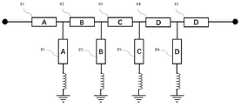
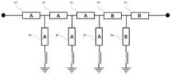
图2是本申请实施例的一种可选的梯形结构带通滤波器的方框图;2 is a block diagram of an optional trapezoidal structure bandpass filter according to an embodiment of the present application;
图3是本申请实施例的一种可选的梯形结构带通滤波器的频率匹配点 示意图;Fig. 3 is the frequency matching point schematic diagram of a kind of optional trapezoidal structure bandpass filter of the embodiment of the present application;
图4是本申请实施例的一种可选的梯形结构带通滤波器的频率匹配点 示意图;Fig. 4 is the frequency matching point schematic diagram of a kind of optional trapezoidal structure bandpass filter of the embodiment of the present application;
图5是本申请实施例的一种可选的梯形结构带通滤波器的频率响应曲 线图;Fig. 5 is the frequency response curve diagram of a kind of optional trapezoidal structure bandpass filter of the embodiment of the present application;
图6是本申请实施例的一种可选的薄膜体声波谐振器的结构示意图;6 is a schematic structural diagram of an optional thin-film bulk acoustic resonator according to an embodiment of the present application;
图7是本申请实施例的一种可选的薄膜体声波谐振器的结构示意图;7 is a schematic structural diagram of an optional thin-film bulk acoustic resonator according to an embodiment of the present application;
图8是本申请实施例的一种可选的梯形结构带通滤波器的方框图;8 is a block diagram of an optional trapezoidal structure bandpass filter according to an embodiment of the present application;
图9是本申请实施例的一种可选的梯形结构带通滤波器的方框图;9 is a block diagram of an optional trapezoidal structure bandpass filter according to an embodiment of the present application;
图10是本申请实施例的一种可选的梯形结构带通滤波器的方框图。FIG. 10 is a block diagram of an optional ladder structure bandpass filter according to an embodiment of the present application.
具体实施方式Detailed ways
下面将结合本发明实施例中的附图,对本发明实施例中的技术方案进 行清楚、完整地描述,显然,所描述的实施例仅仅是本发明一部分实施例, 而不是全部的实施例。基于本发明中的实施例,本领域普通技术人员在没有 做出创造性劳动的前提下所获得的所有其他实施例,都属于本发明保护的 范围。The technical solutions in the embodiments of the present invention will be clearly and completely described below with reference to the accompanying drawings in the embodiments of the present invention. Obviously, the described embodiments are only a part of the embodiments of the present invention, but not all of the embodiments. Based on the embodiments of the present invention, all other embodiments obtained by those of ordinary skill in the art without creative work fall within the protection scope of the present invention.
此处所称的“一个实施例”或“实施例”是指可包含于本发明至少一 个实现方式中的特定特征、结构或特性。在本发明的描述中,需要理解的是, 术语“第一”、“第二”仅用于描述目的,而不能理解为指示或暗示相对重 要性或者隐含指明所指示的技术特征的数量。由此,限定有“第一”、“第 二”的特征可以明示或者隐含的包括一个或者更多个该特征。而且,术语 “第一”、“第二”等是用于区别类似的对象,而不必用于描述特定的顺序 或先后次序。应该理解这样使用的数据在适当情况下可以互换,以便这里描 述的本发明的实施例能够以除了在这里图示或描述的那些以外的顺序实施。Reference herein to "one embodiment" or "an embodiment" refers to a particular feature, structure, or characteristic that may be included in at least one implementation of the present invention. In the description of the present invention, it should be understood that the terms "first" and "second" are only used for description purposes, and cannot be interpreted as indicating or implying relative importance or implying the number of indicated technical features. Thus, features defined as "first" and "second" may expressly or implicitly include one or more of such features. Also, the terms "first," "second," etc. are used to distinguish between similar objects and are not necessarily used to describe a particular order or precedence. It is to be understood that the data so used may be interchanged under appropriate circumstances such that the embodiments of the invention described herein can be practiced in sequences other than those illustrated or described herein.
随着无线终端多功能化技术的发展,对频率器件提出了微型化、低功耗、 低成本、高性能的要求。相较于传统技术的滤波器,薄膜体声波滤波器(FBAR) 以其在高频应用下的优势成为当今5G技术万众瞩目的焦点,FBAR具有较低 的插入损耗、高的矩形系数等优势,因此被广泛应用在当今无线通讯系统当 中。FBAR谐振器同时具有对外界环境因素的频率敏感性,可以根据其频率 的变化反应外界条件的改变,可用作生物化学、医学诊断以及环境监测等传 感器领域。With the development of multi-function technology of wireless terminals, miniaturization, low power consumption, low cost, and high performance are required for frequency devices. Compared with filters of traditional technologies, thin-film bulk acoustic wave filters (FBARs) have become the focus of today's 5G technology due to their advantages in high-frequency applications. FBARs have the advantages of low insertion loss and high squareness coefficient. Therefore, it is widely used in today's wireless communication systems. FBAR resonators also have frequency sensitivity to external environmental factors, and can respond to changes in external conditions according to their frequency changes, and can be used as sensors in biochemistry, medical diagnosis, and environmental monitoring.
FBAR是一种利用纵向体声波进行谐振的技术,通过压电薄膜的逆压电 效应将电能量转化为纵向声波进行谐振,谐振器只能使特定频率的波通过。 因声波的传播速度相较于电磁波而言要小5个数量级左右,使得工作于同 样频率条件下的FBAR尺寸远小于介质陶瓷器件,其工作频率由其谐振器的 纵向有效区域厚度决定:FBAR is a technology that uses longitudinal bulk acoustic waves for resonance. The inverse piezoelectric effect of piezoelectric films converts electrical energy into longitudinal acoustic waves for resonance. The resonator can only pass waves of a specific frequency. Compared with electromagnetic waves, the propagation speed of sound waves is about 5 orders of magnitude smaller, so that the size of FBARs operating at the same frequency is much smaller than that of dielectric ceramic devices, and the operating frequency is determined by the thickness of the longitudinal effective area of the resonator:

其中:vl为谐振器中传输的纵向声波速度,d为谐振区薄膜厚度。where: vl is the velocity of the longitudinal acoustic wave transmitted in the resonator, and d is the thickness of the film in the resonance region.
薄膜体声波谐振器是决定射频信号在滤波器中进出质量的重要元件, 谐振器的各项指标决定组成的滤波器性能:机电耦合系数决定于滤波器的 宽带大小,谐振频率决定于滤波器的衰减点,品质因数Q是决定于滤波器 插入损耗的因素之一,对薄膜体声波谐振器Q值的相关专利研究已完成申 请。其次,在采用梯形拓扑结构的滤波器设计时,串联谐振器和并联谐振器 的频率点匹配程度也对滤波器插入损耗有着较大的影响。因此,如何提高串 联和并联谐振器的频率匹配程度是设计高性能滤波器的另一个重要因素, 也是时常会被忽略。The thin-film bulk acoustic wave resonator is an important component that determines the quality of the RF signal in and out of the filter. The various indicators of the resonator determine the performance of the composed filter: the electromechanical coupling coefficient is determined by the broadband size of the filter, and the resonant frequency is determined by the filter. Attenuation point, the quality factor Q is one of the factors that determines the insertion loss of the filter, and the related patent research on the Q value of the thin film bulk acoustic wave resonator has been completed. Secondly, when designing a filter with a ladder topology, the frequency point matching degree of the series resonator and the parallel resonator also has a great influence on the filter insertion loss. Therefore, how to improve the frequency matching of series and parallel resonators is another important factor in designing high-performance filters, and it is often overlooked.
随着5G时代的到来,滤波器的工作频率越来越高,对插入损耗的要求 也越来越严格,单一对薄膜体声波谐振器Q值的优化可能并不能满足5G对 插入损耗的要求。因此,需要在保持高Q值谐振器的同时,优化串联和并联 谐振器的频率匹配点,避免所有谐振器组在中心频率处损耗叠加,实现有效 降低通带中心插入损耗的技术效果。With the advent of the 5G era, the operating frequency of filters is getting higher and higher, and the requirements for insertion loss are becoming more and more stringent. A single pair of thin film bulk acoustic wave resonator Q-value optimization may not meet the 5G requirements for insertion loss. Therefore, it is necessary to optimize the frequency matching points of series and parallel resonators while maintaining high-Q resonators, to avoid the superposition of losses at the center frequency of all resonator groups, and to achieve the technical effect of effectively reducing the insertion loss at the center of the passband.
基于梯形拓扑结构的带通滤波器设计,现有技术方案主要是将串联谐 振器的串联谐振频率和并联谐振器的并联谐振频率完全匹配于通带中心 (如图1所示,每个谐振器组的频率点均位于某通带中心频率f0处),每 个谐振器组均采用相同的设计,在实际工艺过程中频率点无法实现完全匹 配,若相隔较远会使滤波器的插入损耗增大,每个谐振器组均在此形成损耗 叠加,导致最终的插入损耗偏离理想设计值。Based on the design of the band-pass filter based on the ladder topology, the existing technical solution is mainly to completely match the series resonant frequency of the series resonator and the parallel resonant frequency of the parallel resonator to the center of the passband (as shown in Figure 1, each resonator The frequency points of the groups are located at the center frequency f0 of a certain passband), and each resonator group adopts the same design. In the actual process, the frequency points cannot be completely matched. If they are far apart, the insertion loss of the filter will be increased. increase, each resonator group forms a superposition of losses here, causing the final insertion loss to deviate from the ideal design value.
基于现有技术方案,本申请实施例提出优化调节滤波器排布中谐振器 组的频率匹配点,每个谐振器组的频率匹配点均位于通带内合理分布,可采 用等间距或根据所需要的频率范围进行设计。串联支路谐振器的串联谐振 频率在通带中心具有最小的阻抗,而并联支路谐振器的并联谐振频率在通 带中心具有最大的阻抗,以保证信号从串联支路通过形成通带。本专利采用 分布式频率匹配点,避免现有技术内部谐振器组带来的损耗叠加,有效降低 滤波器中心的插入损耗。增强抵抗因工艺导致的频率波动,降低工艺难度, 同时满足滤波器的工作性能,加工可靠性及加工成本等技术要求。Based on the prior art solutions, the embodiment of the present application proposes to optimally adjust the frequency matching points of the resonator groups in the filter arrangement. The frequency matching points of each resonator group are reasonably distributed in the passband, and the equal spacing or required frequency range. The series resonant frequency of the series branch resonator has the smallest impedance in the center of the passband, while the parallel resonant frequency of the parallel branch resonator has the largest impedance in the center of the passband to ensure that the signal passes through the series branch to form the passband. This patent adopts distributed frequency matching points to avoid the superposition of losses caused by the internal resonator group in the prior art, and effectively reduce the insertion loss in the center of the filter. Enhance the resistance to frequency fluctuations caused by the process, reduce the difficulty of the process, and meet the technical requirements of the filter's working performance, processing reliability and processing cost.
实施例一Example 1
如图2所示,本申请实施例提供了一种低插损声波带通滤波器,包括 级联的多个声波带通滤波器单元201,202,203,204,205,……,20n; 该声波带通滤波器单元201包括一个串联谐振器201-1和一个并联谐振器 201-2;其中,并联谐振器201-2的第一端接地,并联谐振器201-2的第二 端连接串联谐振器201-1的任一端;声波带通滤波器单元201,202,203,204,205,……,20n与声波带通滤波器单元201类似;声波带通滤波器单 元201具有一个匹配频率f1,声波带通滤波器单元201,202,203,204, 205,……,20n具有匹配频率f2、f3、f4、f5……,fn,该级联的多个声波 带通滤波器单元具有至少两个不同的匹配频率,即匹配频率f1、f2、f3、f4、 f5……,fn中至少有两种频率值;该声波带通滤波器单元的匹配频率是由声 波带通滤波器单元内的串联谐振频率fs和并联谐振频率fp确定的,且该串联 谐振频率fs和并联谐振频率fp的差值小于等于预设差值,即串联谐振频率fs等于或接近并联谐振频率fp。As shown in FIG. 2 , an embodiment of the present application provides a low insertion loss acoustic bandpass filter, including a plurality of cascaded acoustic
实施例二
请参见图3和图6,本申请实施例提供了一种低插损声波带通滤波器, 包括五个声波带通滤波器单元,该五个声波带通滤波器单元具有五个不同 的匹配频率f1、f2、f3、f4和f5,如图3所示,f1、f2、f3、f4和f5等间距分 布在通带内,以滤波器等效级联电路为标准,从输入端开始至输出端,依次 为每个谐振器组合分配频率点(f1至f5),相较于图1所示的现有技术,将 频率点在通带内进行分散,避免串联谐振频率和并联谐振频率不匹配而引 起的损耗在同一点处叠加,即可有效降低通带内部的插入损耗。Referring to FIG. 3 and FIG. 6 , an embodiment of the present application provides a low insertion loss acoustic wave bandpass filter, including five acoustic wave bandpass filter units, and the five acoustic wave bandpass filter units have five different matching Frequency f1 , f2 , f3 , f4 and f5 , as shown in Figure 3, f1 , f2 , f3 , f4 and f5 are equally spaced in the passband, with filter equivalent levels The combined circuit is a standard, starting from the input end to the output end, and sequentially assigning frequency points (f1 to f5 ) to each resonator combination. Compared with the prior art shown in FIG. By dispersing to avoid the loss caused by the mismatch of the series resonant frequency and the parallel resonant frequency from superimposing at the same point, the insertion loss inside the passband can be effectively reduced.
需要说明的是,匹配频率的数量并不限于上述的五个,可根据实际滤波 器设计中,串联谐振器和并联谐振器的组合数量进行通带划分;频率点的分 配不限于从输入端至输出端,同时也包含其他顺序的简单更改,应包含于本 实施例中。It should be noted that the number of matching frequencies is not limited to the above five, and the passband can be divided according to the number of combinations of series resonators and parallel resonators in the actual filter design; the allocation of frequency points is not limited from the input end to The output, but also other simple modifications of the order, should be included in this embodiment.
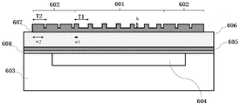
本实施例中的声波带通滤波器单元内的串联谐振器并联谐振器采用图 6所示的薄膜体声波谐振器;该薄膜体声波谐振器包括第一主谐振区域601 和两个第一次谐振区域602组成的声阻抗调谐结构,两个第一次谐振区域 602位于第一主谐振区域601的两侧,其中,第一主谐振区域601具有第一 占空比η1,第一次谐振区域602具有第二占空比η2;声波带通滤波器单元内 的串联谐振频率fs和并联谐振频率fp的改变分别通过调节该第一占空比η1和/或第二占空比η2实现。The series resonator and parallel resonator in the acoustic wave bandpass filter unit in this embodiment adopts the thin film bulk acoustic wave resonator shown in FIG. 6; the thin film bulk acoustic wave resonator includes a first
本申请实施例中,占空比定义为:一个周期内图形区宽度W与周期T (图形区与非图形区总宽度)之间的比值。如图6中所示(图6中所示的 第一次谐振区域602以包括三个第一单元为例),若W2为第一次谐振区域 602中一个单元的图形区宽度(即图6中一个凸起和一个凹陷的总宽度), 第一次谐振区域602中一个单元的周期为T2(即图6中图形区和非图形区 的总宽度),第一次谐振区域602的占空比为W2与周期T2的比值;若W1 为第一主谐振区域601中一个单元的图形宽度,第一主谐振区域601中一 个单元的周期为T1,第一主谐振区域601的占空比为W1与T1的比值。In the embodiment of the present application, the duty cycle is defined as: the ratio between the width W of the pattern area and the period T (the total width of the pattern area and the non-pattern area) in one cycle. As shown in FIG. 6 (the first
图6所示的薄膜体声波谐振器还包括基底603和谐振器堆叠结构;基 底603上与谐振器堆叠结构连接的一面设有反射镜604,反射镜604为空腔 结构或布拉格反射器(DBR);谐振器堆叠结构包括第一电极层605(厚度 0.1μm至0.4μm)、压电薄膜层606(厚度0.5μm至2μm)和第二电极层 607(厚度0.1μm至0.4μm),第一电极层605、压电薄膜层606和第二电 极层607依次层叠连接。The thin film bulk acoustic wave resonator shown in FIG. 6 also includes a
本申请实施例中,基底603可以为高阻硅基底(电阻率1k-100kΩ·cm)、 砷化镓或蓝宝石等;声阻抗调谐结构与第二电极层607可以为相同的金属 材料,也可以为不同金属材料,第二电极层607的金属材料可以为钼(Mo)、 铝(Al)、铂(Pt)、钨(W)、金(Au)等;第一电极层605的材料可以 为钼(Mo)、铝(Al)、铂(Pt)、钨(W)、金(Au)等;压电薄膜层606 可选择为氮化铝(AlN)、氧化锌(ZnO)、锆钛酸铅(PZT)等材料或掺杂 材料,例如,本申请实施例采用的压电薄膜层606为氮化铝(AlN),也可 以是稀土元素(如钪(Sc)等)掺杂的氮化铝AlN。In the embodiment of the present application, the
本申请实施例中,第二电极层607之上可以覆盖一层保护电极被氧化 的钝化层薄膜。In this embodiment of the present application, the
本申请实施例中,谐振器堆叠结构还可以包括种子层或支撑层608;以 支撑层608为例,支撑层608包括相对应的第一面和第二面,支撑层608的 第一面与基底603层叠连接,支撑层608的第二面与第一电极层605层叠 连接。即支撑层608、第一电极层605、压电薄膜层606和第二电极层607 由下至上依次层叠连接。In this embodiment of the present application, the resonator stack structure may further include a seed layer or a
本申请实施例中,声阻抗调谐结构为亚波长声学微结构,所述声学亚波 长可表示为微结构的横向宽度w需要小于纵向声波传播的波长λl,进一步地 可以小于λl/2,纵波波长λl可从谐振器等效膜层厚度计算得到,公式如下:In the embodiment of the present application, the acoustic impedance tuning structure is a subwavelength acoustic microstructure, and the acoustic subwavelength can be expressed as the lateral width w of the microstructure needs to be smaller than the wavelength λl of the longitudinal acoustic wave propagation, and further can be smaller than λl /2, The longitudinal wave wavelength λl can be calculated from the equivalent film thickness of the resonator, and the formula is as follows:

其中,vl为压电薄膜中的纵波声速,tn和vn分别为各膜层厚度及纵波声 速。Among them, vl is the acoustic velocity of longitudinal waves in the piezoelectric film, and tn and vn are the thickness of each film layer and the acoustic velocity of longitudinal waves, respectively.
本申请实施例提供的低插损声波带通滤波器由图6的薄膜体声波谐振 器组成,该薄膜体声波谐振器在第二电极层607上设置声阻抗调谐结构, 该声阻抗调谐结构为亚波长声学微结构;通过调整多个谐振器的第一占空 比η1和/或第二占空比η2可以实现多个谐振器的频率差异调节,将频率点在 通带内进行分散,避免串联谐振频率和并联谐振频率不匹配而引起的损耗 在同一点处叠加;同时,通过调整占空比及周期,可以使得第一主谐振区域 601和第一次谐振区域602的声阻抗不同,不匹配程度提高,能够形成多层 横向声波的反射界面,限制声波能量从谐振器边缘处泄漏,提高谐振器的品 质因数Q值。且该薄膜体声波谐振器的制造方法完全基于成熟的MEMS半导 体工艺技术,可通过现有的设备进行可重复的大批量生产,无需引入其他传 统工艺,大大降低了成本。The low insertion loss acoustic wave bandpass filter provided by the embodiment of the present application is composed of the thin film bulk acoustic wave resonator shown in FIG. 6 . The thin film bulk acoustic wave resonator is provided with an acoustic impedance tuning structure on the
实施例三
请参见图3和图7,本实施例中与实施例二同样采用等间距分布的频率 点,不同的是,本实施例中的薄膜体声波谐振器为图7所示的结构,包括第 二主谐振区域701和两个第二次谐振区域702组成的声阻抗调谐结构,该 两个第二次谐振区域702分别位于第二主谐振区域701的两侧,其中,第 二次谐振区域702包含厚度dx和宽度w的特征;声波带通滤波器单元内的 并联谐振频率fp的改变通过调节厚度d2和/或宽度w实现。Please refer to FIG. 3 and FIG. 7 . In this embodiment, frequency points distributed at equal intervals are also used in the second embodiment. The difference is that the thin film bulk acoustic wave resonator in this embodiment has the structure shown in FIG. An acoustic impedance tuning structure composed of a
图7所示的薄膜体声波谐振器还包括高阻硅基底703(电阻率1k- 100kΩ·cm)以及谐振器堆叠结构,基底703上与谐振器堆叠结构连接的一 面设有反射镜708,反射镜708为空腔结构或布拉格反射器(DBR);谐振 器堆叠结构包括种子层或支撑层704(10nm至50nm)、第一电极层705 (0.1μm至0.4μm)、压电薄膜层706(0.5μm至2μm)以及第一电极层707(0.1μm至0.4μm),第一电极层707之上可以覆盖一层保护电极被 氧化的钝化层薄膜(图中未显示),各层材料与实施例二中图6的相同。The thin-film bulk acoustic wave resonator shown in FIG. 7 also includes a high-resistance silicon substrate 703 (resistivity of 1k-100kΩ·cm) and a resonator stack structure. The side connected to the resonator stack structure on the
在具体实施中,第二次谐振区域702的主要作用是增强横向声波的反 射,避免能量泄漏,提高谐振器的品质因数Q值。根据其等效电路可知,第 二次谐振区域702的结构参数的变化仅改变谐振器的并联谐振频率fp,而 串联谐振频率fs不会发生变化,串联谐振频率fs决定于第二主谐振区域701 的膜层厚度d1。即合理微调并联谐振器的凸起结构参数,包括其厚度d2和 横向宽度w,能够更快地实现串联谐振器和并联谐振器的频率匹配,弥补工艺制备上带来的误差,d1和d2均可以在100nm至800nm范围内取值,w可以 在1μm至100μm范围内取值。第二主谐振区域701的膜层厚度d1一般不 进行调节,因其变化会导致串联谐振频率和并联谐振频率同时改变,频率完 全匹配较难实现。需要说明的是,凸起结构宽度w的调节需要根据横向声 波的色散关系来共同确定,尽量保证为其波长的四分之一,即w=0.25× (2n+1)×λ,其中,n为正整数。In a specific implementation, the main function of the second resonance region 702 is to enhance the reflection of transverse acoustic waves, avoid energy leakage, and improve the quality factor Q value of the resonator. According to its equivalent circuit, the change of the structural parameters of the second resonance region 702 only changes the parallel resonance frequency fp of the resonator, while the series resonance frequency fs does not change. The series resonance frequency fs is determined by the second main resonance frequency f s. The film thickness d1 of the
实施例四
如图4所示,本申请实施例提供了一种低插损声波带通滤波器,包括 五个声波带通滤波器单元,该五个声波带通滤波器单元具有五个不同的匹 配频率f1、f2、f3、f4和f5,如图3所示,f1、f2、f3、f4和f5采用的是渐变 式分布在通带内,频率匹配点由通带中心向两端变化,中心分布较分散,两 端分布较密集,实际的排布规律需要根据滤波器S参数性能进行调整。通 带中心的插入损耗对频率匹配程度较敏感,通常会出现大大小小的凹陷,因 此通带中心的频率点间隔应大于两端频率点间隔。As shown in FIG. 4 , an embodiment of the present application provides a low insertion loss acoustic bandpass filter, including five acoustic bandpass filter units, and the five acoustic bandpass filter units have five different matching frequencies f1 , f2 , f3 , f4 and f5 , as shown in Figure 3, f1 , f2 , f3 , f4 and f5 are gradually distributed in the passband, and the frequency matching point is determined by the passband. The center of the band changes to both ends, the center distribution is more scattered, and the two ends are more densely distributed. The actual arrangement law needs to be adjusted according to the filter S-parameter performance. The insertion loss in the center of the passband is sensitive to the degree of frequency matching, and there are usually large and small depressions. Therefore, the frequency point interval in the center of the passband should be larger than the frequency point interval at both ends.
需要说明的是,本申请实施例的频率点在通带上的划分并不限于上述 实施例二至四中的两种形式,频率匹配点也可以根据滤波器通带纹波进行 优化,将频率点调整至纹谷,可以有效减小通带纹波的抖动幅值,也可以是 其他的划分形式。It should be noted that the division of the frequency points on the passband in the embodiments of the present application is not limited to the two forms in the above-mentioned second to fourth embodiments, and the frequency matching point can also be optimized according to the filter passband ripple, and the frequency Adjusting the point to the valley can effectively reduce the jitter amplitude of the passband ripple, and it can also be other division forms.
图5是本申请实施例的一种可选的梯形结构带通滤波器的频率响应曲 线图,其中菱形曲线为现有技术的带通滤波器,正方形曲线为频率点等间距 分布的带通滤波器,三角形曲线为频率点渐变式分布的带通滤波器。5 is a frequency response curve diagram of an optional trapezoidal structure band-pass filter according to an embodiment of the present application, wherein the diamond-shaped curve is a band-pass filter of the prior art, and the square curve is a band-pass filter with equally spaced frequency points. The triangular curve is a band-pass filter with a gradual distribution of frequency points.
相较于现有技术设计的滤波器,本申请实施例的带通滤波器的通带插 入损耗均能达到减小的有益技术效果,其通带附近的纹波抖动变得更加平 坦。Compared with the filter designed in the prior art, the passband insertion loss of the bandpass filter in the embodiment of the present application can achieve the beneficial technical effect of reducing, and the ripple jitter near the passband becomes flatter.
实施例五
本申请实施例还提供了一种低插损声波带通滤波器的实现方法,包括:Embodiments of the present application also provide a method for implementing a low insertion loss acoustic wave bandpass filter, including:
结合图2、图3和图6所示,利用一个串联谐振器和一个并联谐振器构 成一个声波带通滤波器单元;级联五个声波带通滤波器单元(201,202,203, 204,205);其中,每个声波带通滤波器单元具有一个匹配频率,该级联的 五个声波带通滤波器单元具有五个不同的匹配频率;该声波带通滤波器单 元的匹配频率是由声波带通滤波器单元内的串联谐振频率和并联谐振频率 确定的,且串联谐振频率和并联谐振频率的差值小于等于预设差值。As shown in Fig. 2, Fig. 3 and Fig. 6, a series resonator and a parallel resonator are used to form an acoustic wave bandpass filter unit; five acoustic wave bandpass filter units (201, 202, 203, 204, 205); Wherein, each acoustic wave bandpass filter unit has a matching frequency, and five acoustic wave bandpass filter units of this cascade have five different matching frequencies; The matching frequency of this acoustic wavebandpass filter unit is by The series resonance frequency and the parallel resonance frequency in the acoustic wave bandpass filter unit are determined, and the difference between the series resonance frequency and the parallel resonance frequency is less than or equal to a preset difference.
其中,并联谐振器的第一端接地,并联谐振器的第二端连接串联谐振器 的任一端,形成一个声波带通滤波器单元,多个声波带通滤波器单元中的每 个声波带通滤波器单元的连接方式是一致的。The first end of the parallel resonator is grounded, and the second end of the parallel resonator is connected to either end of the series resonator to form an acoustic wave bandpass filter unit, and each acoustic wave bandpass filter unit in the plurality of acoustic wave bandpass filter units The filter units are connected in the same way.
该声波带通滤波器单元内的串联谐振器和并联谐振器采用薄膜体声波 谐振器;该薄膜体声波谐振器包括第一主谐振区域601和第一次谐振区域 602,第一主谐振区域601具有第一占空比η1,第一次谐振区域602具有第 二占空比η2;声波带通滤波器单元内的串联谐振频率fs和并联谐振频率fp的 改变分别通过调节第一占空比η1和/或第二占空比η2实现。The series resonators and parallel resonators in the acoustic bandpass filter unit are thin-film bulk acoustic resonators; the thin-film bulk acoustic resonators include a first
具体地,声波带通滤波器单元内的串联谐振频率fs和并联谐振频率fp的 改变分别通过调节第一占空比η1和/或第二占空比η2实现,包括:Specifically, the change of the series resonant frequency fs and the parallel resonant frequency fp in the acoustic wave bandpass filter unit is respectively realized by adjusting the first duty cycle η1 and/or the second duty cycle η2 , including:
若级联的多个声波带通滤波器单元具有五个匹配频率f1、f2、f3、f4和 f5,且该五个匹配频率依次相差13MHz(等间距分布),串联谐振频率fs对 第一占空比η1变化量的平均值为13MHz/0.1;则确定f1、f2、f3、f4和f5对 应的串联谐振器的第一占空比


实施例六Embodiment 6
本申请实施例还提供了一种低插损声波带通滤波器的实现方法,包括:Embodiments of the present application also provide a method for implementing a low insertion loss acoustic wave bandpass filter, including:
结合图2、图3和图7所示,利用一个串联谐振器和一个并联谐振器构 成一个声波带通滤波器单元;级联五个声波带通滤波器单元(201,202,203, 204,205);其中,每个声波带通滤波器单元具有一个匹配频率,该级联的 五个声波带通滤波器单元具有五个不同的匹配频率;该声波带通滤波器单 元的匹配频率是由声波带通滤波器单元内的串联谐振频率和并联谐振频率 确定的,且串联谐振频率和并联谐振频率的差值小于等于预设差值。As shown in Fig. 2, Fig. 3 and Fig. 7, a series resonator and a parallel resonator are used to form an acoustic wave bandpass filter unit; five acoustic wave bandpass filter units (201, 202, 203, 204, 205); Wherein, each acoustic wave bandpass filter unit has a matching frequency, and five acoustic wave bandpass filter units of this cascade have five different matching frequencies; The matching frequency of this acoustic wavebandpass filter unit is by The series resonance frequency and the parallel resonance frequency in the acoustic wave bandpass filter unit are determined, and the difference between the series resonance frequency and the parallel resonance frequency is less than or equal to a preset difference.
其中,并联谐振器的第一端接地,并联谐振器的第二端连接串联谐振器 的任一端,形成一个声波带通滤波器单元,多个声波带通滤波器单元中的每 个声波带通滤波器单元的连接方式是一致的。The first end of the parallel resonator is grounded, and the second end of the parallel resonator is connected to either end of the series resonator to form an acoustic wave bandpass filter unit, and each acoustic wave bandpass filter unit in the plurality of acoustic wave bandpass filter units The filter units are connected in the same way.
该声波带通滤波器单元内的串联谐振器和并联谐振器采用薄膜体声波 谐振器;该薄膜体声波谐振器包括第二主谐振区域701和第二次谐振区域 702,第二次谐振区域702包含厚度d2和宽度w的特征;该声波带通滤波器 单元内的并联谐振频率fp的改变通过调节厚度d2和/或宽度w实现。The series resonators and parallel resonators in the acoustic bandpass filter unit are thin-film bulk acoustic resonators; the thin-film bulk acoustic resonators include a second
具体地,声波带通滤波器单元内的并联谐振频率fp的改变通过调节厚度 d2和/或宽度w实现,包括:Specifically, the change of the parallel resonance frequency fp in the acoustic wave bandpass filter unit is realized by adjusting the thickness d2 and/or the width w, including:
若级联的多个声波带通滤波器单元具有五个匹配频率f1、f2、f3、f4和 f5,且所述五个匹配频率依次相差13MHz(等间距分布),并联谐振频率fp对有效面积A变化量的平均值为3.33MHz/1000μm2,其中,有效面积A为 所述厚度d2和所述宽度w的乘积;则确定f1、f2、f3、f4和f5对应的并联谐 振器的有效面积A201、A202、A203、A204和A205分别为700μm2、4600μm2、8500μm2、 12400μm2和16300μm2;预设厚度d2为500nm,根据有效面积A201、A202、A203、 A204和A205分别确定对应的w201、w202、w203、w204和w205;基于确定的w201、w202、 w203、w204和w205,调整光刻板中对应的图形区域,通过一次刻蚀实现多个所 述并联谐振频率的差异调节。If the cascaded multiple acoustic wave bandpass filter units have five matching frequencies f1 , f2 , f3 , f4 and f5 , and the five matching frequencies differ in sequence by 13 MHz (distributed at equal intervals), the parallel resonance The average value of the variation of the frequency fp to the effective area A is 3.33MHz/1000μm2 , where the effective area A is the product of the thickness d2 and the width w; then determine f1 , f2 , f3 , f The effective areas A201 , A202 , A203 , A204 and A205 of the parallel resonators corresponding to4 and f5 are respectively 700 μm2 , 4600
在具体实施中,第二次谐振区域702的主要作用是增强横向声波的反 射,避免能量泄漏,提高谐振器的品质因数Q值。根据其等效电路可知,第 二次谐振区域702的结构参数的变化仅改变谐振器的并联谐振频率fp,而 串联谐振频率fs不会发生变化,串联谐振频率fs决定于第二主谐振区域701 的膜层厚度d1。即合理微调并联谐振器的凸起结构参数,包括其厚度d2和 横向宽度w,能够更快地实现串联谐振器和并联谐振器的频率匹配,弥补工艺制备上带来的误差,d1和d2均可以在100nm至800nm范围内取值,w可以 在1μm至100μm范围内取值。第二主谐振区域701的膜层厚度d1一般不 进行调节,因其变化会导致串联谐振频率和并联谐振频率同时改变,频率完 全匹配较难实现。需要说明的是,凸起结构宽度w的调节需要根据横向声 波的色散关系来共同确定,尽量保证为其波长的四分之一,即w=0.25× (2n+1)×λ,其中,n为正整数。In a specific implementation, the main function of the second resonance region 702 is to enhance the reflection of transverse acoustic waves, avoid energy leakage, and improve the quality factor Q value of the resonator. According to its equivalent circuit, the change of the structural parameters of the second resonance region 702 only changes the parallel resonance frequency fp of the resonator, while the series resonance frequency fs does not change. The series resonance frequency fs is determined by the second main resonance frequency f s. The film thickness d1 of the
d1和d2均可在100nm至800nm范围内取值,w可以在1μm至100μm范 围内取值,此时,若并联谐振器的有效面积A201、A202、A203、A204和A205分别 确定为700μm2、4600μm2、8500μm2、12400μm2和16300μm2,由n取值不 同而不同,根据有效面积A合理调整横向宽度w和谐振器总面积S即可。 具体地,其中,图2中的并联谐振器201-2的宽度w201可以是3.5μm,总面 积S201为18700μm2;d1-201厚度可以是223.7nm;d2-201厚度可以是500nm。并 联谐振器202-2、203-2、204-2、205-2类似,需要根据滤波器的工作频率 进行调整。Both d1 and d2 can take values in the range of 100 nm to 800 nm, and w can take values in therange of 1μm to100μm .205 is determined to be 700 μm2 , 4600 μm2 , 8500 μm2 , 12400 μm2 and 16300 μm2 respectively, which are different depending on the value of n, and the lateral width w and the total area S of the resonator can be reasonably adjusted according to the effective area A. Specifically, the width w201 of the parallel resonator 201-2 in FIG. 2 may be 3.5 μm, the total area S201 may be 18700 μm2 ; the thickness of d1-201 may be 223.7 nm; the thickness of d2-201 may be 500 nm . The parallel resonators 202-2, 203-2, 204-2, and 205-2 are similar and need to be adjusted according to the operating frequency of the filter.
实施例七Embodiment 7
本申请实施例的低插损声波带通滤波器的实现方法中,串联谐振器和 并联谐振器的组合不仅可以采用上述的实施例中的方式,也可以是如图 8~10所示的组合方式,其中图8对应4个匹配频率,图9对应3个匹配频 率,图10对应两个匹配频率,即谐振器A的组合、谐振器B的组合、谐振 器C的组合、谐振器D的组合分别对应一个匹配频率,且每个组合内至少 包含一个串联谐振器和一个并联谐振器,其串联谐振频率和并联谐振频率 需要严格按照频率点匹配,匹配方法均可以运用上述实施例五和实施例六 中的方法对串联谐振频率和并联谐振频率进行微调,实现匹配。In the implementation method of the low-insertion-loss acoustic band-pass filter according to the embodiment of the present application, the combination of the series resonator and the parallel resonator can not only adopt the method in the above-mentioned embodiment, but also can be the combination shown in FIGS. 8 to 10 . Figure 8 corresponds to 4 matching frequencies, Figure 9 corresponds to 3 matching frequencies, and Figure 10 corresponds to two matching frequencies, namely the combination of resonator A, the combination of resonator B, the combination of resonator C, the combination of resonator D The combination corresponds to a matching frequency, and each combination contains at least one series resonator and one parallel resonator. The series resonant frequency and the parallel resonant frequency need to be matched strictly according to the frequency point, and the matching method can be applied to the above-mentioned
需要说明的是,图8仅对谐振器的组合方式做说明性示意,并非 完全按照图示进行组合,即相同频率组合之间还可以存在其他频率的 组合;图示中的A、B、C、D标注仅作为谐振器的归类,前后相同标 注的谐振器并不代表有结构参数或频率上的一致性。另外,频率匹配 点个数也不局限于2-4个,根据实际滤波器的通带性能不同而不同。 合理设计谐振器的频率匹配点个数、通带位置以及谐振器的组合方式, 分散频率匹配点,避免由谐振频率不匹配引起的损耗叠加,能够使滤 波器具有更好的通带插损特性。It should be noted that FIG. 8 only illustrates the combination of the resonators, not completely according to the diagram, that is, there may be other frequency combinations between the same frequency combination; A, B, C in the diagram , D labels are only used as the classification of resonators, and resonators with the same label before and after do not represent the consistency of structural parameters or frequency. In addition, the number of frequency matching points is not limited to 2-4, and it varies according to the passband performance of the actual filter. Reasonable design of the number of resonator frequency matching points, passband position and combination of resonators, dispersing the frequency matching points, avoiding the superposition of losses caused by the mismatch of the resonant frequency, can make the filter have better passband insertion loss characteristics .
需要说明的是,本申请实施例的低插损声波带通滤波器及其实现方法 不仅应用于上述的薄膜体声波滤波器(FBAR)中,也能够在固态装配型谐振 器(SMR)、声表面波谐振器(SAW)或其他具有类似原理谐振器中的应用。It should be noted that the low-insertion-loss acoustic band-pass filter and the implementation method thereof in the embodiments of the present application are not only applied to the above-mentioned thin-film bulk acoustic wave filter (FBAR), but also can be used in solid-state assembled resonators (SMR), acoustic Surface wave resonators (SAW) or other resonators with similar principles.
以上所述是本发明的优选实施方式,应当指出,对于本技术领域的普通 技术人员来说,在不脱离本发明原理的前提下,还可以做出若干改进和润饰, 这些改进和润饰也视为本发明的保护范围。The above are the preferred embodiments of the present invention. It should be pointed out that for those skilled in the art, without departing from the principles of the present invention, several improvements and modifications can be made, and these improvements and modifications may also be regarded as It is the protection scope of the present invention.
Claims (10)
Translated fromChinese


Priority Applications (1)
| Application Number | Priority Date | Filing Date | Title |
|---|---|---|---|
| CN202110024640.6ACN114759899A (en) | 2021-01-08 | 2021-01-08 | Low-insertion-loss acoustic wave band-pass filter and implementation method thereof |
Applications Claiming Priority (1)
| Application Number | Priority Date | Filing Date | Title |
|---|---|---|---|
| CN202110024640.6ACN114759899A (en) | 2021-01-08 | 2021-01-08 | Low-insertion-loss acoustic wave band-pass filter and implementation method thereof |
Publications (1)
| Publication Number | Publication Date |
|---|---|
| CN114759899Atrue CN114759899A (en) | 2022-07-15 |
Family
ID=82325263
Family Applications (1)
| Application Number | Title | Priority Date | Filing Date |
|---|---|---|---|
| CN202110024640.6APendingCN114759899A (en) | 2021-01-08 | 2021-01-08 | Low-insertion-loss acoustic wave band-pass filter and implementation method thereof |
Country Status (1)
| Country | Link |
|---|---|
| CN (1) | CN114759899A (en) |
Cited By (2)
| Publication number | Priority date | Publication date | Assignee | Title |
|---|---|---|---|---|
| CN116169452A (en)* | 2022-12-15 | 2023-05-26 | 北京芯溪半导体科技有限公司 | Filter design method and device and related equipment |
| CN117040477A (en)* | 2022-12-16 | 2023-11-10 | 北京芯溪半导体科技有限公司 | Filter, multiplexer and communication equipment |
Citations (10)
| Publication number | Priority date | Publication date | Assignee | Title |
|---|---|---|---|---|
| CN1383611A (en)* | 2000-06-16 | 2002-12-04 | 皇家菲利浦电子有限公司 | Bulk accoustic wave filter |
| CN1951005A (en)* | 2004-05-07 | 2007-04-18 | 英特尔公司 | Forming integrated plural frequency band film bulk acoustic resonators |
| US20070247259A1 (en)* | 2004-12-24 | 2007-10-25 | Murata Manufacturing Co., Ltd. | Branching filter |
| US20110316648A1 (en)* | 2009-03-10 | 2011-12-29 | Murata Manufacturing Co., Ltd. | Elastic-wave ladder filter |
| CN103929148A (en)* | 2013-01-11 | 2014-07-16 | 中兴通讯股份有限公司 | A low insertion loss piezoelectric acoustic wave bandpass filter and its realization method |
| CN107623504A (en)* | 2016-07-15 | 2018-01-23 | 株式会社村田制作所 | Multiplexer, high-frequency front-end circuit and communicator |
| CN108449068A (en)* | 2018-01-31 | 2018-08-24 | 湖北宙讯科技有限公司 | Duplexer |
| CN109889179A (en)* | 2018-12-26 | 2019-06-14 | 天津大学 | Resonators and Ladder Filters |
| US20190222195A1 (en)* | 2018-01-12 | 2019-07-18 | Taiyo Yuden Co., Ltd. | Acoustic wave resonator, filter, and multiplexer |
| CN111355464A (en)* | 2018-12-20 | 2020-06-30 | 天津大学 | Device for adjusting effective electromechanical coupling coefficient based on annular protrusion |
- 2021
- 2021-01-08CNCN202110024640.6Apatent/CN114759899A/enactivePending
Patent Citations (10)
| Publication number | Priority date | Publication date | Assignee | Title |
|---|---|---|---|---|
| CN1383611A (en)* | 2000-06-16 | 2002-12-04 | 皇家菲利浦电子有限公司 | Bulk accoustic wave filter |
| CN1951005A (en)* | 2004-05-07 | 2007-04-18 | 英特尔公司 | Forming integrated plural frequency band film bulk acoustic resonators |
| US20070247259A1 (en)* | 2004-12-24 | 2007-10-25 | Murata Manufacturing Co., Ltd. | Branching filter |
| US20110316648A1 (en)* | 2009-03-10 | 2011-12-29 | Murata Manufacturing Co., Ltd. | Elastic-wave ladder filter |
| CN103929148A (en)* | 2013-01-11 | 2014-07-16 | 中兴通讯股份有限公司 | A low insertion loss piezoelectric acoustic wave bandpass filter and its realization method |
| CN107623504A (en)* | 2016-07-15 | 2018-01-23 | 株式会社村田制作所 | Multiplexer, high-frequency front-end circuit and communicator |
| US20190222195A1 (en)* | 2018-01-12 | 2019-07-18 | Taiyo Yuden Co., Ltd. | Acoustic wave resonator, filter, and multiplexer |
| CN108449068A (en)* | 2018-01-31 | 2018-08-24 | 湖北宙讯科技有限公司 | Duplexer |
| CN111355464A (en)* | 2018-12-20 | 2020-06-30 | 天津大学 | Device for adjusting effective electromechanical coupling coefficient based on annular protrusion |
| CN109889179A (en)* | 2018-12-26 | 2019-06-14 | 天津大学 | Resonators and Ladder Filters |
Non-Patent Citations (2)
| Title |
|---|
| YOOK-KONG YONG: "Nonlinear frequency response of second harmonic generation in SAW IDT resonators", 2017 IEEE INTERNATIONAL ULTRASONICS SYMPOSIUM (IUS)》, 2 November 2017 (2017-11-02)* |
| 陈尚权: "一种基于WLP封装的声表面波滤波器", 《 压电与声光》, 20 August 2020 (2020-08-20)* |
Cited By (4)
| Publication number | Priority date | Publication date | Assignee | Title |
|---|---|---|---|---|
| CN116169452A (en)* | 2022-12-15 | 2023-05-26 | 北京芯溪半导体科技有限公司 | Filter design method and device and related equipment |
| CN116169452B (en)* | 2022-12-15 | 2023-09-22 | 北京芯溪半导体科技有限公司 | Filter design method and device and related equipment |
| CN117040477A (en)* | 2022-12-16 | 2023-11-10 | 北京芯溪半导体科技有限公司 | Filter, multiplexer and communication equipment |
| CN117040477B (en)* | 2022-12-16 | 2024-01-23 | 北京芯溪半导体科技有限公司 | Filter, multiplexer and communication equipment |
Similar Documents
| Publication | Publication Date | Title |
|---|---|---|
| TWI734153B (en) | Resonant cavity surface acoustic wave (saw) filters | |
| CN105897211B (en) | Film bulk acoustic resonator with multiple resonant modes, preparation method thereof and filter | |
| CN100586010C (en) | Bulk Acoustic Wave Filter and Method of Eliminating Unnecessary Side Pass Bands | |
| US7170370B2 (en) | Filter device capable of obtaining attenuation characteristic of sharpness in narrow band width and branching filter using the same | |
| JP2004158970A (en) | Bandpass filter using thin film piezoelectric resonator | |
| US20050127794A1 (en) | Surface acoustic wave device and manufacturing method thereof | |
| JP4836748B2 (en) | Bulk acoustic wave resonator, filter device, and communication device | |
| CN114257206B (en) | Surface Acoustic Wave Resonators, Filters and Communication Devices | |
| CN113541636B (en) | Acoustic wave resonator and preparation method thereof | |
| US20100109809A1 (en) | Thin film piezoelectric resonator and thin film piezoelectric filter | |
| CN114759899A (en) | Low-insertion-loss acoustic wave band-pass filter and implementation method thereof | |
| WO2024207825A1 (en) | Lamb wave resonator and filter | |
| CN111953314B (en) | Filter design method and filter, multiplexer, communication equipment | |
| CN116458060A (en) | Piezoelectric layer arrangement in an acoustic wave device and related methods | |
| CN117121381A (en) | Tiled, laterally excited thin film bulk acoustic resonator high power filter | |
| US7075214B2 (en) | Piezoelectric resonator and electronic component provided therewith | |
| JP2003534696A (en) | Filter improvements | |
| CN117879534A (en) | A bridge-type bulk acoustic wave resonator, manufacturing method and communication device | |
| CN117767906A (en) | Transverse excitation lamb wave resonator and manufacturing method thereof | |
| CN118074652A (en) | Electrode structure, bulk acoustic wave resonator structure and filter | |
| CN111817687B (en) | Filter design method, filter, multiplexer and communication equipment | |
| CN109889173B (en) | Connection structure of flexible substrate thin-film bulk acoustic wave filter | |
| Pensala et al. | Laterally acoustically coupled BAW filters at 3.6 GHz | |
| CN116671013A (en) | Filter and manufacturing method of filter | |
| CN116248072B (en) | Acoustic wave filter and signal processing circuit |
Legal Events
| Date | Code | Title | Description |
|---|---|---|---|
| PB01 | Publication | ||
| PB01 | Publication | ||
| SE01 | Entry into force of request for substantive examination | ||
| SE01 | Entry into force of request for substantive examination |