CN114754967A - Wind tunnel comprehensive test platform for supersonic flow field aero-optic effect - Google Patents
Wind tunnel comprehensive test platform for supersonic flow field aero-optic effectDownload PDFInfo
- Publication number
- CN114754967A CN114754967ACN202210291259.0ACN202210291259ACN114754967ACN 114754967 ACN114754967 ACN 114754967ACN 202210291259 ACN202210291259 ACN 202210291259ACN 114754967 ACN114754967 ACN 114754967A
- Authority
- CN
- China
- Prior art keywords
- wind tunnel
- optical
- supersonic
- flow field
- test
- Prior art date
- Legal status (The legal status is an assumption and is not a legal conclusion. Google has not performed a legal analysis and makes no representation as to the accuracy of the status listed.)
- Granted
Links
- 238000012360testing methodMethods0.000titleclaimsabstractdescription111
- 230000000694effectsEffects0.000titledescription41
- 230000003287optical effectEffects0.000claimsabstractdescription64
- 230000005540biological transmissionEffects0.000claimsabstractdescription14
- 238000000926separation methodMethods0.000claimsabstract23
- 238000002474experimental methodMethods0.000claimsabstract3
- 238000007789sealingMethods0.000claimsdescription23
- 239000005304optical glassSubstances0.000claimsdescription22
- 238000001514detection methodMethods0.000claimsdescription17
- 239000011521glassSubstances0.000claimsdescription15
- 239000002245particleSubstances0.000claimsdescription11
- 230000001360synchronised effectEffects0.000claimsdescription11
- 238000009434installationMethods0.000claimsdescription10
- 238000001914filtrationMethods0.000claimsdescription6
- 239000000700radioactive tracerSubstances0.000claimsdescription6
- 238000001816coolingMethods0.000claimsdescription4
- 230000007613environmental effectEffects0.000claimsdescription2
- 239000007921spraySubstances0.000claims4
- 230000002035prolonged effectEffects0.000claims1
- 230000007246mechanismEffects0.000abstractdescription6
- 230000009286beneficial effectEffects0.000abstractdescription4
- 238000005259measurementMethods0.000abstractdescription2
- 239000007789gasSubstances0.000description23
- 238000010586diagramMethods0.000description7
- 239000000112cooling gasSubstances0.000description6
- 238000013461designMethods0.000description5
- 238000012545processingMethods0.000description4
- 238000005516engineering processMethods0.000description2
- 238000000034methodMethods0.000description2
- 238000012986modificationMethods0.000description2
- 230000004048modificationEffects0.000description2
- 230000009467reductionEffects0.000description2
- 238000010998test methodMethods0.000description2
- 230000004888barrier functionEffects0.000description1
- 230000015572biosynthetic processEffects0.000description1
- 230000008859changeEffects0.000description1
- 238000004891communicationMethods0.000description1
- 238000012937correctionMethods0.000description1
- 238000004880explosionMethods0.000description1
- 238000012812general testMethods0.000description1
- 230000006872improvementEffects0.000description1
- 239000012528membraneSubstances0.000description1
- 238000011160researchMethods0.000description1
- 238000005507sprayingMethods0.000description1
- 230000007704transitionEffects0.000description1
Images


Classifications
- G—PHYSICS
- G01—MEASURING; TESTING
- G01M—TESTING STATIC OR DYNAMIC BALANCE OF MACHINES OR STRUCTURES; TESTING OF STRUCTURES OR APPARATUS, NOT OTHERWISE PROVIDED FOR
- G01M9/00—Aerodynamic testing; Arrangements in or on wind tunnels
- G01M9/02—Wind tunnels
- G—PHYSICS
- G01—MEASURING; TESTING
- G01M—TESTING STATIC OR DYNAMIC BALANCE OF MACHINES OR STRUCTURES; TESTING OF STRUCTURES OR APPARATUS, NOT OTHERWISE PROVIDED FOR
- G01M9/00—Aerodynamic testing; Arrangements in or on wind tunnels
- G01M9/02—Wind tunnels
- G01M9/04—Details
- G—PHYSICS
- G01—MEASURING; TESTING
- G01M—TESTING STATIC OR DYNAMIC BALANCE OF MACHINES OR STRUCTURES; TESTING OF STRUCTURES OR APPARATUS, NOT OTHERWISE PROVIDED FOR
- G01M9/00—Aerodynamic testing; Arrangements in or on wind tunnels
- G01M9/06—Measuring arrangements specially adapted for aerodynamic testing
- G—PHYSICS
- G01—MEASURING; TESTING
- G01M—TESTING STATIC OR DYNAMIC BALANCE OF MACHINES OR STRUCTURES; TESTING OF STRUCTURES OR APPARATUS, NOT OTHERWISE PROVIDED FOR
- G01M9/00—Aerodynamic testing; Arrangements in or on wind tunnels
- G01M9/08—Aerodynamic models
Landscapes
- Physics & Mathematics (AREA)
- Fluid Mechanics (AREA)
- General Physics & Mathematics (AREA)
- Aerodynamic Tests, Hydrodynamic Tests, Wind Tunnels, And Water Tanks (AREA)
Abstract
Description
Translated fromChinese技术领域technical field
本发明涉及超声速流场实验装置技术领域,特别地,涉及一种超声速流场气动光学效应风洞综合测试平台。The invention relates to the technical field of supersonic flow field experimental devices, in particular to a wind tunnel comprehensive test platform for supersonic flow field aero-optical effects.
背景技术Background technique
现有的超声速流场气动光学效应风洞测试装置主要是使用波前传感器记录光束穿过流场后的畸变波前信息,其中,波前传感器可以是哈特曼波前传感器或者剪切干涉仪波前传感器,然后基于畸变波前信息,研究人员可以评估流场气动光学效应的强弱和分布特性,进而为气动光学效应研究和校正提供依据。Existing wind tunnel testing devices for aero-optical effects of supersonic flow fields mainly use wavefront sensors to record the distorted wavefront information after the beam passes through the flow field. The wavefront sensor can be a Hartmann wavefront sensor or a shear interferometer. The wavefront sensor, and then based on the distorted wavefront information, researchers can evaluate the strength and distribution characteristics of the aero-optical effect of the flow field, and then provide a basis for the research and correction of the aero-optical effect.
但是,由于波前传感器受自身传感器性能限制,一般测试的帧频比较低,无法进行高频帧(Malley Probe,MP技术)光束抖动信息的获取。即无法进行MP测试。另外,也没有同步采集相应的流场参数信息,无法从流动机理本身出发研究气动光学效应相关规律的物理内涵。因此,现有的超声速流场气动光学效应风洞测试装置只能进行波前测试这一单一测试手段,而无法采集流场参数信息和MP测试所需信息,无法深入分析气动光学效应内在的流动机理。However, because the wavefront sensor is limited by its own sensor performance, the frame rate of the general test is relatively low, and the beam jitter information of the high-frequency frame (Malley Probe, MP technology) cannot be obtained. That is, the MP test cannot be performed. In addition, there is no synchronous acquisition of the corresponding flow field parameter information, and it is impossible to study the physical connotation of the relevant laws of aero-optical effects from the flow mechanism itself. Therefore, the existing wind tunnel testing device for aero-optical effect of supersonic flow field can only perform a single test method of wavefront test, but cannot collect flow field parameter information and information required for MP test, and cannot deeply analyze the inherent flow of aero-optical effect. mechanism.
发明内容SUMMARY OF THE INVENTION
本发明提供了一种超声速流场气动光学效应风洞综合测试平台,以解决现有的超声速流场气动光学效应风洞测试装置只能进行波前测试这一单一测试手段,而无法采集流场参数信息和MP测试所需信息,无法深入分析气动光学效应内在的流动机理的技术问题。The invention provides a wind tunnel comprehensive test platform for supersonic flow field aero-optical effect, so as to solve the problem that the existing supersonic flow field aero-optical effect wind tunnel test device can only perform a single test method of wavefront test, but cannot collect flow field The parametric information and the information required for the MP test cannot deeply analyze the technical problems of the inherent flow mechanism of the aero-optical effect.
根据本发明的一个方面,提供一种超声速流场气动光学效应风洞综合测试平台,包括第一隔腔、第二隔腔、激光光源、激光器、半透半反镜、波前探测装置、第一位置探测器、光阑和CCD相机,所述第一隔腔密封安装在风洞设备实验段的上侧板上,所述第二隔腔密封安装在风洞设备实验段的下侧板上,且所述第一隔腔和第二隔腔相对设置,所述激光光源位于所述第二隔腔的外侧,用于发出连续激光,所述光阑设置在所述第二隔腔内并位于连续激光的传输路径上,用于调节光学孔径的大小,所述半透半反镜位于所述第一隔腔的外侧,用于将穿过第二隔腔和第一隔腔后的连续激光分为两条传输光路,所述第一位置探测器和波前探测装置分别位于两条光路上,所述第一位置探测器用于获取MP测试所需的信息,所述波前探测装置用于获取波前测试所需的信息,所述激光器位于所述第一隔腔的外侧,用于发出激光脉冲,CCD相机位于所述第二隔腔的外侧,用于拍摄超声速气流中示踪粒子的粒子图像并获取NPLS测试和PIV测试所需的信息。According to one aspect of the present invention, there is provided a wind tunnel comprehensive test platform for supersonic flow field aero-optical effects, including a first compartment, a second compartment, a laser light source, a laser, a half mirror, a wavefront detection device, a A position detector, diaphragm and CCD camera, the first compartment is sealed and installed on the upper side plate of the experimental section of the wind tunnel equipment, and the second compartment is sealed and installed on the lower side plate of the experimental section of the wind tunnel equipment , and the first compartment and the second compartment are oppositely arranged, the laser light source is located outside the second compartment, and is used to emit continuous laser light, and the diaphragm is arranged in the second compartment and It is located on the transmission path of the continuous laser and is used to adjust the size of the optical aperture. The semi-transparent mirror is located outside the first The laser is divided into two transmission optical paths, the first position detector and the wavefront detection device are respectively located on the two optical paths, the first position detector is used to obtain the information required for the MP test, and the wavefront detection device is used for In order to obtain the information required for the wavefront test, the laser is located outside the first compartment for emitting laser pulses, and the CCD camera is located outside the second compartment for photographing tracer particles in the supersonic airflow particle images and obtain the information needed for NPLS testing and PIV testing.
进一步地,还包括多通道高精度同步控制器,所述多通道高精度同步控制器分别与CCD相机、波前探测装置、第一位置探测器和风洞的压力传感器连接,在进行测试时,所述多通道高精度同步控制器利用风洞的压力传感器检测到风洞开始运行时的压力跃升信号作为同步控制触发信号,并延长预设时间后控制CCD相机、波前探测装置、第一位置探测器进行同步采集。Further, a multi-channel high-precision synchronization controller is also included, and the multi-channel high-precision synchronization controller is respectively connected with the CCD camera, the wavefront detection device, the first position detector and the pressure sensor of the wind tunnel. The multi-channel high-precision synchronous controller uses the pressure sensor of the wind tunnel to detect the pressure jump signal when the wind tunnel starts to operate as a synchronous control trigger signal, and extends the preset time to control the CCD camera, the wavefront detection device, the first position The detectors are acquired synchronously.
进一步地,所述激光器发出的激光脉冲波长为532nm,所述激光光源发出的连续激光波长为632.8nm,所述CCD相机的镜头前方安装有包含632.8nm波段的陷波滤光片,用于消除连续激光对NPLS测试和PIV测试的干扰。Further, the wavelength of the laser pulse emitted by the laser is 532 nm, the wavelength of the continuous laser emitted by the laser light source is 632.8 nm, and a notch filter including a 632.8 nm band is installed in front of the lens of the CCD camera to eliminate CW laser interference with NPLS testing and PIV testing.
进一步地,所述激光光源和光阑之间还设置有用于缩束和滤波的空间滤波器。Further, a spatial filter for beam reduction and filtering is also arranged between the laser light source and the diaphragm.
进一步地,还包括用于记录环境及测试系统噪声的第二位置探测器,为后期对第一位置探测器的记录数据进行数据噪声滤除提供依据。Further, it also includes a second position detector for recording the noise of the environment and the test system, which provides a basis for performing data noise filtering on the recorded data of the first position detector in the later stage.
进一步地,所述第一隔腔包括实验模型、立刀、光学隔腔和光学玻璃,所述光学隔腔的顶部密封安装在风洞实验段的上侧板上,所述立刀安装在所述风洞实验段的上侧板上并位于所述光学隔腔的前方,所述实验模型密封安装在所述立刀和光学隔腔的底部,所述实验模型上开设有玻璃安装孔,所述光学玻璃密封安装在所述玻璃安装孔内。Further, the first compartment includes an experimental model, a vertical knife, an optical compartment and an optical glass, the top of the optical compartment is sealed and installed on the upper side plate of the experimental section of the wind tunnel, and the vertical knife is installed on the The upper side plate of the experimental section of the wind tunnel is located in front of the optical compartment, the experimental model is sealed and installed on the bottom of the vertical knife and the optical compartment, and the experimental model is provided with a glass installation hole, so The optical glass is sealed and mounted in the glass mounting hole.
进一步地,所述立刀的前缘夹角为15°~30°。Further, the included angle of the leading edge of the vertical knife is 15°˜30°.
进一步地,所述光学玻璃带有台阶,所述实验模型上的玻璃安装孔为台阶孔,所述光学玻璃的台阶面与所述玻璃安装孔的台阶面之间设置有第一密封圈,所述光学玻璃的顶面与所述光学隔腔的底面之间设置有第二密封圈。Further, the optical glass has steps, the glass mounting holes on the experimental model are stepped holes, and a first sealing ring is arranged between the stepped surface of the optical glass and the stepped surface of the glass mounting hole, so A second sealing ring is arranged between the top surface of the optical glass and the bottom surface of the optical compartment.
进一步地,所述光学隔腔的顶面与风洞实验段的上侧板之间设置有第三密封圈,所述光学隔腔的底面与所述实验模型之间设置有第四密封圈。Further, a third sealing ring is arranged between the top surface of the optical compartment and the upper side plate of the wind tunnel experimental section, and a fourth sealing ring is arranged between the bottom surface of the optical compartment and the experimental model.
进一步地,所述实验模型为超声速气膜实验板,所述超声速气膜实验板包括带后台阶的实验板、超声速气膜形成喷管和超声速气膜供气管路,所述带后台阶的实验板密封安装在所述光学隔腔和立刀上,所述超声速气膜形成喷管可拆卸地密封安装在所述带后台阶的实验板上,所述超声速气膜供气管路安装在所述带后台阶的实验板上,所述超声速气膜供气管路分别与外部气源、所述超声速气膜形成喷管连通,用于为超声速气膜形成喷管提供冷却气体。Further, the experimental model is a supersonic air film experimental board, and the supersonic air film experimental board includes an experimental board with a back step, a supersonic air film forming nozzle and a supersonic air film air supply pipeline. The plate is sealed and installed on the optical compartment and the vertical knife, the supersonic air film forming nozzle is detachably sealed and installed on the experimental board with the rear step, and the supersonic air film air supply pipeline is installed on the On the experimental board with the rear step, the supersonic gas film gas supply pipeline is respectively connected with an external gas source and the supersonic gas film forming nozzle, and is used for providing cooling gas for the supersonic gas film forming nozzle.
本发明具有以下效果:The present invention has the following effects:
本发明的超声速流场气动光学效应风洞综合测试平台,在同一风洞运行车次下可以同时进行波前测试、MP测试、NPLS测试和PIV测试,单次测量获取的信息量大,有效节约了风洞运行车次,降低了实验成本,并且可以同步获取流场参数信息和气动光学效应相关参数,有助于分析气动光学效应内在的流动机理。并且,利用半透半反镜可以获取相同区域内不同类型的气动光学效应信息,有利于提高气动光学效应测试的准确性和可靠性。另外,还通过在测试区域上方设置密封安装的第一隔腔,可以消除风洞上壁面湍流边界层的影响,通过在测试区域下方设置密封安装的第二隔腔,可以消除风洞下壁面湍流边界层的影响,从而保证风洞上下壁面湍流边界层不会对光线传输产生干扰,大大提升了气动光学效应测试的准确性。The wind tunnel comprehensive test platform of the supersonic flow field aero-optical effect of the present invention can conduct wavefront test, MP test, NPLS test and PIV test at the same time under the same wind tunnel operation. The number of trips in the wind tunnel reduces the experimental cost, and can simultaneously obtain the flow field parameter information and the related parameters of the aero-optical effect, which is helpful to analyze the inherent flow mechanism of the aero-optical effect. In addition, different types of aero-optical effect information in the same area can be obtained by using the semi-transparent mirror, which is beneficial to improve the accuracy and reliability of the aero-optical effect test. In addition, the effect of the turbulent boundary layer on the upper wall of the wind tunnel can be eliminated by setting a sealed first compartment above the test area, and the turbulent flow on the lower wall of the wind tunnel can be eliminated by setting a sealed second compartment below the test area. The influence of the boundary layer ensures that the turbulent boundary layer on the upper and lower walls of the wind tunnel will not interfere with the light transmission, which greatly improves the accuracy of the aero-optical effect test.
除了上面所描述的目的、特征和优点之外,本发明还有其它的目的、特征和优点。下面将参照图,对本发明作进一步详细的说明。In addition to the objects, features and advantages described above, the present invention has other objects, features and advantages. The present invention will be described in further detail below with reference to the drawings.
附图说明Description of drawings
构成本申请的一部分的附图用来提供对本发明的进一步理解,本发明的示意性实施例及其说明用于解释本发明,并不构成对本发明的不当限定。在附图中:The accompanying drawings constituting a part of the present application are used to provide further understanding of the present invention, and the exemplary embodiments of the present invention and their descriptions are used to explain the present invention and do not constitute an improper limitation of the present invention. In the attached image:
图1是本发明优选实施例的超声速流场气动光学效应风洞综合测试平台的结构布置示意图。FIG. 1 is a schematic diagram of the structural arrangement of a wind tunnel comprehensive test platform for supersonic flow field aero-optical effects according to a preferred embodiment of the present invention.
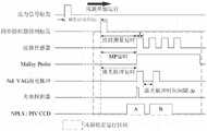
图2是本发明优选实施例的超声速流场气动光学效应风洞综合测试平台的的时序控制示意图。FIG. 2 is a schematic diagram of timing control of a wind tunnel comprehensive test platform for supersonic flow field aero-optical effects according to a preferred embodiment of the present invention.
图3是本发明优选实施例中利用光电探测器确定的NPLS/PIV测试的记录数据时刻。FIG. 3 is the recorded data moment of the NPLS/PIV test determined by the photodetector in the preferred embodiment of the present invention.
图4是本发明优选实施例的第一隔腔安装在实验段的上侧板上的结构示意图。FIG. 4 is a schematic structural diagram of the first compartment installed on the upper side plate of the experimental section according to the preferred embodiment of the present invention.
图5是本发明优选实施例的第一隔腔的光学隔腔和光学玻璃的安装结构示意图。5 is a schematic diagram of the installation structure of the optical compartment and the optical glass of the first compartment according to the preferred embodiment of the present invention.
图6是本发明优选实施例的第一隔腔的光学隔腔和光学玻璃的爆炸结构示意图。6 is a schematic diagram of an explosion structure of the optical compartment and the optical glass of the first compartment of the preferred embodiment of the present invention.
图7是本发明优选实施例的带后台阶的实验板的结构示意图。7 is a schematic structural diagram of an experimental board with a rear step according to a preferred embodiment of the present invention.
图8是本发明优选实施例的超声速气膜形成喷管的结构示意图。8 is a schematic structural diagram of a supersonic gas film forming nozzle according to a preferred embodiment of the present invention.
附图标记说明Description of reference numerals
1、第一隔腔;2、第二隔腔;3、激光光源;4、激光器;5、半透半反镜;6、波前探测装置;7、第一位置探测器;8、光阑;9、空间滤波器;10、第二位置探测器;11、实验模型;12、立刀;13、光学隔腔;14、光学玻璃;141、第一密封圈;142、第二密封圈;131、第三密封圈;132、第四密封圈;111、带后台阶的实验板;112、超声速气膜形成喷管;113、超声速气膜供气管路;1121、密封条;1111、前板体;1112、后板体;1113、凹槽;1114、进气孔;100、气体供给转接接头。1. First compartment; 2. Second compartment; 3. Laser light source; 4. Laser; 5. Semi-transparent mirror; 6. Wavefront detection device; 7. First position detector; 8. Aperture ; 9, spatial filter; 10, second position detector; 11, experimental model; 12, vertical knife; 13, optical compartment; 14, optical glass; 141, first sealing ring; 142, second sealing ring; 131, the third sealing ring; 132, the fourth sealing ring; 111, the experimental board with the rear step; 112, the supersonic air film forming nozzle; 113, the supersonic air film air supply pipeline; 1121, the sealing strip; 1111, the front plate body; 1112, rear plate body; 1113, groove; 1114, air inlet; 100, gas supply adapter.
具体实施方式Detailed ways
以下结合附图对本发明的实施例进行详细说明,但是本发明可以由下述所限定和覆盖的多种不同方式实施。The embodiments of the present invention will be described in detail below with reference to the accompanying drawings, but the present invention can be implemented in many different ways as defined and covered below.
如图1至图6所示,本发明的优选实施例提供一种超声速流场气动光学效应风洞综合测试平台,用于设置在风洞的实验段进行气动光学效应测试,其包括第一隔腔1、第二隔腔2、激光光源3、激光器4、半透半反镜5、波前探测装置6、第一位置探测器7、光阑8和CCD相机(图未示),所述第一隔腔1密封安装在风洞设备实验段的上侧板上,所述第二隔腔2密封安装在风洞设备实验段的下侧板上,且所述第一隔腔1和第二隔腔2相对设置,第一隔腔1和第二隔腔2之间的流场即为测试区域。所述激光光源3位于所述第二隔腔2的外侧,用于发出连续激光,所述光阑8设置在所述第二隔腔2内并位于连续激光的传输路径上,用于调节光学孔径的大小。所述半透半反镜5位于所述第一隔腔1的外侧,用于将穿过第二隔腔2和第一隔腔1后的连续激光分为两条传输光路,所述第一位置探测器7和波前探测装置6分别位于两条光路上,所述第一位置探测器7用于获取MP测试所需的信息,所述波前探测装置6用于获取波前测试所需的信息。所述激光器4位于所述第一隔腔1的外侧,用于发出激光脉冲,CCD相机位于所述第二隔腔2的外侧,用于拍摄超声速气流中示踪粒子的粒子图像并获取NPLS(Nano-tracer-based Planar Laser Scattering,平面激光散射)测试和PIV测试所需的信息。As shown in FIGS. 1 to 6 , a preferred embodiment of the present invention provides a wind tunnel comprehensive test platform for supersonic flow field aero-optical effects, which is used for testing aero-optical effects in the experimental section of the wind tunnel, which includes a
其中,所述激光光源3为连续激光光源,连续激光在依次穿过第二隔腔2、测试区域流场、第一隔腔1后被半透半反镜5分成两条传输光路,波前探测装置6设置在其中一条光路上,用于采集波前测试所需的畸变波前信息,以便于进行波前测试,第一位置探测器7设置在另一条光路上,用于采集光学孔径内流场导致的光线偏移信息,以便于进行MP测试,利用半透半反镜5可以获取相同区域内不同类型的气动光学效应信息,有利于提高气动光学效应测试的准确性和可靠性。所述激光器4为双腔Nd:YAG激光器,其可以发出激光脉冲,激光脉冲在依次穿过第一隔腔1、测试区域流场、第二隔腔2后被CCD相机所捕捉,而风洞的超声速气流内部署有微量的纳米示踪粒子,CCD相机可以拍摄纳米示踪粒子的粒子图像,从而获得NPLS测试所需的平面激光散射信息和PIV测试所需的粒子图像速度场信息,以便于进行NPLS测试和PIV测试。其中,平面激光散射信息和粒子图像速度场信息为流场参数信息,畸变波前信息和光线偏移信息则为气动光学效应参数信息。The
另外,考虑到气动光学效应测试受到光路积分效应影响,本发明设计特定的结构来消除风洞壁面边界层对于测试结果的影响,以保证测试结果的准确性,具体通过在测试区域上方设置密封安装的第一隔腔1,可以消除风洞上壁面湍流边界层的影响,通过在测试区域下方设置密封安装的第二隔腔2,可以消除风洞下壁面湍流边界层的影响,从而保证风洞上下壁面湍流边界层不会对光线传输产生干扰,大大提升了气动光学效应测试的准确性。In addition, considering that the aero-optical effect test is affected by the optical path integral effect, the present invention designs a specific structure to eliminate the influence of the boundary layer of the wind tunnel wall on the test results, so as to ensure the accuracy of the test results. Specifically, a sealed installation is provided above the test area. The
可以理解,本实施例的超声速流场气动光学效应风洞综合测试平台,在同一风洞运行车次下可以同时进行波前测试、MP测试、NPLS测试和PIV测试,单次测量获取的信息量大,有效节约了风洞运行车次,降低了实验成本,并且可以同步获取流场参数信息和气动光学效应相关参数,有助于分析气动光学效应内在的流动机理。并且,利用半透半反镜5可以获取相同区域内不同类型的气动光学效应信息,有利于提高气动光学效应测试的准确性和可靠性。另外,还通过在测试区域上方设置密封安装的第一隔腔1,可以消除风洞上壁面湍流边界层的影响,通过在测试区域下方设置密封安装的第二隔腔2,可以消除风洞下壁面湍流边界层的影响,从而保证风洞上下壁面湍流边界层不会对光线传输产生干扰,大大提升了气动光学效应测试的准确性。It can be understood that the wind tunnel comprehensive test platform for supersonic flow field aero-optical effect in this embodiment can perform wavefront test, MP test, NPLS test and PIV test at the same time under the same wind tunnel operation, and the amount of information obtained by a single measurement is large. , which effectively saves the number of trips in the wind tunnel and reduces the experimental cost, and can simultaneously obtain the flow field parameter information and the related parameters of the aero-optical effect, which is helpful to analyze the inherent flow mechanism of the aero-optical effect. In addition, different types of aero-optical effect information in the same area can be obtained by using the
可以理解,所述超声速流场气动光学效应风洞综合测试平台还包括多通道高精度同步控制器(图未示),所述多通道高精度同步控制器分别与CCD相机、波前探测装置6、第一位置探测器7和风洞的压力传感器连接。如图2所示,在进行测试时,所述多通道高精度同步控制器利用风洞的压力传感器检测到风洞开始运行时的压力跃升信号作为同步控制触发信号,并延长预设时间后控制CCD相机、波前探测装置6、第一位置探测器7进行同步采集。其中,进行数据采集时,风洞处于稳定运行阶段。另外,如图3所示,还可以利用光电探测器记录双腔Nd:YAG激光器的出光时刻,即定位NPLS/PIV技术测试数据时刻。It can be understood that the supersonic flow field aero-optical effect wind tunnel comprehensive test platform also includes a multi-channel high-precision synchronization controller (not shown in the figure), and the multi-channel high-precision synchronization controller is respectively connected with the CCD camera and the wavefront detection device 6 . , The
其中,所述激光器4发出的激光脉冲波长为532nm,所述激光光源3发出的连续激光波长为632.8nm,为了避免波前测试和MP测试采用的连续激光对NPLS/PIV测试造成干扰,所述CCD相机的镜头前方安装有包含632.8nm波段的陷波滤光片,从而可以消除连续激光对NPLS测试和PIV测试的干扰,保证了NPLS/PIV测试的准确性。Wherein, the laser pulse wavelength emitted by the laser 4 is 532 nm, and the continuous laser wavelength emitted by the
可选地,所述激光光源3和光阑8之间还设置有用于缩束和滤波的空间滤波器9,一方面便于根据实验要求改变光束的大小,另一方面可以滤除激光中的高频成本,保证光斑质量。另外,所述光阑8为一个可以连续调节的圆形光阑,其可以调节波前测试的光学孔径,测试光学孔径可以在0.1mm~20mm范围内变化。Optionally, a
可选地,所述超声速流场气动光学效应风洞综合测试平台还包括用于记录环境及测试系统噪声的第二位置探测器10,为后期对第一位置探测器7的记录数据进行数据噪声滤除提供依据。当对第一位置探测器7采集的数据进行处理时,需要以第二位置探测器10采集的数据作为数据噪声,对第一位置探测器7采集的数据进行数据噪声去除,消除环境及测试系统噪声对于MP测试的干扰,从而保证MP测试的准确性。Optionally, the supersonic flow field aero-optical effect wind tunnel comprehensive test platform also includes a
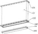
可以理解,所述第一隔腔1和第二隔腔2的结构相同,两者结构呈镜像,故在此以第一隔腔1的结构来做示例性说明,第二隔腔2的结构在此不再赘述。如图4至图8所示,所述第一隔腔1包括实验模型11、立刀12、光学隔腔13和光学玻璃14,所述光学隔腔13为两端敞口的腔体结构,所述光学隔腔13的顶部密封安装在风洞实验段的上侧板上,所述立刀12安装在所述风洞实验段的上侧板上并位于所述光学隔腔13的前方,所述实验模型11密封安装在所述立刀12和光学隔腔13的底部,所述实验模型11上开设有玻璃安装孔,所述光学玻璃14密封安装在所述玻璃安装孔内,激光穿过光学玻璃14进入测试区域流场。其中,所述立刀12和光学隔腔13可以是一体式结构,也可以是分体式结构,本发明优选采用分体式结构,比于整体加工而言可以显著降低加工成本。可以理解,所述第一隔腔1通过设置密封的光学隔腔13来传输激光,激光的传输不会受到风洞上壁面湍流边界层的影响,保证了气动光学效应测试的准确性。It can be understood that the structures of the
另外,所述立刀12的前缘需要削尖,并使前缘夹角尽可能的小,以减小其在风洞的超声速气流流场中产生斜基波的强度,避免实验模型11的下部流动压力过高造成直连式风洞溢流堵塞,作为优选的,所述立刀12的前缘夹角为15°~30°,一方面便于进行立刀12的设计加工,另一方面也有效减小了斜基波的强度。In addition, the leading edge of the
可以理解,所述光学玻璃14带有台阶,所述实验模型11上的玻璃安装孔为台阶孔,所述光学玻璃14的台阶面与所述玻璃安装孔的台阶面之间设置有第一密封圈141,所述光学玻璃14的顶面与所述光学隔腔13的底面之间设置有第二密封圈142。通过第一密封圈141来保证光学玻璃14与实验模型11之间的密封需求,通过第二密封圈142可以使得光学玻璃14与光学隔腔13压紧,保证了两者之间的密封性。It can be understood that the
另外,所述光学隔腔13的顶面与风洞实验段的上侧板之间设置有第三密封圈131,所述光学隔腔13的底面与所述实验模型11之间设置有第四密封圈132。通过第三密封圈131实现光学隔腔13与风洞实验段的上侧板之间的密封,通过第四密封圈132实现光学隔腔13与实验模型11之间的密封,保证光学隔腔13的内部不会与流场连通。In addition, a
可以理解,气动光学效应测试主要研究的是风洞内超声速气流经过实验模型11后产生的流场结构对于光线传输的影响,其中,实验模型11的结构设计不同,对于光线传输的影响也不同。其中,所述实验模型11可以选择层流平板、超声速气膜实验板或者其它结构的实验板。在本发明中,以第一隔腔1的实验模型11为层流平板,第二隔腔2的实验模型11为超声速气膜实验板来做示例性说明。当然,在本发明的其它实施例中,两个隔腔的实验模型11也可以均采用层流平板,此时主要研究平板边界层对于光线传输的影响,或者,第一隔腔1采用超声速气膜实验板,第二隔腔2采用层流平板。另外,本发明也对超声速气膜实验板的结构进行了创新性设计,具体地,所述超声速气膜实验板包括带后台阶的实验板111、超声速气膜形成喷管112和超声速气膜供气管路113,所述带后台阶的实验板111密封安装在所述光学隔腔13和立刀12的顶部,所述带后台阶的实验板111在对应光学隔腔13顶部敞口的位置处开设了带台阶的玻璃安装孔,所述光学玻璃14即安装在该玻璃安装孔内。所述超声速气膜形成喷管112可拆卸地密封安装在所述带后台阶的实验板111上,所述超声速气膜供气管路113安装在所述带后台阶的实验板111上,所述超声速气膜供气管路113分别与外部气源、所述超声速气膜形成喷管112连通,用于为超声速气膜形成喷管112提供冷却气体,其中,外部气源可以选择与风洞共用一个气源。在进行气动光学效应测试时,所述超声速气膜形成喷管112可以在测试区域形成超声速冷却气膜流场,当激光穿过超声速冷却气膜流场时会受到流场影响而发生偏移,然后通过相关传感器采集信息同步进行波前测试、MP测试、NPLS测试和PIV测试。具体地,所述超声速气膜形成喷管112在周向上开设有多个安装螺孔,所述超声速气膜形成喷管112与所述带后台阶的实验板111通过螺钉连接,装拆十分方便。所述超声速气膜形成喷管112的喷管型面通常采用B样条曲线喷管设计方法进行设计,可以根据不同的马赫数设计不同的喷管型面,当需要适用于不同的马赫数时,只需要单独更换超声速气膜形成喷管112即可,而无需更换整个实验模型11。另外,所述超声速气膜形成喷管112的底面上沿周向布设有密封条1121,从而对超声速气膜形成喷管112进行有效密封,仅允许超声速冷却气膜从出口处喷出,同时也保证了喷管型面的安装精度。It can be understood that the aero-optical effect test mainly studies the influence of the flow field structure generated by the supersonic airflow in the wind tunnel after passing through the
可选地,所述带后台阶的实验板111包括一体式结构的前板体1111和后板体1112,所述前板体1111和后板体1112之间设计有台阶过渡,所述玻璃安装孔即开设在所述后板体1112上,所述超声速气膜形成喷管112安装在所述前板体1111上,所述前板体1111在所述超声速气膜形成喷管112的安装位置处设置有凹槽1113,用于形成大容积扁平喷管驻室,大容积扁平喷管驻室的结构设计可以满足上台阶部分区域的内部冷却需求,从而保证形成的超声速冷却气膜流场分布更加均匀。所述凹槽1113内设置有进气孔1114,所述进气孔1114与所述超声速气膜供气管路113密封连接,冷却气体经超声速气膜供气管路113、进气孔1114进入到凹槽1113内,然后通过超声速气膜形成喷管112喷出形成超声速冷却气膜。Optionally, the
可选地,风洞实验段的上侧板和/或下侧板上还设置有气体供给转接接头100,所述气体供给转接接头100分别与所述超声速气膜供气管路113、气源连接。由于整个测试平台放置在风洞设备的实验段内,为了便于供气管路的布置,在风洞实验段的上侧板和/或下侧板上设置气体供给转接接头100来实现气源与超声速气膜供气管路113之间的连通。Optionally, the upper side plate and/or the lower side plate of the wind tunnel experimental section is also provided with a
另外,所述风洞实验段的上侧板和/或下侧板上还设置有穿线板,用于供传感器线路穿过,一方面满足了多样化的测试需求,另一方面也保证了密封性。In addition, the upper side plate and/or the lower side plate of the wind tunnel experimental section is also provided with a threading plate for the sensor circuit to pass through. sex.
以上所述仅为本发明的优选实施例而已,并不用于限制本发明,对于本领域的技术人员来说,本发明可以有各种更改和变化。凡在本发明的精神和原则之内,所作的任何修改、等同替换、改进等,均应包含在本发明的保护范围之内。The above descriptions are only preferred embodiments of the present invention, and are not intended to limit the present invention. For those skilled in the art, the present invention may have various modifications and changes. Any modification, equivalent replacement, improvement, etc. made within the spirit and principle of the present invention shall be included within the protection scope of the present invention.
Claims (10)
Priority Applications (1)
| Application Number | Priority Date | Filing Date | Title |
|---|---|---|---|
| CN202210291259.0ACN114754967B (en) | 2022-03-23 | 2022-03-23 | Supersonic flow field aerodynamic optical effect wind tunnel comprehensive test platform |
Applications Claiming Priority (1)
| Application Number | Priority Date | Filing Date | Title |
|---|---|---|---|
| CN202210291259.0ACN114754967B (en) | 2022-03-23 | 2022-03-23 | Supersonic flow field aerodynamic optical effect wind tunnel comprehensive test platform |
Publications (2)
| Publication Number | Publication Date |
|---|---|
| CN114754967Atrue CN114754967A (en) | 2022-07-15 |
| CN114754967B CN114754967B (en) | 2024-07-19 |
Family
ID=82327568
Family Applications (1)
| Application Number | Title | Priority Date | Filing Date |
|---|---|---|---|
| CN202210291259.0AActiveCN114754967B (en) | 2022-03-23 | 2022-03-23 | Supersonic flow field aerodynamic optical effect wind tunnel comprehensive test platform |
Country Status (1)
| Country | Link |
|---|---|
| CN (1) | CN114754967B (en) |
Cited By (3)
| Publication number | Priority date | Publication date | Assignee | Title |
|---|---|---|---|---|
| CN115585838A (en)* | 2022-09-26 | 2023-01-10 | 中国科学院工程热物理研究所 | Gas film flow field measuring device and using method thereof |
| CN116067611A (en)* | 2023-02-17 | 2023-05-05 | 中国工程物理研究院应用电子学研究所 | Method and device for testing aerodynamic flow field |
| CN117969012A (en)* | 2024-03-28 | 2024-05-03 | 中国空气动力研究与发展中心高速空气动力研究所 | Multi-period phase shifting synchronous measurement method for flow display of wind tunnel dynamic test |
Citations (5)
| Publication number | Priority date | Publication date | Assignee | Title |
|---|---|---|---|---|
| EP0538126A1 (en)* | 1991-10-18 | 1993-04-21 | Office National D'etudes Et De Recherches Aerospatiales | Method and device for analysing the wavefront of light |
| JP2008051757A (en)* | 2006-08-28 | 2008-03-06 | Tokyo Electric Power Co Inc:The | Laser light sheet forming device |
| CN102853918A (en)* | 2012-08-24 | 2013-01-02 | 中国人民解放军国防科学技术大学 | Pneumatic optical wavefront ultra-high frequency measurement system and method |
| CN108663190A (en)* | 2018-03-26 | 2018-10-16 | 中国人民解放军国防科技大学 | Transient wavefront test platform and system based on hypersonic pulse wind tunnel |
| CN112113738A (en)* | 2020-09-04 | 2020-12-22 | 中国空气动力研究与发展中心高速空气动力研究所 | Loop shearing interference system for measuring density field of boundary layer of wind tunnel flow field |
- 2022
- 2022-03-23CNCN202210291259.0Apatent/CN114754967B/enactiveActive
Patent Citations (5)
| Publication number | Priority date | Publication date | Assignee | Title |
|---|---|---|---|---|
| EP0538126A1 (en)* | 1991-10-18 | 1993-04-21 | Office National D'etudes Et De Recherches Aerospatiales | Method and device for analysing the wavefront of light |
| JP2008051757A (en)* | 2006-08-28 | 2008-03-06 | Tokyo Electric Power Co Inc:The | Laser light sheet forming device |
| CN102853918A (en)* | 2012-08-24 | 2013-01-02 | 中国人民解放军国防科学技术大学 | Pneumatic optical wavefront ultra-high frequency measurement system and method |
| CN108663190A (en)* | 2018-03-26 | 2018-10-16 | 中国人民解放军国防科技大学 | Transient wavefront test platform and system based on hypersonic pulse wind tunnel |
| CN112113738A (en)* | 2020-09-04 | 2020-12-22 | 中国空气动力研究与发展中心高速空气动力研究所 | Loop shearing interference system for measuring density field of boundary layer of wind tunnel flow field |
Non-Patent Citations (3)
| Title |
|---|
| 刘洪;陈方;励孝杰;郑忠华;肖保国;: "高速复杂流动PIV技术研究实践与挑战", 实验流体力学, no. 01, 15 February 2016 (2016-02-15)* |
| 吴玉迟;张保汉;谷渝秋;杨朝文;葛芳芳;王磊;王红斌;刘红杰;陈家斌;何颖玲;郑志坚;: "激光干涉技术在超声速气体喷嘴特性研究中的应用", 应用光学, no. 05, 15 September 2007 (2007-09-15)* |
| 易仕和;陈植;朱杨柱;何霖;武宇;: "(高)超声速流动试验技术及研究进展", 航空学报, no. 01, 25 January 2015 (2015-01-25)* |
Cited By (3)
| Publication number | Priority date | Publication date | Assignee | Title |
|---|---|---|---|---|
| CN115585838A (en)* | 2022-09-26 | 2023-01-10 | 中国科学院工程热物理研究所 | Gas film flow field measuring device and using method thereof |
| CN116067611A (en)* | 2023-02-17 | 2023-05-05 | 中国工程物理研究院应用电子学研究所 | Method and device for testing aerodynamic flow field |
| CN117969012A (en)* | 2024-03-28 | 2024-05-03 | 中国空气动力研究与发展中心高速空气动力研究所 | Multi-period phase shifting synchronous measurement method for flow display of wind tunnel dynamic test |
Also Published As
| Publication number | Publication date |
|---|---|
| CN114754967B (en) | 2024-07-19 |
Similar Documents
| Publication | Publication Date | Title |
|---|---|---|
| CN114754967A (en) | Wind tunnel comprehensive test platform for supersonic flow field aero-optic effect | |
| EP3382371B1 (en) | Aerosol real time monitor | |
| CN113324727B (en) | Schlieren image processing method for compressed corner supersonic flow field structure | |
| CN109297671B (en) | Particle image velocimetry test device for displaying flow of air flow field of airplane passenger cabin | |
| TWI824890B (en) | Diagnostic apparatuses and euv light source apparatuses | |
| KR102674160B1 (en) | Normal incidence in situ process monitor sensor | |
| CN114459727B (en) | Experimental system and method for SWTBLI unsteady characteristic research | |
| CN105043946B (en) | Angle of scattering self-calibration whole audience rainbow measuring method and device based on dual wavelength | |
| WO2017045605A1 (en) | Sensor for detecting particulate matter in air and method for manufacturing same | |
| US10588211B2 (en) | Radiation source having debris control | |
| CN108663190B (en) | Transient wavefront test platform and system based on hypersonic pulse wind tunnel | |
| JP2013079878A (en) | Method and apparatus for measuring fluid | |
| CN113899525B (en) | Compressible Reynolds stress measurement system based on combined schlieren technology | |
| CN103941038A (en) | Flow field flow velocity measuring device and method capable of eliminating vibration interference | |
| CN113551787A (en) | A simulation transposition for assessing the influence of the atmosphere on active remote sensing detection methods | |
| JP7485865B2 (en) | Analysis system and method for metal powder jets - Patents.com | |
| CN113093453A (en) | Multi-beam PIV lighting system | |
| CN114964718B (en) | Device for detecting jet cavitation and oscillation characteristics under confining pressure environment, and detecting method thereof | |
| ES2933279T3 (en) | Device and method for detecting the position of a laser beam | |
| RU2334206C1 (en) | Two-stage jet engine simulator | |
| CN117368197A (en) | Combustion gas flow field characteristic measurement method | |
| JP2008180630A (en) | Fluid measurement system, fluid measurement method, and computer program | |
| CN111811776A (en) | A method and system for measuring spray flow field | |
| Weisberger et al. | Self-aligned focusing schlieren at the 0.3-m Transonic Cryogenic Tunnel and the National Transonic Facility | |
| CN113063560A (en) | Measuring system and main system for flow field imaging |
Legal Events
| Date | Code | Title | Description |
|---|---|---|---|
| PB01 | Publication | ||
| PB01 | Publication | ||
| SE01 | Entry into force of request for substantive examination | ||
| SE01 | Entry into force of request for substantive examination | ||
| GR01 | Patent grant | ||
| GR01 | Patent grant |