CN114754885A - Three-dimensional thermopile and preparation method thereof - Google Patents
Three-dimensional thermopile and preparation method thereofDownload PDFInfo
- Publication number
- CN114754885A CN114754885ACN202210422757.4ACN202210422757ACN114754885ACN 114754885 ACN114754885 ACN 114754885ACN 202210422757 ACN202210422757 ACN 202210422757ACN 114754885 ACN114754885 ACN 114754885A
- Authority
- CN
- China
- Prior art keywords
- heat
- thermopile
- heat flow
- outer ring
- thermocouples
- Prior art date
- Legal status (The legal status is an assumption and is not a legal conclusion. Google has not performed a legal analysis and makes no representation as to the accuracy of the status listed.)
- Granted
Links
Images


Classifications
- G—PHYSICS
- G01—MEASURING; TESTING
- G01K—MEASURING TEMPERATURE; MEASURING QUANTITY OF HEAT; THERMALLY-SENSITIVE ELEMENTS NOT OTHERWISE PROVIDED FOR
- G01K7/00—Measuring temperature based on the use of electric or magnetic elements directly sensitive to heat ; Power supply therefor, e.g. using thermoelectric elements
- G01K7/02—Measuring temperature based on the use of electric or magnetic elements directly sensitive to heat ; Power supply therefor, e.g. using thermoelectric elements using thermoelectric elements, e.g. thermocouples
- G—PHYSICS
- G01—MEASURING; TESTING
- G01K—MEASURING TEMPERATURE; MEASURING QUANTITY OF HEAT; THERMALLY-SENSITIVE ELEMENTS NOT OTHERWISE PROVIDED FOR
- G01K17/00—Measuring quantity of heat
Landscapes
- Physics & Mathematics (AREA)
- General Physics & Mathematics (AREA)
- Chemical & Material Sciences (AREA)
- Engineering & Computer Science (AREA)
- Combustion & Propulsion (AREA)
- Investigating Or Analyzing Materials Using Thermal Means (AREA)
- Measuring Temperature Or Quantity Of Heat (AREA)
Abstract
Translated fromChinese
Description
Translated fromChinese技术领域technical field
本发明涉及热测量传感器技术领域。更具体地说,本发明涉及(但不限于)热分析仪器领域,尤其适用于差示量热法(DSC)或差示热分析仪器中的三维热电堆及其制备方法。The present invention relates to the technical field of thermal measurement sensors. More specifically, the present invention relates to (but is not limited to) the field of thermal analysis instruments, and is especially suitable for a three-dimensional thermopile in a differential calorimetry (DSC) or differential thermal analysis instrument and a preparation method thereof.
背景技术Background technique
差示热分析法同时向待测样品和参考材料供热以维持热平衡。当样品材料在物理和/或化学状态发生变化时,热量通过热量传感器与周围环境进行传导,并重新建立热平衡,热量传感器的电压对应传导的热流速率。热量传感器也称为热流传感器或导热式传感器。Differential thermal analysis simultaneously supplies heat to the test sample and reference material to maintain thermal equilibrium. When the physical and/or chemical state of the sample material changes, the heat is conducted with the surrounding environment through the heat sensor, and the heat balance is re-established, and the voltage of the heat sensor corresponds to the heat flow rate of conduction. Thermal sensors are also known as heat flow sensors or thermally conductive sensors.
热流传感器是利用不同金属或合金本身的热电效y应中的塞贝克效应(SeebeckEffect),它是指两种不同电导体或半导体首尾连接后,在首尾两端的温度差异产生了两端的电压差的热电现象。对于微弱的温度变化,单个热电偶结没有足够的检测灵敏度,需将多个热电偶结串联来实现放大温差信号,配合超低噪声信号放大器,可检测低至10nJ的微小热量变化。精密的微量热仪器往往具有数十至上千个热电偶结。The heat flow sensor uses the Seebeck effect in the thermoelectric effect of different metals or alloys, which means that after two different electrical conductors or semiconductors are connected end to end, the temperature difference between the ends of the two ends produces a voltage difference between the two ends. thermoelectric phenomenon. For weak temperature changes, a single thermocouple junction does not have sufficient detection sensitivity. Multiple thermocouple junctions need to be connected in series to amplify the temperature difference signal. With the ultra-low noise signal amplifier, it can detect small thermal changes as low as 10nJ. Precision microcalorimetry instruments often have tens to thousands of thermocouple junctions.
DSC(差示扫描量热仪)是目前广泛使用的量热仪器,用于测量物质热转变相关的温度和热量。工作温度范围通常从室温到300℃,有的甚至到1000℃以上,其热流测量传感器通常为二维平面结构。专利如CN200910126618.1和CN105209872A等均描述了一种平板形式的热分析传感器,数十对热电偶均布于陶瓷基板上,形成圆形分布。测量样品放置于小型坩埚内,坩埚底面与传感器接触来测量样品的热量。这种方式适用与小样品量和快速反应的场景。DSC (Differential Scanning Calorimeter) is a widely used calorimeter for measuring the temperature and heat associated with thermal transitions of substances. The operating temperature range is usually from room temperature to 300 °C, and some even to above 1000 °C, and the heat flow measurement sensor is usually a two-dimensional planar structure. Patents such as CN200910126618.1 and CN105209872A all describe a thermal analysis sensor in the form of a flat plate. Dozens of pairs of thermocouples are evenly distributed on the ceramic substrate to form a circular distribution. The measurement sample is placed in a small crucible, and the bottom surface of the crucible is in contact with the sensor to measure the heat of the sample. This method is suitable for scenarios with small sample size and rapid response.
专利CN01138265.1中提到了一种热量检测装置,其特征是在设有绝缘的大圆环和小圆环,大圆环和小圆环上各有相同数目的均匀分布的槽,热电偶被焊接成环状热电堆,构成一个热电堆单元。但其结构过于复杂,且过多的加工槽引起的尺寸误差可能导致热分布的不平衡。焊接后的热电偶节点存在与圆环接触面积的变化,也会影响传感器的传热均匀性。Patent CN01138265.1 mentions a heat detection device, which is characterized in that a large ring and a small ring are provided with insulation, the large ring and the small ring have the same number of evenly distributed grooves, and the thermocouple is Welded into a ring-shaped thermopile to form a thermopile unit. However, its structure is too complicated, and the dimensional error caused by too many machining grooves may lead to an unbalanced heat distribution. There is a change in the contact area between the welded thermocouple node and the ring, which will also affect the heat transfer uniformity of the sensor.
如果样品的热反应较缓慢,热量会分布于整个坩埚,约50%的热量通过没有接触传感器的坩埚表面以对流、辐射等方式向外散失,因此,对于缓慢反应,热焓测量准确率有限。另外,由于传感器是平面结构,其串联传感器数量也有限制,通常为20-50对,信号分辨率和仪器灵敏度有受此限制。If the thermal reaction of the sample is slow, the heat will be distributed throughout the crucible, and about 50% of the heat will be dissipated by convection, radiation, etc. through the crucible surface without contacting the sensor. Therefore, for slow reactions, the accuracy of enthalpy measurement is limited. In addition, due to the planar structure of the sensor, the number of serial sensors is also limited, usually 20-50 pairs, and the signal resolution and instrument sensitivity are limited by this.
再次,在涉及到催化、吸附、高压、真空等下条件反应时,需要2种甚至多种物质参与,或需要复杂的机构来实现混合、搅拌、水解等过程。由于现有DSC所使用的坩埚容积通常在100uL左右,受空间限制,这些反应也很难由DSC来实现。Thirdly, when it comes to catalysis, adsorption, high pressure, vacuum and other conditions, two or even multiple substances are required to participate, or a complex mechanism is required to realize processes such as mixing, stirring, and hydrolysis. Since the volume of the crucible used by the existing DSC is usually about 100uL, these reactions are also difficult to be realized by the DSC due to space constraints.
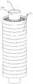
1948年,Calvet提出了传感器以3维方式包裹样品池,根据描述,实现的一种方式如图1,主视图为俯视图,B方向视图是单片的热电偶片,基材为石英或云母,在其表面分布约30对热电偶,每对热电偶两端以独立的金属薄片做为电偶丝的结合面,同时也作为其导热面。由16个热电偶片共同组成一个圆形热电堆。共480对热电偶。中心为容纳样品池的内通道管,热电堆外部紧贴具有圆孔的铝热沉。In 1948, Calvet proposed that the sensor wraps the sample cell in a 3-dimensional way. According to the description, one way to realize it is shown in Figure 1. The front view is a top view, and the B direction view is a single thermocouple sheet, and the substrate is quartz or mica. About 30 pairs of thermocouples are distributed on its surface, and the two ends of each pair of thermocouples use independent metal sheets as the joint surface of the galvanic wire and also as its heat conduction surface. A circular thermopile is composed of 16 thermocouple sheets. A total of 480 pairs of thermocouples. In the center is the inner channel tube that holds the sample cell, and the outside of the thermopile is close to an aluminum heat sink with a round hole.
当然地,现有技术为了得到较好的测量效果,对热流传感器的结构进行了改进,如申请号为202011232954.7的一种新型热电堆热流传感器,其通过两种不同材质的材料片的交叠放置,在两种不同材质的材料片之间通过热电偶实现电导通,由此形成热电堆形式以放大热电势差输出,达到增加热电堆热流传感器输出灵敏度系数的目的,但其应用场景是真实环境中的温度测量(如环境),其测量方式为平面式测量,其传感器与待测面直接接触,进而实现温度的测量,而对于实验室中应用研究来说,其测量环境不再局限于平面的测量,通常在具体的实验中,需要应用到的三维的精准测量效果,而当前的传感器并不能达到这一目的。Of course, in order to obtain a better measurement effect in the prior art, the structure of the heat flow sensor has been improved, such as a new type of thermopile heat flow sensor with application number 202011232954.7, which is placed by overlapping two material sheets of different materials. , Electric conduction is achieved through thermocouples between two material sheets of different materials, thereby forming a thermopile form to amplify the output of thermoelectric potential difference, and achieve the purpose of increasing the output sensitivity coefficient of the thermopile heat flow sensor, but its application scenario is in the real environment. The temperature measurement (such as the environment), the measurement method is plane measurement, the sensor is in direct contact with the surface to be measured, and then the temperature measurement is realized. For the application research in the laboratory, the measurement environment is no longer limited to the plane. Measurement, usually in specific experiments, needs to be applied to three-dimensional precise measurement effects, and current sensors cannot achieve this purpose.
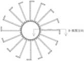
图8-9为现有技术中的一种三维形式的三维热流传感器的实现方式。容易看出,热电堆的接触面分别是外部匀热块的内环面和内部圆通道的外环面,并要求紧密配合。在温度升高的情况下,由于热电堆材料和外部铝热沉膨胀系数差别,接触面配合变差。如热电堆直径为38mm,外部热沉为铝,热膨胀系数为23.2e-6/K。热电偶材料为E型,镍络康铜15e-6/K。内通道为不锈钢管,外径17mm,当传感器温度从室温升高到300℃,根据圆形的热涨计算公式,配合面的间隙可由下面公式推导处:8-9 illustrate an implementation manner of a three-dimensional heat flow sensor in a three-dimensional form in the prior art. It is easy to see that the contact surfaces of the thermopile are the inner annular surface of the outer uniform heat block and the outer annular surface of the inner circular channel, respectively, and require a close fit. At elevated temperatures, the interface fit becomes poor due to differences in the coefficient of expansion of the thermopile material and the external aluminum heat sink. For example, the diameter of the thermopile is 38mm, the external heat sink is aluminum, and the thermal expansion coefficient is 23.2e-6/K. The thermocouple material is E type, nickel loconantan 15e-6/K. The inner channel is a stainless steel tube with an outer diameter of 17mm. When the temperature of the sensor rises from room temperature to 300°C, according to the circular thermal expansion calculation formula, the gap between the mating surfaces can be derived from the following formula:
Δd=d*ΔT(α1-a2);Δd=d*ΔT(α1-a2);
其中,d为热电堆半径;ΔT为温度升高值;α1为铝的热膨胀系数;α2为E型热电偶丝的热膨胀系数,不锈钢的热膨胀系数与E型热电偶丝的接近。Among them, d is the radius of the thermopile; ΔT is the temperature rise value; α1 is the thermal expansion coefficient of aluminum; α2 is the thermal expansion coefficient of the E-type thermocouple wire, and the thermal expansion coefficient of stainless steel is close to the E-type thermocouple wire.
从图中6可以发现,现有技术中的传感器,配合面间的间隙随温度升高而增加,例如,在300℃时,增加到40um,热电堆的导热能力下降,同时,增大了热电堆的响应时间,从热电堆的实际标定的量热系数随温度变化曲线也可以看出其明显变化。It can be found from Figure 6 that in the sensor in the prior art, the gap between the mating surfaces increases with the increase of temperature. For example, when the temperature increases to 40um at 300°C, the thermal conductivity of the thermopile decreases, and at the same time, the thermoelectricity increases. The response time of the stack can also be seen from the actual calibration curve of the thermopile's calorific coefficient versus temperature.
发明内容SUMMARY OF THE INVENTION
本发明的一个目的是解决至少上述问题和/或缺陷,并提供至少后面将说明的优点。SUMMARY OF THE INVENTION An object of the present invention is to address at least the above-mentioned problems and/or disadvantages and to provide at least the advantages that will be described hereinafter.
为了实现根据本发明的这些目的和其它优点,提供了一种三维热电堆,包括:To achieve these objects and other advantages in accordance with the present invention, a three-dimensional thermopile is provided, comprising:
多个呈堆叠状的环形热流传感器,中心处具有在空间上呈环状布局的传热通道;A plurality of stacked annular heat flow sensors, the center has a heat transfer channel in an annular layout in space;
穿设于各热流传感器中心的内筒;The inner cylinder passing through the center of each heat flow sensor;
其中,所述内筒被配置为与传热面紧密接触,且所述内筒被配置为具有超出顶层、底层热流传感器所在平面预定高度的热阻段;Wherein, the inner cylinder is configured to be in close contact with the heat transfer surface, and the inner cylinder is configured to have a thermal resistance section exceeding a predetermined height of the plane where the top and bottom heat flow sensors are located;
各热阻段通过相配合的垫高环、封口环进而封装,所述封口环上设置有与顶部或底部热流传感器引出头相配合的引出口。Each thermal resistance segment is encapsulated by a matching spacer ring and a sealing ring, and the sealing ring is provided with a lead-out port matched with the lead-out head of the top or bottom heat flow sensor.
优选的是,各环形热流传感器均被配置为包括:Preferably, each annular heat flow sensor is configured to include:
外环;outer ring;
设置于外环内部,以通过空间布局构成传热通道的多个导热机构;A plurality of heat conduction mechanisms arranged inside the outer ring to form heat transfer channels through spatial layout;
设置于外环与导热机构之间,以将各导热机构与外环连接构成一体的多组热电偶;It is arranged between the outer ring and the heat conduction mechanism to connect each heat conduction mechanism and the outer ring to form a plurality of sets of thermocouples;
其中,相邻热流传感器通过与各组热电偶呈连通状的至少两个引出头连接,实现多个热流传感器中热电偶的串联。Wherein, the adjacent heat flow sensors are connected through at least two lead-out heads that are in communication with each group of thermocouples, so as to realize the series connection of the thermocouples in the plurality of heat flow sensors.
优选的是,所述外环的内侧壁上设置有相配合的环形平台,以使外环的纵截面在空间上呈T形或L形结构,所述环形平台构成与各组热电偶相配合的导热面。Preferably, a matching annular platform is provided on the inner side wall of the outer ring, so that the longitudinal section of the outer ring has a T-shaped or L-shaped structure in space, and the annular platform is configured to cooperate with each group of thermocouples the heat transfer surface.
优选的是,所述外环、内筒的表面均设置有相配合的绝缘层;Preferably, the surfaces of the outer ring and the inner cylinder are provided with matching insulating layers;
其中,所述环形平台上卡设有多个U形或平板形结构的固定件,各组热电偶一端与对应的导热机构连接,另一端分别与相邻接的两个固定件连接,进而使得各组热电偶与固定件、导热机构在空间上呈串联状态。Wherein, the annular platform is clamped with a plurality of U-shaped or flat-shaped fixing parts, one end of each group of thermocouples is connected to the corresponding heat conduction mechanism, and the other end is connected to the two adjacent fixing parts respectively, so as to make Each group of thermocouples is spatially connected in series with the fixing member and the heat conduction mechanism.
优选的是,所述固定件的上表面、热电偶与固定件上表面的连接点上均设置有相配合的第一银浆层。Preferably, a matching first silver paste layer is provided on the upper surface of the fixing piece and the connection point between the thermocouple and the upper surface of the fixing piece.
优选的是,所述导热机构被配置为呈L形结构,以在空间上具有与热电偶相配合的安装面,以及与内筒相配合的传热面;Preferably, the heat conduction mechanism is configured in an L-shaped structure to spatially have a mounting surface matched with the thermocouple, and a heat transfer surface matched with the inner cylinder;
所述安装面的上表面、热电偶与安装面上表面的连接点上均设置有相配合的第二银浆层。A matching second silver paste layer is provided on the upper surface of the installation surface and the connection point between the thermocouple and the surface of the installation surface.
优选的是,各热阻段的长度被配置为25mm-35mm。Preferably, the length of each thermal resistance segment is configured to be 25mm-35mm.
一种制备三维热电堆的方法,包括:A method of preparing a three-dimensional thermopile, comprising:
步骤一,制备多个热流传感器;
步骤二,将上下相邻的热流传感器通过引出头进行连接,构成热电堆;
步骤三,将内筒穿设于热电堆中心,并使内筒两端向外延伸约30mm左右,构成热阻段;Step 3: Wear the inner cylinder in the center of the thermopile, and make the two ends of the inner cylinder extend outward by about 30mm to form a thermal resistance section;
步骤四,在各热阻段上分别设置相配合的垫高环、封口环,并使其中一侧的热流传感器的引出头穿出引出孔,得到三维热电堆。In
优选的是,在步骤一中,各热流传感器的制备方法被配置为包括:Preferably, in
S10,准备T形结构的外环,并对外环进行表面处理,以使其具有绝缘特性;S10, prepare the outer ring of the T-shaped structure, and perform surface treatment on the outer ring to make it have insulating properties;
S10,准备多个L结构的导热机构,每个导热机构的安装面上焊接两个热电偶,并使其在空间上呈V形布局;S10, prepare a plurality of L-structure heat-conducting mechanisms, and weld two thermocouples on the mounting surface of each heat-conducting mechanism, and make it a V-shaped layout in space;
S10,在外环上卡设多个固定件,将各导热机构上热电偶分别焊接在相邻固定件的上表面,以使各导热机构在空间上围绕外环构建呈环形布局的传热通道;S10, clamping a plurality of fixing pieces on the outer ring, and welding the thermocouples on each heat-conducting mechanism to the upper surface of the adjacent fixing pieces, so that each heat-conducting mechanism builds a heat transfer channel in a ring-shaped layout around the outer ring in space ;
S10,在外环的平台上设置一长、一短的两个引出头;S10, set up two leads, one long and one short, on the platform of the outer ring;
S10,分别在固定件、安装面的上表面,以及热电偶与固定件、安装面的连接点上涂覆银浆层。S10, respectively coating a silver paste layer on the upper surface of the fixing piece, the installation surface, and the connection point of the thermocouple, the fixing piece, and the installation surface.
优选的是,还包括:Preferably, it also includes:
步骤五,设置具有至少两个热电堆容纳腔的圆型热沉块,容纳腔被布置呈差分的方式,将其中一只作为参考,其它的作为测量,且各热电堆的封口环与容纳腔采用过盈配合或焊接的方式实现固定。Step 5: Set up a circular heat sink block with at least two thermopile accommodating cavities, the accommodating cavities are arranged in a differential manner, one of them is used as a reference, the other is used as a measurement, and the sealing ring of each thermopile is connected to the accommodating cavity. Fix by interference fit or welding.
本发明至少包括以下有益效果:本发明的热电堆,通过各部件的配合,在实验室中的热分析仪器进行配合时,可以实现对热的三维曲面热流测量,相对于现有的平面测量来说,其测量精度更高,能有效降低响应时间。The present invention includes at least the following beneficial effects: the thermopile of the present invention, through the cooperation of various components, can realize the three-dimensional curved surface heat flow measurement of heat when the thermal analysis instrument in the laboratory is matched, compared with the existing plane measurement. Said that its measurement accuracy is higher, which can effectively reduce the response time.
本发明的热流传感器(热电偶环)设置成环状结构,容易将多个热流传感器串联构成热电堆,在进行三维曲面热流测量时,热电堆与热沉导热的配合面,由现有的平面式热膨胀方向改为垂直式的热膨胀方向,极大的降低了传感器与匀热体配合面间隙,解决了配合间隙随温度升高而增大的问题,改善了传感器在高温下的量热系数,同时减小了传感器在全温度段的时间常数。The heat flow sensor (thermocouple ring) of the present invention is arranged in a ring structure, and it is easy to connect a plurality of heat flow sensors in series to form a thermopile. When the three-dimensional curved surface heat flow measurement is performed, the heat-conducting mating surface of the thermopile and the heat sink is formed by the existing plane. The thermal expansion direction of the type is changed to the vertical thermal expansion direction, which greatly reduces the gap between the sensor and the mating surface of the uniform heating body, solves the problem that the mating gap increases with the increase of temperature, and improves the calorific coefficient of the sensor at high temperature. At the same time, the time constant of the sensor in the full temperature range is reduced.
本发明的其它优点、目标和特征将部分通过下面的说明体现,部分还将通过对本发明的研究和实践而为本领域的技术人员所理解。Other advantages, objects, and features of the present invention will appear in part from the description that follows, and in part will be appreciated by those skilled in the art from the study and practice of the invention.
附图说明Description of drawings
图1为本发明的一个实施例中热电堆的外部结构示意图;1 is a schematic diagram of an external structure of a thermopile in an embodiment of the present invention;
图2为本发明的一个实施例中多个热流传感器与内筒配合的结构示意图;2 is a schematic structural diagram of a plurality of heat flow sensors mating with an inner cylinder in an embodiment of the present invention;
图3为本发明的一个实施例中热流传感器的侧视结构示意图;FIG. 3 is a schematic structural diagram of a side view of a heat flow sensor in an embodiment of the present invention;
图4为图3中K区的截面放大结构示意图;FIG. 4 is a schematic view of the enlarged cross-sectional structure of the K region in FIG. 3;
图5为本发明的另一个实施例中热流传感器的侧视结构示意图;FIG. 5 is a schematic structural diagram of a side view of a heat flow sensor in another embodiment of the present invention;
图6为本发明的一个实施例中热电堆与热沉块配合的结构示意图;FIG. 6 is a schematic structural diagram of the cooperation of a thermopile and a heat sink block in an embodiment of the present invention;
图7为本发明与现有技术的传感器中量热系数随温度变化曲线对比图;7 is a comparison diagram of the calorific coefficient variation curve with temperature in the sensor of the present invention and the prior art;
图8为现有技术中三维形式的三维热流传感器的其中一个视图;Figure 8 is one of the views of a three-dimensional heat flow sensor in a three-dimensional form in the prior art;
图9为图8的B向视图。FIG. 9 is a view taken along the line B of FIG. 8 .
具体实施方式Detailed ways
下面结合附图对本发明做进一步的详细说明,以令本领域技术人员参照说明书文字能够据以实施。The present invention will be further described in detail below with reference to the accompanying drawings, so that those skilled in the art can implement it with reference to the description.
应当理解,本文所使用的诸如“具有”、“包含”以及“包括”术语并不配出一个或多个其它元件或其组合的存在或添加。It should be understood that terms such as "having", "comprising" and "including" as used herein do not assign the presence or addition of one or more other elements or combinations thereof.
需要说明的是,在本发明的描述中,术语指示的方位或位置关系为基于附图所示的方位或位置关系,仅是为了便于描述本发明和简化描述,并不是指示或暗示所指的装置或元件必须具有特定的方位、以特定的方位构造和操作,因此不能理解为对本发明的限制。It should be noted that, in the description of the present invention, the azimuth or positional relationship indicated by the terms is based on the azimuth or positional relationship shown in the accompanying drawings, which is only for the convenience of describing the present invention and simplifying the description, and does not indicate or imply that A device or element must have a particular orientation, be constructed and operate in a particular orientation, and therefore should not be construed as limiting the invention.
在本发明的描述中,需要说明的是,除非另有明确的规定和限定,术语“安装”、“设置有”、“套设/接”、“连接”等,应做广义理解,例如“连接”,可以是固定连接,也可以是可拆卸连接,或一体地连接,可以是机械连接,也可以是电连接,可以是直接相连,也可以通过中间媒介间接相连,可以是两个元件内部的连通,对于本领域的普通技术人员而言,可以具体情况理解上述术语在本发明中的具体含义。In the description of the present invention, it should be noted that, unless otherwise expressly specified and limited, the terms "installation", "provided with", "sleeve/connection", "connection", etc., should be understood in a broad sense, such as " "connection", which can be a fixed connection, a detachable connection, or an integral connection, a mechanical connection, an electrical connection, a direct connection, or an indirect connection through an intermediate medium, or an internal connection between two components. For those of ordinary skill in the art, the specific meanings of the above terms in the present invention can be understood in specific situations.
图1-2示出了根据本发明的一种三维热电堆的实现形式,其中包括:Figures 1-2 show an implementation form of a three-dimensional thermopile according to the present invention, which includes:
多个呈堆叠状的环形热流传感器1,中心处具有在空间上呈环状布局的传热通道;a plurality of stacked annular
穿设于各热流传感器中心的内筒(内通道)2,内通道构成了热电堆的内传热部分,可选用的材料如铝、不锈钢、导热陶瓷等,其特征在于与所有导热机构的内传热面紧密相贴;The inner cylinder (inner channel) 2 which is inserted in the center of each heat flow sensor, the inner channel constitutes the inner heat transfer part of the thermopile, and the optional materials are aluminum, stainless steel, thermally conductive ceramics, etc. The heat transfer surfaces are closely attached;
其中,所述内筒被配置为与传热面紧密接触,且所述内筒被配置为具有超出顶层、底层热流传感器所在平面预定高度的热阻段210,各热阻段的长度被配置为25mm-35mm,做为优选的方案,各热阻段是内通道两端向外延伸约30mm以得到;Wherein, the inner cylinder is configured to be in close contact with the heat transfer surface, and the inner cylinder is configured to have
各热阻段通过相配合的垫高环3、封口环4进而封装,所述封口环上设置有与顶部或底部热流传感器引出头相配合的引出口(未示出),在实际应用时,选取高度合适的垫高环和封口环(垫高环与热电堆相配合,封口环与热电堆内通道相配合),填平内通道在首尾两端多出来的的高度,并在其中尾部的封口环留出热电偶的引出线开孔,在本方案中,通过将环形结构的热流传感器进行堆叠得到可以进行三维测量的热电堆,在实际应用时,待测的介质设置在多个热流传感器层叠后形成的传热通道中,改现有的平面测量方式为立体测量,在进行三维测量时,热电堆与热沉导热的配合面,由现有的平面式热膨胀方向改为垂直式的热膨胀方向,极大的降低了传感器与匀热体配合面间隙,解决了配合间隙随温度升高而增大的问题,改善了传感器在高温下的量热系数(如图7所示),同时减小了传感器在全温度段的时间常数。Each thermal resistance segment is encapsulated by the matching
如图3-5,在另一种实例中,各环形热流传感器均被配置为包括:As shown in Figure 3-5, in another example, each annular heat flow sensor is configured to include:
外环110,作为传感器的外圈导热环(或者称为外匀热环,作为一个等温体),采用导热率好的材料,如铝、高导热陶瓷进行制备;The
设置于外环内部,以通过空间布局构成传热通道的多个导热机构120,其是内圈传热用金属片,通过多个导热机构在空间上的布局,在中心处得到呈环状布局的传热通道,而热流传感器的堆叠,可以使传热通道根据需要进行延长,以适应具体的测量需要,而外环在空间上构成了外部的等温体,外部与导热机构之间通过热热电偶形成了传热通道,实现热能从外到内的传递;A plurality of
设置于外环与导热机构之间,以将各导热机构与外环连接构成一体的多组热电偶130;A plurality of sets of
其中,相邻热流传感器通过与各组热电偶呈连通状的引出头A 131,引出头B 132连接,在多个环状热流传感器中通过热电偶实现串联,实现多个热流传感器中热电偶的串联,在实际应用时,串联的热电偶具有一长一短的两个引出头,且较长的热电偶引出头长度应足够长,使其能与上面一层的热电偶环上的较短的引出头进行连接,通过多层环式热流传感器的叠加,可实现上百对的热电偶串联,而多层热流传感器的叠加能很容易构成了需要的热电堆,进一步地应用时,引出头可以设置在一边,使长的引出头穿过上一层的热流传感器与较短的引出头进行连接,也可以将两个引出头分别设置在上下两端,便于连接,而图3示出了容易在工程上进行制备的引出头引出方式,而传热机构在与引出头相配合的位置上设置单根热电偶或不设,其在空间上与固定件或其它部件进行连接,而固定件上设置相配合的延伸部,以对热电偶引出头进行固定,以及配合其它部件进行连接或位置固定,本方案的环式热流传感器,其在空间上呈环形结构布局,这使得通过多个热流传感器的堆叠后,在空间上可以具有与待测介质相配合的立体式传热通道,实现三维曲面热流测量,可广泛应用于实验室中需要进行热分析的场景中。Among them, the adjacent heat flow sensors are connected through the leading heads A 131 and
如图3、5,在另一种实例中,所述外环的内侧壁上设置有相配合的环形平台111,以使外环的纵截面在空间上呈T形或L形结构,所述环形平台构成与各组热电偶相配合的导热面,在这种结构中,外环向内伸出的部分构成了一个可以承载平台,作为与热电偶配合的导热面,在空间上其截面呈T型结构,在实际应用中,该平台为一个与外环在空间上呈垂直状态的环,结构完整,但在应用时,也可以根据需要进行开槽,但这种开槽会导致导热不均匀,故不做为优选的方案进行应用。3 and 5, in another example, a matching
如图3、5,在另一种实例中,所述外环、内筒的表面均设置有相配合的绝缘层(未示出),在实际应用时,通过对外环、内筒进行表面处理,使其表面具有膜性结构的绝缘层,具有表面绝缘的特性;As shown in Figures 3 and 5, in another example, the surfaces of the outer ring and the inner cylinder are provided with a matching insulating layer (not shown). In practical applications, the outer ring and the inner cylinder are surface treated , so that its surface has an insulating layer with a membranous structure, which has the characteristics of surface insulation;
其中,所述环形平台上卡设有多个U形或平板形结构的固定件140,各组热电偶一端与对应的导热机构连接,另一端分别与相邻接的两个固定件连接,进而使得各组热电偶与固定件、导热机构在空间上呈串联状态,在具体应用时,固定件为在平台上分布的约20个金属薄片,具体数量可由平台的周长等参数适当调整,金属薄片被设计为如图4的U型结构或如图5的平板形结构,而如果采用图4的U形结构,则根据应用需要,两条自由伸展的臂长可以相同或稍有差别;Wherein, the annular platform is clamped with a plurality of U-shaped or flat-plate-shaped fixing
在应用时,固定件的特点是两条在空间上呈U形布局的臂可以夹住平台,使得金属薄片制备的固定件不易发生位移,并且起到支撑电偶丝的作用,金属薄片与平台保证良好接触,在垂直方向形成稳定可靠的热传导路径。即便在高温下,因膨胀系数差别导致平台与金属片有相对水平位移情况下,由于导热方向为垂直方向,热流传导受到的影响可以忽略不计,且所有金属薄片与安装平台的接触面积相同,确保了经过电偶丝的热流能在所有方向上都可以均匀的流入或流出;In application, the feature of the fixture is that the two arms with a U-shaped layout in space can clamp the platform, so that the fixture made of metal sheet is not easy to be displaced, and plays the role of supporting the galvanic wire, the metal sheet and the platform Ensure good contact and form a stable and reliable heat conduction path in the vertical direction. Even at high temperature, when there is a relative horizontal displacement between the platform and the metal sheet due to the difference in the expansion coefficient, since the heat conduction direction is vertical, the influence of the heat flow conduction can be neglected, and the contact area between all the metal sheets and the mounting platform is the same to ensure that the So that the heat flow through the galvanic wire can flow in or out evenly in all directions;
所述固定件与导热面之间通过树脂层进而连接,其作用在于通过树脂层的粘接效果,实现固定件与导热面之间的固定式连接,保证各部件之间的稳定性。The fixing piece and the heat-conducting surface are further connected by the resin layer, and the function is to realize the fixed connection between the fixing piece and the heat-conducting surface through the bonding effect of the resin layer, so as to ensure the stability of each component.
如图3、5,在另一种实例中,所述固定件的上表面、热电偶与固定件上表面的连接点上均设置有相配合的第一银浆层(未示出),在实际应用时,金属薄片制备的固定件上部与热电偶130a,热电偶130b进行焊接,可选用的方式如激光焊接、点焊等,焊接后再以银浆涂覆焊接点和固定件的上表面,这样不仅减小热电偶130a,热电偶130b的接触电阻,同时也将热电偶的节点处的热量快速均匀的传导至固定件上,有利于减小传感器的热响应时间。As shown in Figures 3 and 5, in another example, a matching first silver paste layer (not shown) is provided on the upper surface of the fixing member and the connection point between the thermocouple and the upper surface of the fixing member. In practical application, the upper part of the fixing member made of metal sheet is welded with the
如图3、5,在另一种实例中,所述导热机构被配置为呈L形结构,以在空间上具有与热电偶相配合的安装面121,也是热电偶的焊接面,以及与内筒相配合的传热面122;As shown in Figures 3 and 5, in another example, the heat conduction mechanism is configured as an L-shaped structure to spatially have a mounting
所述安装面的上表面、热电偶与安装面上表面的连接点上均设置有相配合的第二银浆层(未示出),在本方案中,传感器的内部传热结构是L型的金属薄片,具有安装面和传热面,应用时安装面与热电偶130a、热电偶130b焊接在一起,同样通过银浆进行涂覆,用来减小接触电阻,同时将热电偶的节点处的热量快速均匀的传导至导热机构上,有利于减小传感器的热响应时间。A matching second silver paste layer (not shown) is arranged on the upper surface of the installation surface, the connection point between the thermocouple and the surface of the installation surface. In this solution, the internal heat transfer structure of the sensor is L-shaped. The metal sheet has a mounting surface and a heat transfer surface. During application, the mounting surface is welded with the
一种制备三维热电堆的方法,包括:A method of preparing a three-dimensional thermopile, comprising:
步骤一,制备多个热流传感器;
步骤二,将上下相邻的热流传感器通过引出头进行连接,构成热电堆;
步骤三,将内筒穿设于热电堆中心,并使内筒两端向外延伸约30mm左右,构成热阻段;Step 3: Wear the inner cylinder in the center of the thermopile, and make the two ends of the inner cylinder extend outward by about 30mm to form a thermal resistance section;
步骤四,在各热阻段上分别设置相配合的垫高环、封口环,并使其中一侧的热流传感器的引出头穿出引出孔,得到三维热电堆,采用这种方式得到的热电堆,其相对于现有技术而言,更有利于工程上的实现,且设备结构连接的可控性更好,可以根据需要进行组装,适应性更好。Step 4: Set up a matching spacer ring and a sealing ring on each thermal resistance section respectively, and make the lead-out of the heat flow sensor on one side pass through the lead-out hole to obtain a three-dimensional thermopile. The thermopile obtained in this way , compared with the prior art, it is more conducive to the realization of the project, and the controllability of the equipment structure connection is better, the assembly can be performed according to the needs, and the adaptability is better.
步骤五,如图6,设置具有至少两个热电堆容纳腔510的圆型热沉块5,容纳腔被布置呈差分的方式,将其中一只作为参考,其它的作为测量,且各热电堆的封口环与容纳腔采用过盈配合或焊接的方式实现固定,将热电堆放入外部圆型热沉块中,选取与传感器外环相同的材料,以消除热膨胀带来的问题。封口环与热沉采用过盈配合或焊接的方式,使两者相互固定。为提高抗干扰性能和扩展其应用,往往将完全相同的2支热电堆布置成差分的方式:一只作为参考,一只作为测量。Step 5, as shown in FIG. 6, set up a circular heat sink block 5 with at least two
在步骤一中,各热流传感器的制备方法被配置为包括:In
S10,准备T形结构的外环,并对外环进行表面处理,以使其具有绝缘特性;S10, prepare the outer ring of the T-shaped structure, and perform surface treatment on the outer ring to make it have insulating properties;
S10,准备多个L结构的导热机构,每个导热机构的安装面上焊接两个热电偶,并使其在空间上呈V形布局;S10, prepare a plurality of L-structure heat-conducting mechanisms, and weld two thermocouples on the mounting surface of each heat-conducting mechanism, and make it a V-shaped layout in space;
S10,在外环上卡设多个固定件,将各导热机构上热电偶分别焊接在相邻固定件的上表面,以使各导热机构在空间上围绕外环构建呈环形布局的传热通道;S10, clamping a plurality of fixing pieces on the outer ring, and welding the thermocouples on each heat-conducting mechanism to the upper surface of the adjacent fixing pieces, so that each heat-conducting mechanism builds a heat transfer channel in a ring-shaped layout around the outer ring in space ;
S10,在外环的平台上设置一长、一短的两个引出头;S10, set up two leads, one long and one short, on the platform of the outer ring;
S10,分别在固定件、安装面的上表面,以及热电偶与固定件、安装面的连接点上涂覆银浆层,通过这种方式获得对应的环式热流传感器,使得其在实际应用时,可以根据需要进行层叠,形成可以进行三维测量的热电堆,且工程实现上更为简单。S10, coat the silver paste layer on the fixing part, the upper surface of the installation surface, and the connection point of the thermocouple, the fixing part and the installation surface respectively, and obtain the corresponding ring heat flow sensor in this way, so that it can be used in practical applications. , which can be stacked as needed to form a thermopile capable of three-dimensional measurement, and the engineering implementation is simpler.
以上方案只是一种较佳实例的说明,但并不局限于此。在实施本发明时,可以根据使用者需求进行适当的替换和/或修改。The above solution is only an illustration of a preferred example, but not limited thereto. When implementing the present invention, appropriate substitutions and/or modifications may be made according to user needs.
这里说明的设备数量和处理规模是用来简化本发明的说明的。对本发明的应用、修改和变化对本领域的技术人员来说是显而易见的。The number of apparatuses and processing scales described here are intended to simplify the description of the present invention. Applications, modifications and variations to the present invention will be apparent to those skilled in the art.
尽管本发明的实施方案已公开如上,但其并不仅仅限于说明书和实施方式中所列运用。它完全可以被适用于各种适合本发明的领域。对于熟悉本领域的人员而言,可容易地实现另外的修改。因此在不背离权利要求及等同范围所限定的一般概念下,本发明并不限于特定的细节和这里示出与描述的图例。Although embodiments of the present invention have been disclosed above, they are not limited to the applications set forth in the specification and embodiments. It can be fully adapted to various fields suitable for the present invention. Additional modifications can readily be implemented by those skilled in the art. Therefore, the invention is not to be limited to the specific details and illustrations herein shown and described, without departing from the general concept defined by the appended claims and the scope of equivalents.
Claims (10)
Translated fromChinesePriority Applications (1)
| Application Number | Priority Date | Filing Date | Title |
|---|---|---|---|
| CN202210422757.4ACN114754885B (en) | 2022-04-21 | 2022-04-21 | Three-dimensional thermopile and preparation method thereof |
Applications Claiming Priority (1)
| Application Number | Priority Date | Filing Date | Title |
|---|---|---|---|
| CN202210422757.4ACN114754885B (en) | 2022-04-21 | 2022-04-21 | Three-dimensional thermopile and preparation method thereof |
Publications (2)
| Publication Number | Publication Date |
|---|---|
| CN114754885Atrue CN114754885A (en) | 2022-07-15 |
| CN114754885B CN114754885B (en) | 2025-03-14 |
Family
ID=82331428
Family Applications (1)
| Application Number | Title | Priority Date | Filing Date |
|---|---|---|---|
| CN202210422757.4AActiveCN114754885B (en) | 2022-04-21 | 2022-04-21 | Three-dimensional thermopile and preparation method thereof |
Country Status (1)
| Country | Link |
|---|---|
| CN (1) | CN114754885B (en) |
Cited By (1)
| Publication number | Priority date | Publication date | Assignee | Title |
|---|---|---|---|---|
| CN116631668A (en)* | 2023-04-10 | 2023-08-22 | 中国原子能科学研究院 | Power Generation Modules and Power Generation Devices |
Citations (7)
| Publication number | Priority date | Publication date | Assignee | Title |
|---|---|---|---|---|
| JP2004037097A (en)* | 2002-06-28 | 2004-02-05 | Eko Instruments Trading Co Ltd | Heat flow sensor and method of manufacture |
| JP2012255718A (en)* | 2011-06-09 | 2012-12-27 | Etou Denki Kk | Manufacturing method of heat flow sensor |
| CN110132451A (en)* | 2019-05-10 | 2019-08-16 | 中国电子科技集团公司第四十八研究所 | A kind of heat flow sensor and preparation method thereof |
| CN110836737A (en)* | 2019-12-11 | 2020-02-25 | 大连交通大学 | Film heat flowmeter based on high-temperature transient heat flow measurement and manufacturing method |
| CN111024269A (en)* | 2019-12-25 | 2020-04-17 | 中国计量大学 | Planar heat flow sensor for measuring heat flow along wall surface and calibration method thereof |
| CN112284572A (en)* | 2020-10-14 | 2021-01-29 | 杭州仰仪科技有限公司 | Thermopile type heat flow sensor for tower structure differential scanning calorimeter |
| CN113503981A (en)* | 2021-06-22 | 2021-10-15 | 中国科学院上海硅酸盐研究所 | Interlinked vertical sawtooth type thermopile heat flow sensor and manufacturing method thereof |
- 2022
- 2022-04-21CNCN202210422757.4Apatent/CN114754885B/enactiveActive
Patent Citations (7)
| Publication number | Priority date | Publication date | Assignee | Title |
|---|---|---|---|---|
| JP2004037097A (en)* | 2002-06-28 | 2004-02-05 | Eko Instruments Trading Co Ltd | Heat flow sensor and method of manufacture |
| JP2012255718A (en)* | 2011-06-09 | 2012-12-27 | Etou Denki Kk | Manufacturing method of heat flow sensor |
| CN110132451A (en)* | 2019-05-10 | 2019-08-16 | 中国电子科技集团公司第四十八研究所 | A kind of heat flow sensor and preparation method thereof |
| CN110836737A (en)* | 2019-12-11 | 2020-02-25 | 大连交通大学 | Film heat flowmeter based on high-temperature transient heat flow measurement and manufacturing method |
| CN111024269A (en)* | 2019-12-25 | 2020-04-17 | 中国计量大学 | Planar heat flow sensor for measuring heat flow along wall surface and calibration method thereof |
| CN112284572A (en)* | 2020-10-14 | 2021-01-29 | 杭州仰仪科技有限公司 | Thermopile type heat flow sensor for tower structure differential scanning calorimeter |
| CN113503981A (en)* | 2021-06-22 | 2021-10-15 | 中国科学院上海硅酸盐研究所 | Interlinked vertical sawtooth type thermopile heat flow sensor and manufacturing method thereof |
Cited By (1)
| Publication number | Priority date | Publication date | Assignee | Title |
|---|---|---|---|---|
| CN116631668A (en)* | 2023-04-10 | 2023-08-22 | 中国原子能科学研究院 | Power Generation Modules and Power Generation Devices |
Also Published As
| Publication number | Publication date |
|---|---|
| CN114754885B (en) | 2025-03-14 |
Similar Documents
| Publication | Publication Date | Title |
|---|---|---|
| CN102156148B (en) | Differential scanning calorimeter | |
| Martin | Apparatus for the high temperature measurement of the Seebeck coefficient in thermoelectric materials | |
| US8708556B2 (en) | Thermal analyzer | |
| CN105209872A (en) | Thermopile differential scanning calorimeter sensor | |
| CN108548608A (en) | A kind of 3D write-throughs aluminium oxide ceramics film heat flux sensor and preparation method thereof | |
| JP2008243990A (en) | Substrate heating device | |
| CN219015483U (en) | Temperature probe and insert for a temperature probe | |
| CN104122010B (en) | Radiation heat flow measuring device | |
| CN114754885A (en) | Three-dimensional thermopile and preparation method thereof | |
| CN114047223A (en) | Two sample coefficient of heat conductivity measuring device of steady state method | |
| CN108061738A (en) | The measuring device and method of a kind of sample thermal conductivity and thermoelectrical potential | |
| CN217032799U (en) | Ring type heat flow sensor | |
| CN110785641B (en) | Calorimeter with a heat measuring tube | |
| Ulanovskiy et al. | Tungsten–Rhenium Thermocouples Calibration in Ultra-High Temperature Range | |
| CN110530927A (en) | A kind of thermoelectric material Seebeck coefficient test device and method | |
| JP6059720B2 (en) | Differential calorimetric sensor and manufacturing method thereof | |
| US6422742B1 (en) | Differential scanning calorimeter | |
| CN114544038B (en) | A Gordon type heat flow meter and its self-correction method | |
| RU2839534C1 (en) | Method of thermophysical characteristics measuring and thermal sensor for implementation thereof | |
| CN107228718A (en) | A kind of thermoelectric pile detection means | |
| JP2007178218A (en) | Thermal resistance measuring device | |
| JPS62231148A (en) | Thermal analysis instrument | |
| US20230104380A1 (en) | Zone box for a differential scanning calorimeter | |
| CN118696218B (en) | Sensor for a system for measuring inertial heat flux | |
| EP1491881A1 (en) | Method and device for measuring thermophysical parameters of materials by pulse transient method |
Legal Events
| Date | Code | Title | Description |
|---|---|---|---|
| PB01 | Publication | ||
| PB01 | Publication | ||
| SE01 | Entry into force of request for substantive examination | ||
| SE01 | Entry into force of request for substantive examination | ||
| TA01 | Transfer of patent application right | ||
| TA01 | Transfer of patent application right | Effective date of registration:20230613 Address after:621000 Building 4, 389 Fujin Road, Fucheng District, Mianyang City, Sichuan Province Applicant after:Mianyang Weiyi Technology Co.,Ltd. Address before:621000 room 301-21, building 7, Keda Plaza, No. 8 Qingyang East Street, Qingyi Town, Fucheng District, Mianyang City, Sichuan Province Applicant before:Mianyang finali Technology Co.,Ltd. | |
| GR01 | Patent grant | ||
| GR01 | Patent grant |