CN114748241A - Intraocular forceps with membrane separation mechanism - Google Patents
Intraocular forceps with membrane separation mechanismDownload PDFInfo
- Publication number
- CN114748241A CN114748241ACN202110028298.7ACN202110028298ACN114748241ACN 114748241 ACN114748241 ACN 114748241ACN 202110028298 ACN202110028298 ACN 202110028298ACN 114748241 ACN114748241 ACN 114748241A
- Authority
- CN
- China
- Prior art keywords
- liquid
- membrane separation
- water
- separation mechanism
- working part
- Prior art date
- Legal status (The legal status is an assumption and is not a legal conclusion. Google has not performed a legal analysis and makes no representation as to the accuracy of the status listed.)
- Pending
Links
Images


Classifications
- A—HUMAN NECESSITIES
- A61—MEDICAL OR VETERINARY SCIENCE; HYGIENE
- A61F—FILTERS IMPLANTABLE INTO BLOOD VESSELS; PROSTHESES; DEVICES PROVIDING PATENCY TO, OR PREVENTING COLLAPSING OF, TUBULAR STRUCTURES OF THE BODY, e.g. STENTS; ORTHOPAEDIC, NURSING OR CONTRACEPTIVE DEVICES; FOMENTATION; TREATMENT OR PROTECTION OF EYES OR EARS; BANDAGES, DRESSINGS OR ABSORBENT PADS; FIRST-AID KITS
- A61F9/00—Methods or devices for treatment of the eyes; Devices for putting in contact-lenses; Devices to correct squinting; Apparatus to guide the blind; Protective devices for the eyes, carried on the body or in the hand
- A61F9/007—Methods or devices for eye surgery
- A61F9/00736—Instruments for removal of intra-ocular material or intra-ocular injection, e.g. cataract instruments
- A—HUMAN NECESSITIES
- A61—MEDICAL OR VETERINARY SCIENCE; HYGIENE
- A61F—FILTERS IMPLANTABLE INTO BLOOD VESSELS; PROSTHESES; DEVICES PROVIDING PATENCY TO, OR PREVENTING COLLAPSING OF, TUBULAR STRUCTURES OF THE BODY, e.g. STENTS; ORTHOPAEDIC, NURSING OR CONTRACEPTIVE DEVICES; FOMENTATION; TREATMENT OR PROTECTION OF EYES OR EARS; BANDAGES, DRESSINGS OR ABSORBENT PADS; FIRST-AID KITS
- A61F9/00—Methods or devices for treatment of the eyes; Devices for putting in contact-lenses; Devices to correct squinting; Apparatus to guide the blind; Protective devices for the eyes, carried on the body or in the hand
- A61F9/007—Methods or devices for eye surgery
Landscapes
- Health & Medical Sciences (AREA)
- Ophthalmology & Optometry (AREA)
- Heart & Thoracic Surgery (AREA)
- Surgery (AREA)
- Engineering & Computer Science (AREA)
- Biomedical Technology (AREA)
- Nuclear Medicine, Radiotherapy & Molecular Imaging (AREA)
- Vascular Medicine (AREA)
- Life Sciences & Earth Sciences (AREA)
- Animal Behavior & Ethology (AREA)
- General Health & Medical Sciences (AREA)
- Public Health (AREA)
- Veterinary Medicine (AREA)
- Prostheses (AREA)
Abstract
Description
Translated fromChinese技术领域technical field
本发明涉及一种用于眼内膜组织剥离用的眼内镊,特别是带膜分离机构的眼内镊。The invention relates to an intraocular forceps used for peeling endometrial tissue, in particular to an intraocular forceps with a membrane separation mechanism.
背景技术Background technique
视网膜前膜是一种常见眼底疾病,高发于黄斑部,其本质是由于视网膜细胞及其衍生物或代谢产物在视网膜前部形成的一层纤维膜,如覆盖住黄斑区,则称之为黄斑前膜。根据病因可分为特发性黄斑前膜和继发性黄斑前膜两大类型。Epiretinal membrane is a common fundus disease, which is most common in the macula. Its essence is a fibrous membrane formed by retinal cells and their derivatives or metabolites in the front of the retina. If it covers the macula, it is called the macula. anterior membrane. According to the etiology, it can be divided into two types: idiopathic epiretinal membrane and secondary epiretinal membrane.
特发性黄斑前膜的发生通常与玻璃体后脱离有关,而玻璃体后脱离时,对后极部产生牵引力,刺激细胞增生,内界膜的薄弱区受此牵引,容易产生破损。The occurrence of idiopathic epiretinal membrane is usually related to the posterior vitreous detachment, and when the posterior vitreous detachment occurs, it produces traction on the posterior pole, stimulates cell proliferation, and the weak area of the inner limiting membrane is easily damaged by this traction.
临床中,不论是对特发性黄斑前膜进行早期干预,还是对继发性黄斑前膜在原发眼部疾病治愈后的手术治疗,都需要进行前膜剥离,必要时还需要剥离病变的内界膜。In clinical practice, whether it is early intervention for idiopathic epiretinal membrane or surgical treatment of secondary epiretinal membrane after the primary ocular disease has been cured, it is necessary to perform epimembrane peeling, and when necessary, it is necessary to peel off the lesions. inner limiting membrane.
但黄斑前膜非常薄,而且通常与视网膜粘连紧密,尤其是内界膜更是紧密覆盖整个视网膜内表面的一层菲薄而透明的薄膜,且黄斑区感光细胞密集、血供丰富,利用眼内镊钳夹进行剥离时,容易发生出血、医源性撕裂孔,严重者甚至会产生视网膜脱离等严重并发症,对视力造成极大伤害,因此,需要对现有的眼内镊进行进一步改进。However, the epimacular membrane is very thin, and it is usually closely adhered to the retina. In particular, the inner limiting membrane is a thin and transparent film that closely covers the entire inner surface of the retina, and the macular area is dense with photoreceptor cells and rich in blood supply. When peeling with forceps, it is easy to cause bleeding, iatrogenic tear holes, and even severe complications such as retinal detachment, which cause great damage to vision. Therefore, it is necessary to further improve the existing intraocular forceps. .
发明内容SUMMARY OF THE INVENTION
本发明之带膜分离机构的眼内镊由于设计有膜分离机构,能实现眼内膜组织的分离,尤其是视网膜前膜和视网膜的分离,使得眼内镊的工作部能够非常方便地将分离后的眼内膜组织钳夹剥离后取出。The intraocular forceps with a membrane separation mechanism of the present invention is designed with a membrane separation mechanism, which can realize the separation of the endometrial tissue, especially the separation of the epiretinal membrane and the retina, so that the working part of the intraocular forceps can be easily separated. After the endometrial tissue was removed by clamp dissection.
本发明之带膜分离机构的眼内镊,其特征在于:所述带膜分离机构的眼内镊100含工作部1、连接机构2、膜分离机构3、控制机构4和手柄5;The intraocular forceps with membrane separation mechanism of the present invention is characterized in that: the intraocular forceps with
A、所述连接机构2的远端设有所述工作部1;所述连接机构2的近端设有所述手柄5;A. The distal end of the
B、所述控制机构4控制所述工作部1的张开或闭合;B. The
C、所述膜分离机构3能实现眼内膜组织的分离,所述工作部1将分离后的眼内膜组织进行钳夹剥离。C. The
临床手术时,先用所述膜分离机构3将眼内膜组织,尤其是视网膜前膜、或内界膜和视网膜分离,然后再用所述工作部1将分离后的眼内膜组织钳夹剥离。由于眼内膜组织已经和基底组织分离,因此,所述工作部1钳夹剥离时不容易损伤基底组织,不容易造成出血等情况,临床使用更加安全。During clinical operation, the
所述膜分离机构3是液体膜分离机构301。所述液体膜分离机构301以液体作为组织膜分离的动力源,利用液体的流动性和冲刷力,所述液体膜分离机构301能非常好地将需要剥离的膜组织和基底组织之间分离,即使是非常狭窄的位置,利用液体的流动性也能方便地到达。The
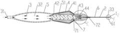
所述液体膜分离机构301含进水口31、水通道32及喷水口33,所述进水口31与液源200连通,在压力作用下,液体经所述进水口31进入所述水通道32后经所述喷水口33流出,所述喷水口33流出的液体冲刷眼内膜组织的结合部,分离眼内膜组织。所述液源200的液体可以被施压后从所述喷水口33喷出,在压力作用下,喷出的液体具有更好地冲击力,能够更好地对眼内膜组织进行分离。为保证液体能沿所述水通道32后仅能从所述喷水口33喷出,所述带膜分离机构的眼内镊100带有水密封机构7,所述水密封机构7可以是密封圈71,也可以是胶粘密封72,或者通过部件之间的注塑、焊接等方式实现液体流动过程的密封。The liquid membrane separation mechanism 301 includes a
所述喷水口31设置在所述工作部1的近端,当所述工作部1张开时,所述喷水口33流出的液体在所述工作部1呈水帘状;当所述工作部1闭合时,所述喷水口33流出的液体在所述工作部1呈水柱状。当液体呈水帘状时,可以大面积快速地对膜组织进行冲刷和分离,当液体呈水柱状时,可以对局部难分离位置进行精准定点冲击、分离。临床使用时,可以根据需要选用液体的冲刷状态。The
通过调节所述控制机构4可以控制所述工作部1的张开程度从而改变所述喷水口33流出的液体形成的水帘状水流的宽度。所述控制机构4可以控制所述工作部1的张开和闭合,临床使用中,根据需要分离的部位的形状选择水帘的宽度。By adjusting the
所述控制机构4是连杆式控制机构、或铰链式控制机构、或旋转式控制机构。申请人在此只列举了上述三种形式的控制机构,本领域的技术人员可以根据需要设计出不同作用形式的所述控制机构4,都并不脱离本申请的保护范围。The
所述控制机构4是连杆式控制机构4-1;所述连杆式控制机构4-1含控制开关41,按压所述控制开关41,所述连接机构2向后运动,所述工作部1闭合,松开所述控制开关41,所述连接机构2复位,所述工作部1张开。The
所述连杆式控制机构4-1含控制开关41、控制芯杆42、连接座43、复位弹簧44;所述控制芯杆42和所述连接座43连接,所述复位弹簧44设置在所述连接座43的外侧;所述控制芯杆42、连接座43和复位弹簧44设置在所述手柄5的壳体51内,所述控制开关41设置在所述壳体51的外侧,所述壳体51的远端设有鞘管6,所述连接机构2设置在鞘管6内,所述连接机构2的近端连接在所述连接座43上;按压所述控制开关41,所述控制芯杆42向后运动,带动所述连接座43向后运动,所述复位弹簧44压缩,从而使得所述连接机构2向后运动,连接在所述连接机构2远端的工作部1随之回退,进入所述鞘管6内,所述工作部闭合;松开所述控制开关41,在所述复位弹簧44的回复力作用下,所述连接座43向前运动,连接在所述连接座43上的所述连接机构2带动所述工作部1向前运动,所述工作部1从所述鞘管6远端伸出,所述工作部1张开。The link-type control mechanism 4-1 includes a
所述鞘管6的通孔61构成所述水通道32。The through
所述鞘管6一方面构成所述水通道32,液体经所述鞘管6排入眼内,另一方面所述鞘管6的端部61能控制所述工作部1的开口程度,随着所述控制芯杆42带动所述工作部1向所述鞘管6内回缩,所述工作部1逐渐闭合。On the one hand, the
所述液体膜分离机构301含液体开关34。所述液体开关34可以控制所述控制液体的流出和关闭。所述液体开关34可以是单独设置的开关机构,也可以和所述液源200集成在一起,如当所述液源200采用弹性储水球囊时,直接通过按压弹性储水球囊既可以实现所述液体开关34控制液体流出和关闭的功能。The liquid membrane separation mechanism 301 includes a
所述液体开关34设置在所述手柄5上或是脚踏开关。所述液体开关34可以设置在所述手柄5上,通过单手操作实现液体的流出和关闭,也可以设置成脚踏开关的形式,通过脚踏的形式来控制液体的流出和关闭。当然,本领域的技术人员还可以根据需要设计出其它不同的开关结构,申请人在此不一一举例说明,但都不脱离本申请的保护范围。The
所述液体膜分离机构301是手动液体膜分离机构3-1或电动液体膜分离机构3-2。The liquid membrane separation mechanism 301 is a manual liquid membrane separation mechanism 3-1 or an electric liquid membrane separation mechanism 3-2.
所述手动液体膜分离机构3-1可以直接控制液体的开启和关闭,使用过程方便,而且可以随时根据临床治疗过程进行及时控制。而所述电动液体膜分离机构3-2可以对液体的压力、流量和流速进行精确控制,并可以在控制界面上进行实时显示,临床应用过程可以实现膜分离过程中液体的定量控制。The manual liquid membrane separation mechanism 3-1 can directly control the opening and closing of the liquid, the use process is convenient, and it can be controlled in time according to the clinical treatment process at any time. The electric liquid membrane separation mechanism 3-2 can precisely control the pressure, flow and flow rate of the liquid, and can display it in real time on the control interface, and can realize the quantitative control of the liquid during the membrane separation process in the clinical application process.
所述液体膜分离机构301是所述手动液体膜分离机构3-1;所述手动液体膜分离机构3-1含进水口31、水通道32和喷水口33。The liquid film separation mechanism 301 is the manual liquid film separation mechanism 3-1; the manual liquid film separation mechanism 3-1 includes a
所述液源200是储水球囊201;所述进水口31设置在所述水通道32的近端,与所述储水球囊201连通,所述喷水口33设置在所述工作部1的近端,按压所述储水球囊201,所述储水球囊201里的液体被压迫后经所述进水口31进入所述水通道32,后经所述喷水口33排入眼内,对眼内膜组织进行冲刷分离。The
所述储水球囊201采用弹性材料制造,将所述储水球囊201设置成手握式,在临床应用中通过按压所述储水球囊201就可以将液体压出,不需要单独设置开关机构,结构简单,操作非常方便。The
也可以设置所述液体开关34,尤其是当所述储水球囊201采用非弹性材料制造时,可以通过控制所述液体开关34来实现所述储水球囊201中液体的排出。The
所述手动液体膜分离机构3-1还含液体开关34;所述液源200是放置在高处的储水容器202;所述进水口31设置在所述水通道32的近端,与所述储水容器202连通,所述喷水口33设置在所述工作部1的近端,所述液体开关34设置在所述手柄5上;放置在高处的所述储水容器202提供液体的流动动力,所述液体开关34可以控制液体的流出和关闭。通过调节所述储水容器202放置的高度,可以方便地调节液体的压力,临床使用非常方便。The manual liquid membrane separation mechanism 3-1 also includes a
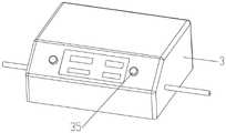
所述液体膜分离机构301是所述电动液体膜分离机构3-2;所述电动液体膜分离机构3-2含进水口31、水通道32、喷水口33、液体开关34、电路及控制系统35、蠕动泵36及水箱37;所述蠕动泵36一端与所述水箱37连接,另一端与液源200连接;在所述电路及控制系统35的作用下,所述蠕动泵36工作,所述液源200中的液体被吸入所述水箱37内,打开所述液体开关34,所述水箱内37中的液体经进水口31经所述水通道32后从所述喷水口33排入眼内,对眼内膜组织进行冲刷分离。所述电路及控制系统35可以控制所述蠕动泵36的工作,所述蠕动泵36可以更精确地控制液体的流量和速度。The liquid film separation mechanism 301 is the electric liquid film separation mechanism 3-2; the electric liquid film separation mechanism 3-2 includes a
所述液体膜分离机构301是所述电动液体膜分离机构3-2;所述电动液体膜分离机构3-2含进水口31、水通道32、液体开关34、电路及控制系统35、增压装置38及水箱37。The liquid film separation mechanism 301 is the electric liquid film separation mechanism 3-2; the electric liquid film separation mechanism 3-2 includes a
所述增压装置38是电动空气增压装置38-1或电动活塞增压装置38-2。The supercharging device 38 is an electric air supercharging device 38-1 or an electric piston supercharging device 38-2.
所述增压装置38是电动空气增压装置38-1;所述电动空气增压装置38-1含进风口38-11、充气管38-12和压缩机38-13,所述压缩机38-13工作时,空气经所述进风口38-11进入所述充气管38-12对所述水箱37内的液体进行增压,液体经增压后从所述进水口31进入所述水通道32,经所述喷水口33排入眼内,对眼内膜组织进行冲刷分离。The supercharging device 38 is an electric air supercharging device 38-1; the electric air supercharging device 38-1 includes an air inlet 38-11, a charging pipe 38-12 and a compressor 38-13, the compressor 38 -13 When working, the air enters the inflation pipe 38-12 through the air inlet 38-11 to pressurize the liquid in the
所述增压装置38是所述电动活塞增压装置38-2;所述电动活塞增压装置38-2含电机38-21、推杆38-22,所述水箱37含活动式底座37-1;在所述电路及控制系统35作用下,所述电机38-21工作,所述推杆38-22推动所述活动式底座37-1运动,所述水箱37里的液体在压力作用下进入所述水通道32,经所述喷水口33排入眼内,对眼内膜组织进行冲刷分离。The pressurizing device 38 is the electric piston pressurizing device 38-2; the electric piston pressurizing device 38-2 includes a motor 38-21 and a push rod 38-22, and the
所述增压装置38能精确控制膜分离用液体的压力,并在显示界面上进行压力的实时显示。The pressurizing device 38 can precisely control the pressure of the liquid for membrane separation, and display the pressure in real time on the display interface.
临床使用时,先闭合所述工作部1,然后按压所述储水球囊201或启动所述液体开关34,所述液源200中的液体呈水柱状对眼内膜组织的薄弱处进行冲洗,形成眼内膜组织钳夹剥离的缺口,然后再张开所述工作部1,液体在所述工作部1的开口处呈水帘状对眼内膜组织进行冲刷,将眼内膜组织和基底组织分离,然后用所述工作部1将分离后的眼内膜组织从基底组织上钳夹剥离。由于液体的冲刷力和流动性,即使是非常微小或狭窄的部位,所述液体膜分离机构301也能将眼内膜组织进行分离。由于眼内膜组织已经和基底组织分离,因此,所述工作部1钳夹剥离时不容易损伤基底组织,不容易造成出血等情况,临床使用更加安全。In clinical use, the working part 1 is closed first, then the
本发明之带膜分离机构的眼内镊含工作部1、连接机构2、膜分离机构3、控制机构4和手柄5。所述连接机构2的远端设有所述工作部1;所述连接机构2的近端设有所述手柄5。所述控制机构4控制所述工作部1的张开或闭合。所述膜分离机构3能实现眼内膜组织的分离,所述工作部1将分离后的眼内膜组织进行钳夹剥离。尤其是所述膜分离机构3可以设计成液体膜分离机构301,所述液体膜分离机构301以液体作为组织膜分离的动力源,利用液体的流动性和冲刷力,所述液体膜分离机构301能非常好地将需要剥离的膜组织和基底组织之间分离,即使是非常狭窄的位置,利用液体的流动性也能方便地到达。利用本发明之带膜分离机构的眼内镊对眼内膜组织进行钳夹剥离时,由于眼内膜组织已经和基底组织分离,因此,所述工作部1钳夹剥离时不容易损伤基底组织,不容易造成出血等情况,临床使用更加安全。The intraocular forceps with membrane separation mechanism of the present invention includes a working part 1 , a
附图说明Description of drawings
图1是本发明之带膜分离机构的眼内镊的工作部张开时的立体结构示意图。FIG. 1 is a schematic three-dimensional structure diagram of the intraocular forceps with membrane separation mechanism of the present invention when the working part is opened.
图1-1图1的A-A剖视图。Figure 1-1 A-A sectional view of Figure 1 .
图1-2是图1-1的B处放大图。Fig. 1-2 is an enlarged view of part B of Fig. 1-1.
图1-3是图1-1的C处放大图。Fig. 1-3 is an enlarged view of C in Fig. 1-1.
图1-4是图1的工作部闭合时的立体结构示意图。1-4 are schematic diagrams of the three-dimensional structure of the working part of FIG. 1 when it is closed.
图1-5是图1-4的D-D剖视图。Figures 1-5 are cross-sectional views along D-D of Figures 1-4.
图1-6是图1-5的E处放大图。Fig. 1-6 is an enlarged view of E of Fig. 1-5.
图1-7是图1-5的F处放大图。Fig. 1-7 is an enlarged view of F of Fig. 1-5.
图1-8是图1的爆炸图。1-8 are exploded views of FIG. 1 .
图2是含储水球囊的本发明之带膜分离机构的眼内镊的结构示意图。2 is a schematic structural diagram of the intraocular forceps with membrane separation mechanism of the present invention containing a water storage balloon.
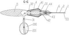
图2-1是图2的G-G剖视图。FIG. 2-1 is a G-G sectional view of FIG. 2 .
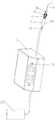
图3是放置储水容器的本发明之带膜分离机构的眼内镊的结构示意图。FIG. 3 is a schematic structural diagram of the intraocular forceps with membrane separation mechanism of the present invention placed in a water storage container.
图4是含电动液体膜分离机构的本发明之带膜分离机构的眼内镊的结构示意图。4 is a schematic structural diagram of an intraocular forceps with a membrane separation mechanism of the present invention including an electrodynamic liquid membrane separation mechanism.
图5是蠕动泵增压的电动液体膜分离机构的结构示意图。FIG. 5 is a schematic structural diagram of an electric liquid membrane separation mechanism pressurized by a peristaltic pump.
图5-1是图5的内部结构示意图。FIG. 5-1 is a schematic diagram of the internal structure of FIG. 5 .
图6是电动空气增压的电动液体膜分离机构的结构示意图。FIG. 6 is a schematic structural diagram of an electric liquid membrane separation mechanism for electric air boosting.
图6-1是图6的内部结构示意图。FIG. 6-1 is a schematic diagram of the internal structure of FIG. 6 .
图7是电动活塞增压的电动液体膜分离机构的结构示意图。FIG. 7 is a schematic structural diagram of an electric liquid film separation mechanism with electric piston pressurization.
图7-1是图7的内部结构示意图。FIG. 7-1 is a schematic diagram of the internal structure of FIG. 7 .
上述图中:In the above picture:
100为本发明之带膜分离机构的眼内镊,200为液源,201为储水球囊,202为储水容器,301为液体膜分离机构。100 is an intraocular forceps with a membrane separation mechanism of the present invention, 200 is a liquid source, 201 is a water storage balloon, 202 is a water storage container, and 301 is a liquid membrane separation mechanism.
1为工作部,2为连接机构,3为膜分离机构,4为控制机构,5为手柄,6为鞘管,7为水密封机构。1 is the working part, 2 is the connection mechanism, 3 is the membrane separation mechanism, 4 is the control mechanism, 5 is the handle, 6 is the sheath tube, and 7 is the water sealing mechanism.
3-1为手动液体膜分离机构,3-2为电动液体膜分离机构3-1,4-1为连杆式控制机构。3-1 is a manual liquid film separation mechanism, 3-2 is an electric liquid film separation mechanism 3-1, and 4-1 is a link-type control mechanism.
31为进水口,32为水通道,33为喷水口,34为液体开关,35为电路及控制系统,36为蠕动泵,37为水箱,38为增压装置,41为控制开关,42为控制芯杆,43为连接座,44为复位弹簧,51为壳体,61为端部,71为密封圈,72为粘胶密封;37-1为活动式底座,38-1为电动空气增压装置,38-2为电动活塞增压装置;38-11为进风口,38-12为充气管,38-13为压缩机;38-21为电机,38-22为推杆。31 is the water inlet, 32 is the water channel, 33 is the water spout, 34 is the liquid switch, 35 is the circuit and control system, 36 is the peristaltic pump, 37 is the water tank, 38 is the booster device, 41 is the control switch, 42 is the Control core rod, 43 is the connecting seat, 44 is the return spring, 51 is the shell, 61 is the end, 71 is the sealing ring, 72 is the adhesive seal; 37-1 is the movable base, 38-1 is the electric air booster. 38-2 is the electric piston pressurizing device; 38-11 is the air inlet, 38-12 is the charging pipe, 38-13 is the compressor; 38-21 is the motor, and 38-22 is the push rod.
具体实施方式Detailed ways
实施例1:带储水球囊的本发明之带膜分离机构的眼内镊Example 1: Intraocular forceps with membrane separation mechanism of the present invention with a water storage balloon
参考图1至图2-1,本实施例之带膜分离机构的眼内镊,含工作部1、连接机构2、膜分离机构3、控制机构4和手柄5。Referring to FIGS. 1 to 2-1 , the intraocular forceps with membrane separation mechanism of this embodiment includes a working part 1 , a
所述连接机构2的远端设有所述工作部1;所述连接机构2的近端设有所述手柄5;The distal end of the
所述控制机构4控制所述工作部1的张开或闭合;The
所述膜分离机构3能实现眼内膜组织的分离,所述工作部1将分离后的眼内膜组织进行钳夹剥离。The
本实施例中,所述膜分离机构3是液体膜分离机构301。所述液体膜分离机构301以液体作为组织膜分离的动力源,利用液体的流动性和冲刷力,所述液体膜分离机构301能非常好地将需要剥离的膜组织和基底组织之间分离,即使是非常狭窄的位置,利用液体的流动性也能方便地到达。In this embodiment, the
所述液体膜分离机构301含进水口31、水通道32及喷水口33,所述进水口31与液源200连通,在压力作用下,液体经所述进水口31进入所述水通道32后经所述喷水口33流出,所述喷水口33流出的液体冲刷眼内膜组织的结合部,分离眼内膜组织。所述液源200的液体可以被施压后从所述喷水口33喷出,在压力作用下,喷出的液体具有更好地冲击力,能够更好地对眼内膜组织进行分离。The liquid membrane separation mechanism 301 includes a
参考图1-1和图1-5,所述喷水口31设置在所述工作部1的近端,当所述工作部1张开时,所述喷水口33流出的液体在所述工作部1呈水帘状;当所述工作部1闭合时,所述喷水口33流出的液体在所述工作部1呈水柱状。当液体呈水帘状时,可以大面积快速地对膜组织进行冲刷和分离,当液体呈水柱状时,可以对局部难分离位置进行精准定点冲击、分离。临床使用时,可以根据需要选用液体的冲刷状态。Referring to FIGS. 1-1 and 1-5 , the
参考图1-3和图1-7,通过调节所述控制机构4可以控制所述工作部1的张开程度从而改变所述喷水口33流出的液体形成的水帘状水流的宽度。所述控制机构4可以控制所述工作部1的张开和闭合,临床使用中,根据需要分离的部位的形状选择水帘的宽度。Referring to FIGS. 1-3 and 1-7 , by adjusting the
参考图1-1和图1-5,本实施例中,所述控制机构4是连杆式控制机构4-1;所述连杆式控制机构4-1含控制开关41,按压所述控制开关41,所述连接机构2向后运动,所述工作部1闭合,松开所述控制开关41,所述连接机构2复位,所述工作部1张开。1-1 and 1-5, in this embodiment, the
参考图1-1、图1-2、图1-5和图1-6,所述连杆式控制机构4-1含控制开关41、控制芯杆42、连接座43、复位弹簧44;所述控制芯杆42和所述连接座43连接,所述复位弹簧44设置在所述连接座43的外侧;所述控制芯杆42、连接座43和复位弹簧44设置在所述手柄5的壳体51内,所述控制开关41设置在所述壳体51的外侧,所述壳体51的远端设有鞘管6,所述连接机构2设置在鞘管6内,所述连接机构2的近端连接在所述连接座43上;按压所述控制开关41,所述控制芯杆42向后运动,带动所述连接座43向后运动,所述复位弹簧44压缩,从而使得所述连接机构2向后运动,连接在所述连接机构2远端的工作部1随之回退,进入所述鞘管6内,所述工作部闭合;松开所述控制开关41,在所述复位弹簧44的回复力作用下,所述连接座43向前运动,连接在所述连接座43上的所述连接机构2带动所述工作部1向前运动,所述工作部1从所述鞘管6远端伸出,所述工作部1张开。1-1, 1-2, 1-5 and 1-6, the link-type control mechanism 4-1 includes a control switch 41, a control core rod 42, a connecting seat 43, and a return spring 44; The control core rod 42 is connected with the connection seat 43, and the return spring 44 is arranged on the outer side of the connection base 43; the control core rod 42, the connection base 43 and the return spring 44 are arranged on the shell of the handle 5 Inside the body 51, the control switch 41 is arranged on the outer side of the casing 51, the distal end of the casing 51 is provided with a sheath 6, the connecting mechanism 2 is arranged in the sheath 6, and the connecting mechanism 2 The proximal end is connected to the connecting seat 43; pressing the control switch 41, the control core rod 42 moves backward, driving the connecting seat 43 to move backward, and the return spring 44 compresses, so that the The connecting mechanism 2 moves backward, and the working part 1 connected to the distal end of the connecting mechanism 2 retreats accordingly and enters the sheath 6, and the working part is closed; Under the action of the restoring force of the return spring 44, the connecting seat 43 moves forward, and the connecting mechanism 2 connected to the connecting seat 43 drives the working part 1 to move forward, and the working part 1 moves forward from the The distal end of the sheath tube 6 is extended, and the working part 1 is opened.
为保证所述控制机构4在控制所述工作部1的开启和闭合的过程中,液体仅能沿所述水通道32流动,设有水密封机构7,本实施例中,在所述壳体5的前端和后端的连接部位设有密封圈71,在所述鞘管6和所述壳体5的连接部位设有粘胶密封72,保证按压所述控制开关41时,所述控制芯杆42运动的过程中,所述壳体5的前端和后端之间仍处于密封状态,不会出现液体的溢出,且液体从所述壳体5内的水通道32流出后仅能经所述鞘管6内的所述水通道32流至所述喷水口33喷出。In order to ensure that the
所述控制机构4还可以是铰链式控制机构、或旋转式控制机构,本领域的技术人员也可以根据需要设计出不同作用形式的所述控制机构4,申请人在此不一一举例说明,但都并不脱离本申请的保护范围。The
本实施例中,所述鞘管6的通孔61构成所述水通道32。In this embodiment, the through
参考图1-1和图1-5,所述鞘管6一方面构成所述水通道32,液体经所述鞘管6排入眼内,另一方面所述鞘管6的端部61能控制所述工作部1的开口程度,随着所述控制芯杆42带动所述工作部1向所述鞘管6内回缩,所述工作部1逐渐闭合。1-1 and 1-5, on the one hand, the
本实施例中,所述液体膜分离机构301是手动液体膜分离机构3-1。In this embodiment, the liquid membrane separation mechanism 301 is a manual liquid membrane separation mechanism 3-1.
所述手动液体膜分离机构3-1含进水口31、水通道32和喷水口33。The manual liquid membrane separation mechanism 3 - 1 includes a
参考图2和图2-1,本实施中,所述液源200是弹性材料制造的储水球囊201;所述进水口31设置在所述水通道32的近端,与所述储水球囊201连通,所述喷水口33设置在所述工作部1的近端,按压所述储水球囊201,所述储水球囊201里的液体被压迫后经所述进水口31进入所述水通道32,后经所述喷水口33排入眼内,对眼内膜组织进行冲刷分离。2 and 2-1, in this embodiment, the
所述储水球囊201设置成手握式,在临床应用中通过按压所述储水球囊201就可以将液体压出,不需要单独设置开关机构,结构简单,操作非常方便。The
当然,也可以单独设置液体开关34,尤其是当所述储水球囊201采用非弹性材料制造时,可以通过控制所述液体开关34来实现所述储水球囊201中液体的排出。Of course, the
临床使用时,先闭合所述工作部1,然后按压所述储水球囊201,所述储水球囊201中的液体呈水柱状对眼内膜组织的薄弱处进行冲洗,形成眼内膜组织钳夹剥离的缺口,然后再张开所述工作部1,液体在所述工作部1的开口处呈水帘状对眼内膜组织进行冲刷,将眼内膜组织和基底组织分离,然后用所述工作部1将分离后的眼内膜组织从基底组织上钳夹剥离。由于液体的冲刷力和流动性,即使是非常微小或狭窄的部位,所述液体膜分离机构301也能将眼内膜组织进行分离。由于眼内膜组织已经和基底组织分离,因此,所述工作部1钳夹剥离时不容易损伤基底组织,不容易造成出血等情况,临床使用更加安全。实施例2:悬挂储水容器的本发明之带膜分离机构的眼内镊In clinical use, the working part 1 is closed first, and then the
参考图3,本实施例与实施例1的区别在于,本实施例中,所述液源200是放置在高处的储水容器202。Referring to FIG. 3 , the difference between this embodiment and Embodiment 1 is that, in this embodiment, the
所述手动液体膜分离机构3-1含进水口31、水通道32、喷水口33和液体开关34。所述进水口31设置在所述水通道32的近端,与所述储水容器202连通,所述喷水口33设置在所述工作部1的近端,所述液体开关34设置在所述手柄5上。The manual liquid membrane separation mechanism 3 - 1 includes a
放置在高处的所述储水容器202提供液体的流动动力,所述液体开关34可以控制液体的流出和关闭。通过调节所述储水容器202放置的高度,可以方便地调节液体的压力,临床使用非常方便。The
临床使用时,根据压力需要,将所述储水容器202放置至合适的高度,给液体提供合适的压力,手术时,先闭合所述工作部1,打开所述液体开关34,所述储水容器202中的液体呈水柱状对眼内膜组织的薄弱处进行冲洗,形成眼内膜组织钳夹剥离的缺口,然后再张开所述工作部1,液体在所述工作部1的开口处呈水帘状对眼内膜组织进行冲刷,将眼内膜组织和基底组织分离,然后关闭所述液体开关34,用所述工作部1将分离后的眼内膜组织从基底组织上钳夹剥离。In clinical use, according to pressure requirements, the
本实施例之带膜分离机构的眼内镊,通过调整所述储水容器202的放置高度就可以很方便的调节液体的压力,临床应用中,当需要进行眼内膜分离时,打开所述液体开关34即可对眼内膜组织进行分离,临床应用非常方便。In the intraocular forceps with membrane separation mechanism of this embodiment, the pressure of the liquid can be easily adjusted by adjusting the placement height of the
实施例3:电动的本发明之带膜分离机构的眼内镊Example 3: Electric intraocular forceps with membrane separation mechanism of the present invention
参考图4至图7-1,本实施例与实施例1的区别在于,本实施例中,所述带膜分离机构的眼内镊100的液体膜分离机构301是电动液体膜分离机构3-2。4 to 7-1, the difference between this embodiment and Embodiment 1 is that in this embodiment, the liquid film separation mechanism 301 of the
所述电动液体膜分离机构3-2可以采用蠕动泵的方式对液体进行吸引和增压。The electric liquid membrane separation mechanism 3-2 can use a peristaltic pump to attract and pressurize the liquid.
参考图4至图5-1,所述电动液体膜分离机构3-2含进水口31、水通道32、喷水口33、液体开关34、电路及控制系统35、蠕动泵36及水箱37;所述蠕动泵36一端与所述水箱37连接,另一端与液源200连接;在所述电路及控制系统35的作用下,所述蠕动泵36工作,所述液源200中的液体被吸入所述水箱37内,打开所述液体开关34,所述水箱内37中的液体经进水口31经所述水通道32后从所述喷水口33排入眼内,对眼内膜组织进行冲刷分离。所述电路及控制系统35可以控制所述蠕动泵36的工作,所述蠕动泵36可以精确地控制液体的流量和速度。4 to 5-1, the electric liquid membrane separation mechanism 3-2 includes a
所述电动液体膜分离机构3-2还可以采取增压装置对液体进行增压。The electric liquid membrane separation mechanism 3-2 may also adopt a pressurizing device to pressurize the liquid.
参考图6至图7-1,所述电动液体膜分离机构3-2含进水口31、水通道32、液体开关34、电路及控制系统35、增压装置38及水箱37。6 to 7-1 , the electric liquid membrane separation mechanism 3-2 includes a
所述增压装置38是电动空气增压装置38-1或电动活塞增压装置38-2。The supercharging device 38 is an electric air supercharging device 38-1 or an electric piston supercharging device 38-2.
参考图6和图6-1,所述增压装置38是电动空气增压装置38-1;所述电动空气增压装置38-1含进风口38-11、充气管38-12和压缩机38-13,所述压缩机38-13工作时,空气经所述进风口38-11进入所述充气管38-12对所述水箱37内的液体进行增压,液体经增压后从所述进水口31进入所述水通道32,经所述喷水口33排入眼内,对眼内膜组织进行冲刷分离。6 and 6-1, the supercharging device 38 is an electric air supercharging device 38-1; the electric air supercharging device 38-1 includes an air inlet 38-11, a charging pipe 38-12 and a compressor 38-13, when the compressor 38-13 is working, the air enters the inflation pipe 38-12 through the air inlet 38-11 to pressurize the liquid in the
参考图7和图7-1,所述增压装置38是所述电动活塞增压装置38-2;所述电动活塞增压装置38-2含电机38-21、推杆38-22,所述水箱37含活动式底座37-1;在所述电路及控制系统35作用下,所述电机38-21工作,所述推杆38-22推动所述活动式底座37-1运动,所述水箱37里的液体在压力作用下进入所述水通道32,经所述喷水口33排入眼内,对眼内膜组织进行冲刷分离。7 and 7-1, the booster device 38 is the electric piston booster device 38-2; the electric piston booster device 38-2 includes a motor 38-21 and a push rod 38-22. The
所述增压装置38能精确控制膜分离用液体的压力,并在显示界面上进行压力的实时显示。The pressurizing device 38 can precisely control the pressure of the liquid for membrane separation, and display the pressure in real time on the display interface.
申请人在此只列举了以上三种电动液体膜分离机构的设计方案,本领域的技术人员还可以根据需要设计出不同的所述电动液体膜分离机构3-2来实现膜分离过程的液体的电动精确控制,申请人在此不一一举例说明,但都不脱离本申请的保护范围。The applicant has only listed the above three design schemes of the electric liquid membrane separation mechanism, and those skilled in the art can also design different electric liquid membrane separation mechanisms 3-2 as required to realize the liquid separation of the membrane separation process. The electric precise control, the applicant will not give examples here, but will not depart from the protection scope of the present application.
临床使用时,先开启所述电路及控制系统35,所述液源200中的液体被增压、吸入所述水箱37内,手术过程中,当需要对眼内膜组织进行分离时,开启所述液体开关34,液体经所述进水口31进入本发明之带膜分离机构的眼内镊的水通道32内,并经所述喷水口33排入眼内,对眼内膜组织进行分离,然后再用所述工作部1将分离后的膜组织钳夹剥离。In clinical use, the circuit and the
由于所述电动液体膜分离机构3-2可以对液体的压力、流量和流速进行精确控制,并可以在控制界面上进行实时显示,因此,临床应用过程可以实现膜分离过程中液体的精确定量控制。Since the electric liquid membrane separation mechanism 3-2 can precisely control the pressure, flow and flow rate of the liquid, and can display it in real time on the control interface, the clinical application process can realize the precise quantitative control of the liquid in the membrane separation process .
应该注意,本文中公开和说明的结构可以用其它效果相同的结构代替,同时本发明所介绍的实施例并非实现本发明的唯一结构。虽然本发明的优先实施例已在本文中予以介绍和说明,但本领域内的技术人员都清楚知道这些实施例不过是举例说明而己,本领域内的技术人员可以做出无数的变化、改进和代替,而不会脱离本发明,因此,应按照本发明所附的权利要求书的精神和范围来的界定本发明的保护范围。It should be noted that the structures disclosed and described herein may be replaced by other structures having the same effect, and the described embodiments of the present invention are not the only structures for implementing the present invention. Although preferred embodiments of the present invention have been introduced and illustrated herein, those skilled in the art will clearly understand that these embodiments are merely illustrative and that numerous changes and improvements can be made by those skilled in the art Instead, without departing from the present invention, the protection scope of the present invention should be defined in accordance with the spirit and scope of the appended claims of the present invention.
Claims (20)
Translated fromChinesePriority Applications (2)
| Application Number | Priority Date | Filing Date | Title |
|---|---|---|---|
| CN202110028298.7ACN114748241A (en) | 2021-01-09 | 2021-01-09 | Intraocular forceps with membrane separation mechanism |
| PCT/CN2022/070484WO2022148393A1 (en) | 2021-01-09 | 2022-01-06 | Intraocular forceps having membrane separation mechanism |
Applications Claiming Priority (1)
| Application Number | Priority Date | Filing Date | Title |
|---|---|---|---|
| CN202110028298.7ACN114748241A (en) | 2021-01-09 | 2021-01-09 | Intraocular forceps with membrane separation mechanism |
Publications (1)
| Publication Number | Publication Date |
|---|---|
| CN114748241Atrue CN114748241A (en) | 2022-07-15 |
Family
ID=82325639
Family Applications (1)
| Application Number | Title | Priority Date | Filing Date |
|---|---|---|---|
| CN202110028298.7APendingCN114748241A (en) | 2021-01-09 | 2021-01-09 | Intraocular forceps with membrane separation mechanism |
Country Status (2)
| Country | Link |
|---|---|
| CN (1) | CN114748241A (en) |
| WO (1) | WO2022148393A1 (en) |
Cited By (3)
| Publication number | Priority date | Publication date | Assignee | Title |
|---|---|---|---|---|
| CN115106170A (en)* | 2021-03-18 | 2022-09-27 | 深圳市眼科医院 | Intraocular tissue disruptor |
| CN115944459A (en)* | 2022-12-30 | 2023-04-11 | 爱尔眼科医院集团四川眼科医院有限公司 | Ophthalmic tweezers for microscopic fundus surgery |
| CN116942412A (en)* | 2023-09-21 | 2023-10-27 | 杭州爱尔眼科医院有限公司 | Be used for glaucoma operation room angle separation tweezers |
Family Cites Families (8)
| Publication number | Priority date | Publication date | Assignee | Title |
|---|---|---|---|---|
| CN1761436A (en)* | 2002-12-10 | 2006-04-19 | 视锐有限公司 | Disposable separator for separating the epithelium layer from the cornea of an eye |
| US20040260321A1 (en)* | 2002-12-19 | 2004-12-23 | Ming-Kok Tai | Apparatus and method for separating the epithelium layer from the cornea of an eye without corneal pre-applanation |
| DE202005018601U1 (en)* | 2005-11-29 | 2006-04-13 | Human Med Ag | Surgical device for separating a biological structure by means of a liquid jet |
| US8187293B2 (en)* | 2006-02-06 | 2012-05-29 | Novartis Ag | Microsurgical instrument |
| US8206349B2 (en)* | 2007-03-01 | 2012-06-26 | Medtronic Xomed, Inc. | Systems and methods for biofilm removal, including a biofilm removal endoscope for use therewith |
| WO2012158516A2 (en)* | 2011-05-13 | 2012-11-22 | Vascular Technology Inc. | Remotely controlled suction/irrigation for surgery |
| US9320534B2 (en)* | 2012-12-13 | 2016-04-26 | Alcon Research, Ltd. | Fine membrane forceps with integral scraping feature |
| US11224539B2 (en)* | 2017-06-28 | 2022-01-18 | Alcon Inc. | Coated forceps for improved grasping |
- 2021
- 2021-01-09CNCN202110028298.7Apatent/CN114748241A/enactivePending
- 2022
- 2022-01-06WOPCT/CN2022/070484patent/WO2022148393A1/ennot_activeCeased
Cited By (4)
| Publication number | Priority date | Publication date | Assignee | Title |
|---|---|---|---|---|
| CN115106170A (en)* | 2021-03-18 | 2022-09-27 | 深圳市眼科医院 | Intraocular tissue disruptor |
| CN115944459A (en)* | 2022-12-30 | 2023-04-11 | 爱尔眼科医院集团四川眼科医院有限公司 | Ophthalmic tweezers for microscopic fundus surgery |
| CN116942412A (en)* | 2023-09-21 | 2023-10-27 | 杭州爱尔眼科医院有限公司 | Be used for glaucoma operation room angle separation tweezers |
| CN116942412B (en)* | 2023-09-21 | 2023-12-12 | 杭州爱尔眼科医院有限公司 | Be used for glaucoma operation room angle separation tweezers |
Also Published As
| Publication number | Publication date |
|---|---|
| WO2022148393A1 (en) | 2022-07-14 |
Similar Documents
| Publication | Publication Date | Title |
|---|---|---|
| WO2022148393A1 (en) | Intraocular forceps having membrane separation mechanism | |
| JP4344109B2 (en) | Colostomy pump device | |
| CN101454038B (en) | A device that enlarges a vein using a vacuum ready for insertion of a needle or cannula | |
| JPH1119116A (en) | Surgical operation device | |
| CA2617036A1 (en) | Irrigation/aspiration tip | |
| CN109789034B (en) | System for performing phacoemulsification | |
| EP2014266B1 (en) | Method of priming a surgical system | |
| KR20220004080A (en) | Medical Ophthalmic Devices | |
| CN106510945A (en) | Auditory meatus cleaning device | |
| AU2021359289A1 (en) | Vacuum-assisted forceps for ophthalmic procedures | |
| CN216091024U (en) | Intraocular forceps with membrane separation mechanism | |
| CN113456159A (en) | Blood flow blocking ring and quick blood flow blocking device for general surgery department operation | |
| CN217013980U (en) | Gastrointestinal endoscope with function of removing blood clots | |
| CN109350353B (en) | Device for sucking and removing posterior chamber viscoelastic agent for central hole type artificial lens implantation and use method | |
| CN214907450U (en) | An endoscope breast retractor | |
| CN112618337B (en) | Nasal cavity cleaner is used in general medical treatment | |
| CN201389212Y (en) | Nasal cavity foreign cleaning device | |
| CN204671102U (en) | A kind of nerve endoscope flusher | |
| CN209450628U (en) | Multi-functional closed hydatid cyst stripper for laparoscopy | |
| CN111772750A (en) | An obstetric membrane rupture device | |
| KR200409983Y1 (en) | Hand pump | |
| CN218451642U (en) | A Suctionable Injectable Ophthalmic Capsulorhexis Forceps | |
| CN113521423B (en) | Independent milk duct perfusion assembly and use method thereof | |
| CN215351122U (en) | Nasopharynx washing unit is used in oncology nursing | |
| CN222604670U (en) | Medical endoscope with integrated expansion and suction functions |
Legal Events
| Date | Code | Title | Description |
|---|---|---|---|
| PB01 | Publication | ||
| PB01 | Publication | ||
| SE01 | Entry into force of request for substantive examination | ||
| SE01 | Entry into force of request for substantive examination |