CN114748156A - Electrode assemblies, ablation devices, and radiofrequency ablation devices - Google Patents
Electrode assemblies, ablation devices, and radiofrequency ablation devicesDownload PDFInfo
- Publication number
- CN114748156A CN114748156ACN202110026567.6ACN202110026567ACN114748156ACN 114748156 ACN114748156 ACN 114748156ACN 202110026567 ACN202110026567 ACN 202110026567ACN 114748156 ACN114748156 ACN 114748156A
- Authority
- CN
- China
- Prior art keywords
- electrode
- protective sheath
- electrodes
- ablation
- electrode assembly
- Prior art date
- Legal status (The legal status is an assumption and is not a legal conclusion. Google has not performed a legal analysis and makes no representation as to the accuracy of the status listed.)
- Granted
Links
Images


Classifications
- A—HUMAN NECESSITIES
- A61—MEDICAL OR VETERINARY SCIENCE; HYGIENE
- A61B—DIAGNOSIS; SURGERY; IDENTIFICATION
- A61B18/00—Surgical instruments, devices or methods for transferring non-mechanical forms of energy to or from the body
- A61B18/04—Surgical instruments, devices or methods for transferring non-mechanical forms of energy to or from the body by heating
- A61B18/12—Surgical instruments, devices or methods for transferring non-mechanical forms of energy to or from the body by heating by passing a current through the tissue to be heated, e.g. high-frequency current
- A61B18/14—Probes or electrodes therefor
- A—HUMAN NECESSITIES
- A61—MEDICAL OR VETERINARY SCIENCE; HYGIENE
- A61B—DIAGNOSIS; SURGERY; IDENTIFICATION
- A61B18/00—Surgical instruments, devices or methods for transferring non-mechanical forms of energy to or from the body
- A61B2018/00315—Surgical instruments, devices or methods for transferring non-mechanical forms of energy to or from the body for treatment of particular body parts
- A61B2018/00345—Vascular system
- A61B2018/00351—Heart
- A61B2018/00357—Endocardium
- A—HUMAN NECESSITIES
- A61—MEDICAL OR VETERINARY SCIENCE; HYGIENE
- A61B—DIAGNOSIS; SURGERY; IDENTIFICATION
- A61B18/00—Surgical instruments, devices or methods for transferring non-mechanical forms of energy to or from the body
- A61B2018/00315—Surgical instruments, devices or methods for transferring non-mechanical forms of energy to or from the body for treatment of particular body parts
- A61B2018/00345—Vascular system
- A61B2018/00351—Heart
- A61B2018/00363—Epicardium
- A—HUMAN NECESSITIES
- A61—MEDICAL OR VETERINARY SCIENCE; HYGIENE
- A61B—DIAGNOSIS; SURGERY; IDENTIFICATION
- A61B18/00—Surgical instruments, devices or methods for transferring non-mechanical forms of energy to or from the body
- A61B2018/00571—Surgical instruments, devices or methods for transferring non-mechanical forms of energy to or from the body for achieving a particular surgical effect
- A61B2018/00577—Ablation
- A—HUMAN NECESSITIES
- A61—MEDICAL OR VETERINARY SCIENCE; HYGIENE
- A61B—DIAGNOSIS; SURGERY; IDENTIFICATION
- A61B18/00—Surgical instruments, devices or methods for transferring non-mechanical forms of energy to or from the body
- A61B2018/00636—Sensing and controlling the application of energy
- A61B2018/00696—Controlled or regulated parameters
- A61B2018/00702—Power or energy
- A61B2018/00708—Power or energy switching the power on or off
- A—HUMAN NECESSITIES
- A61—MEDICAL OR VETERINARY SCIENCE; HYGIENE
- A61B—DIAGNOSIS; SURGERY; IDENTIFICATION
- A61B18/00—Surgical instruments, devices or methods for transferring non-mechanical forms of energy to or from the body
- A61B2018/00636—Sensing and controlling the application of energy
- A61B2018/00773—Sensed parameters
- A61B2018/00875—Resistance or impedance
- A—HUMAN NECESSITIES
- A61—MEDICAL OR VETERINARY SCIENCE; HYGIENE
- A61B—DIAGNOSIS; SURGERY; IDENTIFICATION
- A61B18/00—Surgical instruments, devices or methods for transferring non-mechanical forms of energy to or from the body
- A61B18/04—Surgical instruments, devices or methods for transferring non-mechanical forms of energy to or from the body by heating
- A61B18/12—Surgical instruments, devices or methods for transferring non-mechanical forms of energy to or from the body by heating by passing a current through the tissue to be heated, e.g. high-frequency current
- A61B18/14—Probes or electrodes therefor
- A61B2018/1405—Electrodes having a specific shape
Landscapes
- Health & Medical Sciences (AREA)
- Surgery (AREA)
- Engineering & Computer Science (AREA)
- Life Sciences & Earth Sciences (AREA)
- Biomedical Technology (AREA)
- Otolaryngology (AREA)
- Nuclear Medicine, Radiotherapy & Molecular Imaging (AREA)
- Plasma & Fusion (AREA)
- Physics & Mathematics (AREA)
- Heart & Thoracic Surgery (AREA)
- Medical Informatics (AREA)
- Molecular Biology (AREA)
- Animal Behavior & Ethology (AREA)
- General Health & Medical Sciences (AREA)
- Public Health (AREA)
- Veterinary Medicine (AREA)
- Surgical Instruments (AREA)
Abstract
Translated fromChinese
Description
Translated fromChinese技术领域technical field
本发明涉及医疗器械领域,具体而言,涉及一种电极组件、消融装置和射频消融设备。The present invention relates to the field of medical devices, in particular, to an electrode assembly, an ablation device and a radiofrequency ablation device.
背景技术Background technique
消融是治疗房颤的常见措施,其原理是在心脏组织创建一条或多条消融线,引起组织坏死,切断不正常的电信号传导,用于房颤的治疗。Ablation is a common measure for the treatment of atrial fibrillation. The principle is to create one or more ablation lines in the heart tissue, causing tissue necrosis and cutting off abnormal electrical signal conduction for the treatment of atrial fibrillation.
当前的消融治疗分为外科消融和内科介入消融,外科消融的特点是疗效优,术后复发率低,但是其显而易见的缺点是创伤较大,术后恢复慢。内科的介入式消融因为创伤小、恢复快受到越来越多患者的青睐,但是内科消融是点状消融,其最大的弊端便是很难形成一条完整的消融线;且消融时是单侧贴壁式工作,消融深度有限,很难保证组织由内至外完全脱水、变性,手术中消融功率小时消融不彻底,而功率大了又不易掌控,有消融过度组织坏死甚至烧穿、烧漏现象,故内科介入式消融的成功率较外科低好多。The current ablation treatment is divided into surgical ablation and medical interventional ablation. Surgical ablation is characterized by excellent curative effect and low postoperative recurrence rate, but its obvious shortcomings are large trauma and slow postoperative recovery. Medical interventional ablation is favored by more and more patients because of its small trauma and fast recovery, but medical ablation is point ablation, and its biggest drawback is that it is difficult to form a complete ablation line; Wall work, the ablation depth is limited, and it is difficult to ensure complete dehydration and degeneration of the tissue from the inside to the outside. During the operation, the ablation power is small and the ablation is not complete, but the power is high and it is difficult to control. There are excessive ablation tissue necrosis or even burning through and burning leakage. Therefore, the success rate of medical interventional ablation is much lower than that of surgery.
发明内容SUMMARY OF THE INVENTION
本发明的主要目的在于提供一种电极组件、消融装置和射频消融设备,以解决现有技术中的消融装置与待消融组织贴合不牢固,容易脱开待消融组织且消融效果不理想的问题。The main purpose of the present invention is to provide an electrode assembly, an ablation device and a radio frequency ablation device, so as to solve the problems in the prior art that the ablation device is not firmly attached to the tissue to be ablated, the tissue to be ablated is easily detached, and the ablation effect is unsatisfactory .
为了实现上述目的,根据本发明的一个方面,提供了一种电极组件,其包括电极端头,该电极端头包括:保护鞘;电极,电极设置在保护鞘内;填充件,填充件设置在保护鞘内,以通过填充件将保护鞘内的电极朝向待消融组织挤压。In order to achieve the above object, according to an aspect of the present invention, an electrode assembly is provided, which includes an electrode tip, and the electrode tip includes: a protective sheath; an electrode, the electrode is arranged in the protective sheath; a filler, the filler is arranged in the protective sheath Inside the protective sheath to squeeze the electrodes in the protective sheath toward the tissue to be ablated through the filler.
进一步地,电极为多个,保护鞘为条形,多个电极沿保护鞘的延伸方向间隔布置。Further, there are a plurality of electrodes, the protective sheath is strip-shaped, and the plurality of electrodes are arranged at intervals along the extending direction of the protective sheath.
进一步地,填充件为条形,保护鞘为条形,填充件沿保护鞘的延伸方向延伸。Further, the filler is in the shape of a bar, the protective sheath is in the shape of a bar, and the filler extends along the extension direction of the protective sheath.
进一步地,填充件为多个,保护鞘为条形,多个填充件沿保护鞘的延伸方向间隔布置。Further, there are a plurality of fillers, the protective sheath is strip-shaped, and the plurality of fillers are arranged at intervals along the extending direction of the protective sheath.
进一步地,多个填充件和多个电极一一对应地设置,各个填充件均设置在相应的电极的远离待消融组织的一侧。Further, a plurality of fillers and a plurality of electrodes are arranged in a one-to-one correspondence, and each filler is arranged on a side of the corresponding electrode away from the tissue to be ablated.
进一步地,多个电极的通电电路独立设置,以单独控制各个电极。Further, the energization circuits of the plurality of electrodes are provided independently, so as to individually control each electrode.
进一步地,多个填充件的通气管路独立设置,以单独控制各个填充件的充气状态。Further, the ventilation pipelines of the plurality of fillers are independently arranged, so as to individually control the inflation state of each filler.
进一步地,填充件为气囊结构。Further, the filler is an airbag structure.
进一步地,保护鞘上设置有用于避让电极的开孔结构,以使电极的部分结构经开孔结构由保护鞘的腔体伸出。Further, the protective sheath is provided with an opening structure for avoiding the electrode, so that part of the electrode structure protrudes from the cavity of the protective sheath through the opening structure.
进一步地,电极为多个,开孔结构包括多个避让开孔,多个避让开孔与多个电极一一对应地设置,以使各个电极的部分结构通过相应的避让开孔伸出至保护鞘的外侧。Further, there are a plurality of electrodes, the opening structure includes a plurality of avoidance openings, and the plurality of avoidance openings are arranged in a one-to-one correspondence with the plurality of electrodes, so that part of the structure of each electrode extends to the protection through the corresponding avoidance openings. outside of the sheath.
进一步地,电极为多个,开孔结构为条形开口,条形开口沿保护鞘的延伸方向间隔,多个电极的部分结构通过条形开口伸出至保护鞘的外侧。Further, there are a plurality of electrodes, the opening structure is a strip-shaped opening, the strip-shaped openings are spaced along the extending direction of the protective sheath, and part of the structure of the plurality of electrodes extends to the outside of the protective sheath through the strip-shaped openings.
根据本发明的另一方面,提供了一种消融装置,其包括第一电极组件和第二电极组件,第一电极组件位上述的电极组件,第一电极组件的电极为第一电极,第二电极组件包括第二电极端头,第二电极端头包括第二电极,第二电极与第一电极相对设置,以通过第一电极和第二电极对位于第一电极和第二电极之间的待消融组织进行消融。According to another aspect of the present invention, an ablation device is provided, which includes a first electrode assembly and a second electrode assembly, the first electrode assembly is located in the above-mentioned electrode assembly, the electrode of the first electrode assembly is the first electrode, and the second electrode assembly is the first electrode. The electrode assembly includes a second electrode tip, the second electrode tip includes a second electrode, and the second electrode is disposed opposite the first electrode so as to pass through the first electrode and the second electrode pair between the first electrode and the second electrode. The tissue to be ablated is ablated.
进一步地,消融装置还包括消融电路,第一电极和第二电极均设置在消融电路上,以通过测试第一电极和相应的第二电极之间的阻抗调整第一电极和第二电极之间的射频能量来进行消融。Further, the ablation device further includes an ablation circuit, and the first electrode and the second electrode are both arranged on the ablation circuit, so as to adjust the impedance between the first electrode and the second electrode by testing the impedance between the first electrode and the corresponding second electrode. radiofrequency energy for ablation.
根据本发明的又一方面,提供了一种射频消融设备,其包括射频主机和上述的消融装置,该消融装置与射频主机连接。According to another aspect of the present invention, a radio frequency ablation apparatus is provided, which includes a radio frequency host and the above-mentioned ablation device, and the ablation device is connected to the radio frequency host.
应用本发明的技术方案,该电极组件包括电极端头,电极端头包括保护鞘以及设置在保护鞘内的电极和填充件,通过填充件对电极进行挤压以使电极朝向待消融组织移动,进而使电极能够与保护鞘的内壁贴合,而相对应的位置的保护鞘的外壁与相应的待消融组织贴合,从而保证电极能够较好地作用于相应的待消融组织,保证消融效果;可见,使用本电极组件能够解决现有技术中的消融装置与待消融组织贴合不牢固,容易脱开待消融组织且消融效果不理想的问题。Applying the technical solution of the present invention, the electrode assembly includes an electrode tip, the electrode tip includes a protective sheath, an electrode and a filler arranged in the protective sheath, and the electrode is squeezed by the filler to move the electrode toward the tissue to be ablated, Then, the electrode can be attached to the inner wall of the protective sheath, and the outer wall of the protective sheath at the corresponding position is attached to the corresponding tissue to be ablated, so as to ensure that the electrode can better act on the corresponding tissue to be ablated and ensure the ablation effect; It can be seen that the use of the electrode assembly can solve the problems in the prior art that the ablation device is not firmly attached to the tissue to be ablated, the tissue to be ablated is easily detached, and the ablation effect is unsatisfactory.
附图说明Description of drawings
构成本申请的一部分的说明书附图用来提供对本发明的进一步理解,本发明的示意性实施例及其说明用于解释本发明,并不构成对本发明的不当限定。在附图中:The accompanying drawings forming a part of the present application are used to provide further understanding of the present invention, and the exemplary embodiments of the present invention and their descriptions are used to explain the present invention and do not constitute an improper limitation of the present invention. In the attached image:
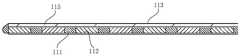
图1示出了根据本发明的可选的一种电极组件的结构示意图;FIG. 1 shows a schematic structural diagram of an optional electrode assembly according to the present invention;
图2示出了图1中的电极组件的纵向剖视结构图;FIG. 2 shows a longitudinal cross-sectional structural view of the electrode assembly in FIG. 1;
图3示出了图1中的电极组件的具有遮挡侧檐的一种结构设置示意图;FIG. 3 shows a schematic diagram of a structural arrangement of the electrode assembly in FIG. 1 with shielding side eaves;
图4示出了图1中的电极组件的具有遮挡侧檐的另一种结构设置示意图;Fig. 4 is a schematic diagram showing another structural arrangement of the electrode assembly in Fig. 1 with shielding side eaves;
图5示出了图1中的电极组件的具有导线铺设槽的结构设置示意图;FIG. 5 shows a schematic diagram of the structure arrangement of the electrode assembly in FIG. 1 with wire laying grooves;
图6示出了根据本发明的电极组件的另一个实施例的剖视图;Figure 6 shows a cross-sectional view of another embodiment of an electrode assembly according to the present invention;
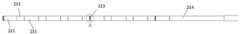
图7示出了根据本发明的可选的一种消融装置的第二电极组件的结构示意图;Fig. 7 shows a schematic structural diagram of a second electrode assembly of an optional ablation device according to the present invention;
图8示出了图7中的消融装置的第二电极组件的局部放大图;FIG. 8 shows a partial enlarged view of the second electrode assembly of the ablation device of FIG. 7;
图9示出了图8中的消融装置的第二电极组件的A部放大图;FIG. 9 shows an enlarged view of part A of the second electrode assembly of the ablation device of FIG. 8;
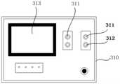
图10示出了根据本发明的可选的一种射频消融设备的射频主机的结构示意图;FIG. 10 shows a schematic structural diagram of a radio frequency host of an optional radio frequency ablation device according to the present invention;
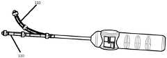
图11示出了根据本发明的可选的一种射频消融设备的射频主机和消融装置之间的组装图;FIG. 11 shows an assembly diagram between a radio frequency host and an ablation device of an optional radio frequency ablation device according to the present invention;
图12示出了本发明中的消融装置对待消融组织进行消融处理时的原理图;Fig. 12 shows the principle diagram of the ablation device in the present invention when the tissue to be ablated is ablated;
图13示出了本发明中的消融装置的一个实施例的第一电极和第二电极与待消融组织之间的配合图;Fig. 13 is a diagram showing the cooperation between the first electrode and the second electrode and the tissue to be ablated in an embodiment of the ablation device of the present invention;
图14示出了本发明的消融装置的一种状态的消融原理图;Fig. 14 shows a schematic diagram of ablation in one state of the ablation device of the present invention;
图15示出了本发明的消融装置的另一种状态的消融原理图;Fig. 15 shows the ablation principle diagram of another state of the ablation device of the present invention;
图16示出了本发明的射频消融设备的射频主机与第一电极组件和第二电极组件之间的接线原理图;16 shows a schematic diagram of the wiring between the radio frequency host and the first electrode assembly and the second electrode assembly of the radio frequency ablation device of the present invention;
图17示出了本发明的消融装置的第一电极组件的第二个实施例的结构示意图;Fig. 17 shows a schematic structural diagram of the second embodiment of the first electrode assembly of the ablation device of the present invention;
图18示出了本发明的消融装置的第二电极组件的第二个实施例的结构示意图;Fig. 18 shows a schematic structural diagram of the second embodiment of the second electrode assembly of the ablation device of the present invention;
图19示出了本发明的消融装置的另一个实施例的第一电极和第二电极与待消融组织之间的配合图。FIG. 19 is a diagram showing the cooperation between the first electrode and the second electrode and the tissue to be ablated in another embodiment of the ablation device of the present invention.
其中,上述附图包括以下附图标记:Wherein, the above-mentioned drawings include the following reference signs:
100、第一电极组件;100. A first electrode assembly;
110、电极端头;111、电极;1110、电极面;1112、冷却孔;112、第一磁性件;113、保护鞘;1130、保护鞘面;115、遮挡侧檐;116、填充件;118、导线;110, electrode tip; 111, electrode; 1110, electrode surface; 1112, cooling hole; 112, first magnetic part; 113, protective sheath; 1130, protective sheath surface; 115, blocking side eaves; 116, filler; ,wire;
120、导线铺设槽;120. Conductor laying groove;
200、第二电极组件;200. A second electrode assembly;
210、第二电极端头;211、第二电极;212、第二磁性件;213、显影件;214、第二保护鞘;210, the second electrode tip; 211, the second electrode; 212, the second magnetic member; 213, the developing member; 214, the second protective sheath;
310、射频主机;311、消融接口;312、电磁接口;313、显示屏;320、消融电路;330、消融范围;340、待消融组织。310, radio frequency host; 311, ablation interface; 312, electromagnetic interface; 313, display screen; 320, ablation circuit; 330, ablation range; 340, tissue to be ablated.
具体实施方式Detailed ways
需要说明的是,在不冲突的情况下,本申请中的实施例及实施例中的特征可以相互组合。下面将参考附图并结合实施例来详细说明本发明。It should be noted that the embodiments in the present application and the features of the embodiments may be combined with each other in the case of no conflict. The present invention will be described in detail below with reference to the accompanying drawings and in conjunction with the embodiments.
本发明提供了一种电极组件,请参考图1至图19,该电极组件包括电极端头110,电极端头110包括保护鞘113、电极111以及填充件116,电极111设置在保护鞘113内;填充件116设置在保护鞘113内,以通过填充件116将保护鞘113内的电极111朝向待消融组织挤压。The present invention provides an electrode assembly, please refer to FIG. 1 to FIG. 19 , the electrode assembly includes an
在本发明的电极组件中,该电极组件包括电极端头110,电极端头110包括保护鞘113以及设置在保护鞘113内的电极111和填充件116,通过填充件116对电极111进行挤压以使电极111朝向待消融组织移动,进而使电极111能够与保护鞘113的内壁贴合,而相对应的位置的保护鞘113的外壁与相应的待消融组织贴合,从而保证电极111能够较好地作用于相应的待消融组织,保证消融效果;可见,使用本电极组件能够解决现有技术中的内科介入式消融装置消融效果不理想的问题。In the electrode assembly of the present invention, the electrode assembly includes an
具体地,电极111为多个,保护鞘113为条形,多个电极111沿保护鞘113的延伸方向间隔布置;即通过多个电极111同时作用于其相对应的待消融组织,以形成一条完整的消融线,保证消融效果、提高消融效率;且使多个电极111间隔布置,可以避免相邻两个电极111之间相互影响。Specifically, there are
可选地,保护鞘113为管状,多个电极111均设置在保护鞘113的管腔内。Optionally, the
在本实施例中,电极111为5至10个。In this embodiment, there are 5 to 10
在本实施例中,填充件116的一种设置方式为:如图2所示,填充件116为条形,保护鞘113为条形,填充件116沿保护鞘113的延伸方向延伸。具体地,填充件116为气囊结构,以在该气囊结构被充气而膨胀时,对多个电极111形成挤压作用。In this embodiment, an arrangement of the filling
在本实施例中,填充件116的另一种设置方式为:填充件116为多个,多个填充件116沿保护鞘113的延伸方向间隔布置;多个填充件116和多个电极111一一对应地设置,以使各个填充件116能够对相应的电极111形成挤压作用;各个填充件116均设置在相应的电极111的远离待消融组织的一侧,以实现各个填充件116对相应的电极111形成挤压作用时,各个电极111朝靠近相应的待消融组织的方向移动。具体地,各个填充件116均为气囊结构,以在该气囊结构被充气而膨胀时,对相应的电极111形成挤压作用。In this embodiment, another arrangement of the
在一些实施例中,多个电极111的通电电路独立设置,以单独控制各个电极111。In some embodiments, the energization circuits of the plurality of
在一些实施例中,两个相邻的第一电极的通电电路独立设置以形成消融电极对,以实现消融功能。In some embodiments, the energization circuits of two adjacent first electrodes are independently arranged to form an ablation electrode pair to achieve an ablation function.
在一些实施例中,多个填充件116的通气管路独立设置,以单独控制各个填充件116的充气状态。In some embodiments, the ventilation lines of the plurality of
具体地,保护鞘113上设置有用于避让电极111的开孔结构,以使电极111的部分结构经开孔结构由保护鞘113的腔体伸出,这样,伸出保护鞘113的腔体的这部分电极结构能够与相应的待消融组织直接接触,进而使这部分电极结构更好地作用于其相应的待消融组织,以进一步保证消融效果、提高消融效率。Specifically, the
在本实施例中,开孔结构的一种设置形式为:当电极111为多个,开孔结构包括多个避让开孔,多个避让开孔与多个电极111一一对应地设置,以使各个电极111的部分结构通过相应的避让开孔伸出至保护鞘113的外侧,进而使伸出保护鞘113外侧的各个电极111的部分结构均能够与相应的待消融组织直接接触。In this embodiment, a setting form of the opening structure is: when there are
在本实施例中,开孔结构的另一种设置形式为:开孔结构为条形开口,条形开口沿保护鞘113的延伸方向间隔,多个电极111的部分结构通过条形开口伸出至保护鞘113的外侧。In this embodiment, another setting form of the opening structure is as follows: the opening structure is a strip-shaped opening, the strip-shaped openings are spaced along the extending direction of the
本发明还提供了一种消融装置,该消融装置包括第一电极组件100和第二电极组件200,第一电极组件100为上述的电极组件,第一电极组件100的电极为第一电极,即第一电极组件100的第一电极端头为电极端头110,第一电极为电极111,第二电极组件200包括第二电极端头210,第二电极端头210包括第二电极211,第二电极211与第一电极相对设置,以通过第一电极和第二电极211对位于第一电极和第二电极211之间的待消融组织进行消融。The present invention also provides an ablation device, the ablation device includes a
具体地,消融装置还包括消融电路320,第一电极和第二电极211均设置在消融电路320上,以通过测试第一电极和相应的第二电极211之间的阻抗调整第一电极和第二电极211之间的射频能量来进行消融。Specifically, the ablation device further includes an
在一些实施例中,第一电极组件100的第一电极端头110包括第一磁性件112,第二电极端头210包括第二磁性件212,第一磁性件112和第二磁性件212相配合,以使第一电极端头110和第二电极端头210相对固定。In some embodiments, the
在一些实施例中,第一磁性件112和第二磁性件212均为多个,第一电极端头110和第二电极端头210均为条形,多个第一磁性件112沿第一电极端头110的延伸方向间隔布置,多个第二磁性件212沿第二电极端头210的延伸方向间隔布置。In some embodiments, the first
在一些实施例中,第一电极和第二电极211均为多个,多个第一磁性件112与多个第一电极交错间隔设置,多个第二磁性件212与多个第二电极211交错间隔设置。In some embodiments, there are multiple first electrodes and
在一些实施例中,相邻的第一电极与第一磁性件112之间绝缘设置,相邻的第二电极211与第二磁性件212之间绝缘设置。In some embodiments, the adjacent first electrodes and the first
在一些实施例中,相邻的第一电极与第一磁性件112之间的相对表面均喷涂有绝缘漆,或者相邻的第一电极与第一磁性件112之间设置有绝缘隔板;相邻的第二电极211与第二磁性件212之间的相对表面均喷涂有绝缘漆,或者,相邻的第二电极211与第二磁性件212之间设置有绝缘隔板。绝缘隔板与保护鞘一体化设计或分体固定设定。In some embodiments, the opposite surfaces between the adjacent first electrodes and the first
在一些实施例中,第一磁性件112与第二磁性件212的外表面包覆有绝缘层。In some embodiments, the outer surfaces of the first
在一些实施例中,第一电极、第一磁性件112、第二电极211以及第二磁性件212均与独立的通电电路连接,以进行单独控制。In some embodiments, the first electrode, the first
在一些实施例中,第一电极为多个,两个第一电极的通电电路独立设置以形成标测电极对,以利用通电电路检测消融后的待消融组织340的电信号传递情况;和/或,第二电极211为多个,两个第二电极211的通电电路独立设置以形成标测电极对,以利用通电电路检测消融后的待消融组织340的电信号传递情况;和/或,第一电极和第二电极211的通电电路独立设置以形成标测电极对,以利用通电电路检测待消融组织340消融后的电信号传递情况。标测时,形成标测电极对的两个第一电极的极性不同,跨电压设置以形成电流,进而实现标测;形成标测电极对的两个第二电极211的极性不同,跨电压设置以形成电流,进而实现标测;形成标测电极对的第一电极和第二电极211的极性不同,跨电压设置以形成电流,进而实现标测。In some embodiments, there are multiple first electrodes, and the energization circuits of the two first electrodes are independently set to form a mapping electrode pair, so as to use the energization circuits to detect the electrical signal transmission of the
具体使用时,将第一电极组件100和第二电极组件200分别用作心外膜电极和心内膜电极,以使第一电极组件100和第二电极组件200分别作用于心外膜和心内膜,以实现同时消融心外膜和心内膜,从而实现良好的消融效果。另外,本申请中的消融装置可以实现内、外科杂交式消融,此技术创伤小,解决了现有技术中外科消融创伤大、恢复慢的难题,同时又可以从心外膜和心内膜联合同步消融,通过测试组织间的实际阻抗调整输出功率,精确、安全,且阻抗达到一定阻值后机器报警消融完毕,避免过度消融。In specific use, the
另外,通过使第一电极和第二电极211相对设置,可以实时测试第一电极和第二电极211之间的阻抗,并根据实时检测的第一电极和第二电极211之间的阻抗来调整第一电极和第二电极211之间的射频能量来进行消融,且阻抗达到一定阻值后机器报警消融完毕,避免过度消融,以解决现有技术中介入式消融单侧消融深度有限、难以保证组织由内至外完全脱水、变性的问题,同时解决了射频功率不易控制的问题,功率较小会造成消融不彻底,功率过大会造成消融过度,组织坏死甚至烧穿、烧漏现象。In addition, by arranging the first electrode and the
在具体消融过程中,电极间被消融组织的阻抗由低到高进行变化;在进行消融的第一阶段,电极间被消融组织的阻抗逐渐增大,射频功率保持不变,以加快细胞内分子的震动;在进行消融的第二阶段,随着电极间被消融组织的阻抗的增大,射频功率逐步增大,当电极间被消融组织的阻抗增大到其第一预设值时,射频功率也增大到其预设最大值,在此消融阶段,使得细胞迅速脱水以产生不可逆的变化;在进行消融的第三阶段,随着电极间被消融组织的阻抗的继续增大,射频功率逐步降低,以保证消融彻底性的同时预防因射频大功率输出而造成组织表面结痂或者损伤患者的现象;直至电极间被消融组织的阻抗增大到其第二预设值时,提示结束消融。In the specific ablation process, the impedance of the tissue to be ablated between electrodes changes from low to high; in the first stage of ablation, the impedance of the tissue to be ablated between the electrodes gradually increases, and the RF power remains unchanged to accelerate intracellular molecules In the second stage of ablation, as the impedance of the tissue to be ablated between the electrodes increases, the radio frequency power gradually increases, and when the impedance of the tissue to be ablated between the electrodes increases to its first preset value, the radio frequency The power is also increased to its preset maximum value. In this ablation stage, the cells are rapidly dehydrated to produce irreversible changes; in the third stage of ablation, as the impedance of the ablated tissue between the electrodes continues to increase, the RF power Gradually decrease to ensure the completeness of the ablation and prevent the phenomenon of scarring on the tissue surface or damage to the patient due to the high power output of the radio frequency; until the impedance of the ablated tissue between the electrodes increases to its second preset value, it will prompt the end of the ablation .
优选地,如图3和图8所示,第一电极和第二电极211均为多个,多个第一电极和多个第二电极211一一对应地设置;通过设置多个第一电极和多个第二电极211,以使得多个第一电极和多个第二电极211能够同时作用于其相对应的组织,以增强消融效果,并提高消融效率。具体地,第一电极端头和第二电极端头210均为条形,多个第一电极沿第一电极端头的延伸方向间隔布置,多个第二电极211沿第二电极端头210的延伸方向间隔布置,各个第一电极与其相对应地第二电极211成对地设置;即通过多个第一电极和多个第二电极211同时作用于其相对应的组织,以形成一条完整的消融线,保证消融效果;且使多个第一电极间隔布置,多个第二电极211间隔布置,可以避免相邻两个第一电极之间、相邻两个第二电极211之间相互影响。Preferably, as shown in FIG. 3 and FIG. 8 , there are multiple first electrodes and multiple
在本实施例中,第一电极端头还包括第一磁性件112,第二电极端头210包括第二磁性件212,第一磁性件112和第二磁性件212相配合,以使第一电极端头和第二电极端头210相对固定,进而使得第一电极端头的第一电极能够与第二电极端头210的相应的第二电极211相对设置。In this embodiment, the first electrode tip further includes a first
具体地,第一磁性件112和第二磁性件212均为多个,多个第一磁性件112沿第一电极端头的延伸方向间隔布置,多个第二磁性件212沿第二电极端头210的延伸方向间隔布置,以保证第一电极端头和第二电极端头210之间的整体固定效果。Specifically, there are multiple first
具体地,每对第一磁性件112和第二磁性件212相对独立工作,即可以根据实际需求决定磁性件工作的数量。Specifically, each pair of the first
可选地,磁性件的磁力是可控并且可调整的,初定位时使用较小磁力,最终定位时使用较大磁力,使得内外两个电极组件初定位时灵活、最终定位后牢固,保证电极的贴合度,进而保证消融效果。Optionally, the magnetic force of the magnetic piece is controllable and adjustable, a small magnetic force is used in the initial positioning, and a large magnetic force is used in the final positioning, so that the inner and outer two electrode assemblies are flexible in the initial positioning and firm in the final positioning, so as to ensure the electrode assembly. The degree of fit, thereby ensuring the ablation effect.
可选地,多个第一磁性件112均设置在保护鞘113的管腔内。Optionally, the plurality of first
可选地,第一磁性件112为电磁铁;和/或,第二磁性件212为电磁铁。Optionally, the first
具体地,多个第一磁性件112均设置在保护鞘113内,多个第一磁性件112沿保护鞘113的延伸方向间隔设置。优选地,多个第一磁性件112与多个第一电极沿保护鞘113的延伸方向交错布置,以使多个第一电极间隔布置,即使用各个第一磁性件112隔开相应的两个第一电极。在工作时,每对第一磁性件112和第二磁性件212相对独立工作,即可以根据实际需求决定磁性件工作的数量。磁性件的磁力是可控并且可调整的,初定位时使用较小磁力,最终定位时使用较大磁力,使得内外两个电极组件初定位时灵活、最终定位后牢固,保证电极的贴合度,进而保证消融效果。Specifically, the plurality of first
在本实施例中,保护鞘113的相对两侧均设置有遮挡侧檐115,以对保护鞘113内部的多个第一电极和多个第一磁性件112均形成遮挡防护作用,以避免消融过程中心膜组织的血液等进入保护鞘113与心脏外膜之间的区域内而影响保护鞘113与心脏外膜之间的贴紧程度,避免消融时第一电极和第二电极间电阻值的测量精度,从而影响消融效果。另外,通过设置遮挡侧檐115,可遮挡消融线外的组织液及生理盐水等液体进入消融部位,避免消融时第一电极和第二电极间电阻值的测量精度,从而影响消融效果。In this embodiment, shielding
在本实施例中,遮挡侧檐115的一种设置方式为:如图3所示,遮挡侧檐115为条形,遮挡侧檐115沿保护鞘113的延伸方向延伸。In this embodiment, an arrangement of the shielding
在本实施例中,遮挡侧檐115的另一种设置方式为:如图4所示,遮挡侧檐115为多个,多个遮挡侧檐115沿保护鞘113的延伸方向布置并依次拼接。In this embodiment, another arrangement of the shielding
具体地,如图5所示,电极111和/或第一磁性件112上设置有用于容纳导线118的导线铺设槽120,导线118用于与电极111连接;或者,将用于铺设导线118的导线铺设槽120设置在保护鞘113的内壁上。Specifically, as shown in FIG. 5 , the
在本实施例中,如图8和图9所示,第二电极端头210包括第二保护鞘214,第二电极211设置在第二保护鞘214上;其中,第二电极端头210包括显影件213,显影件213设置在第二保护鞘214上,以通过显影件213标记第二电极端头210的位置;和/或,第二电极211由金属显影材料制成,金属显影材料包括以下材料中的至少一种:铂金、铂依合金、钽、镀金铍青铜;和/或,第二保护鞘214由显影材料制成,显影材料的制作材料包括硫酸钡(BaSO4)。In this embodiment, as shown in FIGS. 8 and 9 , the
第一电极组件100包括多个第一电极端头110,第二电极组件200包括多个第二电极端头210。The
参照图12至15所示,可以看出本实施例中的消融装置对待消融组织340的消融原理,并可以体现消融装置的消融范围330。Referring to FIGS. 12 to 15 , it can be seen that the ablation device in this embodiment ablation principle of the tissue to be ablated 340 , and can reflect the
具体地,多个第二磁性件212与多个第二电极211均套设在第二保护鞘214上;可选地,多个第二磁性件212与多个第二电极211沿第二保护鞘的延伸方向交错布置,以使多个第二电极211间隔布置,即使用各个第二磁性件212隔开相应的两个第二电极211。Specifically, the plurality of second
可选地,参照图13和图19,多个第二磁性件212与多个第二电极211均为环状结构,或为多边形、V型、D型、拱形等截面结构。如图19所示,第二电极211的截面为多边形,具体可为方形。本实施例中的显影件213、具有显影作用的第二电极211以及具有显影作用的第二保护鞘214可以在第二电极组件200进入消融部位时的位置指示。可选地,第二电极端头210上的显影件213的数量为3-6个,且可以单独设置也可以是第二电极211带有显影功能。本实施例中的显影件213和第二保护鞘214的鞘体外壁是平齐的,防止手术中对病人造成损伤。Optionally, referring to FIG. 13 and FIG. 19 , the plurality of second
在本实施例中,显影件213可以没有,显影件213也可以为多个,多个显影件213沿第二保护鞘214的延伸方向间隔设置;和/或,第二保护鞘214的外表面分为与显影件213对应的部分形成第一表面部和与第一表面部连接的第二表面部,第一表面部为凹陷结构,显影件213套设在第一表面部上,显影件213的外表面与第二表面部平齐或低于第二表面部。In this embodiment, the developing
在工作时,首先将第一电极组件100通过定位件固定在心外膜上,接着第二电极组件200进入心脏内部,通过显影件213的指示将第二电极组件200放置到心内膜中第一电极组件100对应的部位,然后同步、顺序开启位于第一电极端头110和第二电极端头210的第一对磁性件、第二对磁性件及第三对磁性件,此时两组电极完成初定位。完成初定位后的两个电极组件接着将其余的磁性件成对开启,完成最终的定位。During operation, the
具体地,第一电极和第二电极211工作时是每对电极相对独立的,即可以控制工作电极的数量。Specifically, when the first electrode and the
在本实施例中,如图6所示,第一电极具有朝向待消融组织设置的电极面1110,保护鞘113具有朝向待消融组织设置的保护鞘面1130;其中,电极面1110位于保护鞘面1130靠近待消融组织的一侧。In this embodiment, as shown in FIG. 6 , the first electrode has an
在本实施例中,第一电极为多个,多个第一电极沿第一电极端头110的延伸方向间隔布置;多个第一电极的电极面1110与保护鞘面1130之间的最小距离均相同。第一电极的电极面1110与保护鞘面1130之间的最小距离的取值范围0-0.5mm,存在此高度差可以使得第一电极与被消融表面充分接触,保证消融效果。第一电极的电极面1110与保护鞘面1130之间的高度差取值优先为0.2mm。In this embodiment, there are multiple first electrodes, and the multiple first electrodes are arranged at intervals along the extending direction of the
在本实施例中,电极面1110和保护鞘面1130均为平面。In this embodiment, the
为了实现对第一电极端头110的冷却,如图6所示,第一电极为多个,多个第一电极沿第一电极端头110的延伸方向间隔布置;多个第一电极中的至少一个第一电极上设置有用于供冷却流体流通的冷却孔1112;和/或,保护鞘113内设置有供冷却流体流通的冷却管道。本实施例通过设置冷却孔1112,用于消融过程中局部的降温,用来保护消融部位之外的其他部位不被损伤。通过设置冷却通道,可以在电极侧边进行冷却。In order to achieve cooling of the
在本实施例中,多个第一电极中的至少一个第一电极上设置有1至4个冷却孔1112。每个第一电极上的冷却孔数量为0-4个,以保证消融过程中温度的控制。In this embodiment, at least one of the plurality of first electrodes is provided with 1 to 4 cooling holes 1112 . The number of cooling holes on each first electrode is 0-4 to ensure temperature control during ablation.
本发明还提供了一种射频消融设备,如图11所示,该射频消融设备包括射频主机310和上述的消融装置,该消融装置与射频主机310连接。The present invention also provides a radio frequency ablation device. As shown in FIG. 11 , the radio frequency ablation device includes a
具体地,如图10所示,射频主机310上设置有显示屏313,显示屏313用于显示所测出的两个相对应的第一电极和第二电极211之间被消融组织的阻抗和/或射频功率。Specifically, as shown in FIG. 10 , the
具体地,射频主机310上还设置有消融接口311,第一电极组件100和第二电极组件200均包括多个导线组件,各个导线组件包括导线接头和与导线接头连接的多个并联设置的导线,各个导线用于与相应的电极连接;消融接口311具有第一消融接口部和第二消融接口部,第一消融接口部具有用于供第一电极组件100的多个导线接头插入的多个第一消融接口,第二消融接口部具有用于供第二电极组件200的多个导线接头插入的多个第二消融接口,以通过各个第一消融接口和各个第二消融接口向相应的第一电极和相应的第二电极211提供合适的射频功率。Specifically, the
具体地,当第一磁性件112和第二磁性件212均为电磁铁时,射频主机310上还设置有电磁接口312,第一电极组件100和第二电极组件200均包括多个电磁铁组件,各个电磁铁组件包括电磁接头和与电磁接头连接的多个并联设置的电磁线,各个电磁线用于与相应的电磁铁连接;电磁接口312具有第一电磁接口部和第二电磁接口部,第一电磁接口部具有用于供第一电极组件100的多个电磁接头插入的多个第一磁接口,第二电磁接口部具有用于供第二电极组件200的多个电磁接头插入的多个第二磁接口,以通过各个第一磁接口和各个第二磁接口向相应的第一磁性件112和相应的第二磁性件212供电,进而使相应的第一磁性件112和相应的第二磁性件212之间产生吸合力。Specifically, when the first
从以上的描述中,可以看出,本发明上述的实施例实现了如下技术效果:From the above description, it can be seen that the above-mentioned embodiments of the present invention achieve the following technical effects:
在本发明的电极组件中,该电极组件包括电极端头110,电极端头110包括保护鞘113以及设置在保护鞘113内的电极111和填充件116,通过填充件116对电极111进行挤压以使电极111朝向待消融组织移动,进而使电极111能够与保护鞘113的内壁贴合,而相对应的位置的保护鞘113的外壁与相应的待消融组织贴合,从而保证电极111能够较好地作用于相应的待消融组织,保证消融效果;可见,使用本电极组件能够解决现有技术中的内科介入式消融装置消融效果不理想的问题。In the electrode assembly of the present invention, the electrode assembly includes an
应用本发明的技术方案,该消融装置包括具有第一电极端头的第一电极组件和具有第二电极端头的第二电极组件。第一电极组件和第二电极组件可独立使用,第一电极端头包括第一保护鞘和设置于第一保护鞘的多个第一电极;并且,第一保护鞘为条形,多个第一电极沿第一保护鞘的延伸方向间隔布置,即通过多个第一电极同时作用于心外膜组织,以形成一条完整的消融线,当保护鞘使用柔性材质时,可以解决现有外科器械使用时角度受限,手术操作不方便的问题。Applying the technical solution of the present invention, the ablation device includes a first electrode assembly having a first electrode tip and a second electrode assembly having a second electrode tip. The first electrode assembly and the second electrode assembly can be used independently, and the first electrode tip includes a first protective sheath and a plurality of first electrodes disposed on the first protective sheath; An electrode is arranged at intervals along the extension direction of the first protective sheath, that is, a plurality of first electrodes act on the epicardial tissue at the same time to form a complete ablation line. When the protective sheath is made of flexible material, it can solve the problem of existing surgical instruments. The angle of use is limited and the surgical operation is inconvenient.
该消融装置第一电极和第二电极相对设置,以通过第一电极和第二电极对位于第一电极和第二电极之间的待消融组织进行消融。具体使用时,将第一电极组件和第二电极组件分别用作心外膜电极和心内膜电极,以使第一电极组件和第二电极组件分别作用于心外膜和心内膜,以实现同时消融心外膜和心内膜,从而实现良好的消融效果,解决内科介入消融能量恒定,无法适时根据消融效果调整输出功率,导致过烧或不透壁问题和心外科是动态消融,但外科消融创伤较大,术后恢复慢的问题;从而实现良好的消融效果,并提高消融效率;可见,使用本消融装置能够解决现有技术中的消融装置的消融效果不理想的问题。The first electrode and the second electrode of the ablation device are arranged opposite to each other, so that the tissue to be ablated located between the first electrode and the second electrode is ablated by the first electrode and the second electrode. In specific use, the first electrode assembly and the second electrode assembly are used as the epicardial electrode and the endocardial electrode respectively, so that the first electrode assembly and the second electrode assembly act on the epicardium and the endocardium, respectively, so that the Realize simultaneous ablation of epicardium and endocardium, so as to achieve good ablation effect, solve the problem of constant medical interventional ablation energy, unable to adjust output power according to the ablation effect in a timely manner, resulting in the problem of overburning or impermeability and cardiac surgery is dynamic ablation, but Surgical ablation has the problems of large trauma and slow postoperative recovery, thereby achieving good ablation effect and improving ablation efficiency. It can be seen that the use of the ablation device can solve the problem of unsatisfactory ablation effect of the ablation device in the prior art.
本发明的消融装置包括上述的电极组件,因此该消融装置至少具有与该电极组件相同的技术效果。The ablation device of the present invention includes the above-mentioned electrode assembly, so the ablation device has at least the same technical effect as the electrode assembly.
本发明的射频消融设备包括上述的消融装置,因此该射频消融设备至少具有与该消融装置相同的技术效果。The radio frequency ablation device of the present invention includes the above-mentioned ablation device, so the radio frequency ablation device has at least the same technical effect as the ablation device.
为了便于描述,在这里可以使用空间相对术语,如“在……之上”、“在……上方”、“在……上表面”、“上面的”等,用来描述如在图中所示的一个器件或特征与其他器件或特征的空间位置关系。应当理解的是,空间相对术语旨在包含除了器件在图中所描述的方位之外的在使用或操作中的不同方位。例如,如果附图中的器件被倒置,则描述为“在其他器件或构造上方”或“在其他器件或构造之上”的器件之后将被定位为“在其他器件或构造下方”或“在其他器件或构造之下”。因而,示例性术语“在……上方”可以包括“在……上方”和“在……下方”两种方位。该器件也可以其他不同方式定位(旋转90度或处于其他方位),并且对这里所使用的空间相对描述作出相应解释。For ease of description, spatially relative terms, such as "on", "over", "on the surface", "above", etc., may be used herein to describe what is shown in the figures. The spatial positional relationship of one device or feature shown to other devices or features. It should be understood that spatially relative terms are intended to encompass different orientations of the device in use or operation in addition to the orientation depicted in the figures. For example, if the device in the figures is turned over, elements described as "above" or "over" other devices or features would then be oriented "below" or "over" the other devices or features under other devices or constructions". Thus, the exemplary term "above" can encompass both an orientation of "above" and "below." The device may also be otherwise oriented (rotated 90 degrees or at other orientations) and the spatially relative descriptions used herein interpreted accordingly.
需要注意的是,这里所使用的术语仅是为了描述具体实施方式,而非意图限制根据本申请的示例性实施方式。如在这里所使用的,除非上下文另外明确指出,否则单数形式也意图包括复数形式,此外,还应当理解的是,当在本说明书中使用术语“包含”和/或“包括”时,其指明存在特征、步骤、操作、器件、组件和/或它们的组合。It should be noted that the terminology used herein is for the purpose of describing specific embodiments only, and is not intended to limit the exemplary embodiments according to the present application. As used herein, unless the context clearly dictates otherwise, the singular is intended to include the plural as well, furthermore, it is to be understood that when the terms "comprising" and/or "including" are used in this specification, it indicates that There are features, steps, operations, devices, components and/or combinations thereof.
需要说明的是,本申请的说明书和权利要求书及上述附图中的术语“第一”、“第二”等是用于区别类似的对象,而不必用于描述特定的顺序或先后次序。应该理解这样使用的数据在适当情况下可以互换,以便这里描述的本申请的实施方式例如能够以除了在这里图示或描述的那些以外的顺序实施。此外,术语“包括”和“具有”以及他们的任何变形,意图在于覆盖不排他的包含,例如,包含了一系列步骤或单元的过程、方法、系统、产品或设备不必限于清楚地列出的那些步骤或单元,而是可包括没有清楚地列出的或对于这些过程、方法、产品或设备固有的其它步骤或单元。It should be noted that the terms "first", "second", etc. in the description and claims of the present application and the above drawings are used to distinguish similar objects, and are not necessarily used to describe a specific sequence or sequence. It is to be understood that data so used may be interchanged under appropriate circumstances such that the embodiments of the application described herein can, for example, be practiced in sequences other than those illustrated or described herein. Furthermore, the terms "comprising" and "having" and any variations thereof, are intended to cover non-exclusive inclusion, for example, a process, method, system, product or device comprising a series of steps or units is not necessarily limited to those expressly listed Rather, those steps or units may include other steps or units not expressly listed or inherent to these processes, methods, products or devices.
以上所述仅为本发明的优选实施例而已,并不用于限制本发明,对于本领域的技术人员来说,本发明可以有各种更改和变化。凡在本发明的精神和原则之内,所作的任何修改、等同替换、改进等,均应包含在本发明的保护范围之内。The above descriptions are only preferred embodiments of the present invention, and are not intended to limit the present invention. For those skilled in the art, the present invention may have various modifications and changes. Any modification, equivalent replacement, improvement, etc. made within the spirit and principle of the present invention shall be included within the protection scope of the present invention.
Claims (14)
Translated fromChinesePriority Applications (2)
| Application Number | Priority Date | Filing Date | Title |
|---|---|---|---|
| CN202110026567.6ACN114748156B (en) | 2021-01-08 | Electrode assemblies, ablation devices, and radiofrequency ablation equipment | |
| PCT/CN2021/132424WO2022148159A1 (en) | 2021-01-08 | 2021-11-23 | Electrode assembly, ablation device and radiofrequency ablation apparatus |
Applications Claiming Priority (1)
| Application Number | Priority Date | Filing Date | Title |
|---|---|---|---|
| CN202110026567.6ACN114748156B (en) | 2021-01-08 | Electrode assemblies, ablation devices, and radiofrequency ablation equipment |
Publications (2)
| Publication Number | Publication Date |
|---|---|
| CN114748156Atrue CN114748156A (en) | 2022-07-15 |
| CN114748156B CN114748156B (en) | 2025-10-14 |
Family
ID=
Citations (5)
| Publication number | Priority date | Publication date | Assignee | Title |
|---|---|---|---|---|
| US6237605B1 (en)* | 1996-10-22 | 2001-05-29 | Epicor, Inc. | Methods of epicardial ablation |
| US20030153905A1 (en)* | 2002-01-25 | 2003-08-14 | Edwards Stuart Denzil | Selective ablation system |
| US20120172872A1 (en)* | 2010-12-23 | 2012-07-05 | Georg Nollert | Pair of endocardial and epicardial catheters, catheter and method for positioning electrodes on a cardiac wall and method for the ablation of cardiac muscle tissue |
| CN107157573A (en)* | 2016-03-07 | 2017-09-15 | 四川锦江电子科技有限公司 | The mapping ablation catheter and ablating device and device application method of a kind of interpolar discharge |
| CN215349402U (en)* | 2021-01-08 | 2021-12-31 | 北京迈迪顶峰医疗科技股份有限公司 | Ablation device and radio frequency ablation equipment |
Patent Citations (5)
| Publication number | Priority date | Publication date | Assignee | Title |
|---|---|---|---|---|
| US6237605B1 (en)* | 1996-10-22 | 2001-05-29 | Epicor, Inc. | Methods of epicardial ablation |
| US20030153905A1 (en)* | 2002-01-25 | 2003-08-14 | Edwards Stuart Denzil | Selective ablation system |
| US20120172872A1 (en)* | 2010-12-23 | 2012-07-05 | Georg Nollert | Pair of endocardial and epicardial catheters, catheter and method for positioning electrodes on a cardiac wall and method for the ablation of cardiac muscle tissue |
| CN107157573A (en)* | 2016-03-07 | 2017-09-15 | 四川锦江电子科技有限公司 | The mapping ablation catheter and ablating device and device application method of a kind of interpolar discharge |
| CN215349402U (en)* | 2021-01-08 | 2021-12-31 | 北京迈迪顶峰医疗科技股份有限公司 | Ablation device and radio frequency ablation equipment |
Similar Documents
| Publication | Publication Date | Title |
|---|---|---|
| JP7654458B2 (en) | Catheter with elastic irrigation tube | |
| CN215349404U (en) | Ablation device and radio frequency ablation equipment | |
| CN215349405U (en) | Electrode assembly, ablation device and radio frequency ablation equipment | |
| US20210162210A1 (en) | Using reversible electroporation on cardiac tissue | |
| JP2018515247A (en) | Asymmetrically balanced waveform for AC heart irreversible electroporation | |
| JP2018509981A (en) | High density mapping and ablation catheter | |
| EP4166106B1 (en) | High frequency unipolar electroporation ablation | |
| CN215349406U (en) | Ablation device and radio frequency ablation equipment | |
| CN118574583A (en) | Electroporation systems and methods using waveforms that reduce electrical stimulation | |
| JP2023086712A (en) | Basket catheter with electrically connected spines forming distributed electrodes | |
| CN215349403U (en) | Ablation device and radio frequency ablation equipment | |
| CN215349402U (en) | Ablation device and radio frequency ablation equipment | |
| CN114748156A (en) | Electrode assemblies, ablation devices, and radiofrequency ablation devices | |
| CN114748151A (en) | Electrode assembly, ablation device and radio frequency ablation equipment | |
| WO2022148159A1 (en) | Electrode assembly, ablation device and radiofrequency ablation apparatus | |
| CN114748157A (en) | Electrode assemblies, ablation devices, and radiofrequency ablation devices | |
| WO2022148155A1 (en) | Electrode assembly, ablation apparatus, and radiofrequency ablation device | |
| CN114748151B (en) | Electrode assemblies, ablation devices, and radiofrequency ablation equipment | |
| CN114748157B (en) | Electrode assemblies, ablation devices, and radiofrequency ablation equipment | |
| CN216090743U (en) | Radio frequency ablation device | |
| CN114748155B (en) | Ablation devices and radiofrequency ablation equipment | |
| CN114748156B (en) | Electrode assemblies, ablation devices, and radiofrequency ablation equipment | |
| WO2022148161A1 (en) | Electrode assembly, ablation device and radiofrequency ablation apparatus | |
| WO2022148156A1 (en) | Electrode assembly, ablation device and radiofrequency ablation apparatus | |
| CN114748155A (en) | Ablation devices and radiofrequency ablation equipment |
Legal Events
| Date | Code | Title | Description |
|---|---|---|---|
| PB01 | Publication | ||
| PB01 | Publication | ||
| SE01 | Entry into force of request for substantive examination | ||
| SE01 | Entry into force of request for substantive examination | ||
| GR01 | Patent grant |