CN114746828A - Current limiter for regulator - Google Patents
Current limiter for regulatorDownload PDFInfo
- Publication number
- CN114746828A CN114746828ACN202080082225.XACN202080082225ACN114746828ACN 114746828 ACN114746828 ACN 114746828ACN 202080082225 ACN202080082225 ACN 202080082225ACN 114746828 ACN114746828 ACN 114746828A
- Authority
- CN
- China
- Prior art keywords
- control member
- orifice assembly
- pressure regulator
- assembly
- orifice
- Prior art date
- Legal status (The legal status is an assumption and is not a legal conclusion. Google has not performed a legal analysis and makes no representation as to the accuracy of the status listed.)
- Granted
Links
Images


Classifications
- G—PHYSICS
- G05—CONTROLLING; REGULATING
- G05D—SYSTEMS FOR CONTROLLING OR REGULATING NON-ELECTRIC VARIABLES
- G05D16/00—Control of fluid pressure
- G05D16/04—Control of fluid pressure without auxiliary power
- G05D16/06—Control of fluid pressure without auxiliary power the sensing element being a flexible membrane, yielding to pressure, e.g. diaphragm, bellows, capsule
- G05D16/063—Control of fluid pressure without auxiliary power the sensing element being a flexible membrane, yielding to pressure, e.g. diaphragm, bellows, capsule the sensing element being a membrane
- G05D16/0675—Control of fluid pressure without auxiliary power the sensing element being a flexible membrane, yielding to pressure, e.g. diaphragm, bellows, capsule the sensing element being a membrane the membrane acting on the obturator through a lever
- G05D16/0683—Control of fluid pressure without auxiliary power the sensing element being a flexible membrane, yielding to pressure, e.g. diaphragm, bellows, capsule the sensing element being a membrane the membrane acting on the obturator through a lever using a spring-loaded membrane
- G05D16/0688—Control of fluid pressure without auxiliary power the sensing element being a flexible membrane, yielding to pressure, e.g. diaphragm, bellows, capsule the sensing element being a membrane the membrane acting on the obturator through a lever using a spring-loaded membrane characterised by the form of the obturator
- F—MECHANICAL ENGINEERING; LIGHTING; HEATING; WEAPONS; BLASTING
- F16—ENGINEERING ELEMENTS AND UNITS; GENERAL MEASURES FOR PRODUCING AND MAINTAINING EFFECTIVE FUNCTIONING OF MACHINES OR INSTALLATIONS; THERMAL INSULATION IN GENERAL
- F16K—VALVES; TAPS; COCKS; ACTUATING-FLOATS; DEVICES FOR VENTING OR AERATING
- F16K17/00—Safety valves; Equalising valves, e.g. pressure relief valves
- F16K17/02—Safety valves; Equalising valves, e.g. pressure relief valves opening on surplus pressure on one side; closing on insufficient pressure on one side
- F16K17/04—Safety valves; Equalising valves, e.g. pressure relief valves opening on surplus pressure on one side; closing on insufficient pressure on one side spring-loaded
- F16K17/0486—Safety valves; Equalising valves, e.g. pressure relief valves opening on surplus pressure on one side; closing on insufficient pressure on one side spring-loaded with mechanical actuating means
- F—MECHANICAL ENGINEERING; LIGHTING; HEATING; WEAPONS; BLASTING
- F16—ENGINEERING ELEMENTS AND UNITS; GENERAL MEASURES FOR PRODUCING AND MAINTAINING EFFECTIVE FUNCTIONING OF MACHINES OR INSTALLATIONS; THERMAL INSULATION IN GENERAL
- F16K—VALVES; TAPS; COCKS; ACTUATING-FLOATS; DEVICES FOR VENTING OR AERATING
- F16K7/00—Diaphragm valves or cut-off apparatus, e.g. with a member deformed, but not moved bodily, to close the passage ; Pinch valves
- F16K7/12—Diaphragm valves or cut-off apparatus, e.g. with a member deformed, but not moved bodily, to close the passage ; Pinch valves with flat, dished, or bowl-shaped diaphragm
- F16K7/14—Diaphragm valves or cut-off apparatus, e.g. with a member deformed, but not moved bodily, to close the passage ; Pinch valves with flat, dished, or bowl-shaped diaphragm arranged to be deformed against a flat seat
- F16K7/17—Diaphragm valves or cut-off apparatus, e.g. with a member deformed, but not moved bodily, to close the passage ; Pinch valves with flat, dished, or bowl-shaped diaphragm arranged to be deformed against a flat seat the diaphragm being actuated by fluid pressure
- Y—GENERAL TAGGING OF NEW TECHNOLOGICAL DEVELOPMENTS; GENERAL TAGGING OF CROSS-SECTIONAL TECHNOLOGIES SPANNING OVER SEVERAL SECTIONS OF THE IPC; TECHNICAL SUBJECTS COVERED BY FORMER USPC CROSS-REFERENCE ART COLLECTIONS [XRACs] AND DIGESTS
- Y10—TECHNICAL SUBJECTS COVERED BY FORMER USPC
- Y10T—TECHNICAL SUBJECTS COVERED BY FORMER US CLASSIFICATION
- Y10T137/00—Fluid handling
- Y10T137/7722—Line condition change responsive valves
- Y10T137/7781—With separate connected fluid reactor surface
- Y10T137/7793—With opening bias [e.g., pressure regulator]
- Y10T137/7831—With mechanical movement between actuator and valve
Landscapes
- Engineering & Computer Science (AREA)
- Physics & Mathematics (AREA)
- General Engineering & Computer Science (AREA)
- Fluid Mechanics (AREA)
- General Physics & Mathematics (AREA)
- Automation & Control Theory (AREA)
- Mechanical Engineering (AREA)
- Control Of Fluid Pressure (AREA)
Abstract
Translated fromChinese
Description
Translated fromChinese背景技术Background technique
压力调节器可用于各种工业、商业和其他环境,包括调节从压力源流出的气体的压力。在一些应用中,增加或减少从压力源流向下游应用的气体的压力可能是有用的。例如,加压气体罐可用于向使用低于源压力的气体的应用供应气体。Pressure regulators are used in a variety of industrial, commercial, and other environments, including regulating the pressure of gas flowing from a pressure source. In some applications, it may be useful to increase or decrease the pressure of the gas flowing from the pressure source to the downstream application. For example, pressurized gas tanks can be used to supply gas to applications using gas below the source pressure.
常规压力调节器可以包括入口、出口和位于入口与出口之间的控制元件。控制元件可以机械地链接到延伸穿过隔膜壳体的内腔的隔膜,所述隔膜壳体流体地联接到入口。至少一个弹簧可以附接到隔膜壳体内的隔膜上并预张紧或以其他方式调整以在隔膜上提供向下的力。当隔膜壳体内的压力相对于弹簧力发生波动时,隔膜可以通过连接杠杆相应地致动控制元件,从而使从入口到出口的流动路径变宽或变窄。因此,可以基于弹簧的设定点来调节调节器下游的压力。一些压力调节器还可以包括内部减压阀,以帮助确保下游结构在全开故障(即,控制元件处于打开位置的故障模式)的情况下不被损坏。A conventional pressure regulator may include an inlet, an outlet, and a control element located between the inlet and the outlet. The control element may be mechanically linked to a diaphragm extending through the lumen of the diaphragm housing fluidly coupled to the inlet. At least one spring may be attached to the diaphragm within the diaphragm housing and pre-tensioned or otherwise adjusted to provide a downward force on the diaphragm. When the pressure within the diaphragm housing fluctuates relative to the spring force, the diaphragm can actuate the control element accordingly by connecting the lever, thereby widening or narrowing the flow path from the inlet to the outlet. Thus, the pressure downstream of the regulator can be adjusted based on the set point of the spring. Some pressure regulators may also include an internal pressure relief valve to help ensure that downstream structures are not damaged in the event of a fully open fault (ie, a failure mode in which the control element is in the open position).
发明内容SUMMARY OF THE INVENTION
本技术的一些实施方案提供了一种压力调节器,所述压力调节器可以包括限定入口与出口之间的流体流动路径的阀体、沿着流体流动路径定位的孔口组件,以及杆。杠杆可以被配置为当与杆接合时控制杆的移动,如通过隔膜的移动驱动。初级控制构件可以联接到杆上。在压力调节器的第一操作模式中,初级控制构件可以通过杆的移动而相对于孔口组件的第一侧在以下之间移动:第一位置,在所述第一位置中,初级控制构件接触孔口组件的第一侧,以限制沿着流体流动路径的流体流动;以及第二位置,在所述第二位置中,初级控制构件与孔口组件的第一侧分开。次级控制构件可以联接到杆并且可通过杆的移动而相对于孔口组件的第二侧移动。在压力调节器的第一操作模式中,次级控制构件可在第一位置与第二位置之间移动,在每个位置中,次级控制构件与孔口组件的第二侧分开。在压力调节器的第二操作模式中,次级控制构件可移动到第三位置,在所述第三位置中,次级控制构件接触孔口组件的第二侧,以限制沿着流体流动路径的流体流动。Some embodiments of the present technology provide a pressure regulator that may include a valve body defining a fluid flow path between an inlet and an outlet, an orifice assembly positioned along the fluid flow path, and a stem. The lever may be configured to control movement of the rod when engaged with the rod, such as driven by movement of the diaphragm. The primary control member may be coupled to the rod. In the first mode of operation of the pressure regulator, the primary control member can be moved relative to the first side of the orifice assembly by movement of the lever between: a first position in which the primary control member A first side of the orifice assembly is contacted to restrict fluid flow along the fluid flow path; and a second position in which the primary control member is separated from the first side of the orifice assembly. The secondary control member may be coupled to the rod and movable relative to the second side of the orifice assembly by movement of the rod. In the first mode of operation of the pressure regulator, the secondary control member is movable between a first position and a second position, in each position the secondary control member is separated from the second side of the orifice assembly. In the second mode of operation of the pressure regulator, the secondary control member is movable to a third position in which the secondary control member contacts the second side of the orifice assembly to restrict along the fluid flow path fluid flow.
在一些实施方案中,压力调节器可以在第一操作模式和第二操作模式中操作。在第一操作模式中,杠杆可以连接到杆上,而在第二操作模式中,杠杆可以与杆断开。In some embodiments, the pressure regulator may operate in a first mode of operation and a second mode of operation. In the first mode of operation the lever can be connected to the rod, while in the second mode of operation the lever can be disconnected from the rod.
在一些实施方案中,当在第三位置中时,次级控制构件可以阻断孔口组件处的流体流动路径。In some embodiments, the secondary control member may block the fluid flow path at the orifice assembly when in the third position.
在一些实施方案中,压力调节器可以包括与杆一体式移动的初级控制构件和次级控制构件。In some embodiments, the pressure regulator may include a primary control member and a secondary control member that move integrally with the rod.
在一些实施方案中,压力调节器可以包括彼此一致地移动的初级控制构件和次级控制构件。In some embodiments, the pressure regulator may include a primary control member and a secondary control member that move in unison with each other.
在一些实施方案中,在压力调节器的第二操作模式中,初级控制构件可以移动到第三位置,在所述第三位置中,初级控制构件与孔口组件的第一侧分开的距离大于当初级控制构件处于第二位置时的距离。在一些情况下,初级控制构件处于第三位置可以对应于次级控制构件处于第三位置。In some embodiments, in the second mode of operation of the pressure regulator, the primary control member can be moved to a third position in which the primary control member is separated from the first side of the orifice assembly by a distance greater than The distance when the primary control member is in the second position. In some cases, the primary control member in the third position may correspond to the secondary control member in the third position.
在一些实施方案中,接触孔口组件的第二侧的次级控制构件可以阻止初级控制构件(例如,通过杆)远离孔口组件的第一侧移动。In some embodiments, the secondary control member contacting the second side of the orifice assembly may prevent the primary control member (eg, via the rod) from moving away from the first side of the orifice assembly.
在一些实施方案中,次级控制构件可以包括盘,所述盘被配置为当次级控制构件处于第三位置时接触孔口组件的第二侧。In some embodiments, the secondary control member may include a disc configured to contact the second side of the orifice assembly when the secondary control member is in the third position.
在一些实施方案中,次级控制构件可以包括倾斜表面,所述倾斜表面被配置为当次级控制构件处于第三位置时接触孔口组件的第二侧。In some embodiments, the secondary control member may include an inclined surface configured to contact the second side of the orifice assembly when the secondary control member is in the third position.
在一些实施方案中,次级控制构件可以被配置为在压力调节器的第二操作模式中仅通过沿着流体流动路径的流体压力移动到第三位置。In some embodiments, the secondary control member may be configured to move to the third position only by fluid pressure along the fluid flow path in the second mode of operation of the pressure regulator.
本技术的一些实施方案提供了一种压力调节器,所述压力调节器可以包括限定入口与出口之间的流体流动路径的阀体、沿着流体流动路径定位的孔口组件、被配置为在压力调节器的第一操作模式中通过隔膜的移动而移动的杠杆,以及杆组件。杆组件可以包括杆、初级控制构件和次级控制构件。杆在压力调节器的第一操作模式中可操作地联接到隔膜(例如,与杠杆接合),并且在压力调节器的第二操作模式中可操作地与隔膜分开(例如,与杠杆分开)。初级控制构件可以在孔口组件的下游侧联接到杆,并且次级控制构件可以在孔口组件的上游侧联接到杆。在第一操作模式中,杆可以在第一定向与第二定向之间移动。在杆处于第一定向的情况下,初级控制构件可以与孔口组件的第一侧接触,以阻断通过孔口组件的流动,并且在杆处于第二定向的情况下,初级控制构件可以与孔口组件的第一侧分开,以允许经过孔口组件的流动。在第二操作模式中,杆可以移动到第三定向。从第二定向移动到第三定向的杆可以将次级控制构件朝向孔口组件的第二侧移动,以限制流过孔口组件的流动。Some embodiments of the present technology provide a pressure regulator that may include a valve body defining a fluid flow path between an inlet and an outlet, an orifice assembly positioned along the fluid flow path, configured to A lever moved by movement of the diaphragm in the first mode of operation of the pressure regulator, and a rod assembly. The rod assembly may include a rod, a primary control member, and a secondary control member. The rod is operably coupled to the diaphragm (eg, engaged with the lever) in the first mode of operation of the pressure regulator, and is operably separated from the diaphragm (eg, disengaged from the lever) in the second mode of operation of the pressure regulator. The primary control member may be coupled to the rod on the downstream side of the orifice assembly and the secondary control member may be coupled to the rod on the upstream side of the orifice assembly. In the first mode of operation, the rod is movable between a first orientation and a second orientation. With the rod in the first orientation, the primary control member may contact the first side of the orifice assembly to block flow through the orifice assembly, and with the rod in the second orientation, the primary control member may Separated from the first side of the orifice assembly to allow flow through the orifice assembly. In the second mode of operation, the lever can be moved to a third orientation. The rod moving from the second orientation to the third orientation can move the secondary control member toward the second side of the orifice assembly to restrict flow through the orifice assembly.
在一些实施方案中,在杆处于第一定向和第二定向的情况下,次级控制构件可以与孔口组件的第二侧分开。在杆处于第三定向的情况下,次级控制构件可以接触孔口组件的第二侧。In some embodiments, the secondary control member may be separated from the second side of the orifice assembly with the rod in the first orientation and the second orientation. With the lever in the third orientation, the secondary control member may contact the second side of the orifice assembly.
在一些实施方案中,在杆处于第二定向的情况下,次级控制构件与孔口组件的第二侧分开的距离可以比当杆处于第一定向时更小。In some embodiments, the secondary control member may be separated from the second side of the orifice assembly by a smaller distance with the rod in the second orientation than when the rod is in the first orientation.
在一些实施方案中,初级控制构件和次级控制构件可以协作地限定它们之间的间隔,从而在压力调节器的第一操作模式期间,通过以下至少一个来限定沿着流体流动路径的最小流动面积:初级控制构件与孔口组件的第一侧之间的间隔,或次级控制构件与孔口组件的第二侧之间的间隔。In some embodiments, the primary control member and the secondary control member may cooperatively define a separation therebetween such that a minimum flow along the fluid flow path is defined by at least one of the following during the first mode of operation of the pressure regulator Area: The separation between the primary control member and the first side of the orifice assembly, or the separation between the secondary control member and the second side of the orifice assembly.
在一些实施方案中,在杆处于第二定向的情况下,杆和杠杆的接合可以阻止杆在阀打开方向上的移动。In some embodiments, engagement of the rod and the lever may prevent movement of the rod in the valve opening direction with the rod in the second orientation.
在一些实施方案中,当杆处于第二定向时,可以获得压力调节器的最大流量。In some embodiments, the maximum flow of the pressure regulator can be obtained when the rod is in the second orientation.
在一些实施方案中,当杆从第二定向移动到第三定向时,次级控制构件的对应移动可以持续降低压力调节器的流量。In some embodiments, as the rod moves from the second orientation to the third orientation, corresponding movement of the secondary control member may continue to reduce the flow of the pressure regulator.
本技术的一些实施方案提供了一种用于压力调节器的杆组件,所述杆组件可以包括限定入口与出口之间的流体流动路径的阀体、限定沿着流体流动路径的流动孔口的孔口组件,以及被配置为通过隔膜的移动而移动的杠杆。杆组件可以包括杆,所述杆被配置为在压力调节器的第一操作模式中通过杠杆移动并且在压力调节器的第二操作模式中相对于杠杆自由移动。初级控制构件可以联接到杆上,并且次级控制构件可以联接到杆上并且可以通过杆的延伸部分与初级控制构件间隔开。杆可以被配置为安装在压力调节器中,其中延伸部分延伸通过由孔口组件限定的流动孔口,并且其中初级控制构件定位在流动孔口的下游并且次级控制构件定位在流动孔口的上游。Some embodiments of the present technology provide a stem assembly for a pressure regulator that may include a valve body defining a fluid flow path between an inlet and an outlet, a valve body defining a flow orifice along the fluid flow path an orifice assembly, and a lever configured to move by movement of the diaphragm. The lever assembly may include a lever configured to be moved by the lever in the first mode of operation of the pressure regulator and freely movable relative to the lever in the second mode of operation of the pressure regulator. The primary control member may be coupled to the rod, and the secondary control member may be coupled to the rod and may be spaced from the primary control member by an extension of the rod. The rod may be configured to be installed in the pressure regulator with the extension extending through the flow orifice defined by the orifice assembly, and with the primary control member positioned downstream of the flow orifice and the secondary control member positioned at the flow orifice. upstream.
在一些实施方案中,初级控制构件可被配置为接触孔口组件的下游侧,以限制通过孔口组件的流动。次级控制构件可被配置为接触孔口组件的上游侧,以限制通过孔口组件的流动。杆的延伸部分的尺寸可以设计成:当初级控制构件接触孔口组件的下游侧时,次级控制构件与孔口组件的上游侧分开,并且当次级控制构件接触孔口组件的上游侧时,初级控制构件与孔口组件的下游侧分开。In some embodiments, the primary control member may be configured to contact the downstream side of the orifice assembly to restrict flow through the orifice assembly. The secondary control member may be configured to contact the upstream side of the orifice assembly to restrict flow through the orifice assembly. The extension of the rod can be dimensioned such that when the primary control member contacts the downstream side of the orifice assembly, the secondary control member is separated from the upstream side of the orifice assembly, and when the secondary control member contacts the upstream side of the orifice assembly , the primary control member is separated from the downstream side of the orifice assembly.
本技术的一些实施方案提供了一种压力调节器,所述压力调节器可以包括限定入口与出口之间的流体流动路径的阀体、沿着流体流动路径定位的孔口组件,以及杆。杠杆可以被配置为当与杆接合时控制杆的移动,如通过隔膜的移动来驱动。控制构件可以联接到杆上,并且机械止动件可以联接到杆上。在压力调节器的第一操作模式中,控制构件可以相对于孔口组件在以下之间移动:第一位置,在所述第一位置中,控制构件接触孔口组件,以限制沿着流体流动路径的流体流动;以及第二位置,在所述第二位置中,控制构件与孔口组件分开。机械止动件可以被配置为在压力调节器的第二操作模式中接合止动件特征,以防止控制构件移动超过第三位置。Some embodiments of the present technology provide a pressure regulator that may include a valve body defining a fluid flow path between an inlet and an outlet, an orifice assembly positioned along the fluid flow path, and a stem. The lever may be configured to control movement of the rod when engaged with the rod, such as driven by movement of the diaphragm. The control member can be coupled to the rod and the mechanical stop can be coupled to the rod. In the first mode of operation of the pressure regulator, the control member is movable relative to the orifice assembly between: a first position in which the control member contacts the orifice assembly to restrict flow along the fluid fluid flow of the path; and a second position in which the control member is separated from the orifice assembly. The mechanical stop may be configured to engage the stop feature to prevent movement of the control member beyond the third position in the second mode of operation of the pressure regulator.
在一些实施方案中,在第一操作模式中,杠杆可以连接到杆。在第二操作模式中,杠杆可以与杆断开。In some embodiments, in the first mode of operation, the lever may be connected to the rod. In the second mode of operation, the lever can be disconnected from the rod.
在一些实施方案中,在第一操作模式中,杠杆可以通过杆防止控制构件朝向第三位置移动超过第二位置。In some embodiments, in the first mode of operation, the lever may prevent movement of the control member toward the third position beyond the second position by the lever.
在一些实施方案中,控制构件可以在第三位置中与孔口组件间隔开比在第二位置中更远。In some embodiments, the control member may be spaced further apart from the orifice assembly in the third position than in the second position.
在一些实施方案中,机械止动件可以形成为至少部分地围绕杆的环。In some embodiments, the mechanical stop may be formed as a ring at least partially surrounding the rod.
在一些实施方案中,压力调节器可以包括联接到杆的机械止动件。机械止动件可以形成为细长套筒。In some embodiments, the pressure regulator may include a mechanical stop coupled to the rod. The mechanical stop may be formed as an elongated sleeve.
在一些实施方案中,机械止动件可以形成为细长套筒。In some embodiments, the mechanical stop may be formed as an elongated sleeve.
在一些实施方案中,细长套筒可以被配置为在杆上的固定位置处固定到杆,使得细长套筒的长度确定控制构件的第二位置与第三位置之间的距离。In some embodiments, the elongated sleeve may be configured to be secured to the rod at a fixed location on the rod, such that the length of the elongated sleeve determines the distance between the second and third positions of the control member.
在一些实施方案中,细长套筒的第一端可以设置成与将控制构件固定到杆的连接组件相邻。细长套筒的与第一端相对的第二端可以被配置为接合止动件特征以防止控制构件移动超过第三位置。In some embodiments, the first end of the elongated sleeve may be positioned adjacent to a connection assembly that secures the control member to the rod. A second end of the elongated sleeve opposite the first end may be configured to engage a stop feature to prevent movement of the control member beyond the third position.
在一些实施方案中,杆可以延伸穿过孔口组件与杠杆之间的阀体的壁。机械止动件可以设置在与杠杆的壁相对的杆上。In some embodiments, the rod may extend through the wall of the valve body between the orifice assembly and the lever. A mechanical stop may be provided on the rod opposite the wall of the lever.
在一些实施方案中,止动件特征可以形成为孔口组件与杠杆之间的壁的一部分。In some embodiments, the stop feature may be formed as part of the wall between the orifice assembly and the lever.
在一些实施方案中,机械止动件可以与杆分开形成并且可以被配置为在安装压力调节器之后安装到杆上以进行操作。In some embodiments, the mechanical stop can be formed separately from the rod and can be configured to be mounted to the rod for operation after the pressure regulator is installed.
本技术的一些实施方案提供了一种压力调节器,所述压力调节器可以包括限定入口与出口之间的流体流动路径的阀体、沿着流体流动路径定位的孔口组件、被配置为在压力调节器的第一操作模式中通过隔膜的移动而移动的杠杆,以及止动件特征。杆组件可包括杆、控制构件和机械止动件。在压力调节器的第一操作模式中,杆可以通过杠杆连接到隔膜,而在压力调节器的第二操作模式中,杆不通过杠杆连接到隔膜。在第一操作模式中,杆可以在第一定向与第二定向之间移动,如由隔膜通过杠杆控制。在杆处于第一定向的情况下,控制构件可以与孔口组件接触,以阻断经过孔口组件的流动。在杆处于第二定向的情况下,控制构件可以与孔口组件分开,以允许经过孔口组件的流动。在第二操作模式中,杆可以移动超过第二定向到第三定向,其中控制构件与孔口组件间隔开比当杆处于第二定向时更远。止动件特征可以设置成在第二操作模式中与机械止动件接合,以限定第三定向并防止杆移动超过第三定向。Some embodiments of the present technology provide a pressure regulator that may include a valve body defining a fluid flow path between an inlet and an outlet, an orifice assembly positioned along the fluid flow path, configured to A lever moved by movement of the diaphragm in the first mode of operation of the pressure regulator, and a stop feature. The rod assembly may include a rod, a control member and a mechanical stop. In the first mode of operation of the pressure regulator, the rod may be connected to the diaphragm by a lever, while in the second mode of operation of the pressure regulator, the rod is not connected to the diaphragm by a lever. In a first mode of operation, the rod can be moved between a first orientation and a second orientation, as controlled by a lever by the diaphragm. With the rod in the first orientation, the control member may be in contact with the orifice assembly to block flow through the orifice assembly. With the rod in the second orientation, the control member can be separated from the orifice assembly to allow flow through the orifice assembly. In the second mode of operation, the lever can be moved beyond the second orientation to a third orientation, wherein the control member is spaced further from the orifice assembly than when the lever is in the second orientation. The stop feature may be configured to engage the mechanical stop in the second mode of operation to define the third orientation and prevent movement of the rod beyond the third orientation.
在一些实施方案中,在压力调节器的第一操作模式中,杠杆可以通过杆防止控制构件朝向第三定向移动超过第二定向。In some embodiments, in the first mode of operation of the pressure regulator, the lever may prevent movement of the control member toward the third orientation beyond the second orientation by the lever.
在一些实施方案中,机械止动件可以形成为部分围绕杆的环。In some embodiments, the mechanical stop may be formed as a ring that partially surrounds the rod.
在一些实施方案中,机械止动件可以形成为细长套筒。In some embodiments, the mechanical stop may be formed as an elongated sleeve.
在一些实施方案中,细长套筒可以被配置为在杆上的固定位置处固定到杆,使得细长套筒的长度确定杆的第二定向与第三定向之间的距离。In some embodiments, the elongated sleeve may be configured to be secured to the rod at a fixed location on the rod such that the length of the elongated sleeve determines the distance between the second and third orientations of the rod.
在一些实施方案中,细长套筒的第一端可以设置成与将控制构件固定到杆的连接组件相邻。细长套筒的与第一端相对的第二端可被配置为接合止动件特征以防止控制构件移动超过第三定向。In some embodiments, the first end of the elongated sleeve may be positioned adjacent to a connection assembly that secures the control member to the rod. A second end of the elongated sleeve opposite the first end may be configured to engage a stop feature to prevent movement of the control member beyond the third orientation.
在一些实施方案中,压力调节器可以包括杆,所述杆在孔口组件与杠杆之间延伸穿过阀体的壁。机械止动件可以设置在与杠杆的壁相对的杆上。In some embodiments, the pressure regulator may include a stem extending through the wall of the valve body between the orifice assembly and the lever. A mechanical stop may be provided on the rod opposite the wall of the lever.
本技术的一些实施方案提供了用于压力调节器的杆组件。压力调节器包括限定入口与出口之间的流体流动路径的阀体、限定沿着流体流动路径的流动孔口的孔口组件、止动件特征,以及被配置为通过隔膜的移动而移动的杠杆。杆组件可以包括杆、控制构件和杆上的机械止动件。杆可以被配置为在压力调节器的第一操作模式中通过杠杆移动并且在压力调节器的第二操作模式中相对于杠杆自由移动。控制构件可以联接到杆,并且可以被配置为根据杆的定向阻断或允许经过孔口组件的流动。在第二操作模式中,机械止动件可以被配置为在杠杆沿第一方向移动时接合止动件特征,以阻止杆沿第一方向的进一步移动,从而限制控制构件与孔口组件之间的间隔。Some embodiments of the present technology provide a rod assembly for a pressure regulator. The pressure regulator includes a valve body defining a fluid flow path between an inlet and an outlet, an orifice assembly defining a flow orifice along the fluid flow path, a stop feature, and a lever configured to move by movement of the diaphragm . The rod assembly may include a rod, a control member, and a mechanical stop on the rod. The rod may be configured to be moved by the lever in the first mode of operation of the pressure regulator and freely movable relative to the lever in the second mode of operation of the pressure regulator. The control member may be coupled to the rod and may be configured to block or allow flow through the orifice assembly depending on the orientation of the rod. In the second mode of operation, the mechanical stop may be configured to engage the stop feature when the lever is moved in the first direction to prevent further movement of the lever in the first direction, thereby limiting the distance between the control member and the orifice assembly interval.
在一些实施方案中,机械止动件可以被配置为接合止动件以将控制构件与孔口组件之间的间隔限制为最大间隔。控制构件当处于与孔口组件的最大间隔处时可以限制的沿着流体流动路径的流动比孔口组件的流动孔口限制的沿着流体流动路径的流动更多。In some embodiments, the mechanical stop may be configured to engage the stop to limit the separation between the control member and the orifice assembly to a maximum separation. The control member may restrict flow along the fluid flow path more when at maximum separation from the orifice assembly than the flow orifice of the orifice assembly restricts flow along the fluid flow path.
附图说明Description of drawings
并入在本说明书中且形成本说明书的一部分的附图图示本发明的实施方案,且与说明书一起用于解释本发明的实施方案的原理:The accompanying drawings, which are incorporated in and form a part of this specification, illustrate embodiments of the invention and, together with the description, serve to explain the principles of the embodiments of the invention:
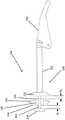
图1是常规压力调节器的横截面图;Figure 1 is a cross-sectional view of a conventional pressure regulator;
图2a到图2c是根据本发明的实施方案的控制组件的横截面图,其中杆组件分别处于第一定向、第二定向和第三定向;Figures 2a-2c are cross-sectional views of a control assembly according to an embodiment of the present invention with the rod assembly in a first orientation, a second orientation and a third orientation, respectively;
图2d是根据本发明的实施方案的控制组件的横截面图,所述控制组件具有带有通道的次级控制构件;Figure 2d is a cross-sectional view of a control assembly having a secondary control member with passages in accordance with an embodiment of the present invention;
图2e是根据本发明的实施方案的控制组件的横截面图,所述控制组件具有带有倾斜表面的次级控制构件;和Figure 2e is a cross-sectional view of a control assembly having a secondary control member with a sloped surface in accordance with an embodiment of the present invention; and
图3a到图3d是根据本发明的实施方案的控制组件的横截面图,其中每个控制组件具有机械止动件。Figures 3a-3d are cross-sectional views of control assemblies, wherein each control assembly has a mechanical stop, according to an embodiment of the present invention.
具体实施方式Detailed ways
呈现以下论述以使本领域技术人员能够制造和使用本发明的实施方案。本领域的技术人员将显而易见对所图示的实施方案的各种修改,且可在不脱离本发明的实施方案的情况下将本文中的一般原理应用于其他实施方案和应用。因此,本发明的实施方案并不旨在限于所示出的实施方案,而是应被赋予与本文所公开的原理和特征相一致的最广范围。将参考附图理解以下详细描述,其中不同附图中的相似元件具有相似的附图标记。不一定按比例绘制的附图描绘了选择的实施方案,并且并不旨在限制本发明的实施方案的范围。技术人员将认识到,本文提供的实例具有许多有用的替代方案,并且落入本发明的实施方案的范围内。The following discussion is presented to enable any person skilled in the art to make and use embodiments of the invention. Various modifications to the illustrated embodiments will be readily apparent to those skilled in the art, and the generic principles herein may be applied to other embodiments and applications without departing from embodiments of the invention. Thus, embodiments of the present invention are not intended to be limited to the embodiments shown, but are to be accorded the widest scope consistent with the principles and features disclosed herein. The following detailed description will be understood with reference to the accompanying drawings, wherein like elements in different drawings have like reference numerals. The drawings, which are not necessarily to scale, depict selected embodiments and are not intended to limit the scope of the embodiments of the invention. Skilled artisans will recognize that the examples provided herein have many useful alternatives that fall within the scope of embodiments of the present invention.
在详细地解释本发明的任何实施方案之前,应理解,本发明在其应用方面不限于以下描述中阐述的或以下附图中图示的构造细节和部件布置。本发明能够具有其他实施方案且能够以各种方式实践或进行。此外,应理解,本文中所使用的措辞和术语是出于描述的目的,而不应视为限制性的。例如,本文中“包括”、“包含”或“具有”及其变型的使用意在涵盖其后列出的项目及其等同物以及附加项目。Before explaining any embodiment of the invention in detail, it is to be understood that the invention is not limited in its application to the details of construction and the arrangements of parts set forth in the following description or illustrated in the accompanying drawings. The invention is capable of other embodiments and of being practiced or carried out in various ways. Also, it is to be understood that the phraseology and terminology used herein is for the purpose of description and should not be regarded as limiting. For example, the use of "including", "including" or "having" and variations thereof herein is intended to encompass the items listed thereafter and equivalents thereof as well as additional items.
如本文所用,除非另外指定或限制,否则如参照物理连接所使用的术语“安装”、“连接”、“支撑”、“固定”和“联接”及其变型被宽泛地使用并且涵盖直接和间接安装、连接、支撑和联接。此外,除非另外指定或限制,否则“连接”、“附接”或“联接”不限于物理或机械连接、附接或联接。As used herein, unless otherwise specified or limited, the terms "mounted," "connected," "supported," "secured," and "coupled" and variations thereof as used with reference to a physical connection are used broadly and encompass both direct and indirect Mounting, connecting, supporting and coupling. Furthermore, "connected," "attached," or "coupled" is not limited to physical or mechanical connections, attachments, or couplings, unless otherwise specified or limited.
如上所述,压力调节器可以用于在各种情况下调节气流的压力。在一些配置中,常规压力调节器的故障模式可以允许气体相对无阻碍地流过压力调节器。因此,可能有必要在其他位置确定内部减压阀或减压阀的尺寸以适应相对较大的流量或压力。这会导致总体成本和系统复杂性的显着增加。As mentioned above, pressure regulators can be used to regulate the pressure of the gas flow under various conditions. In some configurations, the failure mode of conventional pressure regulators may allow relatively unimpeded flow of gas through the pressure regulator. Therefore, it may be necessary to size the internal pressure relief valve or pressure relief valve elsewhere to accommodate relatively large flows or pressures. This results in a significant increase in overall cost and system complexity.
本发明的实施方案可以解决这个问题和其他问题,包括通过提供可以在调节器的可能故障模式操作期间(例如,在杠杆断开事件之后)自动调节气流压力的机械装置。例如,在一些实施方案中,压力调节器的杆组件可以包括在压力调节器的孔口组件的相对侧上的初级控制构件和次级控制构件。在第一操作模式(例如,正常操作)期间,通过杆的移动,初级控制构件可以操作以阻断或允许穿过孔口组件的流动,并且在第二操作模式期间(例如,在杠杆断开事件或其他故障之后),次级控制构件可以操作以阻止或以其他方式限制穿过孔口组件的流动。Embodiments of the present invention may address this and other problems, including by providing a mechanism that can automatically adjust airflow pressure during possible failure mode operation of the regulator (eg, after a lever disconnect event). For example, in some embodiments, the stem assembly of the pressure regulator may include a primary control member and a secondary control member on opposite sides of the orifice assembly of the pressure regulator. During a first mode of operation (eg, normal operation), through movement of the lever, the primary control member may operate to block or allow flow through the orifice assembly, and during a second mode of operation (eg, when the lever is disconnected) event or other failure), the secondary control member may operate to prevent or otherwise restrict flow through the orifice assembly.
作为另一个实例,在一些实施方案中,可以在压力调节器的杆上提供机械止动件。在第一操作模式期间,机械止动件可以允许杆和相关联的控制构件自由移动,以便阻断或允许穿过压力调节器的孔口组件的流动。相反,在第二(例如,杠杆断开)操作模式期间,机械止动件可以接触压力调节器的止动件特征,以便限制控制构件移离孔口组件,从而限制压力调节器的最大流量。As another example, in some embodiments, a mechanical stop may be provided on the stem of the pressure regulator. During the first mode of operation, the mechanical stop may allow the lever and associated control member to move freely in order to block or allow flow through the orifice assembly of the pressure regulator. Conversely, during the second (eg, lever off) mode of operation, the mechanical stop may contact a stop feature of the pressure regulator to limit movement of the control member away from the orifice assembly, thereby limiting maximum flow of the pressure regulator.
图1描绘了常规压力调节器100的一个实例。压力调节器100通常被配置为在内部环境中使用(例如,在住宅建筑中),但是压力调节器100或可以实施本发明的实施方案的其他压力调节器也可以安装在外部环境中(例如,户外)。在这个实例中,压力调节器100包括阀体104、控制组件108、致动器组件112和内部减压阀172。然而,在其他实例中,压力调节器的其他配置是可能的,包括本发明的实施方案可以有利地应用在其上的其他配置。FIG. 1 depicts an example of a
阀体104限定流体入口116、流体出口120和流体流动路径124。当压力调节器100处于打开配置(未示出)时,流体流动路径124在流体入口116与流体出口120之间延伸。流动孔口128沿着流体流动路径124设置在阀体104中,如由设置在流体入口116与流体出口120之间的孔口组件126限定。尽管孔口组件126示出为具有用于控制构件的相对(上游和下游)座的单件式插入件,但其他孔口组件可以与阀体一体式形成,或可以形成为通过一个或多个阀座共同限定可密封流动孔口的多件式组件。The
如下文进一步描述,控制组件108被配置为用于在阀体104中相对于孔口组件126位移,以控制通过孔口128的流体流动。在所图示的实施方案中,控制组件108包括被配置为阀塞132的控制构件、杠杆188和将阀塞132连接到杠杆188的阀杆136,尽管其他配置也是可能的。当压力调节器100处于关闭配置时,如图1所图示,阀塞132定位为抵靠(即,坐落在)孔口组件126,从而阻断工艺流体沿着流动路径124流动(即,防止入口116处的流体流到出口120)。As described further below, the
致动器组件112可操作地连接到阀体104以控制控制组件108相对于孔口组件126的位置。致动器组件112包括外壳140、设置在外壳140内的隔膜144,以及可操作地将隔膜144连接到控制组件108的连杆。致动器外壳140由隔膜壳体146和弹簧壳体148形成,隔膜壳体146和弹簧壳体148例如用连接壳体146、148的相应外法兰的一个或多个螺栓来固定在一起。隔膜144将外壳140分隔成第一腔室150和第二腔室152。第一腔室150至少部分地由隔膜144的一侧和隔膜壳体146限定。第二腔室152至少部分地由隔膜144的另一侧和弹簧壳体148限定。The
排气通风口156形成在弹簧壳体148中并延伸到第二腔室152中。排气通风口156包括从通风入口164延伸到通风出口168的孔口160。通风入口164与第二腔室152流体连通,并且通风出口168与周围环境大气流体连通,使得排气通风口156将第二腔室152流体连接到周围环境大气。相应地,在一些配置中,第二腔室152可以保持在大约等于周围环境大气压力的压力下。An
内部减压阀172形成在隔膜144中并且由不可调节的减压弹簧174调节。内部减压阀172通过在过压的情况下通过隔膜144将流体释放到大气中来为下游系统提供过压保护。任何高于不可调节的减压弹簧174的开始排放点的压力将隔膜144从减压座176移开,从而允许过量压力通过排气通风口156排放。An
为了在正常操作期间控制通过调节器100的流动,杠杆188的第一端可操作地连接到隔膜144的连杆,并且杠杆188的第二端可操作地连接到阀杆136。因此,响应于第一腔室150(和出口120)中的压力变化的隔膜144的移动导致连杆移动杠杆,如下文进一步详述,这移位控制组件108以将工艺流体保持在流体出口120处的预选择压力范围内。To control flow through
致动器组件112还包括控制弹簧196、第一弹簧座200和第二弹簧座204。第一弹簧座200设置在致动器外壳140的第二腔室152内的隔膜144的顶部,并且接纳和支撑控制弹簧196的第一端。同样设置在第二腔室152内的第二弹簧座204接纳控制弹簧196的与第一端相对的第二端。如此布置,控制弹簧196以选择的力在抵抗流体压力的方向(例如,在图1所示定向上的向下方向)上偏压隔膜144,以将工艺流体的压力保持在流体出口120处的预选择范围内。由控制弹簧196施加的力可以通过第二弹簧座204或通过任何其他已知的装置(例如,调节螺钉)来调节。如图1所图示,致动器组件112还可以包括诸如阀塞和释放弹簧之类的部件,它们设置在内部减压阀172中并且用于衰减压力调节器100的响应。The
如上简要所述,通过如图所示配置的压力调节器100,基于隔膜的致动器组件112控制控制组件108的阀塞132相对于孔口组件126的位置,以满足期望的工艺控制参数(例如,期望的设定点压力)。致动器组件112的弹簧196自然地将隔膜144相对于图1的定向向下偏压,所述偏压通过杠杆188转化为控制组件108朝向打开位置(即,阀塞132远离孔口组件126定位)的偏压。然而,与第一腔室150连通的出口120处的压力增加(例如,穿过壁118上的喉部)可以向上推动隔膜144。从而出口120处充分的压力增加可以克服由弹簧196施加的力以移动隔膜144(例如,在图1所示定向上向上)。隔膜的这种移动又可以将杠杆188、阀杆136和阀塞132移向关闭位置(如图1所示)。相反,当出口120处的流体压力充分降低时,例如响应于压力调节器100下游流体需求的增加,弹簧196可以克服第一腔室150中降低的流体压力并移动隔膜144(例如,向下)以将杠杆188、阀杆136和阀塞132移回打开位置。As briefly described above, with the
在使用期间,压力调节器100可能会受到振动引起的磨损或其他不利影响。在一些情况下,这会导致断开故障,其中杠杆188与阀杆136断开,或者从隔膜144到阀杆136的机械连接被破坏。断开故障或诸如隔膜144穿孔的其他部件故障有时会导致全开型故障,其中控制组件108保持不受控制地打开并且压力调节器100不再能够令人满意地调节流动。因此,例如,可以提供如上所述的内部减压阀172或其他下游减压阀用于过压保护。然而,在大流量应用中,适当尺寸的减压阀可能体积大、成本高,或在其他方面不太理想。例如,为了有效地提供过压保护,内部减压阀172(或其他减压阀)的尺寸可以部分地由孔口128的尺寸决定,所述尺寸在大流量应用中可能相对较大。During use, the
同样如上所述,鉴于这些问题和其他问题,提供具有次级控制构件或机械止动件的控制组件可能是有用的,以有助于阻断或以其他方式限制通过压力调节器的流动,包括在操作期间在杠杆断开故障或其他故障事件之后。以这种方式,例如,内部或其他减压阀(例如,阀172)的尺寸可以减小,因为使减压阀与调节器的主孔口(例如,孔口128)的全部容量相匹配的需要可以去除。因此,在一些实施方案中并且如下文进一步详述,次级控制构件可以联接到阀杆以限制来自调节器孔口的上游侧的流体流动,或者在一些操作模式中,机械止动件可以联接到阀杆以限制阀杆的行程。Also as noted above, in light of these and other concerns, it may be useful to provide a control assembly with a secondary control member or mechanical stop to help block or otherwise restrict flow through the pressure regulator, including After a lever disconnect failure or other failure event during operation. In this manner, for example, the size of the internal or other relief valve (eg, valve 172 ) may be reduced because the relief valve is matched to the full capacity of the regulator's main orifice (eg, orifice 128 ). Can be removed as needed. Thus, in some embodiments and as described in further detail below, a secondary control member may be coupled to the valve stem to restrict fluid flow from the upstream side of the regulator orifice, or in some modes of operation, a mechanical stop may be coupled to the valve stem to limit the travel of the valve stem.
图2a到图2e图示了根据本发明的实施方案的控制组件208,控制组件208包括不同的次级控制构件。通常,控制组件208可以用于多种不同的压力调节器,包括与压力调节器100(参见图1)类似地配置的那些,具有通过孔口组件的主动流孔口和被配置为移动杠杆以控制通过主流动孔口的流动的隔膜。例如,压力调节器100可以修改为包括控制组件208的部分或全部,可以最初与控制组件208一起制造,或者可以改装为接纳控制组件208来代替如图1所图示的控制组件108。因此,对于本文所呈现的实例,在孔口128和孔口组件126的背景下讨论控制组件208。然而,在其他实施方案中,根据本发明的控制组件208或其他控制组件可以与其他孔口组件一起使用。Figures 2a-2e illustrate a
在所图示的实施方案中,控制组件208包括杠杆288,杠杆288被配置为附接到致动器组件(例如,图1所示的组件112)和杆组件238。杆组件238具有初级控制构件232和次级控制构件234,两者均固定到阀杆236。初级控制构件232可被配置为阀塞或阀瓣,或可选择性地限制通过孔口(例如,图1的孔口128)的流动的另一机械结构或组件。杠杆288机械地联接到阀杆236的远端,并且初级控制构件232和次级控制构件234机械地(例如,刚性地)联接到阀杆236的近端。在一些实施方案中,初级控制构件232和次级控制构件234可以与阀杆236的部分或全部一起模制成一个整体零件。在一些实施方案中,控制构件232、234可以单独形成,然后稍后固定(例如,销钉或夹住)到阀杆236。In the illustrated embodiment, the
为了适应通过相关调节器孔口的流动,初级控制构件232和次级控制构件234在阀杆236上彼此间隔开。特别地,杆的延伸部分240在初级控制构件232与次级控制构件234之间延伸。在一些实施方案中,延伸部分240可以与阀杆236的主杆分开,并且可以呈现与主杆不同的直径或组成。在一些实施方案中,延伸部分240可以与控制构件232、234中的一个或多个或阀杆236的主杆一体式形成。The
有用地,延伸部分240呈现的长度的尺寸设计成,当控制组件208被安装以供使用时,初级控制构件232被定位在孔口组件126的下游侧220上,次级控制构件234被定位在孔口组件126的上游侧216上,并且阀杆236的延伸部分240延伸穿过由孔口组件126限定的孔口128。在这种布置的情况下,通过孔口组件126的流动可以在任一侧220、216上分别由初级控制构件232或次级控制构件234限制(例如,阻断)。例如,当控制组件208由隔膜致动时,初级控制构件232和次级控制构件234可以通过部分或完全密封孔口组件126的对应下游或上游侧220、216来限制流动。Usefully, the
在不同的实施方案中,控制构件可以呈现不同的形式。例如,在图2a到图2e中,初级控制构件232是在非密封侧具有倒角边缘的实心盘,并且在图2a到图2c中,次级控制构件234是没有倒角边缘的实心盘。然而,在其他实施方案中,其他配置是可能的,包括复合配置(即,多件式或多材料式配置)和具有不同于图2a到图2c所示几何形状的配置(例如,如图1中的阀塞132所图示)。In different embodiments, the control member may take different forms. For example, in Figures 2a-2e, the
作为控制构件的替代配置的一个实例,如图2d中示意性地示出,次级控制构件234A包括允许次级流体流入流体入口116的通道228,包括当次级控制构件234接触孔口组件126的上游侧216时。作为另一个实例,如图2e所示,次级控制构件234B可以包括倾斜轮廓,所述倾斜轮廓面向孔口组件126的上游侧216并且被配置为与之抵靠。因此,随着阀杆236将控制构件234移向孔口组件126,可以更逐渐地限制流动。As an example of an alternative configuration of the control member, as shown schematically in FIG. 2d , the
在其他实施方案中,其他配置也是可能的。例如,次级控制构件的倾斜轮廓可以被配置为与图2e示出的不同,以便在次级控制构件相对于孔口组件移动时提供任意数量的期望流动控制特征。并且,可以以其他方式定制斜面或其他轮廓,以便在次级控制构件连续朝向孔口组件移动时提供任何种类的连续增加(或其他)的流动限制。在一些实施方案中,次级控制构件可以被配置为笼,或以其他方式被配置为包括其他通孔布置,例如可以允许次级流体流动(例如,类似于图2d的配置)。因此,根据特定应用的需要,次级控制构件可以被配置为以多种方式限制穿过调节器孔口的流动,包括在处于完全关闭位置时(例如,当抵靠相关孔口组件就位时)全部或部分地阻断流体流动。In other embodiments, other configurations are also possible. For example, the sloped profile of the secondary control member may be configured differently than shown in Figure 2e to provide any number of desired flow control characteristics as the secondary control member is moved relative to the orifice assembly. Also, the ramps or other profiles may be otherwise tailored to provide any kind of continuously increasing (or other) flow restriction as the secondary control member continues to move towards the orifice assembly. In some embodiments, the secondary control member may be configured as a cage, or otherwise configured to include other arrangements of through holes, such as may allow secondary fluid flow (eg, similar to the configuration of Figure 2d). Thus, depending on the needs of a particular application, the secondary control member may be configured to restrict flow through the regulator orifice in a variety of ways, including when in a fully closed position (eg, when seated against the associated orifice assembly) ) completely or partially block fluid flow.
通常,根据本发明的实施方案,具有多个控制构件的阀杆组件可以用于在调节器的多种不同操作模式中调节流动。例如,控制组件208通常可以在相关压力调节器的至少两种操作模式期间调节通过孔口128的流动。在第一“附接”操作模式中,杆236机械地联接到杠杆288(参见例如图2a和图2b)以在相关隔膜与阀杆236之间传递移动,就像在压力调节器100的正常操作期间的情况一样。在附接操作期间,控制组件208由相关致动器组件在调节器主体104内平移,使得相关隔膜响应于压力变化的移动导致杠杆288移动杆组件238。Generally, according to embodiments of the present invention, a valve stem assembly having multiple control members can be used to regulate flow in a variety of different operating modes of the regulator. For example, the
对于所图示的实施方案,控制组件208被配置为当在附接操作模式中操作时在两个定向之间连续移动,如图2a和图2b所图示。通常,如由杠杆288控制,阀杆236在附接操作期间可以在第一定向与第二定向之间自由移动,尽管一些实施方案可以包括也可能影响阀杆236的移动的其他控制装置。For the illustrated embodiment, the
特别是,图2a示出了处于第一定向的阀杆236,其中初级控制构件232和次级控制构件234处于各自的第一位置。在所图示的实施方案中,初级控制构件232在第一位置完全抵靠孔口组件126就位,并且沿着通过调节器的流动路径(并且穿过孔口128)的流体流动被完全阻断。相反,次级控制构件234在第一位置与孔口组件126的座间隔开,使得在阀杆236开始移动初级控制构件232远离孔口组件126以允许通过孔口128的流动时,次级控制构件234可以提供通过孔口128的最小流动限制。In particular, Figure 2a shows valve stem 236 in a first orientation with
图2b(和图2e)示出了处于第二定向的阀杆236,其中初级控制构件232和次级控制构件234处于相应的第二位置。特别地,控制构件232、234都与孔口组件126的相应侧220、216分开(即,间隔开),使得控制构件232、234中的任一个都不会完全阻断通过孔口128的流动。Figure 2b (and Figure 2e) shows valve stem 236 in a second orientation with
取决于控制构件232、234、延伸部分240和孔口组件126的共同配置,当阀杆236处于第二定向时,控制构件232、234仍可以在一定程度上限制通过孔口128的流动。在一些实施方案中,如下文还讨论的,控制构件232、234可以被配置为当阀杆236处于第二定向时,与孔口组件126的相应侧220、216分开,以允许通过孔口128的最大操作流量。在这点上,例如,在阀杆236处于第二定向的情况下,阀杆236与杠杆288的接合可以防止阀杆236在阀打开方向(例如,图2b中向右)上的进一步移动,因此与孔口组件126和控制构件232、234中的一个或两者合作,限定了压力调节器100的最大操作流量。然而,在其他实施方案中,阀杆236的其他位置可以对应于最大操作流量。Depending on the co-configuration of the
继续,在一些实施方案中,第二“断开”操作模式的特征可以是压力调节器内的部件故障,例如隔膜穿孔、杠杆与阀杆或杠杆与连杆之间的断开故障,或其他可能会阻止隔膜调节通过压力调节器的流动的条件。在以断开操作模式的操作期间,次级控制构件通常可以提供抵抗过量流动的逆止器,流体流过相关调节器的压力倾向于将次级控制构件移向相关的孔口组件,从而减小调节器的当前整体流量。Continuing, in some embodiments, the second "disconnect" mode of operation may be characterized by a component failure within the pressure regulator, such as a diaphragm perforation, a disconnect failure between a lever and a valve stem or a lever and a connecting rod, or other Conditions that may prevent the diaphragm from regulating flow through the pressure regulator. During operation in the disconnected mode of operation, the secondary control member may generally provide a backstop against excess flow, the pressure of fluid flowing through the associated regulator tends to move the secondary control member towards the associated orifice assembly, thereby reducing The current overall flow of the small regulator.
作为一个实例,断开模式的特征可以是杠杆288与阀杆236断开,如图2c(和图2d)所示。在这种情况下,杠杆288可以因此不再阻止阀杆236在阀打开方向上移动。在常规调节器(例如,如图1所示)中,这可能导致穿过孔口128的基本上不受限制的流动。然而,随着移动通过调节器的流体的压力作用在控制构件232、234上,阀杆236可以从第二定向(例如,参见图2b)向第三定向(例如,参见图2c)移动,次级控制构件234对应地朝向孔口组件126的上游侧216移动。因此,在充分的压力下,初级控制构件232和次级控制构件234可以移动到相应第三位置,其中次级控制构件234被特别地移动以在孔口组件126的上游侧216上就位。As an example, the disconnect mode may be characterized by the
如图2c所示,初级控制构件232当移动到第三位置时以及当处于第三位置时与孔口组件126的下游侧220分开的距离大于当在第二位置时的距离。这种配置可以对应于初级控制构件232在孔口组件126的下游侧220处施加减小的流动限制。但是,次级控制构件234朝向孔口组件126的对应移动可以抵消这种影响,并且在次级控制构件234朝向孔口组件126移动时,在孔口组件126的上游侧216处的流动限制持续增加,并且压力调节器的工作流量对应地持续下降。As shown in Figure 2c, the
在一些实施方案中,如图2c所示,次级控制构件的第三位置可以包括次级控制构件抵靠相关的孔口组件就位,尽管其他配置也是可能的。因此,取决于次级控制构件和孔口组件的配置,第三位置可以对应于完全阻断通过孔口组件的流动,使得次级控制构件可以有效地阻止通过调节器的流动。例如,当配置为实心盘或其他不可渗透部件时,如图2c中的次级控制构件234所图示,次级控制构件在抵靠孔口组件就位时可以完全阻断通过调节器的流动。In some embodiments, as shown in Figure 2c, the third position of the secondary control member may include seating of the secondary control member against the associated orifice assembly, although other configurations are possible. Thus, depending on the configuration of the secondary control member and the orifice assembly, the third position may correspond to completely blocking flow through the orifice assembly such that the secondary control member may effectively block flow through the regulator. For example, when configured as a solid disk or other impermeable component, as illustrated by
然而,在其他实施方案中,其他配置是可能的。在一些实施方案中,次级控制构件可以被配置为在断开(或其他第二模式)操作期间限制但不完全阻止通过压力调节器的流动。例如,次级控制构件可以形成为包括面向相关的孔口组件的笼件(未示出),使得即使当次级控制构件在孔口组件上就位时,可以允许通过孔口组件的一些流动。类似地,同样如上所述,次级控制构件可以包括通道(例如,图2d中的通道228),即使当次级控制构件位于孔口组件上时,也可以允许通过孔口组件的次级流体流动。在这类实施方案中,可以选择相关通道(例如,通道228)或笼件特征的尺寸和其他几何形状,以在断开(或其他)模式的延长操作期间限定受限制的最小流量。与本文中的其他讨论一致,有时可以有用地选择这类受限制的最小流量,使得特定的内部(或其他)减压阀能够在断开(或其他)模式期间释放或以其他方式适当地控制最大可能流动。However, in other embodiments, other configurations are possible. In some embodiments, the secondary control member may be configured to restrict, but not completely prevent, flow through the pressure regulator during off (or other second mode) operation. For example, the secondary control member may be formed to include a cage (not shown) facing the associated orifice assembly so that some flow through the orifice assembly may be permitted even when the secondary control member is in place on the orifice assembly . Similarly, as also described above, the secondary control member may include a channel (eg,
同样如上所述,在一些实施方案中,控制构件沿阀杆的间隔(例如,延伸部分的长度)可以被配置为在不同操作模式中提供操作流量限制的期望特征。在一些实施方案中,初级控制构件和次级控制构件可以彼此间隔开,使得次级控制构件在附接操作期间朝向孔口组件的移动不会过度限制整体流动。例如,可以选择在附接操作期间次级控制构件与孔口组件的最小间隔,以将流入相关孔口的流动限制为不超过在附接操作期间初级控制构件与孔口组件的最大间隔。以这种方式,例如,只有在进入断开模式时,当次级构件能够移动更靠近孔口组件时,次级控制构件才可以显着地影响通过调节器的流动。Also as described above, in some embodiments, the spacing of the control member along the valve stem (eg, the length of the extension) may be configured to provide desired characteristics of operational flow restriction in different modes of operation. In some embodiments, the primary control member and the secondary control member may be spaced apart from each other such that movement of the secondary control member toward the orifice assembly during an attachment operation does not unduly restrict overall flow. For example, the minimum separation of the secondary control member and the orifice assembly during the attachment operation may be selected to limit flow into the associated orifice to not exceed the maximum separation of the primary control member and the orifice assembly during the attachment operation. In this way, the secondary control member can significantly affect flow through the regulator only when the secondary member is able to move closer to the orifice assembly, for example, when the disconnected mode is entered.
作为一个实例,如图2b所图示,在附接操作期间阀杆236处于第二定向时,最小距离W1被限定在次级控制构件234与孔口组件126的上游侧216之间,并且最大距离W2被限定在初级控制构件232与孔口组件126的下游侧220之间。特别地,在所图示的实施方案中,延伸部分240的尺寸设计成,当阀杆236与杠杆288的接合约束阀杆236的移动时,距离W1和距离W2彼此基本上相等。以这种方式,例如,考虑到孔口组件126的上游侧216和下游侧220处的孔口128的等效直径,调节器的最大附接模式流量由初级控制构件232和距离W2控制,并且不受次级控制构件234和距离W1限制。As one example, as illustrated in Figure 2b, when the
然而,在其他实施方案中,其他配置是可能的。例如,在一些实施方案中,延伸部分240的尺寸可以设计成,当杠杆288阻止阀杆236在阀打开方向上的移动时,W1小于W2。因此,也取决于孔口128和孔口组件126的配置,W1可以限定在完全打开配置下的最大流量。相反,在一些实施方案中,当杠杆288阻止阀杆236在阀打开方向上的移动时,W1可以大于W2。此外,同样如上所述,控制构件与孔口组件之间的距离的绝对尺寸可能不能完全由流量决定。例如,流量也可能受到孔口上游或下游端的不同直径或其他不同的各种几何形状、控制构件的不同几何形状(例如,如图2e所示的倾斜几何形状)或其他因素的影响,并且控制构件、延伸部分和其他特征的设计可以相应地进行优化,以提供期望的操作流控制。However, in other embodiments, other configurations are possible. For example, in some embodiments,
因此,本发明的一些实施方案可以为调节器提供改进的性能,包括在断开模式中的操作期间。例如,一出现杠杆断开事件,次级控制构件就可以通过穿过调节器的流动而自动移动,以限制(例如,阻断)通过调节器的流动。在一些情况下,这种布置可以保护下游装置免受过压的影响,并且通常会降低内部或下游减压阀所需的流量。Accordingly, some embodiments of the present invention may provide improved performance for the regulator, including during operation in the disconnected mode. For example, upon a lever open event, the secondary control member may be automatically moved by flow through the regulator to restrict (eg, block) flow through the regulator. In some cases, this arrangement can protect downstream equipment from overpressure and often reduces the flow required by the internal or downstream pressure relief valve.
同样如上所述,一些实施方案可以包括其他特征以在调节器的多种操作模式期间提供流动控制,例如杆组件上的机械止动件,被配置为接触调节器的止动件特征以物理地限制杆组件的移动。在这方面,例如,图3a到图3d图示了根据本发明的实施方案的配备有不同配置的控制组件308的压力调节器100。通常,压力调节器100可以被修改以包括控制组件308,可以与控制组件308一起制造,或者可以被改装以接纳控制组件308。此外,在一些实施方案中,类似于控制组件308的控制组件可以用于与调节器100不同配置的调节器中。Also as described above, some embodiments may include other features to provide flow control during the various operating modes of the regulator, such as a mechanical stop on the rod assembly configured to contact the stop feature of the regulator to physically physically Movement of the rod assembly is restricted. In this regard, for example, Figures 3a-3d illustrate
控制组件308通常包括杠杆388和杆组件338。如类似于图1的常规配置的调节器100的配置所讨论,杠杆388机械地联接到阀杆336的远端,并且控制元件332联接到阀杆336的近端。因此,在附接操作模式期间,隔膜144的移动可以移动杠杆388以移动阀杆336,从而控制通过调节器100的流量。
在图3a所图示的实施方案中,杆组件338具有控制构件332、机械止动件334和阀杆336,其中控制构件332和机械止动件334位于壁118的与杠杆388相反的一侧(即,在壁118与孔口组件126的同一侧)。在操作期间,机械止动件334被配置为接合并入到压力调节器100中的止动件特征,如下文进一步描述。In the embodiment illustrated in Figure 3a, the lever assembly 338 has a
类似于控制构件232(参见例如图2a),控制构件332可以配置为阀塞或阀瓣,或者可以通过与孔口组件(例如,孔口组件126)的相互作用来选择性地限制通过调节器孔口(例如,孔口128)的流动的另一个机械结构。在所图示的实施方案中,控制构件332通过连接组件342联接到阀杆336,连接组件342可以包括焊接、销、机械配合特征或任何其他合适的结构以将控制构件332联接到阀杆336。在其他实施方案中,其他配置是可能的,包括具有与对应阀杆一体式形成的控制构件的配置。Similar to control member 232 (see, eg, FIG. 2a ),
在不同的实施方案中,机械止动件可以以不同的方式配置。在一些实施方案中,机械止动件可以被配置为至少部分地围绕阀杆的环。例如,图3a将机械止动件334图示为形成为细长套筒(即,轴向长度大于半径的套筒)并且沿着阀杆336的纵向轴线延伸的环。然而,在其他实施方案中,其他配置是可能的。例如,被配置为环的机械止动件可以形成为从相关阀杆径向向外延伸的盘或大致环形的夹子。In different embodiments, the mechanical stops may be configured in different ways. In some embodiments, the mechanical stop may be configured as a ring at least partially surrounding the valve stem. For example, FIG. 3a illustrates the
在不同的实施方案中,机械止动件可以以不同的方式和在不同的位置固定到阀杆,以便当控制构件处于调节器内的特定位置时接触止动件特征并由此阻止相关联的控制构件的移动。例如,环形机械止动件可以通过阀杆上的凹槽或脊(未示出)、使用固定螺钉、使用卡扣或压配合连接、使用非螺纹销或各种其他方式固定。类似地,机械止动件通常可以固定到相关阀杆上的固定位置,这些位置可以选自沿阀杆长度的任意数量的位置。此外,可以选择机械止动件的一些配置以呈现任何长度中的一个(或多个)。例如,图3a图示了机械止动件334的两种可能的长度A、B。在一些实施方案中,机械止动件可以间接联接到阀杆,例如通过将机械止动件直接联接到控制元件或将控制元件固定到阀杆的连接组件。In different embodiments, the mechanical stop may be secured to the valve stem in different ways and at different locations to contact the stop feature and thereby prevent the associated stop when the control member is in a particular position within the regulator. Controls the movement of widgets. For example, the annular mechanical stop may be secured by grooves or ridges on the valve stem (not shown), using a set screw, using a snap or press fit connection, using a non-threaded pin, or various other means. Similarly, mechanical stops may typically be secured to fixed locations on the associated valve stem, which may be selected from any number of locations along the length of the valve stem. Furthermore, some configurations of mechanical stops can be selected to exhibit one (or more) of any length. For example, FIG. 3a illustrates two possible lengths A, B of the
通常,同样如上所述,当配备机械止动件的阀杆充分移动超出允许的(例如,第一模式)位置范围以达到预定(例如,第二模式)最大位移位置时,机械止动装置可以接触对应止动件特征(或多个特征)以防止相关联的阀杆进一步移动。因此,例如,类似于具有次级控制构件的控制组件(例如,控制组件208),具有机械止动件和止动件特征的控制组件可以在至少两种操作模式(例如,附接操作和断开操作)中提供流动控制,如上所述。Typically, also as described above, when the valve stem equipped with the mechanical stop moves sufficiently beyond the allowable (eg, first mode) range of positions to reach a predetermined (eg, second mode) maximum displacement position, the mechanical stop may Contact the corresponding stop feature (or features) to prevent further movement of the associated valve stem. Thus, for example, similar to a control assembly having a secondary control member (eg, control assembly 208 ), a control assembly with mechanical stops and stop features can operate in at least two modes of operation (eg, attach operation and disconnection). open operation) to provide flow control, as described above.
例如,在装配有控制组件308的调节器100的附接操作期间,阀杆336可以在第一定向与第二定向之间移动,其中控制构件332和机械止动件334分别处于第一对应位置和第二对应位置,用于通过调节器100的流动的一般常规控制。特别地,在附接操作期间,阀杆336可以将控制构件332从控制构件332抵靠孔口组件126就位并且通过孔口128的流体流动被完全阻塞的第一位置移动到类似于图2b的配置的第二位置(未示出),在第二位置中控制构件332与孔口组件126间隔开以允许通过孔口128的流动(例如,最大或无限制的附接模式流动)。For example, during an attachment operation of the
值得注意的是,对于所图示的实施方案,在阀杆336的第一定向和第二定向上(以及在整个附接模式操作中),机械止动件334不与止动件特征相互作用。因此,在附接操作期间,尽管阀杆336与杠杆388的接合防止阀杆336沿阀打开方向移动超过第二定向,但机械止动件334不影响调节器100的操作。Notably, for the illustrated embodiment, in the first and second orientations of the valve stem 336 (and throughout attachment mode operation), the
相反,在断开操作期间,阀杆336可以在远离孔口组件126延伸的方向上移动超过第二定向,从而允许通过调节器100的流动对应地增大。然而,阀杆336充分超过第二定向的移动最终将使机械止动件334进入第三位置(参见图3b),在所述第三位置中,机械止动件334接触止动件特征并由此将阀杆336停止在第三定向处,其中对应的第三位置用于机械止动件334和控制元件332。因此,例如,当杠杆与阀杆336断开或隔膜144以其他方式无法控制阀杆336的移动时,机械止动件334可以接合相关止动件特征以限制孔口128处的最大允许限制,从而防止通过调节器100的无节制流动。Conversely, during a disconnect operation, the
在不同的实施方案中,可以使用不同类型和定向的止动件特征,包括作为常规调节器的整体或预先存在的特征的止动件特征。例如,如图3b所图示,调节器的主要流动路径124与第一腔室150之间的壁118提供了与机械止动件334的套筒接触的止动件特征,从而一旦机械止动件334、阀杆336和控制元件332到达第三位置(参见图3b),就阻止阀杆336在阀打开方向上的移动。在这方面,例如,可以选择机械止动件334沿着阀杆336的长度和安装位置,使得当控制构件332距孔口组件126适当距离时,机械止动件334接触壁118,例如可能对应于断开模式操作的最大允许流动限制。通常,在第三定向中,控制构件332与孔口组件126的下游侧220分开与当阀杆336处于第二定向时相比更大的距离,但与没有采用机械止动件时可能发生的距离相比更小的距离。因此,虽然机械止动件334可能不会阻止通过调节器100的流动,但它仍可以将流动限制在否则可能的最大值以下。In different embodiments, different types and orientations of stop features may be used, including stop features that are integral or pre-existing features of conventional regulators. For example, as illustrated in Figure 3b, the
同样如上所述,机械止动件可以多种不同方式形成和安装。如图3c所示,例如,机械止动件形成为销434,销434沿垂直于阀杆336的纵向轴线的轴线延伸穿过阀杆336。销434可在多个位置机械联接到阀杆336,例如在位置X或位置Y,对套筒(例如,机械止动件334)的位置或长度的改变具有类似的效果,如所讨论的多于。还类似于机械止动件334,销434被配置为与作为止动件特征的壁118一起操作,尽管其他物理结构(例如,阀体104上的其他特征)可以在其他配置中用作止动件特征。因此,在未连接的操作模式中,销434和壁118之间的接触可以防止阀杆336沿阀打开方向(即,图3c中向右)移动超过第三位置(未示出)。Also as described above, the mechanical stops can be formed and installed in a number of different ways. As shown in Figure 3c, for example, the mechanical stop is formed as a
在一些实施方案中,机械止动件可以形成为空腔或其他凹陷特征,其可以被配置为接纳对应止动件特征。例如,如图3d所图示,机械止动件形成为阀杆336中的狭槽534。对应地,止动件特征540形成为延伸到狭槽534中并接触狭槽534的端部(例如,如图所示向左),以防止阀杆336移动超过某个定向(未示出)。止动件特征540可以以多种方式形成,包括作为壁118的整体部分,或作为调节器主体104的其他部分,作为在腔室150内固定到壁118的U形或其他支架的一部分,从壁118、外壳140或外壳148或其他方式延伸的直的、L形的或其他销。如此布置,例如,止动件特征540与狭槽534的端部之间的接触防止阀杆336在压力调节器100内平移,使得阀杆336的移动相对于止动件特征540的位置受限于狭槽534的端部。In some embodiments, the mechanical stops can be formed as cavities or other recessed features that can be configured to receive corresponding stop features. For example, as illustrated in Figure 3d, the mechanical stop is formed as a
同样如上所述,在断开(或其他第二模式)操作期间提供的流动限制程度通常可以通过机械止动件与对应止动件特征之间的相互作用来控制。因此,机械止动件和止动件特征的几何形状和布置有时可以基于机械止动件可以接触止动件特征的操作模式(例如,在断开操作期间)中期望的流动限制程度来选择。例如,关于如图3a到图3d所示,可以选择在断开操作期间流出出口120的期望流量,并且可以计算出控制构件332可以在阀打开方向(例如,如图所示向右)行进的对应最大距离。然后,可以基于计算出的控制构件332的最大行进距离根据需要选择机械止动件334、434、534和对应止动件特征340、440、540的几何形状和布置。Also as described above, the degree of flow restriction provided during the open (or other second mode) operation can generally be controlled by the interaction between the mechanical stop and corresponding stop features. Thus, the geometry and arrangement of the mechanical stops and stop features may sometimes be selected based on the degree of flow restriction desired in modes of operation in which the mechanical stops may contact the stop features (eg, during open operations). For example, with respect to Figures 3a-3d, the desired flow rate out of the
例如,可以选择机械止动件334的套筒的长度和套筒在阀杆336上的位置,使得当阀杆336处于第一定向时(参见图3a),机械止动件334的末端与壁118之间的距离基本上等于控制构件332的期望最大行进距离。因此,机械止动件334和止动件特征340可以将通过流体出口120的流体流动限制为小于在断开操作期间孔口128完全不受限制的情况下的流体流动。类似地,可以根据需要选择销434、狭槽534和机械止动件540的位置和尺寸,以确保可以适当地限制通过调节器100的流动,即使在杠杆388与阀杆336断开时也是如此。For example, the length of the sleeve of the
对于图3a到图3d中所图示的实施方案,机械止动件334、434、534和止动件特征340、440、540被配置为仅在第二模式操作期间(例如,不在调节器100正常操作时)强制实施流动限制。然而,在一些实施方案中,可以选择机械止动件和对应止动件特征的几何形状和布置,使得在附接操作期间控制元件的移动以及对应地流过调节器的流动可以受到机械止动件的限制。For the embodiment illustrated in Figures 3a-3d, the
因此,控制组件308可以保护下游装置免受过压的影响,并且降低内部减压阀172或其他下游减压阀所需的流量。因此,本发明的进一步实施方案还可以为调节器提供改进的性能,包括通过对常规流动控制组件的改进。例如,一旦出现杠杆断开事件,机械止动件控制构件可以自动移动以与止动件特征接触,以限制通过调节器的最大流动。在一些情况下,这种布置可以保护下游装置免受过压的影响,并且通常会降低内部或下游减压阀所需的流量。Thus, the
提供所公开实施方案的先前描述以使得本领域的任何技术人员都能够制造或使用本发明。本领域的技术人员将容易地显而易见对这些实施方案的各种修改,且在不脱离本发明的精神或范围的情况下可将本文中定义的一般原理应用于其他实施方案。因此,本发明不意图局限于本文中所示的实施方案,而是意图就本文中所公开的原理和新颖特征达成最广泛范围的一致。The previous description of the disclosed embodiments is provided to enable any person skilled in the art to make or use the present invention. Various modifications to these embodiments will be readily apparent to those skilled in the art, and the generic principles defined herein may be applied to other embodiments without departing from the spirit or scope of the invention. Thus, the present invention is not intended to be limited to the embodiments shown herein but is to be accorded the widest scope consistent with the principles and novel features disclosed herein.
Claims (20)
Priority Applications (1)
| Application Number | Priority Date | Filing Date | Title |
|---|---|---|---|
| CN202311118093.3ACN117032328A (en) | 2019-11-26 | 2020-11-24 | Pressure regulator |
Applications Claiming Priority (3)
| Application Number | Priority Date | Filing Date | Title |
|---|---|---|---|
| US16/696,096US11022988B1 (en) | 2019-11-26 | 2019-11-26 | Flow limiter for regulators |
| US16/696,096 | 2019-11-26 | ||
| PCT/US2020/061986WO2021108391A1 (en) | 2019-11-26 | 2020-11-24 | Flow limiter for regulators |
Related Child Applications (1)
| Application Number | Title | Priority Date | Filing Date |
|---|---|---|---|
| CN202311118093.3ADivisionCN117032328A (en) | 2019-11-26 | 2020-11-24 | Pressure regulator |
Publications (2)
| Publication Number | Publication Date |
|---|---|
| CN114746828Atrue CN114746828A (en) | 2022-07-12 |
| CN114746828B CN114746828B (en) | 2023-09-08 |
Family
ID=73854948
Family Applications (2)
| Application Number | Title | Priority Date | Filing Date |
|---|---|---|---|
| CN202311118093.3APendingCN117032328A (en) | 2019-11-26 | 2020-11-24 | Pressure regulator |
| CN202080082225.XAActiveCN114746828B (en) | 2019-11-26 | 2020-11-24 | Restrictor for regulator |
Family Applications Before (1)
| Application Number | Title | Priority Date | Filing Date |
|---|---|---|---|
| CN202311118093.3APendingCN117032328A (en) | 2019-11-26 | 2020-11-24 | Pressure regulator |
Country Status (5)
| Country | Link |
|---|---|
| US (2) | US11022988B1 (en) |
| EP (1) | EP4066081B1 (en) |
| CN (2) | CN117032328A (en) |
| CA (2) | CA3162101C (en) |
| WO (1) | WO2021108391A1 (en) |
Families Citing this family (2)
| Publication number | Priority date | Publication date | Assignee | Title |
|---|---|---|---|---|
| US11022988B1 (en)* | 2019-11-26 | 2021-06-01 | Emerson Process Management Regulator Technologies, Inc. | Flow limiter for regulators |
| US11988299B2 (en)* | 2020-12-18 | 2024-05-21 | Bellofram Corporation | Slam shut thermally triggered valve |
Citations (8)
| Publication number | Priority date | Publication date | Assignee | Title |
|---|---|---|---|---|
| GB1178306A (en)* | 1966-01-28 | 1970-01-21 | Clesse Soc D Expl Des Ateliers | Improvements in or relating to Pressure-Reducing and Regulating Valves with Dual Safety Means. |
| US20080257424A1 (en)* | 2007-04-20 | 2008-10-23 | Fisher Controls International Llc | Flow Valve Port for a Gas Regulator |
| CN101675393A (en)* | 2007-02-07 | 2010-03-17 | 环球农业技术及工程有限公司 | Selectively actuated constant flow valve |
| US20130255791A1 (en)* | 2012-03-30 | 2013-10-03 | Emerson Process Managemant Regulator Technologies, Inc. | Fluid regulator having improved flow stability |
| CN105759860A (en)* | 2007-09-14 | 2016-07-13 | 泰思康公司 | Modular In-line Fluid Regulators |
| CN206386539U (en)* | 2015-10-20 | 2017-08-08 | 艾默生过程管理调节技术公司 | Pressure adjustment device and the control assembly for controlling flow of fluid in pressure adjustment device |
| CN110230702A (en)* | 2018-03-06 | 2019-09-13 | 艾默生过程管理调节技术公司 | For reducing the solenoid operated valve of excessive pipeline pressure in fuid distribution system |
| CN209839184U (en)* | 2018-10-29 | 2019-12-24 | 艾默生过程管理调节技术公司 | Fluid regulator and connector assembly therefor |
Family Cites Families (35)
| Publication number | Priority date | Publication date | Assignee | Title |
|---|---|---|---|---|
| US1545990A (en)* | 1923-07-23 | 1925-07-14 | Shirley S Weeks | Fluid-regulating device |
| US2086037A (en)* | 1935-10-28 | 1937-07-06 | Honeywell Regulator Co | Motor operated controller |
| US2581071A (en)* | 1950-06-07 | 1952-01-01 | Paul L Born | Shutoff valve |
| US2619983A (en)* | 1952-01-04 | 1952-12-02 | Fisher Governor Co | Universal diaphragm valve |
| US2698026A (en)* | 1954-05-06 | 1954-12-28 | Fisher Governor Co | Safety shutoff regulator |
| US3042064A (en)* | 1957-04-02 | 1962-07-03 | Rockwell Mfg Co | Gas pressure regulator |
| US3160169A (en)* | 1961-07-17 | 1964-12-08 | Universal Controls Corp | Check valve unit for a diaphragm type pressure regulator |
| US3228417A (en)* | 1963-08-13 | 1966-01-11 | American Meter Co | Pressure regulator with high pressure cut off |
| US3386465A (en)* | 1965-11-22 | 1968-06-04 | American Meter Co | Pressure regulator with internal low pressure shutoff |
| US3424194A (en)* | 1966-07-26 | 1969-01-28 | American Meter Co | Overpressure shutoff device |
| US3542052A (en)* | 1968-08-05 | 1970-11-24 | Fisher Governor Co | Relief monitor for gas service |
| US3488685A (en)* | 1968-09-17 | 1970-01-06 | Textron Inc | Safety valve for regulators |
| US3580271A (en)* | 1968-12-13 | 1971-05-25 | Bryan Donkin Co Ltd | Gas pressure regulators |
| US3599658A (en)* | 1969-07-28 | 1971-08-17 | American Meter Co | Pressure regulator with internal relief valve |
| US3623506A (en)* | 1969-09-22 | 1971-11-30 | Rockwell Mfg Co | Service regulator with high-low pressure cutoff device |
| US3722536A (en)* | 1971-12-17 | 1973-03-27 | Singer Co | Monitor pressure regulator assembly |
| US3754570A (en)* | 1972-06-20 | 1973-08-28 | Textron Inc | Safety control for fluid pressure regulators |
| US3809108A (en)* | 1973-04-16 | 1974-05-07 | Textron Inc | Monitor and automatic shutoff for gas regulators |
| CH574068A5 (en)* | 1973-10-30 | 1976-03-31 | Boillat Pierre | Gas pressure regulator with secondary seal - has coaxially mounted seals for orifice both moved by diaphragm linkage |
| US3892255A (en)* | 1973-12-19 | 1975-07-01 | Singer Co | Inlet orifice device to control thruput flow for pressure regulators |
| US4019531A (en)* | 1974-12-20 | 1977-04-26 | The Singer Company | Inlet orifice device to control thruput flow for pressure regulators |
| US3971410A (en)* | 1975-03-05 | 1976-07-27 | Textron, Inc. | Gas pressure regulator having low pressure shut-off means |
| US4195656A (en)* | 1978-07-07 | 1980-04-01 | The Singer Company | Orifice device with safety shut-off for pressure regulators |
| US4503883A (en)* | 1984-06-15 | 1985-03-12 | The Singer Company | Gas pressure regulator with under and over shut-off |
| US5402820A (en)* | 1993-08-06 | 1995-04-04 | Fisher Controls International, Inc. | Stabilizer for pressure regulator |
| DE29506395U1 (en)* | 1995-04-13 | 1995-06-08 | Rheinauer Maschinen und Armaturenbau Faulhaber & Truttenbach KG, 77866 Rheinau | Gas pressure regulator |
| US6968857B2 (en)* | 2003-03-27 | 2005-11-29 | Emerson Process Control | Pressure reducing fluid regulators |
| RU2470341C2 (en)* | 2007-04-20 | 2012-12-20 | Фишер Контролз Интернешнел Ллс | Built-in device for monitoring excess pressure |
| CN101657772B (en) | 2007-04-20 | 2012-06-06 | 费希尔控制产品国际有限公司 | Secondary Seats for Gas Regulators |
| AU2008242777B2 (en)* | 2007-04-20 | 2011-06-02 | Fisher Controls International Llc | Gas regulator flow boost cartridge |
| US8256446B2 (en)* | 2007-04-23 | 2012-09-04 | Emerson Process Management Regulator Technologies, Inc. | Modular regulator platform |
| JP2011518397A (en)* | 2008-04-21 | 2011-06-23 | エマーソン プロセス マネージメント レギュレーター テクノロジーズ インコーポレイテッド | Pressure load supply pressure regulator with pressure balance trim |
| US20120103440A1 (en)* | 2010-11-01 | 2012-05-03 | Chizek Jared B | Flow directing apparatus for use with fluid regulators |
| CN103671938B (en)* | 2012-09-21 | 2018-02-13 | 艾默生过程管理调节技术公司 | Autoregistration valve port |
| US11022988B1 (en)* | 2019-11-26 | 2021-06-01 | Emerson Process Management Regulator Technologies, Inc. | Flow limiter for regulators |
- 2019
- 2019-11-26USUS16/696,096patent/US11022988B1/enactiveActive
- 2020
- 2020-11-24CNCN202311118093.3Apatent/CN117032328A/enactivePending
- 2020-11-24CACA3162101Apatent/CA3162101C/enactiveActive
- 2020-11-24CACA3187529Apatent/CA3187529A1/enactivePending
- 2020-11-24EPEP20825356.7Apatent/EP4066081B1/enactiveActive
- 2020-11-24CNCN202080082225.XApatent/CN114746828B/enactiveActive
- 2020-11-24WOPCT/US2020/061986patent/WO2021108391A1/ennot_activeCeased
- 2021
- 2021-03-01USUS17/188,967patent/US11353898B2/enactiveActive
Patent Citations (10)
| Publication number | Priority date | Publication date | Assignee | Title |
|---|---|---|---|---|
| GB1178306A (en)* | 1966-01-28 | 1970-01-21 | Clesse Soc D Expl Des Ateliers | Improvements in or relating to Pressure-Reducing and Regulating Valves with Dual Safety Means. |
| CN101675393A (en)* | 2007-02-07 | 2010-03-17 | 环球农业技术及工程有限公司 | Selectively actuated constant flow valve |
| US20080257424A1 (en)* | 2007-04-20 | 2008-10-23 | Fisher Controls International Llc | Flow Valve Port for a Gas Regulator |
| CN101663627A (en)* | 2007-04-20 | 2010-03-03 | 费希尔控制产品国际有限公司 | Improved flow valve port for gas regulator |
| CN105759860A (en)* | 2007-09-14 | 2016-07-13 | 泰思康公司 | Modular In-line Fluid Regulators |
| US20130255791A1 (en)* | 2012-03-30 | 2013-10-03 | Emerson Process Managemant Regulator Technologies, Inc. | Fluid regulator having improved flow stability |
| CN103363168A (en)* | 2012-03-30 | 2013-10-23 | 艾默生过程管理调节技术公司 | Fluid regulator having improved flow stability |
| CN206386539U (en)* | 2015-10-20 | 2017-08-08 | 艾默生过程管理调节技术公司 | Pressure adjustment device and the control assembly for controlling flow of fluid in pressure adjustment device |
| CN110230702A (en)* | 2018-03-06 | 2019-09-13 | 艾默生过程管理调节技术公司 | For reducing the solenoid operated valve of excessive pipeline pressure in fuid distribution system |
| CN209839184U (en)* | 2018-10-29 | 2019-12-24 | 艾默生过程管理调节技术公司 | Fluid regulator and connector assembly therefor |
Also Published As
| Publication number | Publication date |
|---|---|
| CA3187529A1 (en) | 2021-06-03 |
| EP4066081A1 (en) | 2022-10-05 |
| CA3162101A1 (en) | 2021-06-03 |
| CA3162101C (en) | 2023-06-13 |
| EP4066081B1 (en) | 2025-01-15 |
| CN117032328A (en) | 2023-11-10 |
| CN114746828B (en) | 2023-09-08 |
| US20210181771A1 (en) | 2021-06-17 |
| US20210156487A1 (en) | 2021-05-27 |
| WO2021108391A1 (en) | 2021-06-03 |
| US11353898B2 (en) | 2022-06-07 |
| US11022988B1 (en) | 2021-06-01 |
Similar Documents
| Publication | Publication Date | Title |
|---|---|---|
| US8286660B2 (en) | Valve body with dual sense mechanism | |
| CA2681719C (en) | Gas regulator flow boost cartridge | |
| JP5555158B2 (en) | Fluid regulating device and valve port | |
| CN103697202B (en) | Emergency shut-off safety device with guide plug support | |
| JP6267206B2 (en) | Adjustable fixed pressure relief assembly and adjusting device comprising the same | |
| CN107795697B (en) | Stabilizer cartridge for fluid regulator | |
| CN211924897U (en) | Fluid distribution system, assembly for reducing excessive pipeline pressure of fluid distribution system and fluid regulator | |
| CN114746828B (en) | Restrictor for regulator | |
| EP2469370B1 (en) | Service regulator vent | |
| US10823206B2 (en) | Vent limiting device for use with fluid regulators | |
| JP2015530542A (en) | Slam shut (closed with slam-shut-pattern) safety device with guide valve disc |
Legal Events
| Date | Code | Title | Description |
|---|---|---|---|
| PB01 | Publication | ||
| PB01 | Publication | ||
| SE01 | Entry into force of request for substantive examination | ||
| SE01 | Entry into force of request for substantive examination | ||
| GR01 | Patent grant | ||
| GR01 | Patent grant |