CN114744693A - Charging method and electronic equipment - Google Patents
Charging method and electronic equipmentDownload PDFInfo
- Publication number
- CN114744693A CN114744693ACN202210188068.1ACN202210188068ACN114744693ACN 114744693 ACN114744693 ACN 114744693ACN 202210188068 ACN202210188068 ACN 202210188068ACN 114744693 ACN114744693 ACN 114744693A
- Authority
- CN
- China
- Prior art keywords
- charging
- charging device
- mode
- voltage
- charging mode
- Prior art date
- Legal status (The legal status is an assumption and is not a legal conclusion. Google has not performed a legal analysis and makes no representation as to the accuracy of the status listed.)
- Pending
Links
Images


Classifications
- H—ELECTRICITY
- H02—GENERATION; CONVERSION OR DISTRIBUTION OF ELECTRIC POWER
- H02J—CIRCUIT ARRANGEMENTS OR SYSTEMS FOR SUPPLYING OR DISTRIBUTING ELECTRIC POWER; SYSTEMS FOR STORING ELECTRIC ENERGY
- H02J7/00—Circuit arrangements for charging or depolarising batteries or for supplying loads from batteries
- H02J7/007—Regulation of charging or discharging current or voltage
- H02J7/00712—Regulation of charging or discharging current or voltage the cycle being controlled or terminated in response to electric parameters
- H02J7/007182—Regulation of charging or discharging current or voltage the cycle being controlled or terminated in response to electric parameters in response to battery voltage
- H—ELECTRICITY
- H02—GENERATION; CONVERSION OR DISTRIBUTION OF ELECTRIC POWER
- H02J—CIRCUIT ARRANGEMENTS OR SYSTEMS FOR SUPPLYING OR DISTRIBUTING ELECTRIC POWER; SYSTEMS FOR STORING ELECTRIC ENERGY
- H02J9/00—Circuit arrangements for emergency or stand-by power supply, e.g. for emergency lighting
- H02J9/04—Circuit arrangements for emergency or stand-by power supply, e.g. for emergency lighting in which the distribution system is disconnected from the normal source and connected to a standby source
- H02J9/06—Circuit arrangements for emergency or stand-by power supply, e.g. for emergency lighting in which the distribution system is disconnected from the normal source and connected to a standby source with automatic change-over, e.g. UPS systems
- H02J9/061—Circuit arrangements for emergency or stand-by power supply, e.g. for emergency lighting in which the distribution system is disconnected from the normal source and connected to a standby source with automatic change-over, e.g. UPS systems for DC powered loads
- Y—GENERAL TAGGING OF NEW TECHNOLOGICAL DEVELOPMENTS; GENERAL TAGGING OF CROSS-SECTIONAL TECHNOLOGIES SPANNING OVER SEVERAL SECTIONS OF THE IPC; TECHNICAL SUBJECTS COVERED BY FORMER USPC CROSS-REFERENCE ART COLLECTIONS [XRACs] AND DIGESTS
- Y02—TECHNOLOGIES OR APPLICATIONS FOR MITIGATION OR ADAPTATION AGAINST CLIMATE CHANGE
- Y02E—REDUCTION OF GREENHOUSE GAS [GHG] EMISSIONS, RELATED TO ENERGY GENERATION, TRANSMISSION OR DISTRIBUTION
- Y02E60/00—Enabling technologies; Technologies with a potential or indirect contribution to GHG emissions mitigation
- Y02E60/10—Energy storage using batteries
Landscapes
- Engineering & Computer Science (AREA)
- Power Engineering (AREA)
- Business, Economics & Management (AREA)
- Emergency Management (AREA)
- Charge And Discharge Circuits For Batteries Or The Like (AREA)
Abstract
Translated fromChinese
Description
Translated fromChinese技术领域technical field
本申请涉及充电技术,尤其涉及一种充电方法及电子设备。The present application relates to charging technology, and in particular, to a charging method and electronic device.
背景技术Background technique
随着快速充电协议的推出,搭载该快速充电协议的终端产品也越来越多,当支持快速充电协议的终端与支持同样快速充电协议的充电设备连接进行充电时,有时候该充电设备无法工作在快速充电模式下,导致该终端无法以快速充电模式进行充电。With the introduction of the fast charging protocol, there are more and more terminal products equipped with the fast charging protocol. When a terminal supporting the fast charging protocol is connected to a charging device that supports the same fast charging protocol for charging, sometimes the charging device cannot work. In the fast charging mode, the terminal cannot be charged in the fast charging mode.
发明内容SUMMARY OF THE INVENTION
有鉴于此,本申请的技术方案是这样实现的:In view of this, the technical solution of the present application is realized as follows:
根据本申请的一方面,提供一种充电方法,所述方法包括:According to an aspect of the present application, a charging method is provided, the method comprising:
如果充电设备当前处于第一充电模式,向所述充电设备发送触发信号,以使得所述充电设备基于所述触发信号执行电路复位;if the charging device is currently in the first charging mode, sending a trigger signal to the charging device, so that the charging device performs a circuit reset based on the trigger signal;
基于执行所述电路复位,所述充电设备从所述第一充电模式切换为第二充电模式,其中,所述第二充电模式下的充电功率大于所述第一充电模式;The charging device is switched from the first charging mode to a second charging mode based on performing the circuit reset, wherein the charging power in the second charging mode is greater than the first charging mode;
接收所述充电设备在所述第二充电模式下提供的电能。receiving power provided by the charging device in the second charging mode.
上述方案中,基于执行所述电路复位,所述充电设备从所述第一充电模式切换为第二充电模式,包括:In the above solution, based on performing the circuit reset, the charging device is switched from the first charging mode to the second charging mode, including:
向所述充电设备发送第一电压时序信号;sending a first voltage timing signal to the charging device;
接收所述充电设备基于所述第一电压时序信号返回的第一电压参数;receiving a first voltage parameter returned by the charging device based on the first voltage timing signal;
如果所述第一电压参数处于第一预设电压参数范围之内,确定所述充电设备当前处于第二充电模式。If the first voltage parameter is within the first preset voltage parameter range, it is determined that the charging device is currently in the second charging mode.
上述方案中,在所述向所述充电设备发送第一电压时序信号之前,所述方法还包括:In the above solution, before the sending the first voltage timing signal to the charging device, the method further includes:
向所述充电设备发送第二电压时序信号;sending a second voltage timing signal to the charging device;
接收所述充电设备基于所述第二电压时序信号返回的第二电压参数;receiving a second voltage parameter returned by the charging device based on the second voltage timing signal;
如果所述第二电压参数处于第二预设电压参数范围之内,向所述充电设备发送所述第一电压时序信号。If the second voltage parameter is within a second preset voltage parameter range, the first voltage timing signal is sent to the charging device.
上述方案中,向所述充电设备发送第二电压时序信号之前,所述方法还包括;In the above solution, before sending the second voltage timing signal to the charging device, the method further includes;
向所述充电设备发送第三电压时序信号;sending a third voltage timing signal to the charging device;
接收所述充电设备基于所述第三电压时序信号返回的第三电压参数;receiving a third voltage parameter returned by the charging device based on the third voltage timing signal;
如果所述第三电压参数处于第三预设电压参数范围之内,向所述充电设备发送所述第二电压时序信号。If the third voltage parameter is within a third preset voltage parameter range, the second voltage timing signal is sent to the charging device.
上述方案中,向所述充电设备发送第三电压时序信号之前,所述方法还包括;In the above solution, before sending the third voltage timing signal to the charging device, the method further includes;
向所述充电设备发送第四电压时序信号;sending a fourth voltage timing signal to the charging device;
接收所述充电设备基于所述第四电压时序信号返回的第四电压参数;receiving a fourth voltage parameter returned by the charging device based on the fourth voltage timing signal;
如果所述第四电压参数处于第四预设电压参数范围之内,向所述充电设备发送所述第三电压时序信号。If the fourth voltage parameter is within a fourth preset voltage parameter range, the third voltage timing signal is sent to the charging device.
上述方案中,所述方法还包括:In the above scheme, the method also includes:
如果所述第二电压参数处于所述第二预设电压参数范围之外,确定所述充电设备当前处于第三充电模式;If the second voltage parameter is outside the second preset voltage parameter range, determining that the charging device is currently in a third charging mode;
接收所述充电设备在所述第三充电模式下提供的电能;receiving power provided by the charging device in the third charging mode;
或者,如果所述第三电压参数处于所述第三预设电压参数范围之外,确定所述充电设备当前处于第四充电模式;Or, if the third voltage parameter is outside the third preset voltage parameter range, determine that the charging device is currently in a fourth charging mode;
接收所述充电设备在所述第四充电模式下提供的电能;receiving power provided by the charging device in the fourth charging mode;
或者,如果所述第四电压参数处于所述第四预设电压参数范围之外,确定所述充电设备当前处于第五充电模式;Or, if the fourth voltage parameter is outside the fourth preset voltage parameter range, determine that the charging device is currently in a fifth charging mode;
执行所述充电设备在所述第五充电模式下提供的能力。Capabilities provided by the charging device in the fifth charging mode are performed.
上述方案中,在向所述充电设备发送触发信号之前,所述方法还包括:In the above solution, before sending a trigger signal to the charging device, the method further includes:
对所述充电设备的当前充电模式进行标记;marking the current charging mode of the charging device;
根据所述标记,在所述充电设备执行电路复位之后,如果所述标记满足参数条件时,接收所述充电设备在所述第一充电模式下提供的电能。According to the flag, after the charging device performs a circuit reset, if the flag satisfies the parameter condition, the power provided by the charging device in the first charging mode is received.
上述方案中,还包括:The above scheme also includes:
在确定所述充电设备当前处于第二充电模式的情况下,清除对所述充电设备的当前充电模式的标记。If it is determined that the charging device is currently in the second charging mode, the flag of the current charging mode of the charging device is cleared.
上述方案中,所述确定充电设备当前处于第一充电模式,包括:In the above solution, the determining that the charging device is currently in the first charging mode includes:
如果所述第一电压参数处于所述第一预设电压参数范围之外,确定所述充电设备当前处于所述第一充电模式。If the first voltage parameter is outside the first preset voltage parameter range, it is determined that the charging device is currently in the first charging mode.
根据本申请的另一方面,提供一种充电设备,所述充电设备包括:According to another aspect of the present application, there is provided a charging device, the charging device comprising:
发送单元,用于如果充电设备当前处于第一充电模式,向所述充电设备发送触发信号,以使得所述充电设备基于所述触发信号对所述充电设备执行电路复位;a sending unit, configured to send a trigger signal to the charging device if the charging device is currently in the first charging mode, so that the charging device performs a circuit reset on the charging device based on the trigger signal;
切换单元,用于基于执行所述电路复位,使得所述充电设备从所述第一充电模式切换为第二充电模式,其中,所述第二充电模式下的充电功率大于所述第一充电模式;a switching unit configured to switch the charging device from the first charging mode to a second charging mode based on performing the circuit reset, wherein the charging power in the second charging mode is greater than that in the first charging mode ;
接收单元,用于接收所述充电设备在所述第二充电模式下提供的电能。A receiving unit, configured to receive the electric energy provided by the charging device in the second charging mode.
本申请提供的一种充电方法及装置,通过在确定充电设备当前处于第一充电模式的情况下,向所述充电设备发送触发信号,以使得所述充电设备基于所述触发信号执行电路复位;基于执行所述电路复位,所述充电设备从所述第一充电模式切换为第二充电模式;其中,所述第二充电模式下的充电功率大于所述第一充电模式;接收所述充电设备在所述第二充电模式下提供的电能。如此,能够自动判别充电设备是否充电异常,并且能够在充电设备充电异常的情况下,使得该充电设备执行电路复位,以切换到快速充电模式对目标终端进行继续充电。In a charging method and device provided by the present application, when it is determined that a charging device is currently in a first charging mode, a trigger signal is sent to the charging device, so that the charging device performs a circuit reset based on the trigger signal; Based on performing the circuit reset, the charging device is switched from the first charging mode to a second charging mode; wherein the charging power in the second charging mode is greater than the first charging mode; receiving the charging device the electrical energy provided in the second charging mode. In this way, it can be automatically determined whether the charging device is abnormally charged, and when the charging device is abnormally charged, the charging device can be reset to execute a circuit to switch to the fast charging mode to continue charging the target terminal.
附图说明Description of drawings
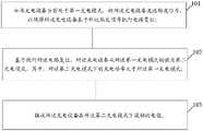
图1为本申请中充电方法的流程示意图一;FIG. 1 is a schematic flowchart 1 of the charging method in the application;
图2为BC1.2充电协议的识别过程示意图;Figure 2 is a schematic diagram of the identification process of the BC1.2 charging protocol;
图3为QC2.0充电协议的识别过程示意图;Figure 3 is a schematic diagram of the identification process of the QC2.0 charging protocol;
图4为本申请中充电方法的流程示意图二;FIG. 4 is a second schematic flowchart of the charging method in the application;
图5为本申请中电子设备结构组成示意图一;FIG. 5 is a schematic diagram 1 of the electronic device structure in the application;
图6为本申请中电子设备的结构组成示意图二。FIG. 6 is a second schematic diagram of the structure and composition of the electronic device in the application.
具体实施方式Detailed ways
以下结合说明书附图及具体实施例对本申请的技术方案做进一步的详细阐述。The technical solutions of the present application will be further elaborated below with reference to the accompanying drawings and specific embodiments of the description.
如图1所示,本实施例提供一种充电方法,包括:As shown in FIG. 1 , this embodiment provides a charging method, including:
步骤101,如果充电设备当前处于第一充电模式,向所述充电设备发送触发信号,以使得所述充电设备基于所述触发信号执行电路复位;
步骤102,基于执行所述电路复位,所述充电设备从所述第一充电模式切换为第二充电模式,其中,所述第二充电模式下的充电功率大于所述第一充电模式;
步骤103,接收所述充电设备在所述第二充电模式下提供的电能。Step 103: Receive electric energy provided by the charging device in the second charging mode.
本申请中,该充电方法可以应用于支持快速充电协议的各种电子设备,比如,该电子设备可以是手机、平板电脑、手机、耳机、个人媒体播放器等等。当该电子设备与支持同样快速充电协议的充电设备连接进行充电的情况下,该电子设备通过监测D+信号线和D-信号线上的电压信号变化,可以判断出该充电设备当前的充电模式是否是快速充电模式,如果确定当前充电设备的充电模式非快速充电模式,则确定当前充电设备的充电状态异常,触发该充电设备执行重启流程。In this application, the charging method can be applied to various electronic devices supporting the fast charging protocol, for example, the electronic device can be a mobile phone, a tablet computer, a mobile phone, an earphone, a personal media player, and so on. When the electronic device is connected to a charging device that supports the same fast charging protocol for charging, the electronic device can determine whether the current charging mode of the charging device is by monitoring the voltage signal changes on the D+ signal line and the D- signal line. It is a fast charging mode. If it is determined that the charging mode of the current charging device is not a fast charging mode, it is determined that the charging state of the current charging device is abnormal, and the charging device is triggered to perform a restart process.
一种实现方式中,如果该电子设备支持高通公司提供的快速充电(QC,QuickCharge)3.0+充电协议,当该电子设备与同样支持QC3.0+充电协议的充电设备连接的情况下,该电子设备可以向该充电设备发送第一电压时序信号,并接收该充电设备基于该第一电压时序信号返回的第一电压参数,如果该第一电压参数处于第一预设电压参数范围之外,则确定该充电设备当前处于第一充电模式(比如QC3.0充电协议的充电模式),此时,该电子设备可以向该充电设备发送触发信号,以使得该充电设备基于该触发信号执行电路复位,并基于该充电设备执行该电路复位,如果该第一电压参数处于第一预设电压参数范围之内,则确定该充电设备当前处于第二充电模式(QC3.0+充电协议的充电模式)。从而实现该充电设备从该第一充电模式切换为第二充电模式的目的。In one implementation, if the electronic device supports the Quick Charge (QC, QuickCharge) 3.0+ charging protocol provided by Qualcomm, when the electronic device is connected to a charging device that also supports the QC3.0+ charging protocol, the electronic The device can send a first voltage timing signal to the charging device, and receive a first voltage parameter returned by the charging device based on the first voltage timing signal. If the first voltage parameter is outside the first preset voltage parameter range, then It is determined that the charging device is currently in the first charging mode (such as the charging mode of the QC3.0 charging protocol), and at this time, the electronic device can send a trigger signal to the charging device, so that the charging device performs a circuit reset based on the trigger signal, The circuit reset is performed based on the charging device, and if the first voltage parameter is within the range of the first preset voltage parameter, it is determined that the charging device is currently in the second charging mode (the charging mode of the QC3.0+ charging protocol). Thus, the purpose of switching the charging device from the first charging mode to the second charging mode is achieved.
这里,第一电压时序信号可以是指该电子设备在识别该充电设备是否是QC3.0+充电协议时的电压时序信号。比如,该电子设备在该充电设备处于QC3.0充电协议下的输出电压是5V,如果第一电压参数表征该电子设备的当前输出电压是6V,则确定该充电设备当前处于QC3.0+模式,如果该电子设备的当前输出电压小于或等于5V,则确定该电子设备当前处于除QC3.0+以外的充电模式(比如QC3.0模式、QC2.0模式或BC1.2模式)。Here, the first voltage timing signal may refer to a voltage timing signal when the electronic device recognizes whether the charging device is in the QC3.0+ charging protocol. For example, the output voltage of the electronic device when the charging device is under the QC3.0 charging protocol is 5V, and if the first voltage parameter indicates that the current output voltage of the electronic device is 6V, it is determined that the charging device is currently in the QC3.0+ mode , if the current output voltage of the electronic device is less than or equal to 5V, it is determined that the electronic device is currently in a charging mode other than QC3.0+ (such as QC3.0 mode, QC2.0 mode or BC1.2 mode).
本申请中,第二充电模式下的充电功率大于第一充电模式。比如,第一充电模式是QC3.0协议模式,第二充电模式是QC3.0+协议模式。其中,QC3.0QC3.0是以每200mV为增量,在3.6V至20V的电压范围内,提供不同电压的弹性选择。QC3.0+协议是在QC3.0基础上升级而来,因此,不需要提高设备成本。In the present application, the charging power in the second charging mode is greater than that in the first charging mode. For example, the first charging mode is the QC3.0 protocol mode, and the second charging mode is the QC3.0+ protocol mode. Among them, QC3.0QC3.0 provides flexible selection of different voltages in the voltage range of 3.6V to 20V in increments of 200mV. The QC3.0+ protocol is upgraded on the basis of QC3.0, so there is no need to increase the equipment cost.
这里,QC3.0充电协议的输出功率可以是15W、18W和20W,QC3.0+充电协议的输出功率通常是大于或等于30W。Here, the output power of the QC3.0 charging protocol can be 15W, 18W and 20W, and the output power of the QC3.0+ charging protocol is usually greater than or equal to 30W.
另外,由于QC3.0+充电协议向前兼容所有的QC充电协议,比如,该QC3.0+向前兼容QC3.0充电协议、QC2.0充电协议、BC1.2充电协议。而充电设备为了兼容所有支持这些充电协议的电子设备,该充电设备在执行电路复位的过程中,可以依次检测这些充电协议对应的电压参数是否满足条件,如果满足条件则会执行下一个充电协议的检测,如果不满足条件则以当前的充电协议向电子设备提供电能。In addition, since the QC3.0+ charging protocol is forward compatible with all QC charging protocols, for example, the QC3.0+ is forward compatible with the QC3.0 charging protocol, the QC2.0 charging protocol, and the BC1.2 charging protocol. In order to be compatible with all electronic devices that support these charging protocols, the charging device can sequentially detect whether the voltage parameters corresponding to these charging protocols meet the conditions during the circuit reset process, and execute the next charging protocol if the conditions are met. Detect, and if the condition is not met, supply power to the electronic device with the current charging protocol.
基于此,该电子设备在向该充电设备发送第一电压时序信号之前,还可以向该充电设备发送第二电压时序信号(比如QC3.0充电协议信号),以检测当前充电设备是否支持QC3.0充电协议。如果接收到该充电设备基于该第二电压时序信号返回的第二电压参数,则判断该第二电压参数是否处于第二预设电压参数范围,如果判断结果表征该第二电压参数处于第二预设电压参数范围之内,则说明该充电设备支持QC3.0充电协议,接着才向该充电设备发送该第一电压时序信号(比如QC3.0+充电协议信号)。Based on this, before sending the first voltage timing signal to the charging device, the electronic device can also send a second voltage timing signal (such as a QC3.0 charging protocol signal) to the charging device to detect whether the current charging device supports QC3.0. 0 charging protocol. If the second voltage parameter returned by the charging device based on the second voltage timing signal is received, it is judged whether the second voltage parameter is within the second preset voltage parameter range, and if the judgment result indicates that the second voltage parameter is within the second preset voltage parameter range If the voltage parameter is within the range, it means that the charging device supports the QC3.0 charging protocol, and then the first voltage timing signal (eg, QC3.0+charging protocol signal) is sent to the charging device.
本申请中,该电子设备在向该充电设备发送第二电压时序信号之前,还可以向充电设备发送第三电压时序信号(比如QC2.0充电协议信号),以检测该充电设备是否支持QC2.0充电协议,并接收该充电设备基于该第三电压时序信号返回的第三电压参数,然后判断该第三电压参数是否处于第三预设电压参数范围之内,如果判断结果表征该第三电压参数处于第三预设电压参数范围之内,则说明该充电设备支持QC2.0充电协议,接着才向该充电设备发送该第二电压时序信号。In this application, before sending the second voltage sequence signal to the charging device, the electronic device may also send a third voltage sequence signal (such as a QC2.0 charging protocol signal) to the charging device to detect whether the charging device supports QC2.0. 0 charging protocol, and receive the third voltage parameter returned by the charging device based on the third voltage timing signal, and then judge whether the third voltage parameter is within the range of the third preset voltage parameter, and if the judgment result represents the third voltage If the parameter is within the range of the third preset voltage parameter, it means that the charging device supports the QC2.0 charging protocol, and then the second voltage timing signal is sent to the charging device.
这里,QC2.0充电协议通常支持5V、9V和12V三种固定电压,在判断手机端和充电器端都支持QC2.0充电协议后,会直接将输入电压从5V跳到9V或12V并一路冲到总电量,从而导致手机功耗非常严重。而QC3.0则支持3.6V~12V的波动电压,允许输入电压从3.6V起步,以0.2V为单位,结合实时的电池温度、转换效率、电量等因素进行微调,并在允许的输入电压范围(9V或12V)内逐步提升或降低。从而降低手机功耗。Here, the QC2.0 charging protocol usually supports three fixed voltages of 5V, 9V and 12V. After judging that both the mobile phone and the charger support the QC2.0 charging protocol, the input voltage will be directly jumped from 5V to 9V or 12V and all the way Rush to the total power, resulting in very serious power consumption of the mobile phone. The QC3.0 supports the fluctuating voltage of 3.6V ~ 12V, allowing the input voltage to start from 3.6V, with 0.2V as the unit, combined with real-time battery temperature, conversion efficiency, power and other factors to fine-tune, and within the allowable input voltage range (9V or 12V) gradually increase or decrease. Thereby reducing the power consumption of the mobile phone.
本申请中,电子设备在向充电设备发送第三电压时序信号之前,还可以向充电设备发送第四电压时序信号(比如电池充电(BC,Battery Charging)1.2信号),以检测该充电设备是否支持BC1.2充电协议;如果该电子设备接收到该充电设备基于该第四电压时序信号返回的第四电压参数,则判断该第四电压参数是否处于第四预设电压参数范围之内;如果判断结果表征该第四电压参数处于第四预设电压参数范围之内,则确定该充电设备支持BC1.2充电协议;接着该电子设备再向该充电设备发送该第三电压时序信号。In this application, before sending the third voltage sequence signal to the charging device, the electronic device may also send a fourth voltage sequence signal (such as a battery charging (BC, Battery Charging) 1.2 signal) to the charging device to detect whether the charging device supports BC1.2 charging protocol; if the electronic device receives the fourth voltage parameter returned by the charging device based on the fourth voltage timing signal, it is determined whether the fourth voltage parameter is within the range of the fourth preset voltage parameter; if it is determined If the result indicates that the fourth voltage parameter is within the range of the fourth preset voltage parameter, it is determined that the charging device supports the BC1.2 charging protocol; then the electronic device sends the third voltage timing signal to the charging device.
这里,BC1.2充电协议用于规范电池充电的需求,通常输出功率是7.5W,BC1.2充电协议主要包括以下几个USB端口类型:标准下行端口(SDP,Standard Downlink Port)、专用充电端口(DCP,Dedicated Charging Port)和下行充电端口(CDP,Downlink ChargingPort)。其中,SDP只支持数据协议,不支持充电协议(比如普通的USB数据传输接口);DCP只支持充电协议,不支持数据协议(比如墙上充电器和车载充电器),CDP即支持数据协议也支持充电协议(比如电脑接口)。而QC2.0、QC3.0和QC3.0+均是在该充电设备是DCP类型的充电端口的情况下才会继续执行检测。Here, the BC1.2 charging protocol is used to standardize the battery charging requirements, and the output power is usually 7.5W. The BC1.2 charging protocol mainly includes the following types of USB ports: Standard Downlink Port (SDP, Standard Downlink Port), dedicated charging port (DCP, Dedicated Charging Port) and Downlink Charging Port (CDP, Downlink ChargingPort). Among them, SDP only supports data protocol, not charging protocol (such as ordinary USB data transmission interface); DCP only supports charging protocol, not data protocol (such as wall charger and car charger), CDP supports data protocol and also Support charging protocol (such as computer interface). QC2.0, QC3.0 and QC3.0+ will continue to perform detection only when the charging device is a DCP type charging port.
本申请中,如果该第二电压参数处于该第二预设电压参数范围之外,该电子设备则确定该充电设备当前处于第三充电模式(比如QC2.0模式),并接收该充电设备在该第三充电模式下提供的电能。如果该第二电压参数处于该第二预设电压参数范围之内,但如果该第三电压参数处于该第三预设电压参数范围之外,该电子设备则确定该充电设备当前处于第四充电模式(比如DCP模式);并接收该充电设备在该第四充电模式下提供的电能。如果该第三电压参数处于该第三预设电压参数范围之内,但如果该第四电压参数处于该第四预设电压参数范围之外,该电子设备则确定该充电设备当前处于第五充电模式(比如CDP模式或SDP模式),并接收该充电设备在该第五充电模式下提供的能力。In this application, if the second voltage parameter is outside the range of the second preset voltage parameter, the electronic device determines that the charging device is currently in a third charging mode (such as QC2. The electrical energy provided in the third charging mode. If the second voltage parameter is within the second preset voltage parameter range, but if the third voltage parameter is outside the third preset voltage parameter range, the electronic device determines that the charging device is currently in fourth charging mode (such as DCP mode); and receive the power provided by the charging device in the fourth charging mode. If the third voltage parameter is within the third preset voltage parameter range, but if the fourth voltage parameter is outside the fourth preset voltage parameter range, the electronic device determines that the charging device is currently in fifth charging mode (such as CDP mode or SDP mode), and receive the capabilities provided by the charging device in the fifth charging mode.
下面,介绍一下各充电模式的识别过程:The following describes the identification process of each charging mode:
图2为BC1.2充电协议的识别过程示意图,如图2所示:Figure 2 is a schematic diagram of the identification process of the BC1.2 charging protocol, as shown in Figure 2:
首先以手机为例在D+信号线上施加0.6V电压,如果手机检测到D-信号线上的电压为0V,则说明D-信号线和D+信号线没有接通,所以D+信号线上的电压无法传输到D-信号线上,此时,确定当前手机连接的USB2.0接口是一个SDP类型的端口,比如手机当前连接的是一个只能传输数据的USB接口。如果手机检测到D-信号线上的电压为0.6V,则会认为自己连接到了一个CDP(大功率充电+通信端口,例如电脑)或者DCP(专用充电端口,例如墙充),因为此时D+信号线和D-信号线是联通的。则手机继续在D-上施加0.6V电压,如果手机检测到D+上的电压为0.6V,则确定手机当前连接的USB接口是一个DCP类型的端口,即手机连接的USB接口是一个专用充电器,接着继续把D+上拉到3V或0.6V。如果手机检测到D+上的电压为0V,则确定手机当前连接的USB接口是一个带有大电流且具有充电能力的CDP类型的端口,比如手机连接的USB接口是一个电脑,接着释放手机上D-和D+上的电压。First, take the mobile phone as an example to apply 0.6V voltage on the D+ signal line. If the mobile phone detects that the voltage on the D- signal line is 0V, it means that the D- signal line and the D+ signal line are not connected, so the voltage on the D+ signal line It cannot be transmitted to the D-signal line. At this time, make sure that the USB2.0 interface currently connected to the mobile phone is an SDP type port. For example, the mobile phone is currently connected to a USB interface that can only transmit data. If the mobile phone detects that the voltage on the D- signal line is 0.6V, it will think that it is connected to a CDP (high-power charging + communication port, such as a computer) or DCP (dedicated charging port, such as a wall charger), because at this time D+ The signal line and the D-signal line are connected. Then the mobile phone continues to apply 0.6V voltage on D-. If the mobile phone detects that the voltage on D+ is 0.6V, it is determined that the USB interface currently connected to the mobile phone is a DCP type port, that is, the USB interface connected to the mobile phone is a dedicated charger. , and then continue to pull up D+ to 3V or 0.6V. If the mobile phone detects that the voltage on D+ is 0V, it is determined that the USB interface currently connected to the mobile phone is a CDP type port with high current and capable of charging. For example, the USB interface connected to the mobile phone is a computer, and then release the D on the mobile phone. - and the voltage on D+.
图3为QC2.0充电协议的识别过程示意图,如图3所示:Figure 3 is a schematic diagram of the identification process of the QC2.0 charging protocol, as shown in Figure 3:
这里,由于QC2.0是以BC1.2充电协议为基础且向前兼容BC1.2充电协议,因此,手机在确定当前连接的USB接口是一个DCP类型的端口的情况下,将D+信号线上拉到3V或6V,然后,控制DCP端口在1.25S后断开D-信号线和D+信号线,接着检测D-信号线上的电压是否下降,如果检测到D-信号线上的电压下降,则确定当前连接的USB接口是QC类型的充电器。Here, since QC2.0 is based on the BC1.2 charging protocol and is forward compatible with the BC1.2 charging protocol, therefore, when the mobile phone determines that the currently connected USB interface is a DCP type port, connect the D+ signal line to the Pull to 3V or 6V, then, control the DCP port to disconnect the D- signal line and the D+ signal line after 1.25S, and then detect whether the voltage on the D- signal line drops, if the voltage on the D- signal line is detected. Then it is determined that the currently connected USB interface is a QC type charger.
本申请中,由于QC3.0充电协议兼容QC2.0充电协议,所以在QC2.0充电协议的流程基础上,手机端接着控制D+信号线和D-信号线让QC充电器的充电头以200mv的步调先升压再降压到默认输出电压(比如5V)。在这个过程中,如果充电头能以200mv的步调完成升压和降压,则确定当前的充电器是QC3.0类型,否则是QC2.0类型。In this application, since the QC3.0 charging protocol is compatible with the QC2.0 charging protocol, based on the process of the QC2.0 charging protocol, the mobile phone then controls the D+ signal line and the D- signal line to let the charging head of the QC charger run at 200mv The pace of the first step up and then step down to the default output voltage (such as 5V). In this process, if the charging head can complete the step-up and step-down of 200mv, it is determined that the current charger is QC3.0 type, otherwise it is QC2.0 type.
比如可以是:先升压3.2V,持续0.1秒后再降压3.2v,如果此时能输出默认电压5v,则是QC3.0类型的充电器。For example, it can be: first boost 3.2V, last for 0.1 seconds and then step down 3.2v, if the default voltage 5v can be output at this time, it is a QC3.0 type of charger.
本申请中,由于QC3.0+充电协议是基于QC3.0充电协议的改进,所以在QC3.0充电协议的流程基础上,如果该充电头是QC3.0+类型的,该充电头会输出更高的电压给手机端,否则不是QC3.0+类型的充电头,而是QC3.0类型的充电头。In this application, since the QC3.0+ charging protocol is based on the improvement of the QC3.0 charging protocol, based on the process of the QC3.0 charging protocol, if the charging head is of the QC3.0+ type, the charging head will output The higher voltage is given to the mobile phone, otherwise it is not a QC3.0+ type charging head, but a QC3.0 type charging head.
比如,在QC3.0充电协议的流程基础上,手机端继续检测充电头的输出电压,如果检测到充电头输出的是6V电压(如QC3.0的充电协议下输出的是默认电压5v),则是QC3.0+类型的充电头。For example, based on the process of the QC3.0 charging protocol, the mobile terminal continues to detect the output voltage of the charging head. If it detects that the output voltage of the charging head is 6V (such as the default voltage 5v output under the charging protocol of QC3.0), It is a QC3.0+ type of charging head.
本申请中,该电子设备在确定该充电设备当前处于第一充电模式的情况下,还可以对该充电设备的当前充电模式进行标记,并在该充电设备执行电路复位之后,如果该标记满足参数条件,则接收该充电设备在该第一充电模式下提供的电能。In the present application, when it is determined that the charging device is currently in the first charging mode, the electronic device may also mark the current charging mode of the charging device, and after the charging device performs a circuit reset, if the mark satisfies the parameter condition, the electric energy provided by the charging device in the first charging mode is received.
这里,标记满足参数条件,至少包括以下方法之一:Here, the marker satisfies the parameter conditions, including at least one of the following methods:
如果该充电设备标记为第一模式的标记次数大于或等于次数阈值,则确定该标记满足条件;If the number of marking times of the charging device marked as the first mode is greater than or equal to the number of times threshold, it is determined that the marking satisfies the condition;
如果该充电设备标记为第一模式的标记时长大于或等于时长阈值,则确定该标记满足条件。If the marking duration of the charging device marked as the first mode is greater than or equal to the duration threshold, it is determined that the marking satisfies the condition.
比如,在该充电设备执行电路复位之后,该电子设备获取该充电设备的标记次数“2”,并将该标记次数与次数阈值“2”进行比较,根据比较结果确定标记次数“2”等于次数阈值“2”,则确定该标记满足条件,接收该充电设备在第一充电模式下提供的电能。For example, after the charging device performs a circuit reset, the electronic device acquires the marking times "2" of the charging device, compares the marking times with the times threshold "2", and determines that the marking times "2" is equal to the number of times according to the comparison result If the threshold value is "2", it is determined that the flag satisfies the condition, and the electric energy provided by the charging device in the first charging mode is received.
再比如,在该充电设备执行电路复位之后,该电子设备获取该充电设备的标记时长“30秒”,并将该标记时长与时长阈值“20秒”进行比较,根据比较结果确定标记时长“30秒大于时长阈值“20秒”,则确定该标记满足条件,接收该充电设备在第一充电模式下提供的电能。For another example, after the charging device performs circuit reset, the electronic device obtains the marking duration "30 seconds" of the charging device, compares the marking duration with the duration threshold "20 seconds", and determines the marking duration "30 seconds" according to the comparison result. If the second is greater than the duration threshold "20 seconds", it is determined that the flag satisfies the condition, and the electric energy provided by the charging device in the first charging mode is received.
本申请中,如果该电子设备确定该充电设备当前处于第二充电模式(比如QC3.0+充电模式),还可以清除对该充电设备的当前充电模式的标记。In this application, if the electronic device determines that the charging device is currently in the second charging mode (eg, QC3.0+ charging mode), the flag of the current charging mode of the charging device may also be cleared.
本申请提供的充电方法,通过当前充电设备的输出电压能够自动判别充电设备是否处于快速率电模式,当确定充电设备处于非快速充电模式下,则说明该充电设备的充电异常,并且能够在充电设备充电异常的情况下,使得该充电设备执行电路复位,以切换到快速充电模式对目标终端进行继续充电。The charging method provided by the present application can automatically determine whether the charging device is in the fast rate charging mode through the output voltage of the current charging device. When it is determined that the charging device is in the non-fast charging mode, it means that the charging device is abnormally charged and can be charged In the case of abnormal charging of the device, the charging device is made to perform circuit reset, so as to switch to the fast charging mode to continue charging the target terminal.
图4为本申请中充电方法的流程示意图二,如图4所示,包括:FIG. 4 is a second schematic flowchart of the charging method in the application, as shown in FIG. 4 , including:
步骤401,对充电设备执行BC1.2充电协议的检测;Step 401, performing the detection of the BC1.2 charging protocol on the charging device;
这里,电子设备在检测到充电器插头插入该电子设备后,进行BC1.2的检测。Here, the electronic device performs the detection of BC1.2 after detecting that the charger plug is inserted into the electronic device.
步骤402,判断当前充电设备是否是DCP类型的充电端口;如果是DCP类型的充电端口,执行步骤403;如果不是DCP类型的充电端口,执行步骤409;Step 402, determine whether the current charging device is a DCP type charging port; if it is a DCP type charging port, go to step 403; if it is not a DCP type charging port, go to step 409;
这里,如果检测出当前的充电器是DCP类型,则继续进行QC2.0类型检测。Here, if it is detected that the current charger is of the DCP type, the QC2.0 type detection is continued.
步骤403,判断当前充电设备是否是工作在QC2.0模式下;如果是工作在QC2.0模式下,执行步骤404;如果不是工作在QC2.0模式下,执行步骤409;Step 403, determine whether the current charging device is working in the QC2.0 mode; if it is working in the QC2.0 mode, go to step 404; if it is not working in the QC2.0 mode, go to step 409;
这里,如果检测到当前的充电器是QC2.0类型的,则继续进行QC3.0类型的检测;Here, if it is detected that the current charger is of the QC2.0 type, continue to perform the QC3.0 type of detection;
步骤404,判断当前充电设备是否是工作在QC3.0模式下;如果是工作在QC3.0模式下,执行步骤405;如果不是工作在QC3.0模式下,执行步骤409;Step 404, determine whether the current charging device is working in the QC3.0 mode; if it is working in the QC3.0 mode, go to step 405; if it is not working in the QC3.0 mode, go to step 409;
这里,如果当前充电器是QC3.0类型,则进行QC3.0+类型的检测;Here, if the current charger is of the QC3.0 type, the QC3.0+ type of detection is performed;
步骤405,对充电设备执行QC3.0+充电协议的检测;Step 405, perform QC3.0+ charging protocol detection on the charging device;
步骤406,判断当前充电设备是否是工作在QC3.0+模式下;如果是工作在QC3.0+模式下,执行步骤407;如果不是工作在QC3.0+模式下,执行步骤410;Step 406, determine whether the current charging device is working in the QC3.0+ mode; if it is working in the QC3.0+ mode, go to step 407; if it is not working in the QC3.0+ mode, go to step 410;
这里,如果检测出当前充电器是QC3.0+类型,则进入QC3.0+快速充电模式,并清除充电标记;如果检测出当前充电器不是QC3.0+类型,则进行充电器的电路复位。Here, if it is detected that the current charger is of QC3.0+ type, enter the QC3.0+ fast charging mode and clear the charging mark; if it is detected that the current charger is not of QC3.0+ type, then reset the circuit of the charger .
步骤407,清除充电标记;Step 407, clear the charging mark;
步骤408,进入QC3.0+快充模式,以在QC3.0+快充模式下向电子设备提供电能。Step 408 , enter the QC3.0+ fast charging mode, so as to provide power to the electronic device in the QC3.0+ fast charging mode.
步骤409,进入普通充电模式,以在普通充电模式下向电子设备提供电能。Step 409 , enter a normal charging mode, so as to provide power to the electronic device in the normal charging mode.
这里,普通充电模式表征非快速充电模式。比如普通充电模式可以是QC2.0模式、DCP类型的BC1.2模式、CDP类型的BC1.2模式或SDP类型的BC1.2模式。具体以当前检测的充电协议类型确定当前的普通充电模式。如果当前是对充电设备执行的是QC2.0充电协议的检测,且检测结果表征当前的充电设备不支持QC2.0充电协议,则以QC2.0充电协议的上一级充电模式输出电能,比如QC2.0充电协议的上一级充电模式是对DCP类型的检测,则以DCP类型输出电能。如果当前是对充电设备执行的是DCP类型的检测,且检测结果表征当前的充电设备不支持DCP类型时,以CDP类型输出电能,或者以SDP类型输出电能。Here, the normal charging mode represents a non-quick charging mode. For example, the common charging mode may be QC2.0 mode, DCP type BC1.2 mode, CDP type BC1.2 mode or SDP type BC1.2 mode. Specifically, the current common charging mode is determined according to the currently detected charging protocol type. If the QC2.0 charging protocol is currently being tested on the charging device, and the test result indicates that the current charging device does not support the QC2.0 charging protocol, the power is output in the upper-level charging mode of the QC2.0 charging protocol, such as The upper-level charging mode of the QC2.0 charging protocol is the detection of the DCP type, and the power is output in the DCP type. If the detection of the DCP type is currently performed on the charging device, and the detection result indicates that the current charging device does not support the DCP type, the power is output in the CDP type, or the power is output in the SDP type.
这里,非快速充电模式下,以手机为例的充电过程是:先将220V市电压通过充电头降到5V,手机内部电路再将5V电压降低4.2V,然后把电量输送给电池,整个降压过程中会产生热能。而快速充电模式下,电源管理部分的芯片置于手机内,电源管理芯片对锂电池的整个充电过程实施管理和监控,包含了复杂的处理算法,锂电池充电包括几个阶段,预充电阶段、恒流充电阶段、恒压充电阶段、涓流充电阶段,充电管理芯片根据锂电池充电过程的各个阶段的电器特性,向充电器发生指令,通知充电器改变充电电压和电流,而充电器接收到来自充电管理系统的需求,实时调整充电器的输出参数,配合充电管理系统实现快速充电。Here, in the non-fast charging mode, the charging process for a mobile phone is as follows: first, the 220V city voltage is reduced to 5V through the charging head, and the internal circuit of the mobile phone reduces the 5V voltage by 4.2V, and then transfers the power to the battery. Heat energy is generated in the process. In the fast charging mode, the chip of the power management part is placed in the mobile phone, and the power management chip manages and monitors the entire charging process of the lithium battery, including complex processing algorithms. The lithium battery charging includes several stages, the pre-charging stage, In the constant current charging stage, the constant voltage charging stage, and the trickle charging stage, the charging management chip sends instructions to the charger according to the electrical characteristics of each stage of the lithium battery charging process, notifying the charger to change the charging voltage and current, and the charger receives From the demand of the charging management system, adjust the output parameters of the charger in real time, and cooperate with the charging management system to achieve fast charging.
步骤410,判断当前是否有充电标记;如果有充电标记,则执行步骤411,如果没有充电标记,则执行步骤412;Step 410, determine whether there is a charging mark at present; if there is a charging mark, go to step 411, if there is no charging mark, go to step 412;
步骤411,进入QC3.0充电模式,以在QC3.0充电模式下向电子设备提供电能。Step 411 , enter the QC3.0 charging mode, so as to provide power to the electronic device in the QC3.0 charging mode.
步骤412,设置充电标记,并执行步骤401。Step 412, set the charging flag, and perform step 401.
这里,在充电设备执行电路复位的过程中屏蔽掉充电器类型变化信息的上报,直到执行完该电路复位的流程完毕,清除充电标记。Here, the reporting of the charger type change information is shielded during the process of performing circuit reset by the charging device, and the charging flag is cleared until the process of performing the circuit reset is completed.
本申请电子设备在充电设备处于非QC3.0+快速充电模式下,触发该充电设备强行执行电路复位,并进行BC1.2、QC2.0、QC3.0、QC3.0+流程的检测,如果检测结果是QC3.0+充电械此时进入QC3.0+充电模式,如此,可以在支持QC3.0+充电协议的充电头向支持QC3.0+充电协议的电子设备充电时,能够在该充电设备工作在非QC3.0+充电械下时,强行执行电路复位,以使得该充电设备从异常工作状态恢复到正常工作状态。When the charging device is in non-QC3.0+ fast charging mode, the electronic device of this application triggers the charging device to forcibly execute circuit reset, and performs the detection of BC1.2, QC2.0, QC3.0, QC3.0+ processes, if The test result is that the QC3.0+ charging device enters the QC3.0+ charging mode at this time. In this way, when the charging head that supports the QC3.0+ charging protocol is charging to the electronic device that supports the QC3.0+ charging protocol, it can be used in this charging mode. When the charging device works under a non-QC3.0+ charging device, a circuit reset is forcibly performed to restore the charging device from an abnormal working state to a normal working state.
图5为本申请中电子设备的结构组成示意图一,如图5所示,包括:FIG. 5 is a schematic diagram 1 of the structure and composition of the electronic device in the application, as shown in FIG. 5 , including:
发送单元501,用于如果充电设备当前处于第一充电模式,向所述充电设备发送触发信号,以使得所述充电设备基于所述触发信号对所述充电设备执行电路复位;a sending unit 501, configured to send a trigger signal to the charging device if the charging device is currently in the first charging mode, so that the charging device performs a circuit reset on the charging device based on the trigger signal;
切换单元502,用于基于执行所述电路复位,使得所述充电设备从所述第一充电模式切换为第二充电模式,其中,所述第二充电模式下的充电功率大于所述第一充电模式;A switching unit 502, configured to switch the charging device from the first charging mode to a second charging mode based on performing the circuit reset, wherein the charging power in the second charging mode is greater than the first charging model;
接收单元503,用于接收所述充电设备在所述第二充电模式下提供的电能。A receiving unit 503, configured to receive the electric energy provided by the charging device in the second charging mode.
优选方案中,该电子设备还包括:确定单元504;In a preferred solution, the electronic device further includes: a determining unit 504;
具体地,该发送单元501还用于向所述充电设备发送第一电压时序信号;Specifically, the sending unit 501 is further configured to send a first voltage timing signal to the charging device;
接收单元503还用于接收所述充电设备基于所述第一电压时序信号返回的第一电压参数;The receiving unit 503 is further configured to receive a first voltage parameter returned by the charging device based on the first voltage timing signal;
确定单元504,用于如果所述第一电压参数处于第一预设电压参数范围之内,确定所述充电设备当前处于第二充电模式。The determining unit 504 is configured to determine that the charging device is currently in a second charging mode if the first voltage parameter is within a first preset voltage parameter range.
优选方案中,该发送单元501还用于在向所述充电设备发送第一电压时序信号之前,向所述充电设备发送第二电压时序信号;In a preferred solution, the sending unit 501 is further configured to send a second voltage sequence signal to the charging device before sending the first voltage sequence signal to the charging device;
接收单元503还用于接收所述充电设备基于所述第二电压时序信号返回的第二电压参数;The receiving unit 503 is further configured to receive a second voltage parameter returned by the charging device based on the second voltage timing signal;
该发送单元501具体用于如果所述第二电压参数处于第二预设电压参数范围之内,向所述充电设备发送所述第一电压时序信号。The sending unit 501 is specifically configured to send the first voltage timing signal to the charging device if the second voltage parameter is within a second preset voltage parameter range.
优选方案中,该发送单元501向所述充电设备发送第二电压时序信号之前,还用于向所述充电设备发送第三电压时序信号;In a preferred solution, before sending the second voltage sequence signal to the charging device, the sending unit 501 is further configured to send a third voltage sequence signal to the charging device;
接收单元503还用于接收所述充电设备基于所述第三电压时序信号返回的第三电压参数;The receiving unit 503 is further configured to receive a third voltage parameter returned by the charging device based on the third voltage timing signal;
发送单元501具体用于如果所述第三电压参数处于第三预设电压参数范围之内,向所述充电设备发送所述第二电压时序信号。The sending unit 501 is specifically configured to send the second voltage timing signal to the charging device if the third voltage parameter is within a third preset voltage parameter range.
优选方案中,发送单元501在向所述充电设备发送第三电压时序信号之前,还用于向所述充电设备发送第四电压时序信号;In a preferred solution, before sending the third voltage sequence signal to the charging device, the sending unit 501 is further configured to send a fourth voltage sequence signal to the charging device;
接收单元503还用于接收所述充电设备基于所述第四电压时序信号返回的第四电压参数;The receiving unit 503 is further configured to receive a fourth voltage parameter returned by the charging device based on the fourth voltage timing signal;
发送单元501具体用于如果所述第四电压参数处于第四预设电压参数范围之内,向所述充电设备发送所述第三电压时序信号。The sending unit 501 is specifically configured to send the third voltage timing signal to the charging device if the fourth voltage parameter is within a fourth preset voltage parameter range.
优选方案中,如果所述第二电压参数处于所述第二预设电压参数范围之外,确定单元504则确定所述充电设备当前处于第三充电模式;In a preferred solution, if the second voltage parameter is outside the second preset voltage parameter range, the determining unit 504 determines that the charging device is currently in a third charging mode;
接收单元503还用于接收所述充电设备在所述第三充电模式下提供的电能;The receiving unit 503 is further configured to receive the electric energy provided by the charging device in the third charging mode;
或者,如果所述第三电压参数处于所述第三预设电压参数范围之外,确定单元504则确定所述充电设备当前处于第四充电模式;Alternatively, if the third voltage parameter is outside the third preset voltage parameter range, the determining unit 504 determines that the charging device is currently in a fourth charging mode;
接收单元503还用于接收所述充电设备在所述第四充电模式下提供的电能;The receiving unit 503 is further configured to receive the electrical energy provided by the charging device in the fourth charging mode;
或者,如果所述第四电压参数处于所述第四预设电压参数范围之外,确定单元504则确定所述充电设备当前处于第五充电模式;Alternatively, if the fourth voltage parameter is outside the fourth preset voltage parameter range, the determining unit 504 determines that the charging device is currently in a fifth charging mode;
接收单元503还用于接收所述充电设备在所述第五充电模式下提供的能力。The receiving unit 503 is further configured to receive the capability provided by the charging device in the fifth charging mode.
优选方案中,该电子设备还包括:标记单元505;In a preferred solution, the electronic device further includes: a marking unit 505;
具体地,发送单元501在向所述充电设备发送触发信号之前,标记单元505还用于对所述充电设备的当前充电模式进行标记;Specifically, before the sending unit 501 sends the trigger signal to the charging device, the marking unit 505 is further configured to mark the current charging mode of the charging device;
接收单元503还用于根据所述标记,在所述充电设备执行电路复位之后,如果所述标记满足参数条件,接收所述充电设备在所述第一充电模式下提供的电能。The receiving unit 503 is further configured to receive, according to the flag, the electric energy provided by the charging device in the first charging mode after the charging device performs a circuit reset and if the flag satisfies the parameter condition.
优选方案中,该电子设备还包括:清除单元506;In a preferred solution, the electronic device further includes: a clearing unit 506;
具体地,确定单元504在确定所述充电设备当前处于第二充电模式的情况下,触发清除单元506清除对所述充电设备的当前充电模式的标记。Specifically, the determining unit 504 triggers the clearing unit 506 to clear the flag of the current charging mode of the charging device when it is determined that the charging device is currently in the second charging mode.
优选方案中,确定单元504具体用于如果所述第一电压参数处于所述第一预设电压参数范围之外,确定所述充电设备当前处于所述第一充电模式。In a preferred solution, the determining unit 504 is specifically configured to determine that the charging device is currently in the first charging mode if the first voltage parameter is outside the range of the first preset voltage parameter.
需要说明的是:上述实施例提供的电子设备在进行充电时,仅以上述各程序模块的划分进行举例说明,实际应用中,可以根据需要而将上述处理分配由不同的程序模块完成,即将装置的内部结构划分成不同的程序模块,以完成以上描述的全部或者部分处理。另外,上述实施例提供的电子设备与记电方法实施例属于同一构思,其具体实现过程详见方法实施例,这里不再赘述。It should be noted that: when the electronic equipment provided in the above-mentioned embodiments is charged, only the division of the above-mentioned program modules is used as an example. The internal structure is divided into different program modules to complete all or part of the processing described above. In addition, the electronic device provided in the above embodiment and the embodiment of the method for recording electricity belong to the same concept, and the specific implementation process thereof is detailed in the embodiment of the method, which will not be repeated here.
本申请实施例还提供了一种电子设备,该电子设备包括:处理器和用于存储能够在处理器上运行的计算机程序的存储器,The embodiment of the present application also provides an electronic device, the electronic device includes: a processor and a memory for storing a computer program that can be executed on the processor,
其中,所述处理器用于运行所述计算机程序时,执行上述充电方法中的任一步骤。Wherein, the processor is configured to execute any step in the above charging method when running the computer program.
图6是本申请中电子设备的结构组成示意图二,电子设备600可以是移动电话、手表、个人媒体播放器、信息收发设备、游戏控制台、平板设备、医疗设备、健身设备、个人数字助理等。图6所示的电子设备600包括:至少一个处理器601、存储器602、至少一个网络接口604和用户接口603。电子设备600中的各个组件通过总线系统605耦合在一起。可理解,总线系统605用于实现这些组件之间的连接通信。总线系统605除包括数据总线之外,还包括电源总线、控制总线和状态信号总线。但是为了清楚说明起见,在图6中将各种总线都标为总线系统605。FIG. 6 is a schematic diagram 2 of the structure and composition of the electronic device in the present application. The
其中,用户接口603可以包括显示器、键盘、鼠标、轨迹球、点击轮、按键、按钮、触感板或者触摸屏等。The
可以理解,存储器602可以是易失性存储器或非易失性存储器,也可包括易失性和非易失性存储器两者。其中,非易失性存储器可以是只读存储器(ROM,Read Only Memory)、可编程只读存储器(PROM,Programmable Read-Only Memory)、可擦除可编程只读存储器(EPROM,Erasable Programmable Read-Only Memory)、电可擦除可编程只读存储器(EEPROM,Electrically Erasable Programmable Read-Only Memory)、磁性随机存取存储器(FRAM,ferromagnetic random access memory)、快闪存储器(Flash Memory)、磁表面存储器、光盘、或只读光盘(CD-ROM,Compact Disc Read-Only Memory);磁表面存储器可以是磁盘存储器或磁带存储器。易失性存储器可以是随机存取存储器(RAM,Random AccessMemory),其用作外部高速缓存。通过示例性但不是限制性说明,许多形式的RAM可用,例如静态随机存取存储器(SRAM,Static Random Access Memory)、同步静态随机存取存储器(SSRAM,Synchronous Static Random Access Memory)、动态随机存取存储器(DRAM,Dynamic Random Access Memory)、同步动态随机存取存储器(SDRAM,SynchronousDynamic Random Access Memory)、双倍数据速率同步动态随机存取存储器(DDRSDRAM,Double Data Rate Synchronous Dynamic Random Access Memory)、增强型同步动态随机存取存储器(ESDRAM,Enhanced Synchronous Dynamic Random Access Memory)、同步连接动态随机存取存储器(SLDRAM,SyncLink Dynamic Random Access Memory)、直接内存总线随机存取存储器(DRRAM,Direct Rambus Random Access Memory)。本申请实施例描述的存储器602旨在包括但不限于这些和任意其它适合类型的存储器。It will be appreciated that the memory 602 may be either volatile memory or non-volatile memory, and may include both volatile and non-volatile memory. Among them, the non-volatile memory may be a read-only memory (ROM, Read Only Memory), a programmable read-only memory (PROM, Programmable Read-Only Memory), an erasable programmable read-only memory (EPROM, Erasable Programmable Read-only memory) Only Memory), Electrically Erasable Programmable Read-Only Memory (EEPROM, Electrically Erasable Programmable Read-Only Memory), Magnetic Random Access Memory (FRAM, ferromagnetic random access memory), Flash Memory (Flash Memory), Magnetic Surface Memory , CD-ROM, or Compact Disc Read-Only Memory (CD-ROM, Compact Disc Read-Only Memory); the magnetic surface memory can be a magnetic disk memory or a tape memory. The volatile memory may be Random Access Memory (RAM), which is used as an external cache memory. By way of example and not limitation, many forms of RAM are available, such as Static Random Access Memory (SRAM), Synchronous Static Random Access Memory (SSRAM), Dynamic Random Access Memory Memory (DRAM, Dynamic Random Access Memory), Synchronous Dynamic Random Access Memory (SDRAM, SynchronousDynamic Random Access Memory), Double Data Rate Synchronous Dynamic Random Access Memory (DDRSDRAM, Double Data Rate Synchronous Dynamic Random Access Memory), Enhanced Synchronous Dynamic Random Access Memory (ESDRAM, Enhanced Synchronous Dynamic Random Access Memory), Synchronous Link Dynamic Random Access Memory (SLDRAM, SyncLink Dynamic Random Access Memory), Direct Memory Bus Random Access Memory (DRRAM, Direct Rambus Random Access Memory) . The memory 602 described in the embodiments of the present application is intended to include, but not be limited to, these and any other suitable types of memory.
本申请实施例中的存储器602用于存储各种类型的数据以支持电子设备600的操作。这些数据的示例包括:用于在电子设备600上操作的任何计算机程序,如操作系统6021和应用程序6022;联系人数据;电话簿数据;消息;图片;视频等。其中,操作系统6021包含各种系统程序,例如框架层、核心库层、驱动层等,用于实现各种基础业务以及处理基于硬件的任务。应用程序6022可以包含各种应用程序,例如媒体播放器(Media Player)、浏览器(Browser)等,用于实现各种应用业务。实现本申请实施例方法的程序可以包含在应用程序6022中。The memory 602 in this embodiment of the present application is used to store various types of data to support the operation of the
上述本申请实施例揭示的方法可以应用于处理器601中,或者由处理器601实现。处理器601可能是一种集成电路芯片,具有信号的处理能力。在实现过程中,上述方法的各步骤可以通过处理器601中的硬件的集成逻辑电路或者软件形式的指令完成。上述的处理器601可以是通用处理器、数字信号处理器(DSP,Digital Signal Processor),或者其他可编程逻辑器件、分立门或者晶体管逻辑器件、分立硬件组件等。处理器601可以实现或者执行本申请实施例中的公开的各方法、步骤及逻辑框图。通用处理器可以是微处理器或者任何常规的处理器等。结合本申请实施例所公开的方法的步骤,可以直接体现为硬件译码处理器执行完成,或者用译码处理器中的硬件及软件模块组合执行完成。软件模块可以位于存储介质中,该存储介质位于存储器602,处理器601读取存储器602中的信息,结合其硬件完成前述方法的步骤。The methods disclosed in the above embodiments of the present application may be applied to the
在示例性实施例中,电子设备600可以被一个或多个应用专用集成电路(ASIC,Application Specific Integrated Circuit)、DSP、可编程逻辑器件(PLD,ProgrammableLogic Device)、复杂可编程逻辑器件(CPLD,Complex Programmable Logic Device)、现场可编程门阵列(FPGA,Field-Programmable Gate Array)、通用处理器、控制器、微控制器(MCU,Micro Controller Unit)、微处理器(Microprocessor)、或其他电子元件实现,用于执行前述方法。In an exemplary embodiment, the
在示例性实施例中,本申请实施例还提供了一种计算机可读存储介质,例如包括计算机程序的存储器602,上述计算机程序可由电子设备600的处理器601执行,以完成前述方法所述步骤。计算机可读存储介质可以是FRAM、ROM、PROM、EPROM、EEPROM、Flash Memory、磁表面存储器、光盘、或CD-ROM等存储器;也可以是包括上述存储器之一或任意组合的各种设备,如移动电话、计算机、平板设备、个人数字助理等。In an exemplary embodiment, the embodiment of the present application further provides a computer-readable storage medium, such as a memory 602 including a computer program, and the computer program can be executed by the
一种计算机可读存储介质,其上存储有计算机程序,该计算机程序被处理器运行时,执行上述充电方法的任一步骤。A computer-readable storage medium on which a computer program is stored, and when the computer program is run by a processor, executes any step of the above charging method.
在本申请所提供的几个实施例中,应该理解到,所揭露的设备和方法,可以通过其它的方式实现。以上所描述的设备实施例仅仅是示意性的,例如,所述单元的划分,仅仅为一种逻辑功能划分,实际实现时可以有另外的划分方式,如:多个单元或组件可以结合,或可以集成到另一个系统,或一些特征可以忽略,或不执行。另外,所显示或讨论的各组成部分相互之间的耦合、或直接耦合、或通信连接可以是通过一些接口,设备或单元的间接耦合或通信连接,可以是电性的、机械的或其它形式的。In the several embodiments provided in this application, it should be understood that the disclosed apparatus and method may be implemented in other manners. The device embodiments described above are only illustrative. For example, the division of the units is only a logical function division. In actual implementation, there may be other division methods. For example, multiple units or components may be combined, or Can be integrated into another system, or some features can be ignored, or not implemented. In addition, the coupling, or direct coupling, or communication connection between the components shown or discussed may be through some interfaces, and the indirect coupling or communication connection of devices or units may be electrical, mechanical or other forms. of.
上述作为分离部件说明的单元可以是、或也可以不是物理上分开的,作为单元显示的部件可以是、或也可以不是物理单元,即可以位于一个地方,也可以分布到多个网络单元上;可以根据实际的需要选择其中的部分或全部单元来实现本实施例方案的目的。The unit described above as a separate component may or may not be physically separated, and the component displayed as a unit may or may not be a physical unit, that is, it may be located in one place or distributed to multiple network units; Some or all of the units may be selected according to actual needs to achieve the purpose of the solution in this embodiment.
本申请所提供的几个方法实施例中所揭露的方法,在不冲突的情况下可以任意组合,得到新的方法实施例。The methods disclosed in the several method embodiments provided in this application can be arbitrarily combined under the condition of no conflict to obtain new method embodiments.
本申请所提供的几个产品实施例中所揭露的特征,在不冲突的情况下可以任意组合,得到新的产品实施例。The features disclosed in the several product embodiments provided in this application can be combined arbitrarily without conflict to obtain a new product embodiment.
本申请所提供的几个方法或设备实施例中所揭露的特征,在不冲突的情况下可以任意组合,得到新的方法实施例或设备实施例。The features disclosed in several method or device embodiments provided in this application can be combined arbitrarily without conflict to obtain new method embodiments or device embodiments.
以上所述,仅为本申请的具体实施方式,但本申请的保护范围并不局限于此,任何熟悉本技术领域的技术人员在本申请揭露的技术范围内,可轻易想到变化或替换,都应涵盖在本申请的保护范围之内。因此,本申请的保护范围应以所述权利要求的保护范围为准。The above are only specific embodiments of the present application, but the protection scope of the present application is not limited to this. should be covered within the scope of protection of this application. Therefore, the protection scope of the present application should be subject to the protection scope of the claims.
Claims (10)
Translated fromChinesePriority Applications (1)
| Application Number | Priority Date | Filing Date | Title |
|---|---|---|---|
| CN202210188068.1ACN114744693A (en) | 2022-02-28 | 2022-02-28 | Charging method and electronic equipment |
Applications Claiming Priority (1)
| Application Number | Priority Date | Filing Date | Title |
|---|---|---|---|
| CN202210188068.1ACN114744693A (en) | 2022-02-28 | 2022-02-28 | Charging method and electronic equipment |
Publications (1)
| Publication Number | Publication Date |
|---|---|
| CN114744693Atrue CN114744693A (en) | 2022-07-12 |
Family
ID=82276059
Family Applications (1)
| Application Number | Title | Priority Date | Filing Date |
|---|---|---|---|
| CN202210188068.1APendingCN114744693A (en) | 2022-02-28 | 2022-02-28 | Charging method and electronic equipment |
Country Status (1)
| Country | Link |
|---|---|
| CN (1) | CN114744693A (en) |
Cited By (2)
| Publication number | Priority date | Publication date | Assignee | Title |
|---|---|---|---|---|
| CN118672375A (en)* | 2024-08-23 | 2024-09-20 | 成都电科星拓科技有限公司 | Method for maintaining USB charging mode |
| WO2024217174A1 (en)* | 2023-04-18 | 2024-10-24 | 中兴通讯股份有限公司 | Charging method, electronic device and computer-readable medium |
Citations (8)
| Publication number | Priority date | Publication date | Assignee | Title |
|---|---|---|---|---|
| CN103762702A (en)* | 2014-01-28 | 2014-04-30 | 广东欧珀移动通信有限公司 | Charging device of electronic equipment and power adapter of charging device |
| CN106385074A (en)* | 2016-10-12 | 2017-02-08 | 成都芯源系统有限公司 | Charging mode automatic detection unit, charging circuit and related method |
| CN107706977A (en)* | 2017-10-16 | 2018-02-16 | 广东欧珀移动通信有限公司 | Method for detecting charging current and charging device |
| CN107742912A (en)* | 2017-11-08 | 2018-02-27 | 深圳天珑无线科技有限公司 | Charging method, fast fill device and computer-readable recording medium |
| US20180115179A1 (en)* | 2016-10-21 | 2018-04-26 | Beijing Xiaomi Mobile Software Co., Ltd. | Charging method and electronic devices |
| CN109286219A (en)* | 2018-11-13 | 2019-01-29 | Oppo(重庆)智能科技有限公司 | Charging circuit, charging method, electronic equipment and storage medium |
| CN112448423A (en)* | 2019-08-28 | 2021-03-05 | 北京小米移动软件有限公司 | Charging method and device, electronic equipment and storage medium |
| CN112769177A (en)* | 2020-12-29 | 2021-05-07 | Oppo广东移动通信有限公司 | Power adapter, electronic device, charging system and charging method |
- 2022
- 2022-02-28CNCN202210188068.1Apatent/CN114744693A/enactivePending
Patent Citations (8)
| Publication number | Priority date | Publication date | Assignee | Title |
|---|---|---|---|---|
| CN103762702A (en)* | 2014-01-28 | 2014-04-30 | 广东欧珀移动通信有限公司 | Charging device of electronic equipment and power adapter of charging device |
| CN106385074A (en)* | 2016-10-12 | 2017-02-08 | 成都芯源系统有限公司 | Charging mode automatic detection unit, charging circuit and related method |
| US20180115179A1 (en)* | 2016-10-21 | 2018-04-26 | Beijing Xiaomi Mobile Software Co., Ltd. | Charging method and electronic devices |
| CN107706977A (en)* | 2017-10-16 | 2018-02-16 | 广东欧珀移动通信有限公司 | Method for detecting charging current and charging device |
| CN107742912A (en)* | 2017-11-08 | 2018-02-27 | 深圳天珑无线科技有限公司 | Charging method, fast fill device and computer-readable recording medium |
| CN109286219A (en)* | 2018-11-13 | 2019-01-29 | Oppo(重庆)智能科技有限公司 | Charging circuit, charging method, electronic equipment and storage medium |
| CN112448423A (en)* | 2019-08-28 | 2021-03-05 | 北京小米移动软件有限公司 | Charging method and device, electronic equipment and storage medium |
| CN112769177A (en)* | 2020-12-29 | 2021-05-07 | Oppo广东移动通信有限公司 | Power adapter, electronic device, charging system and charging method |
Cited By (2)
| Publication number | Priority date | Publication date | Assignee | Title |
|---|---|---|---|---|
| WO2024217174A1 (en)* | 2023-04-18 | 2024-10-24 | 中兴通讯股份有限公司 | Charging method, electronic device and computer-readable medium |
| CN118672375A (en)* | 2024-08-23 | 2024-09-20 | 成都电科星拓科技有限公司 | Method for maintaining USB charging mode |
Similar Documents
| Publication | Publication Date | Title |
|---|---|---|
| CN100357858C (en) | Electronic device, method for controlling the same, information processing apparatus, and computer program | |
| US9846472B2 (en) | Firmware update method and power system thereof | |
| TWI461891B (en) | Power managing circuit and the method thereof | |
| EP2677625B1 (en) | Battery charging method and electronic device | |
| TWI573363B (en) | Method, device and system for power failure prediction | |
| CN102301305B (en) | A kind of method and system that USB device is powered | |
| CN114744693A (en) | Charging method and electronic equipment | |
| JP2018121516A (en) | Controlling power delivery to battery | |
| CN101546918A (en) | Device and method for charging USB | |
| CN111969685A (en) | Handheld terminal, power supply circuit thereof, power supply control method thereof and readable storage medium | |
| CN109936197A (en) | Discharging method, mobile power supply and computer storage medium | |
| WO2012041242A1 (en) | Terminal, terminal system, charging-discharging method therefore and discharging method therefor | |
| CN102611078B (en) | Portable electronic device and system efficiency adjusting method thereof | |
| CN110148992B (en) | Charging control method, terminal device and storage medium | |
| US20040085045A1 (en) | Electronic device | |
| CN112311032B (en) | Charging method, charging device, electronic device and storage medium | |
| CN115441526A (en) | Charging control method and device, electronic equipment and computer readable storage medium | |
| CN107426417A (en) | Terminal equipment and its temperature rise control method, device and storage medium during charging | |
| CN102638083B (en) | Electronic device and power management method thereof | |
| CN113872303B (en) | Charging control method, device, electronic device and storage medium | |
| CN117572949A (en) | Docking station and power supply method thereof | |
| CN103257597B (en) | Control method and electronic equipment | |
| WO2014190831A1 (en) | Battery control method and device, terminal and computer storage medium | |
| CN115333196A (en) | A mobile energy storage power fast charging method, system, device and storage medium | |
| CN114498890B (en) | Multi-battery main battery switching method, device, equipment, system and storage medium |
Legal Events
| Date | Code | Title | Description |
|---|---|---|---|
| PB01 | Publication | ||
| PB01 | Publication | ||
| SE01 | Entry into force of request for substantive examination | ||
| SE01 | Entry into force of request for substantive examination |