CN114744335A - New energy battery protector - Google Patents
New energy battery protectorDownload PDFInfo
- Publication number
- CN114744335A CN114744335ACN202210530363.0ACN202210530363ACN114744335ACN 114744335 ACN114744335 ACN 114744335ACN 202210530363 ACN202210530363 ACN 202210530363ACN 114744335 ACN114744335 ACN 114744335A
- Authority
- CN
- China
- Prior art keywords
- battery
- mounting seat
- fixed
- movable plate
- air inlet
- Prior art date
- Legal status (The legal status is an assumption and is not a legal conclusion. Google has not performed a legal analysis and makes no representation as to the accuracy of the status listed.)
- Pending
Links
Images


Classifications
- H—ELECTRICITY
- H01—ELECTRIC ELEMENTS
- H01M—PROCESSES OR MEANS, e.g. BATTERIES, FOR THE DIRECT CONVERSION OF CHEMICAL ENERGY INTO ELECTRICAL ENERGY
- H01M10/00—Secondary cells; Manufacture thereof
- H01M10/60—Heating or cooling; Temperature control
- H01M10/61—Types of temperature control
- H01M10/613—Cooling or keeping cold
- H—ELECTRICITY
- H01—ELECTRIC ELEMENTS
- H01M—PROCESSES OR MEANS, e.g. BATTERIES, FOR THE DIRECT CONVERSION OF CHEMICAL ENERGY INTO ELECTRICAL ENERGY
- H01M10/00—Secondary cells; Manufacture thereof
- H01M10/60—Heating or cooling; Temperature control
- H01M10/62—Heating or cooling; Temperature control specially adapted for specific applications
- H01M10/625—Vehicles
- H—ELECTRICITY
- H01—ELECTRIC ELEMENTS
- H01M—PROCESSES OR MEANS, e.g. BATTERIES, FOR THE DIRECT CONVERSION OF CHEMICAL ENERGY INTO ELECTRICAL ENERGY
- H01M10/00—Secondary cells; Manufacture thereof
- H01M10/60—Heating or cooling; Temperature control
- H01M10/65—Means for temperature control structurally associated with the cells
- H01M10/655—Solid structures for heat exchange or heat conduction
- H01M10/6554—Rods or plates
- H01M10/6555—Rods or plates arranged between the cells
- H—ELECTRICITY
- H01—ELECTRIC ELEMENTS
- H01M—PROCESSES OR MEANS, e.g. BATTERIES, FOR THE DIRECT CONVERSION OF CHEMICAL ENERGY INTO ELECTRICAL ENERGY
- H01M10/00—Secondary cells; Manufacture thereof
- H01M10/60—Heating or cooling; Temperature control
- H01M10/65—Means for temperature control structurally associated with the cells
- H01M10/655—Solid structures for heat exchange or heat conduction
- H01M10/6556—Solid parts with flow channel passages or pipes for heat exchange
- H—ELECTRICITY
- H01—ELECTRIC ELEMENTS
- H01M—PROCESSES OR MEANS, e.g. BATTERIES, FOR THE DIRECT CONVERSION OF CHEMICAL ENERGY INTO ELECTRICAL ENERGY
- H01M10/00—Secondary cells; Manufacture thereof
- H01M10/60—Heating or cooling; Temperature control
- H01M10/65—Means for temperature control structurally associated with the cells
- H01M10/656—Means for temperature control structurally associated with the cells characterised by the type of heat-exchange fluid
- H01M10/6561—Gases
- H—ELECTRICITY
- H01—ELECTRIC ELEMENTS
- H01M—PROCESSES OR MEANS, e.g. BATTERIES, FOR THE DIRECT CONVERSION OF CHEMICAL ENERGY INTO ELECTRICAL ENERGY
- H01M50/00—Constructional details or processes of manufacture of the non-active parts of electrochemical cells other than fuel cells, e.g. hybrid cells
- H01M50/20—Mountings; Secondary casings or frames; Racks, modules or packs; Suspension devices; Shock absorbers; Transport or carrying devices; Holders
- H01M50/244—Secondary casings; Racks; Suspension devices; Carrying devices; Holders characterised by their mounting method
- H—ELECTRICITY
- H01—ELECTRIC ELEMENTS
- H01M—PROCESSES OR MEANS, e.g. BATTERIES, FOR THE DIRECT CONVERSION OF CHEMICAL ENERGY INTO ELECTRICAL ENERGY
- H01M50/00—Constructional details or processes of manufacture of the non-active parts of electrochemical cells other than fuel cells, e.g. hybrid cells
- H01M50/20—Mountings; Secondary casings or frames; Racks, modules or packs; Suspension devices; Shock absorbers; Transport or carrying devices; Holders
- H01M50/249—Mountings; Secondary casings or frames; Racks, modules or packs; Suspension devices; Shock absorbers; Transport or carrying devices; Holders specially adapted for aircraft or vehicles, e.g. cars or trains
- Y—GENERAL TAGGING OF NEW TECHNOLOGICAL DEVELOPMENTS; GENERAL TAGGING OF CROSS-SECTIONAL TECHNOLOGIES SPANNING OVER SEVERAL SECTIONS OF THE IPC; TECHNICAL SUBJECTS COVERED BY FORMER USPC CROSS-REFERENCE ART COLLECTIONS [XRACs] AND DIGESTS
- Y02—TECHNOLOGIES OR APPLICATIONS FOR MITIGATION OR ADAPTATION AGAINST CLIMATE CHANGE
- Y02T—CLIMATE CHANGE MITIGATION TECHNOLOGIES RELATED TO TRANSPORTATION
- Y02T10/00—Road transport of goods or passengers
- Y02T10/60—Other road transportation technologies with climate change mitigation effect
- Y02T10/70—Energy storage systems for electromobility, e.g. batteries
Landscapes
- Chemical & Material Sciences (AREA)
- Chemical Kinetics & Catalysis (AREA)
- Electrochemistry (AREA)
- General Chemical & Material Sciences (AREA)
- Engineering & Computer Science (AREA)
- Manufacturing & Machinery (AREA)
- Aviation & Aerospace Engineering (AREA)
- Battery Mounting, Suspending (AREA)
- Secondary Cells (AREA)
Abstract
Translated fromChinese
Description
Translated fromChinese技术领域technical field
本发明涉及电池防护技术领域,具体为一种新能源电池防护装置。The invention relates to the technical field of battery protection, in particular to a new energy battery protection device.
背景技术Background technique
蓄电池是新能源汽车中油电混合动力汽车和纯电动汽车的核心部件,直接影响着汽车的使用性能和续驶行程等,是实现油电混合动力汽车和纯电动汽车产业化的关键因素。保证新能源汽车可靠安全行驶的一个重要方面,就是要保证其动力电池的可靠安全,这除了优化电池结构外,还要提高散热性能。The battery is the core component of the hybrid electric vehicle and the pure electric vehicle in the new energy vehicle, which directly affects the performance and driving range of the vehicle, and is the key factor to realize the industrialization of the hybrid electric vehicle and the pure electric vehicle. An important aspect of ensuring the reliable and safe driving of new energy vehicles is to ensure the reliability and safety of their power batteries, which not only optimizes the battery structure, but also improves the heat dissipation performance.
经检索发现,公开号为“CN109546032A”公开的一种新能源汽车电池散热防护装置,包括箱体和箱盖,箱体的底面对称设有两条滑轨,每条滑轨上滑动连接有两个滑座,滑座的上端粘接有支撑蓄电池用的柔性块,蓄电池上部的两个角部套设有压板,压板外侧连接有压缩弹簧,压缩弹簧设有限位套,限位套连接有调压螺杆;箱盖的中部穿设有U形隔板,隔板的内侧与箱盖的上侧之间连接有拉伸弹簧,隔板将箱体上方空腔分隔为两个部分,箱盖位于隔板的一侧设有进风扇,另一侧设有排风扇,外界冷空气经进风扇进入箱体内腔,环绕蓄电池周部接近一圈后从排风扇排出,该申请通过设置进风扇和排风扇对蓄电池进行散热,但是进风扇和排风扇本身就需要蓄电池进行供电,这无疑增大了蓄电池的工作负担,影响蓄电池使用寿命和汽车的续航,且增加进风扇和排风扇还会占用多余的空间,就需要减小蓄电池的大小或改变车内的空间来解决此问题,基于此,申请人有目的提供了一种新能源电池防护装置。After searching, it was found that a new energy vehicle battery heat dissipation protection device disclosed with the publication number "CN109546032A" includes a box body and a box cover. A sliding seat, the upper end of the sliding seat is bonded with a flexible block for supporting the battery, the upper two corners of the battery are sleeved with pressure plates, the outer side of the pressure plates is connected with a compression spring, the compression spring is provided with a limit sleeve, and the limit sleeve is connected with an adjustable Press the screw; the middle of the box cover is provided with a U-shaped partition, and a tension spring is connected between the inner side of the partition and the upper side of the box cover, and the partition divides the cavity above the box into two parts, and the box cover is located at One side of the partition is provided with an intake fan, and the other side is provided with an exhaust fan. The cold air from the outside enters the cavity of the box through the intake fan, and is exhausted from the exhaust fan after wrapping around the periphery of the battery. For heat dissipation, but the intake fan and exhaust fan themselves need the battery for power supply, which undoubtedly increases the workload of the battery, affects the service life of the battery and the battery life of the car. This problem can be solved by changing the size of the small battery or changing the space in the vehicle. Based on this, the applicant purposely provides a new energy battery protection device.
发明内容SUMMARY OF THE INVENTION
本申请提出的一种新能源电池防护装置,以解决上述背景技术中提出的现有技术通过进风扇和排风扇进行散热,增大了蓄电池的工作负担,影响蓄电池使用寿命和汽车的续航,且还会占用多余的空间,需要减小蓄电池的大小或改变车内的空间的问题。A new energy battery protection device proposed in the present application solves the problem that the prior art proposed in the above background technology uses an intake fan and an exhaust fan to dissipate heat, which increases the workload of the battery, affects the service life of the battery and the battery life of the car, and also It will take up extra space, and it is necessary to reduce the size of the battery or change the space in the car.
为了实现上述目的,本申请采用了如下技术方案:In order to achieve the above object, the application adopts the following technical solutions:
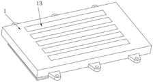
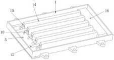
本发明一种新能源电池防护装置,包括电池安装座和位于电池安装座上方的蓄电池本体,所述蓄电池本体的外部固定有安装环,且安装环通过螺栓固定在电池安装座的上表面,电池安装座为矩形空腔结构,电池安装座底壁的一侧活动设置有活动板一,电池安装座底壁的另一侧开设有多个散热孔,活动板一的下表面对称固定有连接柱,两根连接柱的底端共同固定有活动板二,活动板一和活动板二之间固定有多个进风筒,进风筒的一端设置有防尘网,进风筒的另一端连接有进风管,且进风管的一端伸入电池安装座内,活动板一的上表面对称固定有挡杆,电池安装座的顶壁上安装有多个导热板,导热板的底壁上固定有散热条。The invention provides a new energy battery protection device, comprising a battery mounting seat and a battery body located above the battery mounting seat, a mounting ring is fixed on the outside of the battery body, and the mounting ring is fixed on the upper surface of the battery mounting seat by bolts, and the battery The mounting seat has a rectangular cavity structure, a
作为本发明的一种优选技术方案,所述电池安装座的两侧壁上均固定有多个安装耳,且安装耳上开设有安装孔。As a preferred technical solution of the present invention, a plurality of mounting ears are fixed on both side walls of the battery mounting seat, and mounting holes are opened on the mounting ears.
作为本发明的一种优选技术方案,所述散热条数量与进风管的数量相同,散热条的底端固定在电池安装座的底壁上,散热条上沿长度方向开设有通风孔,进风管伸入电池安装座内的一端固定在通风孔内。As a preferred technical solution of the present invention, the number of the heat dissipation strips is the same as the number of the air inlet pipes, the bottom end of the heat dissipation strip is fixed on the bottom wall of the battery mounting seat, and the heat dissipation strip is provided with ventilation holes along the length direction, and the intake The end of the air duct extending into the battery mounting seat is fixed in the ventilation hole.
作为本发明的一种优选技术方案,所述电池安装座的底壁上固定有通风箱,通风箱靠近散热条的侧壁上均匀开设有多个进风孔,且多个进风孔分别与多个通风孔相对应,通风箱的底壁上开设有多个出风孔,且多个出风孔分别与多个散热孔相对应。As a preferred technical solution of the present invention, a ventilation box is fixed on the bottom wall of the battery mounting seat, and a plurality of air inlet holes are evenly opened on the side wall of the ventilation box close to the heat dissipation strip, and the plurality of air inlet holes are respectively connected with The plurality of ventilation holes correspond to each other, and the bottom wall of the ventilation box is provided with a plurality of air outlet holes, and the plurality of air outlet holes correspond to the plurality of heat dissipation holes respectively.
作为本发明的一种优选技术方案,所述电池安装座顶壁的内表面对称安装有电动推杆,电动推杆的输出轴末端连接有拉绳,电池安装座顶壁的内表面对称安装有固定环,两根拉绳的一端分别穿过两个固定环,且两根拉绳穿过固定环的一端均与活动板一连接。As a preferred technical solution of the present invention, an electric push rod is symmetrically installed on the inner surface of the top wall of the battery mounting seat, the end of the output shaft of the electric push rod is connected with a pulling rope, and the inner surface of the top wall of the battery mounting seat is symmetrically installed with a pull rope. In the fixing ring, one end of the two pulling ropes respectively passes through the two fixing rings, and one end of the two pulling ropes passing through the fixing ring is connected with the movable plate.
作为本发明的一种优选技术方案,所述电池安装座底壁的内表面安装有温度传感器,电池安装座的一侧内壁上安装有控制器,温度传感器与控制器电性连接,控制器与电动推杆电性连接。As a preferred technical solution of the present invention, a temperature sensor is installed on the inner surface of the bottom wall of the battery installation seat, a controller is installed on one inner wall of the battery installation seat, the temperature sensor is electrically connected with the controller, and the controller is connected with The electric actuator is electrically connected.
本发明的有益效果是:The beneficial effects of the present invention are:
1、通过设置活动板一、活动板二、进风筒、防尘网、进风管、导热板和散热条等结构,行车行进时,外界的冷空气通过进风筒和进风管进入电池安装座的内部,导热板接蓄电池本体的底部接触,吸收蓄电池本体工作时产生的热量,散热条将导热板的热量吸收,冷空气的气流将散热条的热量带走并通过散热孔排出,有效的对蓄电池本体进行散热防护,且结构设置在电池安装座内,不会占用多余的空间,更不需要额外的能耗,保证蓄电池本体的使用寿命;1. By setting
2、通过在散热条上设置通风孔,将进风管的一端固定在通风孔内,使气流的路线固定,气流充分与散热条接触,不仅提高了散热效果,利用散热条的辐射,也提高了导热板的吸热效果;2. By setting ventilation holes on the heat dissipation strip, one end of the air inlet pipe is fixed in the ventilation hole, so that the air flow path is fixed, and the air flow is fully in contact with the heat dissipation strip, which not only improves the heat dissipation effect, but also improves the heat dissipation effect by using the radiation of the heat dissipation strip. The heat-absorbing effect of the heat-conducting plate;
3、通过设置通风箱,使气流带走的热量可快速排至电池安装座的外部,充分降低电池安装座内的温度,进一步提高散热效果;3. By setting the ventilation box, the heat taken by the airflow can be quickly discharged to the outside of the battery mount, fully reducing the temperature in the battery mount, and further improving the heat dissipation effect;
4、通过设置电动推杆、拉绳和固定环,在汽车停止或冬季气温低,蓄电池本体不需要散热的情况下,可将活动板一和活动板二收纳至电池安装座的内部,不必使设备一直暴露在外部,也延长了设备的使用寿命,同时活动板二也可使电池安装座整体保持平整。4. By setting the electric push rod, pulling rope and fixing ring, when the car is stopped or the temperature is low in winter, and the battery body does not need heat dissipation, the
附图说明Description of drawings
附图用来提供对本发明的进一步理解,并且构成说明书的一部分,与本发明的实施例一起用于解释本发明,并不构成对本发明的限制。在附图中:The accompanying drawings are used to provide a further understanding of the present invention, and constitute a part of the specification, and are used to explain the present invention together with the embodiments of the present invention, and do not constitute a limitation to the present invention. In the attached image:
图1是本发明的结构示意图一;Fig. 1 is the structural representation one of the present invention;
图2是本发明的结构示意图二;Fig. 2 is the structural representation two of the present invention;
图3是图2中A处的放大图;Fig. 3 is the enlarged view of A place in Fig. 2;
图4是本发明的电池安装座的结构示意图;4 is a schematic structural diagram of a battery mounting seat of the present invention;
图5是本发明的进风管和散热条的结构示意图;5 is a schematic structural diagram of an air inlet pipe and a heat dissipation strip of the present invention;
图6是本发明的通风箱的立体结构示意图;Fig. 6 is the three-dimensional structure schematic diagram of the ventilation box of the present invention;
图7是本发明的电池安装座的剖视图。7 is a cross-sectional view of the battery mount of the present invention.
图中:1、电池安装座;2、蓄电池本体;3、安装环;4、安装耳;5、活动板一;6、连接柱;7、活动板二;8、进风筒;9、防尘网;10、进风管;11、散热孔;12、挡杆;13、导热板;14、散热条;15、通风孔;16、通风箱;17、进风孔;18、出风孔;19、电动推杆;20、拉绳;21、固定环;22、温度传感器;23、控制器。In the picture: 1. Battery mounting seat; 2. Battery body; 3. Mounting ring; 4. Mounting ears; 5.
具体实施方式Detailed ways
下面将结合本申请实施例中的附图,对本申请实施例中的技术方案进行清楚、完整地描述,显然,所描述的实施例仅仅是本申请一部分实施例,而不是全部的实施例。The technical solutions in the embodiments of the present application will be clearly and completely described below with reference to the drawings in the embodiments of the present application. Obviously, the described embodiments are only a part of the embodiments of the present application, but not all of the embodiments.
请参阅图1-5所示,一种新能源电池防护装置,包括电池安装座1和位于电池安装座1上方的蓄电池本体2,蓄电池本体2的外部固定有安装环3,且安装环3通过螺栓固定在电池安装座1的上表面,电池安装座1为矩形空腔结构,电池安装座1底壁的一侧活动设置有活动板一5,电池安装座1底壁的另一侧开设有多个散热孔11,活动板一5的下表面对称固定有连接柱6,两根连接柱6的底端共同固定有活动板二7,活动板一5和活动板二7之间固定有多个进风筒8,进风筒8的一端设置有防尘网9,进风筒8的另一端连接有进风管10,且进风管10的一端伸入电池安装座1内,活动板一5的上表面对称固定有挡杆12,电池安装座1的顶壁上安装有多个导热板13,导热板13的底壁上固定有散热条14。1-5, a new energy battery protection device includes a
工作过程:蓄电池本体2安装在电池安装座1上,蓄电池本体2的底部接触导热板13,然后利用举升机将设备举升至新能源汽车的底盘处进行安装即可,在活动板一5和活动板二7之间设置有多个进风筒8,挡杆12可避免活动板一5从电池安装座1上脱落,在汽车行进时,外界的冷空气通过进风筒8和进风管10进入电池安装座1的内部,进风筒8上的防尘网9可避免灰尘进入电池安装座1内,导热板13吸收蓄电池本体2工作时产生的热量,散热条14将导热板13的热量吸收,冷空气的气流将散热条14的热量带走并通过散热孔11排出,有效的对蓄电池本体2进行散热防护,且结构设置在电池安装座1内,不会占用多余的空间,更不需要额外的能耗,保证蓄电池本体2的使用寿命。Working process: The
请参阅图1-2所示,电池安装座1的两侧壁上均固定有多个安装耳4,且安装耳4上开设有安装孔;通过安装耳4可方便将电池安装座1固定在汽车的底盘处。Referring to Figure 1-2, a plurality of mounting
请参阅图5所示,散热条14数量与进风管10的数量相同,散热条14的底端固定在电池安装座1的底壁上,散热条14上沿长度方向开设有通风孔15,进风管10伸入电池安装座1内的一端固定在通风孔15内;将进风管10的一端固定在通风孔15内,使气流的路线固定,气流充分与散热条14接触,不仅提高了散热效果,利用散热条14的辐射,也提高了导热板13的吸热效果。Please refer to FIG. 5 , the number of heat dissipation strips 14 is the same as that of the
请参阅图5-6所示,电池安装座1的底壁上固定有通风箱16,通风箱16靠近散热条14的侧壁上均匀开设有多个进风孔17,且多个进风孔17分别与多个通风孔15相对应,通风箱16的底壁上开设有多个出风孔18,且多个出风孔18分别与多个散热孔11相对应;气流通过通风孔15和进风孔17直接进入通风箱16内,再通过出风孔18和散热孔11排至电池安装座1的外部,气流的路线固定,使热量可快速排出,进一步提高散热效果。Please refer to FIGS. 5-6 , a
请参阅图7所示,电池安装座1顶壁的内表面对称安装有电动推杆19,电动推杆19的输出轴末端连接有拉绳20,电池安装座1顶壁的内表面对称安装有固定环21,两根拉绳20的一端分别穿过两个固定环21,且两根拉绳20穿过固定环21的一端均与活动板一5连接;在汽车停止或冬季气温低,蓄电池本体2不需要散热的情况下,可将活动板一5和活动板二7收纳至电池安装座1的内部,不必使设备一直暴露在外部,也延长了设备的使用寿命,同时活动板二7与电池安装座1的底部齐平,可使电池安装座1整体保持平整。Please refer to FIG. 7 , an
请参阅图7所示,电池安装座1底壁的内表面安装有温度传感器22,电池安装座1的一侧内壁上安装有控制器23,温度传感器22与控制器23电性连接,控制器23与电动推杆19电性连接;利用温度传感器22实时监测电池安装座1内的温度,当温度传感器22监测的温度较低时,进风筒8收纳在电池安装座1的内部,当温度传感器22检测的温度较高后,将信号传递给控制器23,控制器23控制电动推杆19启动,将活动板二7下放至电池安装座1的外部,为保证下放过程中的平稳,可降低车速或暂时将车停在路边,待活动板二7完全下降再正常行驶汽车,避免下放过程中气流过大使活动板二7无法平稳下放。Referring to FIG. 7 , a
工作原理:使用时,将蓄电池本体2通过螺栓安装在电池安装座1上,然后利用举升机将电池安装座1提升至汽车底盘的下方,电池安装座1的安装耳4与汽车底盘上的安装对齐,然后进行安装即可,利用温度传感器22实时监测电池安装座1内的温度,当温度传感器22监测的温度较低时,进风筒8收纳在电池安装座1的内部,当温度传感器22检测的温度较高后,将信号传递给控制器23,控制器23控制电动推杆19启动,电动推杆19的输出轴向左移动,带动拉绳20向左移动,将活动板二7下放至电池安装座1的外部,为保证下放过程中的平稳,可降低车速或暂时将车停在路边,待活动板二7完全下降再正常行驶汽车,避免下放过程中气流过大使活动板二7无法平稳下放,活动板一5上设置有挡杆12,可避免活动板一5脱离电池安装座1,活动板一5和挡杆12卡在电池安装座1的底壁上,稳定性好;Working principle: When in use, install the
汽车行驶过程中,外界的冷空气通过进风筒8和进风管10进入电池安装座1的内部,进风筒8上的防尘网9可避免灰尘进入电池安装座1内,导热板13吸收蓄电池本体2工作时产生的热量,散热条14将导热板13的热量吸收,进风管10的一端固定在通风孔15内,使气流的路线固定,气流充分与散热条14接触,冷空气的气流将散热条14的热量带走,气流通过通风孔15和进风孔17直接进入通风箱16内,再通过出风孔18和散热孔11排至电池安装座1的外部,气流的路线固定,使热量可快速排出,有效的对蓄电池本体2进行散热防护,整体结构设置在电池安装座1内以及下方,不会占用多余的空间,更不需要额外的能耗,仅仅是电动推杆19工作时消耗部分电能,保证蓄电池本体2的使用寿命。During the driving process of the car, the cold air from the outside enters the interior of the
以上所述仅为本发明的优选实施例而已,并不用于限制本发明,尽管参照前述实施例对本发明进行了详细的说明,对于本领域的技术人员来说,其依然可以对前述各实施例所记载的技术方案进行修改,或者对其中部分技术特征进行等同替换。凡在本发明的精神和原则之内,所作的任何修改、等同替换、改进等,均应包含在本发明的保护范围之内。The above descriptions are only preferred embodiments of the present invention, and are not intended to limit the present invention. Although the present invention has been described in detail with reference to the foregoing embodiments, those skilled in the art can still understand the foregoing embodiments. The technical solutions described are modified, or some technical features thereof are equivalently replaced. Any modification, equivalent replacement, improvement, etc. made within the spirit and principle of the present invention shall be included within the protection scope of the present invention.
Claims (6)
Priority Applications (1)
| Application Number | Priority Date | Filing Date | Title |
|---|---|---|---|
| CN202210530363.0ACN114744335A (en) | 2022-05-16 | 2022-05-16 | New energy battery protector |
Applications Claiming Priority (1)
| Application Number | Priority Date | Filing Date | Title |
|---|---|---|---|
| CN202210530363.0ACN114744335A (en) | 2022-05-16 | 2022-05-16 | New energy battery protector |
Publications (1)
| Publication Number | Publication Date |
|---|---|
| CN114744335Atrue CN114744335A (en) | 2022-07-12 |
Family
ID=82284894
Family Applications (1)
| Application Number | Title | Priority Date | Filing Date |
|---|---|---|---|
| CN202210530363.0APendingCN114744335A (en) | 2022-05-16 | 2022-05-16 | New energy battery protector |
Country Status (1)
| Country | Link |
|---|---|
| CN (1) | CN114744335A (en) |
Citations (4)
| Publication number | Priority date | Publication date | Assignee | Title |
|---|---|---|---|---|
| CN206711998U (en)* | 2017-05-09 | 2017-12-05 | 华北电力大学科技学院 | A kind of heat abstractor for batteries of electric automobile |
| CN108520987A (en)* | 2018-04-03 | 2018-09-11 | 余瑞梅 | A temperature-adjustable electric vehicle battery assembly |
| CN108520932A (en)* | 2018-06-14 | 2018-09-11 | 北京科易动力科技有限公司 | Battery pack and vehicle with same |
| CN113300022A (en)* | 2021-05-21 | 2021-08-24 | 高鸿杰 | Heat exchange module and heat exchange method of new energy automobile |
- 2022
- 2022-05-16CNCN202210530363.0Apatent/CN114744335A/enactivePending
Patent Citations (4)
| Publication number | Priority date | Publication date | Assignee | Title |
|---|---|---|---|---|
| CN206711998U (en)* | 2017-05-09 | 2017-12-05 | 华北电力大学科技学院 | A kind of heat abstractor for batteries of electric automobile |
| CN108520987A (en)* | 2018-04-03 | 2018-09-11 | 余瑞梅 | A temperature-adjustable electric vehicle battery assembly |
| CN108520932A (en)* | 2018-06-14 | 2018-09-11 | 北京科易动力科技有限公司 | Battery pack and vehicle with same |
| CN113300022A (en)* | 2021-05-21 | 2021-08-24 | 高鸿杰 | Heat exchange module and heat exchange method of new energy automobile |
Similar Documents
| Publication | Publication Date | Title |
|---|---|---|
| CN107293667B (en) | New energy automobile battery box | |
| CN112259828B (en) | New energy automobile battery package heat abstractor | |
| CN114744335A (en) | New energy battery protector | |
| CN207602737U (en) | A kind of battery air cooling equipment of new-energy automobile | |
| CN222621437U (en) | Fire control cabinet of patrolling and examining | |
| CN213905502U (en) | High lithium cell of security | |
| CN211406724U (en) | Heat dissipation device for motor controller of pure electric vehicle | |
| CN216698495U (en) | A large photovoltaic new energy battery cooling device | |
| CN216085125U (en) | Battery protective housing for new energy automobile | |
| CN216697107U (en) | Intelligent dispatching desk for power system | |
| CN114571977A (en) | Non-bearing type chassis for high-protection type new energy automobile for battery | |
| CN210161887U (en) | Electric automobile lithium cell that radiating effect is good | |
| CN221708783U (en) | New energy battery supporting structure with good heat dissipation effect | |
| CN212157005U (en) | A solar LED street light with efficient heat dissipation | |
| CN208014864U (en) | A kind of underlying air duct and subregion heat dissipation battery cooling device | |
| CN222514947U (en) | A new energy vehicle lithium battery protection structure | |
| CN220065803U (en) | Cooling component and lithium battery pack for electric loader | |
| CN219998333U (en) | New forms of energy power end plate battery compartment cooling device | |
| CN212571183U (en) | New energy automobile battery watertight fittings | |
| CN205883806U (en) | Power transmission is heat abstractor for equipment | |
| CN222654132U (en) | Storage battery with heat radiation structure | |
| CN212650002U (en) | Storage battery car controller convenient to heat dissipation | |
| CN216287725U (en) | A wear-resistant and heat-dissipating new energy vehicle charging cable | |
| CN115009936B (en) | Open type mooring box with built-in control unit and winding roller | |
| CN216564892U (en) | Heat dissipation high pressure four-quadrant converter |
Legal Events
| Date | Code | Title | Description |
|---|---|---|---|
| PB01 | Publication | ||
| PB01 | Publication | ||
| SE01 | Entry into force of request for substantive examination | ||
| SE01 | Entry into force of request for substantive examination |