CN114740434A - Equidistance distribution subarray system and method for resisting accompanying interference - Google Patents
Equidistance distribution subarray system and method for resisting accompanying interferenceDownload PDFInfo
- Publication number
- CN114740434A CN114740434ACN202210225404.5ACN202210225404ACN114740434ACN 114740434 ACN114740434 ACN 114740434ACN 202210225404 ACN202210225404 ACN 202210225404ACN 114740434 ACN114740434 ACN 114740434A
- Authority
- CN
- China
- Prior art keywords
- target
- interference
- angle
- range
- subarray
- Prior art date
- Legal status (The legal status is an assumption and is not a legal conclusion. Google has not performed a legal analysis and makes no representation as to the accuracy of the status listed.)
- Granted
Links
- 238000000034methodMethods0.000titleclaimsabstractdescription47
- 238000001514detection methodMethods0.000claimsabstractdescription38
- 238000005457optimizationMethods0.000claimsabstractdescription13
- 239000013598vectorSubstances0.000claimsdescription33
- 238000012545processingMethods0.000claimsdescription23
- 238000003491arrayMethods0.000claimsdescription21
- 238000005259measurementMethods0.000claimsdescription18
- 230000001629suppressionEffects0.000claimsdescription17
- 239000011159matrix materialSubstances0.000claimsdescription16
- 238000001914filtrationMethods0.000claimsdescription14
- 238000007781pre-processingMethods0.000claimsdescription12
- 230000008569processEffects0.000claimsdescription11
- 238000002592echocardiographyMethods0.000claimsdescription10
- 238000005070samplingMethods0.000claimsdescription6
- 239000000969carrierSubstances0.000claimsdescription4
- 238000004458analytical methodMethods0.000abstractdescription5
- 238000004088simulationMethods0.000abstractdescription4
- 230000010365information processingEffects0.000abstractdescription2
- 238000009795derivationMethods0.000abstract1
- 238000000926separation methodMethods0.000abstract1
- 230000000875corresponding effectEffects0.000description21
- 238000010586diagramMethods0.000description8
- 230000002452interceptive effectEffects0.000description7
- 238000013461designMethods0.000description3
- 238000003672processing methodMethods0.000description3
- 230000003595spectral effectEffects0.000description3
- 238000001228spectrumMethods0.000description3
- 230000009471actionEffects0.000description2
- 230000003044adaptive effectEffects0.000description2
- 230000008859changeEffects0.000description2
- 230000000694effectsEffects0.000description2
- 230000006872improvementEffects0.000description2
- 238000000342Monte Carlo simulationMethods0.000description1
- 230000004075alterationEffects0.000description1
- 238000013459approachMethods0.000description1
- 230000009286beneficial effectEffects0.000description1
- 230000000052comparative effectEffects0.000description1
- 239000002131composite materialSubstances0.000description1
- 238000009833condensationMethods0.000description1
- 230000005494condensationEffects0.000description1
- 230000002596correlated effectEffects0.000description1
- 230000007812deficiencyEffects0.000description1
- 229910003460diamondInorganic materials0.000description1
- 239000010432diamondSubstances0.000description1
- 238000012986modificationMethods0.000description1
- 230000004048modificationEffects0.000description1
- 238000011160researchMethods0.000description1
- 238000006467substitution reactionMethods0.000description1
Images


Classifications
- G—PHYSICS
- G01—MEASURING; TESTING
- G01S—RADIO DIRECTION-FINDING; RADIO NAVIGATION; DETERMINING DISTANCE OR VELOCITY BY USE OF RADIO WAVES; LOCATING OR PRESENCE-DETECTING BY USE OF THE REFLECTION OR RERADIATION OF RADIO WAVES; ANALOGOUS ARRANGEMENTS USING OTHER WAVES
- G01S7/00—Details of systems according to groups G01S13/00, G01S15/00, G01S17/00
- G01S7/02—Details of systems according to groups G01S13/00, G01S15/00, G01S17/00 of systems according to group G01S13/00
- G01S7/28—Details of pulse systems
- G01S7/2813—Means providing a modification of the radiation pattern for cancelling noise, clutter or interfering signals, e.g. side lobe suppression, side lobe blanking, null-steering arrays
- G—PHYSICS
- G01—MEASURING; TESTING
- G01S—RADIO DIRECTION-FINDING; RADIO NAVIGATION; DETERMINING DISTANCE OR VELOCITY BY USE OF RADIO WAVES; LOCATING OR PRESENCE-DETECTING BY USE OF THE REFLECTION OR RERADIATION OF RADIO WAVES; ANALOGOUS ARRANGEMENTS USING OTHER WAVES
- G01S7/00—Details of systems according to groups G01S13/00, G01S15/00, G01S17/00
- G01S7/02—Details of systems according to groups G01S13/00, G01S15/00, G01S17/00 of systems according to group G01S13/00
- G01S7/28—Details of pulse systems
- G01S7/285—Receivers
- G01S7/292—Extracting wanted echo-signals
- G01S7/2923—Extracting wanted echo-signals based on data belonging to a number of consecutive radar periods
- G01S7/2928—Random or non-synchronous interference pulse cancellers
- G—PHYSICS
- G01—MEASURING; TESTING
- G01S—RADIO DIRECTION-FINDING; RADIO NAVIGATION; DETERMINING DISTANCE OR VELOCITY BY USE OF RADIO WAVES; LOCATING OR PRESENCE-DETECTING BY USE OF THE REFLECTION OR RERADIATION OF RADIO WAVES; ANALOGOUS ARRANGEMENTS USING OTHER WAVES
- G01S7/00—Details of systems according to groups G01S13/00, G01S15/00, G01S17/00
- G01S7/02—Details of systems according to groups G01S13/00, G01S15/00, G01S17/00 of systems according to group G01S13/00
- G01S7/36—Means for anti-jamming, e.g. ECCM, i.e. electronic counter-counter measures
- Y—GENERAL TAGGING OF NEW TECHNOLOGICAL DEVELOPMENTS; GENERAL TAGGING OF CROSS-SECTIONAL TECHNOLOGIES SPANNING OVER SEVERAL SECTIONS OF THE IPC; TECHNICAL SUBJECTS COVERED BY FORMER USPC CROSS-REFERENCE ART COLLECTIONS [XRACs] AND DIGESTS
- Y02—TECHNOLOGIES OR APPLICATIONS FOR MITIGATION OR ADAPTATION AGAINST CLIMATE CHANGE
- Y02D—CLIMATE CHANGE MITIGATION TECHNOLOGIES IN INFORMATION AND COMMUNICATION TECHNOLOGIES [ICT], I.E. INFORMATION AND COMMUNICATION TECHNOLOGIES AIMING AT THE REDUCTION OF THEIR OWN ENERGY USE
- Y02D30/00—Reducing energy consumption in communication networks
- Y02D30/70—Reducing energy consumption in communication networks in wireless communication networks
Landscapes
- Engineering & Computer Science (AREA)
- Radar, Positioning & Navigation (AREA)
- Remote Sensing (AREA)
- Computer Networks & Wireless Communication (AREA)
- Physics & Mathematics (AREA)
- General Physics & Mathematics (AREA)
- Radar Systems Or Details Thereof (AREA)
Abstract
Description
Translated fromChinese技术领域technical field
本发明属于雷达信号与信息处理技术领域,具体涉及一种等距分布子阵列系统及抗伴飞式干扰的方法。The invention belongs to the technical field of radar signal and information processing, and in particular relates to an equidistantly distributed sub-array system and a method for anti-flying interference.
背景技术Background technique
伴飞式干扰(问题P1)通常由拖曳式或投掷式有源干扰设备产生,其干扰载体通常与战机共同处于主瓣内并存在一定的角度差异。运用主瓣干扰对消技术(MLC)可控制天线方向图在主瓣干扰方向形成凹口,从而实现对该类干扰增益置零。然而,在空地电子对抗过程中,战机通过运用战术、技术手段可有效压缩其与干扰设备之间的角度差异,使其亦处于主瓣方向图凹口方向,导致雷达系统大幅度地降低对战机的检测与跟踪性能。若天线系统采用大型阵列天线,主瓣凹口宽度将显著降低,当天线孔径足够大时,主瓣凹口将不再覆盖战机方向,从而使得雷达系统可以实现对战机的检测与跟踪。然而,运用稀疏孔径技术构建大型阵列天线具有阵元数量多、难以机动的特点,难以满足车载雷达设计需求。Accompanying jamming (problem P1) is usually produced by towed or thrown active jamming equipment, and its jamming carrier is usually co-located with the fighter in the main lobe and has a certain angle difference. The main lobe interference cancellation technology (MLC) can be used to control the antenna pattern to form a notch in the main lobe interference direction, so as to achieve zero gain for this type of interference. However, in the process of air-to-ground electronic countermeasures, the fighter can effectively compress the angle difference between it and the jamming equipment by using tactics and technical means, so that it is also in the direction of the notch of the main lobe pattern, which causes the radar system to greatly reduce the countermeasures of the fighter. detection and tracking performance. If the antenna system adopts a large array antenna, the width of the main lobe notch will be significantly reduced. When the antenna aperture is large enough, the main lobe notch will no longer cover the direction of the fighter, so that the radar system can detect and track the fighter. However, the use of sparse aperture technology to construct large-scale array antennas has the characteristics of large number of array elements and difficulty in maneuvering, which is difficult to meet the design requirements of vehicle radar.
由目前的稀疏阵列优化算法可知,这些算法在优化主瓣、旁瓣电平及阵列稀疏度的同时抑制了天线方向图栅瓣,无栅瓣方向图在主瓣方向上的天线增益远高于其它方向,运用该特性进行目标检测不会出现角度模糊问题,使得该类天线可以较容易地确定目标方向。然而,对于相同的主瓣宽度,无栅瓣阵列通常比有栅瓣阵列需要设置更多的天线阵元,对于大型阵列天线(孔径达到数十米或更大),两种阵列样式的阵元数量差异将变得尤为显著。为了进一步降低天线系统阵元数,我们提出了等距分布子阵列抗伴飞式干扰技术。It can be seen from the current sparse array optimization algorithms that these algorithms suppress the grating lobe of the antenna pattern while optimizing the main lobe, side lobe level and array sparsity, and the antenna gain in the main lobe direction without grating lobe pattern is much higher than In other directions, using this feature for target detection will not cause the problem of angular ambiguity, so that this type of antenna can easily determine the target direction. However, for the same main lobe width, the grating-lobe-free array usually requires more antenna elements than the grating-lobe array. Quantitative differences will become even more pronounced. In order to further reduce the number of array elements of the antenna system, we propose an equidistantly distributed sub-array anti-flying interference technology.
等距分布子阵列(uniformly distributed sub arrays,UDSA)是一种典型的阵列样式,此处设置系统内各子阵列具有相同的阵列结构且子阵间距远大于半波。由阵列信号处理理论可知,当该系统各阵元具有相同的方向图时,其合成方向图将具有一个主瓣和多个栅瓣,且其栅瓣分布具有较强的规律性。进一步分析可知,该系统主瓣宽度由其总跨度决定,在该系统子阵数量固定条件下,可通过增加子阵间距提升主瓣分辨能力,该特性对于分辨主瓣内的目标与伴飞式干扰信号具有重要意义。然而,当子阵列间距增加时(总跨度达数十米以上),该系统将面临若干需要处理的技术问题:首先,传统的窄带雷达信号在大尺度阵列上不再保持“窄带特性”,即目标回波频带内各频点导向矢量不再相同,因此该系统需要在时频域对各路接收信号作预处理使其满足分布式天线对信号带宽的限制;其次,为了保证在外部干扰抑制过程中不破坏系统栅瓣规律性,该系统需要在各个子阵上设计相同的干扰抑制滤波器滤除旁瓣干扰,并需要保证主瓣干扰和目标获得足够增益;最后,阵列方向图栅瓣会导致角度测量模糊,需要给出相应的解决方案。Uniformly distributed sub-arrays (uniformly distributed sub-arrays, UDSA) are a typical array pattern, where each sub-array in the system has the same array structure and the sub-array spacing is much larger than half-wave. According to the array signal processing theory, when each array element of the system has the same pattern, its composite pattern will have one main lobe and multiple grating lobes, and the grating lobe distribution has strong regularity. Further analysis shows that the main lobe width of the system is determined by its total span. Under the condition that the number of sub-arrays in the system is fixed, the main lobe resolution can be improved by increasing the sub-array spacing. Interfering signals are important. However, when the sub-array spacing increases (the total span is more than tens of meters), the system will face several technical problems that need to be dealt with: First, the traditional narrow-band radar signal no longer maintains "narrow-band characteristics" on large-scale arrays, that is, The steering vectors of each frequency point in the target echo frequency band are no longer the same, so the system needs to preprocess each received signal in the time-frequency domain to make it meet the signal bandwidth limitation of the distributed antenna; secondly, in order to ensure the suppression of external interference In the process, the regularity of the grating lobe of the system is not destroyed. The system needs to design the same interference suppression filter on each sub-array to filter out the side lobe interference, and it is necessary to ensure that the main lobe interference and the target obtain sufficient gain; finally, the array pattern grating lobe It will cause the angle measurement to be blurred, and a corresponding solution needs to be given.
发明内容SUMMARY OF THE INVENTION
本发明的目的在于克服现有技术的不足,提供一种等距分布子阵列系统及抗伴飞式干扰的方法。The purpose of the present invention is to overcome the deficiencies of the prior art, and to provide an equidistantly distributed sub-array system and a method for anti-flying interference.
本发明的第一个目的是提供一种等距分布子阵列抗伴飞式干扰的方法,包括以下步骤:A first object of the present invention is to provide a method for equidistantly distributed sub-arrays against accompanying flying interference, comprising the following steps:
S1、将等距分布子阵列系统中各天线输入的目标回波及多个干扰信号进行时频域预处理滤至相同的窄带范围内,使得系统输入信号满足窄带条件,窄带范围内方向为θ的目标导向矢量可表示为:S1. Perform time-frequency domain preprocessing on the target echoes and multiple interference signals input by each antenna in the equidistantly distributed sub-array system to the same narrowband range, so that the system input signal satisfies the narrowband condition, and the direction in the narrowband range is θ. The goal-directed vector can be expressed as:

其中,


其中,θ为角度,λ为探测信号波长,d为阵元间距,L为阵列间距,M为子阵数量,N为子阵上的阵元数量;Among them, θ is the angle, λ is the wavelength of the detection signal, d is the array element spacing, L is the array spacing, M is the number of sub-arrays, and N is the number of array elements on the sub-array;
S2、对步骤S1经过预处理的目标回波及多个干扰信号进行空域滤波处理,接着将处理过的目标回波及多个干扰信号输入到等距分布子阵列系统中的各子阵中,各子阵运用相同的旁瓣干扰抑制滤波器对各子阵的旁瓣干扰进行抑制,抑制过程中对主瓣进行保形,各子阵滤除旁瓣干扰后,输出的目标回波及多个干扰信号可表示为:S2. Perform spatial filtering processing on the preprocessed target echo and multiple interference signals in step S1, and then input the processed target echo and multiple interference signals into each sub-array in the equidistantly distributed sub-array system. The array uses the same side lobe interference suppression filter to suppress the side lobe interference of each sub-array, and the main lobe is kept in shape during the suppression process. After each sub-array filters out the side lobe interference, the output target echo and multiple interference signals can be expressed as:

其中,wSLC为子阵空域滤波器,IM×M为单位矩阵,zd为旁瓣对消器输出信号,z为旁瓣对消器输入信号;Among them, wSLC is the sub-array spatial domain filter, IM×M is the identity matrix, zd is the output signal of the side lobe canceller, and z is the input signal of the side lobe canceller;
S3、通过稀疏检测模型对子阵间的各步骤S2输出的目标回波及多个干扰信号实现目标信号检测,并运用如下优化方法对其进行求解:S3. The sparse detection model is used to detect the target echoes and multiple interference signals output by each step S2 between the sub-arrays, and the following optimization method is used to solve them:

其中,Φ为传感矩阵,且Φ=[ad(sinθ0),ad(sinθ1),…,ad(sinθI-1)],导向矢量ad(sinθ)在sinθ域以λ/L为周期,为了避免传感矩阵列向量重复,此处在一个周期内取I个导向矢量,每个矢量对应的角度θi满足如下关系:Among them, Φ is the sensing matrix, and Φ=[ad (sinθ0 ), ad (sinθ1 ), ..., ad (sinθI-1 )], the steering vector ad( sinθ) is in the sinθ domain with λ /L is the period. In order to avoid the repetition of the column vector of the sensing matrix, I take one steering vector in one period, and the angle θi corresponding to each vector satisfies the following relationship:
θi=arcsinξi,θi = arcsinξi ,
ξi=ξ0+iΔ,0≤i≤I-1,ξi =ξ0 +iΔ, 0≤i≤I-1,

其中,θ0是子阵波束中心指向,ξ0=sinθ0,对应于波束中心指正的参考正弦值,各角度正弦值ξi构成等差数列,差值为Δ,其中I为角度采样数,λ为波长,此时无模糊测量区间范围为θ∈[θ0,θu),其中
S4、通过频率捷变(FA)技术在不同的载频上对步骤S3得到的同一个目标的角度x进行多次测量并获取各自的余数,不同载频对应的余数集合之间的关系满足如下同余方程组:S4. The angle x of the same target obtained in step S3 is measured multiple times on different carrier frequencies through the frequency agility (FA) technology and the respective remainders are obtained. The relationship between the remainder sets corresponding to different carrier frequencies satisfies the following System of congruence equations:

其中,K代表FA过程中的不同载波数量,Ik为无模糊角度采样个数;Among them, K represents the number of different carriers in the FA process, and Ik is the number of unambiguous angle samples;
S5、基于模糊坐标聚类算法对步骤S4中的目标角度坐标xk进行处理,得到目标坐标均值。S5. Process the target angle coordinate xk in step S4 based on the fuzzy coordinate clustering algorithm to obtain the mean value of the target coordinate.
优选的,步骤S1中,所述时频域预处理包括以下步骤:Preferably, in step S1, the time-frequency domain preprocessing includes the following steps:
为等距分布子阵列系统中的各天线接收机分别设置了一组相互毗邻、并覆盖全距离段的距离选通信号,每个距离选通信号宽度按照雷达距离分辨力设定,并为每个距离选通信号对应设置一个窄带滤波器,使各窄带滤波器工作在相同频点,当关注的目标速度未知时,该频点设置于零多普勒频移处,当速度已存在估计值时,频点设置于相应的多普勒频移处,各天线接收机接收到的多普勒频移不敏感的目标回波及多个干扰信号通过对应的距离选通信号以及窄带滤波器滤波至相同的窄带范围内。For each antenna receiver in the equidistantly distributed sub-array system, a set of range gating signals adjacent to each other and covering the whole range are respectively set up. The width of each range gating signal is set according to the radar range resolution, and is set for each A narrowband filter is set corresponding to each range gating signal, so that each narrowband filter works at the same frequency point. When the speed of the target concerned is unknown, the frequency point is set at the zero Doppler frequency shift. When the speed has an estimated value When the frequency point is set at the corresponding Doppler frequency shift, the target echoes and multiple interference signals that are not sensitive to Doppler frequency shift received by each antenna receiver are filtered by the corresponding range gating signal and narrowband filter to within the same narrowband range.
优选的,步骤S1中,所述时频域预处理包括以下步骤:Preferably, in step S1, the time-frequency domain preprocessing includes the following steps:
为等距分布子阵列系统中的各天线接收机分别设置了一组相互毗邻、并覆盖全距离段的距离选通信号,每个距离选通信号宽度按照雷达距离分辨力设定,并为每个距离选通信号对应设置一组滤波器组,滤波器组的频率覆盖范围与目标信号的无模糊测频范围相同,各天线接收机接收到的多普勒频移敏感的目标回波及多个干扰信号通过对应的距离选通信号以及窄带滤波器滤波至相同的窄带范围内。For each antenna receiver in the equidistantly distributed sub-array system, a set of range gating signals adjacent to each other and covering the whole range are respectively set up. The width of each range gating signal is set according to the radar range resolution, and is set for each A set of filter banks is set corresponding to each range gating signal. The frequency coverage of the filter bank is the same as the unambiguous frequency measurement range of the target signal. The Doppler frequency shift-sensitive target echo received by each antenna receiver and multiple The interfering signal is filtered into the same narrowband range by the corresponding range gating signal and the narrowband filter.
优选的,步骤S2中,所述空域滤波处理包括以下步骤:对等距分布子阵列系统中的空域滤波器作加窗处理,步骤S1经过预处理的目标回波及多个干扰信号通过加窗处理的空域滤波器进行空域滤波处理。Preferably, in step S2, the spatial filtering processing includes the following steps: performing windowing processing on the spatial filtering in the equidistantly distributed sub-array system, and performing windowing processing on the preprocessed target echo and multiple interference signals in step S1 The spatial domain filter is used for spatial filtering processing.
优选的,步骤S2中,所述旁瓣干扰抑制滤波器通过无穷范数最小化的优化模型设计得到,所述优化模型以目标方向形成单位增益和副瓣干扰方向形成零增益为约束条件,以副瓣最高电平最小化为目标函数,其数学表达式如下所示:Preferably, in step S2, the sidelobe interference suppression filter is obtained by designing an optimization model that minimizes infinite norm, and the optimization model takes the target direction forming unity gain and the sidelobe interference direction forming zero gain as constraints, The maximum level of the sidelobe is minimized as the objective function, and its mathematical expression is as follows:


其中,θc是期望的目标方向,θj是干扰信号方向,Aj是副瓣干扰方向角度坐标集合,As是预设的副瓣方向角度采样集合。Among them, θc is the desired target direction, θj is the direction of the interference signal, Aj is the set of angle coordinates of the sidelobe interference direction, and As is the preset set of angle samples of the sidelobe direction.
优选的,步骤S5中,所述模糊坐标聚类算法对于目标角度坐标xk,p的处理方法如下:Preferably, in step S5, the processing method of the fuzzy coordinate clustering algorithm for the target angle coordinates xk,p is as follows:
S51、通过预置载频,使得步骤S4中各载频对应的模数Ik(k=1,2,···,K)互质,则无模糊角度测量范围扩展为
S52、在无模糊角度测量范围内,与任意余数rk对应的目标角度坐标分别为xk1,xk2,···,xkpk,其中,xkp=rk+(p-1)Ik;S52. In the measurement range of the unambiguous angle, the target angle coordinates corresponding to the arbitrary remainder rk are respectively xk1 , xk2 , ···, xkpk ,where xkp =rk +(p-1)Ik ;
S53、设置迭代次数初值n=0,并设置与各载频关联的目标角度初始位置分别为xk(n)=rk,k1,2,···,K,计算目标坐标聚类代价函数,其中,S53. Set the initial value of the number of iterations n=0, and set the initial position of the target angle associated with each carrier frequency to be xk (n)=rk , k1 , 2, ···, K, respectively, and calculate the target coordinate clustering cost function, where,

通过搜索该聚类代价函数最小值,可确定目标角度值。By searching for the minimum value of this clustering cost function, the target angle value can be determined.
本发明的第二个目的是提供一种等距分布子阵列系统,该系统由M个子阵组成,各阵列之间的距离为L,每个子阵列上有N个等距分布的全向天线阵元,其间距为d,系统的载波波长为λ。The second object of the present invention is to provide an equidistantly distributed sub-array system, which consists of M sub-arrays, the distance between the arrays is L, and each sub-array has N equidistantly distributed omnidirectional antenna arrays element, its spacing is d, and the carrier wavelength of the system is λ.
本发明与现有技术相比,其有益效果在于:Compared with the prior art, the present invention has the following beneficial effects:
(1)本发明提供的等距分布子阵列抗伴飞式干扰的方法在天线单元数目固定的情形下,可通过增加系统子阵列间距有效提升系统分辨能力,该特性为对抗与目标邻近的伴飞式干扰提供了一种经济的解决方案;(1) The method for anti-flying interference of equidistantly distributed sub-arrays provided by the present invention can effectively improve the system resolution by increasing the system sub-array spacing when the number of antenna elements is fixed. Flying jammers provide an economical solution;
(2)本发明在主瓣干扰场景下具有较高的目标与干扰分辨能力、目标检测能力及角度估计精度。(2) The present invention has higher target and interference resolution capability, target detection capability and angle estimation accuracy in the main lobe interference scenario.
附图说明Description of drawings
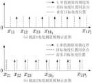
图1为本发明实施例中的“目标信号以及干扰信号为多普勒频移不敏感”信号的预处理原理图;Fig. 1 is the preprocessing principle diagram of "target signal and interference signal are Doppler frequency shift insensitive" signal in the embodiment of the present invention;
图2为本发明实施例中的目标信号以及干扰信号为“多普勒频移敏感”信号的预处理原理图;Fig. 2 is the preprocessing principle diagram that the target signal and the interference signal in the embodiment of the present invention are "Doppler frequency shift sensitive" signal;
图3为稀疏检测算法的矩阵相关系数μ(Φ)和高斯噪声矩阵的相关系数对比图;Figure 3 is a comparison diagram of the matrix correlation coefficient μ(Φ) of the sparse detection algorithm and the correlation coefficient of the Gaussian noise matrix;
其中,矩阵相关系数μ(Φ)为菱形标志点,高斯噪声矩阵的相关系数为空心箱和十字绘制的箱线图点;Among them, the matrix correlation coefficient μ(Φ) is the diamond mark point, and the correlation coefficient of the Gaussian noise matrix is the box plot point drawn by the hollow box and the cross;
图4为本发明实施例中的UDSA系统角度测量模糊性及其解模糊原理图;Fig. 4 is the UDSA system angle measurement ambiguity in the embodiment of the present invention and its de-ambiguity principle diagram;
图5为本发明实施例中的UDSA信号处理系统图;5 is a diagram of a UDSA signal processing system in an embodiment of the present invention;
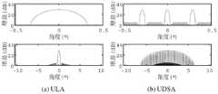
图6为ULA与UDSA的天线方向图;Fig. 6 is the antenna pattern of ULA and UDSA;
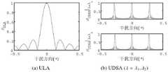
图7为ULA系统与UDSA系统目标与干扰导向矢量相关系数对比图;Figure 7 is a comparison diagram of the correlation coefficient between the target and the interference steering vector of the ULA system and the UDSA system;
图8为ULA与UDSA理论性能对比图;Figure 8 is a comparison chart of theoretical performance between ULA and UDSA;
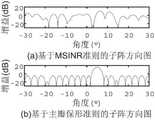
图9为不同旁瓣抑制方法的主瓣失真度图;Fig. 9 is the main lobe distortion degree diagram of different side lobe suppression methods;
图10为四种UDSA系统参数对稀疏检测算法进行仿真的仿真性能对比图;Figure 10 is a simulation performance comparison diagram of four UDSA system parameters for simulating the sparse detection algorithm;
图11为在不同SNR条件下,MSJNR、MESE及稀疏检测方法性能ROC曲线对比图;Figure 11 is a comparison chart of the performance ROC curves of MSJNR, MESE and sparse detection methods under different SNR conditions;
图12为角度坐标估计性能图。Figure 12 is a graph of the angle coordinate estimation performance.
具体实施方式Detailed ways
下面将参照附图更详细地描述本公开的示例性实施例。虽然附图中显示了本公开的示例性实施例,然而应当理解,可以以各种形式实现本公开而不应被这里阐述的实施例所限制。相反,提供这些实施例是为了能够更透彻地理解本公开,并且能够将本公开的范围完整的传达给本领域的技术人员。Exemplary embodiments of the present disclosure will be described in more detail below with reference to the accompanying drawings. While exemplary embodiments of the present disclosure are shown in the drawings, it should be understood that the present disclosure may be embodied in various forms and should not be limited by the embodiments set forth herein. Rather, these embodiments are provided so that the present disclosure will be more thoroughly understood, and will fully convey the scope of the present disclosure to those skilled in the art.
一种等距分布子阵列抗伴飞式干扰的方法,具体包括以下步骤:A method for equidistantly distributed sub-arrays to resist fly-by-flying interference, specifically comprising the following steps:
S1、将等距分布子阵列系统中各天线输入的目标回波及多个干扰信号进行时频域预处理滤至相同的窄带范围内,使得系统输入信号满足窄带条件,窄带范围内方向为θ的目标导向矢量可表示为:S1. Perform time-frequency domain preprocessing on the target echoes and multiple interference signals input by each antenna in the equidistantly distributed sub-array system to the same narrowband range, so that the system input signal satisfies the narrowband condition, and the direction in the narrowband range is θ. The goal-directed vector can be expressed as:

其中,


其中,θ为角度,λ为探测信号波长,d为阵元间距,L为阵列间距,M为子阵数量,N为子阵上的阵元数量;Among them, θ is the angle, λ is the wavelength of the detection signal, d is the array element spacing, L is the array spacing, M is the number of sub-arrays, and N is the number of array elements on the sub-array;
根据雷达探测信号的频带特性,可将目标回波及多个干扰信号划分为“多普勒频移不敏感”信号和“多普勒频移敏感”信号,下面分别对这两种信号的预处理方法分析:According to the frequency band characteristics of the radar detection signal, the target echo and multiple interfering signals can be divided into "Doppler shift insensitive" signals and "Doppler shift sensitive" signals. The preprocessing of these two signals is as follows. Method analysis:
当目标回波及多个干扰信号为“多普勒频移不敏感”信号时,时频域预处理流程如图1所示,具体包括以下步骤:When the target echo and multiple interfering signals are "Doppler frequency shift insensitive" signals, the time-frequency domain preprocessing process is shown in Figure 1, which includes the following steps:
为等距分布子阵列系统中的各天线接收机分别设置了一组相互毗邻、并覆盖全距离段的距离选通信号,每个距离选通信号宽度按照雷达距离分辨力设定,并为每个距离选通信号对应设置一个窄带滤波器,使各窄带滤波器工作在相同频点,当关注的目标速度未知时,该频点设置于零多普勒频移处,当速度已存在估计值时,频点设置于相应的多普勒频移处,各天线接收机接收到的多普勒频移不敏感的目标回波及多个干扰信号通过对应的距离选通信号以及窄带滤波器滤波至相同的窄带范围内,该信号处理方法在保证距离分辨力的同时,保证了系统窄带接收条件。同时,由于该信号样式对多普勒频移不敏感,保证了对不同多普勒频移的信号皆具备检测能力。For each antenna receiver in the equidistantly distributed sub-array system, a set of range gating signals adjacent to each other and covering the whole range are respectively set up. The width of each range gating signal is set according to the radar range resolution, and is set for each A narrowband filter is set corresponding to each range gating signal, so that each narrowband filter works at the same frequency point. When the speed of the target concerned is unknown, the frequency point is set at the zero Doppler frequency shift. When the speed has an estimated value When the frequency point is set at the corresponding Doppler frequency shift, the target echoes and multiple interference signals that are not sensitive to Doppler frequency shift received by each antenna receiver are filtered by the corresponding range gating signal and narrowband filter to Within the same narrowband range, the signal processing method ensures the narrowband receiving conditions of the system while ensuring the distance resolution. At the same time, since the signal pattern is not sensitive to Doppler frequency shift, it is guaranteed that the signal with different Doppler frequency shift has the detection ability.
当目标回波及多个干扰信号为“多普勒频移敏感”信号时,“PC+MTD”及“PD”体制雷达虽然频带覆盖范围(梳状频谱包络宽度)难以满足“窄带条件”,但其单根谱线是窄带的,因此,我们运用图2所示的信号处理架构提取单根谱线实现窄带化处理,时频域预处理具体包括以下步骤:When the target echo and multiple interfering signals are "Doppler shift sensitive" signals, although the "PC+MTD" and "PD" radars are difficult to meet the "narrowband conditions" in the frequency band coverage (comb spectrum envelope width), However, its single spectral line is narrowband. Therefore, we use the signal processing architecture shown in Figure 2 to extract a single spectral line to achieve narrowband processing. The time-frequency domain preprocessing specifically includes the following steps:
为等距分布子阵列系统中的各天线接收机分别设置了一组相互毗邻、并覆盖全距离段的距离选通信号,每个距离选通信号宽度按照雷达距离分辨力设定,以保证距离分辨力和作用距离全覆盖能力,并为每个距离选通信号对应设置一组滤波器组,滤波器组的频率覆盖范围与目标信号的无模糊测频范围相同,以保证对各种多普勒频移皆具备检测能力,各天线接收机接收到的多普勒频移敏感的目标回波及多个干扰信号通过对应的距离选通信号以及窄带滤波器滤波至相同的窄带范围内。For each antenna and receiver in the equidistantly distributed sub-array system, a set of distance gating signals adjacent to each other and covering the whole range are respectively set. The width of each range gating signal is set according to the radar range resolution to ensure the distance. Resolution and full coverage of the action distance, and set up a set of filter banks for each range gating signal, the frequency coverage of the filter bank is the same as the unambiguous frequency measurement range of the target signal, so as to ensure the accuracy of various Doppler signals. The Doppler shift-sensitive target echo and multiple interference signals received by each antenna receiver are filtered to the same narrowband range through the corresponding range gating signal and narrowband filter.
S2、为了降低旁瓣电平,对步骤S1经过预处理的目标回波及多个干扰信号进行空域滤波处理,具体为对等距分布子阵列系统中的空域滤波器作加窗处理,步骤S1经过预处理的目标回波及多个干扰信号通过加窗处理的空域滤波器进行空域滤波处理。接着将处理过的目标回波及多个干扰信号输入到等距分布子阵列系统中的各子阵中,如果运用自适应滤波器(如Capon滤波器)进行外部干扰抑制时,滤波器将在各干扰方向形成凹口,当外部存在主瓣干扰时,自适应滤波凹口将改变主瓣形状并导致目标增益下降,为了保持主瓣对目标的增益,各子阵运用相同的旁瓣干扰抑制滤波器对各子阵的旁瓣干扰进行抑制,抑制过程中对主瓣进行保形,各子阵滤除旁瓣干扰后,输出的目标回波及多个干扰信号可表示为:S2, in order to reduce the side lobe level, perform spatial filtering processing on the preprocessed target echo and multiple interference signals in step S1, specifically, performing windowing processing on the spatial filtering in the equidistant distribution sub-array system, step S1 goes through The preprocessed target echoes and a plurality of interference signals are subjected to spatial filtering processing through a windowed spatial filter. Then, input the processed target echo and multiple interference signals into each sub-array in the equidistantly distributed sub-array system. If an adaptive filter (such as Capon filter) is used to suppress external interference, the filter will be in each sub-array system. The interference direction forms a notch. When there is main lobe interference outside, the adaptive filtering notch will change the shape of the main lobe and cause the target gain to decrease. In order to maintain the gain of the main lobe to the target, each subarray uses the same side lobe interference suppression filter. The filter suppresses the side lobe interference of each sub-array, and preserves the shape of the main lobe during the suppression process. After each sub-array filters out the side lobe interference, the output target echo and multiple interference signals can be expressed as:

上述旁瓣干扰抑制滤波器通过无穷范数最小化的优化模型设计得到,所述优化模型以目标方向形成单位增益和副瓣干扰方向形成零增益为约束条件,以副瓣最高电平最小化为目标函数,其数学表达式如下所示:The above-mentioned side lobe interference suppression filter is obtained through the optimization model design of infinite norm minimization. The objective function whose mathematical expression is as follows:


其中,θc是期望的目标方向,Aj是副瓣干扰方向角度坐标集合,As是预设的副瓣方向角度采样集合,该优化模型在阵列结构和旁瓣干扰方向已估计的条件下,可通过凸优化方法得到全局最优解;Among them, θc is the desired target direction, Aj is the set of side lobe interference direction angle coordinates, As is the preset side lobe direction angle sampling set, the optimization model under the condition that the array structure and the side lobe interference direction have been estimated, can be obtained by The convex optimization method obtains the global optimal solution;
S3、经过研究发现,在伴飞式干扰背景下,等距分布子阵列系统系统中目标与主瓣干扰信号导向矢量呈现弱相关性,因此,zd信号目标与干扰具备稀疏特性,基于该特性,通过稀疏检测模型对子阵间的各步骤S2输出的目标回波及多个干扰信号实现目标信号检测,并运用如下优化方法对其进行求解:S3. After research, it is found that under the background of fly-by-flying interference, the target and the main lobe interference signal steering vector in the equidistantly distributed sub-array system show weak correlation. Therefore, the zd signal target and interference have sparse characteristics, based on this characteristic , through the sparse detection model, the target echo and multiple interference signals output by each step S2 between the sub-arrays are used to detect the target signal, and the following optimization method is used to solve it:

其中,Φ为传感矩阵,且Φ=[ad(sinθ0),ad(sinθ1),…,ad(sinθI-1)],导向矢量ad(sinθ)在sinθ域以λ/L为周期,为了避免传感矩阵列向量重复,此处在一个周期内取I个导向矢量,每个矢量对应的角度θi满足如下关系:Among them, Φ is the sensing matrix, and Φ=[ad (sinθ0 ), ad (sinθ1 ), ..., ad (sinθI-1 )], the steering vector ad( sinθ) is in the sinθ domain with λ /L is the period. In order to avoid the repetition of the column vector of the sensing matrix, I take one steering vector in one period, and the angle θi corresponding to each vector satisfies the following relationship:

其中,Φ为传感矩阵,且Φ=[ad(sinθ0),ad(sinθ1),…,ad(sinθI-1)],导向矢量ad(sinθ)在sinθ域以λL为周期,为了避免传感矩阵列向量重复,此处在一个周期内取I个导向矢量,每个矢量对应的角度θi满足如下关系:Among them, Φ is the sensing matrix, and Φ=[ad (sinθ0 ), ad (sinθ1 ), ..., ad( sinθI-1 )], the steering vector ad(sinθ) is in the sinθ domain with λL as Period, in order to avoid the repetition of the column vector of the sensing matrix, here I take one steering vector in one cycle, and the angle θi corresponding to each vector satisfies the following relationship:
θi=arcsinξi,θi = arcsinξi ,
ξi=ξ0+iΔ,0≤i≤I-1,ξi =ξ0 +iΔ, 0≤i≤I-1,

其中θ0是子阵波束中心指向,ξ0=sinθ0对应于波束中心指正的参考正弦值,各角度正弦值ξi构成等差数列,差值为Δ,其中I为角度采样数,λ为波长,此时无模糊测量区间范围为θ∈[θ0,θu),其中
对于稀疏检测模型,其可解性可由下式保证For the sparse detection model, its solvability can be guaranteed by the following equation

其中,k是可检测的信号数量,矩阵相关系数μ(Φ)表征矩阵Φ列向量之间的相关度;Among them, k is the number of detectable signals, and the matrix correlation coefficient μ(Φ) represents the correlation between the column vectors of the matrix Φ;
S4、当UDSA系统阵列间距L较大时,稀疏检测模型的无模糊测角区间将远小于子阵列主瓣宽度,因此,对于子阵列主瓣内角度为θx(θx满足sinθx=sinθr+qλL,0≤r<I,q∈Z)的目标回波信号,稀疏检测模型解算得出的角度将为θr,其中r为x关于I的余数:x≡r(modI).,S4. When the array spacing L of the UDSA system is large, the ambiguity-free angle measurement interval of the sparse detection model will be much smaller than the width of the main lobe of the sub-array. Therefore, for the main lobe of the sub-array, the inner angle is θx (θx satisfies sinθx=sinθr+qλL, For the target echo signal of 0≤r<I,q∈Z), the angle calculated by the sparse detection model will be θr, where r is the remainder of x with respect to I: x≡r(modI).,
因此,运用该检测算法对目标进行定位时,对于不同的q值,该稀疏检测算法将解出相同的余数r,该问题即角度测量模糊问题,为了消除角度测量模糊,通过FA技术在不同的载频上对步骤S3得到的同一个目标回波信号的角度θx进行多次测量并获取各自的余数,不同载频对应的余数集合之间的关系满足xk,p≡rk(modIk),其中k∈{1,2,···,K},p∈{1,2,···,Pk},对于不同的Ik,可获取相应的角度坐标余数并形成同余方程组如下所示:Therefore, when using the detection algorithm to locate the target, for different q values, the sparse detection algorithm will solve the same remainder r, which is the problem of angle measurement ambiguity. On the carrier frequency, the angle θx of the same target echo signal obtained in step S3 is measured multiple times and the respective remainders are obtained. The relationship between the remainder sets corresponding to different carrier frequencies satisfies xk,p ≡rk (modIk ) , where k∈{1,2,...,K}, p∈{1,2,...,Pk}, for different Ik , the corresponding angle coordinate remainders can be obtained and the congruence equations can be formed as follows shown:

其中,K代表FA过程中的不同载波数量,Ik为无模糊角度采样个数;而UDSA系统角度测量模糊性及其解模糊原理如图4所示,由该图可知各坐标集在真实目标对应的坐标位置处皆存在一个测量值。因此,在多载频系统单值测量范围内,真值点为各坐标集坐标的“凝聚点”,坐标集中的其余点为“发散点”,为了求取该凝聚点,此处选取坐标凝聚方差为目标函数;Among them, K represents the number of different carriers in the FA process, and Ik is the number of unambiguous angle samples; and the UDSA system angle measurement ambiguity and its defuzzification principle are shown in Figure 4. From this figure, it can be seen that each coordinate set is in the real target. There is a measurement value at the corresponding coordinate position. Therefore, in the single-value measurement range of the multi-carrier frequency system, the true value point is the "condensation point" of the coordinates of each coordinate set, and the other points in the coordinate set are the "diverging points". The variance is the objective function;
S5、基于模糊坐标聚类算法对步骤S4中的目标角度坐标xk,p进行处理,得到目标坐标均值,所述模糊坐标聚类算法对于目标角度坐标xk,p的处理方法具体如下:S5. The target angle coordinates xk,p in step S4 are processed based on the fuzzy coordinate clustering algorithm to obtain the mean value of the target coordinates. The processing method of the fuzzy coordinate clustering algorithm for the target angle coordinates xk,p is as follows:
S51、通过预置载频,使得步骤S4中各载频对应的模数Ik(k=1,2,···,K)互质,则无模糊角度测量范围扩展为
S52、在无模糊角度测量范围内,与任意余数rk对应的目标角度坐标分别为xk1,xk2,···,xkpk,其中,xkp=rk+(p-1)Ik;S52. In the measurement range of the unambiguous angle, the target angle coordinates corresponding to the arbitrary remainder rk are respectively xk1 , xk2 , ···, xkpk ,where xkp =rk +(p-1)Ik ;
S53、设置迭代次数初值n=0,并设置与各载频关联的目标角度初始位置分别为xk(n)=rk,k1,2,···,K,计算目标坐标聚类代价函数,其中,S53. Set the initial value of the number of iterations n=0, and set the initial position of the target angle associated with each carrier frequency to be xk (n)=rk , k1 , 2, ···, K, respectively, and calculate the target coordinate clustering cost function, where,

通过搜索该聚类代价函数最小值,可确定目标角度值。By searching for the minimum value of this clustering cost function, the target angle value can be determined.
如图5所示,本发明实施例还提供了一种等距分布子阵列的信号处理系统,由M个子阵组成,各阵列之间的距离为L,每个子阵列上有N个等距分布的全向天线阵元,其间距为d,系统的载波波长为λ,目标/干扰与信号处理系统之间的距离大于系统跨度。As shown in FIG. 5 , an embodiment of the present invention also provides a signal processing system for equidistantly distributed sub-arrays, which is composed of M sub-arrays, the distance between the arrays is L, and each sub-array has N equidistantly distributed sub-arrays The omnidirectional antenna array element of , its spacing is d, the carrier wavelength of the system is λ, and the distance between the target/interference and the signal processing system is greater than the system span.
当对本发明实施例提供的UDSA系统中的空域滤波器作加窗处理,加窗后主瓣宽度有所展宽,然而栅瓣间距不变。此处采用泰勒窗控制方向图旁瓣可得到如图6所示的UDSA天线系统与ULA天线系统方向图(按照表1设置天线参数)。When windowing is performed on the spatial filter in the UDSA system provided by the embodiment of the present invention, the width of the main lobe is broadened after the windowing, but the spacing of the grating lobes remains unchanged. Here, by using the Taylor window to control the side lobes of the pattern, the pattern of the UDSA antenna system and the ULA antenna system as shown in Figure 6 can be obtained (antenna parameters are set according to Table 1).
表1 ULA及UDSA阵列参数Table 1 ULA and UDSA array parameters

通过对比可知,天线阵元数量相等的条件下,UDSA系统比ULA系统可获得更窄的主瓣宽度。因此,UDSA系统可通过增加阵列间距提升目标与干扰的分辨能力(此处分辨能力提升无需增加天线单元,仅需增加阵列栅瓣数量)。By comparison, it can be seen that under the condition that the number of antenna elements is equal, the UDSA system can obtain a narrower main lobe width than the ULA system. Therefore, the UDSA system can improve the resolution between the target and the interference by increasing the array spacing (here, the resolution improvement does not need to increase the antenna element, but only needs to increase the number of array grating lobes).
为了分析本发明实施例提供的等距分布子阵列的信号处理系统(UDSA系统)能达到理论性能,对本发明实施例提供的系统与ULA系统在主瓣伴飞式干扰背景下的的最优滤波性能和空间谱估计性能下界(CRB)分别进行分析。In order to analyze that the signal processing system (UDSA system) of the equidistantly distributed sub-array provided by the embodiment of the present invention can achieve theoretical performance, the optimal filtering of the system provided by the embodiment of the present invention and the ULA system under the background of main lobe fly-by interference The performance and spatial spectral estimation performance lower bound (CRB) are analyzed separately.
由分析可知,阵列天线主瓣滤波性能主要取决于主瓣干扰与目标导向矢量的相关性。It can be seen from the analysis that the main lobe filtering performance of the array antenna mainly depends on the correlation between the main lobe interference and the target steering vector.
运用表1所示参数对ULA与UDSA两种系统的目标相关系数进行计算,其结果如图7所示。由该图可知,当干扰信号接近目标时,UDSA系统的导向矢量相关系数远小于ULA系统,因此UDSA系统在对抗伴飞式干扰过程中可获得更高的信噪比。然而,当干扰信号远离目标时,UDSA系统会在若干方向产生较大的相关峰,当干扰信号位于相关峰所在的角度时UDSA系统输出信干噪比将显著下降。Using the parameters shown in Table 1, the target correlation coefficients of the ULA and UDSA systems are calculated, and the results are shown in Figure 7. It can be seen from this figure that when the interference signal is close to the target, the correlation coefficient of the steering vector of the UDSA system is much smaller than that of the ULA system, so the UDSA system can obtain a higher signal-to-noise ratio in the process of combating the accompanying jammer. However, when the interfering signal is far away from the target, the UDSA system will generate large correlation peaks in several directions, and the output signal-to-interference-noise ratio of the UDSA system will decrease significantly when the interfering signal is located at the angle of the correlation peak.
通过对导向矢量相关系数表达式进行分析可知,该相关峰出现的位置与载波波长λ有关,因此本发明实施例中的实际UDSA系统设计时,通过运用一组不同的载波波长实施对空探测及空域滤波,从而有效避开相关峰值。By analyzing the expression of the correlation coefficient of the steering vector, it can be seen that the position of the correlation peak is related to the carrier wavelength λ. Therefore, when the actual UDSA system in the embodiment of the present invention is designed, a set of different carrier wavelengths are used to implement air detection and detection. Spatial filtering to effectively avoid correlation peaks.
图7(b)的上下两个子图分别示出了同一UDSA阵列在不同的载波波长条件下相关峰的位置。由该图可知,当载波波长变化时,相关峰位置亦将相应地发生变化,对于给定的一组载波,只要在其中一种载波波长作用下干扰与目标呈现弱相关性,系统即可得到较高的信干噪比,实现对目标的检测。The upper and lower subgraphs of Fig. 7(b) show the positions of the correlation peaks of the same UDSA array under different carrier wavelength conditions, respectively. It can be seen from this figure that when the carrier wavelength changes, the position of the correlation peak will also change accordingly. For a given set of carriers, as long as the interference and the target are weakly correlated under the action of one of the carrier wavelengths, the system can obtain High signal-to-interference-noise ratio to achieve target detection.
UDSA系统目标与干扰信号导向矢量的弱相关特性使其对抗主瓣伴飞式干扰成为可能。将表1所示参数计算得出UDSA系统及ULA系统输出信号的最大信干噪比及空间谱估计的CRB。图8示出了当目标方向固定时,两种系统的理论性能与干扰方向之间的关系曲线,由该图可知,UDSA系统在处理伴飞式干扰问题上具有更优的理论性能。The weak correlation between the UDSA target and the steering vector of the jamming signal makes it possible to counteract the main lobe fly-by jamming. The parameters shown in Table 1 are calculated to obtain the maximum signal-to-interference-to-noise ratio of the output signals of the UDSA system and the ULA system and the CRB of the spatial spectrum estimation. Figure 8 shows the relationship between the theoretical performance of the two systems and the interference direction when the target direction is fixed. From this figure, it can be seen that the UDSA system has better theoretical performance in dealing with the accompanying flight interference problem.
此外,我们还对本发明实施例经过步骤S2的旁瓣干扰抑制滤波器的处理效果与步骤S2不采用旁瓣干扰抑制滤波器处理而是采用MSJNR方法的干扰抑制处理的效果进行对比研究,两者干扰抑制方向图分别如图9(a)与图9(b)所示,该图表明基于本发明实施例步骤S2的优化模型的干扰抑制方法可有效保证天线主瓣不发生形变,且该方向图具有较低的副瓣电平,这些优点是MSJNR方法所不具备的。In addition, we also conduct a comparative study on the processing effect of the side lobe interference suppression filter in the embodiment of the present invention and the effect of the interference suppression processing using the MSJNR method instead of the side lobe interference suppression filter processing in step S2. The interference suppression patterns are shown in Fig. 9(a) and Fig. 9(b) respectively, which show that the interference suppression method based on the optimization model of step S2 in the embodiment of the present invention can effectively ensure that the main lobe of the antenna is not deformed, and the direction Figures have lower sidelobe levels, advantages that the MSJNR method does not have.
为了评估本发明实施例提供的方法和系统的工作性能,分别对方法和系统在主瓣干扰背景下的目标分辨性能、目标检测性能及角度估计性能进行仿真。UDSA系统天线配置参数及其对应的理论性能参数如表2所示。根据仿真需要,此处假设天线远场存在一个目标、两个主瓣积极干扰、两个旁瓣积极干扰,天线主瓣指向5°方向,目标角度坐标设置为3.2885°,干扰角度坐标分别设置为-18.3187°,3.2407°,3.3244°及15.1114°。该系统发射的雷达探测波形为简单脉冲,各干扰信号波形为相互独立的高斯白噪声。In order to evaluate the working performance of the method and system provided by the embodiments of the present invention, the target resolution performance, target detection performance and angle estimation performance of the method and system under the background of main lobe interference are simulated respectively. The UDSA system antenna configuration parameters and their corresponding theoretical performance parameters are shown in Table 2. According to the simulation needs, it is assumed here that there is one target, two main lobes and two active side lobes in the far field of the antenna, the main lobe of the antenna points to 5°, the target angle coordinates are set to 3.2885°, and the interference angle coordinates are respectively set to -18.3187°, 3.2407°, 3.3244° and 15.1114°. The radar detection waveforms emitted by the system are simple pulses, and the waveforms of each interference signal are independent Gaussian white noises.
表2系统参数设置Table 2 System parameter settings

UDSA系统阵列间距对分辨性能的影响Influence of Array Spacing of UDSA System on Resolution Performance
对于相同的目标与干扰环境,当天线阵列间距不同时,系统接收到的信号将表现出不同的稀疏性。此处设置目标回波的信噪比为SNR=20dB,干扰信号的干噪比为JNR=25dB,并分别按照表2所示的四种UDSA系统参数对稀疏检测算法进行仿真,可得到图10所示的检测结果,图10表明,通过增加UDSA系统子阵列之间的间距可有效提升系统对目标与主瓣干扰的分辨能力。For the same target and interference environment, when the antenna array spacing is different, the signals received by the system will show different sparsity. Here, the signal-to-noise ratio of the target echo is set to SNR=20dB, and the interference-to-noise ratio of the interference signal is JNR=25dB, and the sparse detection algorithm is simulated according to the four UDSA system parameters shown in Table 2. Figure 10 The detection results shown in Figure 10 show that by increasing the spacing between the sub-arrays of the UDSA system, the ability of the system to resolve the interference between the target and the main lobe can be effectively improved.
UDSA系统检测性能UDSA system detection performance
为了评估UDSA系统的目标检测性能,此处在表2所示的第IV组系统参数条件下,分别运用MSJNR,最大熵谱估计(maximum entropy spectrum estimation,MESE)和本文提出的方法对目标进行检测。系统在不同的信噪比条件下,运用上述检测方法分别做5000次Monte Carlo仿真,图11显示了接收机操作持性(receiver operating characteristic,ROC)曲线,该曲线展示了在不同SNR条件下的检测概率Pd与虚警概率Pf之间的关系。这些曲线表明我们提出的方法与MSJNR方法在低信噪比SNR=-8dB条件下皆具有较好的性能,而在SNR=-5dB,SNR=-2dB及SN=1dB时,我们提出的方法检测性能均优于其余方法。In order to evaluate the target detection performance of the UDSA system, under the conditions of the fourth group of system parameters shown in Table 2, MSJNR, maximum entropy spectrum estimation (MESE) and the method proposed in this paper are used to detect the target respectively. . The system performs 5000 Monte Carlo simulations using the above detection method under different signal-to-noise ratio conditions. Figure 11 shows the receiver operating characteristic (ROC) curve, which shows the performance under different SNR conditions. The relationship between the detection probability Pd and the false alarm probability Pf. These curves show that both our proposed method and the MSJNR method have better performance under the condition of low SNR=-8dB, while at SNR=-5dB, SNR=-2dB and SN=1dB, our proposed method detects The performance is better than the other methods.
UDSA系统角度估计性能UDSA system angle estimation performance
为了评估UDSA系统的角度估计性能,此处分别按照表2所示的第III组与第IV组系统参数设置阵列参数及载波波长,对角度估计性能进行仿真分析。在不同的信噪比条件下,运用角度坐标解模糊算法估计目标角度,图12(a)-(c)分别示出了角度估计算法的解模糊成功概率、误差均值与误差方差(含方差下界,即CRB)。由该图可知,基于坐标聚类的角度解模糊算法可在主瓣干扰背景下有效地解决角度测量模糊问题,其角度估计精度随着目标回波信噪比提升逐渐逼近该系统角度估计的CRB。In order to evaluate the angle estimation performance of the UDSA system, the array parameters and carrier wavelength are set according to the system parameters of Group III and Group IV shown in Table 2, respectively, and the simulation analysis of the angle estimation performance is carried out. Under different signal-to-noise ratio conditions, the angle coordinate defuzzification algorithm is used to estimate the target angle. Figure 12(a)-(c) shows the defuzzification success probability, error mean and error variance (including the lower bound of variance) of the angle estimation algorithm, respectively. , namely CRB). It can be seen from this figure that the angle deblurring algorithm based on coordinate clustering can effectively solve the problem of angle measurement ambiguity under the background of main lobe interference, and its angle estimation accuracy gradually approaches the CRB of the system angle estimation with the improvement of the target echo signal-to-noise ratio. .
综上所述,本发明实施例提供的等距分布子阵列抗伴飞式干扰的方法在天线单元数目固定的情形下,可通过增加系统子阵列间距有效提升系统分辨能力,该特性为对抗与目标邻近的伴飞式干扰提供了一种经济的解决方案;且在主瓣干扰场景下具有较高的目标与干扰分辨能力、目标检测能力及角度估计精度。To sum up, the method for anti-flying interference provided by the equidistantly distributed sub-array provided by the embodiment of the present invention can effectively improve the system resolution capability by increasing the system sub-array spacing when the number of antenna elements is fixed. The accompanying jammer near the target provides an economical solution; and in the main lobe jamming scenario, it has high target and jamming resolution capability, target detection capability and angle estimation accuracy.
尽管已经示出和描述了本发明的实施例,本领域的普通技术人员可以理解:在不脱离本发明的原理和宗旨的情况下可以对这些实施例进行多种变化、修改、替换和变型,本发明的范围由权利要求及其等同物限定。Although embodiments of the present invention have been shown and described, it will be understood by those of ordinary skill in the art that various changes, modifications, substitutions and alterations can be made in these embodiments without departing from the principles and spirit of the invention, The scope of the invention is defined by the claims and their equivalents.
Claims (7)


Priority Applications (1)
| Application Number | Priority Date | Filing Date | Title |
|---|---|---|---|
| CN202210225404.5ACN114740434B (en) | 2022-03-07 | 2022-03-07 | Equidistant distributed subarray system and method for resisting accompanying interference |
Applications Claiming Priority (1)
| Application Number | Priority Date | Filing Date | Title |
|---|---|---|---|
| CN202210225404.5ACN114740434B (en) | 2022-03-07 | 2022-03-07 | Equidistant distributed subarray system and method for resisting accompanying interference |
Publications (2)
| Publication Number | Publication Date |
|---|---|
| CN114740434Atrue CN114740434A (en) | 2022-07-12 |
| CN114740434B CN114740434B (en) | 2024-05-14 |
Family
ID=82275981
Family Applications (1)
| Application Number | Title | Priority Date | Filing Date |
|---|---|---|---|
| CN202210225404.5AActiveCN114740434B (en) | 2022-03-07 | 2022-03-07 | Equidistant distributed subarray system and method for resisting accompanying interference |
Country Status (1)
| Country | Link |
|---|---|
| CN (1) | CN114740434B (en) |
Cited By (1)
| Publication number | Priority date | Publication date | Assignee | Title |
|---|---|---|---|---|
| CN116148787A (en)* | 2023-04-20 | 2023-05-23 | 北京无线电测量研究所 | Phased array radar broadband directional diagram simulation method and device |
Citations (5)
| Publication number | Priority date | Publication date | Assignee | Title |
|---|---|---|---|---|
| CA2082781A1 (en)* | 1991-12-16 | 1993-06-17 | Gen Electric | Combining sidelobe canceller and mainlobe canceller for adaptive monopulse radar processing |
| CN106707253A (en)* | 2016-12-27 | 2017-05-24 | 南京长峰航天电子科技有限公司 | Networking radar and networking jammer countermeasure test device and method in test room |
| EP3690483A1 (en)* | 2019-02-04 | 2020-08-05 | Fraunhofer-Gesellschaft zur Förderung der angewandten Forschung e.V. | A method for synthesis of antenna array layouts or selection of waveform in a set of mutually incoherent apertures for radar and radio-frequency applications |
| CN113030939A (en)* | 2021-02-05 | 2021-06-25 | 中国人民解放军空军预警学院 | Sparse angle measurement method based on subarray space smoothing under main lobe interference |
| CN113050045A (en)* | 2021-02-09 | 2021-06-29 | 中国人民解放军空军研究院战略预警研究所 | Intelligent comprehensive main and side lobe interference resisting system and method |
- 2022
- 2022-03-07CNCN202210225404.5Apatent/CN114740434B/enactiveActive
Patent Citations (5)
| Publication number | Priority date | Publication date | Assignee | Title |
|---|---|---|---|---|
| CA2082781A1 (en)* | 1991-12-16 | 1993-06-17 | Gen Electric | Combining sidelobe canceller and mainlobe canceller for adaptive monopulse radar processing |
| CN106707253A (en)* | 2016-12-27 | 2017-05-24 | 南京长峰航天电子科技有限公司 | Networking radar and networking jammer countermeasure test device and method in test room |
| EP3690483A1 (en)* | 2019-02-04 | 2020-08-05 | Fraunhofer-Gesellschaft zur Förderung der angewandten Forschung e.V. | A method for synthesis of antenna array layouts or selection of waveform in a set of mutually incoherent apertures for radar and radio-frequency applications |
| CN113030939A (en)* | 2021-02-05 | 2021-06-25 | 中国人民解放军空军预警学院 | Sparse angle measurement method based on subarray space smoothing under main lobe interference |
| CN113050045A (en)* | 2021-02-09 | 2021-06-29 | 中国人民解放军空军研究院战略预警研究所 | Intelligent comprehensive main and side lobe interference resisting system and method |
Non-Patent Citations (1)
| Title |
|---|
| 周伟光;谭怀英;李归;康猛;: "双站对消抗主瓣干扰技术研究", 现代雷达, no. 07, 15 July 2018 (2018-07-15)* |
Cited By (2)
| Publication number | Priority date | Publication date | Assignee | Title |
|---|---|---|---|---|
| CN116148787A (en)* | 2023-04-20 | 2023-05-23 | 北京无线电测量研究所 | Phased array radar broadband directional diagram simulation method and device |
| CN116148787B (en)* | 2023-04-20 | 2023-06-23 | 北京无线电测量研究所 | Phased array radar broadband directional diagram simulation method and device |
Also Published As
| Publication number | Publication date |
|---|---|
| CN114740434B (en) | 2024-05-14 |
Similar Documents
| Publication | Publication Date | Title |
|---|---|---|
| CN103364764B (en) | Airborne radar non-stationary clutter suppression method | |
| CN110837074B (en) | Multi-common-frequency information source phase interferometer direction finding method based on digital beam forming | |
| CN106338713B (en) | A kind of vector array target port/starboard discrimination method based on wave beam null power | |
| Su et al. | Adaptive beamforming for nonstationary HF interference cancellation in skywave over-the-horizon radar | |
| CN105334508B (en) | A kind of grating lobe suppression method of thinned array broad-band EDFA | |
| CN108957419B (en) | Asynchronous interference suppression method based on notch filtering processing | |
| CN108872970B (en) | Grating lobe discrimination method suitable for general equidistant sparse array single-frequency signal beam forming | |
| CN108957406A (en) | A kind of radar main lobe interference suppression method neural network based | |
| CN113835068B (en) | A Blind Source Separation Real-Time Anti-mainlobe Interference Method Based on Independent Component Analysis | |
| CN114091328A (en) | Windowed two-dimensional deconvolution multi-beam power spectrum estimation algorithm | |
| CN113391286B (en) | Virtual aperture MIMO radar target detection method based on two-dimensional block sparse recovery | |
| CN114265058A (en) | MIMO radar target angle measurement method and device, electronic equipment and storage medium | |
| CN115656994B (en) | Real-time calibration method for bistatic active detection towing array shape | |
| CN111323750B (en) | A direct localization method based on acoustic vector array network | |
| CN114740434B (en) | Equidistant distributed subarray system and method for resisting accompanying interference | |
| Ma et al. | Spatiotemporal two-dimensional deconvolution beam imaging technology | |
| CN110764066B (en) | Target detection method based on real signal subspace in the presence of errors | |
| CN112327305A (en) | Rapid frequency domain broadband MVDR sonar wave beam forming method | |
| De et al. | Angle estimation using modified subarray level monopulse ratio algorithm and s-curve in digital phased array radar | |
| CN113406620B (en) | Distributed array angle measurement method for array decomposition | |
| CN113156392B (en) | Clutter suppression method based on pitching domain self-adaptive processing | |
| CN112415469B (en) | Rapid interference direction finding method for two-dimensional digital array radar | |
| Yin et al. | Range-angle two-dimensional anti jamming against dense false targets | |
| CN115166728B (en) | Space-based radar discrete sidelobe clutter identification method and system based on sliding window filtering loss | |
| Gong et al. | Study stap algorithm on interference target detect under nonhomogenous environment |
Legal Events
| Date | Code | Title | Description |
|---|---|---|---|
| PB01 | Publication | ||
| PB01 | Publication | ||
| SE01 | Entry into force of request for substantive examination | ||
| SE01 | Entry into force of request for substantive examination | ||
| GR01 | Patent grant | ||
| GR01 | Patent grant |