CN114733838B - An efficient cleaning device for medical nursing - Google Patents
An efficient cleaning device for medical nursingDownload PDFInfo
- Publication number
- CN114733838B CN114733838BCN202210659859.8ACN202210659859ACN114733838BCN 114733838 BCN114733838 BCN 114733838BCN 202210659859 ACN202210659859 ACN 202210659859ACN 114733838 BCN114733838 BCN 114733838B
- Authority
- CN
- China
- Prior art keywords
- tank
- tank body
- water
- pressure
- heating
- Prior art date
- Legal status (The legal status is an assumption and is not a legal conclusion. Google has not performed a legal analysis and makes no representation as to the accuracy of the status listed.)
- Expired - Fee Related
Links
- 238000004140cleaningMethods0.000titleclaimsabstractdescription40
- 230000000474nursing effectEffects0.000titleclaimsabstractdescription13
- 238000009835boilingMethods0.000claimsabstractdescription83
- 238000005192partitionMethods0.000claimsabstractdescription25
- 238000007789sealingMethods0.000claimsabstractdescription17
- XLYOFNOQVPJJNP-UHFFFAOYSA-NwaterSubstancesOXLYOFNOQVPJJNP-UHFFFAOYSA-N0.000claimsdescription75
- 238000010438heat treatmentMethods0.000claimsdescription57
- 238000004804windingMethods0.000claimsdescription20
- 238000004891communicationMethods0.000claimsdescription13
- 239000008236heating waterSubstances0.000claimsdescription4
- 238000005485electric heatingMethods0.000claimsdescription3
- 238000003825pressingMethods0.000claimsdescription3
- 230000001954sterilising effectEffects0.000abstractdescription3
- 238000000926separation methodMethods0.000abstract1
- 230000000694effectsEffects0.000description9
- 238000000034methodMethods0.000description9
- 238000010586diagramMethods0.000description8
- 230000008569processEffects0.000description8
- 238000004659sterilization and disinfectionMethods0.000description6
- 238000009834vaporizationMethods0.000description6
- 230000008016vaporizationEffects0.000description6
- 230000008859changeEffects0.000description4
- 230000007423decreaseEffects0.000description4
- 238000013021overheatingMethods0.000description4
- 239000007788liquidSubstances0.000description3
- 230000015572biosynthetic processEffects0.000description2
- 230000004048modificationEffects0.000description2
- 238000012986modificationMethods0.000description2
- 238000005273aerationMethods0.000description1
- 230000009172burstingEffects0.000description1
- 230000014509gene expressionEffects0.000description1
- 230000006872improvementEffects0.000description1
- 238000012546transferMethods0.000description1
Images


Classifications
- B—PERFORMING OPERATIONS; TRANSPORTING
- B08—CLEANING
- B08B—CLEANING IN GENERAL; PREVENTION OF FOULING IN GENERAL
- B08B3/00—Cleaning by methods involving the use or presence of liquid or steam
- B08B3/04—Cleaning involving contact with liquid
- B08B3/10—Cleaning involving contact with liquid with additional treatment of the liquid or of the object being cleaned, e.g. by heat, by electricity or by vibration
- A—HUMAN NECESSITIES
- A61—MEDICAL OR VETERINARY SCIENCE; HYGIENE
- A61L—METHODS OR APPARATUS FOR STERILISING MATERIALS OR OBJECTS IN GENERAL; DISINFECTION, STERILISATION OR DEODORISATION OF AIR; CHEMICAL ASPECTS OF BANDAGES, DRESSINGS, ABSORBENT PADS OR SURGICAL ARTICLES; MATERIALS FOR BANDAGES, DRESSINGS, ABSORBENT PADS OR SURGICAL ARTICLES
- A61L2/00—Methods or apparatus for disinfecting or sterilising materials or objects other than foodstuffs or contact lenses; Accessories therefor
- A61L2/02—Methods or apparatus for disinfecting or sterilising materials or objects other than foodstuffs or contact lenses; Accessories therefor using physical phenomena
- A61L2/04—Heat
- A61L2/06—Hot gas
- A61L2/07—Steam
- A—HUMAN NECESSITIES
- A61—MEDICAL OR VETERINARY SCIENCE; HYGIENE
- A61L—METHODS OR APPARATUS FOR STERILISING MATERIALS OR OBJECTS IN GENERAL; DISINFECTION, STERILISATION OR DEODORISATION OF AIR; CHEMICAL ASPECTS OF BANDAGES, DRESSINGS, ABSORBENT PADS OR SURGICAL ARTICLES; MATERIALS FOR BANDAGES, DRESSINGS, ABSORBENT PADS OR SURGICAL ARTICLES
- A61L2/00—Methods or apparatus for disinfecting or sterilising materials or objects other than foodstuffs or contact lenses; Accessories therefor
- A61L2/26—Accessories or devices or components used for biocidal treatment
- B—PERFORMING OPERATIONS; TRANSPORTING
- B08—CLEANING
- B08B—CLEANING IN GENERAL; PREVENTION OF FOULING IN GENERAL
- B08B13/00—Accessories or details of general applicability for machines or apparatus for cleaning
- B—PERFORMING OPERATIONS; TRANSPORTING
- B08—CLEANING
- B08B—CLEANING IN GENERAL; PREVENTION OF FOULING IN GENERAL
- B08B3/00—Cleaning by methods involving the use or presence of liquid or steam
- B08B3/04—Cleaning involving contact with liquid
- B08B3/10—Cleaning involving contact with liquid with additional treatment of the liquid or of the object being cleaned, e.g. by heat, by electricity or by vibration
- B08B3/106—Cleaning involving contact with liquid with additional treatment of the liquid or of the object being cleaned, e.g. by heat, by electricity or by vibration by boiling the liquid
- A—HUMAN NECESSITIES
- A61—MEDICAL OR VETERINARY SCIENCE; HYGIENE
- A61L—METHODS OR APPARATUS FOR STERILISING MATERIALS OR OBJECTS IN GENERAL; DISINFECTION, STERILISATION OR DEODORISATION OF AIR; CHEMICAL ASPECTS OF BANDAGES, DRESSINGS, ABSORBENT PADS OR SURGICAL ARTICLES; MATERIALS FOR BANDAGES, DRESSINGS, ABSORBENT PADS OR SURGICAL ARTICLES
- A61L2202/00—Aspects relating to methods or apparatus for disinfecting or sterilising materials or objects
- A61L2202/10—Apparatus features
- A61L2202/11—Apparatus for generating biocidal substances, e.g. vaporisers, UV lamps
- A—HUMAN NECESSITIES
- A61—MEDICAL OR VETERINARY SCIENCE; HYGIENE
- A61L—METHODS OR APPARATUS FOR STERILISING MATERIALS OR OBJECTS IN GENERAL; DISINFECTION, STERILISATION OR DEODORISATION OF AIR; CHEMICAL ASPECTS OF BANDAGES, DRESSINGS, ABSORBENT PADS OR SURGICAL ARTICLES; MATERIALS FOR BANDAGES, DRESSINGS, ABSORBENT PADS OR SURGICAL ARTICLES
- A61L2202/00—Aspects relating to methods or apparatus for disinfecting or sterilising materials or objects
- A61L2202/10—Apparatus features
- A61L2202/17—Combination with washing or cleaning means
- A—HUMAN NECESSITIES
- A61—MEDICAL OR VETERINARY SCIENCE; HYGIENE
- A61L—METHODS OR APPARATUS FOR STERILISING MATERIALS OR OBJECTS IN GENERAL; DISINFECTION, STERILISATION OR DEODORISATION OF AIR; CHEMICAL ASPECTS OF BANDAGES, DRESSINGS, ABSORBENT PADS OR SURGICAL ARTICLES; MATERIALS FOR BANDAGES, DRESSINGS, ABSORBENT PADS OR SURGICAL ARTICLES
- A61L2202/00—Aspects relating to methods or apparatus for disinfecting or sterilising materials or objects
- A61L2202/20—Targets to be treated
- A61L2202/24—Medical instruments, e.g. endoscopes, catheters, sharps
Landscapes
- Health & Medical Sciences (AREA)
- Epidemiology (AREA)
- Life Sciences & Earth Sciences (AREA)
- Animal Behavior & Ethology (AREA)
- General Health & Medical Sciences (AREA)
- Public Health (AREA)
- Veterinary Medicine (AREA)
- Cleaning By Liquid Or Steam (AREA)
Abstract
Description
Translated fromChinese技术领域technical field
本发明涉及一种医疗器械的清洗设备,尤其涉及内科护理用高效清洁装置。The invention relates to a cleaning device for medical instruments, in particular to a high-efficiency cleaning device for medical nursing.
背景技术Background technique
内科护理器械的清洗,并不向外科手术器械,直接用于人体组织。对于清洗消毒的过程非常严格。主要是些常用的多次使用的护理器械。现有技术中有多种清洗这类器械的装置,但结构均非常复杂,联动部件多,使用和后续维护都非常麻烦,并不适用于医护自行操作,如中国专利CN112371616B。The cleaning of medical nursing instruments is not used for surgical instruments, but is directly used for human tissue. The cleaning and disinfection process is very strict. Mainly some commonly used multiple-use nursing equipment. There are various devices for cleaning such instruments in the prior art, but they are all very complicated in structure, have many linkage parts, and are very troublesome to use and maintain.
现有技术中,CN109092759B 负压清洗机,利用负压沸腾,提高气体发生量,并对沸煮液体充气的操作,利用气泡来破裂产生的压力和局部高温达到清洁器械的目的。但其设备存在几个弊端。负压下,水的汽化温度降低,气体量相比正压沸煮更大,要维持负压需要不断的抽吸沸煮设备内的气体,如果气泵的功率是恒定的,加热设备的放热功率也恒定,但水的量会随着汽化过程快速减少,水量越少,加热设备功率不变的情况下向水中传导的热量越高,汽化速率越快,就使得设备中气体排不出去,气压升高,汽化速率减慢,气泡量减少。但如果要调整气泵功率、加热效率、水量,来控制汽化速率保持恒定,这对设备的精密程度要求过高,设备构造复杂,不适于小型化,也不适用于科室内的医护人员自行操作使用。In the prior art, the CN109092759B negative pressure cleaning machine utilizes negative pressure boiling to increase the amount of gas generated, and the operation of inflating the boiling liquid uses the pressure and local high temperature generated by the bubble to burst to achieve the purpose of cleaning the equipment. But its device has several drawbacks. Under negative pressure, the vaporization temperature of water decreases, and the amount of gas is larger than that of positive pressure boiling. To maintain the negative pressure, it is necessary to continuously pump the gas in the boiling equipment. If the power of the air pump is constant, the heating equipment will release heat. The power is also constant, but the amount of water will decrease rapidly with the vaporization process. The less the amount of water, the higher the heat conduction to the water when the power of the heating equipment remains unchanged, and the faster the vaporization rate, so that the gas in the equipment cannot be discharged. The air pressure increases, the rate of vaporization slows, and the amount of air bubbles decreases. However, if you want to adjust the power of the air pump, the heating efficiency, and the amount of water to keep the vaporization rate constant, this requires too much precision of the equipment, and the equipment is complicated in structure, which is not suitable for miniaturization, nor is it suitable for medical staff in the department to operate and use by themselves. .
发明内容SUMMARY OF THE INVENTION
本申请实施例通过提供一种内科护理用高效清洁装置,能够以简洁的结构,实现相比现有技术更有的清洁和效果效果。The embodiments of the present application provide a high-efficiency cleaning device for medical nursing, which can achieve more cleaning and better effects than the prior art with a simple structure.
本申请实施例提供了一种内科护理用高效清洁装置,包括沸煮罐,沸煮罐用于容纳器械并对水进行加热,The embodiment of the present application provides a high-efficiency cleaning device for medical care, including a boiling tank, which is used for accommodating instruments and heating water,
还包括压力罐,压力罐用于容纳沸煮罐,并对沸煮罐施加压力;Also includes a pressure tank, which is used to accommodate and apply pressure to the boiling tank;
所述压力罐包括罐体、密封盖、附加管;The pressure tank includes a tank body, a sealing cover and an additional pipe;
所述罐体顶端开口与密封盖可拆卸密封固定连接;所述密封盖上固定一个单向压力阀,单向压力阀用于罐体向环境排气;The top opening of the tank body is detachably sealed and fixedly connected with the sealing cover; a one-way pressure valve is fixed on the sealing cover, and the one-way pressure valve is used for exhausting the tank body to the environment;
所述罐体内固定一个分隔板,分隔板将罐体分成上下两个腔体,下侧腔体的空间容积是上侧腔体空间容积的0.5-3倍;分隔板上带有连通上下两个腔体的通孔;所述沸煮罐固定在分隔板的上侧;A partition plate is fixed in the tank body, the partition plate divides the tank body into two upper and lower cavities, the space volume of the lower side cavity is 0.5-3 times the space volume of the upper side cavity; The through holes of the upper and lower chambers; the boiling pot is fixed on the upper side of the partition plate;
所述罐体下侧腔体带有一个连通管,通过连通管与环境连通;The cavity on the lower side of the tank body is provided with a communication pipe, which is communicated with the environment through the communication pipe;
所述附加管固定在罐体的一侧,且与罐体的下侧腔体连通;所述附加管内设置伸缩部,伸缩部用于带动活塞板在分隔板下侧的腔体上下移动;The additional pipe is fixed on one side of the tank body and communicates with the lower cavity of the tank body; a telescopic part is arranged in the additional pipe, and the telescopic part is used to drive the piston plate to move up and down in the cavity on the lower side of the partition plate;
所述活塞板与罐体下侧滑动密封配合;活塞板下移能够使分隔板上侧腔体气压降低;The piston plate is slidingly and sealedly matched with the lower side of the tank body; the downward movement of the piston plate can reduce the air pressure of the cavity on the upper side of the partition plate;
所述沸煮罐的底部固定加热部,加热部用于加热沸煮罐内的清洗用水;常压下加热部能够将水加热到100℃,气压大于一个标准大气压时,加热部能够将水加热至120℃。A heating part is fixed on the bottom of the boiling pot, and the heating part is used to heat the cleaning water in the boiling pot; the heating part can heat the water to 100°C under normal pressure, and when the air pressure is higher than a standard atmospheric pressure, the heating part can heat the water to 120°C.
进一步的,还包括水罐,水罐固定在罐体内;水罐通过双向压力阀与沸煮罐连通;所述水罐带有第二伸缩部,第二伸缩部用于将水罐中的水压入沸煮罐内,也能够将沸煮罐内的水抽入水罐中。Further, it also includes a water tank, which is fixed in the tank body; the water tank is communicated with the boiling tank through a two-way pressure valve; the water tank has a second telescopic part, and the second telescopic part is used for the water in the water tank It can also be pressed into the boiling pot, and the water in the boiling pot can also be pumped into the water tank.
进一步的,所述沸煮罐内固定有筛板用于限制器械的纵向最低位置,所述水罐在筛板的下侧与沸煮罐连通。Further, a sieve plate is fixed in the boiling pot to limit the lowest longitudinal position of the instrument, and the water tank is communicated with the boiling pot on the lower side of the sieve plate.
进一步的,所述水罐为环形,环绕在沸煮罐的外侧。Further, the water tank is annular and surrounds the outside of the boiling tank.
进一步的,所述水罐底部为硬质环,固定在沸煮罐上,硬质环上固定环形的弹性囊,所述第二伸缩部用于压缩和拉伸弹性囊。Further, the bottom of the water tank is a hard ring, which is fixed on the boiling pot, an annular elastic bag is fixed on the hard ring, and the second telescopic part is used for compressing and stretching the elastic bag.
进一步的,还包括第二加热组件,第二加热组件包括加热环和第三伸缩组件;Further, it also includes a second heating assembly, and the second heating assembly includes a heating ring and a third telescopic assembly;
所述加热环包括环体,环体为电力加热环,其与沸煮罐内壁或外壁滑动配合;The heating ring includes a ring body, and the ring body is an electric heating ring, which is slidingly matched with the inner wall or the outer wall of the boiling pot;
所述第三伸缩组件用于带动环体在沸煮罐纵向上移动。The third telescopic assembly is used to drive the ring body to move in the longitudinal direction of the boiling pot.
进一步的,所述环体位于沸煮罐内,环体外环面与沸煮罐内壁滑动配合;Further, the ring body is located in the boiling pot, and the outer ring surface of the ring body is slidingly matched with the inner wall of the boiling pot;
所述加热环还包括连接管和软管;The heating ring further includes a connecting pipe and a hose;
所述连接管为硬质管,其一端与加热环上的环形管道固定连通,空余端位于环体中心处;The connecting pipe is a rigid pipe, one end of which is fixedly connected with the annular pipe on the heating ring, and the spare end is located at the center of the ring body;
所述软管一端与加热环上的环形管道连通,另一端指向加热环内,软管有多个;软管为橡胶管,其表面上侧带有沿长度方向均匀间隔分布的通孔,通孔在内部充气时打开,内部无压力作用下封闭;One end of the hose is communicated with the annular pipe on the heating ring, and the other end points into the heating ring. There are multiple hoses; The hole is opened when inflated inside, and closed without pressure inside;
所述第三伸缩部包括牵拉管和卷绕辊;the third telescopic part includes a pulling tube and a winding roller;
所述牵拉管与连接管的空余端固定连通;牵拉管上带有弹性囊,弹性囊受压能够通过牵拉管向软管充气;The pulling tube is in fixed communication with the free end of the connecting tube; the pulling tube is provided with an elastic bag, and the elastic bag can be inflated to the hose through the pulling tube under pressure;
所述卷绕辊由电机传动,定位在罐体的上部;卷绕辊用于卷绕牵拉管;还包括一个从动辊,从动辊定位在沸煮罐的正上方,所述牵拉管绕过从动辊卷绕在卷绕辊上,使卷绕辊卷绕牵拉管时,能够带动环体上移。The winding roller is driven by the motor and is positioned on the upper part of the tank body; the winding roller is used for winding the pulling tube; it also includes a driven roller, which is positioned just above the boiling pot, and the pulling The tube bypasses the driven roller and is wound on the winding roller, so that when the winding roller winds and draws the tube, it can drive the ring body to move up.
进一步的,所述软管有4个,在环体内轴向均匀间隔分布,软管的长度不小于环体的半径。Further, there are four said hoses, which are evenly distributed in the axial direction of the ring body, and the length of the hoses is not less than the radius of the ring body.
本申请实施例中提供的一个或多个技术方案,至少具有如下技术效果或优点:One or more technical solutions provided in the embodiments of this application have at least the following technical effects or advantages:
通过将调整压力的压力罐和沸煮罐分开,沸煮罐设置在压力罐内,利用机械方式进行抽吸形成负压,在沸水内形成大量气泡。当蒸汽增多后,活塞板回移,压力罐内形成正压,使水沸腾温度升高,进行高温消毒,然后再次抽吸形成负压,在水温处于过热超过常压沸腾温度而未汽化快速转变到压力低于常压时,会更快速的汽化,短时间内形成相比于更多的气泡。重复上述的正压和负压交替的过程,能够在设备结构简单,便于操作的情况下,相比于现有技术中始终维持稳定负压状态的沸煮操作,能够在正压过热转负压态形成更多的气泡冲击,且正压过热能够有效的效果,形成更加的清洁消毒效果。By separating the pressure-adjusting pressure tank and the boiling tank, the boiling tank is set in the pressure tank, and suction is performed mechanically to form a negative pressure, and a large number of air bubbles are formed in the boiling water. When the steam increases, the piston plate moves back, and a positive pressure is formed in the pressure tank, which increases the boiling temperature of the water, conducts high-temperature sterilization, and then sucks again to form a negative pressure. When the pressure is lower than normal pressure, it will vaporize more rapidly, and more bubbles will be formed in a short time. Repeating the above-mentioned alternating process of positive pressure and negative pressure, under the condition that the device structure is simple and easy to operate, compared with the boiling operation that always maintains a stable negative pressure state in the prior art, it is possible to change the negative pressure from positive pressure overheating to negative pressure. The state forms more bubble impact, and the positive pressure overheating can effectively effect, forming a more cleaning and disinfection effect.
附图说明Description of drawings
图1 为清洁装置的主视结构示意图;Figure 1 is a schematic diagram of the front view of the cleaning device;
图2 为清洁装置的俯视示意图;Figure 2 is a schematic top view of the cleaning device;
图3 为带有水罐的清洁装置结构示意图;Figure 3 is a schematic structural diagram of a cleaning device with a water tank;
图4 为水罐受压时的工作状态示意图;Figure 4 is a schematic diagram of the working state of the water tank when it is under pressure;
图5 为带有加热环的装置结构示意图;Figure 5 is a schematic diagram of the device structure with a heating ring;
图6 为加热环位于沸煮罐内时的结构示意图;Fig. 6 is the structural schematic diagram when the heating ring is located in the boiling pot;
图7 为牵拉管结构示意图;Figure 7 is a schematic diagram of the structure of the pulling tube;
图8 为加热环结构示意图;Figure 8 is a schematic diagram of the structure of the heating ring;
图9 为加热环与器械配合时气泡发生状态示意图;Figure 9 is a schematic diagram of the state of bubble generation when the heating ring is matched with the instrument;
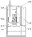
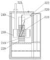
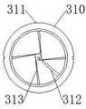
图中:压力罐100、罐体110、分隔板111、通槽112、连通管113、密封盖120、单向压力阀121、附加管130、伸缩部131、活塞板132;In the figure:
沸煮罐200、筛板210、加热部220、水罐230、第二伸缩部240;
第二加热组件300、加热环310、环体311、连接管312、软管313、第三伸缩部320、牵拉管321、弹性囊3211、卷绕辊322。The
具体实施方式Detailed ways
为了便于理解本发明,下面将参照相关附图对本申请进行更全面的描述;附图中给出了本发明的较佳实施方式,但是,本发明可以以许多不同的形式来实现,并不限于本文所描述的实施方式;相反地,提供这些实施方式的目的是使对本发明的公开内容理解的更加透彻全面。In order to facilitate the understanding of the present invention, the present application will be described more fully below with reference to the related drawings; the preferred embodiments of the present invention are given in the drawings, however, the present invention can be implemented in many different forms, and is not limited to Embodiments are described herein; rather, these embodiments are provided so that a thorough and complete understanding of the present disclosure will be provided.
需要说明的是,本文所使用的术语“垂直”、“水平”、“上”、“下”、“左”、“右”以及类似的表述只是为了说明的目的,并不表示是唯一的实施方式。It should be noted that the terms "vertical", "horizontal", "upper", "lower", "left", "right" and similar expressions used herein are for illustrative purposes only and do not represent the only implementation Way.
除非另有定义,本文所使用的所有的技术和科学术语与属于本发明的技术领域的技术人员通常理解的含义相同;本文中在本发明的说明书中所使用的术语只是为了描述具体的实施方式的目的,不是旨在于限制本发明;本文所使用的术语“和/或”包括一个或多个相关的所列项目的任意的和所有的组合。Unless otherwise defined, all technical and scientific terms used herein have the same meaning as commonly understood by one of ordinary skill in the technical field of the present invention; the terms used herein in the description of the present invention are only used to describe specific embodiments is not intended to limit the invention; as used herein, the term "and/or" includes any and all combinations of one or more of the associated listed items.
通过将调整压力的压力罐和沸煮罐分开,沸煮罐设置在压力罐内,利用机械方式进行抽吸形成负压,在沸水内形成大量气泡。当蒸汽增多后,活塞板回移,压力罐内形成正压,使水沸腾温度升高,进行高温消毒,然后再次抽吸形成负压,在水温处于过热超过常压沸腾温度而未汽化快速转变到压力低于常压时,会更快速的汽化,短时间内形成相比于更多的气泡。重复上述的正压和负压交替的过程,能够在设备结构简单,便于操作的情况下,相比于现有技术中始终维持稳定负压状态的沸煮操作,能够在正压过热转负压态形成更多的气泡冲击,且正压过热能够有效的效果,形成更加的清洁消毒效果。如图1所示。By separating the pressure-adjusting pressure tank and the boiling tank, the boiling tank is set in the pressure tank, and suction is performed mechanically to form a negative pressure, and a large number of air bubbles are formed in the boiling water. When the steam increases, the piston plate moves back, and a positive pressure is formed in the pressure tank, which increases the boiling temperature of the water, conducts high-temperature sterilization, and then sucks again to form a negative pressure. When the pressure is lower than normal pressure, it will vaporize more rapidly, and more bubbles will be formed in a short time. Repeating the above-mentioned alternating process of positive pressure and negative pressure, under the condition that the device structure is simple and easy to operate, compared with the boiling operation that always maintains a stable negative pressure state in the prior art, it is possible to change the negative pressure from positive pressure overheating to negative pressure. The state forms more bubble impact, and the positive pressure overheating can effectively effect, forming a more cleaning and disinfection effect. As shown in Figure 1.
实施例一Example 1
如图1-2所示,一种内科护理用高效清洁装置,包括沸煮罐200,沸煮罐200用于容纳器械并对水进行加热,As shown in Figs. 1-2, a high-efficiency cleaning device for medical nursing includes a boiling
还包括压力罐100,压力罐100用于容纳沸煮罐200,并对沸煮罐200施加压力;Also includes a
所述压力罐100包括罐体110、密封盖120、附加管130;The
所述罐体110顶端开口与密封盖120可拆卸密封固定连接;所述密封盖120上固定一个单向压力阀121,单向压力阀121用于罐体110向环境排气;The top opening of the
所述罐体110内固定一个分隔板111,分隔板111将罐体110分成上下两个腔体,下侧腔体的空间容积是上侧腔体空间容积的0.5-3倍;分隔板111上带有连通上下两个腔体的通孔;所述沸煮罐200固定在分隔板111的上侧;A
所述罐体110下侧腔体带有一个连通管113,通过连通管113与环境连通;The cavity on the lower side of the
所述附加管130固定在罐体110的一侧,且与罐体110的下侧腔体连通;所述附加管130内设置伸缩部131,伸缩部131用于带动活塞板132在分隔板111下侧的腔体上下移动;The
所述活塞板132与罐体110下侧滑动密封配合;活塞板132下移能够使分隔板111上侧腔体气压降低;The
所述沸煮罐200的底部固定加热部220,加热部220用于加热沸煮罐200内的清洗用水;常压下加热部220能够将水加热到100℃,气压大于一个标准大气压时,加热部220能够将水加热至120℃。A
实际的器械清洁过程如下:The actual instrument cleaning process is as follows:
步骤一、将器械放入沸煮罐200,打开加热部220,对水进行加热;Step 1. Put the device into the boiling
步骤二、测量水温,在70-80℃时,盖上密封盖120,开启伸缩部131伸缩部可以使用电动伸缩筒、螺杆螺套配合的结构、气缸或是油缸均可,伸缩部131带动活塞板132下移,使分隔板111上侧的气压下降,沸煮罐200内水快速沸腾;Step 2: Measure the water temperature. When the temperature is 70-80°C, cover the sealing
步骤三、保持活塞板132的位置不动,维持1-5分钟,再提升活塞板132使分隔板111上侧增压水蒸气会逐渐增大腔体内的压力,分隔板111上移能够瞬时增大腔体压力,压力由单向压力阀121控制,单向压力阀的连通压力可以设置在1.05-1.2个大气压,维持该压力3-5分钟;Step 3: Keep the position of the
步骤四、下移活塞板132使分隔板111上侧压力瞬时下降,待单向压力阀121排气时再提升活塞板132;分隔板111的下侧空间可以在横向上拓展,如图2所示,一个大型的箱体作为分隔板111下侧的空间,Step 4: Move the
步骤五、重复步骤四2-10次,然后关闭加热部220,待水冷却后,打开密封盖120,取出器械。Step 5: Repeat step 4 for 2-10 times, then turn off the
上述过程,能够通过机械结构实现沸煮罐200内的水,反复处于大于常压和低于常压这两个状态,这样水就在大于常压的过热消毒状态105-120℃,转道低于常压时的瞬时大量沸腾气泡冲击清洗器械的状态。反复多次后,清洁效果,相比维持在某一负压状态,低温沸腾加充气清洗的效果要更佳。The above process can realize that the water in the boiling
实施例二Embodiment 2
器械的清洗,通常都是直接注满水,使水能够没过器械,但是,气泡的形成和破裂的位置是基本固定的。在热源处形成小气泡,随后变大后脱离热源,上移膨胀,到水压降低处破裂。现有技术使用的多个加热肋条,增加热源面积,使气泡在多个位置形成,但仍然不能改变气泡的破裂的位置。这对于长条状的器械清洗并不能完全。尤其是小型器械,不能大量平铺器械,只能竖向放置器械,问题就更突出。因此,对沸煮罐200做进一步的改良。如图3-4所示。The cleaning of instruments is usually directly filled with water so that the water can cover the instruments, but the positions of bubble formation and rupture are basically fixed. Small bubbles are formed at the heat source, and then become larger and separate from the heat source, move up and expand, and burst when the water pressure decreases. The multiple heating ribs used in the prior art increase the area of the heat source, so that the bubbles are formed in multiple positions, but still cannot change the position where the bubbles burst. This is not complete for long instrument cleaning. Especially for small instruments, a large number of instruments cannot be laid flat, and the instruments can only be placed vertically, and the problem is even more prominent. Therefore, the boiling
还包括水罐230,水罐230固定在罐体110内;水罐230通过双向压力阀与沸煮罐200连通;所述水罐230带有第二伸缩部240,第二伸缩部240用于将水罐230中的水压入沸煮罐200内,也能够将沸煮罐200内的水抽入水罐230中。It also includes a
在完成实施例一的步骤中,通过控制第二伸缩部240向沸煮罐200内加水,使水位从筛板210上侧逐级上涨,可以分2-5级完成。每加一级水完成实施例一种的步骤1-5,使气泡在上移过程中接近液面处破裂的位置对应器械不同的位置。从而对长度较大的器械进行全方位的气泡冲击清洗。当然,也可以先把沸煮罐内的水注满,再抽吸到水罐里,形成水位逐级下降的过程,完成清洗和沸煮。In the steps of completing the first embodiment, the water level is gradually increased from the upper side of the
第二伸缩部240可以是电动伸缩筒、油缸、螺杆螺母座等常用方式。The second
所述沸煮罐200内固定有筛板210用于限制器械的纵向最低位置,所述水罐230在筛板210的下侧与沸煮罐连通。A
一方面,这样能够避免水罐230直接接触加热部220,避免内部水温过高汽化,另一方面,能够从下至上逐级加水,避免飞溅。此外,水罐230逐级加水至水量淹没器械,还能够起到补水的作用。On the one hand, this can prevent the
所述水罐230为环形,环绕在沸煮罐200的外侧。The
所述水罐230底部为硬质环,固定在沸煮罐200上,硬质环上固定环形的弹性囊,所述第二伸缩部240用于压缩和拉伸弹性囊。The bottom of the
实施例三Embodiment 3
固定位置的加热,气泡的发生位置是确定的,虽然能够改变液位,来改变气泡破裂的位置但,气泡的发生位置如果也可以改变,则能够更精确的针对器械的某一纵向区域进行精准的气泡冲击清洗,并能够增大气泡的针对该区域的形成量。如图5-6所示。Heating at a fixed location, the location of the bubbles is determined, although the liquid level can be changed to change the location of the bubbles bursting, but if the location of the bubbles can also be changed, it can be more accurate for a certain longitudinal area of the instrument. The bubble impact cleaning, and can increase the formation of bubbles for this area. As shown in Figure 5-6.
还包括第二加热组件300,第二加热组件300包括加热环310和第三伸缩组件320;Also includes a
所述加热环310包括环体311,环体311为电力加热环,其与沸煮罐200内壁或外壁滑动配合;The
所述第三伸缩组件320用于带动环体311在沸煮罐200纵向上移动。The third
实际使用时,可以是在沸煮罐200内注满水后,然后逐级提升加热环,使沸煮罐200纵向上,逐级的受到额外的加热。在加热环310处增加气泡发生量,提高该区域以及该区域以上部分的气泡冲击效果。In actual use, after the boiling
为了能够直接在临近器械的区域,或是器械表面形成气泡,对加热环作进一步的改良。如图6-9所示。In order to be able to form bubbles directly in the area adjacent to the instrument, or on the surface of the instrument, the heating ring is further modified. As shown in Figure 6-9.
所述环体311位于沸煮罐200内,环体311外环面与沸煮罐200内壁滑动配合;The
所述加热环310还包括连接管312和软管313;The
所述连接管312为硬质管,其一端与加热环310上的环形管道固定连通,空余端位于环体311中心处;The connecting
所述软管313一端与加热环310上的环形管道连通,另一端指向加热环310内,软管313有多个;软管313为橡胶管,其表面上侧带有沿长度方向均匀间隔分布的通孔,通孔在内部充气时打开,内部无压力作用下封闭;One end of the
所述第三伸缩部320包括牵拉管321和卷绕辊322;The third
所述牵拉管321与连接管312的空余端固定连通;牵拉管321上带有弹性囊3211,弹性囊3211受压能够通过牵拉管321向软管313充气;The pulling
所述卷绕辊322由电机传动,定位在罐体110的上部;卷绕辊322用于卷绕牵拉管321;还包括一个从动辊,从动辊定位在沸煮罐200的正上方,所述牵拉管321绕过从动辊卷绕在卷绕辊322上,使卷绕辊322卷绕牵拉管321时,能够带动环体311上移。The winding
使用时,从沸煮罐200的筛板210开始,逐级提升环体311,卷绕过程中会挤压弹性囊3211,使软管313表面形成微小的气泡,气泡临近或是直接贴在器械上,如图9所示。配合加热操作,这些微小气泡会快速膨胀,部分上移后破裂,部分在附近区域破裂,达到对环体311附近区域进行气泡冲击清洗的目的。When in use, starting from the
所述软管313有4个,在环体311内轴向均匀间隔分布,软管313的长度不小于环体311的半径。There are four
以上所述仅为本发明的优选实施方式,并不用于限制本发明,对于本领域技术人员来说,本发明可以有各种更改和变化。凡在本发明精神和原则内,所做的任何修改、等同替换、改进等,均应包含在本发明的保护范围之内。The above descriptions are only preferred embodiments of the present invention, and are not intended to limit the present invention. For those skilled in the art, the present invention may have various modifications and changes. Any modification, equivalent replacement, improvement, etc. made within the spirit and principle of the present invention shall be included within the protection scope of the present invention.
Claims (8)
Translated fromChinesePriority Applications (1)
| Application Number | Priority Date | Filing Date | Title |
|---|---|---|---|
| CN202210659859.8ACN114733838B (en) | 2022-06-13 | 2022-06-13 | An efficient cleaning device for medical nursing |
Applications Claiming Priority (1)
| Application Number | Priority Date | Filing Date | Title |
|---|---|---|---|
| CN202210659859.8ACN114733838B (en) | 2022-06-13 | 2022-06-13 | An efficient cleaning device for medical nursing |
Publications (2)
| Publication Number | Publication Date |
|---|---|
| CN114733838A CN114733838A (en) | 2022-07-12 |
| CN114733838Btrue CN114733838B (en) | 2022-09-02 |
Family
ID=82286839
Family Applications (1)
| Application Number | Title | Priority Date | Filing Date |
|---|---|---|---|
| CN202210659859.8AExpired - Fee RelatedCN114733838B (en) | 2022-06-13 | 2022-06-13 | An efficient cleaning device for medical nursing |
Country Status (1)
| Country | Link |
|---|---|
| CN (1) | CN114733838B (en) |
Families Citing this family (1)
| Publication number | Priority date | Publication date | Assignee | Title |
|---|---|---|---|---|
| CN115200937B (en)* | 2022-09-15 | 2023-04-14 | 山东第一医科大学第一附属医院(山东省千佛山医院) | A device for detecting, sampling and cleaning vomitus of neurosurgery patients |
Family Cites Families (9)
| Publication number | Priority date | Publication date | Assignee | Title |
|---|---|---|---|---|
| DE4138400C1 (en)* | 1991-11-22 | 1993-02-18 | Aichelin Gmbh, 7015 Korntal-Muenchingen, De | |
| JP5582450B2 (en)* | 2009-05-28 | 2014-09-03 | 三浦工業株式会社 | Cleaning device |
| JP5483260B2 (en)* | 2010-05-07 | 2014-05-07 | 三浦工業株式会社 | Cleaning device |
| US20140083462A1 (en)* | 2012-09-25 | 2014-03-27 | Advanced Wet Technologies Gmbh | Gas Expansion Displacement CNX Concept, Methods and Apparatus |
| CN104288798B (en)* | 2014-08-29 | 2017-02-01 | 张荣广 | Steam sterilizer |
| CN204519179U (en)* | 2015-04-13 | 2015-08-05 | 黄河 | A kind of tilting-type boiling vessel |
| CN208879259U (en)* | 2018-03-30 | 2019-05-21 | 深圳市美雅洁技术股份有限公司 | A kind of stage variable pressure pulse cleaner |
| CN211100442U (en)* | 2019-10-09 | 2020-07-28 | 遵义茶溶天下生物科技有限公司 | Cleaning machine of gastrodia elata |
| CN111151506A (en)* | 2020-03-16 | 2020-05-15 | 成都润林医疗器械有限公司 | Washer-disinfector for decompression boiling cleaning of medical equipment |
- 2022
- 2022-06-13CNCN202210659859.8Apatent/CN114733838B/ennot_activeExpired - Fee Related
Also Published As
| Publication number | Publication date |
|---|---|
| CN114733838A (en) | 2022-07-12 |
Similar Documents
| Publication | Publication Date | Title |
|---|---|---|
| CN114733838B (en) | An efficient cleaning device for medical nursing | |
| EP3338903A1 (en) | Cleansing and sterilizing device using pulse vacuum and cleansing method | |
| CN107931235B (en) | A kind of efficient cleaning and disinfection equipment for medical surgical instruments | |
| CN103829988B (en) | A kind of vein puncture device | |
| CN111388771A (en) | Drainage nursing device for surgical nursing | |
| JP2023514409A (en) | Breast pump unit and operation method | |
| CN116271510A (en) | A pulsed positive and negative pressure power device and a balloon counterpulsation system | |
| CN119235246B (en) | Inflatable cavity for self-growing flexible main body film | |
| CN213217405U (en) | Electronic tourniquet with disinfection function | |
| CN112546375A (en) | Portable emergency respirator for emergency nursing | |
| CN108578193A (en) | A kind of multifunctional household basin bottom therapeutic equipment | |
| CN118178186A (en) | A portable heart compression mechanism for emergency use in cardiology | |
| CN109465221A (en) | A kind of medical apparatus and instruments and its application method applied to gynaecology | |
| CN216754938U (en) | Auxiliary pneumatic pad for limb braking | |
| CN216583971U (en) | Air bag lifting device | |
| CN213430467U (en) | Cervical cerclage amniotic sac lifting device | |
| CN206590899U (en) | Portable chemical oxygen-producing device | |
| CN110292407A (en) | A kind of retractor for general surgery operation device | |
| CN210963156U (en) | Use convenient ophthalmic apparatus degassing unit | |
| CN221555930U (en) | A surgical instrument taking device for renal tumor removal | |
| CN220676414U (en) | Instrument disinfection device | |
| CN109550100A (en) | A kind of Gynecological washing chlorination equipment based on lever | |
| CN207400954U (en) | A kind of portable controllability vacuum extractor | |
| CN218923095U (en) | a pillow aid | |
| RU192984U1 (en) | Device for supplying coolant to a medical instrument |
Legal Events
| Date | Code | Title | Description |
|---|---|---|---|
| PB01 | Publication | ||
| PB01 | Publication | ||
| SE01 | Entry into force of request for substantive examination | ||
| SE01 | Entry into force of request for substantive examination | ||
| GR01 | Patent grant | ||
| GR01 | Patent grant | ||
| CF01 | Termination of patent right due to non-payment of annual fee | Granted publication date:20220902 | |
| CF01 | Termination of patent right due to non-payment of annual fee |