CN114733045A - Guidewire device with shapeable tip and bypass incision - Google Patents
Guidewire device with shapeable tip and bypass incisionDownload PDFInfo
- Publication number
- CN114733045A CN114733045ACN202210374637.1ACN202210374637ACN114733045ACN 114733045 ACN114733045 ACN 114733045ACN 202210374637 ACN202210374637 ACN 202210374637ACN 114733045 ACN114733045 ACN 114733045A
- Authority
- CN
- China
- Prior art keywords
- guidewire device
- core
- tube structure
- tube
- guidewire
- Prior art date
- Legal status (The legal status is an assumption and is not a legal conclusion. Google has not performed a legal analysis and makes no representation as to the accuracy of the status listed.)
- Pending
Links
- 239000000463materialSubstances0.000claimsdescription17
- 229910001220stainless steelInorganic materials0.000claimsdescription5
- 239000010935stainless steelSubstances0.000claimsdescription5
- HLXZNVUGXRDIFK-UHFFFAOYSA-Nnickel titaniumChemical compound[Ti].[Ti].[Ti].[Ti].[Ti].[Ti].[Ti].[Ti].[Ti].[Ti].[Ti].[Ni].[Ni].[Ni].[Ni].[Ni].[Ni].[Ni].[Ni].[Ni].[Ni].[Ni].[Ni].[Ni].[Ni]HLXZNVUGXRDIFK-UHFFFAOYSA-N0.000claimsdescription4
- 229910001000nickel titaniumInorganic materials0.000claimsdescription4
- 230000007423decreaseEffects0.000claimsdescription2
- 230000008878couplingEffects0.000claims1
- 238000010168coupling processMethods0.000claims1
- 238000005859coupling reactionMethods0.000claims1
- 210000005166vasculatureAnatomy0.000description10
- 230000007704transitionEffects0.000description8
- 230000008901benefitEffects0.000description6
- 238000005452bendingMethods0.000description5
- BASFCYQUMIYNBI-UHFFFAOYSA-NplatinumChemical compound[Pt]BASFCYQUMIYNBI-UHFFFAOYSA-N0.000description5
- 238000000034methodMethods0.000description3
- 238000007493shaping processMethods0.000description3
- KDLHZDBZIXYQEI-UHFFFAOYSA-NPalladiumChemical compound[Pd]KDLHZDBZIXYQEI-UHFFFAOYSA-N0.000description2
- 239000000853adhesiveSubstances0.000description2
- 230000001070adhesive effectEffects0.000description2
- 229910052697platinumInorganic materials0.000description2
- 229910052692DysprosiumInorganic materials0.000description1
- 229910052688GadoliniumInorganic materials0.000description1
- BQCADISMDOOEFD-UHFFFAOYSA-NSilverChemical compound[Ag]BQCADISMDOOEFD-UHFFFAOYSA-N0.000description1
- 230000002411adverseEffects0.000description1
- 210000003484anatomyAnatomy0.000description1
- 229910052797bismuthInorganic materials0.000description1
- JCXGWMGPZLAOME-UHFFFAOYSA-Nbismuth atomChemical compound[Bi]JCXGWMGPZLAOME-UHFFFAOYSA-N0.000description1
- 230000000593degrading effectEffects0.000description1
- KBQHZAAAGSGFKK-UHFFFAOYSA-Ndysprosium atomChemical compound[Dy]KBQHZAAAGSGFKK-UHFFFAOYSA-N0.000description1
- 230000003090exacerbative effectEffects0.000description1
- UIWYJDYFSGRHKR-UHFFFAOYSA-Ngadolinium atomChemical compound[Gd]UIWYJDYFSGRHKR-UHFFFAOYSA-N0.000description1
- PCHJSUWPFVWCPO-UHFFFAOYSA-NgoldChemical compound[Au]PCHJSUWPFVWCPO-UHFFFAOYSA-N0.000description1
- 229910052737goldInorganic materials0.000description1
- 239000010931goldSubstances0.000description1
- 238000003384imaging methodMethods0.000description1
- 238000013152interventional procedureMethods0.000description1
- 229910052741iridiumInorganic materials0.000description1
- GKOZUEZYRPOHIO-UHFFFAOYSA-Niridium atomChemical compound[Ir]GKOZUEZYRPOHIO-UHFFFAOYSA-N0.000description1
- 230000001788irregularEffects0.000description1
- 229910052762osmiumInorganic materials0.000description1
- SYQBFIAQOQZEGI-UHFFFAOYSA-Nosmium atomChemical compound[Os]SYQBFIAQOQZEGI-UHFFFAOYSA-N0.000description1
- 229910052763palladiumInorganic materials0.000description1
- 238000011084recoveryMethods0.000description1
- 229910052709silverInorganic materials0.000description1
- 239000004332silverSubstances0.000description1
- 238000005476solderingMethods0.000description1
- 238000005482strain hardeningMethods0.000description1
- 229910052715tantalumInorganic materials0.000description1
- GUVRBAGPIYLISA-UHFFFAOYSA-Ntantalum atomChemical compound[Ta]GUVRBAGPIYLISA-UHFFFAOYSA-N0.000description1
- WFKWXMTUELFFGS-UHFFFAOYSA-NtungstenChemical compound[W]WFKWXMTUELFFGS-UHFFFAOYSA-N0.000description1
- 229910052721tungstenInorganic materials0.000description1
- 239000010937tungstenSubstances0.000description1
- 230000002792vascularEffects0.000description1
- 238000003466weldingMethods0.000description1
Images


Classifications
- A—HUMAN NECESSITIES
- A61—MEDICAL OR VETERINARY SCIENCE; HYGIENE
- A61M—DEVICES FOR INTRODUCING MEDIA INTO, OR ONTO, THE BODY; DEVICES FOR TRANSDUCING BODY MEDIA OR FOR TAKING MEDIA FROM THE BODY; DEVICES FOR PRODUCING OR ENDING SLEEP OR STUPOR
- A61M25/00—Catheters; Hollow probes
- A61M25/01—Introducing, guiding, advancing, emplacing or holding catheters
- A61M25/09—Guide wires
- A61M25/09016—Guide wires with mandrils
- A—HUMAN NECESSITIES
- A61—MEDICAL OR VETERINARY SCIENCE; HYGIENE
- A61L—METHODS OR APPARATUS FOR STERILISING MATERIALS OR OBJECTS IN GENERAL; DISINFECTION, STERILISATION OR DEODORISATION OF AIR; CHEMICAL ASPECTS OF BANDAGES, DRESSINGS, ABSORBENT PADS OR SURGICAL ARTICLES; MATERIALS FOR BANDAGES, DRESSINGS, ABSORBENT PADS OR SURGICAL ARTICLES
- A61L31/00—Materials for other surgical articles, e.g. stents, stent-grafts, shunts, surgical drapes, guide wires, materials for adhesion prevention, occluding devices, surgical gloves, tissue fixation devices
- A61L31/02—Inorganic materials
- A61L31/022—Metals or alloys
- A—HUMAN NECESSITIES
- A61—MEDICAL OR VETERINARY SCIENCE; HYGIENE
- A61L—METHODS OR APPARATUS FOR STERILISING MATERIALS OR OBJECTS IN GENERAL; DISINFECTION, STERILISATION OR DEODORISATION OF AIR; CHEMICAL ASPECTS OF BANDAGES, DRESSINGS, ABSORBENT PADS OR SURGICAL ARTICLES; MATERIALS FOR BANDAGES, DRESSINGS, ABSORBENT PADS OR SURGICAL ARTICLES
- A61L31/00—Materials for other surgical articles, e.g. stents, stent-grafts, shunts, surgical drapes, guide wires, materials for adhesion prevention, occluding devices, surgical gloves, tissue fixation devices
- A61L31/04—Macromolecular materials
- A—HUMAN NECESSITIES
- A61—MEDICAL OR VETERINARY SCIENCE; HYGIENE
- A61L—METHODS OR APPARATUS FOR STERILISING MATERIALS OR OBJECTS IN GENERAL; DISINFECTION, STERILISATION OR DEODORISATION OF AIR; CHEMICAL ASPECTS OF BANDAGES, DRESSINGS, ABSORBENT PADS OR SURGICAL ARTICLES; MATERIALS FOR BANDAGES, DRESSINGS, ABSORBENT PADS OR SURGICAL ARTICLES
- A61L31/00—Materials for other surgical articles, e.g. stents, stent-grafts, shunts, surgical drapes, guide wires, materials for adhesion prevention, occluding devices, surgical gloves, tissue fixation devices
- A61L31/14—Materials characterised by their function or physical properties, e.g. injectable or lubricating compositions, shape-memory materials, surface modified materials
- A61L31/18—Materials at least partially X-ray or laser opaque
- A—HUMAN NECESSITIES
- A61—MEDICAL OR VETERINARY SCIENCE; HYGIENE
- A61M—DEVICES FOR INTRODUCING MEDIA INTO, OR ONTO, THE BODY; DEVICES FOR TRANSDUCING BODY MEDIA OR FOR TAKING MEDIA FROM THE BODY; DEVICES FOR PRODUCING OR ENDING SLEEP OR STUPOR
- A61M25/00—Catheters; Hollow probes
- A61M25/01—Introducing, guiding, advancing, emplacing or holding catheters
- A61M25/09—Guide wires
- A61M2025/09058—Basic structures of guide wires
- A61M2025/09075—Basic structures of guide wires having a core without a coil possibly combined with a sheath
- A—HUMAN NECESSITIES
- A61—MEDICAL OR VETERINARY SCIENCE; HYGIENE
- A61M—DEVICES FOR INTRODUCING MEDIA INTO, OR ONTO, THE BODY; DEVICES FOR TRANSDUCING BODY MEDIA OR FOR TAKING MEDIA FROM THE BODY; DEVICES FOR PRODUCING OR ENDING SLEEP OR STUPOR
- A61M25/00—Catheters; Hollow probes
- A61M25/01—Introducing, guiding, advancing, emplacing or holding catheters
- A61M25/09—Guide wires
- A61M2025/09058—Basic structures of guide wires
- A61M2025/09083—Basic structures of guide wires having a coil around a core
- A61M2025/09091—Basic structures of guide wires having a coil around a core where a sheath surrounds the coil at the distal part
- A—HUMAN NECESSITIES
- A61—MEDICAL OR VETERINARY SCIENCE; HYGIENE
- A61M—DEVICES FOR INTRODUCING MEDIA INTO, OR ONTO, THE BODY; DEVICES FOR TRANSDUCING BODY MEDIA OR FOR TAKING MEDIA FROM THE BODY; DEVICES FOR PRODUCING OR ENDING SLEEP OR STUPOR
- A61M25/00—Catheters; Hollow probes
- A61M25/01—Introducing, guiding, advancing, emplacing or holding catheters
- A61M25/09—Guide wires
- A61M2025/09133—Guide wires having specific material compositions or coatings; Materials with specific mechanical behaviours, e.g. stiffness, strength to transmit torque
- A61M2025/09141—Guide wires having specific material compositions or coatings; Materials with specific mechanical behaviours, e.g. stiffness, strength to transmit torque made of shape memory alloys which take a particular shape at a certain temperature
- A—HUMAN NECESSITIES
- A61—MEDICAL OR VETERINARY SCIENCE; HYGIENE
- A61M—DEVICES FOR INTRODUCING MEDIA INTO, OR ONTO, THE BODY; DEVICES FOR TRANSDUCING BODY MEDIA OR FOR TAKING MEDIA FROM THE BODY; DEVICES FOR PRODUCING OR ENDING SLEEP OR STUPOR
- A61M25/00—Catheters; Hollow probes
- A61M25/01—Introducing, guiding, advancing, emplacing or holding catheters
- A61M25/09—Guide wires
- A61M2025/0915—Guide wires having features for changing the stiffness
- A—HUMAN NECESSITIES
- A61—MEDICAL OR VETERINARY SCIENCE; HYGIENE
- A61M—DEVICES FOR INTRODUCING MEDIA INTO, OR ONTO, THE BODY; DEVICES FOR TRANSDUCING BODY MEDIA OR FOR TAKING MEDIA FROM THE BODY; DEVICES FOR PRODUCING OR ENDING SLEEP OR STUPOR
- A61M25/00—Catheters; Hollow probes
- A61M25/01—Introducing, guiding, advancing, emplacing or holding catheters
- A61M25/09—Guide wires
- A61M2025/09166—Guide wires having radio-opaque features
- A—HUMAN NECESSITIES
- A61—MEDICAL OR VETERINARY SCIENCE; HYGIENE
- A61M—DEVICES FOR INTRODUCING MEDIA INTO, OR ONTO, THE BODY; DEVICES FOR TRANSDUCING BODY MEDIA OR FOR TAKING MEDIA FROM THE BODY; DEVICES FOR PRODUCING OR ENDING SLEEP OR STUPOR
- A61M25/00—Catheters; Hollow probes
- A61M25/01—Introducing, guiding, advancing, emplacing or holding catheters
- A61M25/09—Guide wires
- A61M2025/09175—Guide wires having specific characteristics at the distal tip
- A—HUMAN NECESSITIES
- A61—MEDICAL OR VETERINARY SCIENCE; HYGIENE
- A61M—DEVICES FOR INTRODUCING MEDIA INTO, OR ONTO, THE BODY; DEVICES FOR TRANSDUCING BODY MEDIA OR FOR TAKING MEDIA FROM THE BODY; DEVICES FOR PRODUCING OR ENDING SLEEP OR STUPOR
- A61M2210/00—Anatomical parts of the body
- A61M2210/12—Blood circulatory system
- A—HUMAN NECESSITIES
- A61—MEDICAL OR VETERINARY SCIENCE; HYGIENE
- A61M—DEVICES FOR INTRODUCING MEDIA INTO, OR ONTO, THE BODY; DEVICES FOR TRANSDUCING BODY MEDIA OR FOR TAKING MEDIA FROM THE BODY; DEVICES FOR PRODUCING OR ENDING SLEEP OR STUPOR
- A61M25/00—Catheters; Hollow probes
- A61M25/0043—Catheters; Hollow probes characterised by structural features
- A61M25/005—Catheters; Hollow probes characterised by structural features with embedded materials for reinforcement, e.g. wires, coils, braids
- A61M25/0051—Catheters; Hollow probes characterised by structural features with embedded materials for reinforcement, e.g. wires, coils, braids made from fenestrated or weakened tubing layer
Landscapes
- Health & Medical Sciences (AREA)
- Life Sciences & Earth Sciences (AREA)
- Veterinary Medicine (AREA)
- Heart & Thoracic Surgery (AREA)
- Public Health (AREA)
- General Health & Medical Sciences (AREA)
- Animal Behavior & Ethology (AREA)
- Vascular Medicine (AREA)
- Surgery (AREA)
- Epidemiology (AREA)
- Anesthesiology (AREA)
- Biophysics (AREA)
- Pulmonology (AREA)
- Engineering & Computer Science (AREA)
- Biomedical Technology (AREA)
- Hematology (AREA)
- Inorganic Chemistry (AREA)
- Physics & Mathematics (AREA)
- Optics & Photonics (AREA)
- Chemical & Material Sciences (AREA)
- Media Introduction/Drainage Providing Device (AREA)
Abstract
Description
Translated fromChinese本申请是血管科学有限公司的发明专利申请(申请日为2017年7月10日、申请号为201780057228.6,发明名称为“具有可成形末端和旁路切口的导丝装置”)的分案申请。This application is a divisional application of an invention patent application of Vascular Science Co., Ltd. (the application date is July 10, 2017, the application number is 201780057228.6, and the invention name is "guide wire device with formable end and bypass incision").
相关申请的交叉引用CROSS-REFERENCE TO RELATED APPLICATIONS
本申请要求2017年5月26日提交的题为“GUIDEW8IRE DEVICES HAVING SHAPEABLETIPS AND BYPASS CUTS(具有可成形末端和旁路切口的导丝装置)”的美国专利申请序列号15/606,607以及2016年7月18日提交的题为“GUIDEWIRE DEVICES HAVING SHAPEABLE TIPS(具有可成形末端的导丝装置)”的美国临时专利申请序列号62/363,760的优先权和权益。所有上述申请均通过引用整体并入本文。This application claims US Patent Application Serial No. 15/606,607, filed May 26, 2017, and entitled "GUIDEW8IRE DEVICES HAVING SHAPEABLETIPS AND BYPASS CUTS" on July 26, 2016 Priority and benefit of US Provisional Patent Application Serial No. 62/363,760, filed on 18, entitled "GUIDEWIRE DEVICES HAVING SHAPEABLE TIPS (GUIDEWIRE DEVICES HAVING SHAPEABLE TIPS). All of the above applications are incorporated herein by reference in their entirety.
背景技术Background technique
导丝装置通常用于将导管或其他介入装置导引或引导至患者体内的目标解剖位置。通常,导丝进入并通过患者的脉管系统以便到达目标位置,该目标位置例如可以在患者的心脏或神经血管组织处或附近。通常使用放射摄影成像来帮助将导丝导航到目标位置。在许多情况下,在介入手术期间导丝留在身体内的适当位置,其中导丝可用于将多个导管或其他介入装置引导到目标解剖位置。Guidewire devices are commonly used to guide or guide catheters or other interventional devices to a target anatomical location within a patient. Typically, a guidewire is entered and passed through a patient's vasculature in order to reach a target location, which may be at or near the patient's heart or neurovascular tissue, for example. Radiographic imaging is often used to help navigate the guidewire to the target location. In many cases, a guidewire is left in place within the body during an interventional procedure, where the guidewire can be used to guide multiple catheters or other interventional devices to a target anatomical location.
一些导丝装置被构造成具有弯曲或弯折的末端,以使操作者能够更好地导航(navigate,走行于)患者的脉管系统。利用这种导丝,操作者能将扭矩施加到导丝的近端或所附接的近侧手柄,目的是将末端朝向并指向期望的方向。然后,操作者可以在患者的脉管系统中在期望的方向上进一步导向导丝。Some guidewire devices are configured with curved or bent tips to enable the operator to better navigate the patient's vasculature. With such a guidewire, the operator can apply torque to the proximal end of the guidewire or an attached proximal handle with the aim of orienting and pointing the tip in the desired direction. The operator can then guide the guidewire further in the desired direction in the patient's vasculature.
调整导丝装置(特别是导丝装置的远侧区段)的柔性也是一个问题。在许多情况下,相对高水平的柔性是期望的,目的是提供给导丝足够的可弯折性,以使导丝能够成角度地通过脉管系统通道的曲折的弯折和弯曲而到达目标区域。例如,将导丝导向到神经血管系统的部分需要导丝通过弯曲的通道,诸如颈动脉虹吸部和其他曲折路径。Adjusting the flexibility of the guidewire device, particularly the distal section of the guidewire device, is also a problem. In many cases, a relatively high level of flexibility is desirable in order to provide the guidewire with sufficient bendability to allow the guidewire to angulate through the tortuous bends and bends of the vasculature channel to the target area. For example, guiding the guidewire to portions of the neurovascular system requires the guidewire to pass through tortuous passages, such as carotid siphons and other tortuous paths.
与导丝装置有关的另一个问题是给定导丝装置从近端向远端传递扭矩的能力(即,导丝装置的“扭转能力”)。随着导丝的更多部分进入并穿过脉管系统通道,导丝与脉管系统之间的摩擦表面接触量增加,阻碍导丝容易地移动通过脉管系统通道。具有良好扭转能力的导丝使得近端处的扭矩力能够通过导丝被传递到远端,从而使得导丝能够旋转并克服摩擦力。Another issue associated with guidewire devices is the ability of a given guidewire device to transmit torque from the proximal end to the distal end (ie, the "torsion capability" of the guidewire device). As more portion of the guidewire enters and passes through the vasculature channel, the amount of frictional surface contact between the guidewire and the vasculature increases, preventing the guidewire from easily moving through the vasculature channel. A guidewire with good torsion capability enables torque forces at the proximal end to be transmitted through the guidewire to the distal end, allowing the guidewire to rotate and overcome frictional forces.
一些导丝装置包括位于导丝芯的远端上方的远侧放置的微机械加工的海波管(hypotube),目的是朝向装置的端部进一步向远侧导向所施加的扭转力。因为主要通过构件的横截面的外部区段传递扭转力,所以管被构造成提供一路径,从而用于传递与未被管套住的导丝芯所传递的扭矩量相比增加的扭矩。通常,所述管由超弹性材料(诸如镍钛诺(nitinol,镍钛合金))形成,以便除了提供良好的柔性水平之外还提供期望的扭矩传递特征。Some guidewire devices include a distally placed micromachined hypotube over the distal end of the guidewire core in order to direct the applied torsional force further distally toward the end of the device. Because the torsional forces are primarily transmitted through the outer section of the cross-section of the member, the tube is configured to provide a path for transmitting an increased amount of torque compared to the amount of torque transmitted by the guidewire core not sheathed by the tube. Typically, the tube is formed from a superelastic material, such as nitinol, to provide the desired torque transfer characteristics in addition to a good level of flexibility.
虽然所述导丝装置提供了许多益处,但仍存在若干局限性。例如,具有扭矩传递管的导丝的许多设计特征,虽然起到提供增加的扭矩传递的作用,但是其不利于且限制了导丝末端的可成形性。While the guidewire device provides many benefits, there are several limitations. For example, many design features of guidewires with torque transfer tubes, while serving to provide increased torque transfer, do not facilitate and limit the formability of the guidewire tip.
发明内容SUMMARY OF THE INVENTION
本公开涉及具有可成形末端和有效扭转能力的导丝装置。在一个实施例中,导丝装置包括具有近侧区段和逐渐变细(tapered,渐缩,锥形)的远侧区段的芯。管结构联接到芯,使得逐渐变细的远侧区段延伸到管结构中。管结构包括在管结构内沿切向形成的多个旁路切口,以增加管结构的柔性,并减小来自管结构的弹性力破坏导丝装置的成形远侧末端的趋势。旁路切口是切口图案的部分,所述切口图案形成多个轴向延伸的梁,这些梁联接多个周向和横向延伸的环。旁路切口形成单梁切口图案,其在单梁切口图案内的每个相邻环之间形成单个梁。The present disclosure relates to guidewire devices with formable tips and effective twisting capabilities. In one embodiment, a guidewire device includes a core having a proximal section and a tapered (tapered, tapered) distal section. The tube structure is coupled to the core such that the tapered distal section extends into the tube structure. The tube structure includes a plurality of bypass cuts tangentially formed within the tube structure to increase the flexibility of the tube structure and reduce the tendency of elastic forces from the tube structure to disrupt the shaped distal tip of the guidewire device. The bypass cuts are part of a cut pattern that forms a plurality of axially extending beams connecting a plurality of circumferentially and laterally extending rings. The bypass cuts form a single beam cut pattern that forms a single beam between each adjacent ring within the single beam cut pattern.
一些实施例进一步包括线圈,所述线圈设置在管结构内以便定位在芯的远侧区段的外表面与管结构的内表面之间。线圈可以由不透射线的材料(诸如铂)形成。在一些实施例中,芯由不锈钢形成,并且管结构由超弹性材料(诸如镍钛诺)形成。Some embodiments further include a coil disposed within the tube structure so as to be positioned between the outer surface of the distal section of the core and the inner surface of the tube structure. The coil may be formed from a radiopaque material such as platinum. In some embodiments, the core is formed of stainless steel and the tube structure is formed of a superelastic material such as Nitinol.
在一些实施例中,切口图案的至少一部分包括单侧单梁切口图案,其中多个连续梁相对于导丝装置的纵向轴线设置在管结构的单侧上。在一些实施例中,切口图案包括设置在单梁切口图案的近侧的双梁切口图案。双梁切口图案可以包括深度对称的双梁切口图案和深度偏移的双梁切口图案,深度对称的双梁切口图案设置在深度偏移的双梁切口图案的近侧,使得深度偏移的双梁切口图案用作单梁切口图案与深度对称的双梁切口图案之间的过渡。In some embodiments, at least a portion of the kerf pattern comprises a single-sided single-beam kerf pattern, wherein a plurality of continuous beams are disposed on a single side of the tube structure relative to the longitudinal axis of the guidewire device. In some embodiments, the cut pattern includes a double beam cut pattern disposed proximal of the single beam cut pattern. The double-beam cut pattern may include a depth-symmetric double-beam cut pattern and a depth-shifted double-beam cut pattern, the depth-symmetric double-beam cut pattern being disposed proximally of the depth-shifted double-beam cut pattern such that the depth-shifted double-beam cut pattern The beam cut pattern serves as a transition between a single beam cut pattern and a depth symmetric double beam cut pattern.
在一些实施例中,单梁切口图案布置有朝向管结构的远端增加深度的切口和/或布置成使得连续切口之间的间隔朝向管结构的远端减小。In some embodiments, the single beam cut pattern is arranged with cuts of increasing depth towards the distal end of the tubular structure and/or arranged such that the spacing between successive cuts decreases towards the distal end of the tubular structure.
在一些实施例中,芯的远侧区段由可成形材料形成,并且被构造成具有刚度,使得当远侧末端被弯折成成形构造时,芯的远侧区段能够承受由管结构的弹性恢复力引起的变形。In some embodiments, the distal section of the core is formed of a formable material and is configured to have rigidity such that when the distal tip is bent into the shaped configuration, the distal section of the core can withstand the force of the tubular structure. Deformation due to elastic restoring force.
另外的特征和优点将部分地在下面的描述中阐述,并且从描述中部分地显而易见,或者可以通过本文公开的实施例的实践来学习。借助于所附权利要求中特别指出的元件和组合,将明白和获得本文公开的实施例的目的和优点。应理解,前述简要概述和以下详细描述都仅是示例性和解释性的,而不限制本文公开的或如所要求保护的实施方案。Additional features and advantages will be set forth in part in the description that follows, and in part will be obvious from the description, or may be learned by practice of the embodiments disclosed herein. The objects and advantages of the embodiments disclosed herein will be realized and attained by means of the elements and combinations particularly pointed out in the appended claims. It is to be understood that both the foregoing brief summary and the following detailed description are exemplary and explanatory only and are not restrictive of the embodiments disclosed or as claimed herein.
附图说明Description of drawings
参考在附图中示出的特定实施例,将给出以上简要描述的本发明的更具体的描述。应理解,这些附图仅描绘了本发明的典型实施例,并且不限制本发明的范围,将通过使用附图用附加的特征和细节来描述和解释本发明,在附图中:A more detailed description of the invention briefly described above will be given with reference to the specific embodiments illustrated in the accompanying drawings. Understanding that these drawings depict only typical embodiments of the invention and do not limit the scope of the invention, the invention will be described and explained with additional specificity and detail through the use of the accompanying drawings, in which:
图1示出了导丝装置的示例性实施例,该导丝装置提供有效的扭转能力并具有可成形末端;Figure 1 shows an exemplary embodiment of a guide wire device that provides effective twisting capability and has a formable tip;
图2是图1的导丝装置的横截面视图;Figure 2 is a cross-sectional view of the guide wire device of Figure 1;
图3示出了可与图1和图2的导丝装置一起使用的管结构的示例性实施例,该管具有旁路切口图案,该旁路切口图案被构造成提供远侧末端的有效扭转能力和有效可成形性;3 illustrates an exemplary embodiment of a tube structure that can be used with the guidewire device of FIGS. 1 and 2, the tube having a bypass incision pattern configured to provide effective twisting of the distal tip Capability and effective formability;
图4示出了管结构的替代实施例,该管结构包括具有深度偏移的双梁切口图案的区段;FIG. 4 shows an alternative embodiment of a tube structure including sections with a depth offset double beam cut pattern;
图5示出了管结构的实施例,该管结构包括具有对称间隔的相对梁的双梁切口图案;Figure 5 illustrates an embodiment of a tube structure comprising a double beam cut pattern with symmetrically spaced opposing beams;
图6示出了管结构的实施例,该管结构包括具有单侧单梁切口图案的区段;以及FIG. 6 shows an embodiment of a tube structure including sections having a single-sided single-beam cut pattern; and
图7示出了包括旁路切口图案的管结构的实施例,该旁路切口图案具有示例性角度偏移,从而提供所得到的梁的螺旋图案。7 illustrates an embodiment of a tube structure including a pattern of bypass cuts with exemplary angular offsets to provide the resulting helical pattern of beams.
具体实施方式Detailed ways
本公开涉及提供有效解剖学导航性能的导丝装置。将导丝引导和导向至目标解剖位置的能力取决于平衡和最优化扭转能力与维持成形末端的能力之间的权衡。导丝装置可包括可成形末端,以允许操作者通过旋转远侧末端而将该末端指向脉管系统内的期望方向。然而,如果这种导丝装置的扭转能力不足,则操作者将不能将扭转力一直传递到成形的远侧末端以控制成形的远侧末端的定向。随着导丝装置进一步进入脉管系统并且受到增大的摩擦阻力,这种障碍将变得越来越成问题。另外,如果导丝装置不能正确地形成并保持成形末端,则其调整末端定向的能力有限,使得血管内导航更加困难。The present disclosure relates to guidewire devices that provide efficient anatomical navigation performance. The ability to guide and guide the guidewire to the target anatomical location depends on the trade-off between balancing and optimizing the ability to twist against the ability to maintain the shaped tip. The guidewire device may include a shapeable tip to allow the operator to point the distal tip in a desired direction within the vasculature by rotating the distal tip. However, if the twisting capability of such a guidewire device is insufficient, the operator will not be able to transmit the twisting force all the way to the shaped distal tip to control the orientation of the shaped distal tip. This obstruction will become increasingly problematic as the guidewire device further enters the vasculature and experiences increased frictional resistance. Additionally, if the guidewire device does not form and maintain the shaped tip properly, it has limited ability to adjust the orientation of the tip, making intravascular navigation more difficult.
本文描述的实施例提供平衡和/或最优化导丝扭转能力与形成和维持成形末端的能力之间的关系的一个或多个特征。所述导丝在导丝部署期间响应操作者操纵,并且通过使成形的远侧末端能够接收传递的扭转力来提供有效的导航性能。Embodiments described herein provide one or more features that balance and/or optimize the relationship between guidewire twist ability and ability to form and maintain a shaped tip. The guidewire is responsive to operator manipulation during guidewire deployment and provides efficient navigation performance by enabling the shaped distal tip to receive transmitted torsional forces.
在一些实施例中,可成形末端允许操作者诸如通过在将导丝装置部署在患者脉管系统内之前手动成形末端而定制成形末端。因此,操作者能够根据给定应用的特有的条件和/或偏好来定制远侧末端的成形。导丝装置还被构造成在保持成形末端的同时有效地传递扭矩。本文描述的至少一些实施例包括这样的末端,所述末端能够在整个手术过程中或在多个手术过程中或甚至无限期地保持弯折或弯曲形状,直至受到反作用的再成形力。In some embodiments, the formable tip allows an operator to custom-shape the tip, such as by manually shaping the tip prior to deployment of the guidewire device within the patient's vasculature. Thus, the operator can customize the shaping of the distal tip according to the unique conditions and/or preferences of a given application. The guide wire device is also configured to efficiently transmit torque while maintaining the shaped tip. At least some embodiments described herein include tips that are capable of maintaining a bent or curved shape throughout a procedure or across multiple procedures, or even indefinitely, until a counteracting reshaping force is applied.
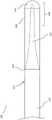
图1示出了具有芯102的示例性导丝装置100。管104联接到芯102并从与芯102的附接点向远侧延伸。如图所示,芯102的远侧区段延伸到管104中,并且被管104围绕。在一些实施例中,芯102包括一个或多个逐渐变细的区段,使得芯102能够装配在管104内并延伸到所述管中。例如,芯102的远侧区段可以被研磨,以便逐渐变细为远端处的更小直径。在该示例中,芯102和管104在它们相邻并彼此附接的附接点103处具有基本上相似的外径。FIG. 1 shows an
管104以允许扭转力从芯102传递到管104并由此进一步通过管104向远侧传递的方式联接到芯102(如,使用粘合剂、钎焊(soldering)和/或焊接(welding))。医用级粘合剂120可用于在装置远端处将管104联接到芯线102并形成无创伤覆盖物。如下面更详细地解释的,管104被微制造成包括多个切口。切口布置成形成一切口图案,该切口图案可有利地在导丝装置100的远侧末端附近提供有效的可成形性,同时还保持良好的扭转能力。为清楚起见,在图1和图2中未示出切口图案。在图3至图5中示出了可在管104中使用的切口图案的示例。
导丝装置100的近侧区段110向近侧延伸至一长度,该长度为提供足够的导丝长度以递送至目标解剖区域所需的。近侧区段110通常具有约50cm至300cm范围内的长度。近侧区段110可具有约0.014英寸的直径,或约0.008英寸至0.125英寸范围内的直径。芯102的远侧区段112可以逐渐变细至约0.002英寸的直径,或者约0.001英寸至0.050英寸范围内的直径。在一些实施例中,管104的长度在约3cm至100cm的范围内。The
在一些实施例中,芯102的远侧区段112逐渐变细为圆形横截面。在其他实施例中,芯102的远侧区段112具有扁平或矩形横截面。远侧区段112还可以具有另一横截面形状,诸如另一多边形形状、卵形形状、不规则形状,或沿着其长度的不同区域的不同横截面形状的组合。In some embodiments, the
通常,使用者将通过手动弯折、扭曲或以其他方式将导丝装置100的远端(约)1cm至3cm处理成期望形状来成形导丝装置100的远端。在图1中该长度示意性地示出为远侧“末端”106。在一些实施例中,末端106包括由不锈钢、铂和/或其他可成形材料形成的一个或多个可成形部件(在管104内)。在优选实施例中,末端106包括由具有加工硬化特性的材料形成的一个或多个部件,使得末端在成形(即,塑性变形)时在成形区段提供比成形之前更高的弹性模量。Typically, the user will shape the distal end of the
图2示出了图1的导丝装置100的横截面视图。如图所示,芯102包括近侧区段110和远侧区段112,远侧区段的直径小于近侧区段110的直径。线圈114位于芯102的远侧区段112的至少一部分上。线圈114优选地由一种或多种不透射线的材料形成,诸如铂族、金、银、钯、铱、锇、钽、钨、铋、镝、钆等等。另外或替代地,线圈114可以至少部分地由不锈钢或由在被使用者弯折或以其他方式处理之后能有效地保持形状的其他材料形成。在示出的实施例中,线圈114设置在装置的远端处或其附近,并且朝向附接点103向近侧延伸一段距离。在一些实施例中,线圈114的长度基本上与管104的长度一致。在其他实施例中,线圈114较短。例如,线圈114可以从远端延伸1cm、2cm、4cm、6cm、8cm、10cm、12cm、15cm、20cm、25cm、30cm或35cm,或者可以从近端延伸由前述值中的任何两个限定的范围中的一段距离。FIG. 2 shows a cross-sectional view of the
在一些实施例中,线圈114形成为一个整体件。在其他实施例中,线圈114包括彼此相邻定位和/或通过相互交织的线圈互锁的多个独立区段。另外或替代地,这些独立区段可以钎焊、粘附或以其他方式紧固至彼此以形成完整的线圈114。In some embodiments, the
尽管所示实施例示出了线圈114与管104之间的空间,但是应该理解,这是为了便于可视性而示意性地示出的。在一些实施例中,线圈114的尺寸设计成充塞远侧区段112与管104之间的较大比例的空间。例如,线圈114的尺寸可以设计成紧靠芯102的远侧区段112和管104的内表面两者。其他实施例在芯102与管104之间包括用于导丝装置100的区段的至少一部分的空间,管104和芯102在此处共同延伸。Although the illustrated embodiment shows the space between the
线圈114可以有利地用于填塞芯102与管104之间的空间,以使芯102的远侧区段112的曲率与管104的曲率一致(align with,对准)。例如,当在管104中形成曲率时,紧密填塞的线圈114的区段用作管104与远侧区段112之间的填塞物,以赋予远侧区段112相同的曲率。相反,省却了线圈的导丝装置当在管处弯曲时不会遵循与管相同的弯曲,而是会延伸直到抵靠管的内表面,之后被迫弯曲。The
本文描述的实施例有利地允许远侧末端106成形为期望的位姿(position)并且在成形位姿保持足够长的一段时间。与传统的导丝装置相比,所示的实施例能够形成和保持成形构造。对于传统的导丝装置,经常会由于管结构与内部组件(芯和线圈)之间的特性不匹配而出现与可成形性有关的问题。管结构通常由镍钛诺或其他超弹性材料形成。所述管在弯折或成形时将偏向其原始(直线)位姿,并因此将在任何可成形的内部部件上施加恢复力,导致变形和末端的定制形状的损失。The embodiments described herein advantageously allow the
通常,例如,传统的导丝在部署之前将具有成形的末端,但是在导丝的使用期间成形的末端将损失或退化,因为超弹性管朝向其与期望的末端形状相反的原始形状折曲。因此,由管赋予的恢复力不利地作用于(act against)内部部件,从而减少或退化使用者设定的期望形状。相比之下,本文描述的实施例包括的特征使得末端106能够被成形而不受来自管的主导的(overriding)恢复力。如下所述,管104可包括切口图案,该切口图案保持有效的扭转能力,同时还在远侧末端106处提供足够的柔性,以避免破坏末端106的定制形状。Typically, for example, a conventional guidewire will have a shaped tip prior to deployment, but the shaped tip will be lost or degraded during use of the guidewire as the superelastic tube flexes towards its original shape opposite the desired tip shape. Thus, the restoring force imparted by the tube adversely acts against the internal components, thereby reducing or degrading the desired shape set by the user. In contrast, the embodiments described herein include features that enable the
图3至图7示出了可以用在本文描述的一个或多个导丝装置实施例中的管切口图案的示例性实施例。例如,可以根据图3至图7中所示的一种或多种构造来切割图1和图2中所示的实施例的管104。Figures 3-7 illustrate exemplary embodiments of cannula cut patterns that may be used in one or more of the guidewire device embodiments described herein. For example, the
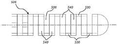
图3示出了具有一系列切口508的管504,所述切口形成梁530(轴向延伸)和环540(横向和周向延伸)。在所示的实施例中,切口508作为一系列“旁路切口”布置在管上。当用在本文中时,旁路切口是这样的切口:在相对于管的纵向轴线与其直接相对的位置没有相对的切口,因此,在横向和周向延伸的材料的环540之间留有纵向延伸材料的单个梁530。“旁路”切口图案在本文中也可称为“单梁”切口图案。在所示的实施例中,切口布置为交替切口,从一个切口到下一个切口沿着管504的长度偏移大约180度。Figure 3 shows the
使用如所示的旁路(即,单梁)切口的一个或多个区段形成的管可提供许多益处,特别是关于导丝装置的相关可成形末端提供许多益处。例如,具有旁路切口的管的柔性相对地大于没有切口或具有在连续环之间留有多个梁的切口的管的柔性(如,假设梁宽度、环尺寸和切口间距原本是相等的)。有益地,由旁路切口布置提供的增加的柔性阻止或最小化管导致导丝的内部结构的形状变形。例如,设置在管内的芯(例如不锈钢)可以弯折或弯曲(即,塑性变形),以便为导丝的末端提供期望的形状。A tube formed using one or more sections of bypass (ie, single beam) cuts as shown may provide many benefits, particularly with respect to the associated formable tip of a guidewire device. For example, a tube with bypass cuts is relatively more flexible than a tube without cuts or with cuts that leave multiple beams between successive rings (eg, assuming beam width, ring size, and cut spacing would have been equal) . Beneficially, the increased flexibility provided by the bypass incision arrangement prevents or minimizes shape deformation of the inner structure of the guidewire caused by the tube. For example, a core (eg, stainless steel) disposed within the tube may be bent or bent (ie, plastically deformed) to provide the desired shape to the tip of the guidewire.
如上所述,在许多情况下,与管的弹性恢复相关的力将被施加在成形芯上并且将倾向于至少相对于成形芯的被布置在管内的部分使成形芯变直。因此,适当地调节管的柔性会降低施加在成形芯上的恢复力,并使成形芯能更好地保持其形状。As mentioned above, in many cases the forces associated with the elastic recovery of the tube will be exerted on the forming core and will tend to straighten the forming core at least relative to the portion of the forming core that is disposed within the tube. Therefore, properly adjusting the flexibility of the tube will reduce the restoring force exerted on the forming core and allow the forming core to better retain its shape.
在一些实施例中,对于朝向远端移动的每个连续切口或多组切口,连续的旁路切口或多组旁路切口的深度逐渐增加。因此,可利用切口深度轮廓来构造对于给定应用具有期望的柔性和扭转能力特性的管。例如,一种管构造可包括具有相对较低的柔性和相对较高的扭转能力的近侧区段,所述近侧区段随着旁路切口快速地朝向远端逐渐变深而快速地进展为具有相对较高的柔性和相对较低的扭转能力的远侧区段。在一些实施例中,具有相对较深切口的区段仅形成在管的最远侧区段处,在所述最远侧区段处可成形性是预期的或期望的(例如,管的远端1cm至3cm),以便对管的其余部分保持更高的扭转能力。In some embodiments, for each successive incision or groups of incisions moved distally, the successive bypass incisions or groups of bypass incisions gradually increase in depth. Accordingly, the cut depth profile can be utilized to construct a tube having the desired flexibility and torsional capability characteristics for a given application. For example, one tube configuration may include a proximal section with relatively low flexibility and relatively high torsional capability that progresses rapidly as the bypass incision rapidly deepens toward the distal end is the distal section with relatively high flexibility and relatively low torsional capacity. In some embodiments, the section with the relatively deep cut is formed only at the distal-most section of the tube where formability is expected or desired (eg, the distal end of the tube end 1cm to 3cm) in order to maintain a higher twisting capacity to the rest of the tube.
旁路切口508可以根据深度、宽度和/或间隔而变化。例如,随着切口508越接近装置的远侧末端,切口可以逐渐变得越深和/或间隔越紧密。更深和/或间隔更紧密的切口提供相对更大的柔性。因此,可以形成梯度,其在导丝的逐渐更远侧的区域增加导丝柔性。如下面更详细描述的,旁路切口508也可以根据施加在每个相邻切口处或施加在相邻切口组处的角度偏移以交替的角度位置来布置。所示实施例示出了从一个切口到下一个切口的180度的角度偏移。一些实施例可包括从一个切口到下一个切口或从一组切口到下一组切口的约5度、15度、30度、45度、60度、75度、80度、或85度的角度偏移。The bypass cuts 508 may vary according to depth, width and/or spacing. For example, the incisions may gradually become deeper and/or more closely spaced as the
图4示出了管604的另一实施例,该管具有旁路切口和设置在该旁路切口近侧的一组相对的、深度偏移的双梁切口。在所示的实施例中,一组旁路切口产生梁630。梁630的近侧是布置为相对的切口的一组切口,所述相对的切口产生梁634。虽然在该视图中不可见,但是在每个梁634的对面形成有另外的梁(在该视图中被挡在梁634后面)。因此,深度偏移的双梁切口图案内的每个环640具有将该环连接到其近侧相邻的环的一组两个梁以及将该环连接到远侧相邻的环的一组两个梁。FIG. 4 shows another embodiment of a
如图所示,相对的双梁切口在深度上偏移,使得对于每对相对的切口(在管轴线的每一侧上具有一个切口),其中一个切口的深度大于相对切口的深度。这种深度偏移的双梁切口可以有利地用于从一段旁路切口(诸如图3中所示的)过渡到一段非偏移的相对的双梁切口(诸如图5中所示)。As shown, the opposing double beam cuts are offset in depth such that for each pair of opposing cuts (one cut on each side of the tube axis), one cut has a greater depth than the opposing cut. Such deeply offset double beam cuts can be advantageously used to transition from a segment of bypass cuts (such as shown in FIG. 3 ) to a length of non-offset opposing double beam cuts (such as shown in FIG. 5 ).
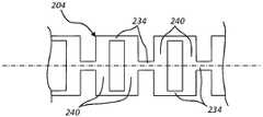
图5示出了具有双梁切口图案的管204的区段,每对相对的切口中的每个切口具有大约相同的切口深度,使得所得到的梁基本等距地周向间隔开。如图所示,切口导致在每个环240之间形成一对梁234。这里示出的切口从一对相对的切口到下一对相对的切口成角度地偏移约90度,尽管也可以利用其他角度偏移。Figure 5 shows a section of
具有带有基本周向等距间隔的梁的双梁切口图案的管的区段通常具有相对较高的传递扭矩的能力和相对较低的柔性,而具有旁路切口的管的区段通常具有相对较低的传递扭矩的能力和相对较高的柔性。具有深度偏移的双梁切口构造的管的区段具有的扭矩传递性和柔性,通常介于深度对称的相对的双梁切口的区段的扭矩传递性和柔性与旁路切口的区段的扭矩传递性和柔性之间。相对的切口的深度之间的差异越大,所得到的梁在周向上将越靠近,并且因此偏移双梁切口将越类似于单梁/旁路切口。同样,相对的切口的深度越相似,偏移双梁切口与对称双梁切口越相似。Sections of tubes with a double beam cut pattern with substantially circumferentially equally spaced beams typically have a relatively high torque transfer capability and relatively low flexibility, while sections of tubes with bypass cuts generally have Relatively low ability to transmit torque and relatively high flexibility. The torque transmissibility and flexibility of a section of a tube with a depth-offset double beam cut configuration is typically between those of a depth symmetric opposing double beam cut section and that of a bypass cut section. Between torque transmissibility and flexibility. The greater the difference between the depths of the opposing cuts, the closer the resulting beams will be circumferentially, and thus the more similar the offset double beam cuts will be to the single beam/bypass cuts. Likewise, the more similar the depths of the opposing cuts, the more similar the offset double beam cut is to the symmetrical double beam cut.
包括偏移双梁区段的管的实施例有利地提供一过渡区域,该过渡区域可被定位和构造成在远侧旁路切口区与近侧对称双梁区段之间提供期望的过渡特性。例如,过渡区可以是相对渐进的或突然的,这取决于过渡区的长度和/或取决于连续切口中的偏移的变化的快速性。因此,管可被构造成给近侧区段提供更大扭转能力和更小柔性,其向具有更大柔性的更柔韧的远侧区段过渡,以在由操作者使其成形时更好地保持弯折形状。近侧区段、过渡区段和远侧区段的位置和构造是可调的,以最优化有效扭转能力和可成形末端性能的益处。Embodiments of the tube comprising offset double beam sections advantageously provide a transition region that can be positioned and configured to provide desired transition characteristics between the distal bypass cutout region and the proximal symmetrical double beam section . For example, the transition zone may be relatively gradual or abrupt, depending on the length of the transition zone and/or on the rapidity of the change in offset in successive cuts. Accordingly, the tube can be configured to provide greater torsional capability and less flexibility to the proximal section, which transitions to a more flexible distal section with greater flexibility to better allow it to be shaped by the operator Keep the bent shape. The position and configuration of the proximal section, transition section and distal section are adjustable to optimize the benefits of effective torsion capability and formable tip performance.
图6示出了管704的另一实施例,其具有形成多个梁730和环740的单梁切口。如图所示,切口布置成使得梁730沿管704的一侧对齐,而不是以180度或一些其他角度量被交替定位。这样的实施例可以有利地在一个方向上(如,朝向对齐的梁730)提供优先弯折,使得背向管的轴线的相关恢复力进一步最小化。FIG. 6 shows another embodiment of a
图7示出了管304的实施例,其具有旁路切口图案和多组切口之间的角度偏移。如图所示,角度偏移使所得到的梁330沿着管区段的长度呈旋转/螺旋圆周图案定位。在一些实施例中,在一组切口中从一个切口到下一个切口施加第一角度偏移,并且从一组切口到下一组切口施加第二角度偏移。例如,如图7所示,一对相邻切口中的每个切口308可以偏移约180度,以便相对于导丝的纵向轴线在彼此的相对侧上留下所形成的梁330,同时每对从相邻对偏移一些其他角度(如,在所示实施例中约为5度)。以这种方式,内部设定的角度偏移可以将梁330定位在导丝轴线的相对侧上,而中间设定(inter-set)的角度偏移可以将连续梁的角度位置调整成足以在一段若干组切口308上最小化导丝的优选弯折方向。FIG. 7 shows an embodiment of a
旋转偏移也可以应用于图3至图6中所示的切口图案。在优选实施例中,沿着给定区段长度的每个连续切口或切口组(例如,每两个切口、每三个切口、每四个切口等)可旋转地偏移大约1度、2度、3度、5度或10度,或者在双梁构造中从90度偏移大约1度、2度、3度、5度或10度,或在单梁构造中从180度偏离1度、2度、3度、5度或10度。这些旋转偏移值有利地显示出消除折曲偏差的良好能力。Rotational offsets can also be applied to the cutout patterns shown in FIGS. 3-6 . In a preferred embodiment, each successive cut or set of cuts (eg, every second cut, every third cut, every fourth cut, etc.) along a given segment length is rotatably offset by approximately 1 degree, 2 degrees, 3 degrees, 5 degrees, or 10 degrees, or approximately 1, 2, 3, 5, or 10 degrees offset from 90 degrees in a double beam configuration, or 1 degree offset from 180 degrees in a single beam configuration , 2 degrees, 3 degrees, 5 degrees or 10 degrees. These rotational offset values advantageously show a good ability to eliminate bending bias.
例如,在双梁切口图案中,其中每对梁在周向上等距间隔,诸如图5所示,从90度离开约1度、2度、3度、5度或10度的旋转偏移使沿着切口区段长度的每两对梁定位成彼此错位几度。例如,第二对梁可以从第一对梁旋转地偏移得略微大于或小于90度,但是第三对梁将仅从第一对梁旋转地偏移几度,并且第四对梁将仅从第二对梁旋转地偏移几度。当沿着导丝装置的切口区段的长度以这种方式布置若干连续对梁时,所得到的结构允许切口图案增强柔性而不会引入或加重任何定向柔性偏差。For example, in a double beam cut pattern, where each pair of beams is equally spaced circumferentially, such as shown in Figure 5, a rotational offset of about 1, 2, 3, 5, or 10 degrees from 90 degrees causes the Every two pairs of beams for the length of the cut-out section are positioned offset from each other by a few degrees. For example, the second pair of beams could be rotationally offset slightly more or less than 90 degrees from the first pair of beams, but the third pair of beams would be rotationally offset from the first pair by only a few degrees, and the fourth pair of beams would only be offset from the first pair by a few degrees. Rotationally offset a few degrees from the second pair of beams. When several consecutive pairs of beams are arranged in this manner along the length of the slit section of the guidewire device, the resulting structure allows the slit pattern to enhance flexibility without introducing or exacerbating any directional flexibility deviations.
图3至图7中所示的管实施例的独立的部件和特征可以组合以形成不同的管构造。例如,一些管可以构造成具有旁路(单梁)切口的区段(如图3、图6和/或图7中所示)以及对称间隔的双梁切口的区段(如图5所示),可选地还具有一个或多个深度偏移双梁切口(如图4所示)。例如,一些管的实施例可包括具有对称间隔的双梁切口图案的近侧区段,该近侧区段过渡到具有旁路切口布置的远侧区段。The individual components and features of the tube embodiments shown in Figures 3-7 can be combined to form different tube configurations. For example, some tubes may be constructed with sections of bypass (single beam) cuts (as shown in FIGS. 3 , 6 and/or 7 ) and sections of symmetrically spaced double beam cuts (as shown in FIG. 5 ) ), optionally with one or more depth offset double beam cuts (as shown in Figure 4). For example, some tube embodiments may include a proximal section with a symmetrically spaced double beam cut pattern transitioning to a distal section with a bypass cut arrangement.
本文所述的实施例可以有利地使得管的更近侧区域能够传递相对更大的扭矩,同时降低管的更远侧区段的扭转能力以允许没有过度牺牲扭转能力的末端成形。于是,导丝装置的特征可以调整到特定需要或应用,以最优化扭转能力与末端可成形性之间的操作关系。Embodiments described herein may advantageously enable a more proximal region of the tube to transmit relatively greater torque, while reducing the torsional capability of the more distal section of the tube to allow tip shaping without unduly sacrificing torsional capability. Thus, the characteristics of the guidewire device can be tailored to specific needs or applications to optimize the operational relationship between torsion capability and tip formability.
在优选实施例中,芯的可成形远侧区段具有刚度,该刚度能够承受远侧区段成形之后作用在芯的该远侧区段上的来自管的预期弯曲力。在一些实施例中,芯的可成形远侧区段由提供的弹性模量大于用于形成管的材料的弹性模量约1.5至4倍(或约2至3倍)的一种材料或多种材料的组合形成。In a preferred embodiment, the formable distal section of the core has a rigidity capable of withstanding the expected bending forces from the tube acting on the distal section of the core after forming the distal section. In some embodiments, the formable distal section of the core is comprised of a material or materials that provide a modulus of elasticity that is about 1.5 to 4 times (or about 2 to 3 times) greater than the modulus of elasticity of the material used to form the tube A combination of materials is formed.
本文使用的术语“大约”、“约”和“基本上”表示接近所述量或条件的量或条件,其仍然执行期望的功能或实现期望的结果。例如,术语“大约”、“约”和“基本上”可以指从所述量或条件偏离小于10%,或小于5%,或小于1%,或小于0.1%,或小于0.01%的量或条件。As used herein, the terms "about", "about" and "substantially" mean an amount or condition that approximates the stated amount or condition, which still performs the desired function or achieves the desired result. For example, the terms "about", "about" and "substantially" can refer to an amount that deviates from the stated amount or condition by less than 10%, or less than 5%, or less than 1%, or less than 0.1%, or less than 0.01%, or condition.
相对于本文描绘和/或描述的任何实施例所描述的元件可以与相对于本文描绘和/或描述的任何其他实施例所描述的元件组合。例如,相对于图3至图7中任一个的管区段描述的任何元件可以组合并用于形成图1和图2的导丝装置的管104。另外,实施例可以包括具有多个如本文所述的旁路切口、深度偏移双梁切口和/或深度对称的双梁切口的管。在任何前述组合中,芯线的远侧末端可以是圆形的、扁平的或其他形状。Elements described with respect to any embodiment depicted and/or described herein may be combined with elements described with respect to any other embodiment depicted and/or described herein. For example, any of the elements described with respect to the tube section of any of FIGS. 3-7 may be combined and used to form the
在不脱离本发明的构思或基本特征的情况下,本发明可以以其他形式实施。所描述的实施例在所有方面都应被视为仅是说明性的而非限制性的。因此,本发明的范围由所附权利要求而不是前面的描述表示。落在权利要求的含义和等同范围内的所有变化都包括在其范围内。The present invention may be embodied in other forms without departing from the spirit or essential characteristics of the present invention. The described embodiments are to be considered in all respects only as illustrative and not restrictive. Accordingly, the scope of the invention is indicated by the appended claims rather than the foregoing description. All changes that come within the meaning and equivalency range of the claims are included within their scope.
Claims (14)
Applications Claiming Priority (6)
| Application Number | Priority Date | Filing Date | Title |
|---|---|---|---|
| US201662363760P | 2016-07-18 | 2016-07-18 | |
| US62/363,760 | 2016-07-18 | ||
| US15/606,607US11207502B2 (en) | 2016-07-18 | 2017-05-26 | Guidewire devices having shapeable tips and bypass cuts |
| US15/606,607 | 2017-05-26 | ||
| PCT/US2017/041299WO2018017349A1 (en) | 2016-07-18 | 2017-07-10 | Guidewire devices having shapeable tips and bypass cuts |
| CN201780057228.6ACN109715245B (en) | 2016-07-18 | 2017-07-10 | Guidewire device with formable tip and bypass incision |
Related Parent Applications (1)
| Application Number | Title | Priority Date | Filing Date |
|---|---|---|---|
| CN201780057228.6ADivisionCN109715245B (en) | 2016-07-18 | 2017-07-10 | Guidewire device with formable tip and bypass incision |
Publications (1)
| Publication Number | Publication Date |
|---|---|
| CN114733045Atrue CN114733045A (en) | 2022-07-12 |
Family
ID=60941636
Family Applications (5)
| Application Number | Title | Priority Date | Filing Date |
|---|---|---|---|
| CN201780057228.6AActiveCN109715245B (en) | 2016-07-18 | 2017-07-10 | Guidewire device with formable tip and bypass incision |
| CN201780057216.3AActiveCN109789296B (en) | 2016-07-18 | 2017-07-10 | Guidewire device with distally extending coil and formable tip |
| CN202211119903.2APendingCN115414571A (en) | 2016-07-18 | 2017-07-10 | Guidewire device with shapeable polymer tip |
| CN202210374637.1APendingCN114733045A (en) | 2016-07-18 | 2017-07-10 | Guidewire device with shapeable tip and bypass incision |
| CN201780057199.3AActiveCN109789295B (en) | 2016-07-18 | 2017-07-10 | Guidewire device with shapeable polymer tip |
Family Applications Before (3)
| Application Number | Title | Priority Date | Filing Date |
|---|---|---|---|
| CN201780057228.6AActiveCN109715245B (en) | 2016-07-18 | 2017-07-10 | Guidewire device with formable tip and bypass incision |
| CN201780057216.3AActiveCN109789296B (en) | 2016-07-18 | 2017-07-10 | Guidewire device with distally extending coil and formable tip |
| CN202211119903.2APendingCN115414571A (en) | 2016-07-18 | 2017-07-10 | Guidewire device with shapeable polymer tip |
Family Applications After (1)
| Application Number | Title | Priority Date | Filing Date |
|---|---|---|---|
| CN201780057199.3AActiveCN109789295B (en) | 2016-07-18 | 2017-07-10 | Guidewire device with shapeable polymer tip |
Country Status (9)
| Country | Link |
|---|---|
| US (5) | US11207502B2 (en) |
| EP (3) | EP3484570A4 (en) |
| JP (6) | JP7050745B2 (en) |
| KR (5) | KR102528851B1 (en) |
| CN (5) | CN109715245B (en) |
| AU (3) | AU2017299456B2 (en) |
| CA (3) | CA3031353A1 (en) |
| CR (3) | CR20190092A (en) |
| WO (3) | WO2018017349A1 (en) |
Families Citing this family (33)
| Publication number | Priority date | Publication date | Assignee | Title |
|---|---|---|---|---|
| US11406791B2 (en) | 2009-04-03 | 2022-08-09 | Scientia Vascular, Inc. | Micro-fabricated guidewire devices having varying diameters |
| WO2010077692A2 (en) | 2008-12-08 | 2010-07-08 | Scientia Vascular Llc | Micro-cutting machine for forming cuts in products |
| US10363389B2 (en) | 2009-04-03 | 2019-07-30 | Scientia Vascular, Llc | Micro-fabricated guidewire devices having varying diameters |
| US12220538B2 (en) | 2008-12-08 | 2025-02-11 | Scientia Vascular, Inc. | Micro-fabricated intravascular devices having varying diameters |
| US11207502B2 (en) | 2016-07-18 | 2021-12-28 | Scientia Vascular, Llc | Guidewire devices having shapeable tips and bypass cuts |
| US11052228B2 (en) | 2016-07-18 | 2021-07-06 | Scientia Vascular, Llc | Guidewire devices having shapeable tips and bypass cuts |
| US10646689B2 (en) | 2016-07-29 | 2020-05-12 | Cephea Valve Technologies, Inc. | Mechanical interlock for catheters |
| US10821268B2 (en) | 2016-09-14 | 2020-11-03 | Scientia Vascular, Llc | Integrated coil vascular devices |
| US11452541B2 (en) | 2016-12-22 | 2022-09-27 | Scientia Vascular, Inc. | Intravascular device having a selectively deflectable tip |
| ES2966345T3 (en) | 2017-05-26 | 2024-04-22 | Scientia Vascular Inc | Microfabricated medical device with a non-helical cutting arrangement |
| US11305095B2 (en) | 2018-02-22 | 2022-04-19 | Scientia Vascular, Llc | Microfabricated catheter having an intermediate preferred bending section |
| EP3746169B1 (en)* | 2018-03-09 | 2024-07-24 | Scientia Vascular, Inc. | Guidewire devices having shapeable tips and bypass cuts |
| US12011555B2 (en)* | 2019-01-15 | 2024-06-18 | Scientia Vascular, Inc. | Guidewire with core centering mechanism |
| US11766539B2 (en) | 2019-03-29 | 2023-09-26 | Incept, Llc | Enhanced flexibility neurovascular catheter |
| WO2020206101A1 (en) | 2019-04-05 | 2020-10-08 | Traverse Vascular, Inc. | Reentry catheters for traversing chronic total occlusions |
| JP7260408B2 (en)* | 2019-06-14 | 2023-04-18 | 株式会社パイオラックスメディカルデバイス | Slit pipe and guide wire using it |
| US11918298B2 (en)* | 2019-09-12 | 2024-03-05 | Biosense Webster (Israel) Ltd. | Very narrow probe with coil |
| US11478609B2 (en)* | 2019-09-26 | 2022-10-25 | Biosense Webster (Israel) Ltd. | Bendable guidewire |
| US12005205B2 (en)* | 2019-12-16 | 2024-06-11 | Stryker Corporation | Guidewires for medical devices |
| US12343485B2 (en) | 2020-01-23 | 2025-07-01 | Scientia Vascular, Inc. | High torque guidewire device |
| US12178975B2 (en)* | 2020-01-23 | 2024-12-31 | Scientia Vascular, Inc. | Guidewire having enlarged, micro-fabricated distal section |
| EP4151671B1 (en) | 2020-05-11 | 2025-04-30 | National University Corporation Kobe University | Method for producing polyurethane |
| KR102247637B1 (en) | 2020-07-10 | 2021-05-03 | 주식회사 레노메디컬 | Electrolytic-polished core wire and core wire electrolytic polishing device |
| US12296112B2 (en) | 2020-10-05 | 2025-05-13 | Scientia Vascular, Inc. | Microfabricated catheter devices with high axial strength |
| CA3204517A1 (en)* | 2021-01-21 | 2022-07-28 | John A. Lippert | High torque guidewire device |
| CN113041159A (en)* | 2021-03-23 | 2021-06-29 | 昆明医科大学第二附属医院 | Novel stomach tube convenient to put into pylorus |
| JP7748835B2 (en)* | 2021-09-07 | 2025-10-03 | テルモ株式会社 | Guidewire |
| EP4428179A1 (en) | 2021-11-02 | 2024-09-11 | National University Corporation Kobe University | Polyurethane production method |
| KR102722198B1 (en)* | 2022-04-08 | 2024-10-25 | 성원메디칼 주식회사 | Medical Micro Guide Wire |
| US20240216653A1 (en)* | 2022-12-21 | 2024-07-04 | Scientia Vascular, Inc. | Intravascular device with a matched diameter core wire joint |
| US20240342444A1 (en)* | 2023-04-13 | 2024-10-17 | Scientia Vascular, Inc. | Soft-tip intravascular devices |
| CN119302785A (en)* | 2023-07-06 | 2025-01-14 | 深圳市英耐特医疗科技有限公司 | Conveying device and conveying system |
| US12171917B1 (en) | 2024-01-08 | 2024-12-24 | Imperative Care, Inc. | Devices for blood capture and reintroduction during aspiration procedure |
Citations (12)
| Publication number | Priority date | Publication date | Assignee | Title |
|---|---|---|---|---|
| US5797857A (en)* | 1993-12-24 | 1998-08-25 | Terumo Kabushiki Kaisha | Guide wire |
| US5833631A (en)* | 1996-06-28 | 1998-11-10 | Target Therapeutics, Inc. | Fiber tip guidewire |
| US20020013540A1 (en)* | 1999-12-22 | 2002-01-31 | Jacobsen Stephen C. | Coronary guidewire system |
| US20050065456A1 (en)* | 2003-09-22 | 2005-03-24 | Scimed Life Systems, Inc. | Guidewire with reinforcing member |
| US20070135763A1 (en)* | 2005-12-12 | 2007-06-14 | Musbach Frank A | Micromachined medical devices |
| US20080064989A1 (en)* | 2006-09-13 | 2008-03-13 | Boston Scientific Scimed, Inc. | Crossing guidewire |
| US20080188928A1 (en)* | 2005-09-16 | 2008-08-07 | Amr Salahieh | Medical device delivery sheath |
| US20090177119A1 (en)* | 2008-01-03 | 2009-07-09 | Boston Scientific Scimed, Inc. | Articulating intracorporeal medical device |
| US20100145308A1 (en)* | 2008-12-10 | 2010-06-10 | Boston Scientific Scimed, Inc. | Medical devices with a slotted tubular member having improved stress distribution |
| US20130144267A1 (en)* | 2011-12-05 | 2013-06-06 | Stryker Nv Operations Limited | Reinforced elongate medical device and method of manufacture |
| CN103301553A (en)* | 2012-02-28 | 2013-09-18 | 科维蒂恩有限合伙公司 | Intravascular guidewire |
| CN105582611A (en)* | 2014-09-04 | 2016-05-18 | 雅培心血管系统有限公司 | Balloon Catheter |
Family Cites Families (452)
| Publication number | Priority date | Publication date | Assignee | Title |
|---|---|---|---|---|
| US2022065A (en) | 1932-07-07 | 1935-11-26 | Frederick C Wappler | Therapeutic applicator device |
| US2187299A (en) | 1935-08-13 | 1940-01-16 | Burkhardt Otto Wilhelm | Dressing of individual blocks of stone |
| US3183702A (en) | 1960-11-21 | 1965-05-18 | Rca Corp | Method of and apparatus for cutting and deburring tubes |
| US3612058A (en) | 1968-04-17 | 1971-10-12 | Electro Catheter Corp | Catheter stylets |
| US3572334A (en) | 1968-11-27 | 1971-03-23 | Johnson & Johnson | Intravenous catheter placement unit |
| JPS4845313Y1 (en) | 1969-08-06 | 1973-12-26 | ||
| JPS485208Y1 (en) | 1970-07-28 | 1973-02-09 | ||
| US3920058A (en) | 1971-02-22 | 1975-11-18 | Willard H Walker | Method of sawing logs |
| US3709271A (en) | 1971-07-01 | 1973-01-09 | Mc Farland L Co | Method and apparatus for deep incising poles |
| US3782233A (en) | 1971-11-12 | 1974-01-01 | Smithe Machine Co Inc F L | Rotatable cutter mechanism for cutting different length notches in a moving web |
| US4163406A (en) | 1977-12-15 | 1979-08-07 | Genevieve I. Hanscom | Centering device for feeding articles to a food slicer |
| US4239069A (en) | 1979-08-10 | 1980-12-16 | Zimmerman Edwin H | Automatic cant production machine |
| SE419059B (en) | 1980-07-03 | 1981-07-13 | Kockums Ind Ab | CONTROL DEVICE ON THE SAW SHEET'S SUPPLIED SUBDIVISION MACHINERY FOR WORK |
| US5506682A (en) | 1982-02-16 | 1996-04-09 | Sensor Adaptive Machines Inc. | Robot vision using targets |
| JPS59102509A (en) | 1983-11-21 | 1984-06-13 | Fujikawa Seikou Kk | Double-acting multihead type drilling and slotting device |
| US4801297A (en) | 1984-06-01 | 1989-01-31 | Edward Weck Incorporated | Catheter having slit tip |
| EP0186201B1 (en) | 1984-12-27 | 1992-12-30 | Disco Abrasive Systems, Ltd. | Semiconductor wafer dicing machine |
| US5102390A (en) | 1985-05-02 | 1992-04-07 | C. R. Bard, Inc. | Microdilatation probe and system for performing angioplasty in highly stenosed blood vessels |
| US4719924A (en) | 1986-09-09 | 1988-01-19 | C. R. Bard, Inc. | Small diameter steerable guidewire with adjustable tip |
| US4989608A (en) | 1987-07-02 | 1991-02-05 | Ratner Adam V | Device construction and method facilitating magnetic resonance imaging of foreign objects in a body |
| US4846186A (en) | 1988-01-12 | 1989-07-11 | Cordis Corporation | Flexible guidewire |
| US4895168A (en) | 1988-01-21 | 1990-01-23 | Schneider (Usa) Inc., A Pfizer Company | Guidewire with movable core and external tubular safety cover |
| US5507751A (en) | 1988-11-09 | 1996-04-16 | Cook Pacemaker Corporation | Locally flexible dilator sheath |
| US5372587A (en) | 1989-01-09 | 1994-12-13 | Pilot Cariovascular Systems, Inc. | Steerable medical device |
| US5047045A (en) | 1989-04-13 | 1991-09-10 | Scimed Life Systems, Inc. | Multi-section coaxial angioplasty catheter |
| US5144959A (en) | 1989-08-15 | 1992-09-08 | C. R. Bard, Inc. | Catheter guidewire with varying radiopacity |
| US5084022A (en) | 1989-10-04 | 1992-01-28 | Lake Region Manufacturing Company, Inc. | Graduated guidewire |
| US5095915A (en) | 1990-03-19 | 1992-03-17 | Target Therapeutics | Guidewire with flexible distal tip |
| US5147317A (en) | 1990-06-04 | 1992-09-15 | C.R. Bard, Inc. | Low friction varied radiopacity guidewire |
| US5069217A (en) | 1990-07-09 | 1991-12-03 | Lake Region Manufacturing Co., Inc. | Steerable guide wire |
| US5345945A (en) | 1990-08-29 | 1994-09-13 | Baxter International Inc. | Dual coil guidewire with radiopaque distal tip |
| EP0556316B1 (en) | 1990-11-09 | 1997-01-22 | Boston Scientific Corporation | Guidewire for crossing occlusions in blood vessels |
| US5174302A (en) | 1990-12-04 | 1992-12-29 | Cordis Corporation | Variable radiopacity guidewire with spaced highly radiopaque regions |
| AU660444B2 (en) | 1991-02-15 | 1995-06-29 | Ingemar H. Lundquist | Torquable catheter and method |
| US5315996A (en) | 1991-02-15 | 1994-05-31 | Lundquist Ingemar H | Torquable catheter and method |
| US5454787A (en) | 1991-02-15 | 1995-10-03 | Lundquist; Ingemar H. | Torquable tubular assembly and torquable catheter utilizing the same |
| US5154725A (en) | 1991-06-07 | 1992-10-13 | Advanced Cardiovascular Systems, Inc. | Easily exchangeable catheter system |
| US6027863A (en) | 1991-09-05 | 2000-02-22 | Intratherapeutics, Inc. | Method for manufacturing a tubular medical device |
| US5741429A (en) | 1991-09-05 | 1998-04-21 | Cardia Catheter Company | Flexible tubular device for use in medical applications |
| CA2117088A1 (en) | 1991-09-05 | 1993-03-18 | David R. Holmes | Flexible tubular device for use in medical applications |
| WO1993013704A1 (en) | 1992-01-09 | 1993-07-22 | Endomedix Corporation | Bi-directional miniscope |
| US5437288A (en) | 1992-09-04 | 1995-08-01 | Mayo Foundation For Medical Education And Research | Flexible catheter guidewire |
| IL106946A0 (en) | 1992-09-22 | 1993-12-28 | Target Therapeutics Inc | Detachable embolic coil assembly |
| US5382259A (en) | 1992-10-26 | 1995-01-17 | Target Therapeutics, Inc. | Vasoocclusion coil with attached tubular woven or braided fibrous covering |
| JP3114908B2 (en) | 1992-11-16 | 2000-12-04 | 三菱電線工業株式会社 | Rigid inclined torque tube, method for manufacturing the same, and catheter using the torque tube |
| US5441483A (en) | 1992-11-16 | 1995-08-15 | Avitall; Boaz | Catheter deflection control |
| US5326374A (en) | 1992-12-01 | 1994-07-05 | Michael N. Ilbawi | Body-implantable device for controlling the size of a fluid passageway |
| US5358493A (en) | 1993-02-18 | 1994-10-25 | Scimed Life Systems, Inc. | Vascular access catheter and methods for manufacture thereof |
| US7883474B1 (en) | 1993-05-11 | 2011-02-08 | Target Therapeutics, Inc. | Composite braided guidewire |
| JP3383009B2 (en) | 1993-06-29 | 2003-03-04 | テルモ株式会社 | Vascular catheter |
| USD363544S (en) | 1993-08-16 | 1995-10-24 | Boston Scientific Corporation | Endoscopic guidewire for a catheter |
| USD363776S (en) | 1993-08-16 | 1995-10-31 | Boston Scientific Corporation | Endoscopic guidewire for a catheter |
| CA2102250A1 (en)* | 1993-11-02 | 1995-05-03 | Robert S. Schwartz | Flexible catheter guidewire |
| WO1995013110A1 (en) | 1993-11-12 | 1995-05-18 | Micro Interventional Systems | Small diameter, high torque catheter |
| CA2176826C (en) | 1993-12-10 | 2000-09-26 | Nusayr Azam | Guiding catheter |
| US5569218A (en) | 1994-02-14 | 1996-10-29 | Scimed Life Systems, Inc. | Elastic guide catheter transition element |
| US5911715A (en) | 1994-02-14 | 1999-06-15 | Scimed Life Systems, Inc. | Guide catheter having selected flexural modulus segments |
| US5606981A (en) | 1994-03-11 | 1997-03-04 | C. R. Bard, Inc. | Catheter guidewire with radiopaque markers |
| US5673707A (en) | 1994-09-23 | 1997-10-07 | Boston Scientific Corporation | Enhanced performance guidewire |
| US5554114A (en) | 1994-10-20 | 1996-09-10 | Micro Therapeutics, Inc. | Infusion device with preformed shape |
| ATE186653T1 (en) | 1994-12-15 | 1999-12-15 | Schneider Europ Gmbh | CATHETER |
| DE69517501T2 (en) | 1995-03-02 | 2001-03-08 | Schneider (Europe) Gmbh, Buelach | Method of making a guidewire |
| JPH08308934A (en) | 1995-05-22 | 1996-11-26 | Piolax Inc | Medical tube |
| US5551444A (en) | 1995-05-31 | 1996-09-03 | Radius Medical Technologies, Inc. | Flexible guidewire with radiopaque outer coil and non-radiopaque inner coil |
| US5746701A (en) | 1995-09-14 | 1998-05-05 | Medtronic, Inc. | Guidewire with non-tapered tip |
| US5997487A (en) | 1995-10-11 | 1999-12-07 | Micro Therapeutics, Inc. | Infusion wire having fixed core wire |
| US20030069522A1 (en) | 1995-12-07 | 2003-04-10 | Jacobsen Stephen J. | Slotted medical device |
| US5931830A (en) | 1995-12-07 | 1999-08-03 | Sarcos L.C. | Hollow coil guide wire apparatus for catheters |
| US6428489B1 (en) | 1995-12-07 | 2002-08-06 | Precision Vascular Systems, Inc. | Guidewire system |
| US5833632A (en) | 1995-12-07 | 1998-11-10 | Sarcos, Inc. | Hollow guide wire apparatus catheters |
| US5659205A (en) | 1996-01-11 | 1997-08-19 | Ebara International Corporation | Hydraulic turbine power generator incorporating axial thrust equalization means |
| US6004279A (en) | 1996-01-16 | 1999-12-21 | Boston Scientific Corporation | Medical guidewire |
| US5573867A (en) | 1996-01-31 | 1996-11-12 | Westinghouse Electric Corporation | Purge gas protected transportable pressurized fuel cell modules and their operation in a power plant |
| US6436056B1 (en) | 1996-02-28 | 2002-08-20 | Boston Scientific Corporation | Polymeric implements for torque transmission |
| US5792154A (en) | 1996-04-10 | 1998-08-11 | Target Therapeutics, Inc. | Soft-ended fibered micro vaso-occlusive devices |
| US6440088B1 (en) | 1996-05-24 | 2002-08-27 | Precision Vascular Systems, Inc. | Hybrid catheter guide wire apparatus and method |
| US5916194A (en) | 1996-05-24 | 1999-06-29 | Sarcos, Inc. | Catheter/guide wire steering apparatus and method |
| US6017319A (en) | 1996-05-24 | 2000-01-25 | Precision Vascular Systems, Inc. | Hybrid tubular guide wire for catheters |
| US5690120A (en) | 1996-05-24 | 1997-11-25 | Sarcos, Inc. | Hybrid catheter guide wire apparatus |
| JP3223421B2 (en) | 1996-08-13 | 2001-10-29 | 株式会社東京精密 | Dicing equipment |
| US6014919A (en) | 1996-09-16 | 2000-01-18 | Precision Vascular Systems, Inc. | Method and apparatus for forming cuts in catheters, guidewires, and the like |
| US6553880B2 (en) | 1996-09-16 | 2003-04-29 | Sarcos, Lc | Micromachining system |
| AUPO251096A0 (en) | 1996-09-23 | 1996-10-17 | Cardiac Crc Nominees Pty Limited | Polysiloxane-containing polyurethane elastomeric compositions |
| US5685568A (en) | 1996-11-04 | 1997-11-11 | Pirrello; Roberta | Protective holder and display apparatus for business cards |
| US6251086B1 (en) | 1999-07-27 | 2001-06-26 | Scimed Life Systems, Inc. | Guide wire with hydrophilically coated tip |
| US5911717A (en) | 1997-03-17 | 1999-06-15 | Precision Vascular Systems, Inc. | Catheter deliverable thrombogenic apparatus and method |
| US5800454A (en) | 1997-03-17 | 1998-09-01 | Sarcos, Inc. | Catheter deliverable coiled wire thromboginic apparatus and method |
| US5876356A (en) | 1997-04-02 | 1999-03-02 | Cordis Corporation | Superelastic guidewire with a shapeable tip |
| EP0879616A1 (en) | 1997-05-21 | 1998-11-25 | Schneider (Europe) GmbH | Guide wire |
| US7494474B2 (en) | 1997-06-04 | 2009-02-24 | Advanced Cardiovascular Systems, Inc. | Polymer coated guidewire |
| WO1998055173A1 (en) | 1997-06-04 | 1998-12-10 | Advanced Cardiovascular Systems, Inc. | Steerable guidewire with enhanced distal support |
| US6183420B1 (en) | 1997-06-20 | 2001-02-06 | Medtronic Ave, Inc. | Variable stiffness angioplasty guide wire |
| US7037316B2 (en) | 1997-07-24 | 2006-05-02 | Mcguckin Jr James F | Rotational thrombectomy device |
| CA2305375C (en) | 1997-09-29 | 2007-10-09 | Scimed Life Systems, Inc. | Intravascular imaging guidewire |
| US6056702A (en) | 1998-10-02 | 2000-05-02 | Cordis Corporation | Guidewire with outer sheath |
| JP3203364B2 (en) | 1997-12-01 | 2001-08-27 | 株式会社東京精密 | Alignment method and apparatus |
| US6110164A (en) | 1997-12-05 | 2000-08-29 | Intratherapeutics, Inc. | Guideless catheter segment |
| US6033394A (en) | 1997-12-05 | 2000-03-07 | Intratherapeutics, Inc. | Catheter support structure |
| US6168570B1 (en) | 1997-12-05 | 2001-01-02 | Micrus Corporation | Micro-strand cable with enhanced radiopacity |
| US6346091B1 (en) | 1998-02-13 | 2002-02-12 | Stephen C. Jacobsen | Detachable coil for aneurysm therapy |
| US6022369A (en) | 1998-02-13 | 2000-02-08 | Precision Vascular Systems, Inc. | Wire device with detachable end |
| US20060074442A1 (en) | 2000-04-06 | 2006-04-06 | Revascular Therapeutics, Inc. | Guidewire for crossing occlusions or stenoses |
| US6824550B1 (en) | 2000-04-06 | 2004-11-30 | Norbon Medical, Inc. | Guidewire for crossing occlusions or stenosis |
| US6245030B1 (en) | 1998-03-04 | 2001-06-12 | C. R. Bard, Inc. | Flexible kink resistant, low friction guidewire with formable tip, and method for making same |
| US20060047223A1 (en) | 2004-08-31 | 2006-03-02 | Ryan Grandfield | Apparatus and method for joining stainless steel guide wire portion to nitinol portion, without a hypotube |
| JP3988156B2 (en) | 1998-04-10 | 2007-10-10 | Nskワーナー株式会社 | Elastic tube type brake band |
| US6132389A (en) | 1998-04-23 | 2000-10-17 | Advanced Cardiovascular Systems, Inc. | Proximally tapered guidewire tip coil |
| US6306105B1 (en) | 1998-05-14 | 2001-10-23 | Scimed Life Systems, Inc. | High performance coil wire |
| EP1109591A4 (en) | 1998-06-12 | 2004-08-18 | Cardiac Pacemakers Inc | Modified guidewire for left ventricular access lead |
| US6139511A (en) | 1998-06-29 | 2000-10-31 | Advanced Cardiovascular Systems, Inc. | Guidewire with variable coil configuration |
| AU2004201816B2 (en) | 1998-07-08 | 2006-12-07 | Ams Research Corporation | Occluding Device and Method of Use |
| US6022343A (en) | 1998-09-03 | 2000-02-08 | Intratherapeutics, Inc. | Bridged coil catheter support structure |
| JP2000116787A (en) | 1998-10-16 | 2000-04-25 | Piolax Inc | Tube for medical treatment |
| JP3645107B2 (en) | 1998-10-27 | 2005-05-11 | テルモ株式会社 | Medical tube |
| US6033288A (en) | 1998-10-29 | 2000-03-07 | Kulicke & Soffa Investments, Inc. | Monitoring system for dicing saws |
| US6214042B1 (en) | 1998-11-10 | 2001-04-10 | Precision Vascular Systems, Inc. | Micro-machined stent for vessels, body ducts and the like |
| US6063101A (en) | 1998-11-20 | 2000-05-16 | Precision Vascular Systems, Inc. | Stent apparatus and method |
| US6228073B1 (en) | 1998-12-15 | 2001-05-08 | Medtronic, Inc. | Angiography luer hub having wings proximal to the plurality of grips and strain relief |
| US6402706B2 (en) | 1998-12-30 | 2002-06-11 | Advanced Cardiovascular Systems, Inc. | Guide wire with multiple polymer jackets over distal and intermediate core sections |
| US6179828B1 (en) | 1999-03-19 | 2001-01-30 | Merit Medical Systems, Inc. | Infusion system with fixed occluding wire |
| USD435909S1 (en) | 1999-04-16 | 2001-01-02 | Asahi Kogaku Kogyo Kabushiki Kaisha | Endoscope |
| US6302870B1 (en) | 1999-04-29 | 2001-10-16 | Precision Vascular Systems, Inc. | Apparatus for injecting fluids into the walls of blood vessels, body cavities, and the like |
| WO2000066211A1 (en) | 1999-04-30 | 2000-11-09 | Usaminanotechnology, Inc. | Catheter and guide wire |
| US6183410B1 (en) | 1999-05-06 | 2001-02-06 | Precision Vascular Systems, Inc. | Radiation exposure device for blood vessels, body cavities and the like |
| JP3623896B2 (en) | 1999-05-29 | 2005-02-23 | 功 吉田 | Sheet material grooving machine |
| US6458867B1 (en) | 1999-09-28 | 2002-10-01 | Scimed Life Systems, Inc. | Hydrophilic lubricant coatings for medical devices |
| US7018406B2 (en) | 1999-11-17 | 2006-03-28 | Corevalve Sa | Prosthetic valve for transluminal delivery |
| US7235092B2 (en) | 1999-11-19 | 2007-06-26 | Advanced Bio Prosthetic Surfaces, Ltd. | Guidewires and thin film catheter-sheaths and method of making same |
| JP2001145699A (en) | 1999-11-22 | 2001-05-29 | Nissho Corp | Guide wire |
| US20020062524A1 (en) | 1999-11-29 | 2002-05-30 | Vogland James H. | Mattress and sheet attachment assembly |
| US6554820B1 (en) | 2000-03-08 | 2003-04-29 | Scimed Life Systems, Inc. | Composite flexible tube for medical applications |
| US6494894B2 (en) | 2000-03-16 | 2002-12-17 | Scimed Life Systems, Inc. | Coated wire |
| WO2001072368A2 (en) | 2000-03-31 | 2001-10-04 | Medtronic, Inc. | Intralumenal visualization system with deflectable mechanism |
| US6602207B1 (en) | 2000-07-19 | 2003-08-05 | Scimed Life Systems, Inc. | Guide wire stiffness transition element |
| US6527746B1 (en) | 2000-08-03 | 2003-03-04 | Ev3, Inc. | Back-loading catheter |
| ATE287747T1 (en) | 2000-10-03 | 2005-02-15 | Cook William Europ | GUIDE WIRE |
| US7097624B2 (en) | 2000-10-05 | 2006-08-29 | Scimed Life Systems, Inc. | Multi-layer and multi-section coils for guide wire |
| US6492615B1 (en) | 2000-10-12 | 2002-12-10 | Scimed Life Systems, Inc. | Laser polishing of medical devices |
| US6527732B1 (en) | 2000-10-17 | 2003-03-04 | Micro Therapeutics, Inc. | Torsionally compensated guidewire |
| US6544197B2 (en) | 2000-10-20 | 2003-04-08 | Radius Medical Technologies, Inc. | Composite guidewire |
| US6685679B2 (en) | 2000-12-06 | 2004-02-03 | Scimed Life Systems, Inc. | Interlocking metal shaft |
| US6669652B2 (en) | 2000-12-21 | 2003-12-30 | Advanced Cardiovascular Systems, Inc. | Guidewire with tapered distal coil |
| US6558355B1 (en) | 2000-12-29 | 2003-05-06 | Ethicon, Inc. | Flushable guidewire device |
| JP2002237472A (en) | 2001-02-07 | 2002-08-23 | Disco Abrasive Syst Ltd | Workpiece cutting method |
| US20020183781A1 (en) | 2001-04-17 | 2002-12-05 | Brendan Casey | Catheter |
| CA2449433A1 (en) | 2001-06-20 | 2003-01-03 | Microvention, Inc. | Medical devices having full or partial polymer coatings and their methods of manufacture |
| US20030009208A1 (en) | 2001-07-05 | 2003-01-09 | Precision Vascular Systems, Inc. | Torqueable soft tip medical device and method of usage |
| JP2003011117A (en) | 2001-07-05 | 2003-01-15 | Canon Inc | Columnar base material cutting method, columnar base material cutting device, ingot cutting method using light, ingot cutting device using light, and wafer manufacturing method |
| US6918882B2 (en) | 2001-10-05 | 2005-07-19 | Scimed Life Systems, Inc. | Guidewire with stiffness blending connection |
| US7421929B2 (en) | 2001-10-11 | 2008-09-09 | Andrew French | Drive apparatus |
| US6652508B2 (en) | 2001-11-09 | 2003-11-25 | Scimed Life Systems, Inc. | Intravascular microcatheter having hypotube proximal shaft with transition |
| JP3762290B2 (en) | 2001-12-03 | 2006-04-05 | 朝日インテック株式会社 | Medical guidewire |
| US7670302B2 (en) | 2001-12-18 | 2010-03-02 | Boston Scientific Scimed, Inc. | Super elastic guidewire with shape retention tip |
| US6702762B2 (en) | 2001-12-27 | 2004-03-09 | Advanced Cardiovascular Systems, Inc. | Apparatus and method for joining two guide wire core materials without a hypotube |
| DE10213368A1 (en) | 2002-03-21 | 2003-10-02 | Biotronik Mess & Therapieg | Surface structure for a friction or sliding surface of a catheter or guide wire comprises recesses distributed on the surface for receiving a fluid for reducing friction, and sliding areas between the recesses |
| US7128718B2 (en) | 2002-03-22 | 2006-10-31 | Cordis Corporation | Guidewire with deflectable tip |
| US7769839B2 (en) | 2002-06-21 | 2010-08-03 | International Business Machines Corporation | Method and structure for autoconfiguration of overlay networks by automatic selection of a network designated router |
| JP2004025340A (en) | 2002-06-25 | 2004-01-29 | Toshiba Corp | Surface processing method and device |
| US8425549B2 (en) | 2002-07-23 | 2013-04-23 | Reverse Medical Corporation | Systems and methods for removing obstructive matter from body lumens and treating vascular defects |
| US7914467B2 (en) | 2002-07-25 | 2011-03-29 | Boston Scientific Scimed, Inc. | Tubular member having tapered transition for use in a medical device |
| DE60334122D1 (en) | 2002-07-25 | 2010-10-21 | Boston Scient Ltd | MEDICAL DEVICE FOR NAVIGATING THROUGH ANATOMY |
| US20040039371A1 (en) | 2002-08-23 | 2004-02-26 | Bruce Tockman | Coronary vein navigator |
| US8465469B2 (en) | 2002-09-12 | 2013-06-18 | Medtronic Vascular, Inc. | Reinforced catheter and methods of making |
| US20040087933A1 (en) | 2002-09-18 | 2004-05-06 | Lee Jeong S. | Stiff guiding catheter liner material |
| US20040102719A1 (en) | 2002-11-22 | 2004-05-27 | Velocimed, L.L.C. | Guide wire control catheters for crossing occlusions and related methods of use |
| US6866642B2 (en) | 2002-11-25 | 2005-03-15 | Advanced Cardiovascular Systems, Inc. | Enhanced method for joining two core wires |
| AU2003297908A1 (en) | 2002-12-10 | 2004-06-30 | Battelle Memorial Institute | Articulated elements and methods for use |
| US7077811B2 (en) | 2002-12-23 | 2006-07-18 | Scimed Life Systems, Inc. | Guidewire tip construction |
| US8167821B2 (en) | 2003-02-26 | 2012-05-01 | Boston Scientific Scimed, Inc. | Multiple diameter guidewire |
| US7182735B2 (en) | 2003-02-26 | 2007-02-27 | Scimed Life Systems, Inc. | Elongated intracorporal medical device |
| US20040167437A1 (en) | 2003-02-26 | 2004-08-26 | Sharrow James S. | Articulating intracorporal medical device |
| US7276062B2 (en) | 2003-03-12 | 2007-10-02 | Biosence Webster, Inc. | Deflectable catheter with hinge |
| US8052694B2 (en) | 2003-03-19 | 2011-11-08 | Boston Scientific Scimed, Inc. | Device for manipulating material in a tissue |
| US7001369B2 (en) | 2003-03-27 | 2006-02-21 | Scimed Life Systems, Inc. | Medical device |
| US7354442B2 (en) | 2003-05-05 | 2008-04-08 | Warsaw Orthopedic, Inc. | Bone anchor and methods of using the same |
| JP2004329552A (en) | 2003-05-07 | 2004-11-25 | Vayu:Kk | Liquid medicine administering catheter |
| US7172587B2 (en) | 2003-05-09 | 2007-02-06 | Medtronic Vascular, Inc. | Catheter having selectively varied lamination |
| US7758520B2 (en) | 2003-05-27 | 2010-07-20 | Boston Scientific Scimed, Inc. | Medical device having segmented construction |
| JP4677205B2 (en) | 2003-07-17 | 2011-04-27 | テルモ株式会社 | Guide wire |
| US20150011834A1 (en) | 2003-07-31 | 2015-01-08 | Cook Medical Technologies Llc | System and method for introducing multiple medical devices |
| WO2005014095A1 (en) | 2003-08-07 | 2005-02-17 | Brivant Research & Development Limited | A guide wire for use with a catheter |
| EP1660168B1 (en) | 2003-09-05 | 2008-12-10 | Cook Urological Inc. | Double ended wire guide |
| CR7129A (en) | 2003-10-29 | 2003-11-17 | Carlos Eduardo Rold N Villalobos | METHOD AND APPARATUS FOR STORAGE GASES AT LOW TEMPERATURE USING A REFRIGERATION RECOVERY SYSTEM |
| US7867271B2 (en) | 2003-11-20 | 2011-01-11 | Advanced Cardiovascular Systems, Inc. | Rapid-exchange delivery systems for self-expanding stents |
| US20050124976A1 (en) | 2003-12-04 | 2005-06-09 | Devens Douglas A.Jr. | Medical devices |
| US7747314B2 (en) | 2003-12-30 | 2010-06-29 | Boston Scientific Scimed, Inc. | Distal assembly for a medical device |
| US7637903B2 (en) | 2004-02-09 | 2009-12-29 | Cryocor, Inc. | Catheter articulation segment with alternating cuts |
| ES2552252T3 (en) | 2004-03-23 | 2015-11-26 | Boston Scientific Limited | Live View System |
| US20050216049A1 (en) | 2004-03-29 | 2005-09-29 | Jones Donald K | Vascular occlusive device with elastomeric bioresorbable coating |
| DE102004023642A1 (en) | 2004-05-10 | 2005-12-08 | Restate Patent Ag | Catheter guidewire, especially for percutaneous transluminal coronary angioplasty |
| US7699056B2 (en) | 2004-06-10 | 2010-04-20 | Conceptus, Inc. | Medical devices and methods of making and using such devices |
| DE102004028367A1 (en) | 2004-06-11 | 2005-12-29 | Biotronik Vi Patent Ag | Catheter Guidewire especially for cardio-vascular procedures |
| US7976516B2 (en) | 2004-06-25 | 2011-07-12 | Lumen Biomedical, Inc. | Medical device having mechanically interlocked segments |
| AU2005269245B2 (en) | 2004-08-05 | 2011-09-15 | Cathrx Ltd | A steerable catheter |
| US20060041186A1 (en) | 2004-08-17 | 2006-02-23 | Vancaillie Thierry G | Continuous flow single sheath for endoscope |
| US7621904B2 (en) | 2004-10-21 | 2009-11-24 | Boston Scientific Scimed, Inc. | Catheter with a pre-shaped distal tip |
| JP4907945B2 (en) | 2004-11-01 | 2012-04-04 | テルモ株式会社 | Medical guidewire |
| US7989042B2 (en) | 2004-11-24 | 2011-08-02 | Boston Scientific Scimed, Inc. | Medical devices with highly flexible coated hypotube |
| JP4571851B2 (en) | 2004-11-30 | 2010-10-27 | 株式会社ディスコ | Cutting equipment |
| US7632242B2 (en) | 2004-12-09 | 2009-12-15 | Boston Scientific Scimed, Inc. | Catheter including a compliant balloon |
| US8333714B2 (en) | 2006-09-10 | 2012-12-18 | Abbott Diabetes Care Inc. | Method and system for providing an integrated analyte sensor insertion device and data processing unit |
| US20060247661A1 (en) | 2005-04-20 | 2006-11-02 | Richards Kathryn E | Joint for operatively coupling a contoured inner compression member and an inner guide channel member for medical device delivery systems |
| DE102005022688B4 (en) | 2005-05-12 | 2011-06-30 | EPflex Feinwerktechnik GmbH, 72581 | Guidewire for a medical instrument |
| US7370242B2 (en) | 2005-05-23 | 2008-05-06 | Network Appliance, Inc. | Thermal monitoring and response apparatus and method for computer unit |
| US7110910B1 (en) | 2005-06-13 | 2006-09-19 | The Timken Company | Method and apparatus for determining the straightness of tubes and bars |
| US9636115B2 (en) | 2005-06-14 | 2017-05-02 | Stryker Corporation | Vaso-occlusive delivery device with kink resistant, flexible distal end |
| US20070185415A1 (en) | 2005-07-07 | 2007-08-09 | Ressemann Thomas V | Steerable guide wire with torsionally stable tip |
| US8052597B2 (en) | 2005-08-30 | 2011-11-08 | Boston Scientific Scimed, Inc. | Method for forming an endoscope articulation joint |
| US7623899B2 (en) | 2005-09-16 | 2009-11-24 | Biosense Webster, Inc. | Catheter with flexible pre-shaped tip section |
| US7850623B2 (en) | 2005-10-27 | 2010-12-14 | Boston Scientific Scimed, Inc. | Elongate medical device with continuous reinforcement member |
| US8876772B2 (en) | 2005-11-16 | 2014-11-04 | Boston Scientific Scimed, Inc. | Variable stiffness shaft |
| US8152839B2 (en) | 2005-12-19 | 2012-04-10 | Boston Scientific Scimed, Inc. | Embolic coils |
| US8377056B2 (en) | 2005-12-29 | 2013-02-19 | Boston Scientific Scimed, Inc. | Method of treating tissue with radio frequency vascular electrode array |
| US20070167876A1 (en) | 2006-01-17 | 2007-07-19 | Euteneuer Charles L | Occluding guidewire and methods |
| US8007434B2 (en) | 2006-03-06 | 2011-08-30 | Boston Scientific Scimed, Inc. | Variable stiffness medical device shaft |
| US8157837B2 (en) | 2006-03-13 | 2012-04-17 | Pneumrx, Inc. | Minimally invasive lung volume reduction device and method |
| US7785317B2 (en) | 2006-03-29 | 2010-08-31 | Codman & Shurtleff, Inc. | Joined metal tubing and method of manufacture |
| EP1844911A1 (en) | 2006-04-13 | 2007-10-17 | Maurizio Gicardi | Cutting device for making partial cuts in gaskets |
| US7766896B2 (en) | 2006-04-25 | 2010-08-03 | Boston Scientific Scimed, Inc. | Variable stiffness catheter assembly |
| US7731669B2 (en) | 2006-05-12 | 2010-06-08 | Concert Medical, Llc | Guidewire formed with composite construction and method for making the same |
| EP2035723A4 (en) | 2006-06-20 | 2011-11-30 | Aortx Inc | Torque shaft and torque drive |
| WO2008013803A2 (en) | 2006-07-24 | 2008-01-31 | Massachusetts Institute Of Technology | Endovascular devices with axial perturbations |
| US8021311B2 (en) | 2006-08-16 | 2011-09-20 | Boston Scientific Scimed, Inc. | Mechanical honing of metallic tubing for soldering in a medical device construction |
| US8728010B2 (en) | 2006-08-24 | 2014-05-20 | Boston Scientific Scimed, Inc. | Elongate medical device including deformable distal end |
| US8419658B2 (en) | 2006-09-06 | 2013-04-16 | Boston Scientific Scimed, Inc. | Medical device including structure for crossing an occlusion in a vessel |
| US20080114303A1 (en) | 2006-10-09 | 2008-05-15 | Gyrus Acmi, Inc. | Guidewire |
| US8518054B2 (en) | 2006-11-21 | 2013-08-27 | Boston Scientific Scimed, Inc. | Medical retrieval devices |
| US20080122226A1 (en) | 2006-11-29 | 2008-05-29 | Ebara International Corporation | Compact assemblies for high efficiency performance of cryogenic liquefied gas expanders and pumps |
| US8556914B2 (en) | 2006-12-15 | 2013-10-15 | Boston Scientific Scimed, Inc. | Medical device including structure for crossing an occlusion in a vessel |
| JP2008161491A (en) | 2006-12-28 | 2008-07-17 | Asahi Intecc Co Ltd | Medical guidewire |
| US7744545B2 (en) | 2006-12-28 | 2010-06-29 | Terumo Kabushiki Kaisha | Guide wire |
| JP5148936B2 (en) | 2006-12-28 | 2013-02-20 | テルモ株式会社 | Guide wire |
| JP5020630B2 (en) | 2006-12-28 | 2012-09-05 | テルモ株式会社 | Guide wire |
| US20080188298A1 (en) | 2007-02-05 | 2008-08-07 | Atlantic City Cion & Slot Service Company, Inc. | Progressive gaming device and method of use |
| JP4981471B2 (en) | 2007-02-09 | 2012-07-18 | テルモ株式会社 | Guide wire |
| US8622931B2 (en) | 2007-02-09 | 2014-01-07 | Boston Scientific Scimed, Inc. | Extruded guidewires and methods of making |
| WO2008100877A2 (en) | 2007-02-15 | 2008-08-21 | Vance Products Incorporated D/B/A, Cook Urological Incorporated | Dual stiffness wire guide |
| JP2008245852A (en) | 2007-03-29 | 2008-10-16 | Terumo Corp | Guide wire |
| US20080262474A1 (en) | 2007-04-20 | 2008-10-23 | Boston Scientific Scimed, Inc. | Medical device |
| US20080269641A1 (en) | 2007-04-25 | 2008-10-30 | Medtronic Vascular, Inc. | Method of using a guidewire with stiffened distal section |
| JP5441336B2 (en) | 2007-05-11 | 2014-03-12 | テルモ株式会社 | Guide wire |
| US10220187B2 (en) | 2010-06-16 | 2019-03-05 | St. Jude Medical, Llc | Ablation catheter having flexible tip with multiple flexible electrode segments |
| US8270834B2 (en) | 2007-06-13 | 2012-09-18 | West Jr Lamar E | Frequency modulated burst mode optical system |
| WO2009003049A2 (en) | 2007-06-25 | 2008-12-31 | Micro Vention, Inc. | Self-expanding prosthesis |
| US8409114B2 (en) | 2007-08-02 | 2013-04-02 | Boston Scientific Scimed, Inc. | Composite elongate medical device including distal tubular member |
| US20090036832A1 (en) | 2007-08-03 | 2009-02-05 | Boston Scientific Scimed, Inc. | Guidewires and methods for manufacturing guidewires |
| US8105246B2 (en) | 2007-08-03 | 2012-01-31 | Boston Scientific Scimed, Inc. | Elongate medical device having enhanced torque and methods thereof |
| US8821477B2 (en) | 2007-08-06 | 2014-09-02 | Boston Scientific Scimed, Inc. | Alternative micromachined structures |
| US9808595B2 (en) | 2007-08-07 | 2017-11-07 | Boston Scientific Scimed, Inc | Microfabricated catheter with improved bonding structure |
| CA125477S (en) | 2007-10-05 | 2009-07-16 | Microma Martin Alber Gmbh & Co Kg | Surgical hand tool |
| US20090118704A1 (en) | 2007-11-02 | 2009-05-07 | Boston Scientific Scimed, Inc. | Interconnected ribbon coils, medical devices including an interconnected ribbon coil, and methods for manufacturing an interconnected ribbon coil |
| US8128579B2 (en) | 2007-11-02 | 2012-03-06 | Boston Scientific Scimed, Inc. | Guidewires with improved fatigue life and methods of making the same |
| US20090118675A1 (en)* | 2007-11-02 | 2009-05-07 | Boston Scientific Scimed, Inc. | Elongate medical device with a shapeable tip |
| US7806837B2 (en) | 2007-11-07 | 2010-10-05 | William Cook Europe Aps | Guide wire for catheter |
| US8460213B2 (en) | 2008-01-03 | 2013-06-11 | Boston Scientific Scimed, Inc. | Cut tubular members for a medical device and methods for making and using the same |
| WO2009112048A1 (en) | 2008-03-11 | 2009-09-17 | Epflex Feinwerktechnik Gmbh | Guide wire having marking pattern |
| USD611596S1 (en) | 2008-03-27 | 2010-03-09 | Terumo Kabushiki Kaisha | Guide wire for catheter |
| US8376961B2 (en) | 2008-04-07 | 2013-02-19 | Boston Scientific Scimed, Inc. | Micromachined composite guidewire structure with anisotropic bending properties |
| US20090292225A1 (en) | 2008-05-21 | 2009-11-26 | Boston Scientific Scimed, Inc. | Medical device including a braid for crossing an occlusion in a vessel |
| US20090318892A1 (en) | 2008-06-20 | 2009-12-24 | Maria Aboytes | Removable Core Implant Delivery Catheter |
| CN201239164Y (en) | 2008-06-30 | 2009-05-20 | 扬州市瑞京科技发展有限公司 | Guide wire conveying device |
| US8535243B2 (en) | 2008-09-10 | 2013-09-17 | Boston Scientific Scimed, Inc. | Medical devices and tapered tubular members for use in medical devices |
| US20100063479A1 (en) | 2008-09-10 | 2010-03-11 | Boston Scientific Scimed, Inc. | Small profile, tubular component design and method of manufacture |
| US20100069882A1 (en) | 2008-09-18 | 2010-03-18 | Boston Scientific Scimed, Inc. | Medical device with preferential bending |
| US12220538B2 (en) | 2008-12-08 | 2025-02-11 | Scientia Vascular, Inc. | Micro-fabricated intravascular devices having varying diameters |
| WO2010077692A2 (en) | 2008-12-08 | 2010-07-08 | Scientia Vascular Llc | Micro-cutting machine for forming cuts in products |
| US11406791B2 (en) | 2009-04-03 | 2022-08-09 | Scientia Vascular, Inc. | Micro-fabricated guidewire devices having varying diameters |
| US10363389B2 (en) | 2009-04-03 | 2019-07-30 | Scientia Vascular, Llc | Micro-fabricated guidewire devices having varying diameters |
| EP2371414A4 (en) | 2008-12-11 | 2012-07-25 | Kaneka Corp | Medical tube |
| US8444577B2 (en) | 2009-01-05 | 2013-05-21 | Cook Medical Technologies Llc | Medical guide wire |
| US9011511B2 (en) | 2009-02-20 | 2015-04-21 | Boston Scientific Scimed, Inc. | Balloon catheter |
| US20100228150A1 (en) | 2009-03-05 | 2010-09-09 | Lake Region Medical, Inc. | Neuro guidewire |
| US20100234816A1 (en) | 2009-03-13 | 2010-09-16 | Cook Incorporated | Coated wire guide and method of making same |
| AU2010225987B2 (en) | 2009-03-19 | 2015-09-03 | Japan Lifeline Co., Ltd. | Medical guide wire |
| US9067332B2 (en) | 2009-04-03 | 2015-06-30 | Scientia Vascular, Llc | Micro-fabricated catheter devices formed with hybrid materials |
| US20100256603A1 (en) | 2009-04-03 | 2010-10-07 | Scientia Vascular, Llc | Micro-fabricated Catheter Devices Formed Having Elastomeric Fill Compositions |
| US9950137B2 (en) | 2009-04-03 | 2018-04-24 | Scientia Vascular, Llc | Micro-fabricated guidewire devices formed with hybrid materials |
| US9067333B2 (en) | 2009-04-03 | 2015-06-30 | Scientia Vascular, Llc | Micro-fabricated guidewire devices having elastomeric fill compositions |
| AU2010232448B2 (en) | 2009-04-03 | 2013-11-14 | Scientia Vascular, Inc. | Micro-fabricated catheter and guidewire devices |
| US20100256604A1 (en) | 2009-04-03 | 2010-10-07 | Scientia Vascular, Llc | Micro-fabricated Catheter Devices Formed Having Elastomeric Compositions |
| US9616195B2 (en) | 2009-04-03 | 2017-04-11 | Scientia Vascular, Llc | Micro-fabricated catheter devices having varying diameters |
| KR101632457B1 (en) | 2009-04-14 | 2016-06-21 | 테루모 가부시키가이샤 | Medical guide wire |
| JP4863321B2 (en) | 2009-06-16 | 2012-01-25 | 朝日インテック株式会社 | Medical guidewire |
| JP4993632B2 (en) | 2009-06-16 | 2012-08-08 | 朝日インテック株式会社 | Medical guidewire |
| US8409169B1 (en) | 2009-06-18 | 2013-04-02 | Gerald Moss | Catheter and method of making the same |
| US8920369B2 (en) | 2009-06-24 | 2014-12-30 | Shifamed Holdings, Llc | Steerable delivery sheaths |
| JP5534727B2 (en) | 2009-07-15 | 2014-07-02 | 三桜工業株式会社 | Metal tube exposure method for resin-coated metal tubes |
| US8118817B2 (en) | 2009-07-21 | 2012-02-21 | Cook Medical Technologies Llc | Detachable embolization coil |
| RU91674U1 (en) | 2009-09-07 | 2010-02-27 | Александр Григорьевич Осиев | INTRACORONARY CONDUCTOR (OPTIONS) |
| JP4913198B2 (en) | 2009-10-27 | 2012-04-11 | 株式会社パテントストラ | Medical guide wire, method for manufacturing medical guide wire, assembly of medical guide wire, microcatheter and guiding catheter, and assembly of medical guide wire, balloon catheter and guiding catheter |
| US8376991B2 (en)* | 2009-11-09 | 2013-02-19 | St. Jude Medical, Atrial Fibrillation Division, Inc. | Device for reducing axial shortening of catheter or sheath due to repeated deflection |
| US8137293B2 (en) | 2009-11-17 | 2012-03-20 | Boston Scientific Scimed, Inc. | Guidewires including a porous nickel-titanium alloy |
| JP5004256B2 (en) | 2009-12-25 | 2012-08-22 | 朝日インテック株式会社 | Medical guidewire |
| US20110160680A1 (en) | 2009-12-29 | 2011-06-30 | Cook Incorporated | Wire guide with cannula |
| JP5146970B2 (en) | 2010-01-21 | 2013-02-20 | 朝日インテック株式会社 | Medical guidewire |
| US8454535B2 (en) | 2010-01-29 | 2013-06-04 | Cordis Corporation | Highly flexible tubular device for medical use |
| US8357140B2 (en) | 2010-01-29 | 2013-01-22 | Cordis Corporation | Highly flexible tubular device with high initial torque response for medical use |
| GB2478988A (en) | 2010-03-25 | 2011-09-28 | Vital View Ltd | Flexible endoscope with transverse and longitudinal slots |
| JP2011206175A (en) | 2010-03-29 | 2011-10-20 | Terumo Corp | Guide wire |
| US8551021B2 (en) | 2010-03-31 | 2013-10-08 | Boston Scientific Scimed, Inc. | Guidewire with an improved flexural rigidity profile |
| US9795765B2 (en) | 2010-04-09 | 2017-10-24 | St. Jude Medical International Holding S.À R.L. | Variable stiffness steering mechanism for catheters |
| US8870863B2 (en) | 2010-04-26 | 2014-10-28 | Medtronic Ardian Luxembourg S.A.R.L. | Catheter apparatuses, systems, and methods for renal neuromodulation |
| US8500657B2 (en) | 2010-08-23 | 2013-08-06 | Abbott Cardiovascular Systems, Inc. | Twisted ribbon wire guidewire coil |
| CA2812012C (en) | 2010-09-10 | 2018-01-02 | Medina Medical, Inc. | Devices and methods for the treatment of vascular defects |
| US8480598B2 (en) | 2010-09-14 | 2013-07-09 | Abbott Cardiovascular Systems Inc. | Guide wire with soldered multilayer coil member |
| US8500658B2 (en) | 2010-10-28 | 2013-08-06 | Abbott Cardiovascular Systems Inc. | Nickel-titanium core guide wire |
| US10010327B2 (en) | 2010-12-16 | 2018-07-03 | Lawrence Livermore National Security, Llc | Expandable implant and implant system |
| JP5382953B2 (en) | 2011-01-28 | 2014-01-08 | 朝日インテック株式会社 | Guide wire |
| US8795202B2 (en) | 2011-02-04 | 2014-08-05 | Boston Scientific Scimed, Inc. | Guidewires and methods for making and using the same |
| US20130345628A1 (en)* | 2011-02-16 | 2013-12-26 | Acrostak Corp Bvi,Tortola | Narrow profile catheter with deformation-resistive guidewire lumen |
| ES2807348T3 (en) | 2011-03-07 | 2021-02-22 | Stryker Corp | Balloon catheter and support shaft for it |
| US8622934B2 (en) | 2011-04-25 | 2014-01-07 | Medtronic Vascular, Inc. | Guidewire with two flexible end portions and method of accessing a branch vessel therewith |
| US9072874B2 (en) | 2011-05-13 | 2015-07-07 | Boston Scientific Scimed, Inc. | Medical devices with a heat transfer region and a heat sink region and methods for manufacturing medical devices |
| JP5382881B2 (en) | 2011-06-15 | 2014-01-08 | 朝日インテック株式会社 | Guide wire |
| US10130789B2 (en)* | 2011-06-30 | 2018-11-20 | Covidien Lp | Distal access aspiration guide catheter |
| JP2013013449A (en) | 2011-06-30 | 2013-01-24 | Asahi Intecc Co Ltd | Guidewire |
| US8676301B2 (en) | 2011-07-14 | 2014-03-18 | Med Works Limited | Guide wire incorporating a handle |
| US9162046B2 (en) | 2011-10-18 | 2015-10-20 | Boston Scientific Scimed, Inc. | Deflectable medical devices |
| US20130110000A1 (en) | 2011-10-31 | 2013-05-02 | Terumo Medical Corporation | Dual Diameter Introducer Guide Wire |
| WO2013067180A1 (en) | 2011-11-04 | 2013-05-10 | Boston Scientific Scimed, Inc. | Catheter including a bare metal hypotube |
| US20130123714A1 (en) | 2011-11-15 | 2013-05-16 | Boston Scientific Scimed, Inc. | Vessel protection membrane |
| JP2013106854A (en) | 2011-11-22 | 2013-06-06 | Asahi Intecc Co Ltd | Guidewire |
| WO2013100045A1 (en) | 2011-12-28 | 2013-07-04 | テルモ株式会社 | Guide wire |
| ES2671045T3 (en) | 2012-01-15 | 2018-06-04 | Triticum Ltd. | Device to remove occlusions of a biological vessel |
| CN104159535A (en) | 2012-01-17 | 2014-11-19 | 波士顿科学西美德公司 | Renal nerve modulation devices and methods for making and using the same |
| WO2013118649A1 (en) | 2012-02-07 | 2013-08-15 | テルモ株式会社 | Guide wire |
| US9216056B2 (en)* | 2012-03-02 | 2015-12-22 | Biosense Webster (Israel) Ltd. | Catheter for treatment of atrial flutter having single action dual deflection mechanism |
| US9364640B2 (en) | 2012-05-07 | 2016-06-14 | St. Jude Medical Atrial Fibrillation Division, Inc. | Medical device guidewire with helical cutout and coating |
| US9138566B2 (en) | 2012-05-13 | 2015-09-22 | Bendit Technologies Ltd. | Steering tool |
| CN103764012B (en) | 2012-06-22 | 2016-03-09 | 奥林巴斯株式会社 | Curved tubes, medical equipment |
| US20140005558A1 (en) | 2012-06-29 | 2014-01-02 | Boston Scientific Scimed, Inc. | Pressure sensing guidewire |
| US20140012281A1 (en) | 2012-07-09 | 2014-01-09 | Boston Scientific Scimed, Inc. | Expandable guide extension catheter |
| JP5652884B2 (en) | 2012-07-27 | 2015-01-14 | 朝日インテック株式会社 | Guide wire |
| US9968762B2 (en) | 2012-08-08 | 2018-05-15 | Cook Medical Technologies Llc | Wire guide with multiple tips |
| DE102012214785A1 (en) | 2012-08-20 | 2014-02-20 | Epflex Feinwerktechnik Gmbh | Medical guide wire with MR marker |
| US20140094787A1 (en) | 2012-09-28 | 2014-04-03 | Boston Scientific Scimed, Inc. | Flexible renal nerve modulation device |
| WO2014066104A1 (en) | 2012-10-25 | 2014-05-01 | Boston Scientific Scimed, Inc. | Dual function medical devices |
| US9433752B2 (en) | 2012-11-14 | 2016-09-06 | Biosense Webster (Israel) Ltd. | Catheter with flat beam deflection in tip |
| DK2919844T3 (en) | 2012-11-14 | 2022-09-26 | Hollister Inc | URINARY CATHETERS WITH VARIOUS FLEXIBILITY |
| EP2922593B1 (en) | 2012-11-21 | 2020-04-08 | Concert Medical, LLC | Preformed guidewire |
| US9474850B2 (en) | 2012-12-11 | 2016-10-25 | Biosense Webster (Israel) Ltd. | Lasso catheter with guide wire |
| WO2014105578A1 (en) | 2012-12-27 | 2014-07-03 | Volcano Corporation | Intravascular guidewire with hyper flexible distal end portion |
| US9848882B2 (en) | 2013-03-08 | 2017-12-26 | Scientia Vascular, Llc | Micro-fabricated embolic devices |
| US9808311B2 (en) | 2013-03-13 | 2017-11-07 | Boston Scientific Scimed, Inc. | Deflectable medical devices |
| US20140279109A1 (en)* | 2013-03-14 | 2014-09-18 | Wiliam P. Vasquez | Systems and methods for integrated, secure point-of-sale transactions having a peripheral authentication protocol |
| CN105209102B (en) | 2013-03-15 | 2018-10-02 | 波士顿科学国际有限公司 | Pressure-sensing seal wire |
| JP5814287B2 (en) | 2013-03-25 | 2015-11-17 | 株式会社フジクラ | Guide wire |
| WO2014162393A1 (en) | 2013-04-01 | 2014-10-09 | テルモ株式会社 | Guide wire |
| CA2916984A1 (en) | 2013-07-03 | 2015-01-08 | Boston Scientifc Scimed, Inc. | Variable diameter guidewire |
| US20150057639A1 (en) | 2013-08-23 | 2015-02-26 | Boston Scientific Scimed, Inc. | Catheters and catheter shafts |
| US20150099997A1 (en) | 2013-10-03 | 2015-04-09 | Oz Cabiri | Steering tool |
| JP5517274B1 (en) | 2013-10-11 | 2014-06-11 | 株式会社エフエムディ | Medical guidewire |
| US10549071B2 (en) | 2013-10-15 | 2020-02-04 | Corindus, Inc. | Guide catheter control flexible track |
| WO2015061034A1 (en) | 2013-10-24 | 2015-04-30 | St. Jude Medical, Cardiology Division, Inc. | Flexible catheter shaft and method of manufacture |
| EP3653156B1 (en) | 2013-10-25 | 2023-08-02 | Intuitive Surgical Operations, Inc. | Flexible instrument with grooved steerable tube |
| CN114366181B (en) | 2013-12-13 | 2024-08-02 | 直观外科手术操作公司 | Telescopic biopsy needle |
| WO2015095475A1 (en) | 2013-12-19 | 2015-06-25 | Bendit Technologies Ltd. | Steering tool |
| US9937325B2 (en)* | 2014-01-08 | 2018-04-10 | Covidien Lp | Catheter system |
| US9987014B2 (en) | 2014-02-06 | 2018-06-05 | Boston Scientific Scimed, Inc. | Occlusion device |
| JP6294211B2 (en) | 2014-02-24 | 2018-03-14 | 朝日インテック株式会社 | Guide wire |
| DE202014100863U1 (en) | 2014-02-26 | 2014-03-14 | Cormedics Medizintechnik GmbH | Guidewire for medical devices |
| WO2015141290A1 (en) | 2014-03-19 | 2015-09-24 | テルモ株式会社 | Guide wire |
| JP6251903B2 (en) | 2014-03-24 | 2017-12-27 | グンゼ株式会社 | Medical guidewire |
| JP6109108B2 (en) | 2014-03-26 | 2017-04-05 | 大和ハウス工業株式会社 | Power supply system |
| CN105828690B (en) | 2014-04-08 | 2017-12-12 | 奥林巴斯株式会社 | endoscope |
| JP1524544S (en) | 2014-04-24 | 2015-05-25 | ||
| US11413017B2 (en) | 2014-04-28 | 2022-08-16 | Philips Image Guided Therapy Corporation | Pre-doped solid substrate for intravascular devices |
| US20150306355A1 (en) | 2014-04-28 | 2015-10-29 | Mark Edman Idstrom | Guidewires with variable rigidity |
| JP2016013269A (en) | 2014-07-02 | 2016-01-28 | 朝日インテック株式会社 | Guide wire |
| US9918718B2 (en)* | 2014-08-08 | 2018-03-20 | DePuy Synthes Products, Inc. | Embolic coil delivery system with retractable mechanical release mechanism |
| JP6791846B2 (en) | 2014-08-27 | 2020-11-25 | スティーラブル インストゥルメンツ エヌヴイSteerable Instruments Nv | Torque transmission control mechanism for maneuverable equipment |
| EP3357413A1 (en) | 2014-08-28 | 2018-08-08 | Koninklijke Philips N.V. | Intravascular devices with variable pitch radiopaque marker element |
| JP5993535B2 (en) | 2014-09-22 | 2016-09-14 | オリンパス株式会社 | Endoscope bending portion and endoscope provided with the endoscope bending portion |
| CA2899073C (en)* | 2014-09-24 | 2018-07-03 | Covidien Lp | Endoscopic ultrasound-guided biliary access system |
| WO2016047499A1 (en) | 2014-09-26 | 2016-03-31 | テルモ株式会社 | Guide wire |
| JP2016077765A (en) | 2014-10-22 | 2016-05-16 | 朝日インテック株式会社 | Guide wire |
| US20160135827A1 (en) | 2014-11-13 | 2016-05-19 | Cook Medical Technologies Llc | Subintimal crossing wire guide |
| EP3593700A1 (en) | 2014-12-05 | 2020-01-15 | Fortimedix Surgical B.V. | Method for manufacturing a steerable instrument and such steerable instrument |
| US10518066B2 (en) | 2015-01-09 | 2019-12-31 | Mivi Neuroscience, Inc. | Medical guidewires for tortuous vessels |
| EP4241820B1 (en) | 2015-01-23 | 2025-07-09 | Terumo Kabushiki Kaisha | Guide wire |
| US11020017B2 (en) | 2015-02-16 | 2021-06-01 | Biosense Webster (Israel) Ltd. | Angioplasty guidewire |
| WO2016136609A1 (en) | 2015-02-27 | 2016-09-01 | 二プロ株式会社 | Guide wire |
| WO2016152194A1 (en) | 2015-03-20 | 2016-09-29 | テルモ株式会社 | Guide wire |
| US10350383B2 (en) | 2015-03-26 | 2019-07-16 | Spiration, Inc. | Variable stiffness medical device |
| US10420537B2 (en) | 2015-03-27 | 2019-09-24 | Shifamed Holdings, Llc | Steerable medical devices, systems, and methods of use |
| JP2016189998A (en) | 2015-03-31 | 2016-11-10 | 東レ・メディカル株式会社 | Guide wire for catheter |
| JP6820864B2 (en) | 2015-04-24 | 2021-01-27 | カリラ メディカル インコーポレイテッド | Manipulable medical devices, systems and usage |
| USD809138S1 (en) | 2015-06-03 | 2018-01-30 | Premier Dental Products Company | Handle for surgical and dental tool |
| US10644510B2 (en) | 2015-08-14 | 2020-05-05 | Solarcity Corporation | Multiple energy storage devices for inverter power control systems in an energy generation system |
| US10639456B2 (en) | 2015-09-28 | 2020-05-05 | Microvention, Inc. | Guidewire with torque transmission element |
| JP1550259S (en) | 2015-11-26 | 2016-05-30 | ||
| CN105545375B (en) | 2015-12-14 | 2017-03-08 | 中国燃气涡轮研究院 | Twin beams finger sealing device |
| CA3009943C (en) | 2016-01-01 | 2020-10-06 | Tractus Vascular, Llc | Flexible catheter |
| US20170203076A1 (en) | 2016-01-15 | 2017-07-20 | Boston Scientific Scimed, Inc. | Slotted tube with planar steering |
| WO2017151292A1 (en) | 2016-02-29 | 2017-09-08 | The United States Of America, As Represented By The Secretary, Department Of Health And Human Services | Transcatheter coronary sinus mitral valve annuloplasty procedure and coronary artery and myocardial protection device |
| JP2017169253A (en) | 2016-03-14 | 2017-09-21 | 日立マクセル株式会社 | Power factor improvement device, and power storage device including the same |
| US10252024B2 (en)* | 2016-04-05 | 2019-04-09 | Stryker Corporation | Medical devices and methods of manufacturing same |
| US11497512B2 (en) | 2016-04-25 | 2022-11-15 | Stryker Corporation | Inverting thrombectomy apparatuses and methods |
| US11052228B2 (en) | 2016-07-18 | 2021-07-06 | Scientia Vascular, Llc | Guidewire devices having shapeable tips and bypass cuts |
| US11207502B2 (en) | 2016-07-18 | 2021-12-28 | Scientia Vascular, Llc | Guidewire devices having shapeable tips and bypass cuts |
| US20240123196A1 (en) | 2016-07-18 | 2024-04-18 | Scientia Vascular, Inc. | Guidewire devices having distally extending coils and shapeable tips |
| US11324495B2 (en) | 2016-07-29 | 2022-05-10 | Cephea Valve Technologies, Inc. | Systems and methods for delivering an intravascular device to the mitral annulus |
| US10661052B2 (en) | 2016-07-29 | 2020-05-26 | Cephea Valve Technologies, Inc. | Intravascular device delivery sheath |
| US10646689B2 (en) | 2016-07-29 | 2020-05-12 | Cephea Valve Technologies, Inc. | Mechanical interlock for catheters |
| US10821268B2 (en) | 2016-09-14 | 2020-11-03 | Scientia Vascular, Llc | Integrated coil vascular devices |
| NL2017570B1 (en) | 2016-10-03 | 2018-04-10 | Fortimedix Surgical B V | Bendable tube with elastic hinge |
| CN109789292B (en) | 2016-10-05 | 2022-11-01 | 祥丰医疗私人有限公司 | Modular vascular catheter |
| US11141566B2 (en) | 2016-11-06 | 2021-10-12 | Bendit Technologies Ltd. | Steering tool |
| US11452541B2 (en) | 2016-12-22 | 2022-09-27 | Scientia Vascular, Inc. | Intravascular device having a selectively deflectable tip |
| US10806893B2 (en) | 2017-01-10 | 2020-10-20 | Surefire Medical, Inc. | Guiding catheter having shape-retentive distal end |
| JP6842933B2 (en) | 2017-01-20 | 2021-03-17 | テルモ株式会社 | Guide wire and manufacturing method of guide wire |
| ES2966345T3 (en) | 2017-05-26 | 2024-04-22 | Scientia Vascular Inc | Microfabricated medical device with a non-helical cutting arrangement |
| ES2983613T3 (en) | 2017-05-26 | 2024-10-23 | Scientia Vascular Inc | Core-wire bonding with microfabricated sanitary devices |
| EP4112009A1 (en) | 2017-07-06 | 2023-01-04 | Edwards Lifesciences Corporation | Steerable rail delivery system |
| WO2019018736A2 (en) | 2017-07-21 | 2019-01-24 | Intuitive Surgical Operations, Inc. | Flexible elongate device systems and methods |
| USD855800S1 (en) | 2017-11-06 | 2019-08-06 | Transit Scientific, LLC | Expandable exoskeleton for a balloon catheter |
| USD855180S1 (en) | 2017-11-08 | 2019-07-30 | Eduard Haefliger | Surgical instrument |
| JP2021506369A (en) | 2017-12-12 | 2021-02-22 | ボストン サイエンティフィック サイムド,インコーポレイテッドBoston Scientific Scimed,Inc. | Medical device including ring member and connecting member |
| USD839426S1 (en) | 2018-01-23 | 2019-01-29 | Younas Bajwa | Dental handle instrument |
| US20190247622A1 (en) | 2018-02-11 | 2019-08-15 | PIPE Therapeutics LLC | Bend-limited catheters |
| US10456556B2 (en) | 2018-02-19 | 2019-10-29 | Bendit Technologies Ltd. | Steering tool with enhanced flexibility and trackability |
| US11305095B2 (en) | 2018-02-22 | 2022-04-19 | Scientia Vascular, Llc | Microfabricated catheter having an intermediate preferred bending section |
| KR20200071749A (en) | 2018-05-09 | 2020-06-19 | 아사히 인텍크 가부시키가이샤 | Medical tube |
| US20190358434A1 (en) | 2018-05-25 | 2019-11-28 | Boston Scientific Scimed, Inc. | Guide extension catheters and methods for using guide extension catheters |
| CN112714658A (en) | 2018-07-19 | 2021-04-27 | 海王星医疗公司 | Dynamic rigidized composite medical structure |
| US11285294B2 (en) | 2018-08-17 | 2022-03-29 | Cook Medical Technologies Llc | Introducer with sheath having a withdrawal support wire |
| US11565093B2 (en) | 2018-09-10 | 2023-01-31 | Boston Scientific Scimed, Inc. | Introducer with expandable capabilities |
| US11724068B2 (en) | 2018-11-16 | 2023-08-15 | Cephea Valve Technologies, Inc. | Intravascular delivery system |
| US12011555B2 (en) | 2019-01-15 | 2024-06-18 | Scientia Vascular, Inc. | Guidewire with core centering mechanism |
| US11766539B2 (en) | 2019-03-29 | 2023-09-26 | Incept, Llc | Enhanced flexibility neurovascular catheter |
| WO2020214221A1 (en) | 2019-04-17 | 2020-10-22 | Neptune Medical Inc. | Dynamically rigidizing composite medical structures |
| ES3030864T3 (en) | 2019-04-24 | 2025-07-02 | Ecole Polytechnique Fed Lausanne Epfl | Enhanced torque steerable guidewire |
| US20200345975A1 (en) | 2019-05-02 | 2020-11-05 | Scientia Vascular, Llc | Intravascular device with enhanced one-beam cut pattern |
| BR112021023510A2 (en) | 2019-05-23 | 2022-01-18 | Accurate Medical Therapeutics Ltd | Embolization catheter for reflux-free delivery of microspheres. |
| US20220273474A1 (en) | 2019-08-05 | 2022-09-01 | Biotronik Ag | Structure for a catheter sleeve or an implant |
| USD980427S1 (en) | 2019-08-14 | 2023-03-07 | Transit Scientific, LLC | Expandable medical device |
| JP1661152S (en) | 2019-12-10 | 2020-06-08 | ||
| WO2021116767A1 (en) | 2019-12-11 | 2021-06-17 | Boston Scientific Limited | Medical device with multiple degrees of freedom and related methods |
| US12178975B2 (en) | 2020-01-23 | 2024-12-31 | Scientia Vascular, Inc. | Guidewire having enlarged, micro-fabricated distal section |
| US12343485B2 (en) | 2020-01-23 | 2025-07-01 | Scientia Vascular, Inc. | High torque guidewire device |
| EP4552680A3 (en) | 2020-03-11 | 2025-07-16 | Stryker Corporation | Slotted catheter with fillers |
| US11759217B2 (en) | 2020-04-07 | 2023-09-19 | Neuravi Limited | Catheter tubular support |
| US20220039644A1 (en) | 2020-08-05 | 2022-02-10 | Boston Scientific Scimed, Inc. | Devices and methods for treating a stricture along the biliary and/or pancreatic tract |
| US20220047845A1 (en) | 2020-08-13 | 2022-02-17 | Berner Fachhochschule, Technik Und Informatik | Catheter Comprising a Flexible Flat Cable and FPCB and Method for Producing It |
| US12296112B2 (en) | 2020-10-05 | 2025-05-13 | Scientia Vascular, Inc. | Microfabricated catheter devices with high axial strength |
| US20220105318A1 (en) | 2020-10-05 | 2022-04-07 | Scientia Vascular, Llc | Microfabricated core wire for an intravascular device |
| WO2022091372A1 (en) | 2020-10-30 | 2022-05-05 | 朝日インテック株式会社 | Catheter and production method therefor |
| EP4011269A1 (en) | 2020-12-09 | 2022-06-15 | Creganna Unlimited Company | Articulating shaft for a steerable catheter system, catheter, and fabrication method |
| CA3204517A1 (en) | 2021-01-21 | 2022-07-28 | John A. Lippert | High torque guidewire device |
| TWD218435S (en) | 2021-08-18 | 2022-04-21 | 施瑞源 | Part of a dental probe |
| US20230082226A1 (en) | 2021-09-03 | 2023-03-16 | Scientia Vascular, Inc. | Intravascular guidewire and microcatheter system |
| US20230071512A1 (en) | 2021-09-03 | 2023-03-09 | Scientia Vascular, Inc. | Microcatheter device with non-linear bending stiffness |
- 2017
- 2017-05-26USUS15/606,607patent/US11207502B2/enactiveActive
- 2017-06-01USUS15/611,328patent/US10953202B2/enactiveActive
- 2017-06-01USUS15/611,344patent/US10953203B2/enactiveActive
- 2017-07-10KRKR1020197004756Apatent/KR102528851B1/enactiveActive
- 2017-07-10KRKR1020197004747Apatent/KR102506161B1/enactiveActive
- 2017-07-10JPJP2019502681Apatent/JP7050745B2/enactiveActive
- 2017-07-10CRCR20190092Apatent/CR20190092A/enunknown
- 2017-07-10KRKR1020197004741Apatent/KR102476510B1/enactiveActive
- 2017-07-10KRKR1020237006912Apatent/KR102629624B1/enactiveActive
- 2017-07-10CACA3031353Apatent/CA3031353A1/enactivePending
- 2017-07-10CRCR20190088Apatent/CR20190088A/enunknown
- 2017-07-10EPEP17831570.1Apatent/EP3484570A4/enactivePending
- 2017-07-10CNCN201780057228.6Apatent/CN109715245B/enactiveActive
- 2017-07-10CACA3031352Apatent/CA3031352A1/enactivePending
- 2017-07-10CNCN201780057216.3Apatent/CN109789296B/enactiveActive
- 2017-07-10WOPCT/US2017/041299patent/WO2018017349A1/ennot_activeCeased
- 2017-07-10EPEP17831568.5Apatent/EP3484569A4/enactivePending
- 2017-07-10CNCN202211119903.2Apatent/CN115414571A/enactivePending
- 2017-07-10AUAU2017299456Apatent/AU2017299456B2/enactiveActive
- 2017-07-10CNCN202210374637.1Apatent/CN114733045A/enactivePending
- 2017-07-10CNCN201780057199.3Apatent/CN109789295B/enactiveActive
- 2017-07-10CACA3031339Apatent/CA3031339A1/enactivePending
- 2017-07-10AUAU2017299458Apatent/AU2017299458B2/enactiveActive
- 2017-07-10WOPCT/US2017/041305patent/WO2018017351A1/ennot_activeCeased
- 2017-07-10EPEP17831569.3Apatent/EP3496798A4/enactivePending
- 2017-07-10JPJP2019502680Apatent/JP2019524254A/enactivePending
- 2017-07-10KRKR1020237014405Apatent/KR102745578B1/enactiveActive
- 2017-07-10AUAU2017299457Apatent/AU2017299457B2/enactiveActive
- 2017-07-10WOPCT/US2017/041301patent/WO2018017350A1/ennot_activeCeased
- 2017-07-10CRCR20190090Apatent/CR20190090A/enunknown
- 2017-07-10JPJP2019502683Apatent/JP7381337B2/enactiveActive
- 2021
- 2021-02-17USUS17/177,782patent/US11890434B2/enactiveActive
- 2021-02-17USUS17/177,764patent/US12115324B2/enactiveActive
- 2022
- 2022-03-22JPJP2022044864Apatent/JP2022084785A/ennot_activeWithdrawn
- 2022-03-29JPJP2022053246Apatent/JP7399206B2/enactiveActive
- 2024
- 2024-04-10JPJP2024063078Apatent/JP7711251B2/enactiveActive
Patent Citations (12)
| Publication number | Priority date | Publication date | Assignee | Title |
|---|---|---|---|---|
| US5797857A (en)* | 1993-12-24 | 1998-08-25 | Terumo Kabushiki Kaisha | Guide wire |
| US5833631A (en)* | 1996-06-28 | 1998-11-10 | Target Therapeutics, Inc. | Fiber tip guidewire |
| US20020013540A1 (en)* | 1999-12-22 | 2002-01-31 | Jacobsen Stephen C. | Coronary guidewire system |
| US20050065456A1 (en)* | 2003-09-22 | 2005-03-24 | Scimed Life Systems, Inc. | Guidewire with reinforcing member |
| US20080188928A1 (en)* | 2005-09-16 | 2008-08-07 | Amr Salahieh | Medical device delivery sheath |
| US20070135763A1 (en)* | 2005-12-12 | 2007-06-14 | Musbach Frank A | Micromachined medical devices |
| US20080064989A1 (en)* | 2006-09-13 | 2008-03-13 | Boston Scientific Scimed, Inc. | Crossing guidewire |
| US20090177119A1 (en)* | 2008-01-03 | 2009-07-09 | Boston Scientific Scimed, Inc. | Articulating intracorporeal medical device |
| US20100145308A1 (en)* | 2008-12-10 | 2010-06-10 | Boston Scientific Scimed, Inc. | Medical devices with a slotted tubular member having improved stress distribution |
| US20130144267A1 (en)* | 2011-12-05 | 2013-06-06 | Stryker Nv Operations Limited | Reinforced elongate medical device and method of manufacture |
| CN103301553A (en)* | 2012-02-28 | 2013-09-18 | 科维蒂恩有限合伙公司 | Intravascular guidewire |
| CN105582611A (en)* | 2014-09-04 | 2016-05-18 | 雅培心血管系统有限公司 | Balloon Catheter |
Also Published As
Similar Documents
| Publication | Publication Date | Title |
|---|---|---|
| CN109715245B (en) | Guidewire device with formable tip and bypass incision | |
| US20240123196A1 (en) | Guidewire devices having distally extending coils and shapeable tips | |
| CN115779240B (en) | Guidewire device with formable tip and bypass cut | |
| HK40083950A (en) | Guidewire devices having shapeable polymer tips | |
| HK40040176A (en) | Guidewire devices having shapeable tips and bypass cuts | |
| HK40040176B (en) | Guidewire devices having shapeable tips and bypass cuts |
Legal Events
| Date | Code | Title | Description |
|---|---|---|---|
| PB01 | Publication | ||
| PB01 | Publication | ||
| SE01 | Entry into force of request for substantive examination | ||
| SE01 | Entry into force of request for substantive examination | ||
| CB02 | Change of applicant information | Address after:Utah, USA Applicant after:Vascular Sciences Corp. Address before:Utah, USA Applicant before:SCIENTIA VASCULAR, LLC | |
| CB02 | Change of applicant information |