CN114732579A - Method of using self-adjusting bracket assembly and kit including same - Google Patents
Method of using self-adjusting bracket assembly and kit including sameDownload PDFInfo
- Publication number
- CN114732579A CN114732579ACN202210380047.XACN202210380047ACN114732579ACN 114732579 ACN114732579 ACN 114732579ACN 202210380047 ACN202210380047 ACN 202210380047ACN 114732579 ACN114732579 ACN 114732579A
- Authority
- CN
- China
- Prior art keywords
- stent
- porous structure
- diameter
- present disclosure
- optionally
- Prior art date
- Legal status (The legal status is an assumption and is not a legal conclusion. Google has not performed a legal analysis and makes no representation as to the accuracy of the status listed.)
- Pending
Links
Images


Classifications
- A—HUMAN NECESSITIES
- A61—MEDICAL OR VETERINARY SCIENCE; HYGIENE
- A61F—FILTERS IMPLANTABLE INTO BLOOD VESSELS; PROSTHESES; DEVICES PROVIDING PATENCY TO, OR PREVENTING COLLAPSING OF, TUBULAR STRUCTURES OF THE BODY, e.g. STENTS; ORTHOPAEDIC, NURSING OR CONTRACEPTIVE DEVICES; FOMENTATION; TREATMENT OR PROTECTION OF EYES OR EARS; BANDAGES, DRESSINGS OR ABSORBENT PADS; FIRST-AID KITS
- A61F2/00—Filters implantable into blood vessels; Prostheses, i.e. artificial substitutes or replacements for parts of the body; Appliances for connecting them with the body; Devices providing patency to, or preventing collapsing of, tubular structures of the body, e.g. stents
- A61F2/82—Devices providing patency to, or preventing collapsing of, tubular structures of the body, e.g. stents
- A61F2/86—Stents in a form characterised by the wire-like elements; Stents in the form characterised by a net-like or mesh-like structure
- A61F2/90—Stents in a form characterised by the wire-like elements; Stents in the form characterised by a net-like or mesh-like structure characterised by a net-like or mesh-like structure
- A—HUMAN NECESSITIES
- A61—MEDICAL OR VETERINARY SCIENCE; HYGIENE
- A61F—FILTERS IMPLANTABLE INTO BLOOD VESSELS; PROSTHESES; DEVICES PROVIDING PATENCY TO, OR PREVENTING COLLAPSING OF, TUBULAR STRUCTURES OF THE BODY, e.g. STENTS; ORTHOPAEDIC, NURSING OR CONTRACEPTIVE DEVICES; FOMENTATION; TREATMENT OR PROTECTION OF EYES OR EARS; BANDAGES, DRESSINGS OR ABSORBENT PADS; FIRST-AID KITS
- A61F2/00—Filters implantable into blood vessels; Prostheses, i.e. artificial substitutes or replacements for parts of the body; Appliances for connecting them with the body; Devices providing patency to, or preventing collapsing of, tubular structures of the body, e.g. stents
- A61F2/82—Devices providing patency to, or preventing collapsing of, tubular structures of the body, e.g. stents
- A61F2/844—Devices providing patency to, or preventing collapsing of, tubular structures of the body, e.g. stents folded prior to deployment
- A—HUMAN NECESSITIES
- A61—MEDICAL OR VETERINARY SCIENCE; HYGIENE
- A61F—FILTERS IMPLANTABLE INTO BLOOD VESSELS; PROSTHESES; DEVICES PROVIDING PATENCY TO, OR PREVENTING COLLAPSING OF, TUBULAR STRUCTURES OF THE BODY, e.g. STENTS; ORTHOPAEDIC, NURSING OR CONTRACEPTIVE DEVICES; FOMENTATION; TREATMENT OR PROTECTION OF EYES OR EARS; BANDAGES, DRESSINGS OR ABSORBENT PADS; FIRST-AID KITS
- A61F2/00—Filters implantable into blood vessels; Prostheses, i.e. artificial substitutes or replacements for parts of the body; Appliances for connecting them with the body; Devices providing patency to, or preventing collapsing of, tubular structures of the body, e.g. stents
- A61F2/95—Instruments specially adapted for placement or removal of stents or stent-grafts
- A61F2/962—Instruments specially adapted for placement or removal of stents or stent-grafts having an outer sleeve
- A—HUMAN NECESSITIES
- A61—MEDICAL OR VETERINARY SCIENCE; HYGIENE
- A61F—FILTERS IMPLANTABLE INTO BLOOD VESSELS; PROSTHESES; DEVICES PROVIDING PATENCY TO, OR PREVENTING COLLAPSING OF, TUBULAR STRUCTURES OF THE BODY, e.g. STENTS; ORTHOPAEDIC, NURSING OR CONTRACEPTIVE DEVICES; FOMENTATION; TREATMENT OR PROTECTION OF EYES OR EARS; BANDAGES, DRESSINGS OR ABSORBENT PADS; FIRST-AID KITS
- A61F2/00—Filters implantable into blood vessels; Prostheses, i.e. artificial substitutes or replacements for parts of the body; Appliances for connecting them with the body; Devices providing patency to, or preventing collapsing of, tubular structures of the body, e.g. stents
- A61F2/02—Prostheses implantable into the body
- A61F2/04—Hollow or tubular parts of organs, e.g. bladders, tracheae, bronchi or bile ducts
- A61F2/06—Blood vessels
- A61F2/07—Stent-grafts
- A—HUMAN NECESSITIES
- A61—MEDICAL OR VETERINARY SCIENCE; HYGIENE
- A61F—FILTERS IMPLANTABLE INTO BLOOD VESSELS; PROSTHESES; DEVICES PROVIDING PATENCY TO, OR PREVENTING COLLAPSING OF, TUBULAR STRUCTURES OF THE BODY, e.g. STENTS; ORTHOPAEDIC, NURSING OR CONTRACEPTIVE DEVICES; FOMENTATION; TREATMENT OR PROTECTION OF EYES OR EARS; BANDAGES, DRESSINGS OR ABSORBENT PADS; FIRST-AID KITS
- A61F2/00—Filters implantable into blood vessels; Prostheses, i.e. artificial substitutes or replacements for parts of the body; Appliances for connecting them with the body; Devices providing patency to, or preventing collapsing of, tubular structures of the body, e.g. stents
- A61F2/82—Devices providing patency to, or preventing collapsing of, tubular structures of the body, e.g. stents
- A61F2/86—Stents in a form characterised by the wire-like elements; Stents in the form characterised by a net-like or mesh-like structure
- A61F2/90—Stents in a form characterised by the wire-like elements; Stents in the form characterised by a net-like or mesh-like structure characterised by a net-like or mesh-like structure
- A61F2/91—Stents in a form characterised by the wire-like elements; Stents in the form characterised by a net-like or mesh-like structure characterised by a net-like or mesh-like structure made from perforated sheets or tubes, e.g. perforated by laser cuts or etched holes
- A61F2/915—Stents in a form characterised by the wire-like elements; Stents in the form characterised by a net-like or mesh-like structure characterised by a net-like or mesh-like structure made from perforated sheets or tubes, e.g. perforated by laser cuts or etched holes with bands having a meander structure, adjacent bands being connected to each other
- A—HUMAN NECESSITIES
- A61—MEDICAL OR VETERINARY SCIENCE; HYGIENE
- A61F—FILTERS IMPLANTABLE INTO BLOOD VESSELS; PROSTHESES; DEVICES PROVIDING PATENCY TO, OR PREVENTING COLLAPSING OF, TUBULAR STRUCTURES OF THE BODY, e.g. STENTS; ORTHOPAEDIC, NURSING OR CONTRACEPTIVE DEVICES; FOMENTATION; TREATMENT OR PROTECTION OF EYES OR EARS; BANDAGES, DRESSINGS OR ABSORBENT PADS; FIRST-AID KITS
- A61F2/00—Filters implantable into blood vessels; Prostheses, i.e. artificial substitutes or replacements for parts of the body; Appliances for connecting them with the body; Devices providing patency to, or preventing collapsing of, tubular structures of the body, e.g. stents
- A61F2/95—Instruments specially adapted for placement or removal of stents or stent-grafts
- A61F2/9522—Means for mounting a stent or stent-graft onto or into a placement instrument
- A61F2/9525—Means for mounting a stent or stent-graft onto or into a placement instrument using a funnel
- A—HUMAN NECESSITIES
- A61—MEDICAL OR VETERINARY SCIENCE; HYGIENE
- A61F—FILTERS IMPLANTABLE INTO BLOOD VESSELS; PROSTHESES; DEVICES PROVIDING PATENCY TO, OR PREVENTING COLLAPSING OF, TUBULAR STRUCTURES OF THE BODY, e.g. STENTS; ORTHOPAEDIC, NURSING OR CONTRACEPTIVE DEVICES; FOMENTATION; TREATMENT OR PROTECTION OF EYES OR EARS; BANDAGES, DRESSINGS OR ABSORBENT PADS; FIRST-AID KITS
- A61F2/00—Filters implantable into blood vessels; Prostheses, i.e. artificial substitutes or replacements for parts of the body; Appliances for connecting them with the body; Devices providing patency to, or preventing collapsing of, tubular structures of the body, e.g. stents
- A61F2/02—Prostheses implantable into the body
- A61F2/04—Hollow or tubular parts of organs, e.g. bladders, tracheae, bronchi or bile ducts
- A61F2002/041—Bile ducts
- A—HUMAN NECESSITIES
- A61—MEDICAL OR VETERINARY SCIENCE; HYGIENE
- A61F—FILTERS IMPLANTABLE INTO BLOOD VESSELS; PROSTHESES; DEVICES PROVIDING PATENCY TO, OR PREVENTING COLLAPSING OF, TUBULAR STRUCTURES OF THE BODY, e.g. STENTS; ORTHOPAEDIC, NURSING OR CONTRACEPTIVE DEVICES; FOMENTATION; TREATMENT OR PROTECTION OF EYES OR EARS; BANDAGES, DRESSINGS OR ABSORBENT PADS; FIRST-AID KITS
- A61F2/00—Filters implantable into blood vessels; Prostheses, i.e. artificial substitutes or replacements for parts of the body; Appliances for connecting them with the body; Devices providing patency to, or preventing collapsing of, tubular structures of the body, e.g. stents
- A61F2/02—Prostheses implantable into the body
- A61F2/04—Hollow or tubular parts of organs, e.g. bladders, tracheae, bronchi or bile ducts
- A61F2002/043—Bronchi
- A—HUMAN NECESSITIES
- A61—MEDICAL OR VETERINARY SCIENCE; HYGIENE
- A61F—FILTERS IMPLANTABLE INTO BLOOD VESSELS; PROSTHESES; DEVICES PROVIDING PATENCY TO, OR PREVENTING COLLAPSING OF, TUBULAR STRUCTURES OF THE BODY, e.g. STENTS; ORTHOPAEDIC, NURSING OR CONTRACEPTIVE DEVICES; FOMENTATION; TREATMENT OR PROTECTION OF EYES OR EARS; BANDAGES, DRESSINGS OR ABSORBENT PADS; FIRST-AID KITS
- A61F2/00—Filters implantable into blood vessels; Prostheses, i.e. artificial substitutes or replacements for parts of the body; Appliances for connecting them with the body; Devices providing patency to, or preventing collapsing of, tubular structures of the body, e.g. stents
- A61F2/82—Devices providing patency to, or preventing collapsing of, tubular structures of the body, e.g. stents
- A61F2002/823—Stents, different from stent-grafts, adapted to cover an aneurysm
- A—HUMAN NECESSITIES
- A61—MEDICAL OR VETERINARY SCIENCE; HYGIENE
- A61F—FILTERS IMPLANTABLE INTO BLOOD VESSELS; PROSTHESES; DEVICES PROVIDING PATENCY TO, OR PREVENTING COLLAPSING OF, TUBULAR STRUCTURES OF THE BODY, e.g. STENTS; ORTHOPAEDIC, NURSING OR CONTRACEPTIVE DEVICES; FOMENTATION; TREATMENT OR PROTECTION OF EYES OR EARS; BANDAGES, DRESSINGS OR ABSORBENT PADS; FIRST-AID KITS
- A61F2210/00—Particular material properties of prostheses classified in groups A61F2/00 - A61F2/26 or A61F2/82 or A61F9/00 or A61F11/00 or subgroups thereof
- A61F2210/0014—Particular material properties of prostheses classified in groups A61F2/00 - A61F2/26 or A61F2/82 or A61F9/00 or A61F11/00 or subgroups thereof using shape memory or superelastic materials, e.g. nitinol
- A—HUMAN NECESSITIES
- A61—MEDICAL OR VETERINARY SCIENCE; HYGIENE
- A61F—FILTERS IMPLANTABLE INTO BLOOD VESSELS; PROSTHESES; DEVICES PROVIDING PATENCY TO, OR PREVENTING COLLAPSING OF, TUBULAR STRUCTURES OF THE BODY, e.g. STENTS; ORTHOPAEDIC, NURSING OR CONTRACEPTIVE DEVICES; FOMENTATION; TREATMENT OR PROTECTION OF EYES OR EARS; BANDAGES, DRESSINGS OR ABSORBENT PADS; FIRST-AID KITS
- A61F2210/00—Particular material properties of prostheses classified in groups A61F2/00 - A61F2/26 or A61F2/82 or A61F9/00 or A61F11/00 or subgroups thereof
- A61F2210/0076—Particular material properties of prostheses classified in groups A61F2/00 - A61F2/26 or A61F2/82 or A61F9/00 or A61F11/00 or subgroups thereof multilayered, e.g. laminated structures
- A—HUMAN NECESSITIES
- A61—MEDICAL OR VETERINARY SCIENCE; HYGIENE
- A61F—FILTERS IMPLANTABLE INTO BLOOD VESSELS; PROSTHESES; DEVICES PROVIDING PATENCY TO, OR PREVENTING COLLAPSING OF, TUBULAR STRUCTURES OF THE BODY, e.g. STENTS; ORTHOPAEDIC, NURSING OR CONTRACEPTIVE DEVICES; FOMENTATION; TREATMENT OR PROTECTION OF EYES OR EARS; BANDAGES, DRESSINGS OR ABSORBENT PADS; FIRST-AID KITS
- A61F2250/00—Special features of prostheses classified in groups A61F2/00 - A61F2/26 or A61F2/82 or A61F9/00 or A61F11/00 or subgroups thereof
- A61F2250/0014—Special features of prostheses classified in groups A61F2/00 - A61F2/26 or A61F2/82 or A61F9/00 or A61F11/00 or subgroups thereof having different values of a given property or geometrical feature, e.g. mechanical property or material property, at different locations within the same prosthesis
- A61F2250/003—Special features of prostheses classified in groups A61F2/00 - A61F2/26 or A61F2/82 or A61F9/00 or A61F11/00 or subgroups thereof having different values of a given property or geometrical feature, e.g. mechanical property or material property, at different locations within the same prosthesis differing in adsorbability or resorbability, i.e. in adsorption or resorption time
- A—HUMAN NECESSITIES
- A61—MEDICAL OR VETERINARY SCIENCE; HYGIENE
- A61F—FILTERS IMPLANTABLE INTO BLOOD VESSELS; PROSTHESES; DEVICES PROVIDING PATENCY TO, OR PREVENTING COLLAPSING OF, TUBULAR STRUCTURES OF THE BODY, e.g. STENTS; ORTHOPAEDIC, NURSING OR CONTRACEPTIVE DEVICES; FOMENTATION; TREATMENT OR PROTECTION OF EYES OR EARS; BANDAGES, DRESSINGS OR ABSORBENT PADS; FIRST-AID KITS
- A61F2250/00—Special features of prostheses classified in groups A61F2/00 - A61F2/26 or A61F2/82 or A61F9/00 or A61F11/00 or subgroups thereof
- A61F2250/0014—Special features of prostheses classified in groups A61F2/00 - A61F2/26 or A61F2/82 or A61F9/00 or A61F11/00 or subgroups thereof having different values of a given property or geometrical feature, e.g. mechanical property or material property, at different locations within the same prosthesis
- A61F2250/0039—Special features of prostheses classified in groups A61F2/00 - A61F2/26 or A61F2/82 or A61F9/00 or A61F11/00 or subgroups thereof having different values of a given property or geometrical feature, e.g. mechanical property or material property, at different locations within the same prosthesis differing in diameter
- A—HUMAN NECESSITIES
- A61—MEDICAL OR VETERINARY SCIENCE; HYGIENE
- A61F—FILTERS IMPLANTABLE INTO BLOOD VESSELS; PROSTHESES; DEVICES PROVIDING PATENCY TO, OR PREVENTING COLLAPSING OF, TUBULAR STRUCTURES OF THE BODY, e.g. STENTS; ORTHOPAEDIC, NURSING OR CONTRACEPTIVE DEVICES; FOMENTATION; TREATMENT OR PROTECTION OF EYES OR EARS; BANDAGES, DRESSINGS OR ABSORBENT PADS; FIRST-AID KITS
- A61F2250/00—Special features of prostheses classified in groups A61F2/00 - A61F2/26 or A61F2/82 or A61F9/00 or A61F11/00 or subgroups thereof
- A61F2250/0058—Additional features; Implant or prostheses properties not otherwise provided for
- A61F2250/006—Additional features; Implant or prostheses properties not otherwise provided for modular
- A61F2250/0064—Sets comprising a plurality of prosthetic parts of different sizes
- A—HUMAN NECESSITIES
- A61—MEDICAL OR VETERINARY SCIENCE; HYGIENE
- A61F—FILTERS IMPLANTABLE INTO BLOOD VESSELS; PROSTHESES; DEVICES PROVIDING PATENCY TO, OR PREVENTING COLLAPSING OF, TUBULAR STRUCTURES OF THE BODY, e.g. STENTS; ORTHOPAEDIC, NURSING OR CONTRACEPTIVE DEVICES; FOMENTATION; TREATMENT OR PROTECTION OF EYES OR EARS; BANDAGES, DRESSINGS OR ABSORBENT PADS; FIRST-AID KITS
- A61F2250/00—Special features of prostheses classified in groups A61F2/00 - A61F2/26 or A61F2/82 or A61F9/00 or A61F11/00 or subgroups thereof
- A61F2250/0058—Additional features; Implant or prostheses properties not otherwise provided for
- A61F2250/0067—Means for introducing or releasing pharmaceutical products into the body
Landscapes
- Health & Medical Sciences (AREA)
- Engineering & Computer Science (AREA)
- Biomedical Technology (AREA)
- Cardiology (AREA)
- Oral & Maxillofacial Surgery (AREA)
- Transplantation (AREA)
- Heart & Thoracic Surgery (AREA)
- Vascular Medicine (AREA)
- Life Sciences & Earth Sciences (AREA)
- Animal Behavior & Ethology (AREA)
- General Health & Medical Sciences (AREA)
- Public Health (AREA)
- Veterinary Medicine (AREA)
- Media Introduction/Drainage Providing Device (AREA)
- Prostheses (AREA)
Abstract
Translated fromChinese
Description
Translated fromChinese本申请是申请日为2019年10月16日,申请号为201980067943.7,发明名称为“使用自调节支架组件的方法及包括该支架组件的套件”的申请的分案申请。This application is a divisional application of an application with an application date of October 16, 2019, an application number of 201980067943.7, and the title of the invention is "method for using a self-adjusting bracket assembly and a kit including the bracket assembly".
技术领域technical field
本公开涉及支架(stent)设备和方法,具体而言,涉及用于体腔(body lumen)直径范围内的任何体腔直径的自扩张的(self-expanding)、一体通用式(one-size-fits-all)支架组件的使用、包含这种支架组件的套件(kits)以及使用这种支架组件进行支架植入的指导说明(instructions)。The present disclosure relates to stent devices and methods, and in particular, to self-expanding, one-size-fits- all) Use of stent assemblies, kits containing such stent assemblies, and instructions for stent implantation using such stent assemblies.
背景background
自扩张支架通常具有以一定图案切割的管状形状,该图案导致支架组件在径向方向上的类似弹簧的运动。将支架放置在血管中,并且类似弹簧的运动充当支撑架(scaffold)来支撑病变,从而有希望在血管中恢复足够的腔。当前,这些设备被设计成适合特定的血管直径,并且使用指示通常在设计的支架的公称直径的1-2mm内,以最小化或避免对血管壁的损害。然而,血管直径的变化可能是5mm或更大。因此,要求医生或其他执业医师使用各种成像技术来确定需要多大尺寸的支架组件。另外,支架组件可能需要放置在具有变化的血管直径的血管的一部分中。在这种情况下,医生必须选择仅与血管直径中的一个直径相对应的尺寸,并将其放置在血管的该直径部分中,或者使用锥形支架组件跨越血管的具有不同血管直径的部分。通常,医生可能会选错支架尺寸,这会导致支架尺寸过大或支架尺寸不足。尺寸不足可能会导致支架移位或无法实现完全的支架贴附(full stentapposition),从而增加了在支架边缘上血栓形成或移动的风险。尺寸过大可能导致对血管壁受压并产生再狭窄或穿孔。Self-expanding stents typically have a tubular shape cut in a pattern that results in spring-like motion of the stent assembly in a radial direction. The stent is placed in the vessel, and the spring-like motion acts as a scaffold to support the lesion, hopefully restoring an adequate lumen in the vessel. Currently, these devices are designed to fit specific vessel diameters, and usage indications are typically within 1-2 mm of the nominal diameter of the stent designed to minimize or avoid damage to the vessel wall. However, the change in vessel diameter may be 5 mm or more. Accordingly, physicians or other medical practitioners are required to use various imaging techniques to determine what size stent assembly is required. Additionally, stent assemblies may need to be placed in a portion of a vessel with varying vessel diameters. In this case, the physician must select a size corresponding to only one of the vessel diameters and place it in that diameter portion of the vessel, or use a tapered stent assembly to span portions of the vessel with different vessel diameters. Often times, doctors may choose the wrong stent size, which can result in an oversized or undersized stent. Insufficient size may result in stent migration or failure to achieve full stentapposition, thereby increasing the risk of thrombosis or migration at the stent edges. Oversizing may result in compression of the vessel wall and result in restenosis or perforation.
概述Overview
本公开的一个方面详细描述了一种使用支架组件的方法,该支架组件适于对一定范围的体腔尺寸进行支架植入,该方法包括:提供支架植入指导说明,包括以下指导说明:估计与将放置支架组件的体腔的一部分相关联的体腔直径;基于所估计的体腔直径,确定支架组件的目标扩张支架直径;基于目标扩张支架直径,选择用于对体腔的该部分进行支架植入的支架组件,其中支架组件被构造为从初始直径扩张到扩张直径范围内的一个或更多个扩张直径,同时施加约0.20N/mm至约0.33N/mm的径向力,其中扩张直径范围从约5.5mm至约9mm,并且其中目标扩张支架直径在扩张直径范围内;以及提供与支架植入指导说明相关联的选定的支架组件。在一个优选实施方案中,支架组件被植入体腔的一部分中。One aspect of the present disclosure details a method of using a stent assembly suitable for stenting a range of body cavity sizes, the method comprising: providing stent implantation instructions, including the following instructions: estimating and a body lumen diameter associated with a portion of the body lumen in which the stent assembly will be placed; based on the estimated body lumen diameter, a target expanded stent diameter for the stent assembly is determined; based on the target expanded stent diameter, a stent for stenting of the portion of the body lumen is selected An assembly, wherein the stent assembly is configured to expand from an initial diameter to one or more expanded diameters within a range of expanded diameters while applying a radial force of about 0.20 N/mm to about 0.33 N/mm, wherein the expanded diameters range from about 5.5 mm to about 9 mm, and wherein the target expanded stent diameter is within the expanded diameter range; and providing selected stent components associated with stent implantation instructions. In a preferred embodiment, the stent assembly is implanted in a portion of a body cavity.
在一个实施方案中,支架组件被构造成扩张到扩张直径范围内的所有直径。在另一个实施方案中,体腔的即将放置支架组件的部分包括病变;并且其中估计的体腔直径包括:在第一方向上与病变间隔开的第一估计体腔直径,以及在第二方向上与病变间隔开的第二估计体腔直径,其中第一方向与第二方向相反。在另一个实施方案中,这些指导说明还包括以下指导说明:当体腔的该部分限定了变化的体腔直径时,允许支架组件的第一部分扩张到在扩张直径范围内的第一扩张直径,并允许支架组件的第二部分扩张到在扩张直径范围内的第二扩张直径。在优选实施方案中,第一扩张直径不同于第二扩张直径。在又一个实施方案中,支架组件包括:针织支架护套(knitted stent jacket),其包括由直径在约7微米至约40微米之间的纤维形成的可扩张网状结构;以及可扩张支架,其可操作地与针织支架护套相关联,其中可扩张网状结构包括与初始直径相关联的收缩状态和与一个或更多个扩张直径相关联的展开状态,其中在植入前和当可扩张网状结构处于展开状态时,可扩张网状结构限定具有大于约100微米且不大于约300微米的最小中心尺寸的孔,其中可扩张网状结构具有大于约12.5微米至不大于约100微米的厚度。In one embodiment, the stent assembly is configured to expand to all diameters within the expanded diameter range. In another embodiment, the portion of the body lumen where the stent assembly is to be placed includes a lesion; and wherein the estimated body lumen diameter includes: a first estimated body lumen diameter spaced from the lesion in a first direction, and a diameter of the body lumen spaced from the lesion in a second direction A second spaced apart estimated body lumen diameter, wherein the first direction is opposite to the second direction. In another embodiment, the instructions further include instructions for allowing the first portion of the stent assembly to expand to a first expanded diameter within the expanded diameter range when the portion of the body lumen defines a varying body lumen diameter, and allowing The second portion of the stent assembly is expanded to a second expanded diameter within the expanded diameter range. In preferred embodiments, the first expanded diameter is different from the second expanded diameter. In yet another embodiment, the stent assembly comprises: a knitted stent jacket comprising an expandable mesh structure formed from fibers having diameters between about 7 microns and about 40 microns; and an expandable stent, It is operably associated with a knitted stent sheath, wherein the expandable mesh structure includes a collapsed state associated with an initial diameter and a deployed state associated with one or more expanded diameters, wherein the expandable mesh structure is expandable prior to and during implantation. When the expandable mesh structure is in an expanded state, the expandable mesh structure defines pores having a minimum central dimension of greater than about 100 microns and no greater than about 300 microns, wherein the expandable mesh structure has a diameter of greater than about 12.5 microns to no greater than about 100 microns thickness of.
在另一方面,本公开包含在有效地扩展支架的扩张范围的条件下(其中施加的持久径向力(chronic radial force)为约0.20N/mm至约0.33N/mm)将支架组件的管腔内扩张范围增加到从约5.5mm至约9mm的一个或更多个扩张直径的方法。在一个优选的实施方案中,支架组件包括针织支架护套和可扩张支架,该针织支架护套包括由直径在约7微米和约40微米之间的纤维形成的可扩张网状结构,可扩张支架与该针织支架护套可操作地相关联,其中可扩张网状结构包括与初始直径相关联的收缩状态和与一个或更多个扩张直径相关联的展开状态,其中在植入前和当可扩张网状结构处于展开状态时,可扩张网状结构限定具有大于约100微米且不大于约300微米的最小中心尺寸的孔,其中可扩张网状结构具有大于约12.5微米至不大于约100微米的厚度。In another aspect, the present disclosure includes attaching a tube of a stent assembly under conditions effective to expand the expansion range of the stent, wherein the applied chronic radial force is from about 0.20 N/mm to about 0.33 N/mm A method of increasing the range of intraluminal dilation to one or more dilation diameters from about 5.5 mm to about 9 mm. In a preferred embodiment, the stent assembly includes a knitted stent sheath comprising an expandable mesh structure formed of fibers having diameters between about 7 microns and about 40 microns and an expandable stent, the expandable stent In operative association with the knitted stent sheath, wherein the expandable mesh structure includes a collapsed state associated with an initial diameter and an expanded state associated with one or more expanded diameters, wherein the expandable mesh structure is expandable prior to and during implantation. When the expandable mesh structure is in an expanded state, the expandable mesh structure defines pores having a minimum central dimension of greater than about 100 microns and no greater than about 300 microns, wherein the expandable mesh structure has a diameter of greater than about 12.5 microns to no greater than about 100 microns thickness of.
另一方面,本公开包含一种支架植入方法,其包括:估计与将放置支架组件的体腔的一部分相关联的基本参考直径;基于估计的基本参考直径,确定将被放置在体腔的该部分中的支架组件的目标扩张支架直径;选择用于对体腔的该部分进行支架植入的支架组件,其中支架组件被构造成:从初始直径扩张到扩张直径范围内的一个或更多个扩张直径,其中一个或更多个扩张直径的范围是从大约5.5mm到大约9mm,且其中目标扩张支架直径在一个或更多个扩张直径的范围内;向形成将放置支架组件的体腔的该部分的壁施加持久径向力,其中该持久径向力小于约0.33N/mm。在一个优选实施方案中,支架组件植入体腔的该部分中。In another aspect, the present disclosure includes a stent implantation method comprising: estimating a base reference diameter associated with a portion of a body lumen in which a stent assembly is to be placed; and determining, based on the estimated base reference diameter, the portion of the body lumen to be placed target expanded stent diameter of the stent assembly in; selecting a stent assembly for stenting the portion of the body lumen, wherein the stent assembly is configured to expand from an initial diameter to one or more expanded diameters in the range of expanded diameters , wherein the one or more expanded diameters range from about 5.5 mm to about 9 mm, and wherein the target expanded stent diameter is within the range of the one or more expanded diameters; The wall exerts a persistent radial force, wherein the persistent radial force is less than about 0.33 N/mm. In a preferred embodiment, the stent assembly is implanted in the portion of the body cavity.
在一个实施方案中,该方法包括将支架组件植入体腔的部分中,包括允许支架组件扩张到扩张直径范围内的扩张直径,使得支架组件将持久径向力施加至形成体腔的将放置支架组件的部分的壁,并且其中持久径向力大于约0.20N/mm。在一个优选的实施方案中,支架组件被构造成扩张至约5.5mm和约9mm之间的所有直径。在另一优选实施方案中,当体腔的该部分限定变化的体腔直径时,将支架组件植入体腔的该部分中包括:允许支架组件的第一部分扩张到在一个或更多个扩张直径的范围内的第一扩张直径,使得支架组件的第一部分向形成体腔的将放置所述支架组件的该部分的壁施加持久径向力,并允许支架组件的第二部分扩张至在一个或多个扩张直径的范围内的第二扩张直径,使得支架组件的第二部分向形成体腔的将放置支架组件的该部分的壁施加持久径向力,并且其中持久径向力大于约0.20N/mm。在另一个优选实施方案中,第一扩张直径不同于第二扩张直径。在另一个优选实施方案中,该方法包括允许支架组件的第一部分扩张至第一扩张直径且允许支架组件的第二部分扩张至第二扩张直径是同时发生的。在另一个实施方案中,支架组件包括:针织支架护套,其包括由直径在约7微米至约40微米的纤维形成的可扩张网状结构;和可扩张支架,其与针织支架护套可操作地相关联,其中可扩张网状结构包括与初始直径相关联的收缩状态和与扩张直径相关联的展开状态,其中可扩张网状结构在植入前和当可扩张网状结构处于展开状态时限定具有至少约100微米且不大于约300微米的最小中心尺寸的孔,其中可扩张网状结构具有至少约12.5微米至不大于约100微米的厚度。In one embodiment, the method includes implanting a stent assembly in a portion of a body lumen, including allowing the stent assembly to expand to an expanded diameter within a range of the expanded diameter, such that the stent assembly applies a persistent radial force to the body lumen forming the portion where the stent assembly will be placed part of the wall and wherein the persistent radial force is greater than about 0.20 N/mm. In a preferred embodiment, the stent assembly is configured to expand to all diameters between about 5.5 mm and about 9 mm. In another preferred embodiment, when the portion of the body lumen defines a varying diameter of the body lumen, implanting the stent assembly in the portion of the body lumen comprises: allowing the first portion of the stent assembly to expand over a range of one or more expanded diameters a first expanded diameter within such that the first portion of the stent assembly applies a persistent radial force to the wall forming the body lumen on which the portion of the stent assembly will be placed and allows the second portion of the stent assembly to expand to the extent that the stent assembly is expanded at one or more The second expanded diameter is within a range of diameters such that the second portion of the stent assembly applies a persistent radial force to a wall forming the portion of the body lumen where the stent assembly is to be placed, and wherein the persistent radial force is greater than about 0.20 N/mm. In another preferred embodiment, the first expanded diameter is different from the second expanded diameter. In another preferred embodiment, the method includes allowing expansion of the first portion of the stent assembly to the first expanded diameter and allowing expansion of the second portion of the stent assembly to the second expanded diameter simultaneously. In another embodiment, a stent assembly includes: a knitted stent sheath comprising an expandable mesh structure formed from fibers having a diameter of from about 7 microns to about 40 microns; and an expandable stent that can be combined with the knitted stent sheath operatively associated, wherein the expandable mesh structure includes a contracted state associated with the initial diameter and a deployed state associated with the expanded diameter, wherein the expandable mesh structure is in the expanded state prior to implantation and when the expandable mesh structure is in the expanded state The time defines pores having a minimum central dimension of at least about 100 microns and no greater than about 300 microns, wherein the expandable network structure has a thickness of at least about 12.5 microns to no greater than about 100 microns.
在另一方面,本公开包含一种对多个体腔进行支架植入的方法,该方法包括:将处于收缩状态的第一支架组件定位在第一体腔内,使第一支架组件扩张以将第一支架组件在第一体腔内放置成展开状态,其中当第一支架组件处于展开状态时,第一支架组件具有第一扩张直径,并向形成第一体腔的第一壁施加第一径向力,将处于收缩状态的第二支架组件定位在与第一体腔不同的第二体腔内,并且使第二支架组件扩张以将第二支架组件在第二体腔内放置成展开状态,其中当第二支架组件处于展开状态时,第二支架组件具有第二扩张直径,并将向形成第二体腔的第二壁施加第二径向力,其中第一支架组件和第二支架组件至少基本相同,并且第二扩张直径大于第一扩张直径,且其中第二扩张直径在第一扩张直径的约220%至约110%之间,并且其中第二径向力大于第一径向力的约50%。In another aspect, the present disclosure includes a method of stenting a plurality of body cavities, the method comprising: positioning a first stent assembly in a collapsed state within a first body lumen, expanding the first stent assembly to stent The first stent assembly is placed in a deployed state within the first body lumen, wherein when the first stent assembly is in the deployed state, the first stent assembly has a first expanded diameter and applies a first stent to a first wall forming the first body lumen. a radial force to position the second stent assembly in the collapsed state in a second body lumen different from the first body lumen, and to expand the second stent assembly to place the second stent assembly in the deployed state in the second body lumen, wherein when the second stent assembly is in the deployed state, the second stent assembly has a second expanded diameter and will apply a second radial force to a second wall forming the second body cavity, wherein the first stent assembly and the second stent assembly at least substantially the same, and the second expanded diameter is greater than the first expanded diameter, and wherein the second expanded diameter is between about 220% and about 110% of the first expanded diameter, and wherein the second radial force is greater than the first radial force about 50%.
在一个实施方案中,该方法包括扩张第二支架组件以将第二支架组件在第二体腔内放置成展开状态,当第二体腔限定变化的体腔直径时,将第二支架组件的第一部分扩张至在扩张直径范围内的第二扩张直径,并将第二支架组件的第二部分扩张至在扩张直径范围内的第三扩张直径,并且其中扩张直径的范围为约9mm至约5.5mm。在另一个实施方案中,第一支架组件和第二支架组件中的每一个包括:针织支架护套,其包括由直径在约7微米至约40微米的纤维形成的可扩张网状结构;和可扩张支架,其与针织支架护套可操作地相关联;其中可扩张网状结构从收缩状态转变到展开状态,其中可扩张网状结构在植入前和当可扩张网状结构处于展开状态时限定具有至少约100微米且不大于约300微米的最小中心尺寸的孔,其中可扩张网状结构具有至少约12.5微米至不大于约100微米的厚度。In one embodiment, the method includes expanding the second stent assembly to place the second stent assembly in a deployed state within the second body lumen, expanding the first portion of the second stent assembly when the second body lumen defines a varying body lumen diameter to a second expanded diameter within the expanded diameter range, and expanding the second portion of the second stent assembly to a third expanded diameter within the expanded diameter range, and wherein the expanded diameter ranges from about 9 mm to about 5.5 mm. In another embodiment, each of the first stent assembly and the second stent assembly comprises: a knitted stent sheath comprising an expandable mesh structure formed from fibers having a diameter of about 7 microns to about 40 microns; and An expandable stent operably associated with a knitted stent sheath; wherein the expandable mesh structure transitions from a collapsed state to a deployed state, wherein the expandable mesh structure is in the expanded state prior to implantation and when the expandable mesh structure is in the expanded state The time defines pores having a minimum central dimension of at least about 100 microns and no greater than about 300 microns, wherein the expandable network structure has a thickness of at least about 12.5 microns to no greater than about 100 microns.
另一方面,本公开包括一种套件,包括:支架组件,该支架组件包括:针织支架护套,其包括由直径在约7微米至约40微米的单根纤维形成的可扩张网状结构;和可扩张支架,其与针织支架护套可操作地相关联;其中可扩张网状结构包括收缩状态和展开状态,并且其中可扩张网状结构在展开状态下限定具有至少约160微米的最小中心尺寸的孔,其中所述可扩张网状结构具有至少约12.5微米至不大于约100微米的厚度,且使用的指导说明阐述了在施加约0.2N/mm至约0.33N/mm的持久径向力的同时将支架组件扩张至在从约5.5mm至约9mm范围内的任何扩张直径的方法。In another aspect, the present disclosure includes a kit comprising: a stent assembly comprising: a knitted stent sheath comprising an expandable mesh structure formed from individual fibers having a diameter of about 7 microns to about 40 microns; and an expandable stent operably associated with a knitted stent sheath; wherein the expandable mesh structure includes a collapsed state and a deployed state, and wherein the expandable mesh structure defines a minimum center having a minimum center of at least about 160 microns in the expanded state sized pores, wherein the expandable mesh structure has a thickness of at least about 12.5 microns to no greater than about 100 microns, and the instructions for use state that when a durable radial of about 0.2 N/mm to about 0.33 N/mm is applied A method of expanding a stent assembly to any expanded diameter in the range from about 5.5 mm to about 9 mm while applying force.
在一个实施方案中,该指导说明包括以下指导说明:估计与体腔的将放置支架组件的一部分相关联的体腔直径;基于估计的体腔直径,确定支架组件的目标扩张支架直径;基于目标扩张支架直径选择用于对体腔的该部分进行支架植入的支架组件,其中支架组件被构造为从初始直径扩张至扩张直径范围内的任何扩张直径,同时施加约0.20N/mm至约0.33N/mm的径向力;其中目标扩张支架直径在扩张直径范围内;和将支架组件植入体腔的该部分中。在另一实施方案中,支架组件被构造为扩张至扩张直径范围内的所有直径。在又一实施方案中,该指导说明还包括以下指导说明:当体腔的该部分限定了变化的体腔直径时,允许支架组件的第一部分扩张到在扩张直径范围内的第一扩张直径,并允许支架组件的第二部分扩张到在扩张直径范围内的第二扩张直径。在又一实施方案中,第一扩张直径不同于第二扩张直径。In one embodiment, the instructions include the following instructions: estimating a body lumen diameter associated with a portion of the body lumen where the stent assembly is to be placed; determining a target expanded stent diameter for the stent assembly based on the estimated body lumen diameter; based on the target expanded stent diameter A stent assembly is selected for stenting the portion of the body lumen, wherein the stent assembly is configured to expand from an initial diameter to any expanded diameter within a range of expanded diameters while applying about 0.20 N/mm to about 0.33 N/mm of a radial force; wherein the target expanded stent diameter is within the expanded diameter; and implanting the stent assembly in the portion of the body lumen. In another embodiment, the stent assembly is configured to expand to all diameters within the expanded diameter range. In yet another embodiment, the instructions further include instructions for allowing the first portion of the stent assembly to expand to a first expanded diameter within the expanded diameter range when the portion of the body lumen defines a varying body lumen diameter, and allowing The second portion of the stent assembly is expanded to a second expanded diameter within the expanded diameter range. In yet another embodiment, the first expanded diameter is different from the second expanded diameter.
除非另有规定,本文使用的所有技术和/或科学术语具有本公开所属领域的普通技术人员所普遍理解的相同含义。虽然在本公开的实施方案的实践或试验中可使用类似于或等同于本文所述的那些的方法和材料,但是下面描述了示例的方法和/或材料。在冲突的情况下,将以本专利说明书(包括定义)为准。另外,材料、方法和示例仅仅是说明性的,且不旨在是限制性的。Unless otherwise defined, all technical and/or scientific terms used herein have the same meaning as commonly understood by one of ordinary skill in the art to which this disclosure belongs. Although methods and materials similar or equivalent to those described herein can be used in the practice or testing of embodiments of the present disclosure, exemplary methods and/or materials are described below. In case of conflict, the patent specification, including definitions, will control. Additionally, the materials, methods, and examples are illustrative only and not intended to be limiting.
具体地,本申请提供以下内容:Specifically, this application provides the following:
1).一种使用支架组件的方法,所述支架组件适于对一定范围的体腔尺寸进行支架植入,所述方法包括:1). A method of using a stent assembly suitable for stenting a range of body cavity sizes, the method comprising:
提供支架植入指导说明,包括以下指导说明:Provides stent implantation instructions, including the following instructions:
估计与体腔的将放置所述支架组件的一部分相关联的体腔直径;estimating a body lumen diameter associated with a portion of the body lumen where the stent assembly is to be placed;
基于估计的体腔直径,确定所述支架组件的目标扩张支架直径;determining a target expanded stent diameter for the stent assembly based on the estimated body lumen diameter;
基于所述目标扩张支架直径选择用于对体腔的所述部分进行支架植入的所述支架组件,其中所述支架组件被构造为从初始直径扩张至扩张直径范围内的一个或更多个扩张直径,同时施加约0.20N/mm至约0.33N/mm的径向力;The stent assembly for stenting the portion of the body lumen is selected based on the target expanded stent diameter, wherein the stent assembly is configured to expand from an initial diameter to one or more expansions within a range of expanded diameters diameter, while applying a radial force of about 0.20 N/mm to about 0.33 N/mm;
其中所述扩张直径范围为约5.5mm至约9mm;并且wherein the expanded diameter ranges from about 5.5 mm to about 9 mm; and
其中所述目标扩张支架直径在所述扩张直径范围内;以及wherein the target expanded stent diameter is within the expanded diameter range; and
提供与所述支架植入指导说明相关联的选定支架组件。Selected stent components are provided in association with the stent implantation instructions.
2).根据1)所述的方法,其中,所述支架组件被构造为扩张至所述扩张直径范围内的所有直径。2). The method of 1), wherein the stent assembly is configured to expand to all diameters within the expanded diameter range.
3).根据1)所述的方法,3). According to the method described in 1),
其中体腔的将放置所述支架组件的所述部分包括病变;和wherein the portion of the body cavity where the stent assembly is to be placed comprises a lesion; and
其中所述估计的体腔直径包括:wherein the estimated body cavity diameter includes:
第一估计体腔直径,其在第一方向上与病变间隔开;和a first estimated body cavity diameter spaced from the lesion in the first direction; and
第二估计体腔直径,其在第二方向上与病变间隔开;a second estimated body cavity diameter spaced from the lesion in the second direction;
其中所述第一方向与所述第二方向相反。wherein the first direction is opposite to the second direction.
4).根据1)所述的方法,其中,所述指导说明还包括以下指导说明:4). The method according to 1), wherein the instructions further include the following instructions:
当体腔的所述部分限定了变化的体腔直径时,允许所述支架组件的第一部分扩张到在所述扩张直径范围内的第一扩张直径,并允许所述支架组件的第二部分扩张到在所述扩张直径范围内的第二扩张直径。When the portion of the body lumen defines a varying body lumen diameter, a first portion of the stent assembly is allowed to expand to a first expanded diameter within the expanded diameter range and a second portion of the stent assembly is allowed to expand to a a second expanded diameter within the expanded diameter range.
5).根据4)所述的方法,其中,所述第一扩张直径与所述第二扩张直径不同。5). The method of 4), wherein the first expanded diameter is different from the second expanded diameter.
6).根据1)至5)中任一项所述的方法,其中所述支架组件包括:6). The method according to any one of 1) to 5), wherein the stent assembly comprises:
针织支架护套,其包括由直径在约7微米至约40微米之间的纤维形成的可扩张网状结构;和a knitted stent sheath comprising an expandable mesh structure formed from fibers having a diameter between about 7 microns and about 40 microns; and
可扩张支架,其与所述针织支架护套可操作地相关联;an expandable stent operably associated with the knitted stent sheath;
其中所述可扩张网状结构包括与所述初始直径相关联的收缩状态和与所述一个或更多个扩张直径相关联的展开状态,其中所述可扩张网状结构在植入前和当所述可扩张网状结构处于所述展开状态时限定具有大于约100微米且不大于约300微米的最小中心尺寸的孔,其中所述可扩张网状结构具有大于约12.5微米至不大于约100微米的厚度。wherein the expandable mesh structure includes a collapsed state associated with the initial diameter and an expanded state associated with the one or more expanded diameters, wherein the expandable mesh structure is pre-implanted and when The expandable mesh structure in the deployed state defines pores having a minimum central dimension of greater than about 100 microns and no greater than about 300 microns, wherein the expandable mesh structure has a diameter of greater than about 12.5 microns to no greater than about 100 microns thickness in microns.
7).一种支架植入方法,包括:7). A stent implantation method, comprising:
估计与体腔的将放置支架组件的一部分相关联的基本参考直径;estimating the base reference diameter associated with the portion of the body cavity where the stent assembly will be placed;
基于估计的基本参考直径,确定将被放置在体腔的所述部分中的所述支架组件的目标扩张支架直径;determining a target expanded stent diameter for the stent assembly to be placed in the portion of the body lumen based on the estimated base reference diameter;
选择用于对体腔的所述部分进行支架植入的所述支架组件,其中所述支架组件被构造成:The stent assembly is selected for stenting the portion of a body cavity, wherein the stent assembly is configured to:
从初始直径扩张到扩张直径范围内的一个或更多个扩张直径;One or more expanded diameters ranging from the initial diameter to the expanded diameter;
其中所述一个或更多个扩张直径的范围为约5.5mm至约9mm;wherein the one or more expanded diameters range from about 5.5 mm to about 9 mm;
其中所述目标扩张支架直径在所述一个或更多个扩张直径的范围内;且wherein the target expanded stent diameter is within the range of the one or more expanded diameters; and
向形成体腔的将放置所述支架组件的所述部分的壁施加持久径向力,其中所述持久径向力小于约0.33N/mm。A persistent radial force is applied to a wall forming the portion of the body lumen where the stent assembly will be placed, wherein the persistent radial force is less than about 0.33 N/mm.
8).根据7)所述的方法,所述方法还包括将所述支架组件扩张至所述扩张直径范围内的扩张直径,使得所述支架组件向形成体腔的将放置所述支架组件的所述部分的所述壁施加所述持久径向力;且8). The method of 7), further comprising expanding the stent assembly to an expanded diameter within the expanded diameter range, such that the stent assembly is positioned to form a body lumen where the stent assembly is to be placed. said wall of said portion exerts said persistent radial force; and
其中所述持久径向力大于约0.20N/mm。wherein the persistent radial force is greater than about 0.20 N/mm.
9).根据7)所述的方法,9). According to the method described in 7),
其中,当体腔的所述部分限定变化的体腔直径时,wherein, when the portion of the body lumen defines a varying body lumen diameter,
允许所述支架组件的第一部分扩张至在所述一个或更多个扩张直径的范围内的第一扩张直径,使得所述支架组件的所述第一部分向形成体腔的将放置所述支架组件的所述部分的所述壁施加所述持久径向力;且Allowing the first portion of the stent assembly to expand to a first expanded diameter within the range of the one or more expanded diameters such that the first portion of the stent assembly is directed toward a body lumen that will place the stent assembly the wall of the portion applies the persistent radial force; and
允许所述支架组件的第二部分扩张至在所述一个或更多个扩张直径的范围内的第二扩张直径,使得所述支架组件的所述第二部分向形成体腔的将放置所述支架组件的所述部分的所述壁施加所述持久径向力;并且allowing the second portion of the stent assembly to expand to a second expanded diameter within the range of the one or more expanded diameters such that the second portion of the stent assembly is positioned toward the body lumen forming the stent the wall of the portion of the assembly applies the persistent radial force; and
其中所述持久径向力大于约0.20N/mm。wherein the persistent radial force is greater than about 0.20 N/mm.
10).根据9)所述的方法,其中,所述第一扩张直径与所述第二扩张直径不同。10). The method of 9), wherein the first expanded diameter is different from the second expanded diameter.
11).根据9)或10)所述的方法,其中,允许所述支架组件的所述第一部分扩张至所述第一扩张直径且允许所述支架组件的所述第二部分扩张至所述第二扩张直径是同时发生的。11). The method of 9) or 10), wherein the first portion of the stent assembly is allowed to expand to the first expanded diameter and the second portion of the stent assembly is allowed to expand to the The second dilated diameter occurs simultaneously.
12).根据7)、8)或9)所述的方法,其中,所述支架组件包括:12). The method according to 7), 8) or 9), wherein the stent assembly comprises:
针织支架护套,其包括由直径在约7微米至约40微米的纤维形成的可扩张网状结构;和a knitted stent sheath comprising an expandable mesh structure formed from fibers having a diameter of from about 7 microns to about 40 microns; and
可扩张支架,其与所述针织支架护套可操作地相关联;an expandable stent operably associated with the knitted stent sheath;
其中所述可扩张网状结构包括与所述初始直径相关联的收缩状态和与所述扩张直径相关联的展开状态,其中所述可扩张网状结构在植入前和当所述可扩张网状结构处于所述展开状态时限定具有至少约100微米且不大于约300微米的最小中心尺寸的孔,其中所述可扩张网状结构具有至少约12.5微米至不大于约100微米的厚度。wherein the expandable mesh structure includes a contracted state associated with the initial diameter and a deployed state associated with the expanded diameter, wherein the expandable mesh structure is pre-implanted and when the expandable mesh is The expanded mesh structure defines pores having a minimum central dimension of at least about 100 microns and no greater than about 300 microns when in the expanded state, wherein the expandable mesh structure has a thickness of at least about 12.5 microns to no greater than about 100 microns.
13).一种在有效地扩展支架的扩张范围的条件下将支架组件的管腔内扩张范围增加到从约5.5mm至约9mm的一个或更多个扩张直径的方法,其中施加的持久径向力为约0.20N/mm至约0.33N/mm,其中所述支架组件包括:13). A method of increasing the intraluminal expansion range of a stent assembly to one or more expansion diameters from about 5.5 mm to about 9 mm under conditions effective to expand the expansion range of the stent, wherein the applied permanent diameter The force is from about 0.20 N/mm to about 0.33 N/mm, wherein the bracket assembly includes:
针织支架护套,其包括由直径在约7微米至约40微米之间的纤维形成的可扩张网状结构;和a knitted stent sheath comprising an expandable mesh structure formed from fibers having a diameter between about 7 microns and about 40 microns; and
可扩张支架,其与所述针织支架护套可操作地相关联;an expandable stent operably associated with the knitted stent sheath;
其中所述可扩张网状结构包括与初始直径相关联的收缩状态和与所述一个或更多个扩张直径相关联的展开状态,其中所述可扩张网状结构在植入前和当所述可扩张网状结构处于所述展开状态时限定具有大于约100微米且不大于约300微米的最小中心尺寸的孔,其中所述可扩张网状结构具有大于约12.5微米至不大于约100微米的厚度。wherein the expandable mesh structure includes a contracted state associated with an initial diameter and a deployed state associated with the one or more expanded diameters, wherein the expandable mesh structure prior to implantation and when the The expandable mesh structure in the expanded state defines pores having a minimum central dimension of greater than about 100 microns and no greater than about 300 microns, wherein the expandable mesh structure has a diameter of greater than about 12.5 microns to no greater than about 100 microns thickness.
14).一种套件,包括:14). A kit comprising:
支架组件,其包括:A stand assembly, which includes:
针织支架护套,其包括由直径在约7微米至约40微米的单根纤维形成的可扩张网状结构;和A knitted stent sheath comprising an expandable mesh structure formed from individual fibers having a diameter of from about 7 microns to about 40 microns; and
可扩张支架,其与所述针织支架护套可操作地相关联;an expandable stent operably associated with the knitted stent sheath;
其中所述可扩张网状结构包括收缩状态和展开状态,其中所述可扩张网状结构在所述展开状态下限定具有至少约160微米的最小中心尺寸的孔,且其中所述可扩张网状结构具有至少约12.5微米至不大于约100微米的厚度;以及wherein the expandable mesh structure includes a collapsed state and an expanded state, wherein the expandable mesh structure defines pores having a minimum central dimension of at least about 160 microns in the expanded state, and wherein the expandable mesh structure the structure has a thickness of at least about 12.5 microns to no greater than about 100 microns; and
使用的指导说明,其阐述用于在施加约0.2N/mm至约0.33N/mm的持久径向力的同时将所述支架组件扩张至在从约5.5mm至约9mm范围内的任何扩张直径的方法。Instructions for use setting forth for expanding the stent assembly to any expanded diameter in the range from about 5.5 mm to about 9 mm while applying a sustained radial force of about 0.2 N/mm to about 0.33 N/mm Methods.
15).根据14)所述的套件,其中,所述指导说明包括以下指导说明:15). The kit according to 14), wherein the instructions include the following instructions:
估计与体腔的将放置所述支架组件的一部分相关联的体腔直径;estimating a body lumen diameter associated with a portion of the body lumen where the stent assembly is to be placed;
基于估计的体腔直径,确定所述支架组件的目标扩张支架直径;determining a target expanded stent diameter for the stent assembly based on the estimated body lumen diameter;
基于所述目标扩张支架直径选择用于对体腔的所述部分进行支架植入的所述支架组件,其中所述支架组件被构造为从初始直径扩张至扩张直径范围内的任何扩张直径,同时施加约0.20N/mm至约0.33N/mm的径向力;The stent assembly for stenting the portion of the body lumen is selected based on the target expanded stent diameter, wherein the stent assembly is configured to expand from an initial diameter to any expanded diameter within a range of expanded diameters while applying Radial force of about 0.20N/mm to about 0.33N/mm;
其中所述目标扩张支架直径在所述扩张直径范围内;和wherein the target expanded stent diameter is within the expanded diameter range; and
将所述支架组件植入体腔的所述部分中。The stent assembly is implanted in the portion of the body cavity.
16).根据14)或15)所述的套件,其中所述支架组件被构造为扩张至所述扩张直径范围内的所有直径。16). The kit of 14) or 15), wherein the stent assembly is configured to expand to all diameters within the expanded diameter range.
17).根据14)或15)所述的套件,其中所述指导说明还包括以下指导说明:17). The kit according to 14) or 15), wherein the instructions further comprise the following instructions:
当体腔的所述部分限定了变化的体腔直径时,允许所述支架组件的第一部分扩张到在所述扩张直径范围内的第一扩张直径,并允许所述支架组件的第二部分扩张到在所述扩张直径范围内的第二扩张直径。When the portion of the body lumen defines a varying body lumen diameter, a first portion of the stent assembly is allowed to expand to a first expanded diameter within the expanded diameter range and a second portion of the stent assembly is allowed to expand to a a second expanded diameter within the expanded diameter range.
18).根据17)所述的套件,其中所述第一扩张直径不同于所述第二扩张直径。18). The kit of 17), wherein the first expanded diameter is different from the second expanded diameter.
附图说明Description of drawings
在下文描述中,参照本文附图阅读,描述本公开的示例的非限制性实施方案。在附图中,出现在多于一个图中的相同的和相似的结构、元件或其零件通常在它们所出现的附图中用相同的或相似的参考符号来标注。附图中所示的部件和特征的尺寸主要为了方便和清晰地陈述而选择,且不一定是按比例的。附图如下:In the following description, read with reference to the accompanying drawings herein, exemplary non-limiting embodiments of the present disclosure are described. In the figures, identical and similar structures, elements or parts thereof that appear in more than one figure are generally labeled with the same or similar reference characters in the figures in which they appear. Dimensions of components and features shown in the figures have been chosen primarily for convenience and clarity of presentation and are not necessarily to scale. The attached drawings are as follows:
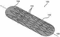
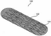
图1是根据本公开的示例实施方案的处于打开的、非卷曲模式(non-crimpedmode)下的增强型支架装置(enhanced stent apparatus)的透视图;1 is a perspective view of an enhanced stent apparatus in an open, non-crimped mode according to an example embodiment of the present disclosure;
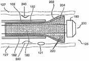
图2是根据本公开的示例实施方案的增强型支架装置的横断面侧视图;2 is a cross-sectional side view of a reinforced stent device according to an example embodiment of the present disclosure;
图3是根据本公开的示例实施方案的在原位处于打开模式下的增强型支架装置的图解;3 is an illustration of a reinforced stent device in situ in an open mode, according to an example embodiment of the present disclosure;
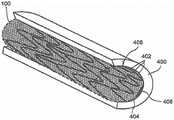
图4是根据本公开的示例实施方案的处于打开模式下的具有多个螺旋盘绕物(multiple helical coil)的增强型支架装置的透视图;4 is a perspective view of a reinforced stent device with multiple helical coils in an open mode according to an example embodiment of the present disclosure;
图5是根据本公开的示例实施方案的处于卷曲的、闭合的模式下的增强型支架装置的透视图;5 is a perspective view of a reinforced stent device in a crimped, closed mode according to an example embodiment of the present disclosure;
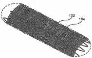
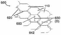
图6a是根据本公开的示例实施方案的处于打开模式下的针织多孔结构(knittedporous structure)的增强型支架装置的透视图;6a is a perspective view of a reinforced stent device of a knitted porous structure in an open mode according to an example embodiment of the present disclosure;
图6b是根据本公开的示例实施方案的针织多孔结构的详细视图;Figure 6b is a detailed view of a knitted porous structure according to an example embodiment of the present disclosure;
图7是根据本公开的示例实施方案的编结多孔结构(braided porous structure)的增强型支架装置的透视图;7 is a perspective view of a reinforced stent device of a braided porous structure according to an example embodiment of the present disclosure;
图8是根据本公开的示例实施方案的设置有纵向不可拉伸的线(wire)和水平可拉伸的弹性体的增强型支架装置的透视图;8 is a perspective view of a reinforced stent device provided with longitudinally non-stretchable wires and horizontally stretchable elastomers in accordance with an example embodiment of the present disclosure;
图9是根据本公开的示例实施方案的增强型支架装置的透视图,其中多孔结构比支撑元件长;9 is a perspective view of a reinforced stent device according to an example embodiment of the present disclosure, wherein the porous structure is longer than the support element;
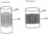
图10是根据本公开的示例实施方案的增强型支架装置的透视图,其中多孔结构在直径上显著大于卷曲的支撑元件,并且自身折叠以便插入到腔中;10 is a perspective view of a reinforced stent device according to an example embodiment of the present disclosure, wherein the porous structure is substantially larger in diameter than the crimped support element and folds upon itself for insertion into the lumen;
图11是根据本公开的示例实施方案的直径显著大于至少部分泄气的球囊的多孔结构的透视图,其中该多孔结构自身被折叠以便插入到腔中;11 is a perspective view of a porous structure of a substantially larger diameter than an at least partially deflated balloon, wherein the porous structure is folded upon itself for insertion into a cavity, according to an example embodiment of the present disclosure;
图12示出了根据本公开的示例实施方案的减小至少多孔结构的直径的漏斗状物(funnel)的用途;Figure 12 illustrates the use of a funnel to reduce at least the diameter of a porous structure according to an example embodiment of the present disclosure;
图13示出了根据本公开的示例实施方案使用可拉伸的橡皮管制造压缩的多孔结构;13 illustrates the use of a stretchable rubber tube to fabricate a compressed cellular structure according to an example embodiment of the present disclosure;
图14是显示根据本公开的示例实施方案的结构的纤维厚度与多孔结构表面积的百分率的曲线图表;14 is a graph showing fiber thickness versus percentage of porous structure surface area for structures according to example embodiments of the present disclosure;
图15是根据本公开的示例实施方案的用于将多孔结构固定于支撑元件的穿入方法(threading method)的详细图解;15 is a detailed illustration of a threading method for securing a porous structure to a support element according to an example embodiment of the present disclosure;
图16是根据本公开的示例实施方案的用于将多孔结构固定于支撑元件的打结方法(knotting method)的详细图解;16 is a detailed illustration of a knotting method for securing a porous structure to a support element according to an example embodiment of the present disclosure;
图17是根据本公开的示例实施方案的显示多孔结构折叠技术的增强型支架装置的横断面图;17 is a cross-sectional view of a reinforced stent device showing a porous structure folding technique according to an example embodiment of the present disclosure;
图18是显示根据本公开的示例实施方案的用于制造多孔结构的方法的示意图;18 is a schematic diagram showing a method for fabricating a porous structure according to an example embodiment of the present disclosure;
图19a是现有技术中典型动脉瘤的图解;Figure 19a is an illustration of a typical aneurysm in the prior art;
图19b是用于治疗动脉瘤的现有技术的图解;Figure 19b is an illustration of the prior art for treating aneurysms;
图19c是根据本公开的示例实施方案的用于治疗动脉瘤的技术的图解;Figure 19c is an illustration of a technique for treating an aneurysm according to an example embodiment of the present disclosure;
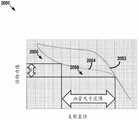
图20是根据本公开的示例实施方案的现有技术支架通过卷曲然后展开的反作用力的图形图解;20 is a graphical illustration of the reaction force through crimping and then unfolding of a prior art stent according to an example embodiment of the present disclosure;
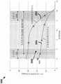
图21是根据本公开的示例实施方案的图1的支架装置通过卷曲然后展开的反作用力的图形图解;21 is a graphical illustration of the reaction force of the stent device of FIG. 1 through crimping and then unwinding, according to an example embodiment of the present disclosure;
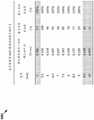
图22是详述根据本公开的示例实施方案的图1的支架装置通过卷曲然后展开的反作用力的表;22 is a table detailing the reaction force of the stent device of FIG. 1 by crimping and then unrolling, according to an example embodiment of the present disclosure;
图23是示出根据本公开的示例实施方案的操作图1的装置的方法的流程图;23 is a flowchart illustrating a method of operating the apparatus of FIG. 1 according to an example embodiment of the present disclosure;
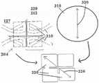
图24是根据本公开的示例实施方案的血管的横断面图;24 is a cross-sectional view of a blood vessel according to an example embodiment of the present disclosure;
图25是根据本公开的示例实施方案的处于收缩状态并且在图24的血管内延伸的图1的支架装置的横断面图;25 is a cross-sectional view of the stent device of FIG. 1 in a collapsed state and extending within the vessel of FIG. 24, according to an example embodiment of the present disclosure;
图26是根据本公开的示例实施方案的处于展开状态并且在图24的血管内延伸的图1的支架装置的横断面图;26 is a cross-sectional view of the stent device of FIG. 1 in a deployed state and extending within the vessel of FIG. 24, according to an example embodiment of the present disclosure;
图27是详述了根据本公开的示例实施方案的与图1的支架组件的一个实施方案的实验测试有关的汇总的身份不明的患者信息的表;27 is a table detailing aggregated unidentified patient information related to experimental testing of one embodiment of the stent assembly of FIG. 1 in accordance with an example embodiment of the present disclosure;
图28a是根据本公开的示例实施方案的处于减小轮廓构造的滑环的横断面图;28a is a cross-sectional view of a slip ring in a reduced profile configuration according to an example embodiment of the present disclosure;
图28b是根据本公开的示例实施方案的处于展开构造的滑环的横断面图;28b is a cross-sectional view of a slip ring in a deployed configuration according to an example embodiment of the present disclosure;
图29是根据本公开的示例实施方案的内皮细胞层在其上覆盖生长(overgrow)的多孔结构的横断面图;29 is a cross-sectional view of a porous structure over which a layer of endothelial cells overgrows according to an example embodiment of the present disclosure;
图30是现有技术情况的图解,其中内皮细胞团从支架支柱上分离;Figure 30 is an illustration of a prior art situation wherein endothelial cell clusters are detached from scaffold struts;
图31a-31d示出了根据本公开的实施方案的自扩张支架的展开;31a-31d illustrate deployment of a self-expanding stent according to embodiments of the present disclosure;
图32-35原位示出了本领域中典型的支架护套材料的原位细节;和Figures 32-35 show in situ details of typical stent sheath materials in the art; and
图36示出了根据本公开的实施方案的针织支架护套的一部分;Figure 36 shows a portion of a knitted stent sheath according to an embodiment of the present disclosure;
图37示出了根据本公开的实施方案的图36的针织支架护套的平面图;37 shows a plan view of the knitted stent sheath of FIG. 36 according to an embodiment of the present disclosure;
图38-39示出了根据本公开的实施方案的包括图36的针织支架护套的材料的细节;和38-39 illustrate details of materials including the knitted stent sheath of FIG. 36 according to embodiments of the present disclosure; and
图40原位示出了根据本公开的实施方案的图9所示的材料的原位细节。FIG. 40 shows in situ details of the material shown in FIG. 9 in accordance with an embodiment of the present disclosure.
示例实施方案的详述DETAILED DESCRIPTION OF EXAMPLE EMBODIMENTS
本公开的各方面通过提供所谓的一体通用式支架组件解决了上述现有技术的缺点。该一体通用式支架组件被配置成适用于各种不同的体腔直径,无论体腔是直的体腔(具有大致一致的直径)还是变化直径的体腔(直径有变化),或者甚至是分支或分叉的体腔。因此,使用一体通用式支架组件消除或减少了尺寸误差,并减少在病人治疗或预防场所(例如医院)需要的手边可用的不同尺寸的支架组件的数量。Aspects of the present disclosure address the above-mentioned disadvantages of the prior art by providing a so-called one-piece universal bracket assembly. The one-piece universal stent assembly is configured to accommodate a wide variety of body lumen diameters, whether the body lumen is a straight body lumen (having a generally uniform diameter), a variable diameter body lumen (variable diameter), or even branched or bifurcated body cavity. Thus, the use of a one-piece universal stent assembly eliminates or reduces dimensional errors and reduces the number of different sized stent assemblies that are readily available in a patient treatment or prophylaxis setting (eg, a hospital).
本申请被划分为多个分类列出部分,这些分类列出部分通常依次包括:装置(例如,多孔结构、支架等)的描述、用于制造装置的材料和方法、药物与该装置的一起使用、以及使用装置的方法。应该理解,各部分标题仅为了清楚,而不意图限制其中描述的主题。此外,在特定部分中所述的主题中的一些可能属于不只一个部分,且因此,一些材料可能会在多个部分之间存在重叠。This application is divided into taxonomic sections that generally include, in order, generally: a description of the device (eg, porous structure, scaffold, etc.), materials and methods for making the device, drugs for use with the device , and a method of using the device. It should be understood that the section headings are for clarity only and are not intended to limit the subject matter described therein. Furthermore, some of the subject matter described in a particular section may belong to more than one section, and as such, some material may overlap between sections.
引言introduction
本公开的各方面通过提供一种支架组件成功地解决了现有技术的缺点,该支架组件被构造成可扩张到直径范围内的任何直径,以提供大约0.33N/mm和大约0.20N/mm之间的持久径向力。Aspects of the present disclosure successfully address the shortcomings of the prior art by providing a stent assembly that is configured to be expandable to any diameter within a range of diameters to provide approximately 0.33 N/mm and approximately 0.20 N/mm persistent radial force between.
根据本公开的一些实施方案,支架组件减少了与选择特定支架组件尺寸相关的风险和误差。According to some embodiments of the present disclosure, stent assemblies reduce the risks and errors associated with selecting a particular stent assembly size.
根据本公开的一些实施方案,支架组件减少了需要留在手边的支架组件的数量。这可以有利地允许较小的医疗机构承担手头上具有用于各种体腔尺寸的支架组件的成本,并且更一般地最小化了手头上具有用于紧急情况的大量库存的不同设备的成本。According to some embodiments of the present disclosure, the stand assembly reduces the number of stand assemblies that need to be kept on hand. This may advantageously allow smaller medical facilities to bear the cost of having stent assemblies on hand for various body cavity sizes, and more generally minimize the cost of having a large inventory of different devices on hand for emergencies.
根据本公开的一些实施方案,支架组件为该范围内的所有直径提供已知的预定径向力预期。According to some embodiments of the present disclosure, the stent assembly provides a known predetermined radial force expectation for all diameters within this range.
根据本公开的一些实施方案,支架组件在植入网(implantation mesh)的长度上提供对体腔(例如血管)的不同直径的更好适应。According to some embodiments of the present disclosure, the stent assembly provides better accommodation for different diameters of body lumens (eg, blood vessels) over the length of the implantation mesh.
根据本公开的一些实施方案,支架组件包括具有低直径的纤维,该纤维允许每个内皮细胞完全覆盖和重叠一根或更多根纤维,从而形成粘附到这些纤维的两侧的组织的内皮细胞层。这样形成的内皮层基本上是稳定的,大大降低了脱离和形成栓塞的趋势,这可以提供改善的患者预后。According to some embodiments of the present disclosure, the scaffold assembly includes fibers with low diameters that allow each endothelial cell to completely cover and overlap one or more fibers, thereby forming an endothelium that adheres to the tissue on either side of the fibers cell layer. The endothelial layer thus formed is substantially stable, greatly reducing the tendency to detach and form emboli, which may provide improved patient outcomes.
根据本公开的一些实施方案,网状纤维包括促进内皮细胞粘附的材料,从而促进内皮层的稳定性。According to some embodiments of the present disclosure, the reticular fibers include a material that promotes endothelial cell adhesion, thereby promoting the stability of the endothelial layer.
根据本公开的一些实施方案,网状物不进行二次处理,例如,用可能减少内皮粘附的化学涂层进行二次处理。此外,没有化学涂层有助于保持低体积纤维(low bulk fibers)和纤维接合(fiber junctions),其中第一纤维在第二纤维之上或之下通过,这是有助于内皮层稳定性的另一个特征。在这样的实施方案中,有可能将一种或更多种药剂灌输到纤维内或支架组件的另一层或另一部分内,以提供这种药剂的益处,同时避免化学涂层的不足。According to some embodiments of the present disclosure, the mesh is not secondary treated, eg, with a chemical coating that may reduce endothelial adhesion. Additionally, the absence of chemical coatings helps maintain low bulk fibers and fiber junctions, where first fibers pass over or under second fibers, which contributes to endothelial layer stability another feature. In such embodiments, it is possible to infuse one or more agents into the fiber or into another layer or portion of the stent assembly to provide the benefits of such agents while avoiding the inadequacies of chemical coatings.
根据本公开的一些实施方案,每个网状纤维与相邻纤维间隔开一段距离,从而最小化单个内皮细胞粘附到多于一根纤维的风险,或防止单个内皮细胞粘附到多于一根纤维,从而减少例如由于血流期间的自然支架脉动导致的内皮细胞从支架摆脱的机会。According to some embodiments of the present disclosure, each reticular fiber is spaced a distance from adjacent fibers, thereby minimizing the risk of a single endothelial cell adhering to more than one fiber, or preventing a single endothelial cell from adhering to more than one fiber root fibers, thereby reducing the chance of endothelial cells escaping from the stent, eg, due to natural stent pulsation during blood flow.
根据本公开的一些实施方案,支架护套可选地包括针织的网。根据本公开的一些实施方案,支架护套网可选地由单根纤维或单组纤维形成。According to some embodiments of the present disclosure, the stent sheath optionally includes a knitted mesh. According to some embodiments of the present disclosure, the stent-sheathing mesh is optionally formed from a single fiber or a single group of fibers.
增强型支架装置的综述Overview of Enhanced Stent Devices
在本公开的一些实施方案中,本公开涉及支架组件,如在PCT专利申请PCT/IB2006/051874中所提出的支架组件,其公开内容在此通过明示引用的方式并入本文。本文公开的方法和套件可以例如使用在该PCT申请中公开的各种支架组件。In some embodiments of the present disclosure, the present disclosure relates to a stent assembly, such as the stent assembly proposed in PCT patent application PCT/IB2006/051874, the disclosure of which is incorporated herein by express reference. The methods and kits disclosed herein can, for example, use the various stent assemblies disclosed in this PCT application.
在本公开的一个示例实施方案中,提供了一种包括多孔结构和任选的下层支撑元件例如支架的装置(其中下层是指多孔结构处在支撑元件和腔壁之间)。In an exemplary embodiment of the present disclosure, a device is provided that includes a porous structure and optionally an underlying support element such as a scaffold (wherein underlying refers to the porous structure between the support element and the cavity wall).
在本公开的一些示例实施方案中,使用包括多孔结构和支架的增强型支架装置来治疗狭窄和/或再狭窄。在本公开的一些示例实施方案中,增强型支架装置提供了超过常规动脉支架的多种益处中的至少一个。例如,增强型支架装置任选用于防止斑块进入血流而引起栓塞,因为多孔结构被制成为具有足够小的孔(尺寸在以下给出),从而将分离的斑块保持在适当的位置。在本公开的一个实施方案中,在支架植入期间,使用多孔结构代替使用栓塞保护设备。任选地,不使用“伞”型栓塞保护设备。任选地,多孔结构与栓塞保护设备联合使用,以便获得优于植入常规动脉支架期间使用栓塞保护设备的方法的增强型保护。在本公开的一个实施方案中,增强型支架装置比常规支架将更广泛的药理学援助递送至治疗区。在本公开的一些实施方案中,增强型支架装置被优化以促进内皮细胞生长和/或迁移。为了清楚起见,多孔结构可以是本文所述的网状支架护套。In some example embodiments of the present disclosure, a reinforced stent device comprising a porous structure and a stent is used to treat stenosis and/or restenosis. In some example embodiments of the present disclosure, reinforced stent devices provide at least one of a variety of benefits over conventional arterial stents. For example, a reinforced stent device is optionally used to prevent plaque from entering the bloodstream and causing embolism because the porous structure is made with sufficiently small pores (dimensions are given below) to hold isolated plaque in place . In one embodiment of the present disclosure, a porous structure is used instead of using an embolic protection device during stent implantation. Optionally, no "umbrella" type embolic protection device is used. Optionally, the porous structure is used in conjunction with an embolic protection device in order to obtain enhanced protection over methods of using an embolic protection device during implantation of conventional arterial stents. In one embodiment of the present disclosure, the reinforced stent device delivers a broader range of pharmacological assistance to the treatment area than conventional stents. In some embodiments of the present disclosure, the reinforced scaffold device is optimized to promote endothelial cell growth and/or migration. For clarity, the porous structure can be a mesh stent sheath as described herein.
图1示出了本公开的一个示例实施方案中的增强型支架组件或支架装置100的透视图。支撑元件102被设计和构造成从增强型支架装置100的中心轴线106以径向方式扩张血管。任选地,支撑元件102在形状上是管形的。在本公开的一些示例实施方案中,支撑元件102由柔性的生物相容性材料构成。任选地,支撑元件102由不锈钢、镍钛诺和/或钴铬合金和/或其他金属合金(例如镁合金)构成。任选地,支撑元件102由生物稳定的或生物可吸收的聚合物构成。在本公开的一些示例实施方案中,支撑元件102是血管支架,例如由

在本公开的一个示例实施方案中,支撑元件102被至少一个多孔结构104覆盖。任选地,支撑元件102用作多孔结构104的支撑结构,例如用于提供径向支撑和/或保持多孔结构104的所需形状。图2显示了增强型支架装置的横断面图。在该实施方案中,支撑元件102为位于支撑元件102外部上的多孔结构104提供结构支撑。In an example embodiment of the present disclosure, the
在本公开的一些示例实施方案中,多孔结构104被放置在支撑元件102的外部上,从而重叠支撑元件102中的间隙(使该设备的孔径尺寸总体上更小,例如150微米),因为常规支架结构通常在杆的结构中产生多个间隙,通常几毫米。在本公开的其他示例实施方案中,多孔结构104仅仅覆盖支撑元件102的一部分。例如,只覆盖支撑元件102的一部分,以避免将腔内流(luminal flow)限制至分支血管。In some example embodiments of the present disclosure, the
在本公开的一些示例实施方案中,多孔结构104延伸超过支撑元件102的至少一个端部。例如,这可以更好地处理处于增强型支架装置100的边缘处的血管的内表面,在该边缘处更容易出现再狭窄。在本公开的示例实施方案中,多孔结构104通过延伸超过支撑元件102的至少一个端部而填补(pad)和/或治疗由支撑元件102的边缘引起的创伤。任选地,多孔结构104延伸超过支撑元件102的端部不超过1mm。任选地,多孔结构104延伸超过支撑元件102的端部超过1mm。任选地,多孔结构104延伸超过支撑元件102的仅一个端部或两个端部(如图9所示)。In some example embodiments of the present disclosure, the
在本公开的一些示例实施方案中,将多孔结构104附接到支撑元件102,以防止多孔结构104解开和/或引起组织刺激和/或避免多孔结构在展开期间从支撑元件脱离。任选地,将多孔结构104的端部折叠在支撑元件102的端部上并附接,从而为有可能引起创伤的边缘提供了衬垫。任选地,多孔结构104的端部自身折叠并且由于支撑元件和腔之间的压力而保持折叠。在本公开的一个实施方案中,使用处理(如加热)来使该折叠明晰(sharp)和/或永久。In some example embodiments of the present disclosure, the
应理解,虽然在图1和图2中示出了增强型支架装置的示例构造,但也可以使用其他构造,所述其他构造包括:在药物洗脱支撑元件上的多孔结构104;在支撑元件102上的药物洗脱多孔结构;在药物洗脱支撑元件上的药物洗脱多孔结构;在至少两个多孔结构(任选地,一些或全部洗脱药物)之间的支撑元件;以及包括多个层的增强型支架,所述多个层表现出不同的可选特性,如降解时间和/或药物洗脱。应理解,以上构造中任一个包括可生物降解的和/或生物可吸收的材料。任选地,针对患者的病状所指示的具体治疗方案来选择构造。It should be understood that while an example configuration of a reinforced stent device is shown in FIGS. 1 and 2, other configurations may be used, including:
在本公开的一些示例实施方案中,多孔结构104用于控制由增强型支架装置施加给体腔壁的局部压力。例如,在多孔结构至少部分地覆盖支架时,通过增加或减少多孔结构的覆盖面积,可以改变每单位面积由增强型支架装置施加的压力。在本公开的一些实施方案中,覆盖面积的修改需要考虑的因素诸如支撑元件102的刚度和支撑元件120的支撑支柱的几何结构和/或覆盖面积。在本公开的一个实施方案中,使用压力控制来减小增强型支架装置引起斑块进而从腔壁脱落的可能性。在本公开的一些实施方案中,使用压力控制来减小通常由支架植入物引起的组织创伤,从而增强了对狭窄/再狭窄的防护。此外,在本公开的一些实施方案中,以前的由于可能会创伤腔组织而不能使用的支撑元件102支柱可以任选地与多孔结构104结合使用。In some example embodiments of the present disclosure, the
在本公开的一些示例实施方案中,使用如本文所述的至少一个多孔结构来治疗胆管。例如,胆管常常由于限制流动的碎片(例如胆固醇)而堵塞。使用增强型支架装置治疗胆管可以增加胆管的直径,改善胆管的运作。In some example embodiments of the present disclosure, the bile duct is treated using at least one porous structure as described herein. For example, bile ducts are often blocked by debris that restricts flow, such as cholesterol. Treating the bile duct with an enhanced stent device can increase the diameter of the bile duct and improve its functioning.
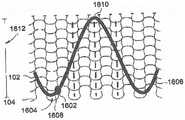
已知的是,不同类型的体腔具有不同的表面纹理(surface texture)(两种体腔彼此不同),并且有时在一种类型的腔内有不同的表面纹理。因此,在本公开的一些示例实施方案中,根据正被治疗的腔的内部表面纹理来制造和/或使用具有不同表面纹理构造的不同的多孔结构。例如,体腔中的峰和谷与多孔结构的反峰(counter peak)和反谷配合(即,多孔结构的反峰进入腔谷中,且多孔结构的反谷接受腔峰)。任选地,反峰和反谷具有与正被治疗的腔中存在的峰和谷相同的幅度。It is known that different types of body cavities have different surface textures (two types of body cavities are different from each other), and sometimes different surface textures within one type of cavity. Accordingly, in some example embodiments of the present disclosure, different porous structures with different surface texture configurations are fabricated and/or used according to the interior surface texture of the cavity being treated. For example, peaks and valleys in a body cavity cooperate with counter peaks and inverse valleys of the porous structure (ie, the counter peaks of the porous structure enter the cavity valleys, and the counter valleys of the porous structure accept the cavity peaks). Optionally, the inverse peaks and inverse valleys have the same amplitude as the peaks and valleys present in the lumen being treated.
应理解,孔径尺寸、多孔结构厚度、纤维厚度(或French)和/或覆盖面积随应用不同而不同。例如,在治疗颈动脉时,应防止超过100微米的碎片到达大脑,因此多孔结构被设计成使得在支架扩张至通常约8毫米时,大多数孔径尺寸小于100微米。作为另一个例子,当治疗冠状动脉时,较大的碎片(>100微米)是不成问题的,而内皮化过程(endotheliazationprocess)和向侧支流动不受限制(non-restriction of flow to side branches)是更为重要的。因此,对于冠状动脉应用,当支撑元件102处于扩张位置(通常直径约3mm)时,多孔结构中的孔任选地大于100微米且低于300微米。在本公开的一些实施方案中,多孔结构在内皮细胞上生长的速率可以通过增加和/或减小纤维厚度和多孔结构厚度来调节。It should be understood that the pore size, porous structure thickness, fiber thickness (or French) and/or coverage area will vary from application to application. For example, when treating carotid arteries, debris larger than 100 microns should be prevented from reaching the brain, so the porous structure is designed such that when the stent is expanded to typically about 8 mm, most of the pore sizes are smaller than 100 microns. As another example, when treating coronary arteries, larger fragments (>100 microns) are not a problem, while the endothelialization process and flow to side branches are not restricted (non-restriction of flow to side branches) is more important. Thus, for coronary applications, the pores in the porous structure are optionally larger than 100 microns and below 300 microns when the
在本公开的一个示例实施方案中,多孔结构104的厚度在100微米以下。在本公开的一些示例实施方案中,多孔结构的厚度小于30微米。任选地,多孔结构的厚度小于10微米。例如,多孔结构的厚度小于5微米或1微米。任选地,多孔结构104包括至少一种细的、线状的纤维。在本公开的一些示例实施方案中,多孔结构104包括至少一种厚度为40nm到40微米的纤维。任选地,纤维厚度类似于或小于内皮细胞的直径,以促进内皮细胞在纤维之间和/或在至少一种纤维周围生长。在本公开的一个示例实施方案中,使用超强力纤维(super-fiber)来构造多孔结构104,其中超强力纤维由编织在一起的多根纤维制成。任选地,超强力纤维用于提高多孔结构104的强度。In an example embodiment of the present disclosure, the thickness of the
在本公开的一个示例实施方案中,将多孔结构104的纤维纺丝(spun)和/或针织和/或编织(woven)和/或编结,以便为多孔结构104提供结构和在多孔结构104中提供孔110。任选地,该多孔结构被编织成均匀的图案。任选地,多孔结构被构造成使得纤维任意地位于多孔结构104中。任选地,使用聚合物纤维来构造多孔结构104。任选地,将聚合物覆盖物应用于多孔结构104和/或支撑元件102。示例的多孔结构制造在以下“制造方法”部分中更详细地描述。In an exemplary embodiment of the present disclosure, the fibers of the
在本公开的一个示例实施方案中,聚合物覆盖的多孔结构104任选地由闭合联锁设计和/或开放联锁设计或类似于典型支撑元件102设计的半开放设计来制成。开放联锁设计在需要侧分支(side branching)时是有利的。当治疗两根血管的接合处时,有时需要通过另一根血管的侧部引入一个支架。开放联锁设计允许这种过程,且当多孔结构由金属网制成时,开放联锁设计被使用,以便允许容易的侧分支支架。任选地,在不可生物降解的支撑元件102上使用可生物降解的聚合物涂层将在可生物降解的聚合物降解之后,留下包埋(embed)的支撑元件102。In an exemplary embodiment of the present disclosure, the polymer covered
在本公开的一个示例实施方案中,将多孔结构104卷曲成小的直径,同时仍然保持它的柔性,以便能够成功地操纵穿过患者的血管到达待植入增强型支架装置100的部位。在本公开的一个示例实施方案中,多孔结构104是可扩张的,以使得多孔结构104在患者的血管内的治疗部位处展开时能够与支撑元件102一起扩张。任选地,多孔结构104沿着纵轴的扩张与支撑元件102沿着纵轴的扩张相匹配。In an example embodiment of the present disclosure, the
在本公开的一个示例实施方案中,至少多孔结构104是可扩张的,而不显著缩短或伸长多孔结构104的长度。例如,在一些实施方案中,至少多孔结构104是可扩张的,具有小于约20%的缩短、小于约%15的缩短、小于约10%的缩短、或小于约6%的缩短、或约6%的缩短。通常,缩短的百分率定义为100x(长度变化÷装载长度或最终长度)。任选地,多孔结构104的扩张不同于支撑元件102,例如使用本文所述的滑动连接。如本文的其它地方所述,在多孔结构104的针织实施方案中,扩张的发生至少部分是由于针织结构导致的,而不一定是因为在构造多孔结构104中使用的纤维的弹性导致。在本公开的一个实施方案中,包括多孔结构104的至少一种纤维在制造期间设置成具有松弛度(slack),以便在多孔结构104扩张时提供附加的纤维材料。图8显示了增强型支架装置900的透视图。根据本公开的一个示例实施方案,增强型支架装置900设置有不可拉伸的线902和可拉伸的弹性体纤维904。这种实施方案有助于保持整个装置900的长度,同时允许在植入期间的可扩张性和柔性。In an exemplary embodiment of the present disclosure, at least the
在本公开的一个示例实施方案中,提供了增强型支架装置,其包括至少一个可扩张的支撑元件和可扩张的多孔结构。支撑元件任选地是支架,其示例在用于为各种体腔提供治疗的领域中是已知的。在本公开的一个实施方案中,多孔结构具有类似于渔网的结构。在本公开的一个实施方案中,多孔结构由直径约15-20微米的纤维针织而成,具有小于20%的覆盖面积并且具有约150×200微米的孔径尺寸。在本公开的一些实施方案中,多孔结构通过缝合(stitching)来至少暂时地附接于支撑元件的支撑支柱。任选地,针脚(stitches)是松弛的,以允许多孔结构在支撑支柱上滑动,例如提供本文关于图15所述的额外的可扩张性。在本公开的一些实施方案中,缝线是可生物降解的。在本公开的一些实施方案中,支撑元件和/或多孔结构适合于将药剂洗脱进入正被治疗的体腔中。In an example embodiment of the present disclosure, a reinforced stent device is provided that includes at least one expandable support element and an expandable porous structure. The support element is optionally a stent, examples of which are known in the art for providing therapy to various body cavities. In one embodiment of the present disclosure, the porous structure has a structure similar to a fishing net. In one embodiment of the present disclosure, the porous structure is knitted from fibers of about 15-20 microns in diameter, has a coverage area of less than 20% and has a pore size of about 150 x 200 microns. In some embodiments of the present disclosure, the porous structure is at least temporarily attached to the support struts of the support element by stitching. Optionally, the stitches are slack to allow the porous structure to slide over the support struts, eg, to provide additional expandability as described herein with respect to FIG. 15 . In some embodiments of the present disclosure, the suture is biodegradable. In some embodiments of the present disclosure, the support element and/or porous structure are adapted to elute the agent into the body cavity being treated.
在本公开的一些实施方案中,根据预期用途或待实施的治疗来选择增强型支架装置的不同的特征。例如,任选地,根据对预防某一尺寸的碎片提供栓塞倾泻(embolicshower)保护的需要来选择孔径尺寸。作为另一个示例,任选地选择覆盖面积,以修改正被治疗的腔上的局部压力。这些特征中的许多特征是相互关联的,例如,如本文所描述和如图14中所显示的。In some embodiments of the present disclosure, various features of the reinforced stent device are selected according to the intended use or treatment to be performed. For example, the aperture size is optionally selected according to the need to provide embolic shower protection against fragments of a certain size. As another example, the coverage area is optionally selected to modify the local pressure on the lumen being treated. Many of these features are interrelated, eg, as described herein and shown in FIG. 14 .
在本公开的一个实施方案中,多孔结构104是柔性的,以允许腔自然地改变其直径,以引起腔中的压力改变和/或对肌肉活动响应。在本公开的一些实施方案中,多孔结构104分为多个半独立区部,这些区部对腔内的刺激或来自腔的刺激反应不同。任选地,使用多个区部来防止腔在多孔结构104的整个长度上结合(band)。In one embodiment of the present disclosure, the
多孔结构的示例特性和性能Example Properties and Properties of Porous Structures
在本公开的一个实施方案中,将在下面更详细描述的制造技术(例如为多孔结构104的单个纤维或部分提供了松弛的针织)使得多孔结构104在展开时能够任选地扩张至高达其在插入时的直径的10倍(插入直径在下面更详细地描述)。例如,在冠状动脉应用中,多孔结构104可以从直径1mm扩张至3mm。在其他示例中,多孔结构104在颈动脉应用中可以从2mm扩张至8mm,而在大脑应用中,多孔结构104可以从0.3mm扩张至2.5mm。这些数值是近似的,且仅仅用于举例说明。在本公开的一个实施方案中,多孔结构104的扩张用以下三种方式中的至少一种来实现:1)多孔结构104的针织/编结/编织结构(包括纤维松弛和卷曲纤维);2)制备多孔结构104的纤维是至少轻微弹性的;3)多孔结构104和支撑元件102之间的滑动连接(下文描述)允许多孔结构104在扩张期间相对于支撑元件102在一定限度内移位。在本公开的一个实施方案中,制备多孔结构104的纤维包括从约2%至约80%的非弹性材料。在本公开的一些实施方案中,制备多孔结构104的纤维的弹性材料允许扩张至其初始尺寸的高达1000%。In one embodiment of the present disclosure, fabrication techniques (eg, providing a relaxed knit for individual fibers or portions of the porous structure 104), which will be described in more detail below, enable the
在本公开的一些示例实施方案中,多孔结构104在经受扭转、转动、压缩和/或伸长时显示了高的耐久性,这允许多孔结构104能够承受得住穿过患者的脉管系统到达治疗部位的递送过程。在本公开的一个实施方案中,多孔结构104可在若干个位置处松弛地附接至支撑元件102,并且折叠,以便插入到腔中。折叠的多孔结构104提供了直径减小的装置,以便更容易插入到患者的体腔中。In some example embodiments of the present disclosure, the
在本公开的一些示例实施方案中,多孔结构104的总面积的20%包括处于扩张构造时具有不大于50微米、200微米或超过200微米的近似直径的孔。应认识到,在制造多孔结构(例如,用某些制造技术来制造,如静电纺丝(electrospinning)和/或针织)的过程期间,在多孔结构内产生的孔可以重叠。该重叠有效地产生了小于规定值的孔径尺寸。然而,在本公开的一些示例实施方案中,有效的标称孔径尺寸在直径上不大于50微米、200微米或者超过200微米。在本公开的一些实施方案中,孔径尺寸被选择为促进内皮细胞以一定的速率覆盖生长。In some example embodiments of the present disclosure, 20% of the total area of the
应该注意的是,由于多孔结构104的制造和/或所需性能,至少某种程度上,孔的形状可能改变。例如,在针织多孔结构中,孔最可能是大致正方形的。相反,使用编织技术制造多孔结构可能产生方形和/或矩形的孔,而编结的多孔结构可能呈现四边形的孔,如图7所示。在描述孔的近似“直径”时,应该认识到,全部的孔、一些孔或没有孔将是能够使用直径进行简单面积测量的实际的圆形、方形、矩形和/或四边形。因此,使用直径描述仅仅是一种表达示例孔径尺寸的近似方法。例如,“直径”可以是在四边形(如正方形或矩形)的两个平行边之间的距离。It should be noted that the shape of the pores may vary, at least to some extent, due to the fabrication and/or desired properties of the
在下面描述的一些部分中,本文所述的孔径尺寸是参考其在多孔结构在腔中展开时的尺寸。在其他部分中,该尺寸是指在卷曲时的孔径尺寸。有时,本文所述的孔径尺寸是指处于介于卷曲构造和展开构造之间的状态下的其尺寸。在上下文中,应该容易看出以上哪一种构造适用,然而,在不清楚的情况下,孔径尺寸可以被认为是适用于扩张构造、卷曲构造或中间构造。当提到纤维直径时,它涉及用于构造多孔结构104的纤维。例如,如果多孔结构104由包括一束各自直径为2微米的10根纤维的超强力纤维构造成时,总的超强力纤维直径为约20微米。此外,应理解,对纤维直径的参考是近似值且仅仅为了方便,而并不意味着该纤维必定是圆形的。任选地,纤维尺寸按French尺度计量,例如0.003Fr。In some parts of the description below, the pore size dimensions described herein are with reference to the dimensions of the porous structure as it unfolds in the cavity. In other sections, the size refers to the aperture size when crimped. Occasionally, the aperture size described herein refers to its size in a state intermediate between a crimped configuration and an expanded configuration. In context, it should be easy to see which of the above configurations applies, however, where it is unclear, the aperture size may be considered to apply to the expanded configuration, the crimped configuration or the intermediate configuration. When referring to fiber diameter, it refers to the fibers used to construct the
参考图14,示出了关于具有渔网型构造的多孔结构的多孔结构的纤维厚度与支撑元件的覆盖面积的百分率的相互关系的曲线图表1500。可看出,总的趋势是,随着纤维尺寸变得更薄,专属于结构的多孔结构表面积的量减少。在本公开的一个实施方案中,希望具有25%以下的覆盖面积。任选地,多孔结构104显示了低于20%的覆盖面积。在本公开的一个实施方案中,多孔结构的覆盖面积适于被最小化,同时还执行预期的腔治疗功能,例如本文所述的那些功能。在本公开的一些实施方案中,多孔结构104的覆盖面积被最小化,以便避免不希望的临床副作用。例如,腔组织刺激和热原效应是最小化多孔结构104的覆盖面积以及任选地其他特征(如孔径尺寸、多孔结构厚度和/或纤维厚度)的考虑因素。Referring to FIG. 14, a
在本公开的一些示例实施方案中,多孔结构104的结构与孔的比例、纤维尺寸和/或孔被设定尺寸以便允许容易通过多孔结构104扩散和促进内皮细胞的生长。因为用于构造多孔结构104的纤维2202的直径大约是内皮细胞2204的尺寸或者更小,如图29所示,所以在多孔结构上生长的细胞的完整性将好于在现有技术中获得的完整性。单个细胞在统计学上将具有与血管壁的牢固连接,因为它的尺寸与纤维直径大致相同或者更大,因此,在本公开的一个实施方案中,将其自身在多于一个位置锚固到其天然基底内膜层(nativebasalamina intimal layer),并能够获得更好的生长条件。因此可预期,与目前使用药物洗脱支架进行治疗时所实现的相比,迟发或亚急性血栓形成的机会可以降低。另外,多孔结构104有效用作血栓倾泻保护设备、将分离的斑块保持在适当的位置、防止斑块从血管壁进入血流。应该指出,考虑到纤维厚度、多孔结构厚度和/或孔径尺寸,多孔结构104被构造成使得内皮细胞将在多孔结构104和任选的支撑元件102上覆盖生长,以便将增强型支架固定在适当的位置和/或将支撑元件102和/或多孔结构104的外来材料与血流隔离。在本公开的一个示例实施方案中,在植入数小时内建立内皮细胞层在多孔结构104上的覆盖生长。在本公开的一个实施方案中,由于多孔结构104的与内皮细胞相关的特性(例如,总厚度与单个内皮细胞大致相同或者小于单个内皮细胞),因此覆盖生长在该时间范围内完成。在本公开的一些实施方案中,设想的是,由于使用增强型支架装置的内皮化速度的结果,可减少患者在支架植入手术后的平均住院时间。另外,由于在增强型支架装置100的至少多孔结构104上的快速内皮化的结果,预期药物治疗的速度和效力可得到提高。In some example embodiments of the present disclosure, the structure to pore ratio, fiber size, and/or pores of the
图30示出了使用现有技术药物洗脱支架的缺点,其中内皮细胞的团块已从支架支柱2304上分离,露出了支架的暴露“岛状物(island)”2302。有时,由于内皮细胞与支柱2304的聚合物涂层的粘附不良,团块从支柱2304掉落。导致这种不良粘附的原因是,支架支柱2304通常比单一内皮细胞大一个数量级,从而需要产生大的内皮细胞桥来跨越该支柱。暴露的岛2302可能会成为血栓产生(thrombosis develpoement)的种子。在本公开的一些实施方案中,多孔结构104被构造成减小内皮细胞从多孔结构上掉落的可能性,从而减小迟发或亚急性血栓形成的产生和支撑元件102暴露于腔内的物质的机会。例如,任选地通过用一定厚度的至少一种纤维来构造多孔结构104以及利用孔径尺寸(以便允许内皮细胞穿过该孔生长)来促进内皮细胞滞留,例如本文所述的。任选地,通过使用一定厚度的纤维层例如本文所述的那些来促使内皮细胞保留在多孔结构上。任选地,如图29所示的单一纤维多孔结构104的线性性质能减小内皮细胞的大的团块变得移离的可能性。在本公开的一个实施方案中,将多孔结构104(任选地,浸透有药物的多孔结构104)放置在裸金属或药物洗脱支撑元件的内部,以便减小支撑元件的致血栓性(thrombogenicity),例如,通过促进内皮细胞在其上生长和/或通过覆盖支撑元件的一部分来减小支撑元件的暴露表面积。Figure 30 illustrates the disadvantage of using prior art drug eluting stents, where clumps of endothelial cells have detached from stent struts 2304, exposing exposed "islands" 2302 of the stent. Occasionally, clumps fall off the
如以上所建议的,使用厚度类似于或小于内皮细胞直径的薄纤维,能够使内皮细胞层在多孔结构104上生长,同时至少在内皮细胞的两个点处仍然紧密地约束到基底内膜层(basal intima layer),在多孔结构104的每一侧各有一个点。在本公开的一个实施方案中,该基底内膜层在内皮细胞层上的锚固效应减小了内皮细胞层的部分脱落和进入腔的机会。这有效地减小了患者栓塞的机会和/或还减小了异物(例如支架和多孔结构)与正被治疗的腔的内含物接触和反应的可能性。如果几个内皮细胞的团块从多孔结构104上掉落进而暴露出一片纤维,相信对患者伤害的机会会减小,这是因为线性的、单一的内皮细胞宽度几何形状不像图30中所示的那样具有致血栓性,在图30中,直径为至少几个细胞的直径的内皮细胞团块已经掉落。另外,在暴露的多孔结构104上的再内皮化将比在暴露的支柱2304上更快,至少因为以下原因:在多孔结构104的情况下,当刚好一个内皮细胞在用于构造多孔结构的内皮细胞尺寸的纤维上覆盖生长时,形成了内皮细胞层。相反,内皮细胞层覆盖生长只有在多个内皮细胞已经覆盖暴露的岛之后才完成。As suggested above, the use of thin fibers with a thickness similar to or less than the diameter of the endothelial cells enables the endothelial cell layer to grow on the
在本公开的一个实施方案中,通过将多孔结构104用于药物洗脱减小迟发或亚急性血栓形成的风险任选地允许减少患者使用抗凝血剂的持续时间和/或剂量。In one embodiment of the present disclosure, reducing the risk of late or subacute thrombosis by using the
在本公开的一些示例实施方案中,纤维厚度、多孔结构厚度和/或孔径尺寸全部根据多孔结构104的应用和患者的需要来单独地改变。例如,在冠状动脉中,这有助于提供良好的药物分散。在这种示例中,包括多孔结构104的纤维任选地定位成更加靠近在一起,以便允许将药物更完全输送给患者。In some example embodiments of the present disclosure, the fiber thickness, porous structure thickness, and/or pore size are all individually varied according to the application of the
在一些示例实施方案中,当大分子药物(其向组织中扩散的能力很差)用于抵抗再狭窄时,多孔结构可以用适当的药物浸泡和/或浸透,以便使药物更好地扩散。由于副作用和过度毒性,所使用的大多数药物的最大浓度是相当有限的,且同时,为了在没有支架支柱覆盖的区域中允许具有最佳的药物代谢动力学,该浓度是不足够的。具有对支架区域的更好的几何覆盖的多孔结构网为由支架所覆盖的整个区域提供了更好和更佳的药物代谢动力学。例如,当使用高的道尔顿大分子药物时,或者当脂质体是治疗剂的载体时,或者当药物的立体化学结构是大的和/或复杂的时,和/或当药物是疏水性的时,较为均匀的药物分布是非常理想的。在本公开的一些示例实施方案中,药物代谢动力学也得到优化,因为药物位于多孔结构104的纤维上/纤维中,并且被覆盖和密封在内皮层中,这有助于防止药物被血液冲走。In some example embodiments, when a macromolecular drug (which has a poor ability to diffuse into tissue) is used to resist restenosis, the porous structure can be soaked and/or saturated with an appropriate drug to allow better drug diffusion. The maximum concentration of most drugs used is rather limited due to side effects and excessive toxicity, and at the same time is not sufficient to allow for optimal pharmacokinetics in areas not covered by stent struts. Porous mesh with better geometric coverage of the scaffold area provides better and better pharmacokinetics for the entire area covered by the scaffold. For example, when high Dalton macromolecular drugs are used, or when liposomes are carriers for therapeutic agents, or when the stereochemical structure of the drug is large and/or complex, and/or when the drug is hydrophobic When sexual, a more uniform drug distribution is ideal. In some example embodiments of the present disclosure, pharmacokinetics are also optimized because the drug is located on/in the fibers of the
在本公开的一些示例实施方案中,例如在旁路静脉移植中,侧分支是不成问题的,因此任选地使孔径尺寸更小,但不至于小到防止内皮细胞穿过其生长。在本公开的另一个示例实施方案中,例如在颈动脉中,侧分支一般不被认为是一个问题,但捕获碎片是个问题。因此,在本公开的一些示例实施方案中,多孔结构104的孔径尺寸被减小至直径小到20微米。在其他应用中,孔径尺寸可以增加至50微米、100微米、200微米或甚至超过200微米,这取决于增强型支架装置100的应用。In some exemplary embodiments of the present disclosure, such as in bypass vein grafts, side branches are not a problem, so the pore size is optionally made smaller, but not so small as to prevent endothelial cells from growing therethrough. In another example embodiment of the present disclosure, such as in the carotid artery, side branches are generally not considered a problem, but capturing debris is. Accordingly, in some example embodiments of the present disclosure, the pore size of the
在本公开的一些示例实施方案中,使用多个多孔结构。任选地,至少一个多孔结构在支撑元件102的腔内位于支撑元件102的内部面上。任选地,多于一个多孔结构位于支撑元件102的外表面上。在本公开的一些示例实施方案中,位于支撑元件102上的至少一些多孔结构被构造成是“同相的(in-phase)”,其中多孔结构的孔彼此重合。任选地,多孔结构是“不同相的(out-phase)”,其中孔被构造成彼此不重合。在本公开的一个示例实施方案中,使用“不同相的”构造来改进多孔结构和腔内表面之间的接触表面积。在本公开的一个实施方案中,增加的接触表面积可以改进药物代谢动力学、减小由多孔结构104施加于腔壁上的局部压力、改进栓塞倾泻保护和/或实现其他有利效果。在本公开的一些示例实施方案中,多孔结构104被构造为呈与支撑元件102相同的形状和图案,但比例较小。In some example embodiments of the present disclosure, multiple porous structures are used. Optionally, at least one porous structure is located on the interior face of the
示例制造材料Example Manufacturing Materials
应该指出的是,在本公开的一些示例实施方案中,需要可拉伸的和/或可扩张的多孔结构104。因此,在本公开的一些实施方案中,选择的材料为:a)可拉伸的;和/或b)可用于制造可拉伸的多孔结构(例如针织结构)。在本公开的一些示例实施方案中,使用可生物降解的(即可由身体分解的)和/或生物可吸收的(即可吸收到身体中的)材料。另外,根据本公开的一些实施方案,使用材料的混合物。在本公开的一个实施方案中,选择一种材料是因为它虽然薄,但在制造、展开和/或使用期间表现出耐久性。在本公开的一个实施方案中,待使用的材料的其它考虑因素是它们的生物相容性、毒性、血液相容性和致血栓性。It should be noted that in some example embodiments of the present disclosure, a stretchable and/or expandable
用于制造多孔结构104的示例材料包括基于天然的材料,例如改性纤维素和/或胶原。在本公开的一些实施方案中,使用金属纤维来构造多孔结构,多孔结构任选地由不锈钢和/或CoCr和/或CoNi合金以及其他可能的材料来构造。任选地,所使用的金属纤维被涂覆有至少一种聚合物。在本公开的一些实施方案中,多孔结构由形状记忆合金例如镍钛诺制造。任选地,将碳纤维加入到多孔结构104中,以便改进多孔结构104的强度特征。任选地,将玻璃纤维加入到多孔结构104中,以便改进多孔结构104的强度特征。任选地,将耐久的、可吸收的和/或可降解的纤维加入到多孔结构104中,以便改进纤维在制造期间的强度和耐久特征,所述纤维被降解或吸收或冲走,从而留下更薄的多孔结构104。Exemplary materials for fabricating the
在本公开的一个实施方案中,一些聚合物纤维由于它们是弹性的、生物相容的、血液相容的、可制成不粘于内皮组织、可选择性地是生物稳定的和/或可生物降解的、表现了所需的机械强度、是可灭菌的、具有高温转化区(在37℃下为固体且不粘)、能够容纳有效量的药物、和/或可以以控制速率释放包埋的药物,而被选择用于构造多孔结构104。在本公开的一些示例实施方案中,表现出这些性能中的一些或全部的其他材料任选地被用来构造多孔结构104。任选地,在多孔结构104上设置涂层,该涂层包括表现出这些性能中的一些或全部的材料。In one embodiment of the present disclosure, some polymeric fibers can be made non-stick to endothelial tissue, optionally biostable, and/or can be made because they are elastic, biocompatible, blood compatible, Biodegradable, exhibits the required mechanical strength, is sterilizable, has a high temperature transition zone (solid and non-stick at 37°C), can hold an effective amount of drug, and/or can release the package at a controlled rate The buried drug is selected for constructing the
聚合物纤维任选地由以下材料中的任一种制成:热塑性聚合物,例如聚对苯二甲酸乙二醇酯(PET)、聚烯烃、氧化丙烯酸类、PTFE、聚乙烯-醋酸乙烯酯(polyethylene co-vinyl acetate)、聚乙烯弹性体、PEO-PBT、PEO-PLA、PBMA、聚氨基甲酸酯、Carbosil(PTG产品)、医用等级的聚碳酸酯氨基甲酸乙酯、尼龙、PEEK-Optima、羧酸部分(包括聚丙烯酸、聚甲基丙烯酸、马来酸、己糖酸(helonic acid)、衣康酸(taconic acid)和/或这些单体的组合和/或这些单体的酯中的一种或多种)、热塑性聚合物、热固性聚合物(thermoseticpolymer)、聚烯烃弹性体、聚酯、聚氨基甲酸酯、聚氟代聚合物(polyfluoropolymer)和/或尼龙。任选地,纤维由弹性体构成。任选地,纤维由涂覆有药物和聚合物涂层的纤维构成,药物和聚合物涂层涂覆在金属上和/或聚合物纤维上、被混合以获得预定的药物释放特征。任选地,纤维由除了以上列举的示例材料以外的其他材料构成。任选用于该目的的示例聚合物由


在本公开的一些实施方案中,多孔结构由可吸收/可降解的聚合物制成,例如聚乳酸-共聚-聚乙醇酸(“PLGA”)共聚物或者任何其他可降解的共聚物组合,例如聚己内酯(“PCL”)、聚葡萄糖酸酯(polygluconate)、聚乳酸-聚氧化乙烯共聚物、聚羟基丁酸酯、聚酸酐、聚磷酸酯、聚氨基酸、聚-L-丙交酯、聚-D-丙交酯、聚乙交酯、聚α-羟基酸及其组合。In some embodiments of the present disclosure, the porous structure is made of an absorbable/degradable polymer such as polylactic-co-polyglycolic acid ("PLGA") copolymer or any other degradable copolymer combination such as Polycaprolactone ("PCL"), polygluconate, polylactic acid-polyethylene oxide copolymer, polyhydroxybutyrate, polyanhydride, polyphosphate, polyamino acid, poly-L-lactide , poly-D-lactide, polyglycolide, polyalpha-hydroxy acid, and combinations thereof.
示例制造方法Example Manufacturing Method
本文所述的许多方法和定向被设计成提供表现至少一些可扩张性质的多孔结构。多孔结构104任选地被调节和构造成当它在正被治疗的腔内展开时拉伸。在本公开的一些示例实施方案中,多孔结构104设置有可拉伸性,以便容易将多孔结构104相对于支撑元件102或另一中间层(例如移植物或缓冲元件)定位。Many of the methods and orientations described herein are designed to provide porous structures that exhibit at least some expandable properties.
在本公开的一个示例实施方案中,由于交织和/或卷曲和/或纹理化的纤维的结构(卷曲、松弛),编织、编结和/或针织产生了所获得的多孔结构的一些或全部弹性。这可以通过将多孔结构固定到支架的材料伸长性能来实现。在本公开的一些示例实施方案中,多孔结构通过组合几种交织技术(例如,在编结的多孔结构上针织或者在针织的多孔结构上编结)来制备。在本公开的一些实施方案中,使用这些技术来组合和/或产生多个层。在本公开的一些示例实施方案中,使用具有“嵌入(laid in)”纱的经纱针织多孔结构。在本公开的一些示例实施方案中,使用弹性体的或卷曲的纬纱来编织多孔结构,以获得径向弹性。In an exemplary embodiment of the present disclosure, braiding, braiding, and/or knitting imparts some or all of the elasticity of the resulting porous structure due to the structure (crimping, slack) of the interwoven and/or crimped and/or textured fibers . This can be achieved by securing the porous structure to the material elongation properties of the scaffold. In some example embodiments of the present disclosure, the porous structure is prepared by combining several interlacing techniques (eg, knitting on a knitted porous structure or knitting on a knitted porous structure). In some embodiments of the present disclosure, multiple layers are combined and/or created using these techniques. In some example embodiments of the present disclosure, the porous structure is knitted using warp yarns having "laid in" yarns. In some example embodiments of the present disclosure, the porous structure is woven using elastomeric or crimped weft yarns to achieve radial elasticity.
在本公开的一些示例实施方案中,多孔结构通过组合几种技术来制造,例如在编织的多孔结构上针织或者在针织的多孔结构上编织。在本公开的一些示例实施方案中,使用具有“嵌入”纱的纬纱针织多孔结构。在本公开的一些示例实施方案中,使用弹性体的和/或卷曲的纬纱来编织多孔结构,以获得径向弹性。任选地,多孔结构包括定向为大致平行于支撑元件的纵轴的至少一种纤维。In some example embodiments of the present disclosure, the porous structure is fabricated by combining several techniques, such as knitting on a woven porous structure or weaving on a knitted porous structure. In some example embodiments of the present disclosure, the porous structure is knitted using weft yarns with "embedded" yarns. In some example embodiments of the present disclosure, the porous structure is woven using elastomeric and/or crimped weft yarns to achieve radial elasticity. Optionally, the porous structure includes at least one fiber oriented generally parallel to the longitudinal axis of the support element.
在本公开的一个示例实施方案中,将所制造的多孔结构作为覆盖物添加到支撑元件102。任选地,多孔结构104与支撑元件102分开使用,支撑元件102任选地不用于支架植入。在本公开的一些示例实施方案中,多孔结构104直接制造到支撑元件102上。In an example embodiment of the present disclosure, the fabricated porous structure is added to the
在本公开的一个示例实施方案中,多孔结构104通过针织领域技术人员公知的用于非相似领域(如制衣和纺织品)的针织技术来制造。多孔结构104的针织任选地通过具有20个和35个之间的针的头部(head)进行。任选地,所使用的头部具有30个和45个之间的针。任选地,所使用的头部具有35个和80个之间的针。头部尺寸对多孔结构的影响的一个示例可以在上述图14中见到,图14中绘制了22尺寸的头部和35尺寸的头部。在图14中,针的规格为40。In an example embodiment of the present disclosure, the
在本公开的一些实施方案中,针织物的形状和/或尺寸通过控制用于针织的纤维上的张力来控制。例如,为了产生具有较大眼孔的针织物,在针织期间对纤维提供一定松弛度。任选地,在针织期间控制纤维以便在多孔结构104被扩张时获得圆形眼孔。在本公开的一个实施方案中,在针织期间,在纤维上的预张力为约10-20克。在本公开的一些实施方案中,在针织期间,在纤维上的后张力(post-tension)为15-25克。在本公开的一个示例实施方案中,针脚长度在300微米和400微米之间。在本公开的一些实施方案中,针织机在相对低的速度下运转。例如,针织机使用兰姆针织机公司的系统型号WK6(Lamb Knitting MachineCorp.System Model WK6)以速度能力的10%运转,其中对速度操作进行了特殊修改,按百分率测量。In some embodiments of the present disclosure, the shape and/or size of the knitted fabric is controlled by controlling the tension on the fibers used for knitting. For example, to produce knitted fabrics with larger eyelets, some slack is provided to the fibers during knitting. Optionally, the fibers are manipulated during knitting to obtain circular eyelets as the
在本公开的一个示例实施方案中,使用具有特定细度(fineness)或在5微米和100微米之间的细度范围的纤维或超强力纤维纱来制造针织多孔结构。任选地,使用具有10-20微米的细度的纱来制造针织多孔结构。任选地,纱细于5微米。纱细度在纺织品术语中常常用“特克斯(Tex)”表示。这是1000米纱的重量(克)。在本公开的一个示例实施方案中,使用0.3Tex到10Tex范围内的纱来制造多孔结构。在本公开的一些实施方案中,根据所需的多孔结构104特征来选择特定的纱细度。例如,在一些实施方案中,使用22规格针头部的0.5Tex的纱将产生具有约12%覆盖面积的多孔结构。In an exemplary embodiment of the present disclosure, the knitted porous structure is fabricated using fibers or superstrength fiber yarns having a specific fineness or a fineness range between 5 microns and 100 microns. Optionally, yarns having a fineness of 10-20 microns are used to make the knitted porous structure. Optionally, the yarn is finer than 5 microns. Yarn fineness is often referred to as "Tex" in textile terminology. This is the weight (grams) of 1000 meters of yarn. In an exemplary embodiment of the present disclosure, the porous structure is fabricated using yarns ranging from 0.3 Tex to 10 Tex. In some embodiments of the present disclosure, the particular yarn fineness is selected according to the desired characteristics of the
使用以上部件和技术得到的示例多孔结构应该每厘米具有5-50个横列。任选地,每厘米制造20-45个横列。任选地,制造了具有30-35个横列/厘米的多孔结构。图5示出了处于卷曲闭合位置的针织多孔结构104和支撑元件102。图6a示出了处于打开位置的放置在支撑元件102的顶部上的针织多孔结构104。图6b详细地示出了示例的针织。Example porous structures obtained using the above components and techniques should have 5-50 courses per centimeter. Optionally, 20-45 courses are made per cm. Optionally, a porous structure with 30-35 courses/cm is fabricated. Figure 5 shows the knitted
在本公开的另一个示例实施方案中,使用编织技术来制造多孔结构104。狭幅针织机(narrow needle looms)以及常规狭幅织机(narrow looms)可以被构造成生产纺织管状结构。在编织中,至少两层经纱与交叉的纬纱(fill yarn)交织。In another example embodiment of the present disclosure, the
通过使纬纱交替地向后和向前穿过两层经纱,产生了管状形状。织物的尺寸和形状任选地通过确定经纱和/或纬纱密度、交织模式和/或频率、纱线张力和/或纱线尺寸和/或弹性性能来控制。用于多孔结构的织物的类型任选地是“平织物(plain)”、“席纹织物(basket)”、“斜纹织物”、“棉缎织物(sateen)”、“纱罗织物(leno)”和/或“提花织物(jacquard)”中的一种。任选地,多孔结构的所有纤维是相同的。可选择地,织物的经向纤维(warp fiber)和纬向纤维(weft fiber)不是由相同的材料构成的。任选地,使用不同的材料来利用不同材料的固有性能,例如,一种材料可以是弹性的,且另一种不同的材料可以具有高拉伸强度。任选地,经向纤维被涂覆和/或药物洗脱,而纬向纤维不被涂覆和/或不被药物洗脱,或纬向纤维被涂覆和/或药物洗脱,而经向纤维不被涂覆和/或不被药物洗脱。The tubular shape is created by passing the weft yarns alternately backwards and forwards through the two layers of warp yarns. The size and shape of the fabric is optionally controlled by determining the warp and/or weft density, weave pattern and/or frequency, yarn tension and/or yarn size and/or elastic properties. The type of fabric used for the porous structure is optionally "plain", "basket", "twill", "sateen", "leno" ” and/or one of “jacquard”. Optionally, all fibers of the porous structure are the same. Optionally, the warp and weft fibers of the fabric are not composed of the same material. Optionally, different materials are used to exploit the inherent properties of the different materials, eg, one material can be elastic and another different material can have high tensile strength. Optionally, the warp fibers are coated and/or drug eluted and the weft fibers are not coated and/or drug eluted, or the weft fibers are coated and/or drug eluted and the warp fibers are The fibers are not coated and/or not eluted by the drug.
在本公开的另一个示例实施方案中,编织技术用于制造多孔结构104,如在英国CB1 6AH的剑桥的阿宾顿的阿宾顿大厅的伍德海德出版有限公司的D.J.Spencer编的针织技术中所述的,该文献的公开内容通过引入并入本文。编织机任选地用于以各种交叉角度来交织纱。在编织中,将多根纱馈送到交织区。交织任选地通过旋转纱线轴或者通过往复式针床来实现。编织物的尺寸和形状任选地通过纱的数目、交织图案和/或角度和/或纱尺寸和/或弹性性能来控制。任选地,多孔结构的所有纤维是相同的。任选地,编织物的经向纤维和纬向纤维不是由相同材料构成的,例如,其中纬向纤维用于提供强度,而经向纤维用于提供编织物的可拉伸性。In another example embodiment of the present disclosure, a knitting technique is used to make the
在本公开的另一个示例实施方案中,多孔结构104通过静电纺丝过程制造。静电纺丝是利用通过小开口或喷嘴(通常为针或吸管尖端(pipette tip))馈送的带电荷的聚合物溶液(或熔体)的技术。由于该溶液的电荷,该溶液作为射流被吸向接地的收集板(通常为金属滤网、板或旋转心轴),通常离开5-30cm。任选地,支撑元件102放置在用作心轴的递送导管上。在射流行进期间,溶剂逐渐蒸发,并留下带电荷聚合物纤维在接地目标物上积聚。纤维上的电荷最终散逸到周围环境中。所得产物是由具有在约40纳米和40微米之间的直径的微小纤维组成的非织造纤维多孔结构(例如毡),这取决于输入到系统的纤维的尺寸。如果允许目标物相对于喷嘴位置移动(例如通过沿着其较长的轴旋转和/或移动心轴),那么可以获得具体的纤维定向(例如平行对准或者随机对准)。在本公开的一些示例实施方案中,多孔结构104以螺旋盘绕模式纺制到心轴或支撑元件102上。任选地,多孔结构104包括多个螺旋盘绕模式,该螺旋盘绕模式通过来回移动心轴来构建,如图4所描绘的。任选地,多孔结构104用基本上与中心轴线106平行定向的纤维来构造。任选地,多孔结构104用基本上与中心轴线106垂直定向的纤维来构造。任选地,多孔结构104用按照本文描述或建议的定向中的任一种的组合定向的纤维来构造。根据治疗患者的要求,多孔结构的机械性能任选地通过改变纤维直径和定向来改变。例如,在本公开的一些实施方案中,使用激光来切割具体的孔径尺寸和/或确保孔从多孔结构104的外侧横穿到多孔结构104的内侧。任选地,使用溶剂来改变孔径尺寸。In another example embodiment of the present disclosure, the
任选地,导管的一些部分被掩蔽,以便防止多孔结构104意外覆盖递送导管。任选地,在将多孔结构104放置在支撑元件102的顶部上之前,支撑元件102被涂覆有粘合剂和/或药剂。在本公开的一些示例实施方案中,用于制造多孔结构104的材料用药剂浸透。任选地,将药剂包埋在涂覆多孔结构104的材料中。在本公开的一个示例实施方案中,多孔结构104包括邻近支撑元件102的至少一层内涂层,该内涂层表现了与邻近患者的血管的外涂层不同的性能。例如,内涂层被任选地构造成避免粘附到递送导管和/或支撑结构。任选地,内涂层被构造成粘附到支撑元件102,但不粘附到递送导管。Optionally, portions of the catheter are masked to prevent the
在本公开的一些实施方案中,多孔结构104被设计成对当多孔结构104在展开时扩张时的缩短和伸长力不敏感。在一些实施方案中,这部分地归因于多孔结构104的针织性质。该性能允许多孔结构104在其端部处被固定到支撑元件102,而不是在其他位置中固定,例如如Greenhalgh等人的第2005/0038503号美国申请中所述的中部,该申请的描述通过明确引用并入本文。In some embodiments of the present disclosure, the
在本公开的一些示例实施方案中,多孔结构被制造为至少部分开放的、宽直径的状态。在本公开的一些示例实施方案中,至少部分拉伸的多孔结构在制造后通过热定形、卷曲和/或折叠被减小至更小的直径。In some example embodiments of the present disclosure, the porous structure is fabricated in an at least partially open, wide diameter state. In some example embodiments of the present disclosure, the at least partially stretched porous structure is reduced to a smaller diameter by heat setting, crimping, and/or folding after fabrication.
在本公开的一个实施方案中,用机械方法减小至少部分拉伸的多孔结构的直径。任选地,在多孔结构制造期间,使用图12中所示的漏斗状物1304来减小针织多孔结构1302的直径。针织的多孔结构1302被从针织区向下拉拽到变窄的孔即漏斗状物1304内。这产生了可控地小于针床的直径的最终的多孔结构直径。图13示出了如何使用拉伸橡皮管1402来制造多孔结构。在该方法中,多孔结构1400紧紧地插入到预径向拉伸的管1402上,且然后使该管松弛,压缩多孔结构并产生较小孔径尺寸的多孔结构,该多孔结构的尺寸通过橡皮管的拉伸比来控制。In one embodiment of the present disclosure, the diameter of the at least partially stretched porous structure is reduced mechanically. Optionally, the diameter of the knitted
参照图17,显示了多孔结构104以基本上“n”形的褶皱折叠的实施方案,所述折叠用于减小增强型支架装置100的总直径,以便更容易插入和导引穿过患者。任选地,这些褶皱朝向同一方向。在本公开的一个实施方案中,折叠的多孔结构104至少暂时固定到支撑元件102。图10由透视图示出了替代的折叠构造。17, an embodiment is shown in which the
折叠的另外的或者可选择的实施方案包括将包括聚合物的多孔结构104热定形到支撑结构102。在本公开的一个实施方案中,当多孔结构104包括至少一种聚合物材料时,使用热定形。在本公开的一个实施方案中,热定形条件的确定与聚合物的热转变温度相关。热定形在聚合物的Tg和Tm之间的温度范围内进行。在该范围内,聚合物变成无定形的,并且收缩到支撑元件102上,从而建立了没有比支撑元件102的半径大太多的增强型支架装置100的总体半径。例如,在本公开的一些实施方案中,多孔结构104对直径1mm的支撑元件102增加的总直径小于10微米。在Tm时,该聚合物转变为粘性液体,失去其机械完整性并将粘到支撑元件102的表面。例如,聚对苯二甲酸乙二醇酯(PET)具有70℃的Tg和265℃的Tm,因此,在本公开的一个实施方案中,在该范围内某处的热定形温度是200℃。使用高于Tm的温度来热定形可引起热降解,这导致聚合物链断裂、聚合物的解链和/或产生大量低聚物材料,其改变多孔结构104的机械性能和/或释放有毒和/或非生物相容性材料,从而引起患者的炎症反应。可在热定形中使用的其他示例聚合物在下表1中给出(非详尽的列举):Additional or alternative embodiments of folding include heat setting the
TABLE-US-00001表1:用于热定形的示例聚合物和温度材料名称TABLE-US-00001 TABLE 1: EXAMPLE POLYMERS AND TEMPERATURES FOR HEAT-SETTING MATERIAL NAMES
折叠的另一个另外的或可选择的实施方案包括使用与多孔结构104结合的至少一个卷曲支撑元件102来卷曲。在本公开的一些实施方案中,多孔结构104与支撑元件102一起卷曲。在本公开的一个实施方案中,当希望减小增强型支架装置100的总直径时,进行多孔结构104和支撑元件102的卷曲。例如,减小直径的增强型支架装置100允许将该装置更容易地插入和导引到治疗部位。在本公开的一些实施方案中,至少一个卷曲的支撑元件102为对象提供相对稳定的机械性能,用于在插入和导引期间更可预测地移动。Another additional or alternative embodiment of folding includes crimping using at least one crimping
任选地,多孔结构104被制备在非卷曲的支撑元件102上。非卷曲的支撑元件102可以在制造期间被扩张或半扩张。在本公开的一个示例实施方案中,多孔结构104和支撑元件102被一起卷曲。任选地,由于在卷曲期间减小支撑元件102的轮廓而产生的多余的多孔结构104材料与支撑元件102一起被折叠,如图17所示。在本公开的一些示例实施方案中,多孔结构104被制备在卷曲的或部分卷曲的支撑结构102上。当制造用于放置在已经卷曲的支撑结构上的多孔结构时,可以考虑提供这样的多孔结构,该多孔结构当被植入腔内的治疗部位时可充分拉伸以便随支撑结构的径向扩张而扩张。Optionally, the
涂覆纤维的示例方法Example Methods of Coating Fibers
在本公开的另一个示例实施方案中,使用制造技术来使多孔结构104所包括的纤维涂覆有至少一个聚合物层。例如,利用使用溶于有机溶剂的生物相容的、血液相容的、生物稳定的和/或可生物降解的聚合物的图18所示的浸渍技术来产生用于涂覆包括多孔结构104的纤维的浸渍溶液1906。将待涂覆的纤维任选地放置在线轴1902中,纤维1904从该线轴1902被拉出,以形成多孔结构104。在制造过程期间,可以将添加剂如药物、生物组分、酶、生长因子和/或本文提到或本领域已知的任何其他添加剂结合到纤维1904中,例如通过将这些添加剂放入溶液1906中并使纤维1904通过溶液1906。在本公开的一个实施方案中,使用至少一个层来控制药物/生物添加剂的释放。例如,多于一个溶液罐可以被提供,以供纤维1904在制造期间通过。将纤维1904任选地移动至干燥炉1908中,从而将溶液1906干燥到纤维1904上,根据所使用的药物,干燥炉1908具有37-70℃(在本公开的一些实施方案中)的操作温度范围。在本公开的一个示例实施方案中,然后纤维1904通过被针织系统1910使用以制造多孔结构104。任选地,针织系统1910是兰姆针织机公司的系统型号WK6。任选地,多孔结构104在其已被制造之后涂上聚合物层。In another example embodiment of the present disclosure, fabrication techniques are used to coat the fibers included in the
在本公开的一些示例实施方案中,支撑元件102和多孔结构104被涂覆有附加物质。任选地,附加物质是聚合物。任选地,附加物质是药物洗脱剂。任选地,涂层是透明质酸(hyaloronic acid)。可选择地或另外地,涂层是玻尿酸(hyaluronan)。任选地,使用不同的非织造技术(如湿法纺丝和/或干法纺丝)来制造多孔结构104。在本公开的一些实施方案中,增加附加涂层以便获得不同的效果,例如药剂的定时释放和/或多种药剂在不同时间的释放。In some example embodiments of the present disclosure, the
将多孔结构安装到支撑元件的示例方法Example Method of Mounting Porous Structures to Support Elements
在本公开的一些实施方案中,将多孔结构104至少暂时固定到支撑元件102。至少暂时将多孔结构104固定到支撑元件102的优点包括:在插入、递送和/或展开期间,防止纤维从多孔结构织物中解开和/或跑出,防止多孔结构104相对于支撑元件102移离和/或滑动。任选地,在许多实施方案中,支撑元件102和多孔结构104虽然处于同轴和邻近的关系,但不使用粘合剂和/或其他固定方式固定在一起。In some embodiments of the present disclosure, the
在本公开的一些示例实施方案中,在支撑元件102任选地被涂覆有聚合物时,通过同时固化聚合物支撑元件涂层和包括聚合物的多孔结构和/或带涂层的多孔结构从而将聚合物粘附在一起,来将支撑元件102和多孔结构104附接在一起。任选地,使用压力和/或热来将聚合物涂覆的支撑元件102粘附到未涂覆或聚合物涂覆的多孔结构104,例如在它们均是热的时。在本公开的一些示例实施方案中,多孔结构104包括两个部件:外部部件和内部部件(相对于支撑元件102而言)。在同时固化外部部件和内部部件时,二者的聚合物粘附在一起,从而将多孔结构104固定到位于两个部件之间的支撑元件102。In some example embodiments of the present disclosure, when the
在本公开的一个示例实施方案中,将多孔结构104固定到支撑元件102,以便避免多孔结构迁移,但不限制多孔结构104和/或支撑元件102的可扩张性。In an example embodiment of the present disclosure, the
在本公开的一些示例实施方案中,使用粘合剂来将支撑元件102和多孔结构104结合在一起。任选地,使用任何天然的和/或合成的生物相容性的粘合剂(例如氰基丙烯酸酯(cyanocrylate)、热塑性弹性体、硅烷、层粘连蛋白(1aminin)、白蛋白和/或纤维蛋白原(fibrinogen)和/或PEG-PEG粘合剂和/或聚氨基甲酸酯粘合剂)和/或任何其他适合的相容性聚合物材料将多孔结构104胶合到支撑元件102。任选地,当将多孔结构104胶合到支撑元件102时,其中支撑元件102是药物洗脱支架,使用与用于药物洗脱相同的聚合物来将多孔结构104附接到支撑元件102。In some example embodiments of the present disclosure, an adhesive is used to bond the
在本公开的一个实施方案中,多孔结构104在多个点处附接到支撑元件102。任选地,多个点界定了图案,例如直线或之字形点。任选地,多孔结构104压缩到支撑元件102上,以保持附接到支撑元件102。任选地,多孔结构至少部分地通过摩擦力被保持在支撑元件上的适当位置。任选地,将多孔结构104缝纫和/或用机械方法缠绕到支撑元件102上。任选地,加热、压力、激光焊接、UV固化和/或超声波被用作将多孔结构104固定到支撑元件102的技术。任选地,在将多孔结构104粘附到支撑元件102之前,在支撑元件102上使用底层涂物(primer)(例如聚对二甲苯(parylene)),以便增强内聚力。In one embodiment of the present disclosure, the
在本公开的一些示例实施方案中,使用弹性的和/或可扩张的O形和/或C形环来将多孔结构104保持在支撑元件102上。任选地,使用C形环来避免妨碍多孔结构104的可扩张性。任选地,使用环来至少暂时地将多孔结构104的每一端固定至支撑元件102和/或向多孔结构104的每一端施加摩擦力。任选地,这些环被涂覆有和/或包埋有洗脱用的药物,例如本文所述的那些。任选地,这些环由基于聚合物的材料构造。在本公开的一些示例实施方案中,任选地使用多孔结构104的纤维将多孔结构104约束到支撑元件102。在本公开的一个示例实施方案中,使用滑环2102来将多孔结构104固定到支撑元件102,如图28a和图28b所示。滑环2102适合于在多孔结构104和支撑元件102在展开时在腔治疗部位处扩张时与多孔结构104和支撑元件102一起扩张。任选地,滑环2102是柔性的,但刚性足以将多孔结构104固定到支撑元件102。在本公开的一个实施方案中,当增强型支架装置处于减小的轮廓构造中时,滑环2102盘绕在增强型支架装置100周围,使得滑环2102至少部分地自身重叠。在展开时,如图28b所示,支撑元件102和多孔结构104被扩张,以便为腔提供治疗。在本公开的一个实施方案中,滑环2102与多孔结构104和支撑元件102一起扩张,同时在多孔结构104上保持足够的压力,以将多孔结构104保持到支撑元件102。在本公开的一个实施方案中,滑环2102的重叠部分由于滑环2102的直径的总体增加而减小。任选地,滑环2102包括可生物降解的和/或生物可吸收的材料。在本公开的一些实施方案中,滑环2102的厚度在25微米以下。任选地,滑环2102的厚度在15微米以下。任选地,滑环2102的厚度在10微米以下。In some example embodiments of the present disclosure, elastic and/or expandable O- and/or C-rings are used to retain
参照图15,显示了本公开的一个实施方案,其中用滑动连接部1602将多孔结构104附接到支撑元件102。在本公开的一个示例实施方案中,通过在防止多孔结构104和支撑元件102二者分开但足够松散以允许多孔结构104相对于支撑元件102滑动的条件下,将多孔结构104的至少一个圈1604附接到支撑元件102,来建立滑动连接。在本公开的一个实施方案中,在滑动连接中,使用松的针脚来将多孔结构104附接到支撑元件102。在本公开的一个实施方案中,多孔结构104的扩张通过利用连接部1602的滑动性质来辅助。例如,将多孔结构104在最外支柱1606的最外面的位置1608处固定到支撑元件102的最外支柱1606。在本公开的一个实施方案中,在支撑元件102的另一侧,也将多孔结构104在最外支柱的最外面的位置处附接到最外支柱。当支撑元件102和多孔结构104在展开期间被扩张时,相对于预扩张构造,多孔结构104被赋予了附加的可扩张性,因为滑动连接部1602从最外支柱1606上的最外面的位置1608移动到最内位置1610。从最外面的位置1608到最内位置1610的距离1612(在本公开的一个实施方案中为约1mm到6mm)为多孔结构104提供了附加的可扩张性。任选地,通过在最内位置1610以及最外面的位置1608处将多孔结构104固定到支柱1606来防止滑动。任选地,滑动通过收紧二者之间的连接部来防止,例如通过提供更紧的针脚。Referring to FIG. 15 , one embodiment of the present disclosure is shown in which a sliding connection 1602 is used to attach the
在本公开的一些实施方案中,使用拇指结(thumb knot)、方结(squareknot)、缩帆结(reef knot)或双外科结中的任一种将多孔结构104系到支撑元件102。任选地,使用用于构造多孔结构104的至少一种纤维来将多孔结构104约束到支撑元件102。图16示出了使用打结将多孔结构104附接到支撑元件102的示例方法。可以看出,使用打结纤维1702,沿着支撑元件支柱1704的多个位置将多孔结构104固定到支撑元件102。任选地,打结纤维1702穿过多个眼孔1706并在支撑元件支柱1704上穿过,其中结1708被系结,以在至少一些眼孔处将多孔结构104固定到支撑元件102。In some embodiments of the present disclosure, the
如上所述,在本公开的一些实施方案中,将多孔结构104固定到支撑元件102还用于减小跑出和/或多孔结构解开的可能性。在本公开的一个实施方案中,至少出于以下原因应该避免跑出和/或多孔结构解开:避免多孔结构突出到腔内和/或致使多孔结构对于腔的预期治疗无效。在本公开的一个实施方案中,在支撑元件102的端部、在多孔结构104和支撑元件102重叠的至少一些交叉部、或在以上两者处和/或在两端的每一个眼孔处,将多孔结构104固定到支撑元件102。上述固定方法中的任一种任选地用于将多孔结构104固定于支撑元件102,以防止跑出和/或解开。As noted above, in some embodiments of the present disclosure, securing the
在本公开的一个示例实施方案中,多孔结构104被处理为在植入期间对支撑元件102提供暂时的增强的粘附。In an example embodiment of the present disclosure, the
例如,将增强型支架装置100任选地浸渍在使多孔结构104粘附到支撑元件102的液体中。任选地,该粘附归因于液体的表面张力。任选地,该粘附归因于多孔结构104的暂时收缩,这将多孔结构更紧密地固定到支撑元件102。在本公开的一些示例实施方案中,暂时内聚力用于防止由于在植入期间脉管系统导引期间经历的摩擦应力而导致的多孔结构104从支撑元件102的滑脱。For example, the reinforced
一般药理学用途General pharmacological use
可选择地或除了物理防止碎片进入血流以外,多孔结构104任选地含有被设计为治疗各种疾病的药物。在本公开的一些示例实施方案中,任选地提供药物,所述药物包括用于促进细胞和/或脂质体生长和/或其他内皮细胞生长因子、抗增殖、抗血栓形成、抗凝血和/或抗血小板效应的一种或多种药物剂、组织工程因子、免疫调节剂、抗氧化剂、反义寡核苷酸、胶原抑制剂、疏水性药物、亲水性药物和/或内皮细胞接种物质。任选地,由多孔结构给予的药物治疗用于加速静脉到动脉的转化。任选地与多孔结构104一起使用的药物的具体示例包括:抗增殖剂如西罗莫司、唑莫司(zolimus)或佐他莫司


通常,提供药物治疗的支架(即支撑元件)仅仅将药物包埋在支架的结构上,尤其是包埋在支架支柱上。该结构通常被最小化,以便提供柔性并减小成本以及其他原因。由于最小化支撑元件结构,该结构的支柱通常间隔很宽。因此,当支架在原位以及药物从支架释放到患者时,药物仅仅从间隔很宽的支柱扩散。这阻止了药物在支架的整个长度上的均匀分布。另外,支架支柱相对于内皮细胞通常是大的,因此覆盖内皮细胞层的形成通常需要大约数天或数周,致使进入身体组织中的药物洗脱延迟和/或无效(由于许多原因,包括在内皮细胞层覆盖支架之前药物被腔内流动的流体冲走)。Typically, stents (ie, support elements) that provide drug therapy simply embed the drug on the structure of the stent, particularly the stent struts. The structure is generally minimized to provide flexibility and reduce cost, among other reasons. The struts of this structure are usually widely spaced due to the minimization of the support element structure. Thus, when the stent is in situ and the drug is released from the stent to the patient, the drug diffuses only from the widely spaced struts. This prevents uniform distribution of the drug over the entire length of the stent. Additionally, scaffold struts are typically large relative to endothelial cells, so formation of an overlying endothelial cell layer typically takes on the order of days or weeks, resulting in delayed and/or ineffective drug elution into body tissues (for a number of reasons, including in The drug is washed away by the fluid flowing in the lumen before the endothelial cell layer covers the stent).
相反,使用如本文所述的药物增强多孔结构覆盖支架(包括支柱)提供了与患者血管内壁接触的更大的表面积,从而能够发生更大的扩散。与用于支架递送药物的常规技术相比,本公开任选地使用较低浓度的药物,这是因为其改进了提供治疗的表面积(therapy-rendering surface area)。在本公开的一个实施方案中,当前描述的公开内容的改进的递送允许使用较低剂量的药物来提供相同的相对治疗量,并减小了获得相同结果所需的总剂量,因此减小了可能的副作用。例如,目前药物洗脱支架上的紫杉酚(taxol)的推荐浓度是约1μg/mm2支架表面。相反,多孔结构104任选地使用0.5μg/mm2的浓度,这是由于其增加的提供治疗的表面积。任选地,该浓度低于0.5μg/mm2。作为另一个例子,雷帕霉素和`limus药物的典型浓度目前是约140μg/mm2,然而,使用本文所述的多孔结构104,任选地使用80μg/mm2的浓度来获得相同的治疗效果。在本公开的一些示例实施方案中,任选使用少至10μg/mm2来获得相同的治疗效果。在本公开的一些示例实施方案中,在多孔结构上包埋的药物浓度比目前使用的常规浓度少达15倍。In contrast, covering the stent (including struts) with a drug-enhanced porous structure as described herein provides a greater surface area for contact with the inner wall of a patient's blood vessel, thereby enabling greater diffusion to occur. Compared to conventional techniques for stent delivery of drugs, the present disclosure optionally uses lower concentrations of drug because it improves the therapy-rendering surface area. In one embodiment of the present disclosure, the improved delivery of the presently described disclosure allows the use of lower doses of the drug to provide the same relative therapeutic amount and reduces the overall dose required to achieve the same results, thus reducing possible side effects. For example, the current recommended concentration of taxol on drug-eluting stents is about 1 μg/mm2 of the stent surface. In contrast, the
在常规支架中,在支柱处,药物可能传送得不够远而不能进入血管壁和/或对血管壁没有效果,或者可能在血管壁的特定部分药量过多,而没有侧向地充分传送到需要药物的内表面的其余部分。由于具有更均匀地覆盖支架表面积的附加表面积,多孔结构104可以以更局部均匀的方式递送药物。任选地,在剂量上具有轴向分布变化(axial profilechange)。因为药物向组织中的分布通过扩散来控制,以及因为支柱上剂量浓度的量由于过度毒性和副作用而有局限性,因此以更均匀方式散布药物非常有助于获得更好的药物代谢动力学。In conventional stents, at the struts, the drug may not be delivered far enough to enter and/or have no effect on the vessel wall, or may be overdose in specific parts of the vessel wall without adequate delivery laterally to the vessel wall. The rest of the inner surface of the drug is required.
在本公开的一个实施方案中,施用于患者的药物位于多孔结构104的纤维中和/或纤维上。药物任选地在何处且如何定位于多孔结构104的纤维中和/或纤维上和/或被洗脱的示例包括:In one embodiment of the present disclosure, the drug administered to the patient is located in and/or on the fibers of the
1.将药物沉积在多孔结构的孔内;1. Deposit the drug in the pores of the porous structure;
2.在纤维生成时将药物颗粒混入到多孔结构的纤维中;2. The drug particles are mixed into the fibers of the porous structure when the fibers are formed;
3.将药物局部施加于多孔结构,例如通过喷雾;3. Topical application of the drug to the porous structure, for example by spraying;
4.将多孔结构浸渍到含有药物添加剂的溶液中,从而将该添加剂沉积在多孔结构的纤维上和/或纤维中;4. dipping the porous structure into a solution containing a pharmaceutical additive, thereby depositing the additive on and/or in the fibers of the porous structure;
5.将药物添加剂包封到多孔结构上,任选地使用热过程;5. Encapsulating the pharmaceutical additive onto the porous structure, optionally using a thermal process;
6.使用等离子体处理将药物添加剂移植到多孔结构上;6. Use plasma treatment to graft drug additives onto porous structures;
7.将药物添加剂蚀刻到多孔结构中,例如经由溅射或涂覆;7. Etching pharmaceutical additives into the porous structure, for example via sputtering or coating;
8.使用多孔结构和含有添加剂的物质之间的浓度差将药物添加剂转移到多孔结构中,例如通过将含有药物添加剂的微载体粘附到多孔结构,从而允许它们迁移到多孔结构中;8. Using the concentration difference between the porous structure and the substance containing the additive to transfer the drug additive into the porous structure, for example by adhering microcarriers containing the drug additive to the porous structure, thereby allowing them to migrate into the porous structure;
9.本领域普通技术人员已知的任何方法,如Dubson等人的第2004/0030377号美国专利申请、Hunter等人的第2005/0187140号美国专利申请、Fierens等人的第2004/0236407号美国专利申请、Walsh等人的第6,902,522号美国专利、Kim等人的第6,669,961号美国专利、Vook等人的第6,447,796号美国专利、Palasis等人的第6,369,039号美国专利、Banik等人的第6,939,374号美国专利以及Narayanan的第6,919,100号美国专利中所述的方法,这些专利文献的内容通过明确引用并入本文;9. Any method known to those of ordinary skill in the art, such as U.S. Patent Application No. 2004/0030377 to Dubson et al., U.S. Patent Application No. 2005/0187140 to Hunter et al., U.S. Patent Application No. 2004/0236407 to Fierens et al. Patent Applications, US Patent No. 6,902,522 to Walsh et al., US Patent No. 6,669,961 to Kim et al., US Patent No. 6,447,796 to Vook et al., US Patent No. 6,369,039 to Palasis et al. The methods described in U.S. Patents and U.S. Patent No. 6,919,100 to Narayanan, the contents of which are hereby expressly incorporated by reference;
10.从涂覆多孔结构纤维的聚合物涂层洗脱药物;10. Elution of the drug from the polymer coating coating the fibers of the porous structure;
11.从构造多孔结构的聚合物洗脱药物;以及11. Elution of the drug from the polymer constructing the porous structure; and
12.将药物掺入可生物降解的聚合物中。12. Incorporation of drugs into biodegradable polymers.
任选地,药物包埋发生在增强型支架装置100制造之前(例如在纤维生成时将药物颗粒混入到多孔结构的纤维中)、制造期间(例如使用图18所示的浸渍方法)和/或制造之后(例如在装置制成后在药物上喷雾)。在本公开的一些示例实施方案中,药物包埋的多孔结构104被放置在药物处理的支撑元件102的顶部上。在本公开的一些示例实施方案中,多孔结构104用至少一种聚合物涂覆。在本公开的一些示例实施方案中,多孔结构设置有聚合物涂层,该聚合物涂层含有从涂层洗脱的药物。Optionally, drug entrapment occurs prior to fabrication of the reinforced stent device 100 (eg, incorporating drug particles into the fibers of the porous structure during fiber generation), during manufacture (eg, using the impregnation method shown in FIG. 18 ), and/or After manufacture (eg spraying on the drug after the device is made). In some example embodiments of the present disclosure, the drug-embedded
药物任选地被包埋到多孔结构104中,使得它们在大约预定的时间量内释放到患者体内。例如,药物任选地被包埋到多孔结构104中以便在一周的过程中释放。其他药物任选地被包埋到多孔结构104中以便在几个月的过程中释放。根据药物释放时间表改变的因素包括用于构造多孔结构104的材料类型、所使用的药物类型、构造多孔结构104的方式和/或多孔结构104提供的对支撑元件102的覆盖量。The drugs are optionally embedded in the
在本公开的一些示例实施方案中,将每平方厘米纤维表面覆盖面积(不是纤维本身的面积,而是它治疗的组织的面积)的1微克药物包埋在纤维上。任选地,每平方厘米纤维表面积的多达200微克药物被包埋在纤维上。任选地,根据患者的治疗需求和所使用的药物的类型,使用更高或更低的药物浓度。In some exemplary embodiments of the present disclosure, 1 microgram of drug per square centimeter of fiber surface coverage (not the area of the fiber itself, but the area of the tissue it treats) is embedded on the fiber. Optionally, up to 200 micrograms of drug per square centimeter of fiber surface area are entrapped on the fibers. Optionally, higher or lower drug concentrations are used depending on the patient's therapeutic needs and the type of drug being used.
大的和/或复杂的立体化学分子药物用途Large and/or complex stereochemical molecules for drug use
在本公开的一些示例实施方案中,用于增强型药物递送的多孔结构104的使用允许有效分散和递送大分子和复杂的立体化学药物。传统上,大分子药物不与药物洗脱支架一起使用,这是因为它们不能很好地扩散,且常规支架的宽间隔的支柱不便于如上所述的大分子均匀和/或广泛地分散。相反,使用更广泛覆盖血管壁的装置将使得用大分子药物治疗更加可行。由于在一些示例实施方案中的较小孔径尺寸,这任选地通过为多孔结构104和/或支撑元件102提供洗脱用的大分子药物和利用多孔结构104的增加的血管壁覆盖来实现。可选择地或者另外地,由于来自身体的细胞在多孔结构104上的覆盖生长,大分子药物被更有效地递送到患者,因为药物被递送到组织中而不是例如在血流中被冲走。任选地,大于700道尔顿、1,000道尔顿(Dalton)、3,000道尔顿或高达50,000道尔顿的药物被分散并被均匀递送到患者的脉管系统中。In some example embodiments of the present disclosure, the use of
任选地,脂质体从至少一个多孔结构104和/或支撑元件102被洗脱。任选地,类固醇、他汀类、抗凝血剂、吉西他滨(


定时释放药物用途Timed release drug use
在本公开的一个示例实施方案中,药物从增强型支架装置洗脱进入覆盖生长的内皮组织中,而不仅仅是进入被治疗的腔的内表面中。在本公开的一个示例实施方案中,因此通过确保仅仅预定量的药物流失到血流中和/或其他非治疗介质中来优化药物释放。在一些示例实施方案中,包括例如与如下所述的BBB治疗结合,内皮细胞生长可以通过提供用于将药物从植入的支架至治疗的身体区域的转移介质来辅助药物治疗。In an exemplary embodiment of the present disclosure, the drug is eluted from the reinforced stent device into the endothelial tissue overlying the growth, not just into the inner surface of the lumen being treated. In an exemplary embodiment of the present disclosure, drug release is thus optimized by ensuring that only a predetermined amount of drug is lost to the bloodstream and/or other non-therapeutic media. In some exemplary embodiments, including, for example, in conjunction with BBB therapy as described below, endothelial cell growth can aid drug therapy by providing a transfer medium for the drug from the implanted scaffold to the body area being treated.
在本公开的一些示例实施方案中,根据内皮组织生长的程度来洗脱药物。任选地,在穿过和/或围绕增强型支架装置呈现一些内皮细胞生长之后开始药物治疗。任选地,药物治疗在植入时开始而不管内皮细胞生长如何。在本公开的一些示例实施方案中,增强型支架装置适于和构造成根据预定治疗时间表来定时释放药物。任选地,预定治疗时间表通过利用具有预定分解速率的涂层而适应预期的和/或实际的内皮细胞生长速率。任选地,药物的释放按现场时间确定。例如,如果估计内皮细胞生长需要8小时来完全包封植入的支架,则位于支架的多孔结构内的药物任选地在以低的速率释放和/或洗脱之前具有预定的8小时的延迟,以避免药物的无效的或不希望的(即毒性过剂量)使用。在本公开的一个实施方案中,内皮细胞覆盖薄的多孔结构仅需要几小时,因此,需要调节延时释放时间以匹配。这可以通过用“扩散屏障”层涂覆多孔结构104来实现,该“扩散屏障”层在预定的时间段内抑制药物扩散。任选地,这可以通过使用受控的可降解基质来获得。任选地,药物释放发生在内皮细胞围绕和/或穿过多孔结构和/或支架仅仅部分生长之后。任选地,药物在插入和/或植入到体腔之后立即洗脱。任选地,对于药物治疗来说,多孔结构104具有任何生物覆盖(例如粘液等)是足够的。在本公开的一些实施方案中,根据预计在多孔结构104上覆盖生长的材料来确定延迟。In some exemplary embodiments of the present disclosure, the drug is eluted according to the degree of endothelial tissue growth. Optionally, drug treatment is initiated after some endothelial cell growth has been presented through and/or around the reinforced stent device. Optionally, drug treatment begins at implantation regardless of endothelial cell growth. In some example embodiments of the present disclosure, the reinforced stent device is adapted and configured to time-release a drug according to a predetermined treatment schedule. Optionally, the predetermined treatment schedule is adapted to the expected and/or actual endothelial cell growth rate by utilizing a coating having a predetermined rate of disintegration. Optionally, the release of the drug is determined by on-site time. For example, if it is estimated that 8 hours are required for endothelial cell growth to fully encapsulate the implanted scaffold, the drug located within the porous structure of the scaffold optionally has a predetermined 8 hour delay before being released and/or eluted at a low rate , to avoid ineffective or undesired (ie, toxic overdose) use of the drug. In one embodiment of the present disclosure, it takes only a few hours for endothelial cells to cover the thin porous structure, therefore, the time delay needs to be adjusted to match. This can be accomplished by coating the
在本公开的一个示例实施方案中,药物的定时释放通过由多个可生物降解/可吸收的层涂覆和/或构造多孔结构104和/或支撑元件102来完成。通过使用提供不同性能特征(例如,不同的药物、不同降解时间、对体腔的粘性、表面处理改造(例如使其不粘到腔的处理))的层,增强型支架装置100可以被调整为执行特定治疗时间表。例如#1层(外层)包括在2小时内降解的材料,#2层(内层)包括洗脱进入患者体中且在10小时内降解的药物,#3层(内层)包括洗脱进入患者体中且在6小时内降解的不同药物,等等。自然地,根据患者所需的治疗,各层和/或这些层的性能特征被改变以提供所需的治疗。应该指出的是,可生物降解的层可放置在最外位置,它被定时为预计的内皮细胞生长,如上所述。在这种实施方案中,最外层的降解完成的时间大致与增强型支架装置100的内皮细胞层覆盖生长完成的时间相同,这能够使药物从增强型支架装置100的第二层直接洗脱进入内皮组织中。In an exemplary embodiment of the present disclosure, the timed release of the drug is accomplished by coating and/or constructing the
在本公开的一个示例实施方案中,支撑元件102洗脱药物,但通过促进在支撑元件102上的内皮细胞生长的多孔结构104来辅助治疗。任选地,位于支撑元件102上的药物缓慢洗脱,以便允许内皮细胞生长。在本公开的一些实施方案中,洗脱的速率取决于通过周围身体组织的药物的局部浓度和预计的扩散速率。In an exemplary embodiment of the present disclosure, the
在本公开的一些实施方案中,第一药物剂被洗脱,该第一药物剂被设计用于促进内皮细胞覆盖生长,随后第二药物剂被洗脱,该第二药物剂被设计用于治疗患者的疾病。In some embodiments of the present disclosure, a first pharmaceutical agent is eluted, the first pharmaceutical agent is designed to promote endothelial cell overlay growth, followed by a second pharmaceutical agent, the second pharmaceutical agent is designed to be eluted Treat the patient's disease.
在本公开的一些实施方案中,使用对多孔结构104中的药物不渗透的粘合剂,将至少多孔结构104附接到腔。然而,通过允许内皮层在多孔结构104上覆盖生长来实现定时释放,使得该药物被洗脱进入不邻近粘合剂的内皮层。任选地,该粘合剂是可生物降解的和/或生物可吸收的并且仅仅延迟洗脱。In some embodiments of the present disclosure, at least the
血脑屏障(Blood Brain Barrier,BBB)疗法Blood Brain Barrier (BBB) Therapy
BBB是毛细血管内皮细胞的专门系统,其保护大脑免受血流中有害物质的影响,同时给大脑提供用于完成适当功能所需的营养物。与允许物质跨细胞/在细胞之间相对自由交换的外周毛细血管不同,BBB严格限制通过物理(紧密接合)和代谢(酶)屏障到大脑的运输。因此,BBB常常是确定治疗药物渗透到大脑中的速率的限制因素。The BBB is a specialized system of capillary endothelial cells that protect the brain from harmful substances in the bloodstream, while providing the brain with the nutrients it needs to perform its proper function. Unlike peripheral capillaries, which allow relatively free exchange of substances across/between cells, the BBB severely restricts transport to the brain through physical (tight junction) and metabolic (enzymatic) barriers. Therefore, the BBB is often the limiting factor in determining the rate of penetration of therapeutic drugs into the brain.
在本公开的一些示例实施方案中,药物洗脱多孔结构被用于通过BBB进行治疗。如本文所述,常常由穿过和/或围绕植入药物洗脱支架的内皮细胞生长来增强药物治疗。在脑动脉中使用多孔结构104允许内皮细胞在多孔结构104上生长,因此将多孔结构104包埋到动脉组织中。在先前的内皮细胞层已经被身体吸收之后的最终结果是,含有脑治疗药物的多孔结构104在内皮层的另一侧上,因此在BBB的另一侧上,在多孔结构104和脑组织之间没有显著的阻碍。另外,多孔结构104的一些示例实施方案的尺寸被设定成适合用于大脑中存在的窄腔。在通过BBB的治疗中适合与多孔结构104一起使用的示例药物包括吉西他滨(
小腔的药物治疗Drug therapy for small cavity
目前,小腔如小冠状动脉或脑动脉仅仅用球囊型导管治疗。这些治疗是短期的,且本身不适于对腔提供时常所需的药物治疗。传统的支架植入由于很难将支架导引至这些动脉的小空间中而并不常进行。在本公开的一个示例实施方案中,使用至少药物洗脱多孔结构104和任选的支撑元件来用药物治疗直径小于2mm的腔。任选地,该支撑元件是支架。任选地,该支撑元件是多孔结构104放置在其上的球囊。在本公开的一个示例实施方案中,使用球囊型导管将多孔结构104插入到小腔中。该球囊被扩张,以引起多孔结构104扩张,并且促使多孔结构104和待治疗的腔壁之间的接触。在本公开的一个实施方案中,多孔结构104至少部分地粘附到腔壁。任选地,使用生物相容性粘合剂将多孔结构104粘附到腔壁。在本公开的几个优选实施方案中,多孔结构104是自扩张的。Currently, small lumens such as small coronary arteries or cerebral arteries are only treated with balloon-type catheters. These treatments are short-term and inherently unsuitable for providing the cavity with the often required medication. Traditional stenting is not commonly performed due to the difficulty in guiding the stent into the small spaces of these arteries. In an exemplary embodiment of the present disclosure, at least the drug eluting
在本公开的一些实施方案中,小腔被长期治疗,这在目前没有实行过。例如,通过至少植入增强型支架装置100的多孔结构,治疗可持续约数月(例如一个月或更多个月)。任选地,治疗可持续约数周(例如一周或更多个周)。In some embodiments of the present disclosure, small lumens are treated chronically, which is not currently practiced. For example, by implanting at least the porous structure of the reinforced
示例治疗方法example treatment
在本公开的一个示例实施方案中,增强型支架装置100用于治疗、扩大、给药和/或支撑体腔(如血管)。在本公开的一些示例实施方案中,增强型支架装置100用于治疗颈动脉的病症。在本公开的一些实施方案中,增强型支架装置100用于治疗冠状动脉的病症。如上所述,该治疗可以通过BBB提供。支架装置100可以是可自扩张的支架,或者使用任何其他扩张方法。通常,支撑元件102和/或多孔结构104是可自扩张的。任选地,例如,使用药物来经由体腔治疗患者,如本文所述的。在本公开的一些实施方案中,增强型支架装置100用于治疗例如大脑中的动脉瘤(下面将会描述)。在本公开的一些实施方案中,增强型支架装置100用于预防性治疗易损斑块(vulnerable plaque)。In an exemplary embodiment of the present disclosure, the reinforced
在操作中,使用本领域已知的技术将增强型支架装置100导引至体腔400中的即将安置增强型支架装置100的区域,如图3所示。任选地,增强型支架装置100可使用本领域已知的可自扩张的技术在体腔400内扩张。任选地,支撑元件102和/或多孔结构104由热敏感的形状记忆合金构成,当暴露于患者的自然体温时,该热敏感的形状记忆合金在位于适当位置中之后一定时间时在体腔400内呈现扩张的形状以提供治疗。可选择地,使用超级弹性(super-elastic)或弹性释放来将支架放置在治疗区域。在本公开的一些示例实施方案中,在将增强型支架装置100植入在该治疗区域处之前,按照至少两个步骤(1.预先扩大,2.植入装置100)的过程使用球囊来在治疗区域处预先扩大体腔400。任选地,仅仅植入多孔结构104而不植入整个增强型支架装置100。在本公开的一些示例实施方案中,在将增强型支架装置100植入在该治疗区域处之后,按照至少两个步骤(1.植入装置100,2.后扩大)的过程使用球囊来在治疗区域处后扩大体腔400。当植入装置100是可自扩张的支架(例如用于颈动脉应用)时,通常使用这种过程。In operation, the
在本公开的一些示例实施方案中,多孔结构网填充有暂时改进多孔结构的刚度直到其到达腔中的治疗部位的材料。在本公开的一些实施方案中,该材料被身体中天然存在的物质(如酶)溶解。任选地,该溶解是根据内皮细胞层在多孔结构104上的预计的覆盖生长来定时的。任选地,该材料是菲帛罗兰(fibrogane)。任选地,该材料是白蛋白菲帛罗兰己糖酸层粘连蛋白(albumin fibrogane helonic acid laminin)。In some example embodiments of the present disclosure, the porous structural mesh is filled with a material that temporarily improves the stiffness of the porous structure until it reaches the treatment site in the cavity. In some embodiments of the present disclosure, the material is solubilized by naturally occurring substances in the body, such as enzymes. Optionally, the lysis is timed according to the expected overlying growth of the endothelial cell layer on the
在插入和/或展开时栓塞倾泻的示例治疗Example Treatment of Embolic Dump at Insertion and/or Deployment
在支架植入术中常见的是使用仅仅在支架植入术期间位于治疗区域下游的栓塞倾泻保护设备,其思想是该保护设备将捕获在支架植入术期间从血管壁脱落的碎片。在本公开的一个示例实施方案中,使用具有多孔结构104的增强型支架装置100来避免对栓塞倾泻保护设备的需求。多孔结构104的小孔径尺寸被设计成捕获在多孔结构104和腔壁404之间的在支架植入术期间和/或之后变得移离的特定尺寸的动脉壁斑块402和其他碎片。在本公开的一个示例实施方案中,直径大于孔径尺寸的碎片被防止以这种方式进入血流。It is common in stenting to use an embolic dumping protection device located downstream of the treatment area only during stenting, with the idea that the protection device will capture debris that is dislodged from the vessel wall during stenting. In an example embodiment of the present disclosure, a reinforced
使用植入的多孔结构104代替常规栓塞倾泻保护设备的另一个优点是,该多孔结构在术后保持在适当的位置。也就是说,在支架植入进行之后一定时间变得移离的碎片仍然能被多孔结构104捕获。这是对常规使用的栓塞倾泻保护设备的改进,该栓塞倾泻保护设备在支架植入术结束时被移除。任选地,增强型支架装置100在支架植入术期间与栓塞倾泻保护设备一起使用,作为再保障。任选地,多孔结构104过滤特定类型的碎片,而支撑元件102过滤其他类型的碎片。Another advantage of using an implanted
还应该指出的是,在本公开的一个示例实施方案中,多孔结构104的孔径尺寸被设计和构造成允许血液从其中通过。这防止了分支血管的“封堵(jailing)”,该“封堵”防止了重要血液成分如红细胞进入分支血管。It should also be noted that, in an example embodiment of the present disclosure, the pore size of the
在本公开的一个示例实施方案中,多孔结构104的孔径尺寸大于红细胞的平均尺寸,或约7微米,从而允许红细胞通过而没有产生显著溶血的风险。In an exemplary embodiment of the present disclosure, the pore size of the
在本公开的一些示例实施方案中,近似的孔径尺寸大于20微米。在本公开的一些示例实施方案中,大致的孔径尺寸小于100微米,因此允许血液流过,同时保持大的碎片(>100微米)在适当位置。In some example embodiments of the present disclosure, the approximate pore size is greater than 20 microns. In some example embodiments of the present disclosure, the approximate pore size is less than 100 microns, thus allowing blood to flow through, while keeping large debris (>100 microns) in place.
由于在支架植入术期间碎片移离的风险很高,所以目前很少进行颈动脉支架植入。该移离的碎片然后行进到大脑,在大脑中,这常常引起对患者的严重的病变。为了对抗该移离的碎片的问题,在本公开的一些示例实施方案中,使用包括多孔结构104的增强型支架装置100在颈动脉中植入支架。Carotid artery stenting is currently rarely performed due to the high risk of fragment dislodgement during stenting. The dislodged debris then travels to the brain, where it often causes severe lesions to the patient. To combat this problem of dislodged debris, in some example embodiments of the present disclosure, a reinforced
动脉瘤的示例治疗Example Treatment of Aneurysms
参照图19a,描绘了从体腔2004传播的典型动脉瘤体积(aneurism volume)2002。图19b显示了目前治疗动脉瘤的被称为盘绕物栓塞术(coil embolization)的方法。盘绕物栓塞术尤其被指示为用于治疗脑动脉瘤。脑动脉瘤的盘绕物栓塞术涉及通过腹股沟插入导管,用小的微型导管经过脑动脉导引至动脉瘤本身。然后盘绕物2006展开到动脉瘤中,从内部填充动脉瘤,并因此扰乱动脉瘤体积中的血流。该效应导致产生血块,该血块在动脉瘤体积2002中被捕获并且最终转化为更坚固的结构,从而减小了动脉瘤破裂的风险。在一些治疗中,也使用支架2008,以便防止盘绕物2006从动脉瘤体积2002中脱落并进入血流。然而,在某些情况下,盘绕物2006的部分通过支架2008突出,并因此暴露于腔2004内的血流。另外,将盘绕物2006安全插入到动脉瘤体积2002中可能会是复杂的过程。另外,产生的血块可能会生长通过支架支柱,进入血管腔中,从而可能使血管腔缩窄到完全堵塞的程度。Referring to Figure 19a, a
参看图19c,示出了本公开的一个实施方案,其中位于增强型支架装置100上的多孔结构104用于治疗动脉瘤,同时防止盘绕物2006突出到腔2004中。任选地,通过该方法治疗脑动脉瘤。根据本公开的一个实施方案,多孔结构104适于具有小得足以防止盘绕物2006突出到腔2004的孔径尺寸。任选地,使用至少轻微不同相的多个多孔结构,以便防止盘绕物2006的至少一部分伸出到腔2004。在本公开的一些示例实施方案中,盘绕物2006用多孔结构覆盖(与多孔结构104分开),从而产生更大的表面积来供血液粘着,增强动脉瘤体积2002内的血块的产生。在本公开的一些实施方案中,使用静电纺丝技术制造多孔结构104。19c, one embodiment of the present disclosure is shown in which the
在本公开的一个示例实施方案中,增强型支架装置100用于治疗动脉瘤而不需要盘绕物2006。在本公开的一些实施方案中,多孔结构104适于限制血流进入动脉瘤体积2002,因此引起动脉瘤体积2002中的捕获的血液凝结,其随后将凝固并产生坚固的组织结构,因此减小由于到其中的血流增加而引起的动脉瘤破裂或扩张的可能性。例如,多孔结构104中的孔径尺寸可以是小的或者间隔很宽。任选地,多个“不同相”的多孔结构被一起使用,以限制血流进入动脉瘤体积2002。任选地,多孔结构104具有小于20微米的孔。消除对盘绕物2006的需求是有利的,因为这会使手术更快、更安全,并且简化了可用于进行该手术的递送导管。In an example embodiment of the present disclosure, the reinforced
在本公开的一些示例实施方案中,多孔结构104比支撑元件102短。任选地,使用较短的多孔结构104,使得仅仅治疗动脉瘤,且不治疗腔的健康部分。任选地,较短的多孔结构104用于避免限制血流流至分支血管。任选地,多孔结构104在动脉瘤侧具有小的孔径尺寸,以限制血流通过,而另一侧具有更大的孔,以避免限制血液流到分支血管。In some example embodiments of the present disclosure, the
在本公开的一些示例实施方案中,多孔结构104包括自扩张材料(例如镍钛诺),该自扩张材料具有足够的径向力以将自身保持在腔内的适当位置。任选地,完全不使用支撑元件102,且多孔结构104提供了对动脉瘤的必要治疗。任选地,由多孔结构104施加的径向压力等于约1个大气压。任选地,用于动脉瘤治疗的孔值径小于30微米。In some example embodiments of the present disclosure, the
在本公开的一些实施方案中,多孔结构104还防止血块和/或其他引起栓塞的碎片从动脉瘤体积2002进入腔2004。In some embodiments of the present disclosure, the
易损斑块的示例治疗Example Treatment of Vulnerable Plaque
对易损斑块区域的识别允许在它们对患者产生问题之前预防性治疗这些区域。在本公开的一个实施方案中,增强型支架装置100用于优先地治疗预计在未来触发患者的成问题的病状的腔区域。例如,斑块常常在血管内积聚,在某些情况下成块脱落或者部分撕裂,引起血栓形成。斑块或血栓形成的下游移动是患者心脏病发作、中风或其他疾病的潜在原因。在本公开的一些实施方案中,包括至少多孔结构104的增强型支架装置被植入在腔内的潜在成问题的位置,以防止斑块破裂,并从而防止斑块进入血流。在本公开的一些实施方案中,多孔结构104洗脱用于治疗影响腔的病状的至少一种药物,例如本文所述的那些药物。在本公开的一些实施方案中,多孔结构104由作为可自扩张支架的镍钛诺制成,其具有足够的径向力以将自身保持在适当位置而不用支撑元件102。The identification of vulnerable plaque areas allows for prophylactic treatment of these areas before they cause problems for the patient. In one embodiment of the present disclosure, the
示例植入方法Example implantation method
在本公开的一些示例实施方案中,多孔结构104位于导管上,用于与支撑元件102分开地或者在没有支撑元件102的情况下植入到腔内。用导管的治疗任选地通过使用导管来植入多孔结构104而提供,多孔结构104适于和被构造成随着时间的推移对腔提供治疗。任选地,药物或其他治疗剂包埋在多孔结构104内,例如本文所述的那样。在本公开的一个示例实施方案中,定位需要将导管沿着中心轴线106至少部分地穿过多孔结构104的内部插入。在将多孔结构104递送到腔内的治疗部位期间,任选地在递送期间将多孔结构104固定到导管,但不能牢固到阻止在治疗部位处植入多孔结构104以及阻止在将导管拔出同时完整地将多孔结构104留在腔内。例如,使用粘合剂如乐泰快干粘合剂(loctite instantadhesive)40340号、40840号、46040号或3411-UV可固化的粘合剂在选定的点处将多孔结构104任选地粘附到导管。该粘合剂的强度足以防止任何附接的多孔结构104在递送期间从导管滑落,然而在自扩张或其它扩张时,在多孔结构104和导管之间的结合被破坏,从而允许多孔结构104在腔内的治疗部位处植入。在本公开的一些实施方案中,递送持续6小时或更短。任选地,递送持续3小时或更短。任选地,递送持续1小时或更短。In some example embodiments of the present disclosure, the
在本公开的一些示例实施方案中,用诸如聚对二甲苯-c型(Parylene-c)、硅涂层和/或
在本公开的一些示例实施方案中,多孔结构104的网状结构用凝胶类材料(如菲帛罗兰、纤维蛋白原和/或透明质酸和/或层粘连蛋白)填充和/或包封。该凝胶材料使多孔结构104变硬以用于递送,然而,在长期暴露于内腔条件时,在一段时间例如几小时或几天之后,该凝胶溶解,仅留下多孔结构104。In some example embodiments of the present disclosure, the network structure of
在本公开的一个实施方案中,将对一定压力阈值(例如1atm多达20atm)敏感的粘合材料放置在多孔结构104上,使得当多孔结构104存在并压靠在腔上时,多孔结构104粘附到腔。在本公开的一个示例实施方案中,当多孔结构104涂覆有压敏粘合剂时,其仅仅涂覆在多孔结构104的腔侧上。任选地,多孔结构104用选择性粘合剂材料覆盖,该选择性粘合剂材料(例如纤维蛋白密封剂、生物胶、胶原、水凝胶、水胶体或胶原海藻酸盐(collagenalgirate))对粘附到身体组织具有高亲和力,,但对于粘附到其他物质如递送导管具有有限亲和力。In one embodiment of the present disclosure, an adhesive material that is sensitive to a certain pressure threshold (eg, 1 atm up to 20 atm) is placed on the
任选地,多孔结构104借助于粘合剂至少暂时紧固到腔的内表面。在本公开的一些示例实施方案中,使用位于面向血管内表面的多孔结构104的外表面上的至少一个倒钩(barb)或销至少暂时附接多孔结构104。任选地,在插入到腔之前,将粘合剂施加于多孔结构104的外表面。在本公开的一些示例实施方案中,一旦将多孔结构104放置在腔内的治疗部位处,支撑元件102就植入到相对于腔的内表面在多孔结构104的内部的相同部位处,从而将多孔结构104夹在支撑元件102和腔之间。Optionally, the
在本公开的一些示例实施方案中,多孔结构104为血管壁提供了机械支撑。任选地,多孔结构104的支撑是除了支撑元件102提供的支撑之外的支撑。可选择地,多孔结构104的支撑代替由支撑元件102提供的支撑。在本公开的一些示例实施方案中,支撑元件102不对血管壁提供支撑或者提供极小的支撑,而是支撑多孔结构。任选地,多孔结构104为血管提供药理学治疗,而不对血管提供支撑或提供最小的支撑。任选地,多孔结构104与支撑元件102一起植入,然而,支撑元件102在原位降解,留下多孔结构104。任选地,多孔结构104防止支撑结构102瓦解成大的块(piece),仅允许低于一定阈值尺寸(例如直径20微米以下)时的多孔结构102的块释放。任选地,多孔结构104与支撑元件102一起植入,然而,多孔结构104在原位降解,留下支撑元件102。当多孔结构104由含有药物的聚合物制备时,有时会指示这最后一种构造。在一定时间之后消除聚合物和药物具有优点,因为它减小了长期副作用的可能性,例如与聚合物和药物存在有关的血栓形成。In some example embodiments of the present disclosure, the
有或没有护套的支架组件在各种血管组织的开放血管腔内使用,该血管组织尤其包括狭窄的冠状动脉、狭窄的颈动脉和狭窄的器官脉管系统。Stent assemblies, with or without sheaths, are used in open vascular lumens of various vascular tissues, including, inter alia, narrowed coronary arteries, narrowed carotid arteries, and narrowed organ vasculature.
现有技术径向力和支架直径的折中Compromise of prior art radial force and stent diameter
如上所述,自扩张支架通常具有管状形状,该管状形状切割成导致支架组件在径向方向上的类似弹簧的运动的图案。这些支架通过将它们卷曲成小的直径而被预装载到递送系统中,然后在该过程期间,支架被展开并逐渐扩张到血管直径。支架作为基于支架几何形状的支撑架,且支架施加在血管壁上的径向力被称为径向力(RF)。As noted above, self-expanding stents typically have a tubular shape cut into a pattern that results in spring-like motion of the stent assembly in a radial direction. These stents are preloaded into the delivery system by crimping them to a small diameter, then during the process, the stents are deployed and gradually expanded to the vessel diameter. The stent acts as a scaffold based on the geometry of the stent, and the radial force exerted by the stent on the vessel wall is called radial force (RF).
图20包括常规支架通过卷曲然后展开(例如,支架直径的变化)的反作用力的图形图解2050。通常,线2052表示将支架卷曲到4-12面多边形空腔内的特定直径所需的等效线性力的大小,而线2054表示当支架直径增加时支架施加在血管壁上的力的大小。Figure 20 includes a
通常,该线2054在扩张期间经过第一区域2056和第二区域2058。第一区域2056是径向力区域,其递送高的径向力,直到支架和任何其他支架组件部件(例如相关的支架护套)的最小确定尺寸(径向扩张)。该区域2056被设计成启动病变部位的扩张或以其他方式接触体腔的受损部分。该区域2056对应于具有相对高的径向力的支架的从0到5mm的开口。第二区域2058是适形性区域,以相对较低的径向力实现高达11mm的直径。一般来说,常规支架具有从0到5mm的较高径向力,然后具有从大约6mm到11mm的较低径向力。常规支架在该区域2058内具有非常高的径向力变化。因此,5mm直径时的径向力比9.5mm直径处的径向力大得多。这样,常规的支架通常不提供大范围的尺寸(即血管直径)覆盖,因为支架被设计成提供与目标参考部位的直径成比例的支撑架覆盖,同时避免可能损害血管壁的最大径向力。例如,当第二区域2058包括5.5mm和9mm之间的直径(例如,从初始直径变化163%)时,径向力的减少大于50%并且如此之高,以至于如果设计的扩张支架直径与血管直径相比为+/-1到2mm,则不适当的径向力被施加到血管壁。因此,为了帮助确保对血管壁施加适当的径向力,医生必须选择通常在血管壁的1-2mm范围内的支架尺寸。换句话说,对于常规支架,支架具有设计的扩张支架直径,该直径在非常小的血管直径范围内是可接受的。在一些应用中,待植入支架的血管部分沿着该部分的长度具有不同的直径,差异为5mm或更大。不同患者之间的血管具有5mm或更大的差异,和/或一个患者体内的血管可能具有5mm或更大的差异。因此,有各种各样的血管尺寸和不同的血管直径需要植入支架,预期每种应用需要不同的支架尺寸。通常,医生可能会选错支架尺寸,导致尺寸不足或过大的情况发生。尺寸不足可能会导致支架移位或无法实现支架的完全附着,从而增加支架边缘上血栓形成或移动的风险。尺寸过大可能导致壁受压并产生再狭窄或穿孔。因此,尺寸过大和过小是不希望的,并且本文描述的支架装置、方法和套件避免了这些不希望的结果以及相关的风险和成本。Typically, the
使用支架装置100的一个实施方案的各种血管直径的示例支架植入Example stent implantation of various vessel diameters using one embodiment of
图21包括支架装置100的一个实施方案通过卷曲然后展开(例如,支架直径的变化)的反作用力的图形图解2060。支架装置100的一个实施方案包括开孔镍钛合金支架,其中外部多孔结构104由单股直径为20μm的PET编织而成。图形图解2060包括直线2052和2054以及第二区域2058。图22包括表格2062,其详细说明了在支架装置100的一个实施方案的扩张期间的持久向外力。对于所测试的支架装置100的一个实施方案,径向力是用分段式头部径向力测试设备(美国亚利桑那州坦佩市的Blockwise Engineering LCC)来确定的。支架装置100的一个实施方案在起始直径为5mm时直接释放到测试设备中。测试在接近体温的37±2℃的温度下进行。测试支架组件设备的直径随后以0.2mm/s的速度增加直到11mm的直径(支架装置100的一个实施方案的完全扩张),同时不断测量径向力,该径向力代表支架装置100的一个实施方案的持久向外力。之后,测试设备的直径减小到5mm,同时不断地测量径向力,该径向力代表支架装置100的一个实施方案的径向阻力。所有的径向力值通过支架装置100的一个实施方案的长度来归一化。在最小允许直径(即5.5mm)时的径向力限定为100%,在最大允许直径(即9mm)时的径向力限定为59%。压缩期间的径向阻力约为持久向外力的两倍,在测试的直径范围内有相似的进展。在一些实施方案中,持久径向力是支架装置100在延长的时间段内(比如,例如在支架装置100的使用寿命或设计寿命期间)施加到血管壁的径向力。21 includes a
可以看出,支架装置100的一个实施方案的从直径为5.5mm、向外力为0.330N/mm增加至直径为9mm、向外力为0.195N/mm,即直径增加163%,向外力仅减少41%。换句话说,当第二扩张直径小于第一扩张直径时,支架装置的第一扩张直径和第二不同扩张直径之间的比率小于约1.65并且大于约1,第二径向力在第一径向力的约170%以内。这种大范围的直径加上通常较小的向外的力的减小导致了病变段的扩张,同时对血管的邻近的健康段施加了最小的残余径向力。当用于治疗动脉瘤时,支架装置100对于腔直径范围内(比如,例如在大约5.5mm至大约9mm之间的范围内)的任何腔直径向腔壁施加可接受的残余径向力。动脉瘤治疗的相关尺寸通常取决于指数动脉的尺寸。支架装置100被构造为向包括第一扩张直径至第二扩张直径的范围内的所有直径提供足够的持久径向力。这避免了对血管的植入支架的部分和邻近部分的永久性病变。也就是说,支架装置100将病变打开至其原始直径或基准参考直径,防止塌陷,并提供目标病变/参考部位的安全覆盖,而不会在腔壁上过度用力。此外,支架装置100在短距离内顺应各种血管直径,而不会在任何区域造成创伤。这样,支架装置100被构造成扩张到包括从大约5.5mm到大约9mm的直径范围内的任何直径。It can be seen that an embodiment of the
在一些实施方案中,支架装置100被构造用于各种身体指示。例如,支架装置100被构造和设定尺寸以用于体腔,包括动脉、静脉、支气管腔、胆管腔、肝腔、任何消化相关腔、耳鼻喉科相关腔等。通常,支架装置100在不同的最终参考标准直径或基准参考直径下提供相似的径向力(例如,小于50%的减小)。支架装置100被构造为在其中使用的区域、相关的最小和最大参考直径、相关的最小和最大直径的增加百分率以及相关的径向力的减少百分率的例子在下表2中(非穷举列举):In some embodiments, the
表2示例使用区域Table 2 Example usage area


在一个示例实施方案中,如图23所示,支架植入方法2070包括:在步骤2072处,估计与支架装置100将被放置在其中的体腔的一部分相关的体腔直径;在步骤2074处,基于所估计的体腔直径,确定将被放置在血管的该部分中的支架组件的目标扩张支架直径;在步骤2076处,选择用于在体腔的该部分中植入支架的支架装置100;以及在步骤2078处,将支架组件100植入体腔的该部分中。In one example embodiment, as shown in FIG. 23, the
在步骤2072处,估计与体腔的将放置支架组件的一部分相关的体腔直径。通常,医生使用成像技术来确定体腔的需要植入支架的该部分的估计体腔直径。在一些实施方案中,待植入支架的体腔的该部分具有或理想地应该具有大体一致的血管直径(例如,在直径的10%的变化内)。然而,在其他实施方案中,体腔的该部分具有或应该具有变化的体腔直径,在一些情况下,该变化可以是高达5mm或大约160%的直径变化。因此,在一些实施方案中,在步骤2072期间估计多个体腔直径。如图24所示,在步骤2072处,估计多个体腔直径,例如血管2082的一部分的直径2080a和2080b。在一些实施方案中,血管直径2080a与体腔2082的第一部分相关,而体腔直径2080b与体腔2082的第二部分相关。在一些实施方案中,病变2084造成体腔直径变窄。在一些实施方案中,且如上所述,直径2080a和2080b是不同的,而在其他实施方案中,直径2080a和2080b大致相同。通常,直径2080a和2080b是与待植入支架的区域相关的基准参考直径。这避免了错误测量,因为当腔以任何方式受到限制时(例如由于病变),一些腔直径可能显得更小。在一些实施方案中,直径2080a在第一方向上与病变2084间隔开,且直径2080b在与第一方向相反的第二方向上与病变2084间隔开。At
在步骤2074,基于估计的体腔直径确定支架装置100的目标扩张支架直径。通常,支架装置100的目标扩张支架直径与体腔的未受影响区域一致。也就是说,目标扩张支架直径是在邻近病变2084的位置处的血管的直径,或者是直径2080a和2080b。在一些实施方案中,支架组件的扩张直径大致是一致的。然而,在一些实施方案中,且如图24所示,存在多个目标扩张支架直径。At
在步骤2076处,支架装置100被选择用于在体腔2082的部分中植入支架。在一些实施方案中,不管目标扩张支架直径是否大致一致或者在扩张直径的范围内是否有多个目标扩张支架直径,都选择支架装置100。此外,当目标扩张支架直径是在大约5mm至大约10mm范围内的任何直径时,选择支架装置100。在一些实施方案中,当目标扩张支架直径是在大约5.5mm至大约9mm范围内的任何直径时,选择支架装置100。At
在步骤2078处,支架装置100被植入体腔2082的部分中。如图25所示,支架组件以收缩或卷曲状态定位在体腔2082的该部分内(展开工具未在图25和26中示出)。当定位在血管2082的该部分内时,支架装置100被允许扩张。如图26所示,支架组件在病变2084的部位处扩张以使体腔打开。此外,支架装置100自调节至体腔的相邻部分,使得支架装置100的扩张直径等于或基本上类似于估计的体腔直径2080a和2080b。也就是说,支架装置100自调节并向邻近病变2084的体腔部分提供适当的径向力。At
虽然图24-图26示出了支架装置100在具有不同体腔直径的体腔中的使用,但是支架装置100也可以用于具有大致一致的血管直径的体腔中。例如,支架装置100可用于具有大约5.5mm的大致一致的直径的第一个患者的体腔中。此外,与支架装置100相同的支架装置可以用于具有大约9mm的大致一致的直径(即基本上统一的直径)的第二个患者的体腔中。在一个实施方案中,基本上相同的支架组件是尺寸为另外的支架组件的10%的支架组件;至少90%的相同的组成的支架组件;和/或具有相同的设计但由于制造差异和公差而略有不同的支架组件。由支架装置100施加的径向力约为0.33N/mm,而施加到与支架装置100相同的支架装置100的径向力约为0.195N/mm,因为每个径向力(即,0.33N/mm和0.19 5N/mm)是施加到体腔壁的可接受的径向力,因此支架装置100是一种一体通用的支架组件,其被构造成扩张至从大约5.5mm到大约9mm的任何直径。在一些实施方案中,支架装置100的结构允许支架装置100作为直支架或锥形支架。也就是说,支架装置100的结构不是为扩张直径的预定渐缩而设计的,而是在支架装置100展开时适应体腔的直径,即使是在约5.5mm至约9mm的目标范围内的不统一的直径的体腔内。Although FIGS. 24-26 illustrate the use of
虽然在图24-图26中示出了病变2084,但是该方法2070也适用于动脉瘤的治疗。在这些情况下,待植入支架的体腔的部分包括动脉瘤而不是病变。本发明的支架组件可用于其他适应症和应用。Although a
此外,尽管上文在方法2070中所述的支架装置100被设计用于在颈总动脉中扩张至从大约5.5mm大约9mm的任何直径,但是方法2070也适于在上文表2中详细描述的每个区域中使用。在那些情况下,例如,当支架装置100被设计和确定尺寸成用于主动脉中时,支架装置100被构造为扩张到从大约20mm到大约44mm的任何直径,同时在20mm的扩张直径和44mm的扩张直径之间,具有等于或小于约50%的持久径向力下降。Furthermore, although the
支架装置100和/或方法2070减少或消除了尺寸选择错误的风险。即,由于被构造用于颈总动脉的支架装置100被构造成扩张到包括5.5mm至9mm(并且在某些情况下为5mm至10mm)的直径范围,所以最小化或防止了与支架组件的尺寸不足或尺寸过大有关的误差。类似地,并且如表2中所提供的,当支架装置100被构造为用于主动脉中时,支架装置100被构造为扩张到从大约20mm到大约44mm的任何直径,同时在20mm的扩张直径和44mm的扩张直径之间,具有等于或小于约50%的持久径向力下降。此外,支架装置100和/或方法2070减少了需要手头存储的支架组件的数量。支架装置100和/或方法2070确保了在该范围内的所有直径的已知的预定径向力期望值,并且导致在整个植入长度上更好地适应变化的直径。这样,不再需要使用专门为直径变化的血管构造的支架组件,例如锥形支架。取而代之的是,支架装置100被构造成用于具有不同直径的体腔的部分中,并且用于具有大致一致的直径的一系列血管尺寸中。支架装置100消除了基于最大径向力和期望的支架直径来选择用于不同体腔直径的支架的折中。随着支架装置100的自我调节,支架组件以最小的残余径向力自动获得最佳的扩张和附着,该最小残余径向力不超过避免或最小化对体腔壁的损害的最大安全径向力。The
在一些实施方案中,并且当由单股直径为20μm的PET编织而成的外部多孔结构104被放置到支架的外部时,支撑架覆盖增加而无需额外的金属支柱。该接口增加了目标病变覆盖,并以更少的金属植入实现更大的灵活性。用由放置在镍钛合金支架上的单股20μm的PET编织而成的外部多孔结构104进行全覆盖的优势允许如下的更优的处理,即覆盖同一部位内的各种直径,而不是在某些区域中尺寸过大,或者实际上在某些区域中尺寸不足。在一些实施方案中,支架装置100由诸如镍钛合金的超弹性记忆材料或诸如例如由沙特阿拉伯利雅得的SABIC制造的
在一些实施方案中,方法2070还包括提供植入支架指导说明以及提供与该指导说明相关联的支架架置100。在一些实施方案中,植入支架指导说明包括以下指导说明:估计与体腔的将放置支架组件的一部分相关联的体腔直径;基于估计的体腔直径,确定支架组件的目标扩张支架直径;选择用于对体腔的第一部分植入支架的支架组件,其中,支架组件被构造成在施加约0.20N/mm至约0.33N/mm的径向力的同时从初始直径扩张到扩张直径范围内的扩张直径;并将支架组件植入体腔的该部分中。In some embodiments,
在一些实施方案中,指导说明和支架装置100成套地提供。In some embodiments, the instructional instructions and
在一些实施方案中,支架装置100包括如上所述的多孔结构104和支撑结构102。在其他实施方案中,省略了多孔结构104,并且支撑结构102包括或者是单部件的切割支架。In some embodiments,
与支架装置100的一个实施方案相关的实验数据Experimental data associated with one embodiment of
登记三十(30)名连续的符合条件的患者,并用具有10.5mm的自由直径的支架装置100的一个实施方案进行治疗。所有患者均患有颈内动脉高度狭窄和/或症状性狭窄。有症状患者的改良Rankin量表为1.4±0.7。关键的入选标准包括高度狭窄和/或症状性狭窄;在干预前,颈动脉狭窄的临床症状少于≤1个月;血管直径在4.7mm和9.0mm之间。关键的排除标准包括无症状性狭窄<80%;颅内动脉同时急性阻塞;颅内出血;以及之前身体同侧支架植入。在图27的表2090中列出了患者和病变的特征。病变的特征显示从8.4±0.6mm的颈总动脉(CCA)到5.8±0.6mm的颈内动脉(ICA)的向内阶梯式直径(step-in diameter)。二十一(21)条动脉具有拉长且其中六(6)条具有严重的扭曲,而九(9)条动脉则相对笔直。所有患者均在干预前接受了双路超声检查(DUS)和CT或MRI。支架装置100的一个实施方案中的每一个通过使用局部麻醉的经股骨方法植入。在将一条长(即90cm)的支撑鞘(6F,Destination,Terumo Europe,Leuven,Belgium)放置在颈总动脉中后,在三十名患者中有十二名(12/30)使用远端栓塞保护设备(FilterWire EZTM of Boston Scientific,NatickMA,USA)。所有患者均进行了不需预扩大的初期支架植入。支架装置100的一个实施方案被植入(10×40mm(n=25)和10×30mm(n=5))到患者体内。所有患者均接受0.5mg的阿托品I.V.(Braun,Germany),并在10atm下使用5×30mm的球囊(SterlingTM Monorail of BostonScientific,Natick MA,USA)进行后扩大。所有病例均在基线记录,包括支架植入、后扩大以及之后两个投影中利用颅内数字减影血管造影(DSA)移除远端过滤器。在穿刺部位使用了一种基于夹子的闭合设备(StarClose SE of Abbott Vascular,Santa Clara,CA,USA)。干预后,所有患者均被转诊至中风病房并接受神经系统监测。干预后和在30天后重复DUS。在一个亚组中,进行了30天弥散加权磁共振成像(DW-MRI)。在干预的前一天,所有患者均被预输入500mg乙酰水杨酸(ASA)和300mg氯吡格雷(Sanofi Aventis of Germany)。在干预期间,根据激活凝血时间(ACT),给予5,000至10,000IU之间的肝素,持续时间为250至300秒。从干预开始,每天服用75mg氯吡格雷(德国的Sanofi Aventis),持续至少6周,而一直服用ASA(每天100mg)。技术成功率为100%。在任何情况下,均不在支架放置前进行预扩大。在三十个病例中有十二个(12/30)使用了远端过滤器。取出过滤器后,未观察到碎片。没有相关的痉挛、远端栓塞或剥离的病例。从穿刺到血管闭合的中位治疗时间为37.4±8.7分钟。干预期间的ACT的中位数为266.3秒。没有死亡或重大不良事件(MAE)的病例。术中或随访30天期间未发生轻度或重度中风。没有患者出现新的神经系统症状。改良Rankin量表为0。在DUS手术后和在30天后,所有支架均开放(patent),并具有标准化的多普勒速度。在第30天,中位收缩压峰值(PSV)为75.8±9.1。颈外动脉在所有患者中均开放。30天后,在三十名患者中有十名(10/30)进行了DW-MRI检查,未检测到新的同侧病变。Thirty (30) consecutive eligible patients were enrolled and treated with one embodiment of
使用常规支架的术后栓塞的高发生率(例如,在30天时发生2/3的CAS主要不良心脏和脑血管事件(MACCE))证明了引入支架装置100的一个实施方案是合理的,该支架装置100包括多孔结构104,以在支架植入时提供永久保护,因为其被设计成通过将潜在的栓塞捕获在动脉壁上,同时保持对颈外动脉和分支血管的灌注而防止了围手术期和晚期栓塞。The high incidence of postoperative embolism with conventional stents (eg, 2/3 of CAS major adverse cardiac and cerebrovascular events (MACCE) at 30 days) justifies the introduction of one embodiment of the
在一些实施方案中,与常规支架历史数据相比,多孔层104的小孔径尺寸在CAS后30天时提供了神经保护作用,DW-MRI新病变的发生率和体积显著降低。In some embodiments, the small pore size of the
就临床表现而言,对用支架装置100的一个实施方案治疗的550名患者的回顾显示30天后总体并发症发生率为1%,并且几乎消除了术后事件。在用支架装置100的一个实施方案治疗的101名患者的前瞻性全转诊研究中,在一年的随访中仅发现一个围手术期小中风,而没有任何其他相关并发症,其中一例为支架内再狭窄。随访的30例患者均未观察到并发症且未观察到轻微或严重中风。In terms of clinical presentation, a review of 550 patients treated with one embodiment of the
阶梯差异的中位数大于2mm。在以前的方法中,在猪模型中植入的锥形支架(TS)显示出低的径向力减少内膜增生,从而导致显著减少再狭窄。在临床试验中,与直支架相比,TS证实了更低的再狭窄率,且未在围手术期事件中得到预防。然而,并且如上所述,支架装置100的一个实施方案消除并取代了对任何锥形支架组件的需要。支架装置100的一个实施方案显示出极好的适应性,其中在5.5mm至9.0mm的范围内持久外力分布近乎平坦(即仅约40%的下降力)。The median step difference was greater than 2 mm. In a previous approach, conical stents (TS) implanted in a porcine model showed low radial force to reduce intimal hyperplasia, resulting in significantly reduced restenosis. In clinical trials, TS demonstrated lower rates of restenosis compared with straight stents and was not prevented in perioperative events. However, and as described above, one embodiment of
在连续患者中的这一系列原本常规的CAS中,支架装置100的一个实施方案证明其可以相对于血管结构安全地植入,从而提供在5.5mm到9.0mm的范围内的近乎平坦的持久向外力分布。与支架装置100的一个实施方案的使用有关的实验数据证明了对术后栓塞事件的预防。In this series of otherwise conventional CAS in consecutive patients, one embodiment of the
在一些实施方案中,支架装置100扩张到最终直径范围内的最终直径,同时保持处于持久径向力范围内的持久径向力。在一些实施方案中,最终直径的范围从大约第一最终直径到大约第二最终直径,第二最终直径是第一最终直径的大小的两倍。在一些实施方案中,并且对于相应地设定尺寸的支架装置100,最终直径的范围是从约10mm到约20mm。然而,这里考虑其他直径,诸如例如表2中列出的那些直径。在一些实施方案中,持久径向力的范围是从大约第一持久径向力到大约第二持久径向力,该第二持久径向力为第一径向径向力的大约一半。在一些实施方案中,最终的持久径向力与最终直径成反比。即,随着最终直径的增加,最终的持久径向力减小。换句话说,第二最终直径是第一最终直径的大小的两倍,并且当扩张到第二最终直径时,支架装置100提供第一持久径向力的大约50%(或至少50%)。然而,在其他实施方案中,不需要在最终直径和最终持久力之间成反比关系,而是由支架装置100施加的持久径向力在最终直径范围内不会减少超过50%。在一些应用中,持久径向力的范围是从约0.7N/mm至约0.35N/mm,但是可以低至0.02N/mm和0.1N/mm。In some embodiments,
在一些实施方案中,以及对于方法2070中使用的支架装置100,可以用聚合物支架护套或聚合物移植物护套替代本文所述的多孔结构104。在某些实施方案中,省略了多孔结构104。In some embodiments, and for the
在某些实施方案中,支架装置100是双重治疗支架、生物可吸收血管支撑架、生物工程支架、药物洗脱支架和/或裸金属支架。In certain embodiments, the
现有技术支架和护套构造Prior Art Stent and Sheath Constructions
如图31a所示,支架装置100包括不带护套的独立管状支架202,这里是裸支架202。裸支架202通常包括具有大的网状孔270的金属或聚合物管状结构。裸支架202被示出为围绕球囊260,并且在球囊260扩张时,裸支架202径向向外扩张。As shown in Figure 31a, the
如图31b所示,裸支架202已在血管腔125中径向扩张,以压靠组织的狭窄区域240,从而径向向外压缩狭窄区域240并使狭窄区域240撑开。在展开支架装置100之后,血管腔125扩张,从而允许更好地穿过腔125循环。As shown in Fig. 31b, the
然而,裸支架202的展开会损害基底内膜层127,从而导致形成疤痕242、斑块244和穿过孔270突出的新的狭窄病变240。长期来看,大部分裸支架202的接受者会出现明显的狭窄病变240,其阻塞血管腔125,引起所谓的再狭窄。However, deployment of the
为了防止再狭窄(图31c),已经开发出支架组件200,其包括支架202,支架202具有内部或外部护套204,该护套具有小孔。示出了支架组件200围绕主轴保持器180就位,主轴保持器180从压缩鞘182露出,其中支架202和支架护套204呈基本管状对准(tubularalignment)。通常,护套由聚合物形成。To prevent restenosis (FIG. 31c), a
在扩张期间,护套204防止了由沿基底内膜层127的斑块产生的栓塞碎片121进入血管腔125。During expansion,
在图31d中,支架组件200在血管腔125中径向扩张,使得护套204向外挤压狭窄组织240。在展开支架组件200后,支架护套基本上防止了疤痕242、斑块244和狭窄病变240穿过孔270突出。尽管基本上防止了再狭窄,但是支架护套204还是产生了一系列与栓塞300形成相关的其自身的一系列问题。In Figure 31d,
如上所述,为了提供足够的强度,支架护套204可以由交织的针织纤维和/或经过化学或热处理的纤维制成,所有这些常常会增加纤维210的厚度和护套204的体积,如图32中所见。As mentioned above, in order to provide sufficient strength, the
在植入支架组件200之后的48小时内,内皮细胞层220涂覆支架护套纤维210和基底内膜层127,如图32中所见。Within 48 hours after implantation of
内皮细胞220具有约为20微米的直径222,且维持与基底内膜层127的粘附,但一般基本不会粘附到护套纤维210。
支架护套中的纤维210的厚度212通常为20微米,使得跨在纤维210上的内皮细胞220将不会附接到基底层膜层127,并且将很容易从纤维210移离。The
另外,纤维210通常以小于20微米的距离218间隔开,使得跨在两个纤维210之间的内皮细胞220将附接至两个相邻的纤维210并且将在其间具有附接至基底内膜层127的边缘附接;再次导致容易从纤维210移离的细胞220。Additionally,
从基底内膜层127分离的单个内皮细胞220的大小不足以被血小板识别为聚集在其周围的异物。然而,如图33所见,在纤维210的自然运动期间,例如在血液在循环中有规律地脉动期间,发生多个相互连接的细胞220的释放。Individual
在此情况下,四个内皮细胞220已从基底内膜层127松脱,并自由地漂浮在血管腔中。具有直径为内皮细胞220的四至十倍的直径320的血小板310被包括至少两个内皮细胞220的物质所吸引,并且内皮细胞220为血小板310提供了极好的吸引目标。In this case, the four
如图34所见,单个血小板310粘附到移离的内皮细胞220。如图35所见,由于趋化作用,额外的血小板310聚集在内皮细胞220周围,以形成栓塞300。As seen in Figure 34,
如上所述,包括聚集的血小板310在内的栓塞300对健康构成威胁,该威胁可在植入支架护套204之后的任何时间形成,从而导致所有接受支架护套204的接受者中估计有2%最终发展为重要器官坏死和/或死亡。As discussed above,
来自支架和护套组件204(图33)的栓塞300的巨大而持续的威胁导致终生服用血小板聚集减少API。氯吡格雷有许多危及生命的后遗症,并且目前正在进行许多关于替代性血小板聚集减少API的临床试验,包括:噻氯匹定,坎格雷洛,ARMYDA-2和普拉格雷。The substantial and ongoing threat of
(介入心脏病学杂志“TCT年会:抗血小板药物”;第19卷第193页——2006年4月。)(Journal of Interventional Cardiology "TCT Annual Meeting: Antiplatelet Drugs"; Vol. 19, p. 193 - April 2006.)
如上所述,血小板聚集减少API(在此为氯吡格雷)的终生服用会给许多人群带来问题。As mentioned above, the lifetime administration of platelet aggregation reducing APIs (here, clopidogrel) can cause problems for many populations.
例如,许多带护套支架的接受者会出现需要停止使用氯吡格雷的反应,这些反应包括:溃疡、皮疹和晕厥。使用高体积的带护套的支架,氯吡格雷的停止使用使患者处于产生危及生命的栓塞300的危险中。For example, many stent recipients experience reactions that require discontinuation of clopidogrel, including ulcers, rash, and syncope. With high volume sheathed stents, discontinuation of clopidogrel puts the patient at risk of developing a life-
除了栓塞300的危险外,还有患者不仅必须停止使用氯吡格雷及其伴随风险,而且可能发展危及自身生命的病症,包括骨髓毒性、获得性血友病和TTP。In addition to the risk of
另外,患者可能患有阻止服用氯吡格雷的病症,包括对血小板聚集减少API无反应、抗凝血酶缺乏症、遗传性抗凝血酶缺乏症(HD)、免疫抑制、低CCR5 Delta 32纯合基因型(CCR5)、获得性血友病、AIDS、HIV。In addition, patients may have conditions that prevent taking clopidogrel, including unresponsiveness to platelet aggregation reducing APIs, antithrombin deficiency, hereditary antithrombin deficiency (HD), immunosuppression, low CCR5 Delta 32 pure Combined genotype (CCR5), acquired hemophilia, AIDS, HIV.
此外,几乎每个接受带护套支架的人都面临着风险。为了防止在任何手术中大量出血,必须在手术前和手术后的相当长的一段时间内停止使用氯吡格雷。这样,已经接受了支架并且作为择期手术(例如前列腺切除术)候选对象的患者别无选择:停止服用氯吡格雷并有死于栓塞的风险,或服用氯吡格雷并有无栓塞性出血、大出血和死亡的风险。Additionally, nearly everyone who receives a sheathed stent is at risk. To prevent heavy bleeding during any surgery, clopidogrel must be stopped before surgery and for a considerable period of time after surgery. Thus, patients who have received stents and are candidates for elective surgery (eg, prostatectomy) have no choice: to stop taking clopidogrel and at risk of death from embolism, or to take clopidogrel without embolic bleeding, major bleeding and risk of death.
优化的支架组件Optimized stand assembly
已经发现,如在“实验数据”部分中所解释的,上述支架和护套的特定构造似乎提供了优点。现在将解决这些构造的特定特征。It has been found that, as explained in the "Experimental Data" section, the particular configuration of the stent and sheath described above appears to provide advantages. The specific characteristics of these constructs will now be addressed.
自1939年以来,单纤维针织物一直被用于连裤袜中,并且包括多个相互连接的圈,这些圈以强度、弹性性质和薄度(thiness)而著称。如果不是因为沿尼龙材料边缘的任何圈都可能翻转180度并形成跑线(run)的问题,单纤维针织织物作为低体积护套600将是理想的。Monofilament knits have been used in pantyhose since 1939 and include multiple interconnected loops that are known for their strength, elastic properties and thinness. A single fiber knitted fabric would be ideal as a
图36示出了包括形成孔110的针织纤维620的针织支架护套600。为了防止纤维620中的翻转,弹性带640已经穿过支架护套600的远端处的孔110。可选地,弹性带640类似地穿过支架护套600的近端处的圈(未显示)。FIG. 36 shows a
如本文所用,对“针织材料”的任何引用包括通过针织工艺制造的任何材料,尤其包括:由单纤维针织的材料,包括单丝或复丝纤维。单纤维尤其可以包括聚乙烯、聚氯乙烯、聚氨基甲酸酯、尼龙、不锈钢、镍钛诺或任何其他金属。As used herein, any reference to "knitted material" includes any material made by a knitting process, including in particular: materials knitted from monofilaments, including monofilament or multifilament fibers. The monofilaments may in particular comprise polyethylene, polyvinyl chloride, polyurethane, nylon, stainless steel, nitinol or any other metal.
生物稳定聚合物尤其包括聚烯烃、聚氨基甲酸酯、氟化聚烯烃、氯化聚烯烃、聚酰胺、丙烯酸酯聚合物、丙烯酰胺聚合物、乙烯基聚合物、聚缩醛、聚碳酸酯、聚醚、芳族聚酯、聚醚(醚酮)、聚砜、硅橡胶、热固性塑料和聚酯(酯酰亚胺)中的任何一种。Biostable polymers include polyolefins, polyurethanes, fluorinated polyolefins, chlorinated polyolefins, polyamides, acrylate polymers, acrylamide polymers, vinyl polymers, polyacetals, polycarbonates, among others Any of , polyether, aromatic polyester, polyether (ether ketone), polysulfone, silicone rubber, thermoset and polyester (ester imide).
天然聚合物尤其包括聚烯烃、聚氨基甲酸酯、聚酯薄膜、硅树脂、聚酯和氟化聚烯烃。Natural polymers include polyolefins, polyurethanes, polyester films, silicones, polyesters and fluorinated polyolefins, among others.
如图37所见,针织支架护套104包括被最大化的孔110,使得纤维620提供小的总覆盖区域,其中支架护套104覆盖支架102。As seen in FIG. 37 , the
根据本公开的某些实施方案,在扩张状态下,孔110的面积在约50,000平方微米和约70,000平方微米之间。在可选择的实施方案中,孔110的面积约在40,000平方微米和60,000平方微米之间。在其他实施方案中,孔110的面积在约30,000平方微米和约50,000平方微米之间。According to certain embodiments of the present disclosure, in the expanded state, the area of the
由于针织支架护套104具有呈现小的总覆盖的纤维620,例如用于插入压缩鞘182(图31c)中的卷曲支架102相对简单。Since the
另外,小的总覆盖范围允许卷曲支架102具有小的轮廓,从而允许穿过腔125的容易的可操纵性。Additionally, the small overall coverage allows the
此外,由于针织支架护套104具有最小厚度的纤维620,支架护套104在递送和扩张期间对支架的机械性能的影响基本最小。Furthermore, because the
护套104置于支架102的外部可保护基底内膜层127在支架102扩张期间免受损害。另外,护套104置于支架102的外部可对支架102扩张期间进入血管腔125的碎片121提供实质性防护,如图31d所见。The placement of the
根据本公开的一些实施方案,使用选自以下组中的过程将护套104的近端部分附接到支架102的近端方位(proximal aspect):缝纫、粘合、胶合、折叠、缝合、铆接和焊接。例如,这种附接允许支架102以与护套104的扩张系数通常不同的扩张系数扩张,而不会引起对基底内膜层127的损害。According to some embodiments of the present disclosure, the proximal portion of the
如在图37中的针织支架护套600的平面图中所见,针织支架护套104包括小的覆盖区域,例如,为相关自扩张支架102的表面积的大约9%、或大约10%、或大约11%、或大约12%。一般情况下,覆盖面积小于16%。因此,尽管在展开之前将支架102卷曲,但在展开之前无需折叠针织护套104以适配到鞘182(图31c)中;从而减小了体积并增加了支架组件200的可操纵性。As seen in the plan view of the knitted
在本公开中,使用约12.5微米的纤维直径可以容易地获得自扩张支架上的针织护套的上述参数。In the present disclosure, the above parameters for knitted sheaths on self-expanding stents can be readily obtained using a fiber diameter of about 12.5 microns.
图38示出了针织护套600的细节,其中孔110的纵向长度650大于约160微米。在其他实施方案中,纵向长度650大于约180微米。在其他实施方案中,纵向长度650大于大约200微米。Figure 38 shows a detail of the knitted
根据本公开的一些实施方案,孔110具有大于约250微米的横向长度(transverselength)642。在其他实施方案中,横向长度642大于约240微米。在其他实施方案中,横向长度642大于约230微米。According to some embodiments of the present disclosure, the
应当理解,纵向长度650和横向长度642中较短的一个限定了最小中心尺寸630(D),其必须大于大约230微米,并且优选地大于240微米,并且更优选地大于250微米。It will be appreciated that the shorter of
图39示出了纤维620具有可选地在约7微米和约18微米之间的范围内的直径662。在其他实施方案中,直径662在约10微米和约15微米之间的范围内。在还有的其他实施方案中,直径662在约11微米和约14微米之间的范围内。在还有的其他实施方案中,直径662在大约12微米和大约13微米之间的范围内。在还有的其他实施方案中,直径662在大约12.25微米和大约12.75微米之间的范围内。在还有的其他实施方案中,直径662为大约12.5微米。Figure 39 shows that the
针织护套600的测量的基本上固有的优点在图40中变得显而易见。在图40中,由于纤维620的薄度,内皮细胞220被良好地粘附并且相对于基底内膜层127稳定。The substantially inherent advantages of the measurement of the knitted
由于这样的间隔,典型的内皮细胞220将与基底内膜层127有充分接触,因为内皮细胞220由于纤维之间的距离而被阻止粘附到多于一个横列的纤维620。Due to such spacing, the typical
看到一组三个内皮细胞220粘附到针织支架护套600的一部分上。内皮细胞220具有变形虫样(amoeba-like)的运动,使得在纤维接合处692,细胞220通常将在接合处692降落(touch down)并移动,直到细胞220的大部分与基底内膜层127充分接触。在细胞228无法正确锚固到基底内膜层127中的极少数情况下,该特定的单个细胞228单独地可能会由于在血液循环周期中的正常脉动期间纤维620的运动而移离。由于与基底内膜层127充分接触而产生的相邻细胞220的稳定性,多个细胞220不会与单个细胞228一起移离。A set of three
如图所示,单个内皮细胞228已经从基底内膜层127分开。然而,单细胞228并不具有被血小板310识别为值得粘附的主体所必需的质量。因此,没有形成上述与血小板聚集相关的危及生命的栓塞300。As shown, individual
通常,为了确保内皮细胞220的稳定性,接受支架护套100的患者将被给予血小板聚集减少API(例如氯吡格雷),时间不超过六个月,甚至可能更少。例如,患者接受氯吡格雷的时间可以不超过五个月、不超过四个月、不超过三个月、不超过两个月或不超过一个月。Typically, to ensure
有时,接受支架护套100的患者将不会被给予血小板聚集减少API,即纤维直径的独特性质(如图30所示)以及孔最小中心尺寸D的优点单独或组合地完全减轻了对血小板聚集减少API的需要。因此,如果患者计划在六个月的服药期间经历择期手术,则可以停用氯吡格雷,而不必严重恐惧血小板聚集。Occasionally, a patient receiving
此外,如果在六个月的服药期内,支架外套600的接受者有任何反应,包括溃疡、皮疹、晕厥、骨髓毒性和TTP,则可立即停止氯吡格雷,而不必严重恐惧产生栓塞。In addition, clopidogrel can be discontinued immediately without severe fear of embolism if the recipient of
此外,面对患者对氯吡格雷无反应、抗凝血酶缺乏症、HD、免疫抑制、低CCR5、获得性血友病、AIDS和HIV,可停止或不开始氯吡格雷的服用。In addition, clopidogrel can be stopped or not started in the face of patients with non-response to clopidogrel, antithrombin deficiency, HD, immunosuppression, low CCR5, acquired hemophilia, AIDS and HIV.
实验数据Experimental data
现在参考下面显示实验数据的图表,该图表与上面的描述一起以非限制性的方式说明了本公开。Reference is now made to the following graphs showing experimental data, which together with the above descriptions illustrate the present disclosure in a non-limiting manner.
护套支架纤维厚度和孔径平方面积的优化减少了对抗凝血剂例如氯吡格雷的需求。The optimization of sheath stent fiber thickness and pore square area reduces the need for anticoagulants such as clopidogrel.
保持较小的总覆盖区域提供了几个额外的优势:Keeping the total coverage area small provides several additional advantages:
1.卷曲用于插入的支架是相对简单的;1. It is relatively simple to crimp the stent for insertion;
2.卷曲支架的轮廓较小;2. The profile of the curled stent is smaller;
3.在递送和扩张过程期间,支架护套基本上对支架的机械性能影响很小;和3. The stent sheath has substantially little effect on the mechanical properties of the stent during the delivery and expansion process; and
4.在自扩张支架中,当支架的覆盖面积为约9%、或约10%、或约11%,或约12%时,护套在卷曲期间不需要折叠。一般情况下,覆盖面积小于16%。4. In a self-expanding stent, when the covered area of the stent is about 9%, or about 10%, or about 11%, or about 12%, the sheath does not need to be folded during crimping. In general, the coverage area is less than 16%.
下面的图表提供了支持,即在本公开中,使用约为12.5微米的纤维直径,可以容易地获得支架上的护套覆盖的上述参数。The graph below provides support that in the present disclosure, the above parameters for sheath coverage on stents can be readily obtained using a fiber diameter of approximately 12.5 microns.
TABLE-US-00003TABLE-US-00003


应该理解,本文所使用的措辞和术语用于描述的目的,且不应视为限制性的。It is to be understood that the phraseology and terminology used herein is for the purpose of description and should not be regarded as limiting.
除非另有规定,否则本文所使用的所有技术术语和科学术语具有与本公开所属领域的普通技术人员通常理解的相同含义。另外,描述、材料、方法和例子仅仅是示例性的且不旨在是限制性的。类似于或等同于本文所述的那些的方法和材料可用于实践或试验本公开。Unless otherwise defined, all technical and scientific terms used herein have the same meaning as commonly understood by one of ordinary skill in the art to which this disclosure belongs. Additionally, the descriptions, materials, methods and examples are illustrative only and not intended to be limiting. Methods and materials similar or equivalent to those described herein can be used in the practice or testing of the present disclosure.
如本文所使用的,术语“包括(comprising)”和“包括(including)”或其语法变体应该被视为指定所声明的特征、整体、步骤或部件,但不排除增加一个或更多个其他特征、整体、步骤、部件或其群组。该术语包括术语“由...组成”和“基本上由...组成”。As used herein, the terms "comprising" and "including" or grammatical variants thereof should be taken to designate the stated feature, integer, step or component, but not preclude the addition of one or more Other features, integers, steps, parts or groups thereof. The term includes the terms "consisting of" and "consisting essentially of."
如本文所使用的,“一(a)”或“一(an)”是指“至少一个”或者“一个或更多个”。本文使用的短语“一个或更多个”不会改变“一(a)”或“一(an)”的该预期含义。As used herein, "a (a)" or "an (an)" means "at least one" or "one or more." As used herein, the phrase "one or more" does not alter this intended meaning of "a" or "an".
预计在本专利的有效期期间,许多相关支架护套材料会被开发,术语支架护套的范围旨在预先包括所有这种新技术。It is anticipated that many related stent sheathing materials will be developed during the life of this patent, and the scope of the term stent sheathing is intended to pre-empt all such new technologies.
本文所使用的,术语“约”是指不超过给定数值的±10%,视情况而定。As used herein, the term "about" means no more than ±10% of the given numerical value, as the case may be.
在查阅了以下示例后,本公开的其他目的、优点和新颖特征对于本领域普通技术人员将是明显的,这些示例不旨在是限制性的。另外,如上文所描述和在所附权利要求部分中所要求的本公开的各种实施方案和方面中的每一个在以下示例中找到实验支持。Other objects, advantages and novel features of the present disclosure will be apparent to those of ordinary skill in the art upon review of the following examples, which are not intended to be limiting. Additionally, experimental support for each of the various embodiments and aspects of the present disclosure, as described above and claimed in the appended claims section, is found in the following examples.
应当理解,为了清楚起见,在单独实施方案的上下文中描述的本公开的某些特征还可以在单一实施方案中组合提供。相反,为了简要起见,在单一实施方案的上下文中描述的本公开的多个特征也可以单独提供或者以任何适合的子组合提供。It is understood that certain features of the disclosure that are, for clarity, described in the context of separate embodiments, can also be provided in combination in a single embodiment. Conversely, various features of the disclosure that are, for brevity, described in the context of a single embodiment, may also be provided separately or in any suitable subcombination.
虽然结合本公开的具体实施方案描述了本公开,但很明显,许多替代、变更和变化对于本领域技术人员是很明显的。因此,本公开旨在包含落入所附权利要求的精神和宽范围内的所有这样的替代、变更和变化。本说明书中提到的所有出版物、专利和专利申请在本文通过引用以其整体并入本说明书,就如同每一单个出版物、专利或专利申请被具体和单独地指出为通过引用并入本文一样。另外,在本申请中的任何参考文献的引用或确认不应视为这种参考文献可以作为本公开的现有技术来获得的许可。While the present disclosure has been described in conjunction with specific embodiments thereof, it will be apparent that many alternatives, modifications, and variations will be apparent to those skilled in the art. Accordingly, the present disclosure is intended to cover all such substitutions, alterations and changes that fall within the spirit and scope of the appended claims. All publications, patents and patent applications mentioned in this specification are herein incorporated by reference in their entirety into this specification as if each individual publication, patent or patent application were specifically and individually indicated to be incorporated by reference herein Same. In addition, citation or identification of any reference in this application shall not be construed as an admission that such reference is available as prior art to the present disclosure.
Claims (10)
Applications Claiming Priority (6)
| Application Number | Priority Date | Filing Date | Title |
|---|---|---|---|
| US201862747800P | 2018-10-19 | 2018-10-19 | |
| US62/747,800 | 2018-10-19 | ||
| US16/260,427 | 2019-01-29 | ||
| US16/260,427US11684498B2 (en) | 2018-10-19 | 2019-01-29 | Methods of using a self-adjusting stent assembly and kits including same |
| CN201980067943.7ACN112839612B (en) | 2018-10-19 | 2019-10-16 | Method of using self-adjusting bracket assembly and kit including same |
| PCT/IB2019/058836WO2020079621A1 (en) | 2018-10-19 | 2019-10-16 | Methods of using a self-adjusting stent assembly and kits including same |
Related Parent Applications (1)
| Application Number | Title | Priority Date | Filing Date |
|---|---|---|---|
| CN201980067943.7ADivisionCN112839612B (en) | 2018-10-19 | 2019-10-16 | Method of using self-adjusting bracket assembly and kit including same |
Publications (1)
| Publication Number | Publication Date |
|---|---|
| CN114732579Atrue CN114732579A (en) | 2022-07-12 |
Family
ID=70279338
Family Applications (2)
| Application Number | Title | Priority Date | Filing Date |
|---|---|---|---|
| CN201980067943.7AActiveCN112839612B (en) | 2018-10-19 | 2019-10-16 | Method of using self-adjusting bracket assembly and kit including same |
| CN202210380047.XAPendingCN114732579A (en) | 2018-10-19 | 2019-10-16 | Method of using self-adjusting bracket assembly and kit including same |
Family Applications Before (1)
| Application Number | Title | Priority Date | Filing Date |
|---|---|---|---|
| CN201980067943.7AActiveCN112839612B (en) | 2018-10-19 | 2019-10-16 | Method of using self-adjusting bracket assembly and kit including same |
Country Status (5)
| Country | Link |
|---|---|
| US (2) | US11684498B2 (en) |
| EP (1) | EP3866732A4 (en) |
| JP (1) | JP2022511315A (en) |
| CN (2) | CN112839612B (en) |
| WO (1) | WO2020079621A1 (en) |
Families Citing this family (13)
| Publication number | Priority date | Publication date | Assignee | Title |
|---|---|---|---|---|
| CN112826497B (en) | 2019-11-25 | 2025-09-09 | 巴德阿克塞斯系统股份有限公司 | Optical tip tracking system and method thereof |
| CN113842536A (en) | 2020-06-26 | 2021-12-28 | 巴德阿克塞斯系统股份有限公司 | Dislocation detection system |
| WO2022005870A1 (en) | 2020-06-29 | 2022-01-06 | Bard Access Systems, Inc. | Automatic dimensional frame reference for fiber optic |
| WO2022011287A1 (en) | 2020-07-10 | 2022-01-13 | Bard Access Systems, Inc. | Continuous fiber optic functionality monitoring and self-diagnostic reporting system |
| WO2022081723A1 (en)* | 2020-10-13 | 2022-04-21 | Bard Access Systems, Inc. | Fiber optic enabled deployable medical devices for monitoring, assessment and capture of deployment information |
| US12426954B2 (en) | 2021-01-26 | 2025-09-30 | Bard Access Systems, Inc. | Fiber optic shape sensing system associated with port placement |
| US11925571B2 (en)* | 2021-02-25 | 2024-03-12 | Olympus Medical Systems Corp. | Stent device with stent covering with regions of differing porosity |
| CN116997372A (en)* | 2021-03-22 | 2023-11-03 | 波士顿科学国际有限公司 | Medical implantable devices and methods of use |
| US12419694B2 (en) | 2021-10-25 | 2025-09-23 | Bard Access Systems, Inc. | Reference plane for medical device placement |
| US20220370218A1 (en)* | 2022-06-17 | 2022-11-24 | Rassan Mohammad Tarabein | Brain Aneurysm Manager |
| US12343117B2 (en) | 2022-06-28 | 2025-07-01 | Bard Access Systems, Inc. | Fiber optic medical systems and methods for identifying blood vessels |
| US12349984B2 (en) | 2022-06-29 | 2025-07-08 | Bard Access Systems, Inc. | System, method, and apparatus for improved confirm of an anatomical position of a medical instrument |
| WO2025142581A1 (en)* | 2023-12-26 | 2025-07-03 | テルモ株式会社 | Crimping method, method for manufacturing balloon catheter, biological indwelling object, and crimping device |
Citations (10)
| Publication number | Priority date | Publication date | Assignee | Title |
|---|---|---|---|---|
| US20060135985A1 (en)* | 2004-12-21 | 2006-06-22 | Cox Daniel L | Vulnerable plaque modification methods and apparatuses |
| US20060155367A1 (en)* | 2005-01-07 | 2006-07-13 | Hines Richard A | Micro-pleated stent assembly |
| US20060173531A1 (en)* | 1996-09-19 | 2006-08-03 | Jacob Richter | Stent with variable features to optimize support and method of making such stent |
| US20080046072A1 (en)* | 1996-06-06 | 2008-02-21 | Jean-Claude Laborde | Bifurcation stent and method of positioning in a body lumen |
| US20080114439A1 (en)* | 2005-06-28 | 2008-05-15 | Venkatesh Ramaiah | Non-occluding dilation device |
| US20090043371A1 (en)* | 2005-12-29 | 2009-02-12 | Fearnot Neal E | Endoluminal device including a mechanism for proximal or distal fixation, and sealing and methods of use thereof |
| CN101578078A (en)* | 2006-11-22 | 2009-11-11 | 印斯拜尔Md有限公司 | Optimized stent jacket |
| DE102012112732A1 (en)* | 2012-12-20 | 2014-06-26 | Acandis Gmbh & Co. Kg | Medical device, particularly stent, for system for implanting in body hollow vessel, for covering aneurysm neck in area of vessel bifurcation, has grating structure, which is converted from expanded resting state in supplying state |
| US9579187B1 (en)* | 2016-02-10 | 2017-02-28 | Stanislaw L Zukowski | Radially compliant pressure indicating stent graft |
| WO2017184153A1 (en)* | 2016-04-21 | 2017-10-26 | W. L. Gore & Associates, Inc. | Diametrically adjustable endoprostheses and associated systems and methods |
Family Cites Families (63)
| Publication number | Priority date | Publication date | Assignee | Title |
|---|---|---|---|---|
| US5474089A (en) | 1991-06-26 | 1995-12-12 | The United States Of America As Represented By The Secretary Of The Department Of Health And Human Services | Method and device for reversible sterilization |
| US5562725A (en)* | 1992-09-14 | 1996-10-08 | Meadox Medicals Inc. | Radially self-expanding implantable intraluminal device |
| BE1006440A3 (en) | 1992-12-21 | 1994-08-30 | Dereume Jean Pierre Georges Em | Luminal endoprosthesis AND METHOD OF PREPARATION. |
| US6447796B1 (en) | 1994-05-16 | 2002-09-10 | The United States Of America As Represented By The Secretary Of The Army | Sustained release hydrophobic bioactive PLGA microspheres |
| US5591230A (en) | 1994-09-07 | 1997-01-07 | Global Therapeutics, Inc. | Radially expandable stent |
| US5824037A (en) | 1995-10-03 | 1998-10-20 | Medtronic, Inc. | Modular intraluminal prostheses construction and methods |
| US5769884A (en) | 1996-06-27 | 1998-06-23 | Cordis Corporation | Controlled porosity endovascular implant |
| EP1014887B1 (en) | 1996-12-10 | 2006-04-19 | Purdue Research Foundation | Stent with reduced thrombogenicity |
| US5957974A (en) | 1997-01-23 | 1999-09-28 | Schneider (Usa) Inc | Stent graft with braided polymeric sleeve |
| US5836966A (en) | 1997-05-22 | 1998-11-17 | Scimed Life Systems, Inc. | Variable expansion force stent |
| US5951599A (en) | 1997-07-09 | 1999-09-14 | Scimed Life Systems, Inc. | Occlusion system for endovascular treatment of an aneurysm |
| US6224625B1 (en) | 1997-10-27 | 2001-05-01 | Iowa-India Investments Company Limited | Low profile highly expandable stent |
| JP2002508209A (en) | 1997-12-15 | 2002-03-19 | プロリフィックス メディカル, インコーポレイテッド | Vascular stent for reduction of restenosis |
| US6533807B2 (en) | 1998-02-05 | 2003-03-18 | Medtronic, Inc. | Radially-expandable stent and delivery system |
| US6488701B1 (en) | 1998-03-31 | 2002-12-03 | Medtronic Ave, Inc. | Stent-graft assembly with thin-walled graft component and method of manufacture |
| US5938697A (en) | 1998-03-04 | 1999-08-17 | Scimed Life Systems, Inc. | Stent having variable properties |
| US6019789A (en) | 1998-04-01 | 2000-02-01 | Quanam Medical Corporation | Expandable unit cell and intraluminal stent |
| US6369039B1 (en) | 1998-06-30 | 2002-04-09 | Scimed Life Sytems, Inc. | High efficiency local drug delivery |
| US6755856B2 (en) | 1998-09-05 | 2004-06-29 | Abbott Laboratories Vascular Enterprises Limited | Methods and apparatus for stenting comprising enhanced embolic protection, coupled with improved protection against restenosis and thrombus formation |
| US5997563A (en) | 1998-09-28 | 1999-12-07 | Medtronic, Inc. | Implantable stent having variable diameter |
| US6689156B1 (en) | 1999-09-23 | 2004-02-10 | Advanced Stent Technologies, Inc. | Stent range transducers and methods of use |
| US6312463B1 (en) | 2000-02-01 | 2001-11-06 | Endotex Interventional Systems, Inc. | Micro-porous mesh stent with hybrid structure |
| US6436132B1 (en) | 2000-03-30 | 2002-08-20 | Advanced Cardiovascular Systems, Inc. | Composite intraluminal prostheses |
| US6902522B1 (en) | 2000-06-12 | 2005-06-07 | Acorn Cardiovascular, Inc. | Cardiac disease treatment and device |
| DE60140625D1 (en) | 2000-08-15 | 2010-01-07 | Univ Illinois | PROCESS FOR PRODUCING MICROPARTICLES |
| US6663664B1 (en) | 2000-10-26 | 2003-12-16 | Advanced Cardiovascular Systems, Inc. | Self-expanding stent with time variable radial force |
| US20040030377A1 (en) | 2001-10-19 | 2004-02-12 | Alexander Dubson | Medicated polymer-coated stent assembly |
| US6471980B2 (en)* | 2000-12-22 | 2002-10-29 | Avantec Vascular Corporation | Intravascular delivery of mycophenolic acid |
| US6679911B2 (en) | 2001-03-01 | 2004-01-20 | Cordis Corporation | Flexible stent |
| US6605110B2 (en)* | 2001-06-29 | 2003-08-12 | Advanced Cardiovascular Systems, Inc. | Stent with enhanced bendability and flexibility |
| US6607554B2 (en) | 2001-06-29 | 2003-08-19 | Advanced Cardiovascular Systems, Inc. | Universal stent link design |
| JP3605388B2 (en) | 2001-10-16 | 2004-12-22 | 川澄化学工業株式会社 | Stent |
| US6782284B1 (en) | 2001-11-21 | 2004-08-24 | Koninklijke Philips Electronics, N.V. | Method and apparatus for semi-automatic aneurysm measurement and stent planning using volume image data |
| US7294146B2 (en) | 2001-12-03 | 2007-11-13 | Xtent, Inc. | Apparatus and methods for delivery of variable length stents |
| US6939374B2 (en) | 2001-12-21 | 2005-09-06 | Scimed Life Systems, Inc. | Stents, stenting systems, and related methods for agent delivery |
| US20060121080A1 (en) | 2002-11-13 | 2006-06-08 | Lye Whye K | Medical devices having nanoporous layers and methods for making the same |
| US6919100B2 (en) | 2003-01-22 | 2005-07-19 | Cordis Corporation | Method for coating medical devices |
| US20050038503A1 (en) | 2003-05-29 | 2005-02-17 | Secor Medical, Llc | Filament based prosthesis |
| US20050208095A1 (en) | 2003-11-20 | 2005-09-22 | Angiotech International Ag | Polymer compositions and methods for their use |
| US7854756B2 (en) | 2004-01-22 | 2010-12-21 | Boston Scientific Scimed, Inc. | Medical devices |
| US8591568B2 (en) | 2004-03-02 | 2013-11-26 | Boston Scientific Scimed, Inc. | Medical devices including metallic films and methods for making same |
| US20050209670A1 (en) | 2004-03-02 | 2005-09-22 | Cardiomind, Inc. | Stent delivery system with diameter adaptive restraint |
| AU2005269864B2 (en) | 2004-07-07 | 2011-01-06 | Cook Medical Technologies Llc | Graft, stent graft and method for manufacture |
| WO2006063222A1 (en)* | 2004-12-09 | 2006-06-15 | Med Institute, Inc. | Variable curvature stent |
| US20060206038A1 (en) | 2005-03-10 | 2006-09-14 | General Electric Company | System, method and computer instructions for estimating stent size |
| US7763198B2 (en) | 2005-04-12 | 2010-07-27 | Abbott Cardiovascular Systems Inc. | Method for retaining a vascular stent on a catheter |
| CA2609687C (en)* | 2005-05-24 | 2014-04-22 | Inspire M.D Ltd. | Stent apparatuses for treatment via body lumens and methods of use |
| CN2817769Y (en) | 2005-07-06 | 2006-09-20 | 李慎茂 | Carotid stand |
| US8425584B2 (en) | 2006-04-21 | 2013-04-23 | W. L. Gore & Associates, Inc. | Expandable covered stent with wide range of wrinkle-free deployed diameters |
| US20160213499A1 (en)* | 2007-01-19 | 2016-07-28 | Elixir Medical Corporation | Biodegradable endoprostheses and methods for their fabrication |
| US20090018635A1 (en)* | 2007-07-10 | 2009-01-15 | Boston Scientific Scimed, Inc. | Stent protector |
| EP2647484B1 (en) | 2007-12-11 | 2016-06-01 | Abbott Cardiovascular Systems Inc. | Method of fabricating a stent from blow molded tubing |
| US20090163985A1 (en) | 2007-12-19 | 2009-06-25 | Vipul Dave | Method of Retaining a Polymeric Stent on an Expansion Member |
| US8262692B2 (en) | 2008-09-05 | 2012-09-11 | Merlin Md Pte Ltd | Endovascular device |
| WO2010068783A1 (en) | 2008-12-12 | 2010-06-17 | Corindus Inc. | Remote catheter procedure system |
| US20100299911A1 (en)* | 2009-05-13 | 2010-12-02 | Abbott Cardiovascular Systems, Inc. | Methods for manufacturing an endoprosthesis |
| US20110190870A1 (en)* | 2009-12-30 | 2011-08-04 | Boston Scientific Scimed, Inc. | Covered Stent for Vascular Closure |
| US8568471B2 (en) | 2010-01-30 | 2013-10-29 | Abbott Cardiovascular Systems Inc. | Crush recoverable polymer scaffolds |
| CN110464520A (en) | 2012-01-25 | 2019-11-19 | 因特脉管有限公司 | Intracavitary unit and method |
| CA2898879C (en)* | 2013-03-08 | 2023-05-02 | Limflow Gmbh | Methods and systems for providing or maintaining fluid flow through body passages |
| WO2016084087A2 (en)* | 2014-11-26 | 2016-06-02 | S.T.S. Medical Ltd. | Shape change structure for treatment of nasal conditions including sinusitis |
| US11660218B2 (en)* | 2017-07-26 | 2023-05-30 | Intact Vascular, Inc. | Delivery device and method of delivery |
| US12161551B2 (en)* | 2018-08-30 | 2024-12-10 | Edwards Lifesciences Corporation | Systems and methods for sizing and implanting prosthetic heart valves |
- 2019
- 2019-01-29USUS16/260,427patent/US11684498B2/enactiveActive
- 2019-10-16CNCN201980067943.7Apatent/CN112839612B/enactiveActive
- 2019-10-16EPEP19873697.7Apatent/EP3866732A4/enactivePending
- 2019-10-16CNCN202210380047.XApatent/CN114732579A/enactivePending
- 2019-10-16WOPCT/IB2019/058836patent/WO2020079621A1/ennot_activeCeased
- 2019-10-16JPJP2021514334Apatent/JP2022511315A/enactivePending
- 2023
- 2023-05-08USUS18/313,393patent/US20230277345A1/enactivePending
Patent Citations (10)
| Publication number | Priority date | Publication date | Assignee | Title |
|---|---|---|---|---|
| US20080046072A1 (en)* | 1996-06-06 | 2008-02-21 | Jean-Claude Laborde | Bifurcation stent and method of positioning in a body lumen |
| US20060173531A1 (en)* | 1996-09-19 | 2006-08-03 | Jacob Richter | Stent with variable features to optimize support and method of making such stent |
| US20060135985A1 (en)* | 2004-12-21 | 2006-06-22 | Cox Daniel L | Vulnerable plaque modification methods and apparatuses |
| US20060155367A1 (en)* | 2005-01-07 | 2006-07-13 | Hines Richard A | Micro-pleated stent assembly |
| US20080114439A1 (en)* | 2005-06-28 | 2008-05-15 | Venkatesh Ramaiah | Non-occluding dilation device |
| US20090043371A1 (en)* | 2005-12-29 | 2009-02-12 | Fearnot Neal E | Endoluminal device including a mechanism for proximal or distal fixation, and sealing and methods of use thereof |
| CN101578078A (en)* | 2006-11-22 | 2009-11-11 | 印斯拜尔Md有限公司 | Optimized stent jacket |
| DE102012112732A1 (en)* | 2012-12-20 | 2014-06-26 | Acandis Gmbh & Co. Kg | Medical device, particularly stent, for system for implanting in body hollow vessel, for covering aneurysm neck in area of vessel bifurcation, has grating structure, which is converted from expanded resting state in supplying state |
| US9579187B1 (en)* | 2016-02-10 | 2017-02-28 | Stanislaw L Zukowski | Radially compliant pressure indicating stent graft |
| WO2017184153A1 (en)* | 2016-04-21 | 2017-10-26 | W. L. Gore & Associates, Inc. | Diametrically adjustable endoprostheses and associated systems and methods |
Also Published As
| Publication number | Publication date |
|---|---|
| EP3866732A1 (en) | 2021-08-25 |
| CN112839612A (en) | 2021-05-25 |
| WO2020079621A1 (en) | 2020-04-23 |
| JP2022511315A (en) | 2022-01-31 |
| CN112839612B (en) | 2022-05-03 |
| US20230277345A1 (en) | 2023-09-07 |
| US11684498B2 (en) | 2023-06-27 |
| US20200121482A1 (en) | 2020-04-23 |
| EP3866732A4 (en) | 2022-11-09 |
Similar Documents
| Publication | Publication Date | Title |
|---|---|---|
| CN112839612B (en) | Method of using self-adjusting bracket assembly and kit including same | |
| US20210322187A1 (en) | Optimized Stent Jacket with Large Apertures | |
| US10932926B2 (en) | Stent assembly and methods for treatment via body lumens |
Legal Events
| Date | Code | Title | Description |
|---|---|---|---|
| PB01 | Publication | ||
| PB01 | Publication | ||
| SE01 | Entry into force of request for substantive examination | ||
| SE01 | Entry into force of request for substantive examination |