CN114729748A - Method for commissioning a biomass heating system - Google Patents
Method for commissioning a biomass heating systemDownload PDFInfo
- Publication number
- CN114729748A CN114729748ACN202080074653.8ACN202080074653ACN114729748ACN 114729748 ACN114729748 ACN 114729748ACN 202080074653 ACN202080074653 ACN 202080074653ACN 114729748 ACN114729748 ACN 114729748A
- Authority
- CN
- China
- Prior art keywords
- primary
- flue gas
- heating system
- combustion
- biomass heating
- Prior art date
- Legal status (The legal status is an assumption and is not a legal conclusion. Google has not performed a legal analysis and makes no representation as to the accuracy of the status listed.)
- Granted
Links
Images


Classifications
- F—MECHANICAL ENGINEERING; LIGHTING; HEATING; WEAPONS; BLASTING
- F24—HEATING; RANGES; VENTILATING
- F24H—FLUID HEATERS, e.g. WATER OR AIR HEATERS, HAVING HEAT-GENERATING MEANS, e.g. HEAT PUMPS, IN GENERAL
- F24H1/00—Water heaters, e.g. boilers, continuous-flow heaters or water-storage heaters
- F24H1/0063—Water heaters, e.g. boilers, continuous-flow heaters or water-storage heaters using solid fuel
- F—MECHANICAL ENGINEERING; LIGHTING; HEATING; WEAPONS; BLASTING
- F23—COMBUSTION APPARATUS; COMBUSTION PROCESSES
- F23B—METHODS OR APPARATUS FOR COMBUSTION USING ONLY SOLID FUEL
- F23B30/00—Combustion apparatus with driven means for agitating the burning fuel; Combustion apparatus with driven means for advancing the burning fuel through the combustion chamber
- B—PERFORMING OPERATIONS; TRANSPORTING
- B03—SEPARATION OF SOLID MATERIALS USING LIQUIDS OR USING PNEUMATIC TABLES OR JIGS; MAGNETIC OR ELECTROSTATIC SEPARATION OF SOLID MATERIALS FROM SOLID MATERIALS OR FLUIDS; SEPARATION BY HIGH-VOLTAGE ELECTRIC FIELDS
- B03C—MAGNETIC OR ELECTROSTATIC SEPARATION OF SOLID MATERIALS FROM SOLID MATERIALS OR FLUIDS; SEPARATION BY HIGH-VOLTAGE ELECTRIC FIELDS
- B03C3/00—Separating dispersed particles from gases or vapour, e.g. air, by electrostatic effect
- B03C3/02—Plant or installations having external electricity supply
- B03C3/04—Plant or installations having external electricity supply dry type
- B03C3/10—Plant or installations having external electricity supply dry type characterised by presence of electrodes moving during separating action
- B—PERFORMING OPERATIONS; TRANSPORTING
- B03—SEPARATION OF SOLID MATERIALS USING LIQUIDS OR USING PNEUMATIC TABLES OR JIGS; MAGNETIC OR ELECTROSTATIC SEPARATION OF SOLID MATERIALS FROM SOLID MATERIALS OR FLUIDS; SEPARATION BY HIGH-VOLTAGE ELECTRIC FIELDS
- B03C—MAGNETIC OR ELECTROSTATIC SEPARATION OF SOLID MATERIALS FROM SOLID MATERIALS OR FLUIDS; SEPARATION BY HIGH-VOLTAGE ELECTRIC FIELDS
- B03C3/00—Separating dispersed particles from gases or vapour, e.g. air, by electrostatic effect
- B03C3/34—Constructional details or accessories or operation thereof
- B03C3/74—Cleaning the electrodes
- B03C3/76—Cleaning the electrodes by using a mechanical vibrator, e.g. rapping gear ; by using impact
- F—MECHANICAL ENGINEERING; LIGHTING; HEATING; WEAPONS; BLASTING
- F23—COMBUSTION APPARATUS; COMBUSTION PROCESSES
- F23B—METHODS OR APPARATUS FOR COMBUSTION USING ONLY SOLID FUEL
- F23B1/00—Combustion apparatus using only lump fuel
- F23B1/16—Combustion apparatus using only lump fuel the combustion apparatus being modified according to the form of grate or other fuel support
- F23B1/24—Combustion apparatus using only lump fuel the combustion apparatus being modified according to the form of grate or other fuel support using rotating grate
- F—MECHANICAL ENGINEERING; LIGHTING; HEATING; WEAPONS; BLASTING
- F23—COMBUSTION APPARATUS; COMBUSTION PROCESSES
- F23B—METHODS OR APPARATUS FOR COMBUSTION USING ONLY SOLID FUEL
- F23B10/00—Combustion apparatus characterised by the combination of two or more combustion chambers
- F—MECHANICAL ENGINEERING; LIGHTING; HEATING; WEAPONS; BLASTING
- F23—COMBUSTION APPARATUS; COMBUSTION PROCESSES
- F23B—METHODS OR APPARATUS FOR COMBUSTION USING ONLY SOLID FUEL
- F23B10/00—Combustion apparatus characterised by the combination of two or more combustion chambers
- F23B10/02—Combustion apparatus characterised by the combination of two or more combustion chambers including separate secondary combustion chambers
- F—MECHANICAL ENGINEERING; LIGHTING; HEATING; WEAPONS; BLASTING
- F23—COMBUSTION APPARATUS; COMBUSTION PROCESSES
- F23B—METHODS OR APPARATUS FOR COMBUSTION USING ONLY SOLID FUEL
- F23B30/00—Combustion apparatus with driven means for agitating the burning fuel; Combustion apparatus with driven means for advancing the burning fuel through the combustion chamber
- F23B30/02—Combustion apparatus with driven means for agitating the burning fuel; Combustion apparatus with driven means for advancing the burning fuel through the combustion chamber with movable, e.g. vibratable, fuel-supporting surfaces; with fuel-supporting surfaces that have movable parts
- F—MECHANICAL ENGINEERING; LIGHTING; HEATING; WEAPONS; BLASTING
- F23—COMBUSTION APPARATUS; COMBUSTION PROCESSES
- F23B—METHODS OR APPARATUS FOR COMBUSTION USING ONLY SOLID FUEL
- F23B5/00—Combustion apparatus with arrangements for burning uncombusted material from primary combustion
- F23B5/04—Combustion apparatus with arrangements for burning uncombusted material from primary combustion in separate combustion chamber; on separate grate
- F—MECHANICAL ENGINEERING; LIGHTING; HEATING; WEAPONS; BLASTING
- F23—COMBUSTION APPARATUS; COMBUSTION PROCESSES
- F23B—METHODS OR APPARATUS FOR COMBUSTION USING ONLY SOLID FUEL
- F23B50/00—Combustion apparatus in which the fuel is fed into or through the combustion zone by gravity, e.g. from a fuel storage situated above the combustion zone
- F23B50/12—Combustion apparatus in which the fuel is fed into or through the combustion zone by gravity, e.g. from a fuel storage situated above the combustion zone the fuel being fed to the combustion zone by free fall or by sliding along inclined surfaces, e.g. from a conveyor terminating above the fuel bed
- F—MECHANICAL ENGINEERING; LIGHTING; HEATING; WEAPONS; BLASTING
- F23—COMBUSTION APPARATUS; COMBUSTION PROCESSES
- F23B—METHODS OR APPARATUS FOR COMBUSTION USING ONLY SOLID FUEL
- F23B60/00—Combustion apparatus in which the fuel burns essentially without moving
- F23B60/02—Combustion apparatus in which the fuel burns essentially without moving with combustion air supplied through a grate
- F—MECHANICAL ENGINEERING; LIGHTING; HEATING; WEAPONS; BLASTING
- F23—COMBUSTION APPARATUS; COMBUSTION PROCESSES
- F23B—METHODS OR APPARATUS FOR COMBUSTION USING ONLY SOLID FUEL
- F23B7/00—Combustion techniques; Other solid-fuel combustion apparatus
- F23B7/002—Combustion techniques; Other solid-fuel combustion apparatus characterised by gas flow arrangements
- F23B7/007—Combustion techniques; Other solid-fuel combustion apparatus characterised by gas flow arrangements with fluegas recirculation to combustion chamber
- F—MECHANICAL ENGINEERING; LIGHTING; HEATING; WEAPONS; BLASTING
- F23—COMBUSTION APPARATUS; COMBUSTION PROCESSES
- F23G—CREMATION FURNACES; CONSUMING WASTE PRODUCTS BY COMBUSTION
- F23G5/00—Incineration of waste; Incinerator constructions; Details, accessories or control therefor
- F23G5/24—Incineration of waste; Incinerator constructions; Details, accessories or control therefor having a vertical, substantially cylindrical, combustion chamber
- F23G5/26—Incineration of waste; Incinerator constructions; Details, accessories or control therefor having a vertical, substantially cylindrical, combustion chamber having rotating bottom
- F—MECHANICAL ENGINEERING; LIGHTING; HEATING; WEAPONS; BLASTING
- F23—COMBUSTION APPARATUS; COMBUSTION PROCESSES
- F23G—CREMATION FURNACES; CONSUMING WASTE PRODUCTS BY COMBUSTION
- F23G7/00—Incinerators or other apparatus for consuming industrial waste, e.g. chemicals
- F23G7/10—Incinerators or other apparatus for consuming industrial waste, e.g. chemicals of field or garden waste or biomasses
- F23G7/105—Incinerators or other apparatus for consuming industrial waste, e.g. chemicals of field or garden waste or biomasses of wood waste
- F—MECHANICAL ENGINEERING; LIGHTING; HEATING; WEAPONS; BLASTING
- F23—COMBUSTION APPARATUS; COMBUSTION PROCESSES
- F23H—GRATES; CLEANING OR RAKING GRATES
- F23H13/00—Grates not covered by any of groups F23H1/00-F23H11/00
- F23H13/06—Dumping grates
- F—MECHANICAL ENGINEERING; LIGHTING; HEATING; WEAPONS; BLASTING
- F23—COMBUSTION APPARATUS; COMBUSTION PROCESSES
- F23H—GRATES; CLEANING OR RAKING GRATES
- F23H15/00—Cleaning arrangements for grates; Moving fuel along grates
- F—MECHANICAL ENGINEERING; LIGHTING; HEATING; WEAPONS; BLASTING
- F23—COMBUSTION APPARATUS; COMBUSTION PROCESSES
- F23H—GRATES; CLEANING OR RAKING GRATES
- F23H9/00—Revolving-grates; Rocking or shaking grates
- F—MECHANICAL ENGINEERING; LIGHTING; HEATING; WEAPONS; BLASTING
- F23—COMBUSTION APPARATUS; COMBUSTION PROCESSES
- F23H—GRATES; CLEANING OR RAKING GRATES
- F23H9/00—Revolving-grates; Rocking or shaking grates
- F23H9/02—Revolving cylindrical grates
- F—MECHANICAL ENGINEERING; LIGHTING; HEATING; WEAPONS; BLASTING
- F23—COMBUSTION APPARATUS; COMBUSTION PROCESSES
- F23J—REMOVAL OR TREATMENT OF COMBUSTION PRODUCTS OR COMBUSTION RESIDUES; FLUES
- F23J1/00—Removing ash, clinker, or slag from combustion chambers
- F23J1/02—Apparatus for removing ash, clinker, or slag from ash-pits, e.g. by employing trucks or conveyors, by employing suction devices
- F—MECHANICAL ENGINEERING; LIGHTING; HEATING; WEAPONS; BLASTING
- F23—COMBUSTION APPARATUS; COMBUSTION PROCESSES
- F23J—REMOVAL OR TREATMENT OF COMBUSTION PRODUCTS OR COMBUSTION RESIDUES; FLUES
- F23J15/00—Arrangements of devices for treating smoke or fumes
- F23J15/02—Arrangements of devices for treating smoke or fumes of purifiers, e.g. for removing noxious material
- F23J15/022—Arrangements of devices for treating smoke or fumes of purifiers, e.g. for removing noxious material for removing solid particulate material from the gasflow
- F23J15/025—Arrangements of devices for treating smoke or fumes of purifiers, e.g. for removing noxious material for removing solid particulate material from the gasflow using filters
- F—MECHANICAL ENGINEERING; LIGHTING; HEATING; WEAPONS; BLASTING
- F23—COMBUSTION APPARATUS; COMBUSTION PROCESSES
- F23J—REMOVAL OR TREATMENT OF COMBUSTION PRODUCTS OR COMBUSTION RESIDUES; FLUES
- F23J3/00—Removing solid residues from passages or chambers beyond the fire, e.g. from flues by soot blowers
- F23J3/02—Cleaning furnace tubes; Cleaning flues or chimneys
- F23J3/023—Cleaning furnace tubes; Cleaning flues or chimneys cleaning the fireside of watertubes in boilers
- F—MECHANICAL ENGINEERING; LIGHTING; HEATING; WEAPONS; BLASTING
- F23—COMBUSTION APPARATUS; COMBUSTION PROCESSES
- F23L—SUPPLYING AIR OR NON-COMBUSTIBLE LIQUIDS OR GASES TO COMBUSTION APPARATUS IN GENERAL ; VALVES OR DAMPERS SPECIALLY ADAPTED FOR CONTROLLING AIR SUPPLY OR DRAUGHT IN COMBUSTION APPARATUS; INDUCING DRAUGHT IN COMBUSTION APPARATUS; TOPS FOR CHIMNEYS OR VENTILATING SHAFTS; TERMINALS FOR FLUES
- F23L1/00—Passages or apertures for delivering primary air for combustion
- F—MECHANICAL ENGINEERING; LIGHTING; HEATING; WEAPONS; BLASTING
- F23—COMBUSTION APPARATUS; COMBUSTION PROCESSES
- F23L—SUPPLYING AIR OR NON-COMBUSTIBLE LIQUIDS OR GASES TO COMBUSTION APPARATUS IN GENERAL ; VALVES OR DAMPERS SPECIALLY ADAPTED FOR CONTROLLING AIR SUPPLY OR DRAUGHT IN COMBUSTION APPARATUS; INDUCING DRAUGHT IN COMBUSTION APPARATUS; TOPS FOR CHIMNEYS OR VENTILATING SHAFTS; TERMINALS FOR FLUES
- F23L3/00—Arrangements of valves or dampers before the fire
- F—MECHANICAL ENGINEERING; LIGHTING; HEATING; WEAPONS; BLASTING
- F23—COMBUSTION APPARATUS; COMBUSTION PROCESSES
- F23L—SUPPLYING AIR OR NON-COMBUSTIBLE LIQUIDS OR GASES TO COMBUSTION APPARATUS IN GENERAL ; VALVES OR DAMPERS SPECIALLY ADAPTED FOR CONTROLLING AIR SUPPLY OR DRAUGHT IN COMBUSTION APPARATUS; INDUCING DRAUGHT IN COMBUSTION APPARATUS; TOPS FOR CHIMNEYS OR VENTILATING SHAFTS; TERMINALS FOR FLUES
- F23L9/00—Passages or apertures for delivering secondary air for completing combustion of fuel
- F23L9/02—Passages or apertures for delivering secondary air for completing combustion of fuel by discharging the air above the fire
- F—MECHANICAL ENGINEERING; LIGHTING; HEATING; WEAPONS; BLASTING
- F24—HEATING; RANGES; VENTILATING
- F24H—FLUID HEATERS, e.g. WATER OR AIR HEATERS, HAVING HEAT-GENERATING MEANS, e.g. HEAT PUMPS, IN GENERAL
- F24H1/00—Water heaters, e.g. boilers, continuous-flow heaters or water-storage heaters
- F24H1/18—Water-storage heaters
- F24H1/187—Water-storage heaters using solid fuel
- F—MECHANICAL ENGINEERING; LIGHTING; HEATING; WEAPONS; BLASTING
- F24—HEATING; RANGES; VENTILATING
- F24H—FLUID HEATERS, e.g. WATER OR AIR HEATERS, HAVING HEAT-GENERATING MEANS, e.g. HEAT PUMPS, IN GENERAL
- F24H15/00—Control of fluid heaters
- F24H15/10—Control of fluid heaters characterised by the purpose of the control
- F24H15/104—Inspection; Diagnosis; Trial operation
- F—MECHANICAL ENGINEERING; LIGHTING; HEATING; WEAPONS; BLASTING
- F24—HEATING; RANGES; VENTILATING
- F24H—FLUID HEATERS, e.g. WATER OR AIR HEATERS, HAVING HEAT-GENERATING MEANS, e.g. HEAT PUMPS, IN GENERAL
- F24H9/00—Details
- F24H9/0005—Details for water heaters
- F24H9/001—Guiding means
- F24H9/0026—Guiding means in combustion gas channels
- F24H9/0031—Guiding means in combustion gas channels with means for changing or adapting the path of the flue gas
- F—MECHANICAL ENGINEERING; LIGHTING; HEATING; WEAPONS; BLASTING
- F24—HEATING; RANGES; VENTILATING
- F24H—FLUID HEATERS, e.g. WATER OR AIR HEATERS, HAVING HEAT-GENERATING MEANS, e.g. HEAT PUMPS, IN GENERAL
- F24H9/00—Details
- F24H9/20—Arrangement or mounting of control or safety devices
- F24H9/2007—Arrangement or mounting of control or safety devices for water heaters
- F24H9/2057—Arrangement or mounting of control or safety devices for water heaters using solid fuel
- F—MECHANICAL ENGINEERING; LIGHTING; HEATING; WEAPONS; BLASTING
- F24—HEATING; RANGES; VENTILATING
- F24H—FLUID HEATERS, e.g. WATER OR AIR HEATERS, HAVING HEAT-GENERATING MEANS, e.g. HEAT PUMPS, IN GENERAL
- F24H9/00—Details
- F24H9/20—Arrangement or mounting of control or safety devices
- F24H9/25—Arrangement or mounting of control or safety devices of remote control devices or control-panels
- F24H9/28—Arrangement or mounting of control or safety devices of remote control devices or control-panels characterised by the graphical user interface [GUI]
- F—MECHANICAL ENGINEERING; LIGHTING; HEATING; WEAPONS; BLASTING
- F23—COMBUSTION APPARATUS; COMBUSTION PROCESSES
- F23B—METHODS OR APPARATUS FOR COMBUSTION USING ONLY SOLID FUEL
- F23B2700/00—Combustion apparatus for solid fuel
- F23B2700/018—Combustion apparatus for solid fuel with fume afterburning by staged combustion
- F—MECHANICAL ENGINEERING; LIGHTING; HEATING; WEAPONS; BLASTING
- F23—COMBUSTION APPARATUS; COMBUSTION PROCESSES
- F23G—CREMATION FURNACES; CONSUMING WASTE PRODUCTS BY COMBUSTION
- F23G2202/00—Combustion
- F23G2202/10—Combustion in two or more stages
- F23G2202/103—Combustion in two or more stages in separate chambers
- F—MECHANICAL ENGINEERING; LIGHTING; HEATING; WEAPONS; BLASTING
- F23—COMBUSTION APPARATUS; COMBUSTION PROCESSES
- F23G—CREMATION FURNACES; CONSUMING WASTE PRODUCTS BY COMBUSTION
- F23G2205/00—Waste feed arrangements
- F23G2205/12—Waste feed arrangements using conveyors
- F23G2205/121—Screw conveyor
- F—MECHANICAL ENGINEERING; LIGHTING; HEATING; WEAPONS; BLASTING
- F23—COMBUSTION APPARATUS; COMBUSTION PROCESSES
- F23G—CREMATION FURNACES; CONSUMING WASTE PRODUCTS BY COMBUSTION
- F23G2209/00—Specific waste
- F23G2209/26—Biowaste
- F23G2209/261—Woodwaste
- F—MECHANICAL ENGINEERING; LIGHTING; HEATING; WEAPONS; BLASTING
- F23—COMBUSTION APPARATUS; COMBUSTION PROCESSES
- F23J—REMOVAL OR TREATMENT OF COMBUSTION PRODUCTS OR COMBUSTION RESIDUES; FLUES
- F23J2217/00—Intercepting solids
- F23J2217/10—Intercepting solids by filters
- F23J2217/102—Intercepting solids by filters electrostatic
- F—MECHANICAL ENGINEERING; LIGHTING; HEATING; WEAPONS; BLASTING
- F23—COMBUSTION APPARATUS; COMBUSTION PROCESSES
- F23J—REMOVAL OR TREATMENT OF COMBUSTION PRODUCTS OR COMBUSTION RESIDUES; FLUES
- F23J2700/00—Ash removal, handling and treatment means; Ash and slag handling in pulverulent fuel furnaces; Ash removal means for incinerators
- F23J2700/003—Ash removal means for incinerators
- F—MECHANICAL ENGINEERING; LIGHTING; HEATING; WEAPONS; BLASTING
- F23—COMBUSTION APPARATUS; COMBUSTION PROCESSES
- F23M—CASINGS, LININGS, WALLS OR DOORS SPECIALLY ADAPTED FOR COMBUSTION CHAMBERS, e.g. FIREBRIDGES; DEVICES FOR DEFLECTING AIR, FLAMES OR COMBUSTION PRODUCTS IN COMBUSTION CHAMBERS; SAFETY ARRANGEMENTS SPECIALLY ADAPTED FOR COMBUSTION APPARATUS; DETAILS OF COMBUSTION CHAMBERS, NOT OTHERWISE PROVIDED FOR
- F23M2700/00—Constructional details of combustion chambers
- F23M2700/005—Structures of combustion chambers or smoke ducts
- F23M2700/0053—Bricks for combustion chamber walls
- F—MECHANICAL ENGINEERING; LIGHTING; HEATING; WEAPONS; BLASTING
- F24—HEATING; RANGES; VENTILATING
- F24H—FLUID HEATERS, e.g. WATER OR AIR HEATERS, HAVING HEAT-GENERATING MEANS, e.g. HEAT PUMPS, IN GENERAL
- F24H15/00—Control of fluid heaters
- F24H15/20—Control of fluid heaters characterised by control inputs
- F24H15/281—Input from user
Landscapes
- Engineering & Computer Science (AREA)
- Mechanical Engineering (AREA)
- General Engineering & Computer Science (AREA)
- Chemical & Material Sciences (AREA)
- Combustion & Propulsion (AREA)
- Physics & Mathematics (AREA)
- Thermal Sciences (AREA)
- Environmental & Geological Engineering (AREA)
- Life Sciences & Earth Sciences (AREA)
- Biomedical Technology (AREA)
- Human Computer Interaction (AREA)
- Health & Medical Sciences (AREA)
- Wood Science & Technology (AREA)
- Sustainable Development (AREA)
- Sustainable Energy (AREA)
- Solid-Fuel Combustion (AREA)
- Chimneys And Flues (AREA)
- Gasification And Melting Of Waste (AREA)
- Processing Of Solid Wastes (AREA)
Abstract
Translated fromChinese
Description
Translated fromChinese技术领域technical field
本发明涉及一种用于调试生物质加热系统的方法。The present invention relates to a method for commissioning a biomass heating system.
背景技术Background technique
功率范围为20kW至500kW的生物质加热系统为已知的。生物质可视为廉价的、家用的、防危机的和环保的燃料。存在可燃生物质,例如木屑或粒料。Biomass heating systems with a power range of 20 kW to 500 kW are known. Biomass can be regarded as an inexpensive, domestic, crisis-proof and environmentally friendly fuel. There is combustible biomass such as wood chips or pellets.
颗粒通常由木屑、锯末、生物质或其它材料制成,这些材料已压缩成小圆盘或圆柱体,其直径为约3mm至15mm并且长度为5mm至30mm。木屑(还称为锯末、木片或木屑)为以切割工具所切碎的木材。Pellets are typically made from wood chips, sawdust, biomass or other materials that have been compressed into small discs or cylinders about 3mm to 15mm in diameter and 5mm to 30mm in length. Wood chips (also known as sawdust, wood chips or wood chips) are wood that is shredded with cutting tools.
用于粒料和木屑形式的燃料的生物质加热系统特别地特征在于锅炉,该锅炉具有燃烧腔室(燃烧室)并具有连接至其的热交换装置。由于许多国家的更严格法律规定,一些生物质加热系统还特征在于细小灰尘过滤器。其它各种附件为通常存在的,诸如控制装置、探头、安全恒温器、压力开关、废气/烟道气体或烟道气体再循环系统,和独立燃料罐。The biomass heating system for fuel in the form of pellets and wood chips is characterized in particular by a boiler having a combustion chamber (combustion chamber) and having heat exchange means connected to it. Some biomass heating systems also feature fine dust filters due to stricter legal regulations in many countries. Various other accessories are commonly present, such as controls, probes, safety thermostats, pressure switches, exhaust/flue gas or flue gas recirculation systems, and separate fuel tanks.
燃烧腔室通常包括用于供应燃料的装置、用于供应空气的装置,和燃料的点火装置。继而,空气供应装置通常特征在于高功率低压送风机以在燃烧腔室中的燃烧期间有利地影响热力学因素。用于进给燃料的装置可设有例如侧向插入(所谓交叉插入点火)。在这个过程中,燃料经由螺杆或活塞从侧部进给至燃烧腔室中。The combustion chamber typically includes means for supplying fuel, means for supplying air, and means for igniting the fuel. In turn, the air supply is typically characterized by a high power low pressure blower to favorably influence thermodynamic factors during combustion in the combustion chamber. The means for feeding the fuel can be provided, for example, with lateral insertion (so-called cross-plug ignition). During this process, fuel is fed into the combustion chamber from the side via a screw or piston.
燃烧腔室通常还包括燃烧炉排,燃料基本上连续地进给于该燃烧炉排上并燃烧。这种燃烧炉排储存燃料以用于燃烧,并且具有开口(诸如狭槽),该开口允许燃烧空气(作为初级空气)的一部分穿过至燃料。此外,炉排可为不可移动的或可移动的。The combustion chamber also typically includes a combustion grate upon which fuel is fed and combusted substantially continuously. This combustion grate stores fuel for combustion and has openings (such as slots) that allow a portion of the combustion air (as primary air) to pass through to the fuel. Furthermore, the grate may be immovable or movable.
当初级空气流动通过炉排时,该炉排也得以冷却,除此之外,保护了材料。此外,如果空气供应不足,那么炉渣可形成于炉排上。特别地,将进给不同燃料(本公开所特别地涉及)的炉具有固有问题:不同燃料具有不同灰熔点、水含量和不同燃烧行为。这使得提供一种等同地适于不同燃料的加热系统为有问题的。燃烧腔室还可规则地分隔成初级燃烧区域(燃料在炉排上的直接燃烧)和次级燃烧区域(烟道气体的后燃烧)。燃料的干燥、热解分解和气化在燃烧腔室中进行。还可引入次级空气以完全地燃尽所产生的易燃气体。When the primary air flows through the grate, the grate is also cooled, among other things, the material is protected. Furthermore, if the air supply is insufficient, slag can form on the grate. In particular, furnaces that will be fed with different fuels (to which this disclosure is particularly concerned) have inherent problems: different fuels have different ash melting points, water content, and different combustion behaviors. This makes it problematic to provide a heating system that is equally suitable for different fuels. The combustion chamber can also be regularly divided into a primary combustion zone (direct combustion of fuel on the grate) and a secondary combustion zone (post-combustion of flue gases). The drying, pyrolytic decomposition and gasification of the fuel take place in the combustion chamber. Secondary air may also be introduced to completely burn off the flammable gases produced.
在干燥之后,粒料或木屑的燃烧具有两个主要阶段。在第一阶段,燃料通过高温和空气和至少部分地进行热解地分解并转换成气体,该气体可注入至燃烧腔室中。在第二阶段,发生转换成气体的部分的燃烧,以及任何剩余固体的燃烧。就此而言,燃料进行产气,并且所得气体进行共同燃烧。After drying, the combustion of pellets or wood chips has two main stages. In the first stage, the fuel is decomposed by high temperature and air and at least partially pyrolytically and converted into a gas, which can be injected into the combustion chamber. In the second stage, combustion of the portion converted to gas occurs, as well as combustion of any remaining solids. In this regard, the fuel is gassed, and the resulting gas is co-fired.
热解是固体物质在缺乏氧气的情况下的热分解。热解可分为初级热解和次级热解。初级热解的产物为热解焦炭和热解气体,并且热解气体可分为可在室温下冷凝的气体和不可冷凝的气体。初级热解在大于250℃至450℃下进行,并且次级热解在大约450℃至600℃下进行。随后发生的次级热解基于所初步形成的热解产物的进一步反应。干燥和热解至少很大程度上在未使用空气的情况下进行,因为挥发性CH化合物从颗粒逸出,并且因此空气未到达颗粒表面。气化可视为氧化的一部分,其为在热解分解期间所形成的固态、液态或气态产物,该产物通过热量的进一步施加而进行反应。这通过添加气化剂来进行,诸如空气、氧气或甚至蒸汽。气化期间的λ值大于零并且小于一。气化在约300℃至850℃下进行。在约850℃以上,通过过量空气发生完全氧化(λ大于1)。反应最终产物基本上为二氧化碳、水蒸气和灰。在所有阶段,边界为非刚性的,而是易变的。燃烧过程可通过设置于锅炉的废气出口处的λ探头来有利地控制。Pyrolysis is the thermal decomposition of solid matter in the absence of oxygen. Pyrolysis can be divided into primary pyrolysis and secondary pyrolysis. The products of primary pyrolysis are pyrolysis coke and pyrolysis gas, and the pyrolysis gas can be divided into condensable gas and non-condensable gas at room temperature. Primary pyrolysis is performed at greater than 250°C to 450°C, and secondary pyrolysis is performed at about 450°C to 600°C. The subsequent secondary pyrolysis is based on further reactions of the initially formed pyrolysis products. Drying and pyrolysis are carried out, at least to a large extent, without the use of air, since volatile CH compounds escape from the particles and thus the air does not reach the particle surface. Gasification can be viewed as part of oxidation, which is the solid, liquid or gaseous product formed during pyrolytic decomposition, which reacts with further application of heat. This is done by adding a gasifying agent, such as air, oxygen or even steam. The lambda value during gasification is greater than zero and less than one. Gasification is carried out at about 300°C to 850°C. Above about 850°C, complete oxidation (λ greater than 1) occurs by excess air. The final products of the reaction are essentially carbon dioxide, water vapor and ash. At all stages, the boundary is not rigid, but variable. The combustion process can advantageously be controlled by means of a lambda probe placed at the exhaust gas outlet of the boiler.
一般来说,燃烧的效率通过将粒料转换成气体来增加,因为气态燃料与燃烧空气更佳地混合,并且产生了较低污染物排放、较少未燃烧颗粒和灰。In general, the efficiency of combustion is increased by converting the pellets to gas because the gaseous fuel mixes better with the combustion air and produces lower pollutant emissions, less unburned particles and ash.
生物质的燃烧产生了气载燃烧产物,该产物的主要组分为碳、氢和氧。这些组分可分为完全氧化的排放物、不完全氧化的排放物,和微量元素或杂质的物质。完全氧化的排放物主要地为二氧化碳(CO2)和水蒸气(H2O)。二氧化碳从生物质的碳的形成为燃烧目标,因为这允许所释放能量进行利用。二氧化碳(CO2)的释放在很大程度上与所燃烧燃料量的碳含量成比例;因而,二氧化碳还取决于待提供的可用能量。减少可基本上仅通过改善效率来实现。还产生了燃烧残留物,诸如灰。Combustion of biomass produces airborne combustion products whose major components are carbon, hydrogen and oxygen. These components can be divided into fully oxidized emissions, incompletely oxidized emissions, and trace elements or impurities. Fully oxidized emissions are primarily carbon dioxide (CO2 ) and water vapour (H2 O). The formation of carbon dioxide from biomass carbon is targeted for combustion as this allows the released energy to be utilized. The release of carbon dioxide (CO2 ) is largely proportional to the carbon content of the amount of fuel burned; thus, carbon dioxide also depends on the available energy to be supplied. The reduction can be achieved essentially only by improving efficiency. Combustion residues such as ash are also produced.
然而,上文所描述的复杂燃烧过程不易于控制。一般来说,存在对于生物质加热系统中的燃烧过程的改善的需求。However, the complex combustion process described above is not easy to control. In general, there is a need for improvements in combustion processes in biomass heating systems.
关于向燃烧腔室的空气供应,废气或烟道气体再循环装置也为通常已知的,该装置将烟道气体从燃烧腔室返回至燃烧腔室以用于再燃烧。在现有技术中,燃烧腔室中通常存在开口以用于初级空气通过向燃烧腔室进料的初级空气管道的供应,并且燃烧腔室中还存在周边开口以用于新鲜空气的供应。With regard to the supply of air to the combustion chamber, flue gas or flue gas recirculation devices are also generally known, which return the flue gas from the combustion chamber to the combustion chamber for re-combustion. In the prior art there are usually openings in the combustion chamber for the supply of primary air through the primary air duct feeding the combustion chamber, and also peripheral openings in the combustion chamber for the supply of fresh air.
燃烧腔室中燃烧的烟道气体或废气进给至换热器,使得热燃烧气体流动通过换热器以将热量传递至热交换介质,该热交换介质通常为至多约80℃的水。The flue gases or exhaust gases combusted in the combustion chamber are fed to a heat exchanger such that the hot combustion gases flow through the heat exchanger to transfer heat to a heat exchange medium, typically water at up to about 80°C.
点火装置通常为热空气装置或退火装置。在第一种情况下,燃烧通过将热空气供应至燃烧腔室来引发,其中热空气通过电阻器进行加热。在第二种情况下,点火装置具有辉光塞/辉光棒或多个辉光塞以通过直接接触而加热粒料或木屑,直至燃烧开始。辉光塞还可配备有电机以保持在点火阶段期间接触粒料或木屑,并且然后缩回以避免保持暴露于火焰。这种解决方案易于磨损,并且为成本高的。The ignition device is usually a hot air device or an annealing device. In the first case, combustion is initiated by supplying hot air to the combustion chamber, where the hot air is heated by means of a resistor. In the second case, the ignition device has a glow plug/glow rod or glow plugs to heat the pellets or wood chips by direct contact until combustion begins. The glow plug may also be equipped with a motor to maintain contact with pellets or wood chips during the ignition phase, and then retract to avoid remaining exposed to the flame. This solution is prone to wear and tear and is costly.
基本上,常规生物质加热系统的问题在于,气态或固态排放物为太高的,效率为太低的,并且灰尘排放物为太高的。另一问题为燃料的不同质量,由于燃料的不同水含量,这使其难以在低排放物的情况下均匀地燃烧该燃料。尤其在生物质加热系统(其应适合于不同类型的生物燃料)中,燃料的不同质量和一致性使得难以维持生物质加热系统的一贯高效率。就此而言,存在对于优化的很大需求。Basically, the problems with conventional biomass heating systems are that the gaseous or solid emissions are too high, the efficiency is too low, and the dust emissions are too high. Another problem is the different quality of the fuel, which makes it difficult to burn the fuel uniformly with low emissions due to the different water content of the fuel. Especially in biomass heating systems, which should be suitable for different types of biofuels, the different qualities and consistency of the fuels make it difficult to maintain a consistently high efficiency of the biomass heating system. In this regard, there is a great need for optimization.
用于粒料的常规生物质加热系统的缺点可在于,掉落于燃烧腔室中的粒料可滚出或滑出炉排或离开炉排,并进入燃烧腔室的某一区域(其中温度为较低的或其中空气供应为不良的),或它们可甚至掉落于锅炉的最低腔室中。粒料未保持于炉排上或炉排燃烧不完全引起不良效率,过量灰和特定量的未燃烧污染物颗粒。A disadvantage of conventional biomass heating systems for pellets can be that pellets falling into the combustion chamber can roll or slide off or off the grate and enter a region of the combustion chamber where the temperature is lower or where the air supply is poor), or they may even fall into the lowest chamber of the boiler. The pellets are not retained on the grate or the grate combustion is incomplete causing poor efficiency, excess ash and certain amounts of unburned pollutant particles.
为此,用于粒料的已知生物质加热系统具有挡板,例如,在炉排或炉条和/或燃烧气体的出口附近,以将燃料元素保持于特定位置。一些锅炉在燃烧腔室的内侧上具有跟部以防止粒料掉落于锅炉腔室中。然而,燃烧残留物(例如,灰或炉渣)可继而捕获于这些挡板和偏置物中,从而使清洁更困难并且阻碍燃烧腔室中的空气流,进而减小效率。此外,这些挡板需要其自身制造和组装工作。For this purpose, known biomass heating systems for pellets have baffles, eg near the grate or grate bars and/or the outlet of the combustion gases, to keep the fuel elements in a specific position. Some boilers have heels on the inside of the combustion chamber to prevent pellets from falling into the boiler chamber. However, combustion residues (eg, ash or slag) can then become trapped in these baffles and offsets, making cleaning more difficult and impeding air flow in the combustion chamber, thereby reducing efficiency. Furthermore, these baffles require their own manufacturing and assembly work.
用于粒料或木屑的生物质加热系统具有下述额外缺点和问题。Biomass heating systems for pellets or wood chips have the following additional disadvantages and problems.
一个问题在于,不完全燃烧(由于燃料在炉排上的不均匀分布和由于空气和燃料的非最佳混合)有利于未燃烧灰通过空气入口开口的积聚和掉落,该空气入口开口直接地通向燃烧炉排。One problem is that incomplete combustion (due to uneven distribution of fuel on the grate and due to non-optimal mixing of air and fuel) facilitates the accumulation and fall of unburned ash through the air inlet openings that directly To the combustion grate.
这为特别破坏性的,并且引起频繁中断来执行维护任务,诸如清洁。出于所有这些原因,过量空气通常维持于燃烧腔室中,但这降低了火焰温度和燃烧效率,并导致高NOx排放物。This is particularly disruptive and causes frequent interruptions to perform maintenance tasks, such as cleaning. For all these reasons, excess air is usually maintained in the combustion chamber, but this reduces flame temperature and combustion efficiency, and results in high NOx emissions.
低压头送风机的使用未在燃烧腔室中提供合适空气涡旋流,并且因此未允许空气和燃料的最佳混合。一般来讲,在常规燃烧腔室中难以形成最佳涡旋流。The use of a low head blower does not provide proper air swirl in the combustion chamber and therefore does not allow for optimal mixing of air and fuel. In general, optimal swirl flow is difficult to create in conventional combustion chambers.
已知燃烧器的另一问题在于,两个阶段(燃料至气体的转换和燃烧)通过相同量的空气同时在整个燃烧腔室中进行,这降低了效率等,因为最佳燃烧条件可仅部分地实现或根本未实现。Another problem with known burners is that the two stages (fuel-to-gas conversion and combustion) take place simultaneously in the entire combustion chamber with the same amount of air, which reduces efficiency etc., since optimal combustion conditions can be only partially implemented or not implemented at all.
此外,存在对于现有技术生物质加热系统的换热器的优化的特定需求,即,其效率可增加。还存在对于有关常规换热器的通常繁琐且低效清洁的改善的需求。Furthermore, there is a specific need for optimization of the heat exchangers of prior art biomass heating systems, ie their efficiency can be increased. There is also a need for improvements to the often cumbersome and inefficient cleaning associated with conventional heat exchangers.
从上文可看出,生物质加热系统为复杂装置。因此,生物质加热系统的调试为困难的、耗时的,而且可出现错误设定。As can be seen from the above, biomass heating systems are complex devices. As a result, commissioning of biomass heating systems is difficult, time consuming, and error-prone settings can occur.
许多生物质加热系统进行十分独立地规划的这一事实也造成这种情况。例如,生物质加热系统可彼此不同,例如,各种部件(诸如过滤装置或烟道气体冷凝器)可改变或可一起缺失,炉排的插入方向可改变,或性能参数可改变。This is also caused by the fact that many biomass heating systems are planned quite independently. For example, biomass heating systems may vary from one another, eg, various components (such as filtering devices or flue gas condensers) may be changed or may be missing together, the orientation of grate insertion may be changed, or performance parameters may be changed.
此外,用于调试生物质加热系统的常用设定选项难以操作,令人困惑,并且因此为非用户友好的。Furthermore, the common setting options for commissioning biomass heating systems are difficult to operate, confusing and therefore non-user friendly.
本发明的目标是提供一种用于调试生物质加热系统的优化方法。The object of the present invention is to provide an optimized method for commissioning a biomass heating system.
根据本发明并且此外,下述考虑事项可发挥作用。In accordance with the present invention and in addition, the following considerations come into play.
关于初始化,将提供一种混合技术的生物质加热系统,该生物质加热系统为低排放物(特别地,微尘、CO、碳氢化合物、NOx)的,可以木屑或粒料灵活地操纵,具有高效率,并且具有优化烟道气体处理。Regarding initialization, a hybrid technology biomass heating system will be provided that is low emissions (in particular, fine dust, CO, hydrocarbons, NOx), can be flexibly manipulated with wood chips or pellets, With high efficiency and with optimized flue gas treatment.
混合技术应允许粒料和木屑两者的使用,其中水含量在比重8%至35%之间。The mixing technique should allow the use of both pellets and wood chips with a water content between 8% and 35% specific gravity.
将实现可能最低气态排放物(小于50mg/Nm3或100mg/Nm3,基于干燥烟道气体,和13体积百分比的O2)。The lowest gaseous emissions possible (less than 50 mg/Nm3 or 100 mg/Nm3 based on dry flue gas, and 13 volume percent O2) will be achieved.
在无静电除尘器操作的情况下,极低灰尘排放物目标为小于15mg/Nm3,并且在静电除尘器操作的情况下,目标为小于5mg/Nm3。The very low dust emissions target is less than 15 mg/Nm3 with no electrostatic precipitator operation, and less than 5 mg/Nm3 with electrostatic precipitator operation.
将实现至多95%的高效率。A high efficiency of up to 95% will be achieved.
另外,可考虑到,系统的操作应进行优化。例如,应允许容易移除/排出灰、容易清洁,或容易维护。In addition, it can be considered that the operation of the system should be optimized. For example, it should allow easy removal/drainage of ash, easy cleaning, or easy maintenance.
此外,应存在高水平的系统可用性。Furthermore, there should be a high level of system availability.
在这种情况下,上文所述及任务或潜在独立问题还可相关于整体系统的独立子方面,例如,相关于燃烧腔室、换热器或微尘过滤器。In this case, the tasks or potential independent issues described above may also be related to independent sub-aspects of the overall system, for example, related to the combustion chamber, heat exchanger or particulate filter.
优化烟道气体处理指代改善烟道气体或燃烧的所有措施。这些措施可包括例如使生物质加热系统为排放物较不密集的、能量更有效的,或成本较低的措施,和涉及烟道气体的流体和/或物理处理的措施。通用术语烟道气体处理包括例如烟道气体冷凝(其在下文解释)或烟道气体再循环(其也在下文解释)。Optimizing flue gas treatment refers to all measures to improve flue gas or combustion. These measures may include, for example, measures to make the biomass heating system less emissions intensive, more energy efficient, or less costly, and measures involving fluid and/or physical treatment of the flue gas. The generic term flue gas treatment includes, for example, flue gas condensation (which is explained below) or flue gas recirculation (which is also explained below).
发明内容SUMMARY OF THE INVENTION
该任务通过独立权利要求的目标来解决。其它方面和其它有利实施例为从属权利要求的主题。This task is solved by the objects of the independent claims. Further aspects and other advantageous embodiments are the subject of the dependent claims.
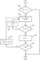
根据本公开的一个方面,公开了一种用于调试使粒料和/或木屑形式的燃料燃烧的生物质加热系统的方法;该生物质加热系统包括具有燃烧腔室的锅炉、送风机和具有存储器和显示器的控制装置,其中该方法包括下述步骤:According to one aspect of the present disclosure, there is disclosed a method for commissioning a biomass heating system that burns fuel in the form of pellets and/or wood chips; the biomass heating system comprising a boiler having a combustion chamber, a blower and having a storage and a control device for a display, wherein the method comprises the steps of:
查询生物质加热系统是否第一次初始化,其中如果生物质加热系统未第一次初始化,那么该方法终止,并且如果生物质加热系统第一次初始化,那么该方法继续下述步骤:Query whether the biomass heating system is initialized for the first time, wherein if the biomass heating system is not initialized for the first time, the method terminates, and if the biomass heating system is initialized for the first time, the method continues with the following steps:
设定多个热产生参数,该多个热产生参数至少包括下述参数:A plurality of heat generation parameters are set, and the plurality of heat generation parameters include at least the following parameters:
-锅炉类型参数,送风机的工作范围以该锅炉类型参数来限定;-Boiler type parameters, the working range of the blower is limited by the boiler type parameters;
-材料参数,该材料参数限定了待燃烧的一种或多种燃料的性质。- Material parameters defining the properties of the fuel or fuels to be combusted.
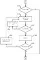
根据进一步发展,提供了一种用于调试使粒料和/或木屑形式的燃料燃烧的生物质加热系统的方法,该方法包括在设定热产生参数的步骤之后的下述步骤:According to a further development, there is provided a method for commissioning a biomass heating system for burning fuel in the form of pellets and/or wood chips, the method comprising the following steps after the step of setting heat generation parameters:
检查该设定的热产生参数的合理性,并且若该合理性检查为否定,则:Check the plausibility of the set heat generation parameters, and if the plausibility check is negative, then:
再次执行设定热产生参数的步骤;在设定参数的合理性检查为肯定的情况下,将设定参数存储于控制装置的存储器中。The step of setting heat generation parameters is performed again; if the plausibility check of the set parameters is positive, the set parameters are stored in the memory of the control device.
根据进一步发展,提供了一种用于调试使粒料和/或木屑形式的燃料燃烧的生物质加热系统的方法,该方法包括在执行合理性检查的步骤之后的下述步骤:According to a further development, there is provided a method for commissioning a biomass heating system for burning fuel in the form of pellets and/or wood chips, the method comprising the following steps after the step of performing a plausibility check:
将关于至少一个缓冲器是否存在的询问显示于显示器上;检测对于关于至少一个缓冲器是否存在的询问的用户响应;在至少一个缓冲器存在的情况下,执行下述步骤:displaying on the display an inquiry about the existence of the at least one buffer; detecting a user response to the inquiry about the existence of the at least one buffer; performing the following steps in the presence of the at least one buffer:
设定至少一个缓冲器参数;并且检查该设定的缓冲器参数的合理性,并若该合理性检查为否定,则:Set at least one buffer parameter; and check the set buffer parameter for plausibility, and if the plausibility check is negative, then:
重复设定该缓冲器参数的步骤。Repeat the steps for setting the buffer parameters.
根据进一步发展,提供了一种用于调试使粒料和/或木屑形式的燃料燃烧的生物质加热系统的方法,该方法包括在执行合理性检查的步骤之后的下述步骤:According to a further development, there is provided a method for commissioning a biomass heating system for burning fuel in the form of pellets and/or wood chips, the method comprising the following steps after the step of performing a plausibility check:
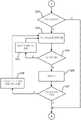
将关于至少一个热水罐是否存在的询问显示于显示器上;检测对于关于至少一个热水罐是否存在的询问的用户响应;在至少一个热水罐存在的情况下,执行下述步骤:Displaying an inquiry about the presence of at least one hot water tank on a display; detecting a user response to the inquiry about the presence of at least one hot water tank; in the presence of at least one hot water tank, performing the following steps:
设定至少一个热水罐参数;并且检查该设定的热水储罐参数的合理性,并若该合理性检查为否定,则:Set at least one hot water tank parameter; and check the rationality of the set hot water storage tank parameter, and if the rationality check is negative, then:
重复设定该热水罐参数的步骤。Repeat the steps for setting the parameters of the hot water tank.
根据进一步发展,提供了一种用于调试使粒料和/或木屑形式的燃料燃烧的生物质加热系统的方法,该方法包括在执行合理性检查的步骤之后的下述步骤:According to a further development, there is provided a method for commissioning a biomass heating system for burning fuel in the form of pellets and/or wood chips, the method comprising the following steps after the step of performing a plausibility check:
将关于至少一个加热回路是否存在的询问显示于显示器上;采集对于关于至少一个加热回路是否存在的询问的用户响应;在至少一个加热回路存在的情况下,执行下述步骤:Displaying an inquiry about the existence of at least one heating circuit on a display; collecting a user response to the inquiry about the existence of at least one heating circuit; performing the following steps in the presence of at least one heating circuit:
设定至少一个加热回路参数;并且检查该设定加热电路参数的合理性,并若该合理性检查为否定,则:Set at least one heating circuit parameter; and check the rationality of the set heating circuit parameter, and if the rationality check is negative, then:
重复设定该加热回路参数的步骤。Repeat the steps for setting the parameters of the heating loop.
根据进一步发展,提供了一种用于调试使粒料和/或木屑形式的燃料燃烧的生物质加热系统的方法,该方法包括在执行合理性检查的步骤之后的下述步骤:According to a further development, there is provided a method for commissioning a biomass heating system for burning fuel in the form of pellets and/or wood chips, the method comprising the following steps after the step of performing a plausibility check:
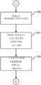
将关于至少一个太阳能模块是否存在的询问显示于显示器上;采集对于关于至少一个太阳能模块是否存在的询问的用户响应;displaying a query regarding the presence of the at least one solar module on a display; collecting a user response to the query regarding the presence of the at least one solar module;
在至少一个太阳能模块存在的情况下,执行下述步骤:In the presence of at least one solar module, the following steps are performed:
设定至少一个太阳能模块参数;并且检查该设定太阳能模块参数的合理性,并若该合理性检查为否定,则:Set at least one solar module parameter; and check the rationality of the set solar module parameter, and if the rationality check is negative, then:
再次执行设定该太阳能模块参数的步骤。Perform the steps of setting the parameters of the solar module again.
根据进一步发展,提供了一种用于调试使粒料和/或木屑形式的燃料燃烧的生物质加热系统的方法,该方法包括下述步骤:According to a further development, there is provided a method for commissioning a biomass heating system for burning fuel in the form of pellets and/or wood chips, the method comprising the steps of:
在显示器上的询问的相应检测已肯定地表示缓冲器和/或热水储罐和/或加热回路和/或太阳能模块存在的情况下,在显示器上创建对应图标以用于显示;将该图标存储于控制装置中。In the event that the corresponding detection of the query on the display has positively indicated the presence of the buffer and/or the hot water storage tank and/or the heating circuit and/or the solar module, a corresponding icon is created on the display for display; the icon stored in the control unit.
根据进一步发展,提供了一种用于调试使粒料和/或木屑形式的燃料燃烧的生物质加热系统的方法,该方法包括下述步骤:According to a further development, there is provided a method for commissioning a biomass heating system for burning fuel in the form of pellets and/or wood chips, the method comprising the steps of:
创建对应图标,以使得对应于图标的传感器参数(其由控制装置来检测)表示于图标中。The corresponding icons are created such that the sensor parameters corresponding to the icons (which are detected by the control device) are represented in the icons.
根据另一实施例,提供了一种布置成执行前述方法的计算机程序。According to another embodiment, there is provided a computer program arranged to perform the aforementioned method.
根据另一实施例,提供了一种包括上述计算机程序的计算机可读存储介质。According to another embodiment, there is provided a computer-readable storage medium including the above-described computer program.
虽然本发明的一个方面和该方面的实施例的所有前述独立特征和细节结合生物质加热系统来描述,但是这些独立特征和细节也参考独立于生物质加热系统的系统控制装置来公开。While all of the foregoing independent features and details of an aspect of the invention and embodiments of this aspect are described in conjunction with a biomass heating system, these independent features and details are also disclosed with reference to a system control device independent of the biomass heating system.
此外,烟道气体再循环装置、过渡螺杆、初级混合单元、次级混合单元和烟道气体冷凝器独立于生物质加热系统和安装方法进行描述,并且可因此独立地要求保护。Furthermore, the flue gas recirculation device, transition screw, primary mixing unit, secondary mixing unit and flue gas condenser are described independently of the biomass heating system and installation method, and may therefore be independently claimed.
根据本公开的互补方面,相应地提供了一种用于使粒料和/或木屑形式的燃烧的生物质加热系统,该设施包括:锅炉,该锅炉具有燃烧器;换热器,该换热器具有入口和出口;燃烧装置包括具有初级燃烧区域和设置于其下游的次级燃烧区域的燃烧腔室;燃烧腔室的次级燃烧区域流体地连接至换热器的入口;初级燃烧区域由多个燃烧腔室砖侧向地围封。According to complementary aspects of the present disclosure, there is accordingly provided a biomass heating system for the combustion of pellets and/or wood chips, the installation comprising: a boiler having a burner; a heat exchanger, the heat exchange The burner has an inlet and an outlet; the combustion device includes a combustion chamber having a primary combustion zone and a secondary combustion zone disposed downstream thereof; the secondary combustion zone of the combustion chamber is fluidly connected to the inlet of the heat exchanger; the primary combustion zone is composed of A plurality of combustion chamber tiles are enclosed laterally.
这种配置以及下述方面的优点根据相关实施例的下述描述将为显而易见的。The advantages of this configuration, as well as the aspects described below, will be apparent from the following description of related embodiments.
根据先前方面的进一步发展,提供了一种生物质加热系统,该生物质加热系统还包括:再循环器具,该再循环器具用于使在燃料的燃烧时所产生的烟道气体在燃烧设备中再循环;其中再循环器具包括:再循环入口,该再循环入口设置于换热器的出口的下游并且流体地连接至该出口;和初级空气通路,该初级空气通路用于供应初级空气;初级混合单元,该初级混合单元具有初级混合腔室和初级混合通路,该初级混合腔室设置于再循环入口和初级空气通路的下游并且流体地连接至再循环入口和初级空气通路;和至少两个空气阀,该至少两个空气阀设置于初级混合腔室的入口侧上;和至初级燃烧区域中的初级通路,该初级通路设置于并且流体地连接初级混合管道的下游;其中初级混合单元适于通过初级混合腔室的至少两个空气阀使来自再循环入口的烟道气体与初级空气管道的初级空气混合。According to a further development of the previous aspect, a biomass heating system is provided, the biomass heating system further comprising: recirculation means for causing flue gas generated during the combustion of the fuel in the combustion device recirculation; wherein the recirculation means comprises: a recirculation inlet disposed downstream of and fluidly connected to an outlet of the heat exchanger; and a primary air passage for supplying primary air; primary a mixing unit having a primary mixing chamber and a primary mixing passage, the primary mixing chamber being disposed downstream of the recirculation inlet and the primary air passage and fluidly connected to the recirculation inlet and the primary air passage; and at least two an air valve, the at least two air valves provided on the inlet side of the primary mixing chamber; and a primary passage to the primary combustion zone, the primary passage being provided and fluidly connected downstream of the primary mixing duct; wherein the primary mixing unit is adapted The flue gas from the recirculation inlet is mixed with the primary air of the primary air duct through at least two air valves of the primary mixing chamber.
根据先前方面的另一方面,提供了一种生物质加热系统,该生物质加热系统还包括以下项:初级混合管道直接地连接至初级混合腔室的初级混合腔室出口,并且初级混合管道设置于初级混合腔室的下游。According to another aspect of the previous aspect, there is provided a biomass heating system, the biomass heating system further comprising: the primary mixing conduit is directly connected to the primary mixing chamber outlet of the primary mixing chamber, and the primary mixing conduit is provided downstream of the primary mixing chamber.
根据先前方面的另一实施例,提供了一种生物质加热系统,该生物质加热系统还包括以下项:初级混合管道以直线方式延伸并且具有从开端至终端的700mm的最小长度。According to another embodiment of the previous aspect, there is provided a biomass heating system further comprising the following: the primary mixing duct extends in a straight line and has a minimum length of 700mm from start to end.
根据先前方面的另一实施例,提供了一种生物质加热系统,该生物质加热系统还包括以下项:初级混合腔室的空气阀为旋转滑阀,其各自包括阀本体,该阀本体具有至少一个新月形阀叶并且具有通向初级混合腔室中的至少一个对应新月形阀通路。根据先前方面的另一方面,提供了一种生物质加热系统,该生物质加热系统还包括以下项:初级混合腔室在出口侧上具有初级混合腔室出口;初级混合腔室在入口侧上具有至少两个阀通路开口;并且初级混合腔室布置成使得至少两个阀通路开口和初级混合腔室出口不通过初级混合腔室面向彼此,使得通过至少两个阀通路开口进入初级混合腔室的流在初级混合腔室中进行偏转或重新导向。According to another embodiment of the previous aspect, there is provided a biomass heating system, the biomass heating system further comprising the following: the air valves of the primary mixing chamber are rotary spool valves each including a valve body having a At least one crescent valve leaf and has at least one corresponding crescent valve passageway into the primary mixing chamber. According to another aspect of the previous aspect, there is provided a biomass heating system further comprising: the primary mixing chamber has a primary mixing chamber outlet on the outlet side; the primary mixing chamber is on the inlet side having at least two valve passage openings; and the primary mixing chamber is arranged such that the at least two valve passage openings and the primary mixing chamber outlet do not face each other through the primary mixing chamber such that entry into the primary mixing chamber passes through the at least two valve passage openings The flow is deflected or redirected in the primary mixing chamber.
根据先前方面的进一步发展,提供了一种生物质加热系统该生物质加热系统还包括以下项:再循环单元,该再循环单元还包括以下项:次级空气管道,该次级空气管道用于供应次级空气;次级混合单元,该次级混合单元具有次级混合腔室和次级混合管道,该次级混合腔室设置于并且流体地连接至再循环入口和次级空气管道的下游;和至少两个空气阀,该至少两个空气阀设置于次级混合腔室的上游;和次级空气喷嘴,这些次级空气喷嘴设置于燃烧腔室砖中并侧向地导向至初级燃烧区域中,并且设置于次级混合管道的下游并流体地连接至次级混合管道;次级混合单元布置成通过次级混合腔室的至少两个空气阀将再循环入口的烟道气体与次级空气管道的次级空气混合。According to a further development of the previous aspect, a biomass heating system is provided, the biomass heating system further comprising: a recirculation unit, the recirculation unit further comprising: a secondary air duct for supplying secondary air; a secondary mixing unit having a secondary mixing chamber and a secondary mixing duct disposed and fluidly connected downstream of the recirculation inlet and the secondary air duct ; and at least two air valves disposed upstream of the secondary mixing chamber; and secondary air nozzles disposed in the combustion chamber tiles and directed laterally to the primary combustion The secondary mixing unit is arranged to recirculate inlet flue gas to the secondary mixing duct through at least two air valves of the secondary mixing chamber. Secondary air mixing in the primary air duct.
根据前述方面的另一方面,提供了一种生物质加热系统,该生物质加热系统还包括:烟道气体冷凝器,该烟道气体冷凝器设置于并且流体地连接至换热器的下游;其中:所述烟道气体冷凝器具有第一流体端口和第二流体端口以用于使热交换介质流动至所述烟道气体冷凝器;并且所述烟道气体冷凝器具有多个U形热交换管,所述多个U形热交换管以多组布置成在第一方向上彼此平行;其中所述多组的所述换热器管在第二方向上布置成彼此平行;其中所述多组的所述换热器管在所述流体端口和所述第二流体端口之间彼此流体地串联连接;所述多个所述U形换热器管布置成相对于所述烟道气体穿过所述多个换热器管的流而形成交叉逆流配置。According to another aspect of the preceding aspect, there is provided a biomass heating system further comprising: a flue gas condenser disposed and fluidly connected downstream of the heat exchanger; wherein: the flue gas condenser has a first fluid port and a second fluid port for flowing a heat exchange medium to the flue gas condenser; and the flue gas condenser has a plurality of U-shaped heat exchangers exchange tubes, the plurality of U-shaped heat exchange tubes are arranged in groups to be parallel to each other in a first direction; wherein the heat exchanger tubes of the plurality of groups are arranged to be parallel to each other in a second direction; wherein the sets of said heat exchanger tubes are fluidly connected in series with each other between said fluid port and said second fluid port; said plurality of said U-shaped heat exchanger tubes are arranged relative to said flue gas The flow through the plurality of heat exchanger tubes forms a cross-countercurrent configuration.
根据先前方面的进一步发展,提供了一种生物质加热系统,该生物质加热系统还包括以下项:多个U形换热器管布置成使得它们在第二方向上形成流体连续通道以用于烟道气体流动穿过,其中该通道具有6.0mm+-0.5mm的(水平)最小宽度SP2。According to a further development of the previous aspect, there is provided a biomass heating system further comprising: a plurality of U-shaped heat exchanger tubes arranged such that they form a fluid continuous channel in a second direction for The flue gas flows through, wherein the channel has a (horizontal) minimum width SP2 of 6.0mm+-0.5mm.
根据先前方面的另一实施例,提供了一种生物质加热系统,该生物质加热系统还包括以下项:所有U形换热器管的端部布置成容纳于板形管片材构件中;并且7个至12个,优选地8个至10个数量的换热器管493各自作为组布置于第一方向上;8组至14组,优选地10组至12组数量的换热器管493布置于第二方向上。According to another embodiment of the previous aspect, there is provided a biomass heating system, the biomass heating system further comprising: the ends of all U-shaped heat exchanger tubes are arranged to be accommodated in plate tube sheet members; And 7 to 12, preferably 8 to 10 number of
根据先前方面的进一步发展,提供了一种生物质加热系统,该生物质加热系统还包括以下项:U形换热器管具有421mm+-50mm的最大长度;和/或由材料1.4462制成(如本申请的提交日期所定义)。According to a further development of the previous aspect, there is provided a biomass heating system, the biomass heating system further comprising the following: the U-shaped heat exchanger tubes have a maximum length of 421mm+-50mm; and/or are made of material 1.4462 (eg as defined by the filing date of this application).
根据先前方面的进一步发展,提供了一种生物质加热系统,该生物质加热系统还包括:排灰螺杆,该排灰螺杆用于将燃烧残留物输送离开锅炉;其中排灰螺杆包括过渡螺杆,该过渡螺杆可旋转地容纳于过渡螺杆外壳中并且具有逆向旋转。According to a further development of the previous aspect, a biomass heating system is provided, the biomass heating system further comprising: an ash discharge screw for conveying combustion residues away from the boiler; wherein the ash discharge screw comprises a transition screw, The transition screw is rotatably received in the transition screw housing and has counter-rotation.
根据先前方面的另一实施例,提供了一种生物质加热系统,该生物质加热系统还包括以下项:过渡螺杆外壳中的燃烧残留物在排灰螺杆的旋转时进行压实,使得燃烧腔室和换热器的出口之间的燃烧残留物至少大体上相对于烟道气体进行分离或气体紧密地密封。According to another embodiment of the previous aspect, a biomass heating system is provided, the biomass heating system further comprising the following: combustion residues in the transition screw housing are compacted upon rotation of the ash discharge screw such that the combustion chamber is The combustion residues between the chamber and the outlet of the heat exchanger are at least substantially separated or gas-tightly sealed with respect to the flue gas.
根据先前方面的另一实施例,提供了一种生物质加热系统,该生物质加热系统还包括以下项:过渡螺杆外壳包括向上开放开口,该向上开放开口通过料斗构件来包围,并且过渡螺杆的逆向旋转布置成使得燃烧残留物在排灰螺杆的旋转时从开口向上排出。According to another embodiment of the previous aspect, there is provided a biomass heating system, the biomass heating system further comprising the following: the transition screw housing includes an upwardly open opening surrounded by a hopper member, and the transition screw The counter-rotation is arranged so that the combustion residues are discharged upwards from the opening upon rotation of the ash discharge screw.
根据先前方面的另一实施例,提供了一种生物质加热系统,该生物质加热系统还包括以下项:排灰螺杆在过渡螺杆的一侧上具有相比于在过渡螺杆的另一侧上的较大直径。According to another embodiment of the previous aspect, there is provided a biomass heating system, the biomass heating system further comprising the following: the ash discharge screw has on one side of the transition screw compared to on the other side of the transition screw the larger diameter.
在该语境中,“水平”可指代轴向或横截面的平坦取向,假设锅炉也水平地安装,由此地面可为例如基准。替代地,如本文所用,“水平”可意指“平行于”锅炉的基部平面,如通常所定义。还替代地,特别在不存在基准平面的情况下,“水平”可理解为意指仅“平行于”炉排的燃烧平面。In this context, "horizontal" may refer to an axial or cross-sectional flat orientation, assuming that the boiler is also installed horizontally, whereby the ground may eg be a datum. Alternatively, as used herein, "horizontal" may mean "parallel to" the base plane of the boiler, as generally defined. Also alternatively, "horizontal" may be understood to mean only "parallel" to the combustion plane of the grate, especially in the absence of a reference plane.
虽然本发明的一个方面和该方面的实施例的所有前述独立特征和细节结合生物质加热系统和再循环装置来描述,但是这些独立特征和细节也独立于生物质加热系统来公开。Although all of the foregoing independent features and details of an aspect of the invention and embodiments of this aspect are described in conjunction with the biomass heating system and the recirculation device, these independent features and details are also disclosed independently of the biomass heating system.
特别地,烟道气体再循环装置、过渡螺杆、初级混合单元、次级混合单元和烟道气体冷凝器独立于生物质加热系统进行描述,并且可因此独立地要求保护。In particular, the flue gas recirculation device, transition screw, primary mixing unit, secondary mixing unit and flue gas condenser are described independently of the biomass heating system and can therefore be claimed independently.
就此而言,额外地公开了一种再循环装置,该再循环装置用于使在燃料的燃烧时所产生的烟道气体在燃烧装置中再循环,该再循环装置包括以下项:再循环入口,该再循环入口适于设置于换热器的出口的下游并且流体地连接至该出口;和初级空气通路,该初级空气通路用于供应初级空气;初级混合单元,该初级混合单元具有初级混合腔室和初级混合通路,该初级混合腔室设置于再循环入口和初级空气通路的下游并且流体地连接至再循环入口和初级空气通路;和至少两个空气阀,该至少两个空气阀设置于初级混合腔室的入口侧处;和至初级燃烧区域中的初级通路,该初级通路设置于并且流体地连接至初级混合管道的下游;其中初级混合单元适于通过初级混合腔室的至少两个空气阀使再循环入口的烟道气体与初级空气管道的初级空气混合。In this regard, a recirculation device is additionally disclosed for recirculating the flue gas produced during the combustion of the fuel in the combustion device, the recirculation device comprising the following: a recirculation inlet , the recirculation inlet is adapted to be disposed downstream of and fluidly connected to the outlet of the heat exchanger; and a primary air passage for supplying primary air; a primary mixing unit having a primary mixing unit a chamber and a primary mixing passage disposed downstream of the recirculation inlet and the primary air passage and fluidly connected to the recirculation inlet and the primary air passage; and at least two air valves disposed at the inlet side of the primary mixing chamber; and a primary passage into the primary combustion region, the primary passage being arranged and fluidly connected downstream of the primary mixing duct; wherein the primary mixing unit is adapted to pass through at least two of the primary mixing chambers; An air valve mixes the flue gas at the recirculation inlet with the primary air in the primary air duct.
这种再循环装置可与本文所公开的其它方面和独立特征相组合,如技术人员在技术上视为可行的。Such a recirculation device may be combined with other aspects and individual features disclosed herein, as deemed technically feasible by the skilled person.
还公开了一种烟道气体冷凝器,该烟道气体冷凝器可连接至锅炉的废气出口;其中:所述烟道气体冷凝器具有第一流体端口/第一流体连接部和第二流体端口/第二流体连接部以用于使热交换介质流动至所述烟道气体冷凝器;并且所述烟道气体冷凝器具有多个U形热交换管,所述多个U形热交换管以多组布置成在第一方向上彼此平行;其中所述多组的所述换热器管在第二方向上布置成彼此平行;其中所述多组的所述换热器管在所述流体端口和所述第二流体端口之间彼此流体地串联连接;所述多个所述U形换热器管布置成相对于所述烟道气体穿过所述多个换热器管的流而形成交叉逆流配置。Also disclosed is a flue gas condenser connectable to an exhaust gas outlet of a boiler; wherein: the flue gas condenser has a first fluid port/first fluid connection and a second fluid port / a second fluid connection for flowing a heat exchange medium to the flue gas condenser; and the flue gas condenser has a plurality of U-shaped heat exchange tubes with a plurality of sets are arranged parallel to each other in a first direction; wherein the heat exchanger tubes of the plurality of sets are arranged parallel to each other in a second direction; wherein the heat exchanger tubes of the plurality of sets are arranged parallel to each other in the fluid the ports and the second fluid port are fluidly connected in series with each other; the plurality of the U-shaped heat exchanger tubes are arranged in a manner that is in a relative manner to the flow of the flue gas through the plurality of heat exchanger tubes A cross-countercurrent configuration is formed.
这种烟道气体冷凝器可与其它方面和独立特征相组合,如技术人员在技术上视为可行的。Such a flue gas condenser can be combined with other aspects and independent features, as the skilled person considers technically feasible.
还公开了一种排灰螺杆,该排灰螺杆用于将燃烧残留物从生物质加热系统的锅炉输送出来;所述排灰螺杆包括过渡螺杆,该过渡螺杆可旋转地容纳于过渡螺杆外壳中并且具有逆向旋转。Also disclosed is an ash discharge screw for conveying combustion residues from a boiler of a biomass heating system; the ash discharge screw includes a transition screw that is rotatably accommodated in a transition screw casing and has reverse rotation.
这种排灰螺杆可与其它方面和独立特征相组合,如技术人员在技术上视为可行的。Such an ash discharge screw can be combined with other aspects and independent features, as the skilled person considers technically feasible.
附图说明Description of drawings
基于附图中的图而在下文在实施例实例和独立方面更详细地解释根据本发明的生物质加热系统:The biomass heating system according to the present invention is explained in more detail below in terms of embodiment examples and independent aspects on the basis of the figures in the accompanying drawings:
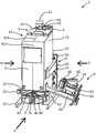
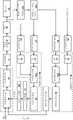
图1示出了根据本发明的一个实施例的生物质加热系统的三维概况视图;Figure 1 shows a three-dimensional overview view of a biomass heating system according to one embodiment of the present invention;
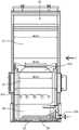
图2示出了横穿图1的生物质加热系统的剖视图,该剖视图沿着剖面线SL1来制成并且如从侧视图S所观察来示出;FIG. 2 shows a cross-sectional view across the biomass heating system of FIG. 1 , taken along section line SL1 and as viewed from side view S;
图3也示出了横穿图1的生物质加热系统的剖视图,表示有流动路线,该剖视图已沿着剖面线SL1来制成并且如从侧视图S所观察来示出;FIG. 3 also shows a cross-sectional view across the biomass heating system of FIG. 1, showing the flow path, which has been made along section line SL1 and shown as viewed from side view S;
图4示出了图2的局部视图,从而示出图2和图3的锅炉的燃烧腔室几何图形;Fig. 4 shows a partial view of Fig. 2 to illustrate the combustion chamber geometry of the boiler of Figs. 2 and 3;
图5示出了沿着图4的竖直剖面线A2截穿锅炉或锅炉的燃烧腔室的剖视图;Fig. 5 shows a cross-sectional view through the boiler or the combustion chamber of the boiler along the vertical section line A2 of Fig. 4;
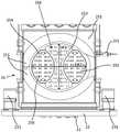
图6示出了图4的旋转炉排的燃烧腔室的初级燃烧区域的三维剖视图;FIG. 6 shows a three-dimensional cross-sectional view of the primary combustion region of the combustion chamber of the rotary grate of FIG. 4;
图7示出了图6的燃烧腔室砖的分解图;Figure 7 shows an exploded view of the combustion chamber tile of Figure 6;
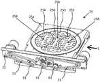
图8示出了如从图2的剖面线A1所见的具有旋转炉排元件的旋转炉排的顶视图;Figure 8 shows a top view of a rotary grate with rotary grate elements as seen from section line A1 of Figure 2;
图9示出了处于闭合位置的图2的旋转炉排,其中所有旋转炉排元件水平地对准或闭合;Figure 9 shows the rotary grate of Figure 2 in a closed position with all rotary grate elements aligned or closed horizontally;
图10示出了以辉光维护模式处于旋转炉排的局部清洁状态的图9的旋转炉排;Figure 10 shows the rotary grate of Figure 9 in a partially cleaned state of the rotary grate in glow maintenance mode;
图11示出了处于全体清洁状态的图9的旋转炉排,该全体清洁优选地在系统停机期间执行;Figure 11 shows the rotary grate of Figure 9 in a general cleaning state, preferably performed during system shutdown;
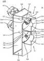
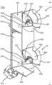
图12示出了示例性再循环装置的突出显示斜视图,该图示出有围绕初级燃烧区域的燃烧腔室砖;FIG. 12 shows a highlighted oblique view of an exemplary recirculation apparatus showing combustion chamber tiles surrounding a primary combustion zone;
图13示出了图12的再循环装置的突出显示半透明斜视图;Figure 13 shows a highlighted translucent oblique view of the recirculation device of Figure 12;
图14示出了图12和图13的再循环装置5的侧视图;Figure 14 shows a side view of the
图15示出了示意性框图,从而示出图12至图14的生物质加热系统和再循环装置的相应独立部件中的流动模式;Figure 15 shows a schematic block diagram illustrating flow patterns in respective separate components of the biomass heating system and recirculation device of Figures 12-14;
图16示出了示例性初级混合腔室以及两个入口侧(初级)空气阀52的剖视图,对应于图12和图13的外部视图,两个入口侧(初级)空气阀52从斜视角度具有其(初级)阀前/预腔室525;Figure 16 shows a cross-sectional view of an exemplary primary mixing chamber and two inlet side (primary)
图17示出了关于可选次级再循环的示例性次级混合腔室以及两个入口侧(次级)空气阀的剖视图,对应于图12和图13的外部视图,该两个入口侧(次级)空气阀从另一斜视角度具有其(次级)阀预腔室;17 shows a cross-sectional view of an exemplary secondary mixing chamber with optional secondary recirculation and two inlet side (secondary) air valves, corresponding to the external views of FIGS. 12 and 13 , the two inlet side The (secondary) air valve has its (secondary) valve pre-chamber from another oblique angle;
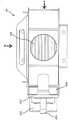
图18示出了图1的生物质加热系统的三维概况视图,该生物质加热系统具有额外的外壳体/外部包层和额外烟道气体冷凝器;Figure 18 shows a three-dimensional overview view of the biomass heating system of Figure 1 with an additional outer casing/outer cladding and additional flue gas condenser;
图19a以从图18的箭头H的方向的侧视图示出了图18的烟道气体冷凝器49;Figure 19a shows the
图19b以从图18的箭头V的方向的侧视图示出了图18的烟道气体冷凝器49;Figure 19b shows the
图20示出了图19a和图18的烟道气体冷凝器的内部视图;Figure 20 shows an interior view of the flue gas condenser of Figures 19a and 18;
图21从观察烟道气体冷凝器的烟道气体供应管道的开口中的顶视图示出了烟道气体冷凝器;Figure 21 shows the flue gas condenser from a top view looking into the opening of the flue gas supply conduit of the flue gas condenser;
图22示出了图18的烟道气体冷凝器的顶视水平剖视图;Figure 22 shows a top horizontal cross-sectional view of the flue gas condenser of Figure 18;
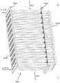
图23示出了多个换热器管的三维视图,该换热器管具有管片材构件和管支撑构件/管状底板元件;Figure 23 shows a three-dimensional view of a plurality of heat exchanger tubes having tube sheet members and tube support members/tubular floor elements;
图24示出了图23的多个换热器管的侧视图;Figure 24 shows a side view of the plurality of heat exchanger tubes of Figure 23;
图25示出了图23的多个换热器管的顶视图;Figure 25 shows a top view of the plurality of heat exchanger tubes of Figure 23;
图26示出了图23的多个换热器管的顶视图;Figure 26 shows a top view of the plurality of heat exchanger tubes of Figure 23;
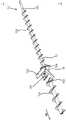
图27a示出了从图2和图3所提取的具有过渡螺杆的排灰螺杆的剖视图;Figure 27a shows a cross-sectional view of the ash discharge screw with transition screw taken from Figures 2 and 3;
图27b示出了图27a的排灰螺杆的三维斜视图;Figure 27b shows a three-dimensional oblique view of the ash discharge screw of Figure 27a;
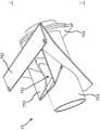
图28示出了过渡螺杆的外壳的三维斜视图;Figure 28 shows a three-dimensional oblique view of the housing of the transition screw;
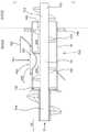
图29示出了图27a的具有过渡螺杆的排灰螺杆的剖视图的详细视图;Figure 29 shows a detailed view of a cross-sectional view of the ash discharge screw with transition screw of Figure 27a;
图30根据图1至图29的实施例的一者示出了用于调试使粒料和/或木屑形式的燃料燃烧的生物质加热系统的方法;30 illustrates a method for commissioning a biomass heating system that combusts fuel in the form of pellets and/or wood chips, according to one of the embodiments of FIGS. 1-29;
图31示出了延续图30的用于调试生物质加热系统的方法的可选方法部分;FIG. 31 shows an optional method portion of the method for commissioning a biomass heating system that continues with FIG. 30;
图32示出了延续图30或图31的用于调试生物质加热系统的方法的可选方法部分;FIG. 32 shows an optional method portion of the method for commissioning a biomass heating system continuing with FIG. 30 or FIG. 31;
图33示出了延续图30、图31或图32的用于调试生物质加热系统的方法的可选方法部分;FIG. 33 shows an optional method portion of the method for commissioning a biomass heating system continuing with FIG. 30 , FIG. 31 or FIG. 32 ;
图34示出了延续图30、图31、图32或图33的用于调试生物质加热系统的方法的可选方法部分;Fig. 34 shows an optional method portion of the method for commissioning a biomass heating system continuing with Fig. 30, Fig. 31, Fig. 32 or Fig. 33;
图35示出了延续图30、图31、图32、图33、图34或图35的用于调试生物质加热系统的方法的可选方法部分;Figure 35 shows an optional method portion of the method for commissioning a biomass heating system in continuation of Figure 30, Figure 31, Figure 32, Figure 33, Figure 34, or Figure 35;
图36示出了图18的生物质加热系统的控制装置的显示器的示例性表示。FIG. 36 shows an exemplary representation of a display of the control device of the biomass heating system of FIG. 18 .
具体实施方式Detailed ways
本公开的各种实施例现参考附图进行公开。然而,其中所用的实施例和术语非旨在将本公开限制于特定实施例,并且应理解为包括根据本公开的实施例的各种修改、等同物和/或替代物。Various embodiments of the present disclosure are now disclosed with reference to the accompanying drawings. However, the embodiments and terminology used therein are not intended to limit the present disclosure to particular embodiments, and are to be understood to include various modifications, equivalents, and/or alternatives to embodiments of the present disclosure.
更通用术语应在描述中用于附图所示的特征或元件;据预期,对于本领域技术人员而言,附图不仅公开了具体特征或元件,而且公开了更通用技术教导。More general terms should be used in the description for the features or elements shown in the drawings; it is expected to those skilled in the art that the drawings disclose not only specific features or elements, but also more general technical teachings.
参考附图的描述,相同附图标号可在每个图中用于指代类似或技术上对应元件。此外,为清晰起见,更多元件或特征可在独立细节或剖视图(而非在概况视图)中以附图标号来示出。可假设,这些元件或特征还可在概况图示中相应地公开,即使它们未在其中明确地列出。In the description with reference to the figures, the same reference numerals may be used in each figure to refer to similar or technically corresponding elements. Furthermore, for clarity, further elements or features may be shown with reference numerals in separate detail or cross-sectional views (rather than in overview views). It is assumed that these elements or features may also be correspondingly disclosed in the overview diagrams even if they are not explicitly listed therein.
应当理解,对应于物体的名词的单数形式可包括该事物的一者或多者,除非有关语境另行明显地指示。It should be understood that the singular form of a noun corresponding to an object may include one or more of that object, unless the relevant context clearly dictates otherwise.
在本公开中,诸如“A或B”、“A或/和B的至少一者”或“A或/和B的一者或多者”的表达可包括所一起列出特征的所有可能组合。本文所用的诸如“第一”、“第二”、“初级”或“次级”的表达可表示不同元件而不考虑其次序和/或意义,和/或未限制对应元件。当描述一个元件(例如,第一元件)“可操作地”或“通信地”联接或连接至另一元件(例如,第二元件)时,该元件可直接地连接至其它元件,或经由另一元件(例如,第三元件)连接至其它元件。In the present disclosure, expressions such as "A or B", "at least one of A or/and B" or "one or more of A or/and B" may include all possible combinations of the features listed together . As used herein, expressions such as "first," "second," "primary," or "secondary" may represent different elements without regard to their order and/or meaning, and/or without limiting corresponding elements. When an element (eg, a first element) is described as being "operably" or "communicatively" coupled or connected to another element (eg, a second element), the element can be directly connected to the other element or via another element An element (eg, a third element) is connected to other elements.
例如,本公开所用的术语“配置成”(或“设置”)可以“适合于”、“适于”、“制成用于”、“能够”或“设计成”来替换,如技术上可能的。另选地,在特定情形下,表达“配置成......的装置”或“设置成”可意指,该装置可结合另一装置或部件进行操作,或可执行对应功能。For example, the term "configured to" (or "arranged to") as used in this disclosure may be replaced by "suitable for," "adapted to," "made to," "capable of," or "designed to," as technically possible of. Alternatively, the expressions "means configured to" or "arranged to" may mean, in a particular context, that the device may operate in conjunction with another device or component, or may perform a corresponding function.
以“mm”给出的所有尺寸规格应理解为规定数值+-1mm的尺寸范围,除非明确地规定另一公差或其它范围。All dimensional specifications given in "mm" should be understood as specifying a dimensional range of the numerical value +-1 mm unless another tolerance or other range is expressly specified.
应指出的是,本发明独立方面(例如,旋转炉排、燃烧腔室或过滤装置)公开为独立于本文的生物质加热系统或与之分离的独立部分或独立装置。因此,对于本领域技术人员明显的是,独立方面或系统部分也公开于本文,即使以隔离方式。在这种情况下,该系统的独立方面或部分特别地公开于由括号所标记的子章节中。据设想,这些独立方面还可单独地要求保护。It should be noted that individual aspects of the invention (eg, rotary grate, combustion chamber, or filtration device) are disclosed as separate parts or separate devices independent of or separate from the biomass heating system herein. Thus, it will be apparent to those skilled in the art that independent aspects or parts of the system are also disclosed herein, even in isolation. In this case, independent aspects or parts of the system are specifically disclosed in subsections marked by parentheses. It is envisaged that these independent aspects may also be claimed separately.
另外,为清晰起见,并非所有特征和元件在附图中独立地标出,特别是在它们重复的话。相反,元件和特征各自通过示例的方式来标出。类似或等同元件然后也如此理解。In addition, in the interest of clarity, not all features and elements are individually identified in the drawings, especially where they are repeated. Rather, elements and features have each been identified by way of example. Similar or equivalent elements are then also to be understood as such.
(生物质加热系统)(biomass heating system)
图1示出了根据本发明的一个实施例的生物质加热系统1的三维概况视图。Figure 1 shows a three-dimensional overview view of a
在图中,箭头V表示系统1的前视图,并且箭头S表示系统1在图中的侧视图。In the figures, the arrow V represents the front view of the
生物质加热系统1具有锅炉11,锅炉11支撑于锅炉基部12上。锅炉11具有锅炉外壳13,锅炉外壳13例如由片材钢制成。The
在锅炉11的前部分中,存在燃烧装置2(未示出),燃烧装置2可经由具有闸板21的第一维护开口来到达。旋转炉排25(未示出)的旋转机构安装件/托架22支撑旋转机构23,旋转机构23可用于将驱动力传递至旋转炉排25的轴承轴。In the front part of the
在锅炉11的中心部分中,存在换热器3(未示出),换热器3可从上方经由具有闸板31的第二维护开口来到达。In the central part of the
锅炉11的后部为具有电极44(未示出)的可选过滤装置4(未示出);电极44由绝缘电极支撑件/保持器43悬挂,并通过电极供应线42来通电。生物质加热系统1的废气经由废气出口41来排出,废气出口41(流体地)布置于过滤装置4的下游。风扇可设置于此处。At the rear of the
再循环装置5设置于锅炉11的下游以使烟道气体或废气的一部分再循环通过再循环管道54和55以及空气阀52以用于在燃烧过程中重新使用。该再循环装置5将在下文参考图12至图17详细地解释。A
另外,生物质加热系统1具有燃料供应部6,燃料通过燃料供应部6以受控方式从旋转炉排25上的侧部输送至燃烧装置2的初级燃烧区域26中。燃料供应部6具有带有燃料供应开口/端口65的旋转阀61,旋转阀61具有带有控制电子器件的驱动电机66。由驱动电机66所驱动的轴62驱动平移机构63,平移机构63可驱动燃料进给螺杆67(未示出),使得燃料在燃料进给管道64中进给至燃料装置2。In addition, the
排灰装置7设置于生物质加热系统1的下部部分,排灰装置7在排灰管道中具有排灰螺杆71以及过渡螺杆73,排灰螺杆71通过电机72来操作。The
图2现示出了穿过图1的生物质加热系统1的剖视图,该剖视图已沿着剖面线SL1制成并且如从侧视图S所观察来示出。在示出与图2相同的横截面的对应图3中,为清晰起见,示意性地示出了烟道气体的流和流体连接部。参考图3,应当指出的是,相比于图2,独立区域示为暗色。这仅出于图3的清晰性和流动箭头S5,S6和S7的可视性。FIG. 2 now shows a sectional view through the
从左至右,图2示出了锅炉11的燃烧装置2、换热器3和(可选的)过滤装置4。锅炉11支撑于锅炉基部/足部12上,并且具有多壁锅炉外壳13,水或其它流体热交换介质可在多壁锅炉外壳13中循环。具有泵、阀、管材、管等的水循环装置14设置用于供应和排出热交换介质。From left to right, FIG. 2 shows the
燃烧装置2具有燃烧腔室24,燃料的燃烧过程在燃烧腔室24的核心处进行。燃烧腔室24具有多件式旋转炉排25(下文更详细地解释),燃料床28搁置于多件式旋转炉排25上。多件式旋转炉排25可通过多个轴承轴81进行旋转地安装。The
还参考图2,燃烧腔室24的初级燃烧区域26由(多个)燃烧腔室砖29来围封,由此燃烧腔室砖29限定了初级燃烧区域26的几何图形。(例如)沿着水平剖面线A1的初级燃烧区域26的横截面为大体卵形的(例如,380mm+-60mm×320mm+-60mm;应当指出的是,一些上述尺寸组合还可得到圆形横截面)。对应图3的箭头S1示意性地示出了初级燃烧区域26中的初级流,该初级流也(未更详细地示出)具有漩涡以改善烟道气体的混合。燃烧腔室砖29形成初级燃烧区域26的内衬层,存储热量,并且直接地暴露于火焰。因此,燃烧腔室砖29还保护燃烧腔室24的其它材料(诸如铸铁)免于在燃烧腔室24中的直接火焰暴露。燃烧腔室砖29优选地适于炉排25的形状。燃烧腔室砖29还包括次级空气或再循环喷嘴291,次级空气或再循环喷嘴291使烟道气体再循环至初级燃烧区域26中以用于燃烧过程的重新参与。就此而言,次级空气喷嘴或再循环喷嘴291未取向朝向初级燃烧区域26的中心,而是偏心地取向以引起初级燃烧区域26中的流的漩涡(即,涡旋流)。燃烧腔室砖29将在下文更详细地讨论。绝缘物311设置于锅炉管入口处。初级燃烧区域26(和喷嘴)的卵形横截面形状有利地促进涡旋流的形成。Referring also to FIG. 2 , the
次级燃烧区域27邻接燃烧腔室26的初级燃烧区域26,并且限定了燃烧腔室26的辐射部分。在辐射部段/对流部分,在燃烧期间所产生的烟道气体主要通过热辐射而放出其热能量,特别地放出至热交换介质,该热能量位于热交换介质38的两个左腔室中。对应烟道气体流在图3中通过箭头S2和S3来指示。第一维护开口21以绝缘材料(例如VermiculiteTM)进行绝缘。该次级燃烧区域27布置成确保烟道气体的烧尽。次级燃烧区域27的具体几何设计将在下文更详细地讨论。
在次级燃烧区域27之后,烟道气体就通过入口33流动至换热器3中,换热器3具有设置成彼此平行的一束锅炉管32。烟道气体现在锅炉管32中向下流动,如通过图3的箭头S4所指示。该部分的流还可称为对流部分,因为烟道气体的散热经由强制对流基本上发生于锅炉管壁处。由于在锅炉11的热交换介质(例如,水)中所引起的温度梯度,水的自然对流得以建立,这有利于锅炉水的混合。After the
弹簧湍流器36和螺旋或带状湍流器37布置于锅炉管32中,以改善热交换装置4的效率。
锅炉管32的出口经由逆转/转动腔室入口34而打开,腔室入口34对应于转动腔室35的入口。在这种情况下,转动腔室35与燃烧腔室24密封,以使得烟道气体不可从转动腔室35直接地返回流动至燃烧腔室24中。然而,共同(排出)运输路径仍设置用于燃烧残留物,该燃烧残留物可在锅炉11的流动区域内产生。如果未设置过滤装置4,那么烟道气体在锅炉11中同样向上排出。可选的过滤装置4的另一情况示出于图2和图3中。在转动腔室35之后,烟道气体返回向上进给至过滤装置4中(参见箭头S5),过滤装置4在该实例中为静电过滤装置4。流挡板可设置于过滤装置4的入口44处,以使烟道气体流均匀化。The outlet of the
静电集尘器或静电除尘器为用于基于静电原理而使颗粒从气体分离的装置。这些过滤装置特别地用于废气的电气净化。在静电除尘器中,灰尘颗粒通过电晕放电而带电荷,并吸引至带相反电荷的电极。电晕放电在静电除尘器内侧的适合此目的的带电高压电极上进行。该电极优选地设计有突出末端和可能尖锐边缘,因为场线的密度和因而电场强度在此处也为最大的,并且因而有利于电晕放电。相对电极通常包括绕着该电极支撑的接地烟道气体或废气管段。静电除尘器的分离效率特别地取决于废气在过滤系统中的停留时间以及喷射电极和分离电极之间的电压。为此所需的整流高压通过高压产生装置(未示出)来提供。高压产生系统和电极的保持器必须针对灰尘和污染进行保护,以防止不希望泄露电流和以延长系统1的使用寿命。An electrostatic precipitator or electrostatic precipitator is a device for separating particles from a gas based on electrostatic principles. These filter devices are used in particular for the electrical purification of exhaust gases. In electrostatic precipitators, dust particles are charged by corona discharge and attracted to oppositely charged electrodes. The corona discharge is carried out on a charged high voltage electrode inside the electrostatic precipitator suitable for this purpose. The electrodes are preferably designed with protruding ends and possibly sharp edges, since the density of field lines and thus the electric field strength is also greatest here, and thus facilitates corona discharge. The opposing electrode typically includes a grounded flue gas or flue gas pipe section supported around the electrode. The separation efficiency of an electrostatic precipitator depends in particular on the residence time of the exhaust gas in the filter system and on the voltage between the injection electrode and the separation electrode. The rectified high voltage required for this is provided by a high voltage generating device (not shown). The high voltage generation system and the electrode holder must be protected against dust and contamination to prevent unwanted leakage currents and to prolong the service life of the
如图2所示,棒形电极45(其形状优选地设定如同细长板形钢弹簧)大致居中地支撑于过滤装置4的大致烟囱形内部中。电极45至少很大程度上由高质量弹簧钢或铬钢制成,并且经由高压绝缘体(即,电极绝缘物46)通过电极保持器43来支撑。As shown in FIG. 2 , a rod-shaped
电极45震动地向下悬挂于过滤装置4的内部。例如,电极45可横交于电极45的纵向轴线前后摆动。The
保持架48同时用作过滤装置4的反电极和清洁机构。保持架48接地或接地电势。由于普遍存在的电势差,在过滤装置4中流动的烟道气体或废气(参见箭头S6)如上文所解释进行过滤。在清洁过滤装置4的情况下,电极45断电。保持架48优选地具有八边形规则横截面轮廓。保持架48可优选地在制造期间进行激光切割。The
在离开换热器3(从其出口)之后,烟道气体流动通过转动腔室34至过滤装置4的入口44中。After leaving the heat exchanger 3 (from its outlet), the flue gas flows through the
在此,(可选的)过滤装置4可选的地设置成完全地整合于锅炉11中,由此面向换热器3并且通过热交换介质所冲洗的壁表面也用于从过滤装置4的方向的热交换,从而进一步改善系统1的效率。这允许过滤装置4的至少一部分壁以热交换介质进行冲洗。Here, the (optional)
在过滤器出口47处,所清洁废气从过滤装置4流出,如箭头S7所指示。在离开过滤器之后,废气的一部分经由再循环装置5返回至初级燃烧区域26。这也将在下文更详细地解释。旨在用于再循环的这种废气或烟道气体还可简称为“rezi”或“rezi气体”。废气的剩余部分经由废气出口41引出锅炉11。At the
除灰7/排灰器7布置于锅炉11的下部部分。经由排灰螺杆71,例如从燃烧腔室24、锅炉管32和过滤装置4所掉落的灰从锅炉11侧向地排出。The
本实施例的锅炉11利用CFD模拟进行计算。另外,进行现场实验以确认CFD模拟。考虑的出发点为对于100kW锅炉的计算,但也考虑到了20kW至500kW的功率范围。The
CFD模拟(CFD=计算流体动力学)为流动和热传导过程的空间和时间上解决模拟。流动过程可为层流和/或湍流,可伴随着化学反应而发生,或可为多相系统。因此,CFD模拟很适合作为设计和优化工具。在本发明中,CFD模拟已用于优化流体参数,以使本发明的上述任务得以解决。特别地,因此,锅炉11的机械设计和尺寸设定很大程度上通过CFD模拟以及通过相关实际实验来限定。模拟结果基于考虑热传递的流动模拟。CFD simulation (CFD = Computational Fluid Dynamics) solves the simulation in space and time of flow and heat transfer processes. The flow process can be laminar and/or turbulent, can occur with chemical reactions, or can be a multiphase system. Therefore, CFD simulation is well suited as a design and optimization tool. In the present invention, CFD simulation has been used to optimize the fluid parameters so that the above-mentioned task of the present invention is solved. In particular, therefore, the mechanical design and dimensioning of the
生物质加热系统1和锅炉11的上述部件(其为CFD模拟的结果)在下文更详细地描述。The above-mentioned components of the
(燃烧腔室)(combustion chamber)
燃烧腔室形状的设计为重要的,以能够符合特定任务要求。燃烧腔室形状或几何图形应实现烟道气体管道的横截面上流动的最佳可能湍流混合和均化;点火体积的最小化;过量空气和再循环比率的减小(效率、操作成本);CO排放物和NOx排放物的减少;温度峰值(结垢和结渣)的减少;以及烟道气体速度峰值(材料应力和侵蚀)的减少。The design of the combustion chamber shape is important to be able to meet specific mission requirements. The combustion chamber shape or geometry should achieve the best possible turbulent mixing and homogenization of the flow across the cross section of the flue gas duct; minimization of ignition volume; reduction of excess air and recirculation ratios (efficiency, operating costs); Reduction in CO emissions and NOx emissions; reduction in temperature peaks (fouling and slagging); and reduction in flue gas velocity peaks (material stress and erosion).
图4(为图2的局部视图)和图5(为沿着竖直剖面线A2穿过锅炉11的剖视图)示出了燃烧腔室几何图形,该燃烧腔室几何图形满足对于生物质加热系统在例如20kW至500kW的广泛功率范围内的前述要求。Figures 4 (which are a partial view of Figure 2) and Figure 5 (which is a cross-sectional view through the
图3和图4中所给出以及经由CFD计算和现场实验所确定的尺寸细节如下:The dimensional details given in Figures 3 and 4 and determined via CFD calculations and field experiments are as follows:
BK1=172mm+-40mm,优选地+-17mm;BK1=172mm+-40mm, preferably +-17mm;
BK2=300mm+-50mm,优选地+-30mm;BK2=300mm+-50mm, preferably +-30mm;
BK3=430mm+-80mm,优选地+-40mm;BK3=430mm+-80mm, preferably +-40mm;
BK4=538mm+-80mm,优选地+-50mm;BK4=538mm+-80mm, preferably +-50mm;
BK5=(BK3-BK2)/2=例如,65mm+-30mm,优选地+-20mm;BK5=(BK3-BK2)/2=for example, 65mm+-30mm, preferably +-20mm;
BK6=307mm+-50mm,优选地+-20mm;BK6=307mm+-50mm, preferably +-20mm;
BK7=82mm+-20mm,优选地+-20mm;BK7=82mm+-20mm, preferably +-20mm;
BK8=379mm+-40mm,优选地+-20mm;BK8=379mm+-40mm, preferably +-20mm;
BK9=470mm+-50mm,优选地+-20mm;BK9=470mm+-50mm, preferably +-20mm;
BK10=232mm+-40mm,优选地+-20mm;BK10=232mm+-40mm, preferably +-20mm;
BK11=380mm+-60mm,优选地+-30mm;BK11=380mm+-60mm, preferably +-30mm;
BK12=460mm+-80mm,优选地+-30mm。BK12=460mm+-80mm, preferably +-30mm.
利用这些数值,燃烧腔室24的初级燃烧区域26和次级燃烧区域27两者的几何图形在这种情况下进行优化。规定尺寸范围为如同(大约如同)规定精确值所满足要求的范围。Using these values, the geometry of both the
优选地,燃烧腔室24的初级燃烧区域26(或燃烧腔室24的初级燃烧区域26的内部体积)的腔室几何图形可基于下述基本参数而限定:Preferably, the chamber geometry of the
具有卵形水平基部的体积,尺寸为380mm+-60mm(优选地+-30mm)×320mm+-60mm(优选地+-30mm),并且高度为538mm+-80mm(优选地+-50mm)。A volume with an oval horizontal base, dimensions 380mm+-60mm (preferably +-30mm) x 320mm+-60mm (preferably +-30mm) and height 538mm+-80mm (preferably +-50mm).
作为这方面的延伸,上文所限定的体积可具有通向燃烧腔室24的次级燃烧区域27中的燃烧腔室喷嘴203形式的上开口,该上开口具有突出至次级燃烧区域27中的燃烧腔室斜面202,次级燃烧区域27优选地包括热交换介质38。燃烧腔室斜面202将次级燃烧区域27的横截面积减少了至少5%,优选地至少15%,和甚至更优选地至少19%。As an extension of this, the volume defined above may have upper openings in the form of
燃烧腔室斜面202用于使在换热器3的方向上的流S3均匀化,并且因而使至锅炉管32中的流均匀化。The combustion chamber slopes 202 serve to homogenize the flow S3 in the direction of the
在现有技术中,通常存在具有矩形或多边形燃烧腔室和喷嘴的燃烧腔室,然而,燃烧腔室和喷嘴的不规则形状对于空气和燃料的均匀空气分布和良好混合为另一个障碍,如本文所认知。In the prior art, there are usually combustion chambers with rectangular or polygonal combustion chambers and nozzles, however, the irregular shape of the combustion chambers and nozzles is another obstacle to uniform air distribution and good mixing of air and fuel, such as recognized in this article.
因此,在这种情况下,燃烧腔室24未设置有死角或死边。Therefore, in this case, the
因此,认识到,燃烧腔室(和锅炉中的整个流动路径)的几何图形在考虑优化生物质加热系统1时发挥重要作用。因此,选择了本文所描述的无死角的基本卵形或圆形几何图形(不同于常用矩形或多边形形状)。此外,燃烧腔室的这种基本几何图形和其设计也以上文所给出的尺寸/维度范围进行优化。这些尺寸/尺寸范围选择成,特别地,使得具有不同质量(例如,具有不同水含量)的不同燃料(木屑和粒料)可以极高效率进行燃烧。这是现场测试和CFD模拟已示出的情况。Therefore, it is recognized that the geometry of the combustion chamber (and the entire flow path in the boiler) plays an important role when considering optimization of the
特别地,燃烧腔室24的初级燃烧区域26可包括一定体积,该体积优选地在其外周边具有卵形或大致圆形水平横截面(此类横截面通过图2的A1来举例说明)。这种水平横截面还可优选地表示燃烧腔室24的初级燃烧区域26的占用面积。在由双箭头BK4所指示的高度上,燃烧腔室24可具有大致恒定横截面。就此而言,初级燃烧区域24可具有大致卵形圆柱形体积。优选地,初级燃烧区域26的侧壁和基部表面(炉排)可为彼此垂直的。In particular, the
上文使用了术语“大致”,因为由于设计或小不对称性的独立凹口、偏差当然可存在于例如独立燃烧腔室砖29对于彼此的过渡部处。然而,这些微小偏差在流方面仅发挥微小作用。The term "substantially" is used above, as individual notches, deviations due to design or small asymmetries may of course exist at eg transitions of individual
燃烧腔室24和特别地燃烧腔室24的初级燃烧区域26的水平横截面可同样优选地为规则设计。另外,燃烧腔室24和特别地燃烧腔室24的初级燃烧区域26的水平横截面可优选地为规则(和/或对称)椭圆。The horizontal cross-section of the
此外,初级燃烧区域26的水平横截面(外周边)可设计成在其预定高度上(例如,20cm)为恒定的。Furthermore, the horizontal cross-section (outer perimeter) of the
因此,在这种情况下,提供了燃烧腔室24的卵形圆柱形初级燃烧区域,根据CFD计算,相比于在现有技术的矩形燃烧腔室中,允许在燃烧腔室24中的远远更均匀和更佳空气分布。死区的不存在还避免了燃烧腔室中具有不良空气流的区域,这增加了效率并且减少了炉渣形成。Thus, in this case, an oval-cylindrical primary combustion area of the
类似地,初级燃烧区域26和次级燃烧区域27之间的喷嘴203设计为卵形或大致圆形构造以同样优化流条件。上文所解释的初级燃烧区域26中的流漩涡导致向上螺旋流模式,由此相同卵形或大致圆形喷嘴有利于这种流模式并且未如同常规矩形喷嘴那样对其造成干扰。该优化喷嘴203迫使空气向上流动,并且提供了至次级燃烧区域27中的均匀流入。这改善了燃烧过程并且增加了效率。Similarly, the
此外,次级燃烧区域27中和从次级燃烧区域27至锅炉管32的流模式在这种情况下得以优化,如下文更详细地解释。Furthermore, the flow pattern in and from the
根据CFD计算,图4的燃烧腔室斜面202(其还可见于图2和图3中,无附图标记;并且燃烧腔室25(或其横截面)在此从底部至顶部至少大致线性地渐缩)确保烟道气体流在换热器4的方向上的均匀性,这可改善其效率。在此,燃烧腔室25的水平横截面积从燃烧腔室斜面202的开端至终端优选地渐缩了至少5%。在这种情况下,燃烧腔室斜面202设置于燃烧腔室25的面向热交换装置4的侧部上,并且在最大渐缩点处设置成倒圆的。在本技术领域中,无锥度(以未妨碍烟道气体流)的平行或平直燃烧腔室壁为常见的。According to CFD calculations, the
壳管式换热器的上游的烟道气体流的重新导向设计成,使得对于管的不均匀流入得以尽可能地避免,这意味着独立锅炉管32中的温度峰值可保持为低的。因此,热交换装置4的效率得以改善。The redirection of the flue gas flow upstream of the shell and tube heat exchanger is designed such that uneven inflow to the tubes is avoided as much as possible, which means that temperature peaks in the
具体地,烟道气体的气态体积流以均匀速率(甚至在不同燃烧条件的情况下)引导通过倾斜燃烧腔室壁至换热器管或锅炉管32。这导致独立锅炉管32的相关换热器表面的均匀热分布。废气温度因此得以降低,并且效率得以增加。流分布(特别地,在图3所示的指示线WT1处)相比于现有技术为显著更均匀的。线WT1表示换热器3的入口表面。指示线WT3指示穿过过滤装置4的示例性剖面线,其中该流尽可能均质地设定(由于过滤装置4的入口处的流挡板等,和由于转动腔室35的几何图形)。Specifically, the gaseous volume flow of flue gas is directed through the inclined combustion chamber walls to the heat exchanger tubes or
另外,点火装置201设置于燃烧腔室25的下部部分中的燃料床28处。这可引起燃料的初始点火或再点火。点火装置201可为辉光点火器。点火装置有利地为静止的,并且侧向水平地偏移至其中倾入燃料的位置。In addition, an
此外,λ探头(未示出)可(可选地)从过滤装置设置于烟道气体出口的下游(即,S7之后)。λ传感器允许控制器(未示出)检测相应加热值。因此,λ传感器可确保燃料和氧气供应部之间的理想混合比率。即使燃料质量不同,也能实现高效率和较高效率。Furthermore, a lambda probe (not shown) may (optionally) be positioned downstream from the filter device (ie, after S7) from the flue gas outlet. The lambda sensor allows a controller (not shown) to detect the corresponding heating value. Therefore, the lambda sensor ensures the ideal mixing ratio between the fuel and the oxygen supply. High efficiency and high efficiency can be achieved even with different fuel qualities.
图5所示的燃料床28示出了大致燃料分布,燃料从图5的右侧进给。该燃料床28与由再循环装置5所提供的烟道气体-新鲜空气混合物一起从下方流动。该烟道气体/新鲜空气混合物有利地进行预回火,并且具有理想数量(质量流)和理想混合比率,如通过设施控制系统基于由传感器和相关空气阀52所检测的各种测量值所条件,该设施控制系统未更详细地示出。The
图4和图5还示出了燃烧腔室喷嘴203,燃烧腔室喷嘴203使处理燃烧区域26与次级燃烧区域27分离,并且加速并集中了烟道气体流。因此,烟道气体流更佳地混合,并且可在次级燃烧区域27中更有效地燃烧。燃烧腔室喷嘴203的面积比在25%至45%的范围内,但优选地为30%至40%,并且理想地为36%+-1%(喷嘴203的所测量输入面积对于所测量输出面积的比率)。Figures 4 and 5 also show the
因此,关于初级燃烧区域26的燃烧腔室几何图形连同喷嘴203的几何图形的前述细节构成了本公开的另一有利实施例。Accordingly, the foregoing details regarding the combustion chamber geometry of the
(燃烧腔室砖)(combustion chamber brick)
图6示出了燃烧腔室24(具有旋转炉排25)的初级燃烧区域26的三维剖视图(从斜上方)和特别地示出了燃烧腔室砖29的特殊设计。图7示出了对应于图6的燃烧腔室砖29的分解图。图6和图7的视图可优选地以上文所列出的图4和图5的尺寸进行设计。然而,情况不一定如此。FIG. 6 shows a three-dimensional cross-sectional view (obliquely above) of the
燃烧腔室24的初级燃烧区域26的腔室壁以模块化构造设置有多个燃烧腔室砖29,这有利于制造和维护等。维护特别地通过移除独立燃烧腔室砖29的可能性来促进。The chamber walls of the
正向锁定凹槽261和突出部262(在图6中,以避免冗余,这些部分的仅一些在附图的每一者中通过示例的方式来标出)设置于燃烧腔室砖29的支承表面/支撑表面260上以形成机械和很大程度气密连接部,同样以防止破坏性外来空气的进入。优选地,两个至少很大程度上对称的燃烧腔室砖各自(可能的例外是用于rezi气体的开口)形成完整环状物。另外,三个环状物优选地堆叠于彼此的顶部上以形成燃烧腔室24的卵形圆柱形或另选至少大致圆形(后者未示出)的初级燃烧区域26。Positive locking
三个另外燃烧腔室砖29设置为上端,其中环形喷嘴203由两个保持砖264来支撑,两个保持砖264正向地装配于上部环状物263上。凹槽261设置于所有支撑表面260上,以用于合适突出部262和/或以用于合适密封材料的插入。Three additional
安装台264(其优选地为对称的)可优选地具有向内倾斜斜面265以有利于将飞灰清扫至旋转炉排25上。Mounting table 264 , which is preferably symmetrical, may preferably have inwardly sloping
燃烧腔室砖29的下环状物263靠在旋转炉排25的底部板251上。灰渐增地沉积于燃烧腔室砖29的该下环状物263之间的内边缘上,下环状物263因而独立地且有利地在生物质加热系统1的操作期间有利地密封该过渡部。The
再循环喷嘴291的(可选的)开口设置于燃烧腔室砖29的中间环状物中。An (optional) opening of the
目前,设置了燃烧腔室砖29的三个环状物,因为这为制造以及维护的最有效方式。替代地,可设置2个、4个或5个此类环状物。Currently, three rings of
燃烧腔室砖29优选地由高温碳化硅制成,这使它们为高度耐磨损的。The
燃烧腔室砖29设置为异形砖。燃烧腔室砖29的形状设定成,使得燃烧腔室24的初级燃烧区域26的内体积具有卵形水平横截面,从而通过工效学形状避免了死点或死区,初级空气通常未最佳地流动通过该死点或死区,此处所存在的燃料因此未最佳地燃烧。由于燃烧腔室砖29的当前形状,初级气流和因此燃烧效率得以改善。The
燃烧腔室24的初级燃烧区域26的卵形水平横截面优选地为点对称和/或规则卵形,其具有最小内径BK3和最大内径BK11。这些尺寸为利用CFD模拟和实际测试对于燃烧腔室24的初级燃烧区域26进行优化的结果。The oval horizontal cross-section of the
(旋转炉排)(rotary grate)
图8示出了如从图2的剖面线A1所见的旋转炉排25的顶视图。FIG. 8 shows a top view of the
图8的顶视图可优选地以上文所列出的尺寸进行设计。然而,情况不一定如此。The top view of Figure 8 may preferably be designed with the dimensions listed above. However, this is not necessarily the case.
旋转炉排25具有作为基部元件的底部板251。过渡元件255设置于底部板251的大致卵形开口中,以桥接可旋转地支撑的第一旋转炉排元件252、第二旋转炉排元件253和第三旋转炉排元件254之间的间隙。因此,旋转炉排25设置为具有三个独立元件的旋转炉排,即,其还可称为3折叠旋转炉排。空气孔设置于旋转炉排元件252,253和254中以用于初级空气流动穿过。The
旋转炉排元件252,253和254为平坦且耐热金属板,例如由金属铸件制成,这些金属板在其上侧上具有至少很大程度上平坦配置的表面并且在其底侧上例如经由中间支撑元件连接至轴承轴81。当从上方观察时,旋转炉排元件252,253和254具有完全且互补侧部或外形。The
特别地,旋转炉排元件252,253,254可具有相互地互补且完全侧部,优选地,第二旋转炉排元件253具有相对于相邻第一和第三旋转炉排元件252,254凹陷的相应侧部,并且优选地,第一和第三旋转炉排元件252,254具有相对于第二旋转炉排元件253凸出的相应侧部。这改善了旋转炉排元件的粉碎功能,因为断裂的长度增加,并且作用于粉碎的力(类似于剪刀)以更针对性方式起作用。In particular, the
当以平面图观察时,旋转炉排元件252,253和254(以及其过渡元件255形式的壳体)具有大致卵形外部形状,该外部形状同样避免了此处的死角或死区,其中可发生较不理想燃烧或灰可不期望地积聚。旋转炉排元件252,253和254的这种外部形状的最佳尺寸通过图8中的双箭头DR1和DR2来指示。优选地但非唯一地,DR1和DR2定义如下:When viewed in plan, the
DR1=288mm+-40mm,优选地+-20mmDR1=288mm+-40mm, preferably +-20mm
DR2=350mm+-60mm,优选地+-30mmDR2=350mm+-60mm, preferably +-30mm
在CFD模拟和下述实际测试期间,这些数值证实为最佳数值(范围)。这些尺寸对应于图4和图5的那些。这些尺寸对于在20kW至200kW的功率范围内的不同燃料或燃料类型(木屑和粒料)(混合点燃)的燃烧为特别有利的。During CFD simulations and actual tests described below, these values were confirmed as optimal values (ranges). These dimensions correspond to those of FIGS. 4 and 5 . These dimensions are particularly advantageous for the combustion of different fuels or fuel types (wood chips and pellets) (mixed ignition) in the power range of 20kW to 200kW.
在这种情况下,旋转炉排25具有卵形燃烧区域,该卵形燃烧区域对于燃料分布、燃料空气流和燃料燃烧相比于常规矩形燃烧区域为更有利的。燃烧区域258通过旋转炉排元件252,253和254的表面形成于芯部中(在水平状态下)。因此,燃烧区域为旋转炉排元件252,253和254的向上面向表面。这个卵形燃烧区域有利地对应于燃料支撑表面。这个椭圆形的燃烧区有利地对应于燃料支撑面,此时燃料施加或推动至旋转炉排25的侧部上(参见图9、图10和图11的箭头E)。特别地,燃料可从平行于旋转炉排25的卵形燃烧区域的较长中心轴线(长轴)的方向进行供应。In this case, the
第一旋转炉排元件252和第三旋转炉排元件254在其燃烧区域258中可优选地为相同的。另外,第一旋转炉排元件252和第三旋转炉排元件254可为相同的或彼此构造上相同的。例如,这可见于图9中,其中第一旋转栅格元件252和第三旋转栅格元件254具有相同形状。The first
另外,第二旋转炉排元件253设置于第一旋转炉排元件252和第三旋转炉排元件254之间。In addition, a second
优选地,旋转炉排25设置有大致点对称卵形燃烧区域258。Preferably, the
类似地,旋转炉排25可形成大致椭圆燃烧区域258,其中DR2为其长轴的尺寸,并且DR1为其短轴的尺寸。Similarly, rotating the
另外,旋转炉排25可具有大致卵形燃烧区域258,其相对于燃烧区域258的中心轴线为轴线对称的。Additionally, the
另外,旋转炉排25可具有大致圆形燃烧区域258,但这牵涉到燃料进给和分布的小缺点。Additionally, the
另外,旋转机构23的两个电机或驱动器231设置成使旋转炉排元件252,253和254相应地旋转。本旋转炉排25的特定功能和优点的更多细节将在下文参考图9、图10和图11进行描述。In addition, the two motors or drives 231 of the
特别地,在粒料加热系统的情况下,由于在燃烧腔室24中(尤其在旋转炉排25上)的炉渣形成,故障可渐增地发生。每当灰烬中达到高于灰熔点的温度时,炉渣在燃烧过程期间形成。灰然后软化,粘结在一起,并且在冷却之后形成固体、深色的炉渣。这个过程(还已知为烧结)在生物质加热系统1中为不期望的,因为炉渣在燃烧腔室24中的积聚可引起燃烧腔室故障:其停工。燃烧腔室24通常必须打开,并且炉渣必须移除。In particular, in the case of pellet heating systems, failures can occur incrementally due to slag formation in the
灰熔点很大程度上取决于所用燃料。例如,云杉木具有约1200℃的灰熔点。然而,燃料的灰熔点还可经受强波动。根据木材中所含矿物质的量和组成,灰在燃烧过程中的行为改变。The ash melting point is largely dependent on the fuel used. For example, spruce wood has an ash melting point of about 1200°C. However, the ash melting point of the fuel can also be subject to strong fluctuations. Depending on the amount and composition of minerals contained in the wood, the behavior of the ash during combustion changes.
可影响炉渣的形成的另一因素为木粒料或木屑的运输和存储。换句话讲,这些材料应尽可能无损地进入燃烧腔室24。如果木粒料在进入燃烧过程时已粉碎,那么这增加了辉光床的密度。结果为较多炉渣形成。特别地,从存储室至燃烧腔室24的运输在此为重要的。特别地,长路径以及弯曲和角度引起木粒料的损坏。Another factor that can affect the formation of slag is the transportation and storage of wood pellets or chips. In other words, these materials should enter the
另一因素涉及燃烧过程的管理。迄今为止,目标是将温度保持为相当高的,以实现最高可能烧尽和低排放物。通过优化燃烧腔室几何图形和旋转炉排25的燃烧区域258的几何图形,可能的是将燃烧温度保持为较低的,从而减少炉渣形成。Another factor involves the management of the combustion process. To date, the goal has been to keep temperatures fairly high to achieve the highest possible burnout and low emissions. By optimizing the combustion chamber geometry and the geometry of the
此外,由于本旋转炉排25的特殊形状和功能,所得炉渣(以及灰)可有利地移除。现在,这将参考图9、图10和图11更详细地解释。Furthermore, due to the special shape and function of the
图9、图10和图11示出了旋转炉排25的三维视图,其包括底部板251、第一旋转炉排元件252、第二旋转炉排元件253和第三旋转炉排元件254。图9、图10和图11的视图可优选地对应于上文所给出的尺寸。然而,情况不一定如此。9 , 10 and 11 show three-dimensional views of the
该视图将旋转炉排25示为具有旋转炉排机构23和一个或多个驱动器231的暴露滑入部件。旋转炉排25以这样的方式进行机械上设置:其可以模块化系统的方式独立地预制造,并且可作为滑入部分插入和安装于锅炉11的所提供细长开口中。这还有利于该易磨损部分的维护。这样,旋转炉排25可优选地为模块化设计,由此其可快速地且有效地移除,并且作为具有旋转炉排机构23和驱动器231的完整部分进行重新插入。因此,模块化旋转炉排25还可通过快速释放紧固件进行组装和拆卸。相比之下,现有技术旋转炉排规律地固定,并且因而难以维护或安装。This view shows the
驱动器231可包括两个可单独控制电动电机。这些电动电机优选地设置于旋转炉排机构23的侧部上。电动电机可具有减速齿轮。另外,末端停止开关可设置成分别地向旋转炉排元件252,253和254的末端位置提供末端停止。Drive 231 may include two individually controllable electric motors. These electric motors are preferably arranged on the side of the
旋转炉排机构23的独立部件设计为可互换的。例如,齿轮设计为可附接的。这有利于维护,并且还有利于机械装置在组装期间的侧部更换,如果需要的话。The individual components of the
前述开口256设置于旋转炉排25的旋转炉排元件252,253和254中。旋转炉排元件252,253和254可经由其相应轴承轴81绕着相应轴承或旋转轴线81旋转至少90度,优选地至少120度,甚至更优选地170度,轴承轴81通过驱动器231(目前为两个电机231)经由旋转机构23进行驱动。在此,最大旋转角度可为180度,或略微地小于180度,如炉排唇部257所允许。就此而言,旋转机构23布置成使得第三旋转炉排元件254可独立地旋转并且独立于第一旋转炉排元件252和第二旋转炉排元件253旋转,并且使得第一旋转炉排元件252和第二旋转炉排元件253可一起旋转并且独立于第三旋转炉排元件254旋转。旋转机构23可例如通过叶轮、齿带或驱动带和/或齿轮来相应地设置。The
旋转炉排元件252,253和254可优选地制造为激光切割的铸件炉排,以确保精确形状保持。这特别地为了尽可能精确地限定穿过燃料床28的空气流,并且为了避免干扰空气流,例如旋转炉排元件252,253和254的边缘处的空气股。
旋转炉排元件252,253和254中的开口256布置成足够小以免通常粒料材料和/或木屑掉落,但足够大以用于燃料与空气一起良好地流动。The
图9现示出了处于闭合位置的旋转炉排25,其中所有旋转炉排元件252,253和254水平地对准或闭合。这为控制模式下的位置。多个开口256的均匀布置确保了燃料穿过旋转炉排25上的燃料床28(图9中未示出)的均匀流。就此而言,此处可产生最佳燃烧条件。燃料从箭头E的方向施加至旋转炉排25;就此而言,燃料从图9的右侧推动至旋转炉排25上。Figure 9 now shows the
在操作期间,灰和/或炉渣积聚于旋转炉排25上,并且特别地积聚于旋转炉排元件252,253和254上。利用本旋转炉排25,可执行炉排25的有效清洁(下文所解释的除灰器7)。During operation, ash and/or slag accumulates on the
图10示出了以灰烬维护模式处于旋转炉排25的局部清洁状态的旋转炉排。为此,仅第三旋转炉排元件254旋转。通过旋转三个旋转炉排元件的仅一者,灰烬维持于第一和第二旋转炉排元件252,253上,同时,灰和炉渣允许从燃烧腔室24向下掉落。因此,无需外部点火来恢复操作(这节省了之多90%的点火能量)。另一结果为点火装置(例如,点火棒)的磨损减少和电能节省。另外,灰清洁可有利地在生物质加热系统1的操作期间执行。Figure 10 shows the rotary grate in a partially cleaned state of the
图10还示出了在局部清洁期间(通常已足够)的退火状况。因此,系统1的操作可有利地为更连续的,意味着相比于常规炉排的通常完全清洁,不存在对于长时间全面点火(其可耗用数十分钟)的需求。Figure 10 also shows the annealing conditions during localized cleaning (which is usually sufficient). Thus, the operation of the
此外,第三旋转炉排元件254的两个外边缘处的潜在炉渣在其旋转期间进行打碎;其中,由于第三旋转炉排元件254的弯曲外边缘,不仅在相比于现有技术的常规矩形元件的较大整体长度上发生了剪切,而且以相对于外边缘的不均匀移动分布发生了剪切(相比于在下边缘和上边缘处,在中心处发生了较大移动)。因此,旋转炉排25的粉碎功能得以显著地增强。Furthermore, the latent slag at the two outer edges of the third
在图10中,第二旋转炉排元件253的炉排唇部257(在两侧上)为可视的。这些炉排唇部257以这样的方式来布置:处于其闭合状态时,第一旋转炉排元件252和第三旋转炉排元件254靠在炉排唇部257的上侧部上,并且因此,旋转炉排元件252,253和254设置为彼此无间隙并且因而以密封方式来设置。这防止空气股和不希望初级空气流穿过灰烬床。有利地,这改善了燃烧效率。In Figure 10, the grate lip 257 (on both sides) of the second
图11示出了处于全体清洁状态的旋转炉排25,该全体清洁优选地在系统停机期间执行。在这种情况下,所有三个旋转炉排元件252,253和254旋转,其中第一和第二旋转炉排元件252,253优选地在与第三旋转炉排元件254相对的方向上旋转。一方面,这实现了旋转炉排25的完全排空,并且另一方面,炉渣现在四个奇特外边缘处打碎。换句话讲,实现了有利4重粉碎功能。上文已参照图9所解释的情况(关于外边缘的几何图形)也适用于图10。Figure 11 shows the
总之,除了正常操作(参见图9),本旋转炉排25还有利地实现了两种不同类型的清洁(参见图10和图11),其中局部清洁允许在系统1的操作期间的清洁。In summary, in addition to normal operation (see FIG. 9 ), the
相比之下,市售旋转炉排系统为非工学的,并且由于其矩形几何图形,具有不利的死角,其中初级空气不可最佳地流动通过燃料。结渣在这些角部以群集方式产生。这使得燃烧较差,效率较差。In contrast, commercial rotary grate systems are non-ergonomic and, due to their rectangular geometry, have disadvantageous dead spaces where the primary air does not flow optimally through the fuel. The slagging occurs in clusters at these corners. This makes for poorer combustion and less efficient.
旋转炉排25的目前简单机械设计使其为稳固的、可靠的和耐久的。The present simple mechanical design of the
(再循环装置)(recycling device)
CFD模拟、其它考虑和实际测试再次执行,以优化上文所简要地述及的再循环装置5。再循环装置5包括下文对于生物质加热系统所描述的烟道气体再循环。CFD simulations, other considerations and actual tests were again performed to optimize the
在计算中,例如,100kW锅炉在标称负荷操作情况下进行模拟,不同燃料的负荷范围为20kW至500kW(例如,具有30%水含量的木屑)。在这种情况下,对于接触烟道气体的所有表面,还考虑了轻度污垢或结垢(所谓结垢具有1mm的厚度)。此类结垢层的辐射率假设为0.6。In the calculations, for example, a 100kW boiler is simulated under nominal load operation, with loads ranging from 20kW to 500kW for different fuels (eg, wood chips with 30% water content). In this case, light fouling or fouling (so-called fouling with a thickness of 1 mm) is also considered for all surfaces that come into contact with the flue gas. The emissivity of such fouling layers is assumed to be 0.6.
这种优化的结果和附带考虑事项示出于图12至图17中。图12至图14示出了在图1至图3中可见的再循环装置5的不同视图。The results of this optimization and accompanying considerations are shown in Figures 12-17. Figures 12 to 14 show different views of the
图12示出了再循环装置5的突出显示斜视图,再循环装置5具有围绕初级燃烧区域26的燃烧腔室砖29。图13示出了图12的再循环装置5的突出显示半透明斜视图。图14示出了图12和图13的再循环装置5的侧视图。在每种情况下,图12至图14的箭头S对应于图1的箭头S,箭头S指示生物质加热系统1的侧视图的方向。FIG. 12 shows a highlighted oblique view of the
再循环装置5在下文参考图12、图13、图14和图15更详细地描述。The
再循环装置5具有再循环入口53,再循环入口53具有再循环入口管道531和再循环入口管道分隔件532。再循环入口53和再循环入口管道531在生物质加热系统1的烟道气体出口处设置于锅炉15的下游(参见图3),在换热器3之后或在(可选的)过滤装置4之后。再循环入口管道分隔件532可使烟道气体或rezi气体分支以再循环至初级再循环管道56和可选的次级再循环管道57中。如果不存在次级再循环,那么再循环入口管道分隔件532为不需要的。The
初级再循环管道56经由空气阀52(示例性地,旋转阀52)通向初级混合腔室542。此外,初级空气管道58经由另一空气阀52(在这种情况下,示例性地,旋转滑阀52)通向初级混合腔室542,初级混合腔室542继而具有用于例如室内空气或新鲜空气(对应地称为初级新鲜空气)的初级空气入口581。初级空气管道58可包括初级空气传感器582(例如,用于感测初级新鲜空气的温度和/或氧气含量)。
未混合的初级空气(即,新鲜空气或环境空气)经由初级空气入口581和初级空气管道58以及空气阀52进入初级混合腔室542,其中环境空气根据空气阀52的阀位置与初级再循环管道56的再循环烟道气体进行混合。在初级混合腔室542的下游,设置了初级混合管道54,其中初级(新鲜)空气和烟道气体进一步混合。初级混合腔室542(具有其阀52)和初级混合管道54一起形成了初级混合单元5a。Unmixed primary air (ie, fresh air or ambient air) enters
次级再循环管道57经由空气阀52(示例性地,旋转滑阀52)通向次级混合腔室552。次级空气管道59(其继而具有用于次级新鲜空气的次级空气入口591)也经由另一空气阀52(在本实例中,旋转滑阀52)通向次级混合腔室552。次级空气管道59可包括次级空气传感器592(例如,用于感测次级空气的温度和/或氧气含量)。
次级新鲜空气(即,环境空气)经由次级空气入口591和次级空气管道59以及空气阀52进入次级混合腔室552,其中环境空气根据空气阀52的阀位置与次级再循环管道57的再循环烟道气体进行混合。在次级混合腔室552的下游,设置了次级混合管道55,其中次级新鲜空气和烟道气体进一步混合。次级混合腔室552(具有其阀52)和次级混合管道55形成了次级混合单元5b。Secondary fresh air (ie, ambient air) enters
四个空气阀52的每一者的位置通过阀致动器521进行调整,阀致动器521可为例如电动电机。在图12中,四个阀致动器521的仅一者出于清晰目的进行标出。The position of each of the four
初级混合管道54具有最小长度L1。例如,最小长度L1从初级混合管道54(在始于初级混合腔室542的通路处)的开端至初级混合管道54的终端为至少700mm。已示出,初级混合管道54的长度L1(出于良好混合目的)还应为更长的,优选地至少800mm,理想地1200mm。此外,出于设计和印刷原因,例如,长度L1应不超出例如2000mm。The
(可选的)次级混合管道55具有最小长度L2。例如,最小长度L2从次级混合管道55(在始于次级混合腔室552的通路处)的开端至次级混合管道55的终端为至少500mm。已示出,次级混合管道55的长度L2(出于良好混合目的)还应为更长的,优选地至少600mm,理想地1200mm。此外,出于设计和印刷原因,例如,长度L2应不超出例如2000mm。The (optional)
初级混合管道54和(可选的)次级混合管道55可设计有矩形横截面,其中相应内部宽度为160mm+-30mm(竖直)/120mm+-30mm(竖直)并且内部厚度(水平)为50mm+-15mm。由于初级混合管道54和次级混合管道55的这种设计(各自作为相邻于换热器3和燃烧装置的长而平坦的管道)实现了一些有利效果。首先,烟道气体和初级(新鲜)空气/次级(新鲜)空气的混合物有利地在其点燃之前进行预加热。例如,在标称负荷情况下,初级混合腔室542的下游的温度为+25℃的混合物可具有高出15℃(在初级混合管道54的下游终端处)的温度。另一方面,横截面和纵向延伸部选择成足够大,以甚至在混合腔室542,552之后持续该混合,从而引起流均匀性的改善。这向流提供了足够途径以使该流进一步混合,该流在途径的开端处已为湍流的。The
换句话讲,细长初级混合管道54提供了途径以用于初级混合腔室542的下游的进一步混合,其中初级混合腔室542有意地设置成在该途径的开端处产生大量湍流。In other words, the elongated
优选地,两个长度L1和L2可在特定公差(+-10mm)内匹配。Preferably, the two lengths L1 and L2 can be matched within a certain tolerance (+-10mm).
再循环烟道气体(其先前已与“新鲜”初级空气良好地混合)经由初级通路541从下方进给至旋转炉排25。通过其开口256,再循环烟道气体和初级新鲜空气(即,用于燃烧腔室24的初级空气)的这种混合物进入燃烧腔室24的初级燃烧区域26。就此而言,用于使烟道气体-初级新鲜空气混合物再循环的初级再循环设置成使得其从下方进入初级燃烧区域26。Recirculated flue gas, which has previously been well mixed with "fresh" primary air, is fed to the
经由(可选的)次级通路551和绕着燃烧腔室砖29的后续环形管道50(参见图13),先前已与“新鲜”次级空气(即,次级新鲜空气(或如果次级再循环省略,那么与初级(新鲜)空气))良好地混合的再循环烟道气体进给至(同样可选的)再循环或次级空气喷嘴291。就此而言,如所解释,次级空气喷嘴291未与初级燃烧区域26的中心对准,而是这些喷嘴偏心地取向以引起流漩涡,该流漩涡从初级燃烧区域26向上延伸至次级燃烧区域27中(即,具有竖直漩涡轴线的向上导向漩涡流)。就此而言,次级再循环可设置用以使烟道气体-次级新鲜空气混合物至少部分地再循环至次级燃烧区域27中。Via (optional)
图13和图14(对应于图12)通过(示意性)流箭头S8至S16示出了空气、再循环烟道气体和烟道气体-空气混合物在再循环装置5中的流动过程。箭头S1至S16指示流体配置,即,各种气体或移动物质在生物质加热系统1中的流动过程。就此而言,这些部件或特征的多者流体地连接,并且该连接可间接地(即,经由其它部件)或直接地进行。13 and 14 (corresponding to FIG. 12 ) show the flow of air, recirculated flue gas and flue gas-air mixture in the
如图13和图14中分别可见,在热交换之后流动离开换热器3并流动离开可选的过滤装置4的烟道气体通过再循环装置5的再循环入口531进入再循环入口5(参见箭头S8)。在烟道气体流通过(可选的)再循环入口管道分隔件532的(可选的)分离之后,初级再循环的烟道气体流动通过初级再循环管道56(参见箭头S10)(取决于可调整空气阀52的一者的位置)至初级混合腔室541中,其中烟道气体与初级新鲜空气混合,该初级新鲜空气也通过初级空气管道58流动至初级混合腔室541中(取决于可调整空气阀52的另一者的位置)(参见箭头S12)。As can be seen in Figures 13 and 14 respectively, the flue gas flowing out of the
因此,混合流(参见箭头S14)在初级混合管道54中由烟道气体和初级新鲜空气来产生;其中由于湍流和初级混合管道54的长度,这两种组分有利地混合。在初级混合管道54的终端,烟道气体和初级新鲜空气的均匀混合物已产生,该均匀混合物流动通过初级通路541至初级燃烧区域26(参见箭头S16)。Thus, a mixed flow (see arrow S14 ) is produced in the
如果设置了次级再循环(流体地类似于初级再循环),那么烟道气体(在再循环入口管道分隔件542中分离之后)经由另一可调整空气阀52流动通过次级再循环管道57至次级混合腔室552(参见箭头S9),其中烟道气体次级新鲜空气混合(参见箭头S11),该次级新鲜空气类似地经由次级空气管道59和另一可调整阀52流动至次级混合腔室552中。烟道气体和次级新鲜空气的这种混合在次级混合管道中持续(参见箭头S13),从而改善了两种组分的混合。所得有利均匀混合物流动通过次级通路551至绕着燃烧腔室砖29的环形管道50中,并且流动通过再循环喷嘴291至燃烧腔室24中(参见箭头S15)。If secondary recirculation (fluidly similar to primary recirculation) is provided, the flue gas (after separation in recirculation inlet duct divider 542 ) flows through
图15的示意性框图示出了在再循环装置5以及生物质加热系统1的相应独立部件中的上文参考图12至图14所解释的流模式。在图15的框图中,初级再循环和可选的次级再循环两者示为完整回路。再循环装置5还可仅具有初级再循环。The schematic block diagram of Fig. 15 shows the flow patterns explained above with reference to Figs. In the block diagram of Figure 15, both the primary recirculation and optional secondary recirculation are shown as complete loops. The
通过烟道气体的再循环,该烟道气体在燃烧之后(特别地增加了氧含量)原则上与新鲜空气混合,并且进给以重新燃烧。这意味着,烟道气体中的可燃残留物现最终可有助于燃烧,否则其将以其它方式通过烟囱以未使用状态排出。Through the recirculation of the flue gas, this flue gas is in principle mixed with fresh air after combustion (in particular with an increased oxygen content) and fed for reburning. This means that the combustible residues in the flue gas can now eventually contribute to combustion, which would otherwise be exhausted through the stack in an unused state.
相应阀52与初级混合腔室541和初级混合管道54(优选地,其大致水平地延伸)形成了初级混合单元5a。相应阀52与次级混合腔室552和次级混合管道55可形成次级混合单元5b。关于图14中所隐藏的流引导件的部分,请参考图3和相关解释。The
图15还示出了所谓漏入空气吸入,其在这种情况下已考虑为干扰因素。在这种情况下,环境的漏入空气经由泄露和特别地燃料供应而进入燃烧腔室24,由此该漏入空气表示用于燃烧的额外空气源,该额外空气源在调整一种或多种混合物的混合比率时必须纳入考虑。因此,在这种情况下,生物质加热系统1优选地以这样的方式进行设置:在标称负荷操作情况下,漏入空气吸入限制为小于6%,优选地小于4%的初级新鲜空气和再循环烟道气体的混合物的气体体积(并且在存在次级再循环的情况下,次级新鲜空气和再循环烟道气体的混合物和初级新鲜空气和再循环烟道气体的混合物的气体体积)。FIG. 15 also shows the so-called leakage air intake, which in this case has been taken into account as a disturbing factor. In this case, ambient blow-in air enters the
附带地,漏入空气还可例如经由通常排灰器从燃烧之后的烟道气体的另一流动路径不利地进入燃烧腔室24。对于这个问题的解决方案通过下文更详细地描述的过渡螺杆73来提供,由此该解决方案可改善烟道气体再循环5和因而改善烟道气体处理。Incidentally, the blow-in air may also disadvantageously enter the
(具有阀的初级和次级混合腔室)(primary and secondary mixing chambers with valves)
图16示出了初级混合腔室542以及两个入口侧(初级)空气阀52的剖视图,两个入口侧(初级)空气阀52从斜视角度具有其(初级)阀预腔室525(参见,图12和图13的对应外部视图)。16 shows a cross-sectional view of the
再循环烟道气体经由管状初级再循环管道56流动通过初级再循环阀入口544至顶部处的可选地设置(和在这种情况下,仅示例性地布置)的(初级)阀预腔室525,(初级)阀预腔室525由上(次级)空气阀52的阀外壳524来围封。替代阀预腔室525,例如,初级再循环管道56还可以这样的方式进行设置:其横截面朝向空气阀52连续地加宽,这可消除对于独立预腔室的需求。Recirculated flue gas flows via tubular
经由初级空气管道58,初级新鲜空气流动通过初级空气管道545至可选的且目前仅示例性设置的下(初级)阀预腔室525,下(初级)阀预腔室525通过下(初级)空气阀52的另一阀外壳524/阀本体524来围封。Via
替代地,再循环烟道气体可供应至下阀预腔室525,同时初级新鲜空气可供应至上阀预腔室。Alternatively, recirculated flue gas may be supplied to the
(初级)空气阀52的(初级)阀预腔室525为大致截头圆锥形或圆柱形形状;并且相比于初级再循环管道56的横截面,对于烟道气体流扩展了本示例性上空气阀52的横截面积。因此,一方面,材料和空间可节省,因为初级再循环管道56可设置有较小横截面;并且另一方面,较大有效阀面积可设置用于控制(或调节)穿过空气阀52的流。此类较大阀面积具有特定优点:其对于污染(包括油烟)为较不敏感的,并且由于较大横截面,在打开状态下具有较低压力损失。The (primary)
在本实例中,空气阀52为旋转叶片阀52。In this example, the
上和下(初级)空气阀52可为匹配设计。The upper and lower (primary)
两个空气阀52(作为旋转滑阀52)各自包括阀致动器521(诸如能够使可旋转安装的阀致动轴522旋转的电动电机)和阀本体527,阀本体527安装于阀致动轴522上并且包括致动轴安装构件和至少一个阀叶523。相应空气阀52的阀本体527的至少一个阀叶523设置于阀预腔室525的下游终端处。阀致动器轴522穿过初级混合腔室542。因此,相应空气阀52的阀致动器521设置于初级混合腔室542的一侧上,并且阀本体527设置于初级混合腔室542的与阀致动器521相对的侧部上。The two air valves 52 (as rotary spool valves 52) each include a valve actuator 521 (such as an electric motor capable of rotating a rotatably mounted valve actuation shaft 522) and a
至少一个阀叶523布置成移动或旋转到至少两个不同位置以调整空气阀52的通透性。At least one
例如,在第一位置,至少一个阀端口526的至少一部分通过由阀叶523所提供的阻挡表面来流体地阻挡,使得烟道气体不可流动通过至少一个阀端口526的该部分进入初级混合腔室542中。在第二位置,屏障表面至少部分地空出子区域以允许烟道气体流动通过该子区域。For example, in the first position, at least a portion of the at least one
可优选的是,在第一位置,空气阀52完全地闭合,其中至少一个阀叶523的阻挡表面完全地覆盖对应至少一个阀孔526的通路表面。在图16中,该闭合的阀位置通过下空气阀52来举例说明。It may be preferred that, in the first position, the
另外,在第二位置,空气阀52可优选地完全打开,其中至少一个阀叶523的阻挡表面完全地空出了对应至少一个阀孔526的通路表面。在图17中,该打开的阀位置通过上空气阀52来举例说明。在完全打开状态下,空气阀的通路面积可为例如5300mm2+-500mm2。优选地,空气阀52可在完全打开状态和完全闭合状态之间自由地调整。Additionally, in the second position, the
在本实例中,两个阀叶523设置于每个空气阀52中,每个阀具有至初级混合腔室542中的两个阀通路开口526(即,阀本体形成了风扇阀)。然而,可设置仅一个或甚至多个阀叶和对应数量的阀孔526。In this example, two
另外,图16示出了阀区域528,其中设置了阀通路开口526并且通过初级混合腔室外壳546来形成。优选地,阀叶/阀翼523可在阀本体527的任何位置靠在阀区域528上或与之接触。Additionally, FIG. 16 shows
优选地,空气阀52配置成使得阀通路526的开口面积大于初级再循环阀入口544(和初级空气(阀)入口545)的横截面积,以优化穿过该阀的压降。Preferably,
两个阀叶523设置成相对于阀致动轴522的中心轴线为镜像对称(点对称)的。另外,两个阀叶523为新月形。因此,两个对应阀孔526可类似地为新月形。新月形可例如以这样的方式来设置:其渐缩至新月的外终端处的某个点。The two
至少一个阀叶523的这种新月形引起穿过至少一个阀小孔526的流具有甚至更不规则横截面轮廓,但未太多地增加压降。这改善了初级混合腔室542中的混合。This crescent shape of the at least one
因此,空气阀52(作为旋转滑阀)的上述设计相关于所谓低负荷操作或还相关于生物质加热系统1的接通操作,即,当其仅在低温下操作时。由于低温,由于烟道气体中的油烟,常规瓣阀/襟翼可为特别脏的。由于这种污染,常用阀仅可艰难地操纵,这增加了其负荷并且因此增加了磨损缺点。空气阀52的当前实施例减少了这个问题。Therefore, the above-described design of the air valve 52 (as a rotary slide valve) is related to so-called low-load operation or also to the switch-on operation of the
通过(示例性上)空气阀52,在也示例性旋转滑阀52的这种情况下,可能的是在将再循环烟道气体与(新鲜)初级空气混合之前根据需要而调整该再循环烟道气体的量。因此,用于初级新鲜空气的另一空气阀52允许所供应初级新鲜空气的量进行控制。这允许初级新鲜空气和再循环烟道气体的混合比率进行有利地调整。因此,混合比率可适于不同操作点或燃烧的最佳操作点。By means of an (exemplarily above)
上旋转阀52还可称为初级烟道气体再循环阀。The upper
下旋转滑阀52还可称为初级新鲜空气供应阀。The lower
初级混合腔室542(相对于流,布置两个空气阀52的下游)用于使再循环烟道气体与初级新鲜空气组合,该组合物提供给燃烧腔室24的初级燃烧区域26。初级混合腔室542和两个(初级)阀52为初级混合单元5a的一部分,并且用于烟道气体与初级新鲜空气的可调整混合。The primary mixing chamber 542 (located downstream of the two
初级混合腔室542通过初级混合腔室外壳546来形成。初级混合腔室外壳546以大致立方形或盒状形状来设置,并且包括初级混合腔室出口543。初级混合腔室出口543设置于两个阀通路526/阀孔526的下游。初级混合腔室出口543还设置于初级混合腔室外壳546的侧部上,该侧部与两个阀通路开口526的侧部相对。
初级混合腔室外壳546(具有其阀孔526和初级混合腔室出口543)可布置成使得它们通过腔室体积不直接地面向彼此。换句话讲,初级混合腔室542的入口端口526和初级混合腔室542的出口端口543设置成使得烟道气体和初级新鲜空气的组合流可随着流进行组合而更佳地混合。The primary mixing chamber housing 546 (with its
例如,在图16的初级混合腔室542中,在初级新鲜空气进入初级混合腔室542之前,烟道气体的(总)流直接通过上空气阀52来强制地向下偏转。这使两个流有利地聚集在一起,并且允许它们更佳地混合。For example, in the
此外,烟道气体穿过上空气阀52的流和初级新鲜空气穿过下空气阀52的流两者(例如,它们指向图16的左侧)冲击初级混合腔室外壳546的壁,从而迫使它们甚至在低流速下形成空气湍流。这促进了烟道气体与初级新鲜空气的均匀混合。Additionally, both the flow of flue gas through the
此外,初级新鲜空气和烟道气体至初级混合腔室542中的入口流为新月形,从而提供额外元素,以它们一进入初级混合腔室542就产生湍流。In addition, the inlet flow of primary fresh air and flue gas into the
再循环烟道气体与初级新鲜空气的良好或均匀混合为重要的,因为否则的话停滞(即,永久非均匀性)可发生于供应用以燃烧的空气中,这对于燃烧过程具有有害影响。例如,当存在初级(新鲜)空气和再循环烟道气体的非均匀混合物时,生物质加热系统1的污染物输出增加。Good or uniform mixing of the recirculated flue gas with the primary fresh air is important because otherwise stagnation (ie, permanent inhomogeneity) can occur in the air supplied for combustion, which can have detrimental effects on the combustion process. For example, the pollutant output of the
因此,上述配置有利地以简单结构改善了烟道气体与初级新鲜空气的混合。Thus, the above configuration advantageously improves the mixing of flue gas and primary fresh air with a simple structure.
图17示出了次级混合腔室552以及两个入口侧(次级)空气阀52的剖视图(关于次级再循环),两个入口侧(次级)空气阀52从斜视角度具有其(次级)阀预腔室525(参见,图12和图13的对应外部视图)。图17的相同或类似特征结构上和功能上对应于图16的那些,因此,为避免重复,参考很大程度上类似图16的前述讨论。Figure 17 shows a cross-sectional view (with respect to secondary recirculation) of the
再循环烟道气体经由管状次级再循环管道57流动通过次级再循环阀入口554至可选地设置的(在本实例中)下(次级)阀预腔室525,下(次级)阀预腔室525由上(次级)空气阀52的阀外壳524来围封。Recirculated flue gas flows via tubular
经由次级空气管道58,次级新鲜空气(新鲜空气)流动通过次级空气(阀)入口555至可选地设置的(在本示例性情况下)上(次级)阀预腔室525,上(次级)阀预腔室525由下(次级)空气阀52的另一阀外壳524/阀本体524来围封。Via
在这种情况下,再循环管道56,57至阀预腔室525的入口的位置(和因此,提供用于烟道气体的阀52的位置)以这样的方式进行布置:再循环管道56,57可在尽可能长的距离上平行地引导。因此,可设置再循环管道56,57的共同绝缘物,并且在再循环管道56,57的距离上的热损失可有利地减小。In this case, the location of the inlets of the
替代地,再循环烟道气体可供应至上(次级)阀预腔室525,同时次级新鲜空气供应至下(次级)阀预腔室525。Alternatively, recirculated flue gas may be supplied to the upper (secondary)
次级混合腔室552包括次级混合腔室外壳556,次级混合腔室外壳556具有与初级混合腔室542类似的混合腔室体积和次级混合腔室出口553。
图17的两个空气阀52也设计为如图16那样的旋转滑阀。上和下(次级)空气阀52可为匹配设计。The two
下旋转阀52还可称为次级烟道气体再循环阀。图17的下旋转阀52示为全开状态。The lower
上旋转滑阀52还可称为次级新鲜空气供应阀。图17的上旋转阀52示为仅部分打开状态。The upper
两个次级旋转滑阀52以大致相同于图16的两个初级旋转滑阀52的方式来设置。这对于阀叶523的新月形状尤其如此。The two secondary
次级混合腔室552(位于两个空气阀52的下游)用于使再循环烟道气体与初级新鲜空气组合,该组合物提供给燃烧腔室24的初级燃烧区域26。初级混合腔室542和两个(初级)阀52为初级混合单元5a的一部分,并且用于烟道气体与初级新鲜空气的可调整混合。The secondary mixing chamber 552 (downstream of the two air valves 52 ) is used to combine the recirculated flue gas with the primary fresh air that is provided to the
次级混合腔室552通过次级混合腔室外壳556来形成。次级混合腔室外壳556以大致立方形或盒状形状来设置,并且包括次级混合腔室出口553。次级混合腔室出口553设置于两个阀通路526的下游。次级混合腔室出口553还设置于次级混合腔室外壳556的侧部上,该侧部与两个阀通路开口526的侧部相对。
次级混合腔室外壳556(具有其阀孔526和次级混合腔室出口553)还可配置成使得它们通过腔室体积不直接地面向彼此。换句话讲,次级混合腔室552的入口端口526和次级混合腔室552的出口端口553设置成使得烟道气体和初级新鲜空气的组合流可随着流进行组合而更佳地混合。The secondary mixing chamber housing 556 (with its valve bore 526 and secondary mixing chamber outlet 553) may also be configured such that they do not face each other directly through the chamber volume. In other words, the
相比于图16的初级混合腔室542的配置,次级混合腔室552示出了次级混合腔室552的入口端口526和次级混合腔室552的出口端口553的替代配置。在此,出口开口553位于两个入口开口526(或阀通路开口526)之间。因此,上入口开口526的次级新鲜空气流和下入口开口526的烟道气体流以这样的方式进行偏转:它们大致在次级混合腔室552的中部相遇,在该中部混合(涡旋形成),并且作为共同流从出口开口553离开。通过数次改变方向和以这种方式组合两个流,次级新鲜空气和初级新鲜空气的均匀混合可有利地实现,如同初级混合腔室542的情况。Compared to the configuration of
因此,图17的次级混合腔室552的配置的效果与所参考的图16的初级混合腔室542的配置类似。Thus, the effect of the configuration of the
初级新鲜空气或次级新鲜空气与再循环烟道气体的良好(均匀)混合对于优化生物质加热系统1的燃烧过程具有重要贡献。例如,初级新鲜空气和次级新鲜空气通常具有约21%的氧气含量,并且再循环烟道气体在标称负荷操作情况下具有仅约4%至5%的氧气含量。如果在再循环期间现发生非均匀混合,那么燃料床28将从下方以及从初级燃料区域26非均匀地供应有氧气。在最坏情况下,如果在再循环期间存在大量停滞形成,那么具有仅极少量氧气的空气将添加至一些燃料以用于燃烧。因此,该部分的燃烧过程将显著地劣化。Good (homogeneous) mixing of the primary or secondary fresh air with the recirculated flue gas makes an important contribution to optimizing the combustion process of the
然而,通过初级混合单元5a和(可选的)次级混合单元5b,提供了初级新鲜空气和次级新鲜空气分别与再循环烟道气体的均匀混合。均匀混合的其它优点为温度峰值(其可引起结垢和结渣)的减少,和烟道气体速度峰值(其增加了设备的材料应力和侵蚀)的减少。However, by means of the
在这种情况下,用于次级再循环的次级空气或再循环喷嘴291的设计基于上文所解释的相同方面。In this case, the design of the secondary air or
次级空气或再循环喷嘴291布置成提供横穿燃烧腔室24的横截面的流的湍流混合和均匀化。特别地,次级空气或再循环喷嘴291布置成且取向成使得它们可诱导燃烧腔室24中的漩涡流。Secondary air or
特别地,上文所解释的次级空气喷嘴291的设计导致燃烧体积的最小化以及排放物的减少。In particular, the design of the
如果仅设置了初级再循环,那么再循环烟道气体和初级新鲜空气的混合物的质量流(kg/h)和混合比率两者可有利地通过两个(初级)空气阀52进行控制,以使得生物质加热系统1的燃烧的最佳操作点得以达到或至少大致达到。If only primary recirculation is provided, both the mass flow (kg/h) and the mixing ratio of the mixture of recirculated flue gas and primary fresh air can advantageously be controlled by the two (primary)
若设置次级再循环和初级再循环,两者可有利地进行独立控制。这意味着,初级再循环混合物的质量流(kg/h)和混合比率以及次级再循环混合物的质量流(kg/h)和混合比率可彼此独立地设定。If secondary recirculation and primary recirculation are provided, both can advantageously be independently controlled. This means that the mass flow (kg/h) and the mixing ratio of the primary recirculation mixture and the mass flow (kg/h) and the mixing ratio of the secondary recirculation mixture can be set independently of each other.
这允许燃烧有利地在操作点处进行灵活地调整和优化,甚至考虑到先前已知漏入空气吸入。换句话讲,特别地,两个(仅初级再循环)或四个(初级和次级再循环)独立可调整空气阀52的使用,向再循环装置5提供了相比于常用的较大控制范围。This allows the combustion to be flexibly adjusted and optimized advantageously at the operating point, even taking into account the previously known leakage air intake. In other words, in particular, the use of two (primary recirculation only) or four (primary and secondary recirculation) independently
在操作期间,特别地,初级和可选的次级空气流范围可经由控制系统进行完全自动地调节。这实现了优化性能和燃烧,通过降低低于燃烧腔室中的灰熔点而减少炉渣形成,并且确保了高效率、极低颗粒物数值(低NOx排放物);并且这与不同燃料或燃料质量有关,因为再循环装置5因而特别地适合于以不同燃料的混合点燃。During operation, in particular, the primary and optional secondary air flow ranges can be adjusted fully automatically via the control system. This enables optimized performance and combustion, reduces slag formation by lowering the ash melting point below the combustion chamber, and ensures high efficiency, very low particulate matter values (low NOx emissions); and this is related to different fuels or fuel qualities , since the
(烟道气体冷凝器)(flue gas condenser)
另外,烟道气体冷凝器可设置于生物质加热系统1上以提供冷凝技术。烟道气体冷凝器为特定类型的换热器。Additionally, a flue gas condenser may be provided on the
根据燃料和供应空气的成分(其湿度和化学键合氢原子在燃料中的含量两者),不同量的水蒸气和其它可冷凝物质在燃烧期间形成于烟道气体中。如果水蒸气和其它可冷凝物质在烟道气体冷凝器中冷却低于露点,那么水蒸气和伴随物质可冷凝,并且所释放的冷凝热量可转移至热传递介质。由于由此利用了烟道气体的潜热含量,燃料使用和CO2排放物因此可减少。Depending on the composition of the fuel and supply air (both its humidity and the content of chemically bonded hydrogen atoms in the fuel), varying amounts of water vapor and other condensable species are formed in the flue gas during combustion. If the water vapor and other condensable substances are cooled below the dew point in the flue gas condenser, the water vapor and accompanying substances can condense and the released heat of condensation can be transferred to the heat transfer medium. Since the latent heat content of the flue gas is thereby exploited, fuel usage and CO2 emissions can thus be reduced.
在生物材料的燃烧期间,该燃烧通常为不完全的(尤其在木屑加热系统和粒料加热系统的情况下);当烟道气体冷却时,光泽油烟、飞灰、飞尘、木焦油或焦油,以及可能未燃烧的碳氢化合物沉积。这些物质严重地污染了换热器的表面,并且通常导致结块,该结块阻碍或堵塞了废气/烟道气体或烟囱通风。这是例如无烟道气体冷凝系统的燃木火炉和瓦炉以高于120℃的烟道气体温度进行操作的原因,这为不利的,因为其为能量低效的。因此,未进行分离的污染物和水蒸气(其冷凝热量和残余能量含量可占约70%的热值)不利地排放至环境。During the combustion of biological material, the combustion is often incomplete (especially in the case of wood chip heating systems and pellet heating systems); as the flue gas cools, glossy soot, fly ash, fly ash, wood tar or tar , and possibly unburned hydrocarbon deposits. These substances severely foul the surfaces of the heat exchangers and often lead to agglomerates that obstruct or block exhaust/flue gas or stack ventilation. This is the reason why wood burning stoves and tile stoves such as flue gas condensing systems operate with flue gas temperatures above 120°C, which is disadvantageous because it is energy inefficient. Consequently, the pollutants and water vapour which are not separated, whose heat of condensation and residual energy content may account for about 70% of the calorific value, are disadvantageously discharged to the environment.
因此,在用于混合技术的生物质加热系统的烟道气体冷凝器的情况下,该任务是提供一种优化烟道气体冷凝器,该优化烟道气体冷凝器具有高效率但对于结垢为不敏感的。Therefore, in the case of flue gas condensers for biomass heating systems of hybrid technology, the task is to provide an optimized flue gas condenser which has high efficiency but is less effective for fouling not sensitive.
图18示出了图1的生物质加热系统1的三维概况视图,生物质加热系统1具有额外的外包层16(例如,绝缘物16)和额外烟道气体冷凝器49。FIG. 18 shows a three-dimensional overview view of the
在外侧上(在这种情况下,由箭头V所指示的前侧),具有存储器171(未示出)和显示器172的控制装置17设置于锅炉11的外部壳体16中。On the outside (in this case, the front side indicated by arrow V), a control device 17 with a memory 171 (not shown) and a
烟道气体冷凝器49通过安装装置499定位成相邻于锅炉11,并且经由烟道气体或废气供应线411连接至锅炉11的烟道气体或废气出口41。烟道气体流动通过烟道气体冷凝器49并且经由烟道气体出口412流动离开烟道气体冷凝器49。烟道气体冷凝器49包括侧表面498,侧表面498具有当前闭合的维护开口。The
另外,凸缘497设置有开口以支撑喷雾杆(未示出),该喷雾杆向内突出至烟道气体冷凝器49中。从凸缘水平地突出的该喷雾杆具有向下(喷雾)喷嘴,并且连接至水供应部。当水供应部激活时,废气冷凝器49的内部可进行清洁。Additionally,
在图18的烟道气体冷凝器49中,用于热交换介质的第一流体端口491/第一流体连接部491和第二流体端口492/第二流体连接部492还设置于烟道气体冷凝器49的头部元件495上。连接部的一者为入口,并且另一者为出口。通常,热交换介质在回路中循环,从而使由热交换介质所吸收的热量为可用的。In the
冷凝物出口496设置于烟道气体冷凝器49的底侧上,在烟道气体冷凝器49内所产生的冷凝物可通过冷凝物出口496排空。A
图19a以从图18的箭头H的方向的侧视图示出了图18的烟道气体冷凝器49。图19b以从图18的箭头V的方向的侧视图示出了图18的烟道气体冷凝器49。FIG. 19a shows the
箭头OS1示意性地示出了烟道气体冷凝器49内侧的烟道气体很大程度上从顶部至底部(即,从烟道气体入口411至烟道气体出口412)的流或流动。在这种情况下,烟道气体的流很大程度上向下导向,并且在进入烟道气体冷凝器49之后,分布于其内部体积上。Arrow OS1 schematically illustrates the flow or flow of the flue gas inside the
图20示出了图19a和图18的烟道气体冷凝器49的内部视图。Figure 20 shows an interior view of the
在烟道气体冷凝器49内侧,多个换热器管493布置成横交于主要流动方向。这些U形换热器管493具有流动通过它们的热交换介质,并且具有绕着它们流动的烟道气体。在该过程中,热交换发生。特别地,烟道气体的冷凝可在换热器管493处发生,由此烟道气体(特别地,水)的组分在烟道气体冷凝器中进行分离。多个换热器管493还可称为换热器管束493。Inside the
冷凝物收集漏斗4961设置用于烟道气体冷凝器49的下部部分中的冷凝物,其收集冷凝物并且将其排出至冷凝物出口/排放口496。从冷凝物出口496,冷凝物可进行排出。冷凝物收集漏斗4961还布置成使烟道气体冷凝器49的下部部分中的烟道气体流侧向地或水平地偏转朝向烟道气体出口412。A
烟道气体朝向冷凝物出口496的向下流动有利地加速了冷凝物的排出。The downward flow of the flue gas towards the
多个U形换热器管493通过管支撑构件4931支撑于一侧上。多个U形换热器管493的端部还附接(诸如焊接)至管片材构件4932。管片材构件4932为板状构件,该板状构件具有用于换热器管493的多个孔。管片材构件4932形成了头部构件495的内部部分。头部元件495包括第一流体端口491和第二流体端口492之间的腔室状流引导件,使得多个U形换热器管493分别地以组进行串联连接。例如,预定数量的U形换热器管493可流体地并联连接以形成一组U形换热器管493,并且这些组可继而流体地彼此串联连接。这种流引导可通过头部元件流引导件4951等来提供,头部元件流引导件4951包括分隔板4951,分隔板4951将头部元件495中的腔室分隔成独立流体部段。这根据图20和图23的概要为特别清晰的。A plurality of U-shaped
换热器管493设置为1股分组配置。这种1烟道设计为易于清洁的,因为仅需要一组清洁喷嘴;并且有利地提供了烟道气体的更均匀流入和流动。
热交换流体流动通过流体端口491,492的一者至排气冷凝器49中,并且随后,由于分隔板4951,替代地流动通过集管元件495和U形换热器管493,并且然后返回流动通过流体端口的另一者。在这个过程中,流动通过烟道气体冷凝器49的热交换介质从烟道气体吸收热量。The heat exchange fluid flows through one of the
烟道气体冷凝器49与换热器管493一起形成了平滑管换热器。在这种情况下,热交换介质位于热交换管493中,并且烟道气体绕着热交换管493流动。The
换热器管493可例如由材料1.4462或1.4571制成。不锈钢材料1.4462(优选地,X2CrNiMoN22-5-3)已证实为相比于材料1.4462(V4A)为更耐久的和更好的。详细地,1.4462表现出特别高的耐腐蚀性(尤其针对应力腐蚀断裂和化学腐蚀)和极佳机械性质(例如,强度),适合于在100℃至250℃的温度下的使用,具有良好可焊接性和可抛光性。相比于常规奥氏体,减少镍含量也使钢1.4462的使用从经济观点为有利的,因为其为非显著更昂贵的,但材料性质更佳。The
优化热交换过程的效率的一个重要因素为多个U形换热器管493的区域和其流的优化。这在下文参考图21至图26来更详细地解释。An important factor in optimizing the efficiency of the heat exchange process is the optimization of the area of the plurality of U-shaped
图21从查看到烟道气体冷凝器的烟道气体供应线411的开口中的顶视图示出了烟道气体冷凝器49。可看出,多个换热器管493形成了与烟道气体流相交的结构,其中多个换热器管493彼此竖直地对准。因此,本烟道气体冷凝器49具有相关热交换介质(例如,水)相对于烟道气体的流动方向(OS1)的流的交叉流。恒定宽度的空间(间隙)设置于换热器管493之间。Figure 21 shows the
图22从上方的水平剖视图示出了图18的烟道气体冷凝器49。在这种情况下,换热器管493以这样的方式布置于烟道气体冷凝器49的整个横截面上:换热器管493之间相比于彼此的第一(水平)间隙4934和换热器管493和烟道气体冷凝器49的外壁之间的第二(水平)间隙4935具有至少很大程度上恒定的宽度。微不足道例外情况可存在于由换热器管493的环路所形成的逆转点4933处,因为此处不可避免地存在不同且有时较大的间隙。因此,U形换热器管493具有两个平直独立管,这两个平直独立管具有其间的逆转点4933。Figure 22 shows the
如从图22所观察,第一空间4934在换热器管493之间形成了一种竖直且直线地延伸的“通道”,烟道气体可竖直地流动通过该通道。这减少了压降,同时具有平滑管的本设计可确保有效热交换。As seen from Figure 22, the
另外,换热器管493之间的第一空间4934以及换热器管493和烟道气体冷凝器49的外壁之间的第二空间4935还可设置有宽度,使得第一空间4934具有相比于第二空间4935的较大水平宽度。In addition, the
间隙4934,4935的突出布置有利地导致烟道气体流的均匀分布,并且因而导致更均匀且有效热交换。The protruding arrangement of the
图23示出了多个换热器管493的三维视图,换热器管493具有管片材构件4932和管支撑构件4931。管保持构件4931可例如由金属片材来形成,该金属片材具有用于U形换热器管493的冲压开口。管支撑构件4931用于支撑换热器管493,并且减少换热器管493的端部处的管片材构件4932上的机械应力。板形管片材构件4932连接至换热器管493,使得对应于换热器管493的通路4936设置于管片材构件4932中,并且热交换介质可相应地流动通过管片材构件4932。23 shows a three-dimensional view of a plurality of
多个换热器管493(管束)和管片材构件4932的外部尺寸可为例如642mm×187mm×421mm,从而提供极其紧凑结构。The external dimensions of the plurality of heat exchanger tubes 493 (tube bundles) and
换热器管493以其U形竖直地布置,由此两个独立管(或管部段)对于每个U形换热器管493彼此上下竖直地设置。The
图24示出了图23的多个换热器管493的侧视图。优选地,第二流体端口/连接部492可为用于热交换流体的入口,并且其可为第一流体端口491,第一流体端口491为用于热交换流体的出口。对于这种情况,换热器介质的流在图24中通过换热器管493之上和之中的箭头来指示。标记OS1的三个箭头示意性地示出了烟道气体流。换热器介质的流替代地从左通向右,反之亦然;并且针对流方向从底部蜿蜒流动至顶部。就此而言,本烟道气体冷凝器49具有交叉逆流配置。这种配置已证实对于热回收为理想的。烟道气体冷凝器49还有利地为可易于清洁的平滑管冷凝器。FIG. 24 shows a side view of the plurality of
图25示出了图23的多个换热器管493的顶视图,以示出图23的多个换热器管493的整体几何图形。FIG. 25 shows a top view of the plurality of
烟道气体还从上方穿过换热器管493;即,从图25的视点,可看出烟道气体的通路。这些通路为烟道气体必须穿过进行分布的细长间隙或通道,并且具有管493的大表面覆盖率。The flue gas also passes through the
在这种情况下,第一间隙4934可具有(例如,水平)宽度SP2(烟道气体在第一方向上的间隙或通道宽度),该宽度SP2可优选地为6.0mm+-0.5mm。该宽度SP2因此相比于常用为较小的,这改善了效率。In this case, the
例如,宽度SP2可等于或小于宽度SP1(最小距离)。For example, the width SP2 may be equal to or smaller than the width SP1 (minimum distance).
例如,换热器管493的管外径可为12.0mm+-1mm。烟道气体冷凝器49的横向间距的距离可因此为例如12.0mm+6mm=18mm+-1.5mm。For example, the tube outer diameter of the
整体结构和特别地宽度SP2有利地以这样的方式进行尺寸设定:高热传递速率和因而整体效率(>107%)可以极低体积要求来实现。宽度SP2可有利地设置为通道,该通道与全部的多个换热器管493一致。The overall structure and in particular the width SP2 are advantageously dimensioned in such a way that high heat transfer rates and thus overall efficiencies (>107%) can be achieved with very low volume requirements. The width SP2 can advantageously be provided as a channel which corresponds to the entire plurality of
在图23所示的多个换热器管493中,十一(11)个管束竖直地设置,并且九个(9)管束水平地设置,这已发现为结构的紧凑性、换热器的效率、烟道气体的压降、热交换介质的压降和机械结构的复杂性之间的良好折中。因此,例如,可设置总共99个U形换热器管493。Of the plurality of
换热器管493的水平管束因此以组布置于第一方向上(在该实例中,水平方向)并且布置成彼此平行。一个此类组示出于图25中。The horizontal tube bundles of the
这些组的水平管束也布置成在第二方向上(例如,竖直地一个位于另一个上方)彼此平行,如图24中通过实例的方式所示。第一和第二方向可优选地为彼此正交的。The sets of horizontal tube bundles are also arranged parallel to each other in a second direction (eg vertically one above the other), as shown by way of example in FIG. 24 . The first and second directions may preferably be orthogonal to each other.
在计算和实际测试之后,已发现,下述数量范围的竖直和水平管可在上述意义上使得换热器得到优化:After calculations and practical tests, it has been found that the following number ranges of vertical and horizontal tubes allow the heat exchanger to be optimized in the above sense:
-8个至14个,优选地10个至12个竖直U形换热器管493,以及- 8 to 14, preferably 10 to 12 vertical U-shaped
-7个至12个,优选地8个至10个水平U形换热器管493。- 7 to 12, preferably 8 to 10 horizontal U-shaped
关于独立管,可以下述数量范围设置:For individual tubes, the following quantity ranges can be set:
-16个至28个,优选地20个至24个竖直(单个)管;和- 16 to 28, preferably 20 to 24 vertical (single) tubes; and
-7个至12个,优选地8个至10个水平(单个)管。- 7 to 12, preferably 8 to 10 horizontal (single) tubes.
U形换热器管493包括2个独立管(从竖直视图),和1个独立管(从水平视图)。U-shaped
图26示出了图23的单个(突出显示)示例性U形换热器管493和其尺寸设定。然而,换热器管493的尺寸设定也可不同。例如,6mm+-0.5mm的通道宽度SP2还可以换热器管493的不同尺寸设定来维持。FIG. 26 shows a single (highlighted) exemplary U-shaped
图26的左侧上所指示的中心线表示U形换热器管493的中心线。优选地,多个U形换热器管493的所有中心线为彼此平行的。The centerline indicated on the left side of FIG. 26 represents the centerline of the U-shaped
该设计的另一优点在于,大量的相同或等同U形换热器管493可批量地生产。然后,独立制造的换热器管493在它们插入至管支撑构件4931中之前或之后焊接至管片材构件4932。Another advantage of this design is that a large number of identical or equivalent U-shaped
特别地,非常小的过道宽度SP2为可能的,因为由于其效率和“清洁”燃烧,上文所描述的生物质加热系统1仅有助于换热器管493的极小结垢。特别地,过滤装置4可设置用于这个目的。In particular, a very small passage width SP2 is possible because the
利用上文所概述的配置,根据计算,可能的是将烟道气体侧压降保持小于100Pa(更可能地,约60Pa),同时数学上约14开尔文的汞度为可实现的。利用上文所示的示例性尺寸设定,热交换能力设计为约19.1kW。特别地,并且相比于现有技术,本烟道气体冷凝器49设计用于并且适合用于具有20kW至500kW标称锅炉输出的宽广功率范围的生物质加热系统。With the configuration outlined above, according to calculations, it is possible to keep the flue gas side pressure drop less than 100Pa (more likely, about 60Pa), while a mercury level of about 14 Kelvin is mathematically achievable. With the exemplary sizing shown above, the heat exchange capacity is designed to be about 19.1 kW. In particular, and compared to the prior art, the present
因此,烟道气体冷凝器49提供了改善烟道气体处理。Thus, the
(过渡蜗杆)(transition worm)
在图2和图3的生物质加热系统1的下部部分,示出了排灰装置7,排灰装置7包括具有排灰管道中的过渡螺杆73的排灰螺杆71(输送螺杆),排灰螺杆71通过电机72来操作,即,旋转。In the lower part of the
除灰系统7的排灰螺杆71用于将燃烧残留物从锅炉11的下部部分有效地移除至灰容器74中,灰容器74示例性地示出于图18中。排灰螺杆71的过渡螺杆73还用于分离锅炉11的独立流区域(参见箭头S1和S5),从而使燃烧腔室24与转动腔室35分离。在此,烟道气体不应在穿过换热器3之后以不受控方式返回至燃烧部。The
示例性任务是提供排灰螺杆71,排灰螺杆71提供了锅炉中的烟道气体的有效分离,同时为低磨损和低成本的。An exemplary task is to provide an
图27a示出了从图2和图3所提取的具有过渡螺杆73的排灰螺杆71的剖视图。图27b示出了图27a的排灰螺杆71的三维斜视图。图28示出了过渡螺杆73的外壳75的三维斜视图。图29示出了图27a的具有过渡螺杆73的排灰螺杆71的细节图。Figure 27a shows a cross-sectional view of the
排灰螺杆71经由其右侧端部(或锅炉11的后端部)处的其轴711通过电机72(图27a、图27b、图28和图29中未示出)来驱动旋转,并且用于将燃烧残留物(诸如灰)向左输送至灰容器74中。该总体输送方向通过图27a、图27b和图29中的箭头AS来指示。The
图27a、图27b、图28和图29的排灰螺杆71还包括过渡螺杆73的部段。过渡螺杆73为位于过渡螺杆外壳75中的排灰螺杆71的部段。The
详细地,排灰螺杆71具有三个部段:In detail, the
1)排灰螺杆71的燃烧器部段714或部分714,其位于燃烧器区域中(图27a、图27b和图29的左侧所示),1) the
2)排灰螺杆71的换热器部段713或部分713,其位于换热器部段(示出于图27a、图27b和图29的右侧上)中,和2) the
3)过渡螺杆73或过渡螺杆外壳75中的过渡螺杆73的部段,其处于前两个部段之间。3) The
换热器部段713和燃烧器部段714的间距方向或偏手性重合,即,两个部段顺时针或逆时针设置。因此,当电机72(图27a、图27b、图28和图29中未示出)使排灰螺杆71旋转时,燃烧残留物在换热器部段713中和在燃烧器部段714中的输送方向在各种情况下为相同的。然而,过渡螺杆73设置成与之部分地偏离。这将在下文参考图28和图29更详细地解释。The spacing directions or chirality of the
图27a、图27b、图28和图29的排灰螺杆71对于过渡螺杆73的左侧具有相比于对于过渡螺杆的右侧的较大直径。为此,例如,具有较大直径的螺杆部分可设置于或插接于螺杆轴711上(螺杆轴711设置用于排灰螺杆71的所有三个部段),或还可以一件或多件来设置或插接(可插接在一起)。通过直径差异,燃烧残留物的移除得以优化,因为更多燃烧残留物在燃烧腔室24中产生。The
图27a、图27b、图28和图29的过渡螺杆外壳75在其顶部具有开口751。过渡螺杆外壳75还包括边界板752、圆柱形主体部分75、安装和分离构件754,和漏斗构件755。The transition screw
紧固和分离构件754支撑圆柱形主体部分753,同时使锅炉11的两个流区域在外壳75的外部分处分离。两个区域在图29中通过术语“燃烧器”和“换热器”来指示,并且它们之间的虚线旨在示意性地示出两个区域的分离。替代地,紧固元件和分离元件可各自彼此单独地设置。如同替代地,可不设置隔板构件,例如,当主体部分753设置成完全地整合于锅炉11的隔板壁中。在任何情况下,主体部段753布置于锅炉11中,使得其分离用于烟道气体和/或新鲜空气的两个流区域,但形成了相对于排灰部的连接部。The fastening and
圆柱形主体部段753接纳过渡螺杆73。因而,过渡螺杆73可在主体部段753中自由地旋转。因此,主体部段753的内径布置成对应于过渡螺杆73的(最大)外径加上距离尺寸。距离尺寸以这样的方式进行设定:允许过渡螺杆73的自由旋转,但同时避免过量余隙。The
另外,居中盘712设置于螺杆轴711上以使轴711居中并可选地支撑于主体部段753中。此外,居中盘712可向主体部段753的内部体积提供闭合件。Additionally, a centering
料斗构件755设置成使得其围封设置于其上的开口751。料斗构件755的水平横截面积向下朝向开口751渐缩。换句话讲,料斗构件755设置成绕着开口751(在其周围)向上打开。The
过渡螺杆73还具有两个子部段,两个子部段的每一者具有相对间距方向或偏手性。换句话讲,过渡螺旋部73具有两个子部段731,732,子部段731,732的一者具有向左突起螺旋部并且另一者具有向右突起螺旋部。The
详细地,排灰螺杆71的换热器部段713的间距可在右侧子部段732中持续不改变,因为其过渡至过渡螺杆73。当前,在子部段732中,设置了向右突起螺旋部。相反,向左突起螺旋部设置于左侧子部段731中。In detail, the spacing of the
更一般地,过渡螺旋部73具有两个子部段,这两个子部段具有相反偏手性的螺旋部731,732。因此,过渡螺杆73具有整合逆向旋转部731。More generally, the
上文所概述的构造实现了以下项:The construct outlined above achieves the following:
来自换热器3下方的空间或来自转动腔室35和可能来自可选的过滤装置4的燃烧残留物通过换热器部段713的螺杆的旋转输送至有外壳73所形成的主体部段753中。这通过箭头AS1示意性地示出于图29中。Combustion residues from the space below the
因此,这些燃烧残留物AS1以及从燃烧腔室24掉落于料斗中的燃烧残留物(其以箭头AS2示意性地示出于图29中)大致到达过渡螺杆73的中心并且超过该中心至过渡螺杆73的左侧子部段731(参见箭头AS3)。然而,由于子部段731的螺杆的相对传动性,燃烧残留物再次在相对方向上进行驱动,该相对方向由箭头AS4来示意性地表示。Therefore, these combustion residues AS1 and the combustion residues falling into the hopper from the combustion chamber 24 (shown schematically in FIG. 29 with arrows AS2 ) approximately reach the center of the
因此,燃烧残留物在过渡螺杆73的两个子部段731,732之间进行结合。因此,具有螺旋部731,732的子部段布置成使得随着轴711沿其转动,燃烧残留物朝向彼此驱动。Consequently, the combustion residues are combined between the two
换句话讲,过渡螺杆73的配合行程731提供了燃烧残留物在过渡螺杆外壳75内侧的固化(和压缩)。In other words, the
由于有限体积,燃烧残留物在开口751下方冷凝,并且形成了堵塞物,该堵塞物在其独立部件中为可移动的(例如,与其灰颗粒一起),但仍未致密的。随着时间流逝和体积增加,燃烧残留物朝向开口751受迫或强迫向上。就此而言,移动固体的堵塞物形成于过渡螺杆外壳75中以密封气体。然而,该堵塞物允许材料移除。Due to the limited volume, the combustion residues condense under the
边界板752使这些燃烧残留物侧向地偏转,如通过图29中的箭头AS5来示意性地指示。这些燃烧残留物(其从外壳75推动离开)随后在左侧上掉落于排灰螺杆71的燃烧器部段之上或之中,并且因而最终输送离开锅炉11(参见箭头AS)。
因此,流区域“燃烧器”和“换热器”相对于烟道气体或新鲜空气流彼此分离,然而提供了相对于燃烧残留物的连接部,并且可发生燃烧残留物的排出。Thus, the flow areas "burners" and "heat exchangers" are separated from each other with respect to the flue gas or fresh air flow, yet a connection is provided with respect to the combustion residues, and the discharge of the combustion residues can take place.
在现有技术中,常见的是将两个独立排灰螺杆设置用于锅炉中的独立流区域(具有不利额外费用);或常见的是经由过渡件并且通过普通轴承将排灰螺杆的轴线引导通过锅炉的密封中间壁。普通轴承必须以这样的方式进行设计:其至少很大程度上密封。普通轴承不利地为易于磨损的,因为其暴露于燃料的异物、炉渣、灰烬、水和高温。因此,此类普通轴承引致在生产、至锅炉的整合以及维护方面的相当高成本。In the prior art it is common to provide two independent ash discharge screws for separate flow zones in the boiler (with an unfavorable additional cost); or to guide the axis of the ash discharge screws via transition pieces and through common bearings Through the sealed intermediate wall of the boiler. Ordinary bearings must be designed in such a way that they are at least largely sealed. Ordinary bearings are disadvantageously prone to wear because they are exposed to fuel foreign matter, slag, ash, water and high temperatures. Therefore, such common bearings incur considerable costs in terms of production, integration into the boiler and maintenance.
上文所描述的设计完全地避免了此类滑动轴承,并且还为简单的(因此,不昂贵的)和有效。The design described above completely avoids such plain bearings, and is also simple (hence, inexpensive) and efficient.
此外,通过避免烟道气体再循环期间的漏入气流,烟道气体处理得以改善,因为针对至燃烧腔室24中的潜在回流提供了相对于烟道气体的良好密封。Furthermore, by avoiding leakage gas flow during flue gas recirculation, flue gas handling is improved as a good seal against the flue gas is provided for potential backflow into the
(调试方法)(Debug method)
如图18所示,具有存储器171(未示出)和显示器172的控制装置17设置于锅炉11的外侧上(在这种情况下,由箭头V所指示的前侧),设置于锅炉11的外部壳体16中。As shown in FIG. 18 , a control device 17 having a memory 171 (not shown) and a
控制装置17可具有例如EDGE2技术的处理器(CPU)、RAM、ROM、闪存存储器(例如,512MB),以及多个接口(例如USB、CAN总线、RS-232、MODBUS、以太网、WLAN,这可特别地为基于特定IP的);并且可设置为普通嵌入系统可编程计算机单元。控制装置17的可写入和非易失性存储能力在本文简称为存储器171。The control device 17 may have, for example, a processor (CPU) of EDGE2 technology, RAM, ROM, flash memory (eg, 512MB), and multiple interfaces (eg, USB, CAN bus, RS-232, MODBUS, Ethernet, WLAN, etc.) can be specifically IP-based); and can be configured as a general embedded system programmable computer unit. The writable and non-volatile storage capabilities of the control device 17 are referred to herein simply as memory 171 .
控制装置17还包括显示器172(屏幕172),显示器172配置为例如具有屏幕表面的液晶显示器(例如,TFT、LCD或单色显示器)。例如,显示器172可具有7英寸或11英寸的对角线,并且能够显示具有优选预定分辨率(例如,800×480像素)的图形显示。The control device 17 also includes a display 172 (screen 172), which is configured, for example, as a liquid crystal display (eg, TFT, LCD or monochrome display) with a screen surface. For example,
继而,显示器172可包括控制单元,该控制单元提供,例如触摸输入。此类控制单元可为常规电容或电阻触摸传感器,其信号用作对于控制装置17的输入。In turn, the
通过操作单元,控制装置17可由用户/操作者进行操作,并且可在显示器上进行录入(例如,通过以手指按压或将手指放置于显示器上)。该录入为用户响应。当查询某项是否可用时,具有问题的窗口可相应地显示,该问题可通过按压“是”或“否”按钮来回答。Via the operating unit, the control device 17 can be operated by the user/operator and can be entered on the display (eg by pressing with a finger or placing a finger on the display). This entry is a user response. When querying whether an item is available, a window with a question can be displayed accordingly, which can be answered by pressing a "yes" or "no" button.
特别地,当调试新或转换生物质加热系统时,需要增加操作工作,因为生物质加热系统1的大量独立参数必须进行设定。常规调试过程也为混乱的和易于出错的。这也可由于这样的事实:独立设施部件的相互作用进一步增加了调试的复杂性。此外,存在特殊情况,生物质加热系统1旨在用于混合燃料供应,即,系统1必须相比于常规加热系统远远更灵活地发挥作用。这也反映于锅炉11的所需参数化中。In particular, when commissioning a new or converting biomass heating system, increased operational effort is required, since a large number of individual parameters of the
下文所描述的方法可执行为例如上文所描述硬件上的(计算机)程序,但不限于此。例如,常规键盘也可用作操作单元,替代触摸屏。The methods described below may be implemented as (computer) programs on hardware such as described above, but not limited thereto. For example, a conventional keyboard can also be used as an operating unit instead of a touch screen.
类似地,本方法可设置为计算机可读存储介质上的程序。Similarly, the present method can be provided as a program on a computer-readable storage medium.
图30示出了用于调试根据图1至图29的实施例的一者,使粒料和/或木屑形式的燃料燃烧的生物质加热系统的方法。30 illustrates a method for commissioning a biomass heating system for burning fuel in the form of pellets and/or wood chips according to one of the embodiments of FIGS. 1-29.
在步骤S1,控制装置17打开,或者CPU的重启,通过例如重置来引起。In step S1, the control device 17 is turned on, or the restart of the CPU is caused by, for example, a reset.
随后,在步骤S2,查询或确定生物质加热系统是否第一次初始化。Subsequently, in step S2, it is queried or determined whether the biomass heating system is initialized for the first time.
该查询可例如以这样的方式来执行:从控制装置7的非易失性存储器查询标记变量,该标记变量指示到目前为止初始化是否已发生。例如,当初始化完成时,此类标记变量可进行设定并存储(参见步骤S38)。例如,标记变量可为“0”状态和“1”状态的标记,该“0”状态指示初始化尚未发生,该“1”状态指示初始化已发生。该方法以这样的方式进行设定:当已完全地初始化时,标记变量可通过用户仅设定为“1”,并且可优选地不再复位为“0”。替代地,查询可以这样的方式来执行:检查用于保存系统配置所需的某些参数是否已存储。This query can be performed, for example, by querying a flag variable from the non-volatile memory of the
初始化可在这种情况下理解为生物质加热系统1的控制装置17参数化完成。Initialization can be understood in this case as the completion of the parameterization of the control device 17 of the
这意味着,仅以本方法完全“初始化”生物质加热系统为可能的,这有利地防止了不正确双重或部分初始化。同样,至少很大程度上防止了对于初始化例程的未授权访问,因为初始化通常由经培训技术人员来执行。This means that it is only possible to fully "initialize" the biomass heating system with the present method, which advantageously prevents incorrect double or partial initialization. Also, unauthorized access to the initialization routine is at least largely prevented since initialization is typically performed by trained technicians.
如果系统已初始化,即,如果系统参数已配置(例如,标记变量仍设定为“1”),那么该方法继续步骤S3,并且录入“正常”操作。锅炉得以控制,并且操作者可经由用户界面进行引导(参见图36)。因此,避免了对于过程步骤的录入,该过程步骤用于使生物质加热系统1初始化和因而设定各种参数。这还防止了系统参数的任何“调整”。If the system has been initialized, ie, if the system parameters have been configured (eg, the flag variable is still set to "1"), the method continues with step S3 and "normal" operation is entered. The boiler is controlled and the operator can be guided via the user interface (see Figure 36). Thus, the entry of process steps for initializing the
如果系统尚未初始化(例如,标记变量仍设定为“0”),那么启动生物质加热系统1的调试(步骤S4)。在这种情况下,例如,未发生系统控制或调节,并且显示启动屏幕,例如指示生物质加热系统的调试启动。该步骤S4为可选的,并且也可省略。If the system has not been initialized (eg, the flag variable is still set to "0"), then commissioning of the
在步骤S5,指示提供于显示器172上,使得用户受到提示来录入锅炉11的各种配置信息,即,锅炉11的参数化。该配置信息还称为热产生参数,这些热产生参数基本上用于设定锅炉11的参数。In step S5, instructions are provided on the
在锅炉特定参数的情况下,这意味着,仅(唯一地)在工厂处设定对于“热产生”所需的这些参数,这取决于锅炉类型。In the case of boiler-specific parameters, this means that these parameters required for "heat generation" are only (exclusively) set at the factory, depending on the boiler type.
设定这些热产生参数以及下文所描述的其它参数可例如通过手动地将这些参数作为数值录入来进行。替代地,热产生参数可以这样的方式进行设定:用户可从预存储(预定)列表进行选择,其中所需独立值已预定(在工厂处)。例如,用户可通过其名称选择特定送风机类型(来配置送风机15;并且随后,与该送风机类型相关的对应值自动地采用为适当热产生参数。Setting these heat generation parameters, as well as other parameters described below, can be done, for example, by manually entering these parameters as numerical values. Alternatively, the heat generation parameters can be set in such a way that the user can select from a pre-stored (predetermined) list of which the desired individual values are predetermined (at the factory). For example, a user may configure a
特别地,热产生参数可指示生物质加热系统1的相应装置的工作范围。可分出热产生参数的六个子类别,其前两者为核心参数:In particular, the heat generation parameter may indicate the operating range of the respective devices of the
1)至少一个锅炉类型参数,其示例性地包括以下项的至少一者:1) At least one boiler type parameter, which exemplarily includes at least one of the following:
送风机15(其可为引风机)的至少一个工作范围、初级新鲜空气供应阀的至少一个工作范围、次级新鲜空气供应阀的至少一个工作范围(如果有的话)、初级烟道气体再循环阀的至少一个工作范围、次级烟道气体再循环阀的至少一个工作范围(如果有的话)、功率控制器和燃烧气体控制器的参数(如果有的话),和锅炉功率值或范围。At least one operating range of the blower 15 (which may be an induced draft fan), at least one operating range of the primary fresh air supply valve, at least one operating range (if any) of the secondary fresh air supply valve, primary flue gas recirculation At least one operating range of the valve, at least one operating range (if any) of the secondary flue gas recirculation valve, parameters of the power controller and the combustion gas controller (if any), and the boiler power value or range .
这些参数允许生物质加热系统1中的针对性燃烧控制。These parameters allow targeted combustion control in the
2)至少一个材料(或燃料)参数,其示例性地包括以下项的至少一者:2) At least one material (or fuel) parameter, which exemplarily includes at least one of the following:
用于将燃料推动至旋转炉排24上的至少递送速率、燃料的类型、燃料的热值。At least the rate of delivery, the type of fuel, the heating value of the fuel for propelling the fuel onto the
材料类型的设定对于螺杆驱动器的定时具有根本性影响:原则上,输送的木屑必须多于粒料。如果这些参数未正确地设定,那么将发生过度填充,并且因此,锅炉将发生故障。The setting of the material type has a fundamental influence on the timing of the screw drive: in principle, more wood chips than pellets must be conveyed. If these parameters are not set correctly, overfilling will occur and, as a result, the boiler will fail.
材料参数可例如由用户从燃料的通用标准名称列表进行选择。对应流速预定为该列表中的值或参数组,以使得锅炉11的“理想”填充得以发生。值或参数组已通过计算和实验在工厂处进行确定。The material parameters may be selected, for example, by the user from a list of common standard names for fuels. The corresponding flow rate is predetermined as a value or set of parameters in this list, so that an "ideal" filling of the
3)旋转炉排参数包括以下项的至少一者:3) Rotary grate parameters include at least one of the following:
旋转炉排机构的电机231的至少一种控制模式;旋转炉排机构的电机的至少一个控制范围;燃料至燃烧腔室24中的插入方向。At least one control mode of the
因此,旋转炉排参数允许旋转炉排25的针对性控制,取决于驱动器231的设计和特定条件。Thus, the rotating grate parameters allow targeted control of the
4)材料螺杆4) Material screw
至少一个配置参数涉及生物质加热系统1的额外螺杆驱动器。At least one configuration parameter relates to the additional screw drive of the
默认情况下,系统中仅管理两个材料螺杆。如果由于用户所在地的当地条件而需要额外材料螺杆,那么将它们在此处激活并配置。By default, only two material screws are managed in the system. If additional material screws are required due to local conditions at the user's location, then activate and configure them here.
5)过滤装置5) Filter device
如果存在过滤装置4,那么必须激活其电子装置的接口和其信号的评估。此类接口可为例如MODBUS-RTU接口。If a
6)废气冷凝器6) Exhaust gas condenser
如果存在废气冷凝器,那么各种警报和控制功能必须在此处激活。If an exhaust gas condenser is present, various alarm and control functions must be activated here.
一旦用户录入已完成,则在步骤S6执行所录入值的合理性检查。Once the user entry has been completed, a plausibility check of the entered value is performed in step S6.
在录入值为合理的情况下,合理性检查为肯定;并且在合理性检查检测到设定值不合理的情况下,为否定。合理性检查可根据技术上预存储基础/框架条件和根据逻辑规律通过软件来执行。In the case where the input value is reasonable, the rationality check is positive; and in the case where the rationality check detects that the set value is unreasonable, it is negative. The plausibility check can be performed by software according to technically pre-stored basic/framework conditions and according to logical laws.
在合理性检查期间,例如,预设值范围(最小-最大)用于检查所录入值是否在容许限值内。同样,可能的是,在例如录入重复地进行的情况下,检查例如参数是否未经许可定义两次。例如,锅炉11的功率范围不必定义两次,这必须为唯一的。同样,检查基本参数是否已定义,诸如燃料。例如,如果燃料未定义(即,“遗忘”),那么合理性检查指示这种情况。此外,相比于通过控制装置17可管理或控制,可防止更多部件进行配置。这同样类似地适用于步骤S10、步骤S17、步骤S24和步骤S31的合理性检查。During a plausibility check, for example, a preset value range (min-max) is used to check whether the entered value is within the allowable limits. It is also possible to check, for example, whether a parameter has been defined twice without permission, in the case of repeated entry, for example. For example, the power range of the
在合理性检查的另一实例中,检查所设定燃料是否兼容所选择锅炉类型。例如,这可通过可存储于存储器171中的预定比较列表来完成。In another example of a plausibility check, it is checked whether the set fuel is compatible with the selected boiler type. This can be done, for example, through a predetermined comparison list that can be stored in memory 171 .
如果合理性检查为否定,那么用户在步骤S7收到通知并且该方法返回至步骤S5,使得用户可做出正确录入。就此而言,用户的不合理性输入为不可能的。If the plausibility check is negative, the user is notified at step S7 and the method returns to step S5 so that the user can make a correct entry. In this regard, the user's irrational input is impossible.
如果合理性检查为肯定,那么在最简单情况下,该方法可终止于数字1(参见图30的下方)。If the plausibility check is positive, then in the simplest case the method can terminate at number 1 (see bottom of Figure 30).
然而,在另一种情况下,过程可在数字1处持续,图31的上方。However, in another case, the process may continue at
图31示出了延续图30的方法的用于调试生物质加热系统的方法的可选部分。FIG. 31 shows an optional portion of a method for commissioning a biomass heating system continuing the method of FIG. 30 .
在图31的步骤S8中,做出关于缓冲器是否存在的查询,因为本领域技术人员通常从加热系统熟悉其液压系统。此类查询可例如通过显示器上的对应指示和用户的对应输入来做出。In step S8 of Fig. 31, a query is made as to whether the buffer is present, since a person skilled in the art is generally familiar with its hydraulic system from a heating system. Such queries may be made, for example, by corresponding indications on the display and corresponding input by the user.
如果步骤S8的结果为否定,那么缓冲器的配置完全地跳过。If the result of step S8 is negative, the configuration of the buffer is skipped completely.
如果步骤S8的结果为肯定,那么该方法行进至步骤S9。在步骤S9,用户可从硬件部件(在该步骤中,预定缓冲器)的预存储列表进行选择,并且对于关于缓冲器的列表的每次录入,存储对应参数组,该对应参数组可用于调节或控制加热系统和特别地生物质加热系统1。如果需要,用户也可改变对应参数组的各个值。If the result of step S8 is affirmative, the method proceeds to step S9. In step S9, the user can select from a pre-stored list of hardware components (in this step, predetermined buffers), and for each entry on the list of buffers, a corresponding set of parameters is stored, which can be used for adjustment Or control the heating system and in particular the
因此,设置缓冲器参数包括由用户从预存储列表(阵列、表格、软件对象等)的选择,该预存储列表包括相应(缓冲器硬件部件)及其相关的至少一个参数。Thus, setting the buffer parameters involves selection by the user from a pre-stored list (arrays, tables, software objects, etc.) comprising the respective (buffer hardware components) and at least one parameter associated with them.
此后,合理性检查再次在步骤S10执行。根据缓冲器的所选硬件部件,最大可用数量的可能选择选项为有限的,并且因此可防止不正确录入。Thereafter, the plausibility check is performed again at step S10. Depending on the selected hardware component of the buffer, the maximum available number of possible selection options is limited and therefore incorrect entry is prevented.
如何合理性检查为否定,那么用户在步骤S11收到该错误的通知,并且可再次执行配置。If the plausibility check is negative, then the user is notified of the error in step S11 and can perform the configuration again.
如果合理性检查为肯定,那么在步骤S12接纳该录入,并且随后在步骤S13做出关于任何其它缓冲器是否存在的查询。如果存在其他缓冲器,那么该方法继续步骤S14。当前设定缓冲器的默认设定值自动地转移用于下一缓冲器,这有助于避免错误,因为通常使用相同设计的缓冲器。在步骤S14,该方法返回至步骤S9,并且另一缓冲器可进行配置。If the plausibility check is positive, the entry is accepted at step S12, and then a query is made at step S13 as to whether any other buffers exist. If there are other buffers, the method continues with step S14. The default settings of the currently set buffer are automatically transferred for the next buffer, which helps to avoid errors since buffers of the same design are usually used. At step S14, the method returns to step S9 and another buffer can be configured.
如果其它缓冲器为不可用的并且用户指示这种情况,那么在一种情况下,该方法可终止于数字2(参见图31的下方)。If other buffers are unavailable and the user indicates this, the method may terminate at
然而,在另一种情况下,该方法可在数字2处继续,图32的上方。However, in another case, the method may continue at
图32示出了延续图30或图31的方法的用于调试生物质加热系统的方法的可选部分。FIG. 32 shows an optional portion of a method for commissioning a biomass heating system continuing the method of FIG. 30 or FIG. 31 .
图32的(可选的)过程部段的顺序与图31类似,参考图31。步骤S8对应于步骤S15,即,类似地执行。步骤S10对应于步骤S17。步骤S11对应于步骤S18。步骤S12对应于步骤S19。步骤S13对应于步骤S20。步骤S14对应于步骤S21。因此,下文仅解释了对于图31的差异。The sequence of the (optional) process sections of FIG. 32 is similar to that of FIG. 31 , with reference to FIG. 31 . Step S8 corresponds to step S15, ie is performed similarly. Step S10 corresponds to step S17. Step S11 corresponds to step S18. Step S12 corresponds to step S19. Step S13 corresponds to step S20. Step S14 corresponds to step S21. Therefore, only the differences for FIG. 31 are explained below.
在图32的过程部段中,液压系统的热水罐现在步骤S16进行配置,如果存在的话。在S16,用户可从硬件部件(在该步骤中,预定热水储罐)的预存储列表进行选择,并且对于关于热水储罐的列表的每次录入,存储了对应参数组,该对应参数组可用于调节或控制加热系统和特别地生物质加热系统1。如果需要,用户也可改变对应参数组的各个值。In the process section of Figure 32, the hot water tank of the hydraulic system is now configured at step S16, if present. At S16, the user can select from a pre-stored list of hardware components (in this step, predetermined hot water storage tanks), and for each entry on the list of hot water storage tanks, a corresponding set of parameters is stored, the corresponding parameter The group can be used to regulate or control the heating system and in particular the
如果不存在其它热水罐并且用户指示这种情况,那么在一种情况下,该方法可终止于数字3(参见图32的下方)。If there are no other hot water tanks and the user indicates this, then in one case the method may terminate at number 3 (see bottom of Figure 32).
然而,在另一种情况下,该方法可在数字3处继续,图33的上方。However, in another case, the method may continue at
图33示出了延续图30、图31或图32的方法的用于调试生物质加热系统的方法的可选部分。FIG. 33 shows an optional portion of a method for commissioning a biomass heating system continuing the method of FIG. 30 , FIG. 31 or FIG. 32 .
图33的(可选的)过程部段的顺序与图31类似,参考图31。步骤S8对应于步骤S22。步骤S10对应于步骤S24。步骤S11对应于步骤S25。步骤S12对应于步骤S26。步骤S13对应于步骤S27。步骤S14对应于步骤S28。因此,下文仅解释了对于图31的差异。The sequence of the (optional) process sections of FIG. 33 is similar to that of FIG. 31 , with reference to FIG. 31 . Step S8 corresponds to step S22. Step S10 corresponds to step S24. Step S11 corresponds to step S25. Step S12 corresponds to step S26. Step S13 corresponds to step S27. Step S14 corresponds to step S28. Therefore, only the differences for FIG. 31 are explained below.
在图33的过程部段中,液压系统的至少一个加热回路现在步骤S23进行配置,如果存在的话。在S16,用户可从硬件部件(在该步骤中,预定加热回路)的预存储列表进行选择,其中每次录入的对应参数组存储于有关热水储罐的列表中,该对应参数组可用于调节或控制加热系统和特别地生物质加热系统1。如果需要,用户也可改变对应参数组的各个值。In the process section of Figure 33, at least one heating circuit of the hydraulic system is now configured at step S23, if present. At S16, the user can select from a pre-stored list of hardware components (in this step, the predetermined heating circuit), wherein the corresponding parameter set for each entry is stored in the list about the hot water storage tank, and the corresponding parameter set can be used for The heating system and in particular the
如果不存在其它加热回路并且用户指示这种情况,那么在一种情况下,该方法可终止于数字4(参见图33的下方)。If there are no other heating loops and the user indicates this, then in one case the method may terminate at number 4 (see bottom of Figure 33).
然而,在另一种情况下,该方法可在数字4处继续,图34的上方。However, in another case, the method may continue at
图34示出了延续图30、图31、图32或图33的方法的用于调试生物质加热系统的方法的可选部分。FIG. 34 shows an optional portion of a method for commissioning a biomass heating system continuing the method of FIG. 30 , FIG. 31 , FIG. 32 or FIG. 33 .
图34的(可选的)过程部段的顺序与图31类似,参考图31。步骤S8对应于步骤S29。步骤S10对应于步骤S31。步骤S11对应于步骤S32。步骤S12对应于步骤S33。步骤S13对应于步骤S34。步骤S14对应于步骤S35。因此,下文仅解释了对于图31的差异。The sequence of the (optional) process sections of FIG. 34 is similar to that of FIG. 31 , with reference to FIG. 31 . Step S8 corresponds to step S29. Step S10 corresponds to step S31. Step S11 corresponds to step S32. Step S12 corresponds to step S33. Step S13 corresponds to step S34. Step S14 corresponds to step S35. Therefore, only the differences for FIG. 31 are explained below.
在图34的过程部段中,液压系统的至少一个太阳能模块现在步骤S23进行配置,如果存在的话。在步骤S16,用户可从硬件部件(在该步骤中,预定太阳能模块)的预存储列表进行选择,并且对于关于热水储罐的列表的每次录入,存储了对应参数组,该对应参数组可用于调节或控制加热系统和特别地生物质加热系统1。如果需要,用户也可改变对应参数组的各个值。In the process section of Figure 34, the at least one solar module of the hydraulic system is now configured at step S23, if present. At step S16, the user can select from a pre-stored list of hardware components (in this step, predetermined solar modules), and for each entry to the list of hot water storage tanks, a corresponding parameter set is stored, the corresponding parameter set Can be used to regulate or control heating systems and in particular
如果不存在其它太阳能模块并且用户指示这种情况,那么在一种情况下,该方法可终止于数字5(参见图34的下方)。If no other solar modules are present and the user indicates this, then in one case the method may terminate at number 5 (see bottom of Figure 34).
然而,在另一种情况下,该方法可在数字5处继续,图35的上方。此外,可能的是,图30至图34的数字1至5的每一者直接地指向图35的数字5。However, in another case, the method may continue at
图35示出了延续图30、图31、图32、图33、图34或图35的方法的用于调试生物质加热系统的方法的可选部分。35 illustrates an optional portion of a method for commissioning a biomass heating system continuing the method of FIG. 30, FIG. 31, FIG. 32, FIG. 33, FIG. 34, or FIG. 35. FIG.
在图35的步骤S36,配置完成。在该过程中,显示器172上的图形显示的对应图标还可通过软件来创建或生成。In step S36 of Fig. 35, the configuration is completed. In this process, corresponding icons for the graphical display on the
这方面的实例示出于图36中。An example of this is shown in FIG. 36 .
图36示出了图18的生物质加热系统的控制装置的显示器的示例性表示。FIG. 36 shows an exemplary representation of a display of the control device of the biomass heating system of FIG. 18 .
关于锅炉11,在步骤S36的方法中,生成了锅炉图标1721(图36举例说明),锅炉图标1721表示锅炉和锅炉11的对应采集参数。图标为显示器上的图形定义变量或非变量图像,该图标可通过按压键或按压手指来激活,并且因而(类似于常规智能手机)允许程序例程的调用或菜单或操纵级别的进一步表示。Regarding the
在步骤S36,为生成对应图标,查询已由用户在先前步骤S1至S15所激活的参数和配置。例如,如果用户在步骤S8指示缓冲器存在,那么关于相关缓冲器图标的查询为肯定,并且生成对应缓冲器图标。这也适用于可能已配置的任何其它缓冲器。这同样适用于热水罐、加热回路和太阳能模块(参见步骤S15、步骤S22和步骤S29,以及步骤S13、步骤S20、步骤S27和步骤S30)。在软件方面,例如,关于锅炉、一个或多个缓冲器、一个或多个热水罐、一个或多个加热回路和一个或多个太阳能模块的独立标记可设定于易失性或非易失性存储器中,如果规定存在的话。在步骤S36,这些标记然后依次查询,并且对应图标可例如从样式表或动态地生成。In step S36, in order to generate a corresponding icon, the parameters and configurations that have been activated by the user in the previous steps S1 to S15 are queried. For example, if the user indicated at step S8 that a buffer exists, the query for the relevant buffer icon is affirmative and a corresponding buffer icon is generated. This also applies to any other buffers that may have been configured. The same applies to hot water tanks, heating circuits and solar modules (see steps S15, S22 and S29, and steps S13, S20, S27 and S30). In terms of software, for example, individual flags for boilers, one or more buffers, one or more hot water tanks, one or more heating circuits and one or more solar modules can be set to volatile or non-volatile volatile memory, if specified. At step S36, these tags are then queried in turn, and corresponding icons can be generated, for example, from a style sheet or dynamically.
与锅炉图标1721一起自动显示的参数可为例如锅炉11的温度参数1722,1723。替代地,也可显示锅炉的其它状态参数。这使用户对于锅炉状态的概况一目了然,在这种情况下,锅炉11的运行前和运行后温度。百分比显示可示出锅炉11的功率相关利用率。The parameters automatically displayed with the
作为另一实例,图36示出了具有入口温度1725和出口温度1724的太阳能面板图标1724。通过将显示器172的预定/预存储图形与相关值(以及预定、捕获和待显示的值)作为可执行元素一起显示于显示器172上,该图标1724可通过该方法来自动地创建。As another example, FIG. 36 shows a
作为另一实例,图36示出了热水储罐图标1729,热水储罐图标1729同样示出了入口和出口温度1731,1730以及其内部温度。As another example, Figure 36 shows a hot water
另外,打开/关闭图标1727可提供于显示器上以用于启用和停用控制装置17。Additionally, an on/off
此外,显示器172还可示出带所记录测量值的至少一个测量图标1728。Additionally, the
同样,加热回路图标1732可示出于显示器上,加热电路图标1732基于加热回路的配置而通过该方法自动地创建。Likewise, a
自动图标生成的优点在于:一方面,操作所需的所有控制选项为自动创建的,并且另一方面,由于缺少合适硬件而为多余的那些图标未生成。这使得显示更清晰,节省了存储器,并且使软件更精简。The advantage of automatic icon generation is that, on the one hand, all control options required for operation are created automatically, and on the other hand, those icons that are redundant due to lack of suitable hardware are not generated. This makes the display clearer, saves memory, and makes the software leaner.
参考图35的步骤S36,控制装置的(控制)参数的配置在此完成。Referring to step S36 of FIG. 35, the configuration of (control) parameters of the control device is completed here.
然后,在步骤S37,热分布根据输入进行配置并计算。这使各种硬件部件(例如,液压部件)初始化。同样,参数可进行初始化,并且具有互相依赖性的硬件模块可在控制技术方面进行链接。Then, in step S37, the heat distribution is configured and calculated according to the input. This initializes various hardware components (eg hydraulic components). Likewise, parameters can be initialized and hardware modules with interdependencies can be linked in terms of control technology.
在随后步骤S38,先前方法的参数、设置值和其它计算结果存储于控制装置17的非易失性存储器中。In the subsequent step S38, the parameters, setting values and other calculation results of the previous method are stored in the non-volatile memory of the control device 17.
最后,在该方法中,标记变量设定成使得生物质加热系统1标志为已初始化。例如,标记永久地设定为“1”。标记变量也存储于非易失性存储器中。Finally, in the method, the flag variable is set such that the
为此,标记变量在该方法中最后进行设定,使得标记变量在特殊情况下必须正确地设定。例如,如果标记变量在方法的开始时进行设定,那么在该方法中间的功率故障的情况下,配置将已标志为完成,但实际上尚未完成,这将意味着标记变量会不正确地设定。For this purpose, the marker variable is set last in the method, so that the marker variable must be set correctly in special cases. For example, if a tag variable is set at the beginning of a method, then in the case of a power failure in the middle of the method, the configuration would have been marked as complete, but not actually completed, which would mean the tag variable would be incorrectly set Certainly.
在数字6,该方法返回至图30的数字6,从而退出生物质加热系统1的调试部分。At
上文所解释的方法还可称为软件调试向导。这显著地简化了调试和操作,并且使它们更可靠。例如,缓冲器、锅炉和加热回路的软件和硬件通过经由向导的查询以及合理性检查而完全自动地“联结”或软件技术上彼此链接。就此而言,生物质加热系统1的现有硬件与控制装置17的软件的防错链接通过向导来进行。实际测试已示出,该防错链接有利于允许多至60%更快的调试,并且硬件可容易地且尤其无误地配置。The method explained above may also be referred to as a software debugging wizard. This significantly simplifies debugging and operation, and makes them more reliable. For example, the software and hardware of the buffer, boiler and heating circuit are "linked" or software-technically linked to each other completely automatically by means of queries and plausibility checks via wizards. In this regard, the error-proof linking of the existing hardware of the
(其它实施例)(Other Embodiments)
除了所解释的实施例和方面之外,本发明还认可其它设计原理。因此,各种实施例和方面的独立特征也可根据需要彼此组合,只要该组合对于本领域的技术人员明显为可执行的。In addition to the illustrated embodiments and aspects, the present invention also recognizes other design principles. Thus, the individual features of the various embodiments and aspects can also be combined with each other as desired, insofar as the combination is obvious to a person skilled in the art to perform.
此处描述了具有初级再循环和次级再循环的再循环装置5。然而,在其基本配置中,再循环装置5也可仅具有初级再循环,并且不具有次级再循环。因此,在再循环装置的这种基本配置中,对于次级再循环所需的部件可完全地省略,例如,再循环入口管道分隔件532、次级再循环管道57和相关的次级混合单元5b(这将在下文解释);并且再循环喷嘴291可省略。A
同样,替代地,仅初级再循环可以这样的方式来设置:虽然省略了次级混合单元5b和相关管道,但是初级再循环的混合物不仅在旋转炉排25下方来进给,而且还进给至(例如,经由另一管道)该变体中所设置的再循环喷嘴291。这种变体在机械上为较简单的,并且因此为较不昂贵的,但仍特征在于再循环喷嘴291以使燃烧腔室24中的流起漩涡。Also, alternatively, only the primary recirculation can be arranged in such a way that, although the
在烟道气体再循环装置5的输入处,可设置空气流传感器、真空箱、温度传感器、废气传感器和/或λ传感器。At the input of the flue
另外,替代仅三个旋转炉排元件252,253和254,可设置两个、四个或更多个旋转炉排元件。例如,五个旋转炉排元件可以与所呈现三个旋转炉排元件相同的对称性和功能性进行布置。此外,旋转炉排元件还可彼此不同地设定形状或形成。更多旋转炉排元件具有增加粉碎功能的优点。Additionally, instead of only three
应当指出的是,还可设置其它尺寸或尺寸组合。It should be noted that other dimensions or combinations of dimensions may also be provided.
替代旋转炉排元件252和254的凸面侧,还可设置其凹面侧;并且旋转炉排元件253的侧部可依次具有互补凸面形状。这在功能上为大致等同的。Instead of the convex sides of the
木屑或粒料之外的燃料可用作用于生物质加热系统的燃料。Fuels other than wood chips or pellets can be used as fuels for biomass heating systems.
本文所公开的生物质加热系统还可唯一地以一种类型的燃料(例如,仅以粒料)进行点火。The biomass heating systems disclosed herein may also be ignited exclusively with one type of fuel (eg, with pellets only).
燃烧腔室砖29也可不设置再循环喷嘴291。这可特别地适用于其中不设置次级再循环的情况。The
本文所公开的实施例已提供用于描述和理解所公开技术事项的目的,并且非旨在限制本公开的范围。因此,这应理解为意指,本公开的范围基于本公开的技术精神而包括任何修改或其它各种实施例。The embodiments disclosed herein have been provided for the purpose of describing and understanding the disclosed technical matters, and are not intended to limit the scope of the present disclosure. Therefore, this should be understood to mean that the scope of the present disclosure includes any modifications or other various embodiments based on the technical spirit of the present disclosure.
(附图标记的列表)(list of reference numbers)
1 生物质加热系统1 Biomass heating system
11 锅炉11 Boiler
12 锅炉足部12 Boiler Foot
13 锅炉外壳13 Boiler housing
14 水循环装置14 Water circulation device
15 送风机15 Blower
16 外部包层16 External cladding
17 控制装置17 Controls
171 存储器171 Memory
172 显示器172 monitors
172x/173x 各种图标172x/173x various icons
2 燃烧装置2 Burner
21 燃烧装置的第一维护开口21 First maintenance opening of the combustion unit
22 旋转机构保持器22 Rotary Mechanism Holder
23 旋转机构23 Rotary Mechanism
24 燃烧腔室24 combustion chamber
25 旋转炉排25 Rotary grate
26 燃烧腔室的初级燃烧区域26 Primary combustion zone of the combustion chamber
27 燃烧腔室的次级燃烧区域或辐射部分27 Secondary combustion zone or radiant part of the combustion chamber
28 燃料床28 fuel bed
29 燃烧腔室砖29 Combustion Chamber Bricks
A1 第一水平剖面线A1 First horizontal section line
A2 第一竖直剖面线A2 First vertical section line
201 点火装置201 ignition device
202 燃烧腔室斜面202 Combustion chamber ramp
203 燃烧腔室喷嘴203 Combustion Chamber Nozzle
211 绝缘材料,例如,蛭石211 Insulating materials, e.g. vermiculite
231 旋转机构的驱动器或一个或多个电机231 Drive or one or more motors of a rotating mechanism
251 旋转炉排的底部板或基部板251 Bottom plate or base plate for rotary grate
252 第一旋转炉排元件252 1st rotary grate element
253 第二旋转炉排元件253 Second rotary grate element
254 第三旋转炉排元件254 Third rotary grate element
255 过渡元件255 Transition elements
256 开口256 openings
257 炉排唇部257 Grate lip
258 燃烧区域258 Burn zone
260 燃烧腔室砖的支撑表面260 Support Surface for Combustion Chamber Bricks
261 凹槽261 Groove
262 凸起/凸部262 Bumps/Bumps
263 环状物263 Rings
264 保持石/安装台264 Holding Stone / Mounting Table
265 安装台的斜面265 Bevel of Mounting Table
291 次级空气或再循环喷嘴291 Secondary Air or Recirculation Nozzle
3 换热器3 heat exchanger
31 换热器的维护开口31 Service openings for heat exchangers
32 锅炉管32 Boiler tubes
33 锅炉管入口33 Boiler tube inlet
34 转动腔室进口/入口34 Turn the chamber inlet/inlet
35 转动腔室35 Turn the chamber
36 弹簧湍流器36 Spring Turbulator
37 皮带或螺旋湍流器37 Belt or Spiral Turbulator
38 热交换介质38 heat exchange medium
331 锅炉管入口处的绝缘物331 Insulation at boiler tube inlets
4 过滤装置4 filter unit
41 废气出口41 Exhaust gas outlet
42 电极供应线42 Electrode Supply Line
43 电极保持器43 Electrode holder
44 过滤器入口44 Filter inlet
45 电极45 electrodes
46 电极绝缘物46 Electrode insulators
47 过滤器出口47 Filter outlet
48 保持架48 Cage
49 烟道气体冷凝器49 Flue gas condenser
411 至烟道气体冷凝器的烟道气体供应管道411 Flue gas supply line to flue gas condenser
412 自烟道气体冷凝器的烟道气体出口412 From the flue gas outlet of the flue gas condenser
481 保持架安装架481 Cage Mounting Bracket
491 第一流体连接部491 First fluid connection
491 第二流体连接部491 Second fluid connection
493 换热器管493 Heat Exchanger Tubes
4931 管保持元件4931 Tube Retaining Element
4932 管状底板元件4932 Tubular Base Plate Elements
4933 环路/逆转点4933 Loop/Reversal Point
4934 换热器管相对于彼此之间的第一空间4934 The first space between the heat exchanger tubes relative to each other
4935 换热器管对于烟道气体冷凝器的外壁的第二中间空间4935 Heat exchanger tube for second intermediate space of outer wall of flue gas condenser
4936 通路4936 Access
495 头部元件495 Head Components
4951 头部元件流引导件4951 Head Element Flow Guide
496 冷凝物排出496 Condensate drain
4961 冷凝物收集漏斗4961 Condensate Collection Funnel
497 凸缘497 Flange
498 具有维护开口的侧表面498 Side surface with maintenance opening
499 用于烟道气体冷凝器的支撑装置499 Supports for flue gas condensers
5 再循环装置5 Recirculation device
50 绕着燃烧腔室砖的环状管道50 Circular ducts around combustion chamber bricks
52 空气阀52 Air valve
53 再循环入口53 Recirculation inlet
54 初级混合管道54 Primary Mixing Pipe
55 次级混合管道55 Secondary Mixing Pipe
56 初级再循环管道56 Primary recirculation piping
57 次级再循环管道57 Secondary recirculation piping
58 初级空气管道58 Primary Air Duct
59 次级空气管道59 Secondary Air Duct
5a 初级混合单元5a Primary Mixing Unit
5b 次级混合单元5b Secondary mixing unit
521 阀致动器521 Valve Actuator
522 阀致动轴522 Valve Actuation Shaft
523 阀叶523 valve leaf
524 阀本体524 Valve body
525 阀前腔室525 Valve Front Chamber
526 阀孔526 valve port
527 阀本体527 Valve body
528 阀区域528 valve area
531 再循环入口管道531 Recirculation inlet pipe
532 再循环入口管道分隔件532 Recirculation Inlet Duct Divider
541 初级通路541 Primary Access
542 初级混合腔室542 Primary Mixing Chamber
543 初级混合腔室出口543 Primary Mixing Chamber Outlet
544 初级再循环阀入口544 Primary recirculation valve inlet
545 初级空气阀入口545 Primary Air Valve Inlet
546 初级混合腔室外壳546 Primary Mixing Chamber Housing
551 次级通路551 Secondary access
552 次级混合腔室552 Secondary Mixing Chamber
553 次级混合腔室出口553 Secondary mixing chamber outlet
554 次级再循环阀插入件554 Secondary Recirculation Valve Insert
555 次级空气阀入口555 Secondary Air Valve Inlet
556 次级混合腔室外壳556 Secondary Mixing Chamber Housing
581 初级空气入口581 Primary Air Inlet
582 初级空气传感器582 Primary Air Sensor
591 次级空气入口591 Secondary Air Inlet
592 次级空气传感器592 Secondary Air Sensor
6 燃料供应部6 Fuel Supply Department
61 旋转阀61 Rotary valve
62 燃料供应部轴线62 Fuel supply axis
63 过渡机制/机构63 Transition mechanisms/institutions
64 燃料供应部管道64 Fuel supply pipeline
65 燃料供应部开口/端口65 Fuel supply opening/port
66 驱动电机66 Drive motor
67 燃料螺杆输送器67 Fuel screw conveyor
7 除灰器/排灰器7 Ash remover/ash remover
71 排灰螺杆输送器71 Ash discharge screw conveyor
711 螺杆轴线711 Screw axis
712 居中盘712 Center plate
713 换热器部段713 Heat Exchanger Section
714 燃烧器部段714 Burner Section
72 具有机构的除灰电机72 Ash removal motor with mechanism
73 过渡螺杆73 Transition screw
731 右侧子部段——左侧上升滚动731 Right subsection - left scroll up
732 左侧子部段——右侧上升滚动732 Left subsection - right scroll up
74 灰容器74 Ash container
75 过渡螺杆外壳75 Transition screw housing
751 过渡螺杆外壳的开口751 Opening for transition screw housing
752 边界板752 Boundary Plate
753 外壳的主体部段753 Body Section of Housing
754 紧固和分离元件754 Fastening and disengaging elements
755 漏斗元件755 Funnel element
81 轴承轴81 Bearing shaft
82 燃料水平襟翼的旋转轴线82 Rotation axis of fuel horizontal flap
83 燃料水平襟翼83 Fuel level flaps
831 主要区域831 Main area
832 中心轴线832 Center axis
833 平行表面833 Parallel surfaces
834 开口834 Opening
84 轴承凹口/支撑凹口84 Bearing recess/support recess
85 传感器凸缘85 Sensor flange
86 辉光床高度测量机构86 Glow bed height measuring mechanism
9 清洁装置9 Cleaning device
91 清洁驱动器91 Cleaning the drive
92 清洁波92 Clean Wave
93 轴保持器93 Shaft retainer
94 突出部94 Protrusions
95 湍流器保持器/托架95 Turbulator Retainer/Bracket
951 枢轴轴承安装件951 Pivot Bearing Mounts
952 突出部952 Protrusion
953 排水管/通路953 Drain / Pathway
954 凹陷部954 Recess
955 枢轴轴承连杆955 Pivot Bearing Link
96 双臂锤/撞击器96 Double-arm hammer/impact
97 止动头97 Stop head
E 燃料插入的方向E Direction of fuel insertion
S* 流箭头S* flow arrow
Claims (10)
Applications Claiming Priority (7)
| Application Number | Priority Date | Filing Date | Title |
|---|---|---|---|
| EP19195118.5AEP3789670B1 (en) | 2019-09-03 | 2019-09-03 | Biomass heating system and components of same |
| EP19195118.5 | 2019-09-03 | ||
| EP19210080.8 | 2019-11-19 | ||
| EP19210080.8AEP3789671B1 (en) | 2019-09-03 | 2019-11-19 | Biomass heating system with recirculation system with optimized flue gas treatment |
| EP19210444.6 | 2019-11-20 | ||
| EP19210444.6AEP3789685B1 (en) | 2019-09-03 | 2019-11-20 | Method for commissioning a biomass heating system |
| PCT/EP2020/074583WO2021043894A1 (en) | 2019-09-03 | 2020-09-03 | Method for commencing the operation of a biomass heating plant |
Publications (2)
| Publication Number | Publication Date |
|---|---|
| CN114729748Atrue CN114729748A (en) | 2022-07-08 |
| CN114729748B CN114729748B (en) | 2023-05-12 |
Family
ID=72355879
Family Applications (4)
| Application Number | Title | Priority Date | Filing Date |
|---|---|---|---|
| CN202080074653.8AExpired - Fee RelatedCN114729748B (en) | 2019-09-03 | 2020-09-03 | Method for commissioning a biomass heating system |
| CN202080075360.1AExpired - Fee RelatedCN114729743B (en) | 2019-09-03 | 2020-09-03 | Biomass heating system with optimized flue gas treatment |
| CN202080075833.8APendingCN114729744A (en) | 2019-09-03 | 2020-09-03 | Biomass heating system with secondary air flow and components thereof |
| CN202080076165.0AExpired - Fee RelatedCN114729747B (en) | 2019-09-03 | 2020-09-03 | Rotary grate with cleaning device for biomass heating systems |
Family Applications After (3)
| Application Number | Title | Priority Date | Filing Date |
|---|---|---|---|
| CN202080075360.1AExpired - Fee RelatedCN114729743B (en) | 2019-09-03 | 2020-09-03 | Biomass heating system with optimized flue gas treatment |
| CN202080075833.8APendingCN114729744A (en) | 2019-09-03 | 2020-09-03 | Biomass heating system with secondary air flow and components thereof |
| CN202080076165.0AExpired - Fee RelatedCN114729747B (en) | 2019-09-03 | 2020-09-03 | Rotary grate with cleaning device for biomass heating systems |
Country Status (6)
| Country | Link |
|---|---|
| US (4) | US11635231B2 (en) |
| EP (2) | EP4086510A1 (en) |
| JP (2) | JP7233614B2 (en) |
| CN (4) | CN114729748B (en) |
| AU (2) | AU2020342700B2 (en) |
| CA (4) | CA3152396C (en) |
Families Citing this family (10)
| Publication number | Priority date | Publication date | Assignee | Title |
|---|---|---|---|---|
| CN114087622B (en)* | 2021-11-23 | 2023-11-17 | 吉林同鑫热力集团股份有限公司 | Flue gas waste heat recovery device of coal-fired boiler |
| CN114484573B (en)* | 2021-12-18 | 2023-08-29 | 嘉寓光能科技(阜新)有限公司 | Domestic multi-functional intelligent heating stove of living beings |
| CN114909655B (en)* | 2022-05-18 | 2025-03-14 | 许耀华 | A staged heat removal combustion method for reducing nitrogen oxides |
| CN115405917B (en)* | 2022-08-29 | 2025-06-13 | 中国石油工程建设有限公司 | Flue gas recirculation nitrogen-free combustion coupled carbon dioxide capture process system and method |
| EP4332436A1 (en)* | 2022-09-01 | 2024-03-06 | SL-Technik GmbH | Biomass heating system with an improved electrostatic filter device |
| IT202200021555A1 (en)* | 2022-10-19 | 2024-04-19 | Unitech Ind S R L | DUAL FEED SYSTEM FOR OVENS |
| PL73754Y1 (en)* | 2022-10-26 | 2025-01-20 | Nocoń Zygmunt P.P.U.H. Zamech | Heating boiler for solid fuels, especially solid biofuels in the form of pellets |
| CN115899805B (en)* | 2022-11-23 | 2025-07-15 | 浙江萨弘智能设备有限公司 | Electric heating stove |
| EP4521021A1 (en)* | 2023-09-08 | 2025-03-12 | Fröling Heizkessel- und Behälterbau Ges.m.b.H. | Biomass boiler and method for operating a biomass boiler |
| CN119022481B (en)* | 2024-10-25 | 2025-01-24 | 中新燃新能源集团有限公司 | A control method and system for a liquid fuel water heater |
Citations (6)
| Publication number | Priority date | Publication date | Assignee | Title |
|---|---|---|---|---|
| DE19706067A1 (en)* | 1997-02-17 | 1998-08-20 | Paul Schmidhuber | Heating system control method for biomass burner e.g. for wood burning system |
| DE20210190U1 (en)* | 2002-07-02 | 2003-11-13 | Conrad, Mechthild, 57627 Hachenburg | Biomass heating system has separate units for burner, heat exchange from flue gasses and condensing unit for removing steam |
| CN203442792U (en)* | 2013-06-14 | 2014-02-19 | 山东多乐采暖设备有限责任公司 | Intelligent boiler using biomass particles for burning |
| GB2542678A (en)* | 2015-08-06 | 2017-03-29 | Bdr Thermea Group B V | Boiler inhibiting |
| KR20180076519A (en)* | 2016-12-28 | 2018-07-06 | 주식회사 서연테크 | Pellet stove and method of controlling it |
| CN108506924A (en)* | 2018-05-17 | 2018-09-07 | 北京国奥天开信息技术有限公司 | A kind of biological particles stove |
Family Cites Families (111)
| Publication number | Priority date | Publication date | Assignee | Title |
|---|---|---|---|---|
| US2233066A (en) | 1941-02-25 | Cleaning device | ||
| US36055A (en) | 1862-07-29 | Improvement in stove-grates | ||
| US422472A (en) | 1890-03-04 | Parlor-grate | ||
| CH40299A (en) | 1907-05-07 | 1908-06-16 | Karl Kiess | Tilting grate |
| DE277440C (en) | 1913-04-20 | 1914-08-17 | Trettau C | KNOCKING DEVICE FOR CLEANING MOVING GRATES |
| US1393712A (en) | 1918-11-04 | 1921-10-11 | Frank W Steere | Process and means for removing suspended matter from gas |
| US1371995A (en) | 1920-12-10 | 1921-03-15 | Arthur F Nesbit | Art of electrical precipitation |
| GB273032A (en) | 1926-04-07 | 1927-06-30 | Lebrecht Steinmueller | Improvements relating to cleaning devices for travelling grates for furnaces |
| GB323186A (en) | 1928-08-23 | 1929-12-23 | Gen Electric Co Ltd | Improvements in the electrical precipitation of dust from gases |
| GB376143A (en) | 1930-11-12 | 1932-07-07 | Bemberg Ag | An improved device for clearing mechanical stoker grates |
| GB371779A (en) | 1931-01-08 | 1932-04-28 | Duerrwerke Ag | Improvements in or relating to a grate-bar cleaning device |
| DE557091C (en) | 1931-01-09 | 1932-08-25 | Duerrwerke Akt Ges | Grate bar cleaning device for traveling grids |
| GB671597A (en) | 1950-04-14 | 1952-05-07 | William Perkins Smith | Furnace comprising coking and combustion grates |
| DE1094912B (en) | 1955-06-15 | 1960-12-15 | William Herbert Smith | Device for cleaning the flue gas side of the flue pipes of standing boilers |
| DE1056052B (en) | 1958-01-07 | 1959-04-23 | Buehler Ag Geb | Safety device for a rotary valve |
| US2933057A (en)* | 1958-01-20 | 1960-04-19 | Babcock & Wilcox Co | Furnace with dumping hearth |
| US3010450A (en) | 1959-05-05 | 1961-11-28 | Morse Boulger Destructor Compa | Incinerator apparatus |
| BE627851A (en) | 1962-02-06 | |||
| DE2206056A1 (en) | 1972-02-09 | 1973-08-16 | Dortmunder Brueckenbau C H Juc | Electrofilter for flue gas - manual or mechanical operated brush arrangement cleans high tension and precipitation electrodes |
| US4092134A (en) | 1976-06-03 | 1978-05-30 | Nipponkai Heavy Industries Co., Ltd. | Electric dust precipitator and scraper |
| US4093431A (en) | 1976-12-13 | 1978-06-06 | American Air Filter Company, Inc. | Rapping assembly and electrode supports for electrostatic precipitators |
| DE2755059A1 (en) | 1977-12-08 | 1979-06-13 | Delbag Luftfilter Gmbh | Electrostatic filter for high temp. gas - has tubular electrodes through which second gas or liq. flows |
| US4254715A (en) | 1978-11-15 | 1981-03-10 | Hague International | Solid fuel combustor and method of burning |
| US4258692A (en) | 1979-01-30 | 1981-03-31 | Washington Stove Works | Combination wood and coal stove |
| US4319555A (en)* | 1980-11-24 | 1982-03-16 | Melvin Morton A | Dual grate for burning wood and coal |
| DE3136195C2 (en) | 1981-09-12 | 1985-06-20 | Norbert Dr.-Ing. 4030 Ratingen Hering | Electric dust separator for heat recovery and / or improvement of the working method |
| DE3200727A1 (en) | 1982-01-13 | 1983-07-21 | Koch Transporttechnik GmbH, 6633 Wadgassen | Apparatus for removing the contents of a silo |
| DE3410546A1 (en) | 1984-03-22 | 1985-10-03 | Robert 8831 Meinheim Bloos | Gasification system |
| EP0156363A3 (en) | 1984-03-30 | 1986-04-09 | Hans Dr. Viessmann | Solid fuel gasifying combustion apparatus |
| SE443798C (en)* | 1984-03-30 | 1987-03-16 | Norrkoepings Kraft Ab | SET FOR FUELING OF THE SOLID FUEL IN A LOW RANGE, PREFERRED WANDERROST, PROVIDED PANNA REDUCE EMISSIONS OF SULFUR AND NITROGEN OXIDES |
| US4675029A (en) | 1984-11-21 | 1987-06-23 | Geoenergy International, Corp. | Apparatus and method for treating the emission products of a wood burning stove |
| DE3500431A1 (en) | 1985-01-09 | 1986-07-10 | Metallgesellschaft Ag, 6000 Frankfurt | Drive device for a drop hammer knocking device |
| DE3833494A1 (en) | 1988-10-01 | 1990-04-05 | Festo Kg | FLOW CONTROL VALVE |
| DE3842811A1 (en) | 1988-12-20 | 1990-06-28 | Koellemann A J Gmbh | Star feeder lock with blow-through arrangement |
| FR2655570B1 (en) | 1989-12-12 | 1992-06-19 | Commissariat Energie Atomique | ELECTROSTATIC FILTER PROVIDED WITH A CLEANING SYSTEM. |
| US5497824A (en) | 1990-01-18 | 1996-03-12 | Rouf; Mohammad A. | Method of improved heat transfer |
| SU1755005A1 (en) | 1990-07-03 | 1992-08-15 | Киргизский Научно-Исследовательский Отдел Энергетики Министерства Энергетики И Электрификации Ссср | Method of crushed-coal grate firing |
| ES2055466T5 (en)* | 1991-02-07 | 1997-02-01 | Martin Umwelt & Energietech | PROCEDURE FOR COMBUSTION AIR SUPPLY AND HOME INSTALLATION. |
| RU2066816C1 (en) | 1992-09-04 | 1996-09-20 | Сергей Александрович Побегалов | Hot-water boiler |
| US5645363A (en) | 1994-04-15 | 1997-07-08 | Dana Corporation | Bearing cap and pump mounting flange for power take-off unit |
| US5823122A (en)* | 1994-09-30 | 1998-10-20 | Alternative Energy Development, Inc. | System and process for production of fuel gas from solid biomass fuel and for combustion of such fuel gas |
| DE19528422C1 (en) | 1995-08-02 | 1997-04-03 | Hung Lin Wen Chiang | Furnace for burning waste |
| WO1997032716A1 (en) | 1996-03-06 | 1997-09-12 | Schering Aktiengesellschaft | Device for feeding moulding masses to tablet-compressing machines |
| DE19650585C2 (en) | 1996-12-06 | 2001-11-22 | Appbau Rothemuehle Brandt | Method and device for electrically charging and separating particles that are difficult to separate from a gas fluid |
| US5937772A (en) | 1997-07-30 | 1999-08-17 | Institute Of Gas Technology | Reburn process |
| DE19825442A1 (en) | 1998-04-17 | 1999-10-21 | Mannesmann Ag | Torque arm |
| DE19817930A1 (en) | 1998-04-17 | 1999-10-28 | Mannesmann Ag | Torque support |
| AT408846B (en) | 1999-05-03 | 2002-03-25 | Forsthuber Paul | TUBE POWER FILTER |
| JP4936299B2 (en) | 2000-08-21 | 2012-05-23 | メレクシス・テクノロジーズ・ナムローゼフェンノートシャップ | Magnetic field direction detection sensor |
| SK10812003A3 (en) | 2001-03-02 | 2004-01-08 | Powitec Intelligent Technologies Gmbh | Method for regulating a thermodynamic process in particular a combustion process |
| AT5587U1 (en) | 2001-08-27 | 2002-08-26 | Guntamatic Heiztechnik Gmbh | HEAT EXCHANGER FOR A BOILER |
| US6485296B1 (en)* | 2001-10-03 | 2002-11-26 | Robert J. Bender | Variable moisture biomass gasification heating system and method |
| DE10216376B4 (en) | 2002-04-12 | 2005-08-25 | Sick Stegmann Gmbh | Rotation angle measuring system |
| DE10219251B3 (en) | 2002-04-30 | 2004-01-22 | Robert Bosch Gmbh | heater |
| AT6972U1 (en) | 2003-06-13 | 2004-06-25 | Hartl Energy Technology Keg | SMALL COMBUSTION PLANT OR OVEN FOR GIANT FUELS, IN PARTICULAR WOOD PELLETS, WITH AUTOMATIC COMBUSTION CHAMBER DISCHARGING |
| RU2006114036A (en)* | 2003-09-26 | 2006-08-27 | Ибара Корпорейшн (JP) | SYSTEM FOR REMOVING NON-COMBUSTIBLE MATERIALS FROM A FURNACE WITH A PSEUDO-LIQUID LAYER |
| CH694645A5 (en) | 2003-12-01 | 2005-05-13 | Empa | Device is for electrostatic separation of particles in gas flow and is suitable for flue gas cleaning in small heating systems |
| JP4244022B2 (en) | 2004-04-28 | 2009-03-25 | 日新電機株式会社 | Gas processing equipment |
| US20060112955A1 (en) | 2004-11-30 | 2006-06-01 | Ranco Incorporated Of Delaware | Corona-discharge air mover and purifier for fireplace and hearth |
| DE102006009760B3 (en) | 2006-03-01 | 2007-10-04 | HDG Bavaria GmbH Heizsysteme für Holz | Boilers, in particular solid fuel boilers, with flue damper |
| JP4816184B2 (en) | 2006-03-24 | 2011-11-16 | 株式会社巴商会 | Combustion device |
| AT503043B1 (en) | 2006-04-26 | 2007-07-15 | Haslmayr Johann Dipl Ing | KIPPROST FOR BIOMASS BOILER |
| JP4958485B2 (en) | 2006-06-26 | 2012-06-20 | 株式会社タクマ | A combustion control method for a fluidized bed combustion furnace using a chromium-containing organic substance whose production is controlled as hexavalent chromium as a fuel. |
| AT503813B1 (en) | 2006-07-14 | 2008-01-15 | Bicker Leopold | OVEN WITH RUST CLEANING MECHANISM |
| DE102007010973B4 (en) | 2007-03-05 | 2008-10-16 | Schmatloch Nückel Technologietransfer | Electrostatic precipitator for a small combustion plant |
| US7870854B2 (en) | 2007-03-12 | 2011-01-18 | FPI Fireplace Products International Ltd | Closed-loop control system for heating systems |
| US7954438B2 (en) | 2007-03-13 | 2011-06-07 | Dennis Brazier | Wood fired boiler |
| AT505295B1 (en) | 2007-07-12 | 2008-12-15 | Kwb Kraft Und Waerme Aus Bioma | firing unit |
| EP2048553B1 (en) | 2007-10-12 | 2010-10-27 | Powitec Intelligent Technologies GmbH | Control circuit for regulating a process, in particular a combustion process |
| CH697852B1 (en) | 2007-10-17 | 2009-02-27 | Eneftech Innovation Sa | compression spiral device or expansion. |
| US20090199747A1 (en) | 2008-02-08 | 2009-08-13 | Wood-Mizer Products, Inc. | Biomass burner system |
| AT506615B1 (en) | 2008-03-18 | 2010-02-15 | Manglberger Heizungsbau Gmbh | DEVICE FOR BURNING BIOMASS, ESPECIALLY ON CELLULOSE BASE |
| AT506411B1 (en) | 2008-04-29 | 2009-09-15 | Eta Heiztechnik Gmbh | RUST FOR SOLID FUELS |
| AT506970B1 (en) | 2008-10-27 | 2010-01-15 | Haas & Sohn Ofentechnik Gmbh | CLEANING SYSTEM FOR AN OVEN |
| US9182115B2 (en) | 2009-03-12 | 2015-11-10 | Kenneth A. DONGO | Fluid heating system |
| US8901921B2 (en) | 2009-11-25 | 2014-12-02 | Infineon Technologies Ag | Angle measurement system for determining an angular position of a rotating shaft |
| AT509487B1 (en) | 2009-12-10 | 2011-09-15 | Froeling Heizkessel Und Behaelterbau Ges M B H | HEATING BOILERS FOR SOLID FUELS |
| US20110209647A1 (en) | 2010-02-26 | 2011-09-01 | Global Greensteam Llc | Biomass-to-energy combustion method |
| EP2601444A4 (en)* | 2010-08-06 | 2018-01-10 | Greenwood Clean Energy, Inc. | Systems and methods for heating water using biofuel |
| US9714772B2 (en) | 2010-11-19 | 2017-07-25 | Google Inc. | HVAC controller configurations that compensate for heating caused by direct sunlight |
| JP5631197B2 (en) | 2010-12-27 | 2014-11-26 | バブコック日立株式会社 | Biomass mixed boiler system |
| CN202109645U (en) | 2011-03-08 | 2012-01-11 | 郑文虎 | Biomass particle semi-gasification water heating boiler with reciprocating fire grate |
| AT511456B1 (en) | 2011-10-28 | 2012-12-15 | Hargassner Gmbh | DEVICE FOR TRANSFERRING BULK GOODS |
| US20130137052A1 (en) | 2011-11-28 | 2013-05-30 | Scott Laskowski | Non-catalytic biomass fuel burner and method |
| KR101149359B1 (en) | 2011-12-05 | 2012-05-30 | (주)규원테크 | Pellet boiler |
| FR2990463B1 (en) | 2012-05-10 | 2014-05-23 | Eneftech Innovation Sa | LUBRICATION OF A TURBINE IN A RANKINE CYCLE |
| GB2505001B (en)* | 2012-08-17 | 2018-12-19 | Autoflame Eng Ltd | Burner installations and methods of commissioning and operating burner installations |
| AT15458U1 (en) | 2013-02-25 | 2017-09-15 | Ing Russ Egon | Process for burning fuel |
| RU2518772C1 (en) | 2013-03-26 | 2014-06-10 | Федеральное государственное автономное образовательное учреждение высшего профессионального образования "Северный (Арктический) федеральный университет имени М.В. Ломоносова" (САФУ) | Furnace with tilt-pushing furnace grate for combustion of wood wastes |
| DE102013103298A1 (en)* | 2013-04-03 | 2014-10-09 | Viessmann Werke Gmbh & Co Kg | Method of operating a solid fuel boiler |
| AT13782U1 (en) | 2013-04-18 | 2014-08-15 | Hargassner Gmbh | Rotary valve for feeding a fuel with lumpy fuel |
| AT13825U1 (en) | 2013-05-31 | 2014-09-15 | Hargassner Gmbh | boiler |
| KR20150038977A (en)* | 2013-10-01 | 2015-04-09 | 엘지전자 주식회사 | heating, ventilation, and/or air conditioning controller |
| DE102014213340B4 (en) | 2014-07-09 | 2017-10-19 | Heizomat-Gerätebau + Energiesysteme GmbH | Discharge device for small pieces of bulk material |
| AT516061B1 (en)* | 2015-03-04 | 2016-02-15 | Gerlinger Ernst | boiler |
| JP2016223758A (en) | 2015-05-27 | 2016-12-28 | オリンピア工業株式会社 | Structure of wooden biomass burning hot air heater and control method |
| RU2015141253A (en) | 2015-09-28 | 2017-04-05 | Федеральное государственное автономное образовательное учреждение высшего профессионального образования "Северный (Арктический) федеральный университет имени М.В. Ломоносова" (САФУ) | FURNITURE DEVICE |
| FR3047471B1 (en) | 2016-02-08 | 2018-02-16 | Safran Transmission Systems | CHAIN MOTOR |
| AT518707B1 (en) | 2016-06-02 | 2018-02-15 | DISTAND GmbH | Solid fuel burner |
| CN106642692B (en)* | 2016-07-28 | 2022-08-19 | 艾欧史密斯(中国)热水器有限公司 | Condensation gas water heater and condensation heat exchanger |
| WO2018036628A1 (en)* | 2016-08-25 | 2018-03-01 | Doosan Lentjes Gmbh | Circulating fluidized bed apparatus |
| CN206904963U (en) | 2017-07-18 | 2018-01-19 | 黄延辉 | Biomass boiler |
| CN207091367U (en) | 2017-08-07 | 2018-03-13 | 张卓宾 | Biomass gasifying furnace |
| IT201800001712A1 (en) | 2018-01-24 | 2019-07-24 | Giuseppe Sorrentino | SYSTEM FOR THE OPTIMIZATION OF THE COMBUSTION PROCESS OF A STOVE / BOILER, IN PARTICULAR WITH PELLETS |
| CN108662581A (en) | 2018-05-24 | 2018-10-16 | 姜凤山 | three-dimensional vortex burner |
| CN108826310A (en) | 2018-07-20 | 2018-11-16 | 株洲中车南方环保科技有限公司 | A kind of segmented small refuse incinerator |
| US10626817B1 (en) | 2018-09-27 | 2020-04-21 | General Electric Company | Control and tuning of gas turbine combustion |
| KR102130838B1 (en) | 2018-12-17 | 2020-07-07 | 두산중공업 주식회사 | Apparatus and method for constructing a boiler combustion model |
| CN109915816B (en) | 2019-03-12 | 2024-02-13 | 范建书 | Biomass particle heating stove |
| EP4184056A1 (en) | 2019-09-03 | 2023-05-24 | SL-Technik GmbH | Combustion chamber for a biomass heating installation |
| EP3789673B1 (en) | 2019-09-03 | 2023-10-25 | SL-Technik GmbH | Biomass heating system with optimized flue gas treatment |
- 2020
- 2020-09-03EPEP22178909.2Apatent/EP4086510A1/enactivePending
- 2020-09-03CACA3152396Apatent/CA3152396C/enactiveActive
- 2020-09-03USUS17/753,433patent/US11635231B2/enactiveActive
- 2020-09-03USUS17/753,430patent/US20220333822A1/ennot_activeAbandoned
- 2020-09-03CNCN202080074653.8Apatent/CN114729748B/ennot_activeExpired - Fee Related
- 2020-09-03EPEP20194315.6Apatent/EP3789672B1/enactiveActive
- 2020-09-03CACA3152397Apatent/CA3152397C/enactiveActive
- 2020-09-03AUAU2020342700Apatent/AU2020342700B2/ennot_activeCeased
- 2020-09-03CACA3152400Apatent/CA3152400C/enactiveActive
- 2020-09-03CACA3152394Apatent/CA3152394C/enactiveActive
- 2020-09-03USUS17/753,397patent/US20220341625A1/ennot_activeAbandoned
- 2020-09-03CNCN202080075360.1Apatent/CN114729743B/ennot_activeExpired - Fee Related
- 2020-09-03CNCN202080075833.8Apatent/CN114729744A/enactivePending
- 2020-09-03AUAU2020342698Apatent/AU2020342698B2/ennot_activeCeased
- 2020-09-03JPJP2022528202Apatent/JP7233614B2/enactiveActive
- 2020-09-03JPJP2022528203Apatent/JP7196365B2/enactiveActive
- 2020-09-03CNCN202080076165.0Apatent/CN114729747B/ennot_activeExpired - Fee Related
- 2020-09-03USUS17/753,398patent/US11708999B2/enactiveActive
Patent Citations (6)
| Publication number | Priority date | Publication date | Assignee | Title |
|---|---|---|---|---|
| DE19706067A1 (en)* | 1997-02-17 | 1998-08-20 | Paul Schmidhuber | Heating system control method for biomass burner e.g. for wood burning system |
| DE20210190U1 (en)* | 2002-07-02 | 2003-11-13 | Conrad, Mechthild, 57627 Hachenburg | Biomass heating system has separate units for burner, heat exchange from flue gasses and condensing unit for removing steam |
| CN203442792U (en)* | 2013-06-14 | 2014-02-19 | 山东多乐采暖设备有限责任公司 | Intelligent boiler using biomass particles for burning |
| GB2542678A (en)* | 2015-08-06 | 2017-03-29 | Bdr Thermea Group B V | Boiler inhibiting |
| KR20180076519A (en)* | 2016-12-28 | 2018-07-06 | 주식회사 서연테크 | Pellet stove and method of controlling it |
| CN108506924A (en)* | 2018-05-17 | 2018-09-07 | 北京国奥天开信息技术有限公司 | A kind of biological particles stove |
Also Published As
| Publication number | Publication date |
|---|---|
| CA3152396C (en) | 2022-11-29 |
| CA3152397A1 (en) | 2021-03-11 |
| CA3152400C (en) | 2022-11-01 |
| EP4086510A1 (en) | 2022-11-09 |
| CN114729743B (en) | 2023-04-11 |
| CN114729747B (en) | 2023-04-21 |
| CA3152394C (en) | 2022-11-22 |
| CA3152394A1 (en) | 2021-03-11 |
| US20220333822A1 (en) | 2022-10-20 |
| EP3789672B1 (en) | 2022-06-29 |
| CA3152397C (en) | 2022-11-29 |
| CN114729747A (en) | 2022-07-08 |
| CN114729748B (en) | 2023-05-12 |
| JP7196365B2 (en) | 2022-12-26 |
| AU2020342698B2 (en) | 2022-06-30 |
| AU2020342700B2 (en) | 2022-07-28 |
| EP3789672A1 (en) | 2021-03-10 |
| JP7233614B2 (en) | 2023-03-06 |
| CN114729743A (en) | 2022-07-08 |
| US20220341625A1 (en) | 2022-10-27 |
| AU2020342700A1 (en) | 2022-04-21 |
| US20220333817A1 (en) | 2022-10-20 |
| CA3152396A1 (en) | 2021-03-11 |
| US11708999B2 (en) | 2023-07-25 |
| US11635231B2 (en) | 2023-04-25 |
| CN114729744A (en) | 2022-07-08 |
| CA3152400A1 (en) | 2021-03-11 |
| US20220333770A1 (en) | 2022-10-20 |
| JP2022537844A (en) | 2022-08-30 |
| AU2020342698A1 (en) | 2022-04-07 |
| JP2022536880A (en) | 2022-08-19 |
Similar Documents
| Publication | Publication Date | Title |
|---|---|---|
| CN114729748B (en) | Method for commissioning a biomass heating system | |
| JP2009085523A (en) | Burner | |
| KR200455315Y1 (en) | Combustor with improved heat recovery and durability | |
| JP2017020764A (en) | Smokeless incinerator and system using the same | |
| KR101228345B1 (en) | Combustion apparatus with improved combustion efficiency | |
| KR200445277Y1 (en) | Combustor with improved heat recovery and durability | |
| KR20120067047A (en) | Heat recovery system with improved heat recovery rate and combined heat and power generation system using this | |
| EP1490632B1 (en) | Method and device for controlling injection of primary and secondary air in an incineration system | |
| HK40076312A (en) | Method for commissioning a biomass heating system | |
| HK40076312B (en) | Method for commissioning a biomass heating system | |
| JP2002098308A (en) | Circulating fluidized bed combustion device | |
| KR200464404Y1 (en) | Combustor with improved heat recovery and durability | |
| HK40076689A (en) | Biomass heating system with optimized flue gas treatment | |
| HK40076689B (en) | Biomass heating system with optimized flue gas treatment | |
| RU2781076C1 (en) | Biomass heating plant with optimized flue gas treatment | |
| RU2798328C1 (en) | Biomass heating plant and its components | |
| HK40076688A (en) | Biomass heating system with secondary airflow, and components thereof | |
| HK40076690A (en) | Revolving grate comprising a cleaning device for a biomass heating system | |
| HK40076690B (en) | Revolving grate comprising a cleaning device for a biomass heating system | |
| JP2002098309A (en) | Circulating fluidized bed combustion apparatus and combustion method thereof |
Legal Events
| Date | Code | Title | Description |
|---|---|---|---|
| PB01 | Publication | ||
| PB01 | Publication | ||
| SE01 | Entry into force of request for substantive examination | ||
| SE01 | Entry into force of request for substantive examination | ||
| REG | Reference to a national code | Ref country code:HK Ref legal event code:DE Ref document number:40076312 Country of ref document:HK | |
| GR01 | Patent grant | ||
| GR01 | Patent grant | ||
| CF01 | Termination of patent right due to non-payment of annual fee | Granted publication date:20230512 |