CN114728161A - Non-invasive neural activator with boosted charge delivery - Google Patents
Non-invasive neural activator with boosted charge deliveryDownload PDFInfo
- Publication number
- CN114728161A CN114728161ACN202080075757.0ACN202080075757ACN114728161ACN 114728161 ACN114728161 ACN 114728161ACN 202080075757 ACN202080075757 ACN 202080075757ACN 114728161 ACN114728161 ACN 114728161A
- Authority
- CN
- China
- Prior art keywords
- activation
- patch
- pulses
- pulse
- user
- Prior art date
- Legal status (The legal status is an assumption and is not a legal conclusion. Google has not performed a legal analysis and makes no representation as to the accuracy of the status listed.)
- Pending
Links
Images


Classifications
- A—HUMAN NECESSITIES
- A61—MEDICAL OR VETERINARY SCIENCE; HYGIENE
- A61N—ELECTROTHERAPY; MAGNETOTHERAPY; RADIATION THERAPY; ULTRASOUND THERAPY
- A61N1/00—Electrotherapy; Circuits therefor
- A61N1/18—Applying electric currents by contact electrodes
- A61N1/32—Applying electric currents by contact electrodes alternating or intermittent currents
- A61N1/36—Applying electric currents by contact electrodes alternating or intermittent currents for stimulation
- A61N1/36014—External stimulators, e.g. with patch electrodes
- A61N1/36021—External stimulators, e.g. with patch electrodes for treatment of pain
- A—HUMAN NECESSITIES
- A61—MEDICAL OR VETERINARY SCIENCE; HYGIENE
- A61N—ELECTROTHERAPY; MAGNETOTHERAPY; RADIATION THERAPY; ULTRASOUND THERAPY
- A61N1/00—Electrotherapy; Circuits therefor
- A61N1/02—Details
- A61N1/04—Electrodes
- A61N1/0404—Electrodes for external use
- A61N1/0408—Use-related aspects
- A61N1/0456—Specially adapted for transcutaneous electrical nerve stimulation [TENS]
- A—HUMAN NECESSITIES
- A61—MEDICAL OR VETERINARY SCIENCE; HYGIENE
- A61N—ELECTROTHERAPY; MAGNETOTHERAPY; RADIATION THERAPY; ULTRASOUND THERAPY
- A61N1/00—Electrotherapy; Circuits therefor
- A61N1/02—Details
- A61N1/04—Electrodes
- A61N1/0404—Electrodes for external use
- A61N1/0472—Structure-related aspects
- A61N1/0492—Patch electrodes
- A61N1/0496—Patch electrodes characterised by using specific chemical compositions, e.g. hydrogel compositions, adhesives
- A—HUMAN NECESSITIES
- A61—MEDICAL OR VETERINARY SCIENCE; HYGIENE
- A61N—ELECTROTHERAPY; MAGNETOTHERAPY; RADIATION THERAPY; ULTRASOUND THERAPY
- A61N1/00—Electrotherapy; Circuits therefor
- A61N1/18—Applying electric currents by contact electrodes
- A61N1/32—Applying electric currents by contact electrodes alternating or intermittent currents
- A61N1/36—Applying electric currents by contact electrodes alternating or intermittent currents for stimulation
- A61N1/36014—External stimulators, e.g. with patch electrodes
- A61N1/3603—Control systems
- A61N1/36034—Control systems specified by the stimulation parameters
Landscapes
- Health & Medical Sciences (AREA)
- Life Sciences & Earth Sciences (AREA)
- Animal Behavior & Ethology (AREA)
- General Health & Medical Sciences (AREA)
- Engineering & Computer Science (AREA)
- Biomedical Technology (AREA)
- Nuclear Medicine, Radiotherapy & Molecular Imaging (AREA)
- Radiology & Medical Imaging (AREA)
- Veterinary Medicine (AREA)
- Public Health (AREA)
- Heart & Thoracic Surgery (AREA)
- Biophysics (AREA)
- Chemical & Material Sciences (AREA)
- Chemical Kinetics & Catalysis (AREA)
- General Chemical & Material Sciences (AREA)
- Pain & Pain Management (AREA)
- Electrotherapy Devices (AREA)
Abstract
Translated fromChinese
Description
Translated fromChinese相关申请的交叉引用CROSS-REFERENCE TO RELATED APPLICATIONS
本申请要求于2019年12月16日提交的美国临时专利申请序列No.62/948,780的优先权,其公开内容通过引用并入本文。This application claims priority to US Provisional Patent Application Serial No. 62/948,780, filed December 16, 2019, the disclosure of which is incorporated herein by reference.
技术领域technical field
本发明涉及通过局部刺激器(stimulator)激活神经以控制或影响包括人类在内的哺乳动物的肌肉、组织、器官或包括疼痛在内的感觉。The present invention relates to activation of nerves by local stimulators to control or affect muscles, tissues, organs or sensations including pain in mammals, including humans.
背景技术Background technique
神经疾病可能导致失去对肌肉和其它身体功能的控制、感觉丧失或疼痛。外科手术和药物有时治疗这些疾病,但有局限性。本发明涉及一种用于提供治疗和改善功能的其它选项的系统。Neurological disorders can lead to loss of control of muscles and other bodily functions, loss of sensation, or pain. Surgery and drugs are sometimes used to treat these conditions, but have limitations. The present invention relates to a system for providing additional options for treatment and improved function.
附图说明Description of drawings
图1图示了被粘贴到用户的踝骨后面的位置的示例贴片。Figure 1 illustrates an example patch that is affixed to a location behind a user's ankle bone.
图2是图示图1的贴片的示例的与硬件/软件相关的元件的框图。FIG. 2 is a block diagram illustrating hardware/software related elements of an example of the tile of FIG. 1 .
图3A是提供反馈的升压电路的示例的电路图。3A is a circuit diagram of an example of a boost circuit that provides feedback.
图3B是使用升压电路的输出的电荷施加电路的示例的电路图。FIG. 3B is a circuit diagram of an example of a charge application circuit using the output of the booster circuit.
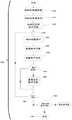
图4是监测和控制输出电压(包括其斜坡率)的控制器的功能的流程图。Figure 4 is a flow diagram of the functionality of the controller that monitors and controls the output voltage, including its ramp rate.
图5是根据自适应协议的一个示例的流程图。5 is a flow diagram according to one example of an adaptive protocol.
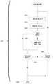
图6是根据一个示例的在自适应协议中使用的差分积分器电路。6 is a differential integrator circuit used in an adaptive protocol according to one example.
图7是根据一个示例的与电荷持续时间与频率相关的用于向自适应协议提供反馈的表格。7 is a table related to charge duration and frequency for providing feedback to an adaptive protocol, according to one example.
图8图示了在示例发明中可以用于代替图2的升压电路中的升压转换器电路的升压转换器电路。8 illustrates a boost converter circuit that may be used in place of the boost converter circuit in the boost circuit of FIG. 2 in an example invention.
图9图示了在其它示例发明中用于确定通过贴片输送给用户的电荷的电荷监测电路。9 illustrates a charge monitoring circuit used in other example inventions to determine the charge delivered to the user through the patch.
图10图示了在示例发明中用于测量施加到用户的电荷的闭环电路。Figure 10 illustrates a closed loop circuit for measuring charge applied to a user in an example invention.
图11和图12是根据示例发明的治疗监测功能的流程图。11 and 12 are flowcharts of therapy monitoring functions according to example inventions.
图13图示了根据示例发明的贴片的堆叠视图。13 illustrates a stacked view of patches according to an example invention.
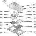
图14图示了根据示例发明的贴片组装到基板上时的堆叠视图。14 illustrates a stacked view of a patch according to an example invention when assembled onto a substrate.
图15图示了在贴片的不同示例中使用的实心和图案化电极。Figure 15 illustrates solid and patterned electrodes used in different examples of patches.
具体实施方式Detailed ways
根据本文公开的各种示例的非侵入性神经激活器包括新颖的电路系统,以将电压充分升压至所需水平并维持用于神经激活的基本恒定的电荷水平。此外,反馈回路提供了对施加的电荷水平的自动确定和适应。此外,示例通过选择性地使用电池电量来节省电池电量,并形成紧凑的电子封装以促进安装在通常小的粘性外部贴片上。Non-invasive neural activators according to various examples disclosed herein include novel circuitry to sufficiently boost voltage to desired levels and maintain a substantially constant charge level for neural activation. In addition, a feedback loop provides automatic determination and adaptation to the applied charge level. Additionally, examples conserve battery power by selectively using battery power and form a compact electronic package to facilitate mounting on typically small adhesive external patches.
图1图示了示例贴片100,其也被称为智能创可贴或智能板或局部神经激活器(“TNA”)或局部神经激活贴片,该贴片100被粘贴到用户105的踝骨110后面的位置。在图1的示例中,贴片100适于激活/刺激用户105的胫神经,并且可以具有用于左脚踝的一种形状和用于右脚踝的类似但镜像的形状。在其它示例中,将贴片100佩戴在用户105的不同位置处,以从不同位置激活胫神经或激活用户105的不同神经。FIG. 1 illustrates an
贴片100用于刺激这些神经并且是方便的、不引人注目的、自供电的,并且可以通过智能电话或其它控制设备进行控制。这具有非侵入性、由消费者自己控制以及潜在地无需处方就可以在柜台上分发的优点。贴片100提供了一种刺激神经而不穿透真皮的手段,并且可以在适合于感兴趣神经的位置处施加到真皮表面。在示例中,贴片100由用户施加并且是一次性的。The
示例中的贴片100可以是可以在一些示例中使用粘合剂被固定地贴附到用户的任何类型的设备,并且包括处理器/控制器和由处理器执行的指令,或者也可以是没有软件指令的硬件实现,以及将电刺激施加到用户皮肤表面的电极和相关联的电路系统。在一个示例中,贴片100在用户上提供局部神经激活/刺激以向用户提供益处,诸如对膀胱过度活动症(“OAB”)进行膀胱管理。The
在一个示例中,贴片100可以包括柔性基板;基板的包括粘合剂并且适于接触真皮的可延展的真皮贴合底表面;基板的大致平行于底表面的柔性顶部外表面;被定位在贴片上靠近底表面并位于顶部外表面下方并直接接触柔性基板的多个电极;嵌入在贴片中并位于顶部外表面下方并作为直接接触柔性基板的芯片上系统集成的电子电路系统(如本文公开的),该电子电路系统作为芯片上系统集成并且包括与被配置为电激活一个或多个电极的可延展的真皮贴合底表面一体的电信号发生器、耦合到电信号发生器的信号激活器、响应于对一根或多根神经的刺激而提供反馈的神经刺激传感器、被配置为与远程激活设备通信的天线、与电信号发生器电通信的电源,以及信号激活器,其中信号激活器被配置为响应于由天线接收到与激活设备的通信而激活并且电信号发生器被配置为响应于由信号激活器的激活而生成一个或多个电刺激,并且电刺激被配置为至少在贴片100附近的一个位置处刺激佩戴贴片100的用户的一根或多根神经。在题为“Topical NeurologicalStimulation”的美国专利No.10,016,600中公开了除本文公开的新颖细节之外的贴片100的示例的其它细节,该专利的公开内容通过引用并入本文。In one example,
图2是图示图1的贴片100的示例的硬件/软件相关的元件的框图。贴片100包括执行以下功能的电子电路或芯片1000:与诸如智能电话或钥匙扣(其可以使用诸如低功耗蓝牙(“BLE”)之类的无线通信与贴片100通信)的外部控制设备或诸如基于云的处理设备的外部处理进行通信、经由根据治疗方案产生大范围电场的电极1008的神经激活,以及大范围的传感器1006,诸如但不限于机械运动和压力、温度、湿度、声学、化学和定位传感器。在另一个示例中,贴片100包括换能器1014,以将信号发送到组织或从组织接收信号。FIG. 2 is a block diagram illustrating hardware/software related elements of an example of the
一种布置是将各种各样的这些功能集成到芯片上系统1000中。其中示出了用于数据处理、通信、换能器接口和存储的控制单元1002,以及连接到电极1008的一个或多个刺激器1004和传感器1006。控制单元1002可以由通用处理器/控制器、或专用处理器/控制器或专用逻辑电路来实现。合并天线1010以通过控制单元1002来用于外部通信。还包括内部电源1012,其可以是例如电池。电池的容量可以是大约1毫安至大约100毫安。其它示例可以包括外部电源。可能需要包括一个以上的芯片,以容纳用于数据处理和刺激的大范围电压,或者可以在其自己的单独芯片/电子封装上实现一种或多种功能。电子电路和芯片将经由能够传输数据和/或功率的设备内的导电轨道相互通信。One arrangement is to integrate a variety of these functions into the system-on-
贴片100解释来自控制单元1002的数据流,以从控制指令中分离出消息首部和定界符。在一个示例中,控制指令包括诸如电压水平和脉冲模式的信息。贴片100根据控制指令激活刺激器1004以生成到放置在组织上的电极1008的刺激信号。在另一个示例中,贴片100激活换能器1014以将信号发送到组织。在另一个示例中,控制指令使得从由贴片100存储的库(诸如控制单元1002内的存储库)中检索诸如电压水平和脉冲模式的信息。Tile 100 interprets the data flow from
贴片100从组织接收感觉信号,并将它们转换为由控制单元1002识别的数据流。感觉信号可以包括电、机械、声学、光学和化学信号。感觉信号由贴片100通过电极1008或从源自机械、声学、光学或化学换能器的其它输入接收。例如,来自组织的电信号通过电极1008被引入到贴片100、从模拟信号转换为数字信号,然后被插入到通过天线1010发送到外部控制设备的数据流中。在另一个示例中,声学信号由换能器1014接收、从模拟信号转换为数字信号,然后被插入到通过天线1010发送到外部控制设备的数据流中。在一些示例中,来自组织的感觉信号直接与外部控制设备接口以进行处理。
在以上公开的贴片100的示例中,当用于诸如对OAB的膀胱管理的治疗性治疗时,需要通过将电压升压至选定的水平并在激活哺乳动物的神经时提供相同水平的电荷来控制电压。此外,需要通过选择性地使用电池电量来节省电池寿命。此外,需要创建紧凑的电子封装,以促进将电子封装以普通粘合剂贴片或创可贴的尺寸范围安装在相对较小的哺乳动物皮肤贴片上。In the example of the
为了满足上述需求,示例实现了包括反馈电路和电荷施加电路的新颖升压电路。图3A是提供反馈的升压电路200的示例的电路图。To meet the above needs, the example implements a novel boost circuit including a feedback circuit and a charge application circuit. FIG. 3A is a circuit diagram of an example of a
图3B是使用升压电路200的输出的电荷施加电路300的示例的电路图。升压电路200包括电子部件和控制器/处理器270两者,该控制器/处理器270包括指令序列,这些指令一起修改由贴片100通过电极输送到用户105的外部真皮的激活/刺激的电压水平。示例中的控制器/处理器270通过图2的控制单元1002来实现。FIG. 3B is a circuit diagram of an example of the
升压电路200可以通过使用数字控制回路以从电池源创建经调节的电压,输出电压250,来代替独立的模拟控制的升压调节器。提供输出电压250作为输入电压以对施加电路300进行充电。在示例中,该电压提供通过真皮/皮肤的神经刺激电流,以为膀胱过度活动症提供治疗。在电压输出节点250处的输出电压250或“VBoost”通过控制器270使用两条数字反馈路径220、230。在这些路径中的每条路径中,控制器270使用指令序列来解释电压监视器226处的测量电压或“VADC”以及电流监视器234处测得的量或“IADC”,并确定用于准确和稳定的输出电压250的适当输出控制。The
升压电路200包括一起实现升压转换器电路210的电感器212、二极管214和电容器216。电压监测电路220包括由顶部电阻器222或“RT”、底部电阻器224或“RB”和电压监视器226形成的电阻分压器。电流监测电路230包括电流测量电阻器232或“RI”和电流监测器234。脉冲宽度调制(“PWM”)电路240包括场效应晶体管(“FET”)开关242和PWM驱动器244。输出电压250用作电能的汇(sink)。输入电压260或“VBAT”是电能的来源,并且可以由图2的电源1012来实现。The
PWM电路240改变数字方波固定频率信号内的“接通”时间,以改变命令电源开关“接通”与“断开”的时间比率。在升压电路200中,PWM驱动器244将FET开关242驱动到“接通”和“断开”状态。The
在操作中,当FET开关242接通(即导通)时,FET开关242的漏极被降至接地/GND或接地节点270。FET开关242保持接通,直到其电流达到由充当伺服控制器的控制器270选择的水平为止。该电流被测量为由电流监视器234检测到的电流测量电阻器232上的代表电压。由于电感器212的电感,能量被存储在电感器212内的磁场中。电流流过电流测量电阻器232而接地,直到FET开关242被PWM驱动器244而打开。In operation, when
当达到预期的脉冲宽度持续时间时,控制器270断开FET开关242。电感器212中的电流从FET开关242重新路由到二极管214,从而使二极管214转发电流。二极管214对电容器216进行充电。因此,在电容器216处的电压水平由控制器270来控制。When the desired pulse width duration is reached, the
使用电压监视器226和控制器270的外部伺服环路来控制输出电压250。由电阻分压器使用顶部电阻器222、底部电阻器224和电压监视器226来测量输出电压250。选择顶部电阻器222和底部电阻器224的值,以将底部电阻器224两端的电压保持在电压监视器226的监测范围内。控制器270监测来自电压监视器226的输出值。The
电荷施加电路300包括脉冲施加电路310,该脉冲施加电路310包括启用开关314。除非输出电压250在输出电压250的期望值的期望的上和下范围内,否则控制器270不允许启用开关314接通。脉冲施加电路310由控制器270通过断言启用信号/电压312或“VSW”来操作,该启用信号/电压312接通启用开关314以使由输出电压250表示的电能经由电容器316通过电极320。电容器316将电极320与充电电路中的DC电压隔离,作为设备中的安全特征。同时,控制器270继续监测输出电压250,并控制PWM驱动器244以接通和断开FET开关242,并将电容器216维持到输出电压250的期望值。The
输出电压250的稳定性可以由通过FET开关242、电流测量电阻232和电流监视器234的可选内部反馈回路来提高。控制器270以比电压监视器226上的监测更快的速率监测电流监视器234的输出值,使得在二极管214的阴极处获得的电压变化最小化,从而改善了对输出电压250的电压摆幅以及负载灵敏度的控制。The stability of
如所描述的,在示例中,控制器270使用多个反馈回路来调整PWM驱动器244的占空比,以创建跨值范围的稳定输出电压250。控制器270使用多个反馈回路和监测电路参数来控制输出电压250并评估硬件的适当功能。控制器270按照反馈和监测值起作用,以便通过禁用错误的电功能来提供改善的患者安全性和减少的电危害。As described, in the example, the
在一些示例中,控制器270用固件或软件代码来实现监测指令。在一些示例中,控制器270用硬件状态机来实现监测指令。In some examples, the
在一些示例中,电压监视器226是控制器270的内部特征。在一些示例中,电压监视器226是外部部件,其将它的数字输出值传递到控制器270的数字输入端口。In some examples, voltage monitor 226 is an internal feature of
在一些示例中,电流监视器234是控制器270的内部特征。在一些示例中,电流监视器234是外部部件,其将它的数字输出值传递到控制器270的数字输入端口。In some examples,
与已知电路相比,升压电路200的优点是减少了部件数量,这可以导致成本降低、电路板尺寸减小和可靠性更高。此外,升压电路200提供了对所有反馈数据的集中处理,这导致对故障的更快响应。此外,升压电路200控制来自VBAT260的流出电流,这增加了电池的使用寿命和可靠性。The advantage of
图4是监测和控制输出电压250(包括其斜坡率)的控制器270的功能的流程图。在一个示例中,图4和下面图5、图11和图12的流程图的功能由存储在存储器或其它计算机可读或有形介质中并由处理器执行的软件来实现。在其它示例中,功能可以由硬件执行(例如,通过使用专用集成电路(“ASIC”)、可编程门阵列(“PGA”)、现场可编程门阵列(“FPGA”)等)或硬件和软件的任何组合。FIG. 4 is a flow diagram of the function of the
FET开关242的脉冲宽度调制由一个或多个脉冲来控制,对于该一个或多个脉冲,每个脉冲宽度的设置允许或多或少的电荷作为电压通过二极管214累积在电容器216处。该脉冲宽度设置被称为斜坡强度并且在410处被初始化。控制器270使用在412处初始化的阶段索引,以预定的脉冲宽度顺序地启用每个脉冲组,每次一个阶段。期望的斜坡强度在424处被转换为脉冲宽度,这根据脉冲宽度启用和禁用FET开关242。在FET开关242为“接通”时的间隔期间,电流由电流监视器234在430处进行测量,并在436处与预期值进行核对。当电流达到预期值时,该阶段完成并且在440处递增阶段索引。如果在已经应用了期望的阶段数量442,那么该功能完成。否则,该功能在420处继续到下一个阶段。The pulse width modulation of the
由于图4的功能,贴片100中使用的VBAT 260会操作较长的时间段,因为从电池汲取的电流以较低的增长率斜升,从而减少了为实现每次激活/刺激治疗的最终电压水平250所需的峰值电流。PWM244的占空比由控制器270来调整,以改变410处的斜坡强度,从而提高电池的使用寿命。Due to the functionality of Figure 4, theVBAT 260 used in the
在已知的神经刺激设备中,用于控制流向电极的电流的开环协议没有反馈控制。其命令设置电压,但不确定输送给用户的实际电流量。刺激脉冲是根据预设参数发送的,并且通常不能基于来自患者的解剖结构的反馈进行修改。当设备被移除并重新定位时,电极的放置会发生变化。解剖结构的湿度和温度也在全天变化。如果预设了电压,那么所有这些因素都会影响实际的电荷输送。电荷控制是患者安全特征并且促进改善患者的舒适度、治疗一致性和治疗效果。In known neurostimulation devices, the open-loop protocol used to control the current flowing to the electrodes has no feedback control. Its commands set the voltage, but not the actual amount of current delivered to the user. Stimulation pulses are delivered according to preset parameters and generally cannot be modified based on feedback from the patient's anatomy. Electrode placement changes when the device is removed and repositioned. The humidity and temperature of the anatomy also vary throughout the day. All of these factors affect the actual charge transport if the voltage is preset. Charge control is a patient safety feature and promotes improved patient comfort, treatment consistency and treatment efficacy.
作为对照,贴片100的示例包括使用控制器270调节由电极320施加的电荷来解决这些缺点的特征。控制器270对刺激波形的电压进行采样,从而为自适应协议提供反馈和阻抗计算以实时修改刺激波形。使用差分积分器对由刺激波形输送到解剖结构的电流进行积分并采样,然后求和以确定输送到用户用于治疗(诸如OAB治疗)的实际电荷。在刺激事件中的每个脉冲之后,该数据将被分析并用来实时地修改后续脉冲。In contrast, examples of
这种硬件自适应允许固件协议实现自适应协议。该协议通过更改输出电压(“VBOOST”)250来调节施加到人体的电荷。治疗通过周期性脉冲序列来执行,这些周期性脉冲通过电极320将电荷输送到人体内。一些治疗的参数是固定的,而一些参数是用户可调整的。强度、持续时间和频率可以是用户可调整的。用户可以针对舒适度和功效根据需要来调整这些参数。如果有不适感,那么强度可以降低,而如果没有任何感觉,那么强度可以升高。如果最大可接受的强度导致无效的治疗,那么可以增加持续时间。This hardware adaptation allows firmware protocols to implement adaptive protocols. The protocol regulates the charge applied to the body by changing the output voltage (“VBOOST ”) 250 . Treatment is performed by a sequence of periodic pulses that deliver electrical charge through the
自适应协议adaptive protocol
图5中示出了根据以上讨论的自适应协议的一个示例的流程图。自适应协议力求在治疗期间反复且可靠地输送以库仑为单位的目标电荷(“Qtarget”),并考虑任何环境变化。因此,图5的功能是基于反馈来调整施加到用户的电荷水平,而不是使用恒定水平。A flowchart according to one example of the adaptation protocol discussed above is shown in FIG. 5 . The adaptive protocol seeks to repeatedly and reliably deliver a target charge in coulombs ("Qtarget ") during treatment, taking into account any environmental changes. Thus, the function of Figure 5 is to adjust the level of charge applied to the user based on feedback, rather than using a constant level.
该协议的数学表达式如下:The mathematical expression of the protocol is as follows:
Qtarget=Qtarget(A*dS+B*dT),其中A是在经验上确定的强度系数,dS是用户的强度变化,B是在经验上确定的持续时间系数,并且dT是用户的持续时间变化。Qtarget = Qtarget (A*dS+B*dT), where A is the empirically determined intensity factor, dS is the user's intensity change, B is the empirically determined duration factor, and dT is the user's duration Change of time.
在一个示例中,自适应协议包括两个阶段:采集阶段500和再现阶段520。用户参数的任何变化都会将自适应协议置于采集阶段。当开始第一治疗时,将基于新参数来计算新的基准电荷。在502处的新的采集阶段,丢弃了来自先前电荷施加的所有数据。在一个示例中,502指示电流使用的第一次,其中用户将贴片100放置在身体的一部分上,并且手动调整作为一系列电荷脉冲的电荷水平,直到感觉合适为止,或者随时手动或自动地改变电荷水平。然后治疗开始。该施加电荷功能的数学表达式如下:In one example, the adaptation protocol includes two phases: the
在治疗中输送的电荷为
其中T是持续时间;f是“重复率”的一种治疗(例如,赫兹或周期/秒)的脉冲计数;Qpulse(i)是在作为电压MON_CURRENT提供的治疗脉冲串中由Pulse(i)输送的测量电荷,该电压MON_CURRENT是图6中所示的差分积分器电路的结果(即,每个脉冲的平均电荷量)。图6的差分积分器电路700是用于对随时间测量的电流进行积分并对输送的电荷进行量化并因此确定在治疗脉冲上的电荷输出的电路的示例。治疗中的脉冲数量为T*f。where T is the duration; f is the "repetition rate" of pulse counts for one treatment (eg, Hertz or cycles/sec); Qpulse (i) is the pulse count in the treatment pulse train provided as voltage MON_CURRENT The measured charge delivered, the voltage MON_CURRENT, is the result of the differential integrator circuit shown in Figure 6 (ie, the average amount of charge per pulse). The
如图6中所示,MON_CURRENT 760是差分积分器电路700的结果。模数转换(“ADC”)710特征用于将电压量化成表示输送的电荷的数量。使用开尔文连接740在电极A 720和电极B 730之间测量电压。电极A 720和电极B 730连接到头座(header)750。包括了参考电压VREF 770,以保持测量结果在范围内。As shown in FIG. 6 ,
在一些示例中,模数转换710是控制器270的内部特征。在一些示例中,模数转换710是外部部件,其将它的数字输出值传递到控制器270上的数字输入端口。In some examples, analog-to-digital conversion 710 is an internal feature of
在504和506处,对每个脉冲进行采样。在一个示例中,504和506的功能以20Hz的脉冲率持续10秒,这可以被认为是完整的治疗周期。采集阶段500的结果是Qtarget的目标脉冲电荷。At 504 and 506, each pulse is sampled. In one example, the functions of 504 and 506 last for 10 seconds at a pulse rate of 20 Hz, which can be considered a complete treatment cycle. The result of
图7是根据一个示例的表格,该表格示出了针对两个参数:频率和持续时间测得的每次治疗的脉冲数量。频率被示出在Y轴上并且持续时间被示出在X轴上。一般而言,当使用更多脉冲时,自适应协议会执行得更好。一个示例使用了最少100个脉冲来提供对电荷数据反馈的可靠收敛,但是在其它示例中可以使用更少数量的脉冲。参考图7,20Hz的频率设置和10秒的持续时间产生了200个脉冲。Figure 7 is a table showing the measured number of pulses per treatment for two parameters: frequency and duration, according to one example. Frequency is shown on the Y-axis and duration is shown on the X-axis. In general, adaptive protocols perform better when more pulses are used. One example used a minimum of 100 pulses to provide reliable convergence on the charge data feedback, but in other examples a smaller number of pulses could be used. Referring to Figure 7, a frequency setting of 20 Hz and a duration of 10 seconds produced 200 pulses.
在一个示例中,当用户在采集阶段500和基准电荷的结果采集Qtarget之后发起另一个后续治疗时,再现阶段520开始。例如,如上所述,完整的治疗周期可能需要10秒钟。在例如等待时段522所示的两个小时的暂停之后,用户然后可以发起另一个治疗。在该阶段期间,自适应协议会尝试为每个后续治疗输送Qtarget。再现阶段520的功能是需要的,因为在等待时段522期间,诸如因汗水或空气湿度而引起的用户身体的阻抗的条件可能已经改变。在治疗中的每个脉冲的结束处对差分积分器进行采样。此时,开始下一个治疗,并且在524处针对每个脉冲对差分积分器进行采样,以便与采集阶段Qtarget进行比较。对脉冲采样包括依据总电荷测量脉冲的输出。图6的积分器的电压输出(被称为Mon_Current 760)与输送的电荷是直接线性关系,并提供了对有多少电荷正在离开设备并进入用户的读数。在526处,将每个单个脉冲与在采集阶段500中确定的电荷值(即目标电荷)进行比较,并且下一个脉冲将在差分的方向上进行调整。In one example, the
NUM_PULSES=(T*f)NUM_PULSES=(T*f)
在每个脉冲之后,将观察到的电荷Qpulse(i)与每个脉冲的预期电荷进行比较。After each pulse, the observed charge Qpulse (i) is compared to the expected charge for each pulse.
Qpulse(i)>Qtarget/NUM_PULSES?Qpulse (i)>Qtarget/ NUM_PULSES?
然后针对随后的脉冲通过以下公式在528处(减少)或在530处(增加)对输出电荷或“VBOOST”进行修改:The output charge or "VBOOST " is then modified at 528 (decrease) or at 530 (increase) for subsequent pulses by the following formula:
dV(i)=G[Qtarget/NUM_PULSES-Qpulse(i)]dV(i)=G[Qtarget /NUM_PULSES-Qpulse (i)]
其中G是经验上确定的电压调整系数。该处理在532处继续直到最后一个脉冲为止。where G is an empirically determined voltage adjustment factor. The process continues at 532 until the last pulse.
安全特征确保VBOOST永远不会被调高超过10%。如果需要更多电荷,那么可以增加重复率或持续时间。Safety features ensure that VBOOST is never turned up more than 10%. If more charge is required, the repetition rate or duration can be increased.
在一个示例中,升压电路使用专用电路来伺服升压电压。这些电路处理电压和/或电流测量结果,以控制升压电路的开关的PWM占空比。系统控制器可以通过调节升压电路中反馈回路的增益来设置电压。这是通过数字电位计或其它数模电路来完成的。In one example, the boost circuit uses dedicated circuitry to serve the boost voltage. These circuits process voltage and/or current measurements to control the PWM duty cycle of the boost circuit's switches. The system controller can set the voltage by adjusting the gain of the feedback loop in the boost circuit. This is done with a digital potentiometer or other digital-to-analog circuit.
在一个示例中,一般而言,在采集阶段500期间针对每个脉冲对电流进行采样以建立用于再现的目标电荷。然后,在再现阶段520期间,经由数字电位计(本文称为“电位计(Pot)”)来调整电压,以实现所建立的target_charge。In one example, in general, current is sampled for each pulse during
数字电位计在启动时用实际电压进行校准。用每个抽头(wiper)值的采样电压来生成表格。还预先计算表格,从而存储每个电位计电平下1v和5v输出差值(delta)所需的电位计抽头增量。这使得能够在再现阶段期间快速参考电压调整。由于电池电平,该表格可能需要周期性重新校准。The digital potentiometer is calibrated with the actual voltage at startup. A table is generated with the sampled voltage for each wiper value. A table is also precomputed to store the potentiometer tap increments required for the delta of the 1v and 5v outputs at each potentiometer level. This enables fast reference voltage adjustment during the reproduction phase. The table may require periodic recalibration due to battery levels.
在一个示例中,在采集阶段500期间,数据集=100个脉冲,并且对每个脉冲进行采样,并且将平均值用作再现阶段520的target_charge。一般而言,较少的脉冲提供较弱的数据样本,以用作再现阶段520的基础。In one example, during the
在一个示例中,在采集阶段500期间,最大数据集=1000个脉冲。最大值用于避免在累积样本总和时32位整数的溢出。此外,在一个示例中,1000个脉冲是足够大的数据集,并且可能不需要收集更多的脉冲。In one example, during
对于上面的示例,经过1000个脉冲之后,将计算target_charge。采集阶段中超过1000个附加脉冲对计算目标电荷没有贡献。在其它示例中,当期望更长的治疗周期时间时,最大数据集大于1000个脉冲。For the example above, after 1000 pulses, the target_charge is calculated. More than 1000 additional pulses in the acquisition phase did not contribute to the calculation of the target charge. In other examples, when longer treatment cycle times are desired, the maximum data set is greater than 1000 pulses.
在一个示例中,前3-4个脉冲通常高于其余脉冲,因此在采集阶段500中不使用这些前3-4个脉冲。在再现阶段520中也对此进行了考虑。使用这些太高的值会导致目标电荷被设置得太高,并且在再现阶段520中对后续治疗过度刺激。在其它示例中,可以应用更先进的求平均算法来消除高值和低值。In one example, the first 3-4 pulses are generally higher than the rest of the pulses, so these first 3-4 pulses are not used in the
在示例中,可能担心自动增加电压的安全问题。例如,如果设备与用户皮肤之间的连接不良,那么电压可能会在530处自动调整直到最大值。然后可能例如由于用户牢固地按压设备而阻抗减小,这可能导致突然高的电流。因此,在一个示例中,如果样本比目标高500mv或更高,那么它将立即调整到最小电压。然后,该示例保持在再现阶段520中,并且应调整回目标电流/电荷水平。在另一个示例中,为单次治疗设置了最大电压增加(例如,10V)。实现已建立的target_charge并不需要比此更多。在另一个示例中,为VBOOST设置了最大值(例如,80V)。In an example, there may be concerns about the safety of automatically increasing the voltage. For example, if the connection between the device and the user's skin is poor, the voltage may automatically adjust at 530 to a maximum value. The impedance may then decrease, for example due to the user pressing the device firmly, which may result in a sudden high current flow. So, in one example, if the sample is 500mv or more above the target, then it will immediately adjust to the minimum voltage. The sample then remains in the
在各种示例中,期望在再现阶段520期间具有稳定性。在一个示例中,这是通过逐步调整电压来实现的。但是,相对较大的步长调整可能会导致振荡或过度刺激。因此,电压调整可以以较小的步长来进行。步长尺寸可以基于目标电流和样本电流之间的差值(delta)以及实际的VBOOST电压水平。这促进快速和稳定/平滑地收敛到目标电荷,并在较低电压下使用更渐进的调整来用于更敏感的用户。In various examples, stability during the
以下是可以被评估以确定调整步长的条件。The following are conditions that can be evaluated to determine the adjustment step size.
delta-mon_current=abs(sample_mon_current-target_charge)delta-mon_current=abs(sample_mon_current-target_charge)
对于增加调整,如果delta_mon_current>500mv并且VBOOST>20V,那么步长=5VFor incremental adjustment, if delta_mon_current > 500mv and VBOOST > 20V, then step = 5V
(对于减小调整,500mv的差值会触发紧急减小到最小电压)(For reduction adjustment, a difference of 500mv will trigger emergency reduction to the minimum voltage)
如果delta_mon_current>200mv,那么步长=1VIf delta_mon_current>200mv, then step=1V
如果delta_mon_current>100mv并且delta_mon_current>5%*sample_mon_current,那么步长=1VIf delta_mon_current>100mv and delta_mon_current>5%*sample_mon_current, then step=1V
在其它示例中,以带有大约10%的电压缓冲的低于目标电压的电压开始新的治疗。在治疗开始时阻抗是未知的。这些示例在治疗结束时保存使用中的target_voltage。如果用户未手动调整强度参数,那么它将用带有10%的缓冲的保存的target_voltage开始新的治疗。这用10%的缓冲快速地实现了目标电流,从而避免了在阻抗已被降低的情况下可能的过度刺激。这也补偿了通常较高的前3-4个脉冲。In other examples, a new treatment is started with a voltage below the target voltage with a voltage buffer of approximately 10%. Impedance is unknown at the start of treatment. These examples save target_voltage in use at the end of treatment. If the intensity parameter is not manually adjusted by the user, then it will start a new treatment with the saved target_voltage with a buffer of 10%. This quickly achieves the target current with a 10% buffer, avoiding possible overstimulation if the impedance has been lowered. This also compensates for the usually higher first 3-4 pulses.
如所公开的,示例施加初始电荷水平,并且然后基于施加的电流量的反馈来自动调整。电荷量可以在施加时向上或向下变化。因此,本发明的实现不是在整个治疗周期中设置并然后施加固定的电压水平,而是测量正在输入给用户的电荷量,并在整个治疗过程中相应地进行调整以维持适合于电流环境的目标电荷水平。As disclosed, the example applies an initial charge level and then automatically adjusts based on feedback of the amount of current applied. The amount of charge can vary up or down as it is applied. Thus, rather than setting and then applying a fixed voltage level throughout the treatment cycle, implementations of the present invention measure the amount of charge being input to the user and adjust accordingly throughout the treatment to maintain a target appropriate to the current environment charge level.
以上描述的自适应电路提供了一种手段,以监测通过电极发送到用户组织的电荷,并调整发送的电荷的强度和持续时间,以便适应通过电极与皮肤界面以及通过用户组织的阻抗变化,使得在目标神经处的场强处于克服该位置处该神经动作电位并激活神经冲动所需的范围之内。这些阻抗变化可能是由于环境变化引起的,诸如皮肤或底层组织的潮湿或干燥;或由于所施加的乳液等引起的;或由于组织变化引起的,诸如皮肤干燥;或由于设备在用户皮肤上的放置的变化引起的,诸如由于移除贴片并在相对于目标神经的不同位置或朝向重新应用贴片引起的;或由于上述和其它因素的组合引起的。The adaptive circuit described above provides a means to monitor the charge sent through the electrodes to the user's tissue, and adjust the strength and duration of the sent charge to accommodate changes in impedance through the electrode-skin interface and through the user's tissue such that The field strength at the target nerve is within the range required to overcome the nerve action potential at that location and activate the nerve impulse. These impedance changes may be due to environmental changes, such as wetness or dryness of the skin or underlying tissue; or due to applied lotions, etc.; or due to tissue changes, such as dry skin; Caused by changes in placement, such as by removing the patch and reapplying the patch at a different location or orientation relative to the target nerve; or by a combination of the above and other factors.
本文公开的组合电路和电路控制生成了在随后的使用中重复的电荷。电压升压通过按需生成电压来节省电池电量。结果是有效且紧凑的电子封装,其适合安装在织物或类似材料上或之中以粘附到真皮,从而允许将电极放置在要激活的选定神经附近。The combined circuits and circuit controls disclosed herein generate a charge that is repeated in subsequent uses. Voltage boost saves battery power by generating voltage on demand. The result is an efficient and compact electronic package suitable for mounting on or in a fabric or similar material to adhere to the dermis, allowing electrodes to be placed near the selected nerve to be activated.
在一个示例中,使用两个二极管级的电压倍增器电路被添加到图2的升压电路200以使高压输出加倍或降低FET 242上的电压应力。当FET 242接通时,倍压器电路在传输电容器中累积电荷,并在FET 242断开时将电压添加到升压电路200的输出。二极管仅在正相导通,使得电压加倍。In one example, a voltage doubler circuit using two diode stages is added to the
图8图示了在示例发明中可以用于代替图2的升压电路200中的升压转换器电路210的升压转换器电路810。升压转换器电路810包括三个二极管级,添加了二极管826、828和电容器822、824。8 illustrates a
振荡器定时Oscillator Timing
在示例发明中,控制器270包括实时时钟(“RTC”)电路,该电路用于测量时间间隔,包括激活脉冲之间的时间和激活脉冲的宽度。RTC电路在控制器270上连续运行以连续实时跟踪。但是,这种连续操作会不断地消耗电池的电量。In the exemplary invention, the
在其它示例发明中,RTC电路未被使用并且被控制器270中的固件设置为非操作模式。固件使用具有已知频率的片上振荡器设置定时器,并且因此可以测量时间间隔。当贴片100连接到钥匙扣或智能控制器时,固件会使计数器清零。归零时间成为后续激活事件的初始时间。每当如由片上振荡器测量的定时器上的时间过去时,固件就调整计数器的值。固件可以向钥匙扣或智能控制器或两者报告计数器值。钥匙扣和智能控制器使用它们自己的控制器中的实时时钟通过将与计数器值和激活周期成比例的值与实时时钟值相加来计算激活时间的实时值。这允许固件避免使用片上实时时钟,从而在贴片100中节省功耗并延长电池寿命,并进一步允许钥匙扣或智能控制器计算用于贴片100激活的实时标记。这些标记对于分析贴片100的操作是有用的。片上振荡器连续运行,但比片上实时时钟消耗明显更少的电量。在示例发明中,控制器270包括32.768kHz+/-250ppm RC振荡器。当除以215时生成一秒间隔。In other example inventions, the RTC circuit is not used and is set to a non-operational mode by firmware in the
电荷输送的电流测量Current measurement of charge transport
如以上公开的,在示例发明中,由贴片100输送给用户的电荷是使用图6的差分积分器电路700来确定的。As disclosed above, in the exemplary invention, the charge delivered to the user by the
图9图示了在其它示例发明中的用于确定由贴片100输送给用户的电荷的电荷监测电路900。电路900测量到高压升压电路的电池电流。电荷监测电路900包括电流测量电阻器1142,用于向控制器270提供作为负载电流1120进入到负载中的电流随时间的测量。对升压调节器再充电所需的电荷量(如图8中所示,用于为电极产生高电压)用作测量在电极320处传递给用户的多少电荷。控制器270获取与升压调节器的电流输入成比例的测量电压MON_IBAT 1140作为输入,并且对于每个应用脉冲重复这种获取。控制器270对从每个MON_IBAT 1140测量计算的电荷求和以确定通过电流测量电阻器1142的总电荷。以类似的方式,控制器270测量电池260处的电压作为VBAT 1110。控制器270使用MON_VBAT 1130值来检查电池260是否继续输出足够的电压。电阻器1132、1144降低了测量中的噪声。9 illustrates a
与图6的差分积分器电路700相比,电流监测电路900使用更少的部件、不需要精密部件,并且在相应的印刷电路板(“PCB”)(例如,刚性基板,诸如FR-4,或柔性基板,诸如聚酰亚胺)上使用更少的空间。Compared to the
监测VBOOSTMonitor VBOOST
从贴片100从一个电极到用户,然后通过用户的组织并回到贴片100上的相对电极的连接的阻抗可能会因诸如环境湿度或皮肤干燥度而变化。随着阻抗变化,VBOOST处所需的电压将发生变化,以提供由用户选择或默认设置的电荷值,以刺激目标神经。在开环设计中,对每个刺激施加相同的VBOOST可能导致输送给用户的电荷量减少或增加,这会影响刺激的效果。它还可能影响用户的舒适度,因为皮肤会根据阻抗的变化对刺激脉冲有不同的感知。The impedance of the connection from the
作为对照,图10图示了在示例发明中使用的用于经由电极电压的测量来测量施加到用户的电荷的闭环电路1300。在闭环电路1300中,对VBOOST进行采样,并且针对输送给用户的每个刺激脉冲计算输送的电荷。By way of comparison, FIG. 10 illustrates a
电路1300包括分压器1310,分压器1310包括两个电阻器R1和R2,分压器1310用于将治疗脉冲电压1320缩放到较低范围MON_VOLTAGE 1330,以供ADC 1325采样。通过在施加的一个刺激脉冲的持续时间期间多次重复对MON_VOLTAGE 1330处的电压采样,可以获得脉冲的电压波形(即,对于单个脉冲施加给用户的在脉冲期间呈指数衰减的电压量)。The
分压器1310与用户解剖结构并联,该用户解剖结构在这个简单的电阻模型中表示为RL 1340。如静电放电协会(“ESDA”)定义的人体电容模型是与1500欧姆电阻器串联的100皮法电容器。在MON_VOLTAGE 1330处测量脉冲电压,并在脉冲持续时间内积分,然后除以RL1340的电阻,从而计算电流的积分,即总电荷。RQ1是开关晶体管1312的“导通电阻”并且应该为14欧姆或更小。开关晶体管1312将在短时间间隔内把高压VBOOST切换到电极,并在图10中示出为RQ1,并对其“导通电阻”进行建模。当没有施加脉冲时,它是开路。The
贴片100固件的固件在它们以MON_VOLTAGE 1330的采样频率作为固件循环通过ADC 1325读取时测试MON_VOLTAGE 1330的值。在每次迭代中根据MON_VOLTAGE值计算施加的电压。当施加的电压达到用户选择的水平或默认值时,开关晶体管(即,图8的开关晶体管242)接通以停止向用户施加更多电荷,因为PWM在VBOOST达到其目标时停止。如所公开的,图10是图6的替代,并且每个测量电极电流,然后确定输送给用户的电荷量。图9测量电池电流。The firmware of the
用于精细强度控制的自适应波形Adaptive waveforms for fine intensity control
示例发明中的振荡器时钟频率被选择为优化时钟电路的功耗,同时还为微控制器操作和上面公开的其它定时电路提供足够的速度。The oscillator clock frequency in the example invention is chosen to optimize the power consumption of the clock circuit while still providing sufficient speed for microcontroller operation and other timing circuits disclosed above.
PWM电路244通过改变振荡器时钟周期的计数来修改脉冲宽度。由于时钟频率有限,可能难以在PWM占空比中获得足够的分辨率来在刺激中创建足够的不同强度水平。这可能导致用户无法在太弱的一个水平和太强的下一个更高水平之间进行选择。The PWM circuit 244 modifies the pulse width by changing the count of oscillator clock cycles. Due to the limited clock frequency, it may be difficult to obtain sufficient resolution in the PWM duty cycle to create enough different intensity levels in the stimulus. This can result in the user being unable to choose between one level that is too weak and the next higher level that is too strong.
因此,在示例发明中,升压(VBOOST)的控制通过前述在PWM占空比内的水平选择,而不是在升压斜升至如由微控制器ADC读取的期望电压的时刻发起刺激而被增强以提供水平之间更高的辨别力。这实现了多得多的强度水平,其中水平之间的间隙与受由于高得多的ADC测量频率而导致的PWM分辨率限制的那些相比更小。一旦达到期望的电压阈值,向微控制器的ADC反馈就用于缩短PWM活动时间。Thus, in the exemplary invention, the boost (VBOOST ) is controlled by the aforementioned level selection within the PWM duty cycle, rather than initiating stimulation at the moment the boost ramps up to the desired voltage as read by the microcontroller ADC Enhanced to provide greater discrimination between levels. This enables much more intensity levels with smaller gaps between levels than those limited by the PWM resolution due to the much higher ADC measurement frequency. Once the desired voltage threshold is reached, feedback to the microcontroller's ADC is used to shorten the PWM active time.
除了提供更多水平的强度调整之外,通过停止升高的电压输出直到需要下一个脉冲来节省电池电量。当电池所需电流的变化率超过某个最大规格时,一些电池类型的性能较差。开始要求电池提供电流并以较慢速率增加所需电流水平的电路允许电池在若干个这样的所需电量循环中表现更好。In addition to providing more levels of intensity adjustment, battery power is conserved by stopping the boosted voltage output until the next pulse is needed. Some battery types perform poorly when the rate of change in current required by the battery exceeds a certain maximum specification. A circuit that begins to demand current from the battery and increases the required current level at a slower rate allows the battery to perform better over several such required charge cycles.
在一个示例中,PWM占空比从用于刺激的一系列脉冲中的第一个脉冲到最后一个脉冲而不同,以在刺激开始处使用较低占空比脉冲,并在刺激后期使用较高占空比脉冲。由较低占空比形成的较窄脉冲减少了对电池电路的充电需求,使得与没有占空比自适应的电路相比,电流需求开始得更慢,并继续通过刺激脉冲序列来提供更宽的脉冲和更高的电流需求,以便保持在电池的电流规格范围内,同时也升高以满足用户在他们调整强度时所需的刺激能量。In one example, the PWM duty cycle varies from the first pulse to the last pulse in a series of pulses used for stimulation to use lower duty cycle pulses at the beginning of stimulation and higher later in stimulation duty cycle pulse. The narrower pulses formed by the lower duty cycle reduce the charging demands on the battery circuit, so that the current demand starts more slowly and continues to be delivered wider by the stimulation pulse train compared to circuits without duty cycle adaptation Pulses and higher current requirements in order to stay within the battery's current specification, while also ramping up to meet the stimulation energy the user needs as they adjust the intensity.
合格的施加刺激脉冲Qualified applied stimulation pulse
电池为每个刺激脉冲提供的能量取决于贴片100中的电池类型。在施加脉冲序列的过程期间,电池的性能变化。电池性能可能会受到温度、湿度、电池使用年限和其它因素的影响。由于电池性能的这种变化,在示例发明中,大多数或每次将治疗施加于用户时调整治疗。The amount of energy the battery provides for each stimulation pulse depends on the type of battery in the
图11和图12是根据示例发明的治疗监测功能的流程图。图11涉及“正常”治疗监测处理1202,并且开始于1210处斜坡强度的初始化,以及在治疗开始之前在1212处的阶段索引的初始化,随后是1220处的正常施加循环。在1220处循环的每次迭代在1222处施加刺激脉冲、在1224处递增脉冲计数,然后在1226处测量脉冲电压。每个脉冲振幅都根据在1228处的强度设置进行测试。在示例发明中,强度水平为1-20,从而产生4V至85V的电压。未达到目标振幅的脉冲在1230处计数。“良好”脉冲计数是符合强度水平的脉冲数量,并且未达标(missed)脉冲计数是脉冲数量减去良好脉冲计数。当在1240处已施加最后一个治疗脉冲时,在1250处将未达标脉冲计数与未达标脉冲限制进行比较。11 and 12 are flowcharts of therapy monitoring functions according to example inventions. 11 refers to the "normal"
如果在图11的1250处未满足良好脉冲计数的数量,那么图12涉及“延长的”治疗监测功能1204。如果比未达标脉冲限制所允许的更多的脉冲未达标目标振幅,那么在1260处施加一个或多个延长的治疗脉冲。这些脉冲被添加到图11的原始治疗中的脉冲计数,从而延长治疗时间。当在1270处施加足够的延长治疗脉冲以满足必要强度脉冲的数量时,那么治疗完成在1290处实现。If the number of good pulse counts is not met at 1250 of FIG. 11 , then FIG. 12 refers to the “extended”
在示例发明中,目标神经刺激脉冲振幅由用户、贴片100中的固件或智能控制器中的一个或多个设置。为了至少输送治疗所需的最少脉冲数量,贴片100测量每个施加的刺激脉冲的振幅(即,电压水平)。“正常”治疗在固定时间长度内输送。未达到目标振幅的每个脉冲不计为治疗最小脉冲计数的脉冲之一。当正常治疗时间过去后,贴片100检查是否足够强脉冲数量已满足最小脉冲计数限制。如果是,那么治疗结束。如果不是,那么使用图12的功能施加附加的脉冲以完成治疗,从而延长治疗的持续时间。如果在1280处该延长超过最大治疗时间,那么即使施加的强脉冲的最小数量尚未被满足,也在治疗完成1290处停止治疗。In an example invention, the target nerve stimulation pulse amplitude is set by one or more of the user, firmware in the
贴片100记录所施加脉冲、强脉冲、治疗时间和其它参数的计数。这些收集到的数据可以被传输到智能控制器或另一个数据存储设备以供以后分析。The
固件构造Firmware Construction
如图2中所示,贴片100包括控制单元1002。控制单元1002中的特征集合用于提供对贴片100的功能的控制,是跨用于控制单元1002的特定控制芯片集合最常见的特征集合。As shown in FIG. 2 , the
当固件被设计为在每个提供的芯片上使用不同的特征集合时,在可用于构建控制单元1002的几个芯片中的每一个上提供的特征的差异导致固件复杂性的增加。这种复杂性的增加导致构建在若干芯片上的贴片100集合中固件问题的增加,并增加了需要交付给该贴片100集合的固件更新的频率。问题和更新的这种增加限制了贴片100在自己激活贴片100的那些用户子集中的功能。When the firmware is designed to use a different feature set on each provided chip, the differences in the features provided on each of the several chips available to build the
通过使用跨更大可用芯片集合兼容的特征来实现固件中的功能,在示例发明中降低了代码的复杂性、固件问题的频率和固件更新的频率。By implementing functions in firmware using features that are compatible across a larger set of available chips, the complexity of code, the frequency of firmware issues, and the frequency of firmware updates are reduced in the example invention.
在一个示例中,在可用作控制单元1002的替代方案的两个不同芯片之间,一个芯片提供中断服务,同时在一个或多个外围设备(诸如ADC)中并行执行模数转换。第二个芯片提供中断服务和ADC转换,但不能同时或并行提供。因此,贴片100固件是使用基于定时器的代码而不是基于中断的代码来实现的,使得可以在两个芯片中的任一个上执行相同的固件,从而将代码减少为一个兼容的实现。In one example, between two different chips that can be used as an alternative to the
在一个示例中,在可用作控制单元1002的替代方案的两个不同芯片之间,一个芯片提供对BLE无线通信中的许多命令类型的支持,并且第二个芯片仅提供对最低级别的BLE命令的支持。因此,贴片100的固件仅使用最低级别的BLE命令实现,诸如单写和单读命令,从而将代码减少为一种兼容的实现。In one example, between two different chips that can be used as an alternative to the
当解码通过智能控制器或钥匙扣与贴片100之间的链路接收为字节值的命令时,BLE命令编码位错误可能会在处理如由智能控制器或钥匙扣请求的功能(诸如,写回数据或读回数据),或发起或终止贴片100中的功能时导致问题或时延延迟。这些位错误有时是贴片100和智能控制器或钥匙扣之间信号质量弱的结果。这些设备之间的距离根据用户的习惯而不同。When decoding a command received as a byte value over the link between the smart controller or key fob and the
贴片100测量跨BLE的接收信号强度并将其量化为接收信号强度指示(“RSSI”)二进制值。智能控制器和/或钥匙扣使用在贴片100和智能控制器和/或钥匙扣固件中实现的一个或多个BLE命令请求这些测量值。智能控制器和/或钥匙扣将这些测量值发送到计算机或服务器或云以进行分析。分析可以将RSSI水平与命令或数据的重传率相关联,并且可以计算大量贴片100中BLE功能的统计数据。这些统计数据和相关性用于改变智能控制器、钥匙扣或贴片100的固件和/或硬件设计,以提高可靠性和响应性。The
BLE命令操作码(opcode)被设计为在贴片100接收到命令时最小化未检测到的位错误。对于具有二进制模式的每个操作码,都有具有相反二进制模式的相关操作码。避免了仅一位不同的命令操作码。The BLE command opcode is designed to minimize undetected bit errors when the
贴片的堆叠stacking of patches
图13图示了根据示例发明的贴片100的堆叠视图。底层910是在面向皮肤的一侧具有粘合剂的织物带。对于每个电极920,在底层中切出孔912。可移除纸914粘附到底层910的面向皮肤侧上的粘合剂。两个或更多个电极920通过导线922耦合到印刷电路板组件(“PCBA”)930。13 illustrates a stacked view of a
电极920被聚酰亚胺胶带A 924覆盖以防止从电极920到PCBA 930的短路并防止电极930在组件的层内移动。每个电极930在面向皮肤的表面上涂覆有水凝胶926。每个电极920具有覆盖水凝胶926的释放层。电池夹932附接到PCBA 930。电池936插入到电池夹932中。电池拉片938插入到电池夹932中。PCBA 930包裹在聚酰亚胺胶带B 934中,以限制用户接触电子器件。在面向PCBA的一侧具有粘合剂的织物胶带的顶层940堆叠在顶部以完成组装。踝骨切口942被设计为底层910和顶层940的形状以容纳踝骨并帮助用户正确放置贴片100。
水凝胶自适应Hydrogel adaptation
水凝胶926的粘度和组成的变化导致物质从其在每个电极上的原始区域迁移到更宽区域的变化,从而可能接触贴片100的尺寸之外的皮肤。随着水凝胶的迁移,其电气性能发生变化。PCBA 930上的电路系统在每次治疗期间实时测量施加到皮肤的电压。自适应电路计算输送到皮肤的电荷,其是许多参数的函数,包括水凝胶926的电导率。因此,贴片100的性能得以维持,而设备的水凝胶部分改变其性能。自适应电路调整电荷输送,以也考虑身体和皮肤电导率、汗水和贴片接触的所有变化。Changes in the viscosity and composition of the
随着水凝胶926的性能随时间降低,PCBA 930中的自适应电路和固件在特定贴片通电并且在用户皮肤上时记录其预期寿命。当贴片100确定设备的生命周期即将结束时,固件会向钥匙扣或智能控制器发信号通知,以便用户接收到该贴片已达到其限制的指示。As the performance of the
从电极到PCBA的压接连接Crimp connection from electrode to PCBA
在制造电极时,每个电极920都涂有水凝胶926。在一些示例中,当制造电极920时,导线922以永久方式,诸如通过焊接连接到电极和PCBA 930两者。电极加导线加PCBA组件各自封装在气密袋中,直到它们随后与胶带和粘合剂层组装以形成完整的贴片100。由于这些组装步骤的复杂性,电极上的水凝胶可能会暴露在空气和湿气中一段时间,这会影响水凝胶的预期寿命。As the electrodes are fabricated, each
在示例中,电极920涂有水凝胶926,但在该阶段没有附接导线。替代地,将小夹子焊接到每个电极,这不会影响水凝胶,也不会将电极附接到任何需要在组装线上花费更长时间的更大组件。这些涂敷的电极各自用热封或其它手段装在气密袋中。在涂敷的电极处于气密袋内期间,水凝胶不会降级。In the example,
在示例中,将导线922插入到先前已焊接到电极920的小夹子中,与将线束直接焊接或附接到电极920相比,这种连接更牢固并且更不容易出现缺陷。夹子和导线不影响水凝胶926。每个涂敷的电极920,连同其夹子和附接的导线,用热封或其它手段装在气密袋中。水凝胶926在涂敷电极处于密封袋内期间不会降级。涂覆的电极920仅在它们连接到PCBA930之前立即从它们的气密袋中取出。In the example, the
将涂敷电极920与PCBA 930分开作为两个不同的子组件直到放入完整的贴片100中的另一个益处是,发现有缺陷或因在货架上的时间过长而过期的涂敷电极可以被丢弃,而无需花费丢弃已经附接的PCBA。更昂贵的PCBA的保质期与涂敷电极的保质期无关。这两个子组件的库存可以独立存放、检查和管理。这降低了贴片100设备的总制造成本而不影响它们的性能。Another benefit of separating the
模切织物带Die cut fabric tape
在一些示例中,使用织物带的实心层将底层910放置为电极920上方的层。因此,贴片100的总厚度部分地由电极920上方的织物带的厚度决定。此外,为了将电极920牢固地放置在织物带层上,织物带上的纸盖必须被拉回以暴露粘合剂涂层。这导致胶带的粘合特性降级。In some examples,
在贴片100的示例中,根据那些部件的限定尺寸,切割底层910织物带以为每个电极920创建孔912。每个电极920放置在对应的孔中,顶部没有增加织物带层的厚度。由于不需要将纸盖拉回以将电极920安装到织物带,因此织物带的粘合性不受影响。可以用模具切割孔以产生准确的边缘,而没有可能干扰电极920的撕裂或纤维。In the example of the
符合踝骨轮廓Conforms to the contour of the ankle bone
在一些示例中,贴片100具有矩形形状。这允许PCBA 930、电池936和电极920装配在织物和粘合剂底层910和顶层940之间,并且由用户粘贴到皮肤,然后在使用后剥离并丢弃。在一些示例中,贴片100具有符合其将被粘贴到皮肤的位置的轮廓的形状。正确定位贴片100的参考点是脚踝或在一些示例使用中是踝骨。因此,贴片100具有沿着垂直侧的踝骨切口942,当贴片100紧靠踝骨放置时,该切口容纳踝骨。In some examples, the
在一些示例中,切口942仅在一侧被设计到贴片100中,使得电池936、PCBA 930和电极920在左脚踝或右脚踝之一上正确对齐。然后可以提供两种类型的贴片100——一种用于左脚踝,其中切口942在第一垂直侧上,另一种用于右脚踝,其中切口942在第二垂直侧上。In some examples,
在一些示例中,切口942在两个垂直侧上被设计到贴片100中,使得电池936、PCBA930和电极920在左脚踝或右脚踝中的任一个上正确对齐。贴片100然后可以只以一种类型提供。In some examples,
电池和电池拉片Batteries and Battery Pull Tabs
贴片100包括电池936,电池936被电池夹932包围,组装到PCBA 930上。在制造过程中,电池936插入到电池夹932中以固定它而防止其脱落。除了电池本身之外,电池拉片938放置在电池936的一个触点和电池夹932中的对应触点之间。电池拉片938防止电池936和电池夹932在该接触处电连接,直到电池拉片938被移除。当就位时,存在开路,使得贴片100不被激活并且在移除电池拉片938之前不消耗电量。
在一些示例中,电池拉片938被设计为通过沿着与电池936插入电池夹932中的方向相反的方向将其拉出而被移除。这种拉动动作可能导致电池本身移动,因为它会受到朝电池夹932开口侧的拉力。这种电池移动可能导致贴片100停止操作或永远不会激活。In some examples, the
在一个示例中,电池拉片938和电池夹932被设计为使得电池拉片938在与电池936被推入到电池夹932中相同的方向上被拉出。因此,将电池拉片938拉出贴片100的力仅用于使电池936在其电池夹932中更加牢固。这减少了电池936无意移动的机会以及对贴片100的激活或操作的影响。In one example,
电极离型膜Electrode release film
组装的贴片100中的每个电极920都覆盖有聚对苯二甲酸乙二醇酯(“PET”)硅覆盖的离型膜926。当贴片100粘贴到皮肤时,离型膜被用户拉开。在一些示例中,PET硅覆盖的离型膜926是透明的。当用户可能无法确定胶带是否已被移除时,这可能导致用户方面混淆的情况。将贴片100粘贴到皮肤并且任何一个电极920仍被胶带覆盖将导致贴片100无效。这种无效性可能直到第一次使用贴片100治疗时才会注意到。如果在用户有尿急的感觉时发现粘贴的贴片100无效,那么用户可能难以正确排尿或移除贴片100、从电极上剥下胶带或粘贴新贴片100并用重新粘贴的或新的设备抑制尿急。Each
在示例中,覆盖电极920的PET硅覆盖离型膜926被选择为对用户显眼的颜色,使得用户将容易确定胶带是否已被移除。In an example, the PET silicon covered
示例使用电路系统和固件在贴片100最初被激活时以简短的低能量脉冲或脉冲序列来刺激电极电路。如果贴片100在粘贴到皮肤之前被激活,那么电极就绪测试将失败。在这种情况下,电极就绪测试根据固件或硬件中的定时器一次又一次地重复,直到或者定时器全部到期或者测试通过。当发现贴片100表现出适合其设计的电路性能时,测试通过。当贴片100未正确准备时,诸如未移除电极膜,或在定时器全部到期时尚未施加到皮肤,测试失败。当电极就绪测试失败时,贴片100向钥匙扣或智能控制器发信号通知,钥匙扣或智能控制器进而通知用户。电极就绪测试以用户可能无法检测到的方式实现,并最大限度地减少测试对电池电量的使用。The example uses circuitry and firmware to stimulate the electrode circuitry with brief low energy pulses or pulse trains when the
可移除纸removable paper
在一些示例中,可移除纸914覆盖底层910的粘合剂侧。可移除纸914可以是多个部分,当贴片100粘贴到皮肤时,每个部分都被用户拉开。这些可移除纸可以是覆盖每个电极920的PET膜926的片的补充。因此,在示例中,用户必须移除所有这些片以暴露完整的粘性表面来固定到皮肤。In some examples,
在示例中,底层910是一个完整的片,具有一个可移除纸914。用户在一个动作中移除所有可移除纸。在示例中,底层910是两片或更多片,具有两个或更多个可移除纸914。用户移除所有可移除纸。在示例中,单个可移除纸914被设计有拉片,以便用户在与贴片100的长轴成直角的方向上将可移除纸从底层拉出。这种运动减少了贴片100的组装的内部部件所承受的力。In the example, the
在示例中,可移除纸914覆盖底层910并且覆盖所有PET膜部分926。粘合剂将可移除纸顶表面附接到聚酰亚胺胶带A面向皮肤的表面,使得用户将可移除纸从底层拉出并且在一个动作中从电极920移除PET膜片。In an example, the
还可以通过在顶层和底层之间添加材料,诸如可以缓冲电极和电子部件的缓冲材料,使贴片100更加舒适。在贴片100的至少一部分中,缓冲材料可以设置在底层之下和顶层之上。缓冲材料可以包括纤维素纤维(例如,木浆纤维)、其它天然纤维、合成纤维、机织或非织造片材、稀松布网或其它稳定结构、超吸收材料、泡沫、粘结剂材料等,以及其组合。
水凝胶与电极边缘重叠The hydrogel overlaps the electrode edge
在一些示例中,每个电极920都覆盖有水凝胶926,水凝胶926符合电极920的尺寸,使得当贴片100施加到皮肤时,电极920的边缘暴露于用户的皮肤。在贴片100粘贴到皮肤的过程中,该边缘可能会磨损或切割用户的皮肤。In some examples, each
在一些示例中,水凝胶926的尺寸被设计为与电极920的边缘重叠。水凝胶926以制造中使用的放置准确度放置在电极920上,使得电极920的边缘总是被水凝胶926覆盖。这防止边缘电极920接触用户的皮肤。因此消除了电极920磨损或切割用户皮肤的风险。In some examples, the
图14图示了根据示例发明的贴片100组装到基板950上时的堆叠视图。电池936直接或经由电池夹粘贴到基板950,并使用电镀在基板950上的两个或更多个导电路径连接到电子器件。电极920使用通孔942连接到电压和地,从而形成从基板950的顶表面到底表面的电路径。顶层940粘贴在电池936上以限制用户对电子器件的访问。FIG. 14 illustrates a stacked view of the
可以选择电极920之间的距离以最大化目标神经处的电信号的有效性和/或最小化贴片100的占用面积。每个电极920可以具有从大约500mm2至大约1100mm2的面向身体的表面面积。电极920可以具有不同或相同的面向身体的表面面积。电极920的面向身体的表面面积的总和可以小于3,000mm2,优选地从大约1050mm2至大约2200mm2,更优选地从大约500mm2至2200mm2。The distance between
电极920可以间隔开大约1mm至大约100mm(边缘到边缘),优选地间隔开大约5mm至大约80mm,更优选地间隔开大约10mm至大约60mm。电极920之间的距离可以被选择为最大化目标神经处的电信号的有效性和/或最小化神经刺激设备的占用面积。替代地,贴片100可以包括电极阵列。此外,如图14中所示,电极920由相对窄的峡部925间隔开。峡部925提供电极920的分离以增强性能,并且在贴片100的长时间使用期间提供增强的佩戴舒适度并减少磨损,特别是当贴片100放置在脚踝上时。此外,峡部925减轻了电路与电池或其它部件之间的应力和引线断裂。The
电极中的矩阵图案Matrix pattern in electrodes
图15图示了在贴片100的不同示例中使用的实心和图案化电极。在示例中,两个电极920中的每一个作为连续区域被电镀到基板层上,如图14和图15A中所示。FIG. 15 illustrates solid and patterned electrodes used in different examples of
在一个示例中,两个电极920中的每一个被电镀成矩阵图案,如图15B中所示,使得每个电极的表面是平面的。没有使用连续电镀区域时看到的波纹,并且电极相对用户的皮肤平放。矩阵的每个元件都连接到由激活电压驱动的公共电结点,使得激活电压同时被驱动到矩阵的所有元件。In one example, each of the two
在一个示例中,两个电极920中的每一个被电镀成条状图案,如图15C中所示,使得每个电极的表面是平面的。条纹图案的每个元件都连接到由激活电压驱动的公共电结点,使得激活电压同时被驱动到矩阵的所有元件。公共电结点可以在与外电镀层分开的PCB层中,或者可以通过围绕其周边连接条纹或在中点处从条纹到条纹连接来形成结点。In one example, each of the two
在一个示例中,印刷电路板组件(“PCBA”)930(例如,使用PCB的一侧或两侧,无论是刚性的还是柔性的,用于导电路径的电镀和电子部件的安装)组装到柔性基板而不是刚性基板上,如图14中所示,使得没有使用刚性基板时看到的波纹,并且PCBA相对用户的皮肤平放。In one example, a printed circuit board assembly ("PCBA") 930 (eg, using one or both sides of a PCB, whether rigid or flexible, for electroplating of conductive paths and mounting of electronic components) is assembled to a flexible On a substrate rather than a rigid substrate, as shown in Figure 14, so that there is no corrugation seen when a rigid substrate is used, and the PCBA lies flat against the user's skin.
计算矩阵或条纹形式的电极的总面积以在用户的皮肤上提供足够的覆盖,以允许在神经激活的目标位置上放置电极的变化,使得即使贴片100被放置从最佳位置偏离中心,电极也延伸穿过目标区域足以输送有效刺激。The total area of electrodes in matrix or stripe form is calculated to provide sufficient coverage on the user's skin to allow for variations in electrode placement at the target location for neural activation such that even if the
在示例发明中,一层水凝胶926涂覆每个电极920。虽然电极920被电镀成矩阵或条纹或类似图案,但水凝胶是跨两个电极中的每个电极的连续区域。这种连续的导电表面将施加的脉冲电压分布在整个皮肤区域,以避免干扰皮肤的表面。In the exemplary invention, a layer of
电路部件的保护Protection of circuit components
该层水凝胶926涂敷PCBA 930的电极侧。通孔用于从PCB的顶表面连接到底表面,从而为诸如SOC 1000之类的部件中的一个或多个部件提供电连接。在使用贴片100期间,水凝胶可以通过通孔中的一个或多个迁移到PCB的顶表面。这种具有导电性的迁移材料可能干扰PCB的顶表面上的一个或多个电部件的性能,诸如导致此类部件(例如SOC 1000)的一个或多个引脚上的接地短路或其它电压短路。This layer of
PCB被制造为具有覆盖一个或多个通孔的层,该层被粘贴到PCB的底侧。在通孔上施加覆盖层之后,水凝胶926被涂敷到PCB的底侧。覆盖层防止水凝胶或其它污染物(诸如,水)进入和/或通过通孔侵入和/或迁移,从而形成永久性屏障,使得贴片100的功能通过用户的重复使用得以维持。该覆盖层还防止从制造到用户初次使用期间的侵入和迁移,从而确保贴片100的保质期。The PCB is fabricated with a layer covering one or more vias that is glued to the bottom side of the PCB. After the capping layer is applied over the vias, the
水凝胶阻抗Hydrogel impedance
执行刺激所需的电量与施加的电压和电极920通过水凝胶926和用户皮肤看到的阻抗相关。当水凝胶具有较高阻抗时,需要更多的电量来执行刺激。利用从贴片100中的电池936可获得的固定电量,这种每次刺激的能量对可以施加的刺激的数量设置了限制。The amount of electricity required to perform stimulation is related to the voltage applied and the impedance seen by the
在一个示例中,选择了具有较低阻抗的水凝胶926以允许在电路中消耗更少的能量,以及使用电池936的每个贴片100的更多的刺激。水凝胶的阻抗可以通过以下一种或多种方法来最小化:减少水凝胶涂敷厚度、改变材料成分,以及增加涂敷在电极920上的水凝胶的尺寸,甚至延伸超过电极边界到PCBA 930的底表面上。In one example, the
本文具体图示和/或描述了几个示例。但是,将认识到的是,在不脱离本发明的精神和预期范围的情况下,以上教导涵盖了所公开示例的修改和变化并且这些修改和变化在所附权利要求的范围内。Several examples are specifically illustrated and/or described herein. It will be appreciated, however, that modifications and variations of the disclosed examples are covered by the above teachings and are within the scope of the appended claims without departing from the spirit and intended scope of the invention.
Claims (20)
Applications Claiming Priority (3)
| Application Number | Priority Date | Filing Date | Title |
|---|---|---|---|
| US201962948780P | 2019-12-16 | 2019-12-16 | |
| US62/948,780 | 2019-12-16 | ||
| PCT/US2020/065235WO2021126921A1 (en) | 2019-12-16 | 2020-12-16 | Non-invasive nerve activator with boosted charge delivery |
Publications (1)
| Publication Number | Publication Date |
|---|---|
| CN114728161Atrue CN114728161A (en) | 2022-07-08 |
Family
ID=76316141
Family Applications (1)
| Application Number | Title | Priority Date | Filing Date |
|---|---|---|---|
| CN202080075757.0APendingCN114728161A (en) | 2019-12-16 | 2020-12-16 | Non-invasive neural activator with boosted charge delivery |
Country Status (7)
| Country | Link |
|---|---|
| US (1) | US11730958B2 (en) |
| EP (1) | EP4017580A4 (en) |
| JP (1) | JP2023506713A (en) |
| KR (1) | KR20220115802A (en) |
| CN (1) | CN114728161A (en) |
| CA (1) | CA3152451A1 (en) |
| WO (1) | WO2021126921A1 (en) |
Families Citing this family (1)
| Publication number | Priority date | Publication date | Assignee | Title |
|---|---|---|---|---|
| US11806306B1 (en)* | 2023-03-01 | 2023-11-07 | Xuebin Guo | Surround pinch-kneading massager |
Citations (14)
| Publication number | Priority date | Publication date | Assignee | Title |
|---|---|---|---|---|
| GB1482603A (en)* | 1973-08-10 | 1977-08-10 | Data General Corp | Data processing system |
| CN1070522A (en)* | 1991-09-10 | 1993-03-31 | 约翰弗兰克制造公司 | Lower the method and apparatus of PLL noise |
| CA2132157A1 (en)* | 1994-09-15 | 1996-03-16 | Jozef Cywinski | Device for Trophic Stimulation of Muscles |
| US5522866A (en)* | 1994-11-01 | 1996-06-04 | Intermedics, Inc. | Method and apparatus for improving the resolution of pulse position modulated communications between an implantable medical device and an external medical device |
| US20080021519A1 (en)* | 2004-05-28 | 2008-01-24 | Jan De Geest | Communication Unit for a Person's Skin |
| US20100312188A1 (en)* | 2008-12-15 | 2010-12-09 | Timothy Robertson | Body-Associated Receiver and Method |
| EP2486953A1 (en)* | 2011-02-09 | 2012-08-15 | Sorin CRM SAS | Method for quantifying the desynchronisation between the clocks of two active HBC implants |
| US20130013022A1 (en)* | 2010-03-19 | 2013-01-10 | De Oliveira Barroso Junior Ubirajara | Enuresis Electroconditioner |
| US20150202436A1 (en)* | 2014-01-17 | 2015-07-23 | Medtronic, Inc. | Cardiac resynchronization therapy optimization based on intracardiac impedance |
| US20160278658A1 (en)* | 2013-09-25 | 2016-09-29 | Bardy Diagnostics, Inc. | Wearable Electrocardiography And Physiology Monitoring Ensemble |
| US20160331952A1 (en)* | 2009-11-17 | 2016-11-17 | Michael A. Faltys | External programmer |
| CN107029349A (en)* | 2012-03-09 | 2017-08-11 | 安特罗麦迪克斯公司 | Safety feature in Medical Devices |
| US20190134391A1 (en)* | 2017-11-07 | 2019-05-09 | Neurostim Oab, Inc. | Non-Invasive Nerve Activator with Adaptive Circuit |
| US20190336763A1 (en)* | 2013-05-30 | 2019-11-07 | Neurostim Oab, Inc. | Neuro Activator with Controller |
Family Cites Families (1010)
| Publication number | Priority date | Publication date | Assignee | Title |
|---|---|---|---|---|
| US4277980A (en) | 1979-03-12 | 1981-07-14 | Reine H. Pendleton | Apparatus and method for indicating sound levels |
| US4690144A (en) | 1982-04-02 | 1987-09-01 | Medtronic, Inc. | Wireless transcutaneous electrical tissue stimulator |
| US4549556A (en) | 1982-12-08 | 1985-10-29 | Cordis Corporation | Implantable lead |
| US4542753A (en) | 1982-12-22 | 1985-09-24 | Biosonics, Inc. | Apparatus and method for stimulating penile erectile tissue |
| US4532930A (en) | 1983-04-11 | 1985-08-06 | Commonwealth Of Australia, Dept. Of Science & Technology | Cochlear implant system for an auditory prosthesis |
| US4702254A (en) | 1983-09-14 | 1987-10-27 | Jacob Zabara | Neurocybernetic prosthesis |
| US4800898A (en) | 1983-10-07 | 1989-01-31 | Cordis Corporation | Neural stimulator electrode element and lead |
| US4553549A (en) | 1984-10-09 | 1985-11-19 | Pope Bryan M | Oral orthopedic/orthodontic appliance for treating neuromuscular imbalance |
| US4590949A (en) | 1984-11-01 | 1986-05-27 | Cordis Corporation | Neural stimulating lead with stabilizing mechanism and method for using same |
| US4614395A (en) | 1985-04-04 | 1986-09-30 | Cordis Corporation | Quick connector to medical electrical lead |
| US4658835A (en) | 1985-07-25 | 1987-04-21 | Cordis Corporation | Neural stimulating lead with fixation canopy formation |
| US4706682A (en) | 1985-08-21 | 1987-11-17 | Minnesota Mining And Manufacturing Company | External ear canal electrode to be placed proximate the tympanic membrane |
| US4817628A (en) | 1985-10-18 | 1989-04-04 | David L. Zealear | System and method for evaluating neurological function controlling muscular movements |
| US5089862A (en) | 1986-05-12 | 1992-02-18 | Warner Jr Raymond M | Monocrystalline three-dimensional integrated circuit |
| US4677989A (en) | 1986-02-06 | 1987-07-07 | Eic Laboratories, Inc. | Iridium oxide coated electrodes for neural stimulation |
| US4717581A (en) | 1986-02-06 | 1988-01-05 | Eic Laboratories, Inc. | Iridium oxide coated electrodes for neural stimulation |
| US4759228A (en) | 1987-01-09 | 1988-07-26 | International Flavors & Fragrances Inc. | Process for determination of repellency and attractancy |
| US4940453A (en) | 1987-01-28 | 1990-07-10 | Cadwell Industries, Inc. | Method and apparatus for magnetically stimulating neurons |
| US5047005A (en) | 1987-01-28 | 1991-09-10 | Cadwell Industries, Inc. | Method and apparatus for magnetically stimulating neurons |
| US4883666A (en) | 1987-04-29 | 1989-11-28 | Massachusetts Institute Of Technology | Controlled drug delivery system for treatment of neural disorders |
| US4881526A (en) | 1988-05-27 | 1989-11-21 | Empi, Inc. | Intravaginal electrode and stimulation system for controlling female urinary incontinence |
| US4919148A (en) | 1988-06-13 | 1990-04-24 | Muccio Philip E | Apparatus and method for transcutaneous electrical stimulation |
| US5211657A (en) | 1988-11-07 | 1993-05-18 | The United States Government As Represented By The Secretary Of The Department Of Health And Human Services | Laminin a chain deduced amino acid sequence, expression vectors and active synthetic peptides |
| US4959532A (en) | 1989-02-16 | 1990-09-25 | Hughes Aircraft Company | Optical neural network and method |
| FR2646779B1 (en) | 1989-05-10 | 1993-07-09 | Vincent Jean | TRANSCUTANEOUS NEUROSTIMULATION DEVICE FOR THE TREATMENT OF PAIN |
| US5876425A (en) | 1989-09-22 | 1999-03-02 | Advanced Bionics Corporation | Power control loop for implantable tissue stimulator |
| US5569307A (en) | 1989-09-22 | 1996-10-29 | Alfred E. Mann Foundation For Scientific Research | Implantable cochlear stimulator having backtelemetry handshake signal |
| US5603726A (en) | 1989-09-22 | 1997-02-18 | Alfred E. Mann Foundation For Scientific Research | Multichannel cochlear implant system including wearable speech processor |
| US5938691A (en) | 1989-09-22 | 1999-08-17 | Alfred E. Mann Foundation | Multichannel implantable cochlear stimulator |
| US5031621A (en) | 1989-12-06 | 1991-07-16 | Grandjean Pierre A | Nerve electrode with biological substrate |
| US5092332A (en) | 1990-02-22 | 1992-03-03 | Medtronic, Inc. | Steroid eluting cuff electrode for peripheral nerve stimulation |
| US5265608A (en) | 1990-02-22 | 1993-11-30 | Medtronic, Inc. | Steroid eluting electrode for peripheral nerve stimulation |
| US5035242A (en) | 1990-04-16 | 1991-07-30 | David Franklin | Method and apparatus for sound responsive tactile stimulation of deaf individuals |
| US5095905A (en) | 1990-06-07 | 1992-03-17 | Medtronic, Inc. | Implantable neural electrode |
| US5092835A (en) | 1990-07-06 | 1992-03-03 | Schurig Janet L S | Brain and nerve healing power apparatus and method |
| US5618531A (en) | 1990-10-19 | 1997-04-08 | New York University | Method for increasing the viability of cells which are administered to the brain or spinal cord |
| US6800603B2 (en) | 1991-03-11 | 2004-10-05 | Curis, Inc. | Morphogen-induced neural cell adhesion |
| JPH07507441A (en) | 1991-11-01 | 1995-08-24 | ジヨスリン・ダイアビーテイス・センター | Antigens associated with type 1 diabetes mellitus |
| US5853370A (en) | 1996-09-13 | 1998-12-29 | Non-Invasive Technology, Inc. | Optical system and method for non-invasive imaging of biological tissue |
| US5476494A (en) | 1992-09-11 | 1995-12-19 | Massachusetts Institute Of Technology | Low pressure neural contact structure |
| US5766948A (en) | 1993-01-06 | 1998-06-16 | The Regents Of The University Of California | Method for production of neuroblasts |
| US5869337A (en) | 1993-02-12 | 1999-02-09 | President And Fellows Of Harvard College | Regulated transcription of targeted genes and other biological events |
| US5597381A (en) | 1993-06-03 | 1997-01-28 | Massachusetts Eye And Ear Infirmary | Methods for epi-retinal implantation |
| GB2278783A (en) | 1993-06-11 | 1994-12-14 | Daniel Shellon Gluck | Method of magnetically stimulating neural cells |
| US5381801A (en) | 1993-08-17 | 1995-01-17 | Mcshane; Jerry M. | Electromechanical tactile stimulation device worn on a belt for the prevention of snoring |
| US5501703A (en) | 1994-01-24 | 1996-03-26 | Medtronic, Inc. | Multichannel apparatus for epidural spinal cord stimulator |
| US5679340A (en) | 1994-03-31 | 1997-10-21 | Diacrin, Inc. | Cells with multiple altered epitopes on a surface antigen for use in transplantation |
| US20060140930A1 (en) | 1994-04-29 | 2006-06-29 | Mayo Foundation For Medical Research | Promotion of central nervous system remyelination using monoclonal autoantibodies |
| US5563067A (en) | 1994-06-13 | 1996-10-08 | Matsushita Electric Industrial Co., Ltd. | Cell potential measurement apparatus having a plurality of microelectrodes |
| USRE40209E1 (en) | 1994-06-13 | 2008-04-01 | Matsushita Electric Industrial Co., Ltd. | Cell potential measurement apparatus having a plurality of microelectrodes |
| US5840576A (en) | 1994-07-20 | 1998-11-24 | Cytotherapeutics, Inc. | Methods and compositions of growth control for cells encapsulated within bioartificial organs |
| US5628769A (en) | 1994-09-30 | 1997-05-13 | Saringer Research, Inc. | Method and devices for producing somatosensory stimulation using temperature |
| US5629194A (en) | 1994-10-21 | 1997-05-13 | Diacrin, Inc. | Isolated porcine pancreatic cells for use in treatment of diseases characterized by insufficient insulin activity |
| US6294383B1 (en) | 1994-11-08 | 2001-09-25 | The Mclean Hospital Corporation | Porcine neural cells and their use in treatment of neurological deficits due to neurodegenerative diseases |
| US6277372B1 (en) | 1994-11-08 | 2001-08-21 | Diacrin, Inc. | Porcine neural cells and their use in treatment of neurological deficits due to neurodegenerative diseases |
| US6204053B1 (en) | 1994-11-08 | 2001-03-20 | Diacrin, Inc. | Porcine cortical cells and their use in treatment of neurological deficits due to neurodegenerative diseases |
| US5584869A (en) | 1995-02-13 | 1996-12-17 | Advanced Bionics Corporation | Failure detection in auditory response stimulators |
| US5830651A (en) | 1995-06-01 | 1998-11-03 | Signal Pharmaceuticals, Inc. | Human oligodendroglial progenitor cell line |
| US5992769A (en) | 1995-06-09 | 1999-11-30 | The Regents Of The University Of Michigan | Microchannel system for fluid delivery |
| JP2930181B2 (en) | 1995-06-20 | 1999-08-03 | 松下電器産業株式会社 | Two-dimensional sensor for measuring nerve cell activity and measuring device using the same |
| DE69633336T2 (en) | 1995-06-27 | 2005-09-22 | Research Foundation Of Cuny | COMPOSITION CONTAINING AN INHIBITOR OF MYELIN-ASSOCIATED GLYCOPROTEIN (MAG), WHICH CONTAINS A CHANGED OR MUTED FORM OF MAG |
| JP2917270B2 (en) | 1995-08-04 | 1999-07-12 | 東洋産業株式会社 | Low frequency treatment device |
| US5800530A (en) | 1995-08-18 | 1998-09-01 | Rizzo, Iii; Joseph | Intra-ocular lens system including microelectric components |
| AU708422B2 (en) | 1995-10-19 | 1999-08-05 | Cochlear Pty. Limited | Embedded data link and protocol |
| US5965125A (en) | 1995-10-25 | 1999-10-12 | Transkaryotic Therapies, Inc. | Hybrid matrix implants and explants |
| US6048964A (en) | 1995-12-12 | 2000-04-11 | Stryker Corporation | Compositions and therapeutic methods using morphogenic proteins and stimulatory factors |
| US20040064052A1 (en) | 1996-01-02 | 2004-04-01 | Britton Chance | Non-invasive imaging of biological tissue |
| CA2171067A1 (en) | 1996-03-05 | 1997-09-06 | Brian J. Andrews | Neural prosthesis |
| US5824022A (en) | 1996-03-07 | 1998-10-20 | Advanced Bionics Corporation | Cochlear stimulation system employing behind-the-ear speech processor with remote control |
| EP0929341B1 (en) | 1996-03-07 | 2005-08-24 | Axon Engineering, Inc. | Polymer-metal foil structure for neural stimulating electrodes |
| US5792209A (en) | 1996-04-01 | 1998-08-11 | Varner; Lawrence Norman | Osteoporosis-relief device |
| US5713922A (en) | 1996-04-25 | 1998-02-03 | Medtronic, Inc. | Techniques for adjusting the locus of excitation of neural tissue in the spinal cord or brain |
| US6060054A (en) | 1996-04-10 | 2000-05-09 | National Jewish Medical And Research Center | Product for T lymphocyte immunosuppression |
| EP0906138A1 (en) | 1996-04-26 | 1999-04-07 | Zentralinstitut für Biomedizinische Technik der Universität Ulm | Method and apparatus for focused neuromagnetic stimulation and detection |
| US5921245A (en) | 1996-06-03 | 1999-07-13 | O'donnell, Jr.; Francis E. | Method for modification of anti-social behavior |
| AU3582197A (en) | 1996-06-28 | 1998-01-21 | Battelle Memorial Institute | Edge effect compensating bar code reader |
| US6002960A (en) | 1996-08-27 | 1999-12-14 | The Johns Hopkins University | Passive, non-invasive method to quantify objectively the level and density of a neural blockade |
| US8734339B2 (en) | 1996-12-16 | 2014-05-27 | Ip Holdings, Inc. | Electronic skin patch for real time monitoring of cardiac activity and personal health management |
| US6148233A (en) | 1997-03-07 | 2000-11-14 | Cardiac Science, Inc. | Defibrillation system having segmented electrodes |
| EP0866592A3 (en) | 1997-03-20 | 1999-06-16 | Nortel Networks Corporation | Personal communication device and call process status signalling method |
| US6085115A (en) | 1997-05-22 | 2000-07-04 | Massachusetts Institite Of Technology | Biopotential measurement including electroporation of tissue surface |
| ES2224420T3 (en) | 1997-08-01 | 2005-03-01 | Alfred E. Mann Foundation For Scientific Research | IMPLANTABLE DEVICE WITH IMPROVED POWER AND BATTERY RECHARGE CONFIGURATION. |
| AU9024198A (en) | 1997-08-19 | 1999-03-08 | Vanderbilt University | Methods for determining cell responses through ephb receptors |
| US6016449A (en) | 1997-10-27 | 2000-01-18 | Neuropace, Inc. | System for treatment of neurological disorders |
| US20020034819A1 (en) | 1998-02-23 | 2002-03-21 | Alan K. Smith | Human lineage committed cell composition with enhanced proliferative potential, biological effector function, or both; methods for obtaining same; and their uses |
| US6727696B2 (en) | 1998-03-06 | 2004-04-27 | Baker Hughes Incorporated | Downhole NMR processing |
| US6094599A (en) | 1998-03-24 | 2000-07-25 | Ehti Medical Corporation | RF diathermy and faradic muscle stimulation treatment |
| US6058331A (en) | 1998-04-27 | 2000-05-02 | Medtronic, Inc. | Apparatus and method for treating peripheral vascular disease and organ ischemia by electrical stimulation with closed loop feedback control |
| US6374140B1 (en) | 1998-04-30 | 2002-04-16 | Medtronic, Inc. | Method and apparatus for treating seizure disorders by stimulating the olfactory senses |
| US6270831B2 (en) | 1998-04-30 | 2001-08-07 | Medquest Products, Inc. | Method and apparatus for providing a conductive, amorphous non-stick coating |
| US6319241B1 (en) | 1998-04-30 | 2001-11-20 | Medtronic, Inc. | Techniques for positioning therapy delivery elements within a spinal cord or a brain |
| US6421566B1 (en) | 1998-04-30 | 2002-07-16 | Medtronic, Inc. | Selective dorsal column stimulation in SCS, using conditioning pulses |
| US6610917B2 (en) | 1998-05-15 | 2003-08-26 | Lester F. Ludwig | Activity indication, external source, and processing loop provisions for driven vibrating-element environments |
| US20020136705A1 (en) | 1998-06-30 | 2002-09-26 | Jonathan Dinsmore | Porcine spinal cord cells and their use in spinal cord repair |
| US5871534A (en) | 1998-07-08 | 1999-02-16 | Messick; Genevieve M. | Apparatus for treating pelvic floor dysfunctions using transcutaneous electrical stimulation of the muscles |
| US9320900B2 (en) | 1998-08-05 | 2016-04-26 | Cyberonics, Inc. | Methods and systems for determining subject-specific parameters for a neuromodulation therapy |
| US7599736B2 (en) | 2001-07-23 | 2009-10-06 | Dilorenzo Biomedical, Llc | Method and apparatus for neuromodulation and physiologic modulation for the treatment of metabolic and neuropsychiatric disease |
| US7209787B2 (en) | 1998-08-05 | 2007-04-24 | Bioneuronics Corporation | Apparatus and method for closed-loop intracranial stimulation for optimal control of neurological disease |
| US6284245B1 (en) | 1998-08-25 | 2001-09-04 | Diacrin, Inc. | Neural retinal cells and retinal pigment epithelium cells and their use in treatment of retinal disorders |
| US6304787B1 (en) | 1998-08-26 | 2001-10-16 | Advanced Bionics Corporation | Cochlear electrode array having current-focusing and tissue-treating features |
| IL141755A0 (en) | 1998-09-04 | 2002-03-10 | Wolfe Res Pty Ltd | Medical implant system |
| US6379393B1 (en) | 1998-09-14 | 2002-04-30 | Rutgers, The State University Of New Jersey | Prosthetic, orthotic, and other rehabilitative robotic assistive devices actuated by smart materials |
| US6444205B2 (en) | 1998-09-30 | 2002-09-03 | Diacrin, Inc. | Transplantation of neural cells for the treatment of chronic pain or spasticity |
| US20020041987A1 (en) | 1998-10-23 | 2002-04-11 | Joseph H. Schulman | Prismatic zincair battery for use with biological stimulator |
| CA2359816C (en) | 1999-01-06 | 2010-08-03 | Genenews Inc. | Method for the detection of gene transcripts in blood and uses thereof |
| US8180453B2 (en) | 1999-03-24 | 2012-05-15 | Second Sight Medical Products, Inc. | Electrode array for neural stimulation |
| JP5021119B2 (en) | 1999-03-24 | 2012-09-05 | セカンド サイト メディカル プロダクツ インコーポレイテッド | Retina artificial color prosthesis for color vision recovery |
| US6178349B1 (en) | 1999-04-15 | 2001-01-23 | Medtronic, Inc. | Drug delivery neural stimulation device for treatment of cardiovascular disorders |
| AUPQ047899A0 (en) | 1999-05-21 | 1999-06-10 | Cooke, Michael | A device for use with computer games |
| GB9911878D0 (en) | 1999-05-22 | 1999-07-21 | Marconi Electronic Syst Ltd | Identification tag |
| US7101542B1 (en) | 1999-05-26 | 2006-09-05 | Vallera Daniel A | Cell-mediated targeting of toxins to pathogenic cells |
| US8921473B1 (en) | 2004-04-30 | 2014-12-30 | Sydney Hyman | Image making medium |
| US6304784B1 (en) | 1999-06-15 | 2001-10-16 | Arizona Board Of Regents, Acting For And On Behalf Of Arizona State University | Flexible probing device and methods for manufacturing the same |
| US20020019652A1 (en) | 1999-07-08 | 2002-02-14 | Cyclotec Advanced Medical Technologies | Two part tens bandage |
| US6516227B1 (en) | 1999-07-27 | 2003-02-04 | Advanced Bionics Corporation | Rechargeable spinal cord stimulator system |
| GB2352931A (en) | 1999-07-29 | 2001-02-07 | Marconi Electronic Syst Ltd | Piezoelectric tag |
| US6640121B1 (en) | 1999-08-10 | 2003-10-28 | The University Of Miami | Otic microprobe for neuro-cochlear monitoring |
| CA2386673A1 (en) | 1999-10-07 | 2001-04-12 | Anthony R. Montgomery | Physiological signal monitoring apparatus and method |
| US7435585B2 (en) | 2000-01-03 | 2008-10-14 | University Of Pennsylvania | Auto-stimulating cells and methods for making and using the same |
| US6415186B1 (en) | 2000-01-14 | 2002-07-02 | Advanced Bionics Corporation | Active feed forward power control loop |
| US7079882B1 (en) | 2000-01-22 | 2006-07-18 | Richard Schmidt | Method and apparatus for quantifying nerve and neural-muscular integrity related to pelvic organs or pelvic floor functions |
| US20010055776A1 (en) | 2000-02-11 | 2001-12-27 | Dale Greenwalt | High throughput cell-based assay kits |
| WO2001060282A2 (en) | 2000-02-16 | 2001-08-23 | Massachusetts Eye & Ear Infirmary | Balance prosthesis |
| WO2001060246A2 (en) | 2000-02-18 | 2001-08-23 | Argose, Inc. | Multivariate analysis of green to ultraviolet spectra of cell and tissue samples |
| US7499745B2 (en) | 2000-02-28 | 2009-03-03 | Barbara Ann Karmanos Cancer Institute | Multidimensional bioelectrical tissue analyzer |
| DE10015421C2 (en) | 2000-03-28 | 2002-07-04 | Implex Ag Hearing Technology I | Partially or fully implantable hearing system |
| US6466822B1 (en) | 2000-04-05 | 2002-10-15 | Neuropace, Inc. | Multimodal neurostimulator and process of using it |
| US6931273B2 (en) | 2000-04-11 | 2005-08-16 | University Of California San Francisco | Database of body surface ECG P wave integral maps for localization of left-sided atrial arrhythmias |
| DE10018334C1 (en) | 2000-04-13 | 2002-02-28 | Implex Hear Tech Ag | At least partially implantable system for the rehabilitation of a hearing impairment |
| DE10018360C2 (en) | 2000-04-13 | 2002-10-10 | Cochlear Ltd | At least partially implantable system for the rehabilitation of a hearing impairment |
| DE10018361C2 (en) | 2000-04-13 | 2002-10-10 | Cochlear Ltd | At least partially implantable cochlear implant system for the rehabilitation of a hearing disorder |
| US6561975B1 (en) | 2000-04-19 | 2003-05-13 | Medtronic, Inc. | Method and apparatus for communicating with medical device systems |
| JP2003532477A (en) | 2000-05-10 | 2003-11-05 | シーワイティーワイシー ヘルス コーポレイション | Breast Duct Identification for Cancer Risk |
| BR0111125A (en) | 2000-05-23 | 2004-12-28 | Cenes Pharmaceuticals Inc | Nrg-2 Nucleic Acid Molecules, Polypeptides, and Diagnostic and Therapeutic Methods |
| US8914114B2 (en) | 2000-05-23 | 2014-12-16 | The Feinstein Institute For Medical Research | Inhibition of inflammatory cytokine production by cholinergic agonists and vagus nerve stimulation |
| US6893812B2 (en) | 2000-05-30 | 2005-05-17 | Board Of Supervisors Of Louisiana State University And Agricultural And Mechanical College | Three-dimensional ex vivo angiogenesis system |
| US20020090722A1 (en) | 2000-06-15 | 2002-07-11 | Tanja Dominko | Pluripotent mammalian cells |
| US20030125786A1 (en) | 2000-07-13 | 2003-07-03 | Gliner Bradford Evan | Methods and apparatus for effectuating a lasting change in a neural-function of a patient |
| US7672730B2 (en) | 2001-03-08 | 2010-03-02 | Advanced Neuromodulation Systems, Inc. | Methods and apparatus for effectuating a lasting change in a neural-function of a patient |
| US7756584B2 (en) | 2000-07-13 | 2010-07-13 | Advanced Neuromodulation Systems, Inc. | Methods and apparatus for effectuating a lasting change in a neural-function of a patient |
| US7831305B2 (en) | 2001-10-15 | 2010-11-09 | Advanced Neuromodulation Systems, Inc. | Neural stimulation system and method responsive to collateral neural activity |
| US7024247B2 (en) | 2001-10-15 | 2006-04-04 | Northstar Neuroscience, Inc. | Systems and methods for reducing the likelihood of inducing collateral neural activity during neural stimulation threshold test procedures |
| US7236831B2 (en) | 2000-07-13 | 2007-06-26 | Northstar Neuroscience, Inc. | Methods and apparatus for effectuating a lasting change in a neural-function of a patient |
| US7010351B2 (en) | 2000-07-13 | 2006-03-07 | Northstar Neuroscience, Inc. | Methods and apparatus for effectuating a lasting change in a neural-function of a patient |
| US7305268B2 (en) | 2000-07-13 | 2007-12-04 | Northstar Neurscience, Inc. | Systems and methods for automatically optimizing stimulus parameters and electrode configurations for neuro-stimulators |
| US20030232055A1 (en) | 2000-07-31 | 2003-12-18 | Ruslan Medzhitov | Innate immune system-directed vaccines |
| US6421232B2 (en) | 2000-08-02 | 2002-07-16 | Xybernaut Corporation | Dual FPD and thin client |
| US6393327B1 (en) | 2000-08-09 | 2002-05-21 | The United States Of America As Represented By The Secretary Of The Navy | Microelectronic stimulator array |
| US6970745B2 (en) | 2000-08-09 | 2005-11-29 | The United States Of America As Represented By The Secretary Of The Navy | Microelectronic stimulator array for stimulating nerve tissue |
| US6647297B2 (en) | 2000-08-09 | 2003-11-11 | The United States Of America As Represented By The Secretary Of The Navy | Permanent retinal implant device |
| US6510347B2 (en) | 2000-08-17 | 2003-01-21 | William N. Borkan | Spinal cord stimulation leads |
| KR100397119B1 (en) | 2000-10-02 | 2003-09-06 | (주) 엠큐브테크놀로지 | Driving circuit for a magnetic urinary incontinence therapy system |
| US20120191052A1 (en) | 2000-10-06 | 2012-07-26 | Ip Holdings, Inc. | Intelligent activated skin patch system |
| US6533732B1 (en) | 2000-10-17 | 2003-03-18 | William F. Urmey | Nerve stimulator needle guidance system |
| US20070173893A1 (en) | 2000-10-20 | 2007-07-26 | Pitts Walter C | Method and apparatus for preventing obstructive sleep apnea |
| US6678548B1 (en) | 2000-10-20 | 2004-01-13 | The Trustees Of The University Of Pennsylvania | Unified probabilistic framework for predicting and detecting seizure onsets in the brain and multitherapeutic device |
| DE10056802B4 (en) | 2000-11-14 | 2005-06-16 | Epigenomics Ag | Method for the detection of methylation conditions for toxicological diagnostics |
| AUPR148400A0 (en) | 2000-11-14 | 2000-12-07 | Cochlear Limited | Apparatus for delivery of pharmaceuticals to the cochlea |
| US6392550B1 (en) | 2000-11-17 | 2002-05-21 | Ford Global Technologies, Inc. | Method and apparatus for monitoring driver alertness |
| DE10100976C2 (en) | 2001-01-11 | 2003-10-02 | Horst Pajunk | Catheter for nerve block |
| WO2002064014A2 (en) | 2001-02-09 | 2002-08-22 | Endoluminal Therapeutics, Inc. | Endomural therapy |
| US6949251B2 (en) | 2001-03-02 | 2005-09-27 | Stryker Corporation | Porous β-tricalcium phosphate granules for regeneration of bone tissue |
| US20030049328A1 (en) | 2001-03-02 | 2003-03-13 | Dalal Paresh S. | Porous beta-tricalcium phosphate granules and methods for producing same |
| DE10114838A1 (en) | 2001-03-26 | 2002-10-10 | Implex Ag Hearing Technology I | Fully implantable hearing system |
| EP1381425A1 (en) | 2001-04-24 | 2004-01-21 | Neurodan A/S | Functional electrical therapy system (fets) |
| US7676274B2 (en) | 2001-05-01 | 2010-03-09 | Second Sight Medical Products, Inc. | High-density array of micro-machined electrodes for neural stimulation |
| US20040097401A1 (en) | 2002-11-14 | 2004-05-20 | Debatosh Datta | Lysine in therapeutic angiogenesis, particularly in treating ischaemic conditions |
| JP2004533297A (en) | 2001-05-29 | 2004-11-04 | メドトロニック・インコーポレーテッド | Closed loop neuromodulation system for prevention and treatment of heart disease |
| US20040028613A1 (en) | 2001-06-25 | 2004-02-12 | Nastech Pharmaceutical Company Inc | Dopamine agonist formulations for enhanced central nervous system delivery |
| US7160258B2 (en) | 2001-06-26 | 2007-01-09 | Entrack, Inc. | Capsule and method for treating or diagnosing the intestinal tract |
| US20030002297A1 (en) | 2001-06-26 | 2003-01-02 | Nemtsev Igor Z. | Light bracelet and brace |
| CN1729285A (en) | 2001-06-29 | 2006-02-01 | 里兰·斯坦福初级大学董事会 | Artificial synapse-on-a-chip interface to electronically repair the retina |
| AUPR604801A0 (en) | 2001-06-29 | 2001-07-26 | Cochlear Limited | Multi-electrode cochlear implant system with distributed electronics |
| NL1018566C2 (en) | 2001-07-17 | 2003-01-20 | Stork Pmt | Method for processing poultry. |
| US20060167498A1 (en) | 2001-07-23 | 2006-07-27 | Dilorenzo Daniel J | Method, apparatus, and surgical technique for autonomic neuromodulation for the treatment of disease |
| US6554809B2 (en) | 2001-08-02 | 2003-04-29 | Teodulo Aves | Epidural catheter needle |
| JP2005508882A (en) | 2001-08-02 | 2005-04-07 | ホワード フローリー インスティチュート オブ エクスペリメンタル フィジオロジー アンド メディシン | Modulation of insulin-regulated aminopeptidase (IRAP) / angiotensin IV (AT4) receptor activity |
| JP2005503857A (en) | 2001-09-25 | 2005-02-10 | ヌバシブ, インコーポレイテッド | Systems and methods for performing surgical procedures and surgical diagnosis |
| WO2003026738A1 (en) | 2001-09-28 | 2003-04-03 | Northstar Neuroscience, Inc. | Methods and apparatus for electrically stimulating cells implanted in the nervous system |
| IL145700A0 (en) | 2001-09-30 | 2002-06-30 | Younis Imad | Electrode system for neural applications |
| WO2003031643A2 (en) | 2001-10-12 | 2003-04-17 | The Regents The University Of Colorado | Methods for regulating co-stimulatory molecule expression with reactive oxygen |
| US7643874B2 (en) | 2001-10-24 | 2010-01-05 | Power Paper Ltd. | Dermal patch |
| US20070088335A1 (en) | 2001-10-24 | 2007-04-19 | Med-El Elektromedizinische Geraete Gmbh | Implantable neuro-stimulation electrode with fluid reservoir |
| US6884122B2 (en) | 2001-10-25 | 2005-04-26 | Medtronic, Inc. | Lead frame and strip molding for contact connectors in implantable medical devices |
| US10683494B2 (en) | 2001-11-01 | 2020-06-16 | Pthera LLC | Enhanced stem cell therapy and stem cell production through the administration of low level light energy |
| US7308303B2 (en) | 2001-11-01 | 2007-12-11 | Advanced Bionics Corporation | Thrombolysis and chronic anticoagulation therapy |
| US6788976B2 (en) | 2001-11-02 | 2004-09-07 | Lockheed Martin Corporation | Movement timing simulator |
| AU2002354042A1 (en) | 2001-11-06 | 2003-05-19 | The Johns Hopkins University | Device for thermal stimulation of small neural fibers |
| US20060265037A1 (en) | 2001-11-13 | 2006-11-23 | Kuzma Janusz A | Construction of cylindrical multicontact electrode lead for neural stimulation and method of making same |
| US20040030365A1 (en) | 2001-11-30 | 2004-02-12 | Leo Rubin | Medical device to restore functions of a fibrillating heart by cardiac therapies remotely directed by a physician via two-way communication |
| US20030109901A1 (en) | 2001-12-11 | 2003-06-12 | Wilson Greatbatch | Photonic pacemaker-cardiac monitor |
| WO2003061537A1 (en) | 2002-01-17 | 2003-07-31 | Masachusetts Eye And Ear Infirmary | Minimally invasive retinal prosthesis |
| US20030149450A1 (en) | 2002-02-01 | 2003-08-07 | Mayberg Marc R. | Brainstem and cerebellar modulation of cardiovascular response and disease |
| CA2474716A1 (en) | 2002-02-01 | 2003-08-07 | The Cleveland Clinic Foundation | Adjustable stimulation device and method of using same |
| US6839596B2 (en) | 2002-02-21 | 2005-01-04 | Alfred E. Mann Foundation For Scientific Research | Magnet control system for battery powered living tissue stimulators |
| US6640118B2 (en) | 2002-02-25 | 2003-10-28 | Koninklijke Philips Electronics N.V. | Squeezable electrode assembly |
| US20050277918A1 (en) | 2003-03-07 | 2005-12-15 | Baylis Medical Company Inc. | Electrosurgical cannula |
| US20050267552A1 (en) | 2004-05-26 | 2005-12-01 | Baylis Medical Company Inc. | Electrosurgical device |
| US7819869B2 (en) | 2004-11-15 | 2010-10-26 | Kimberly-Clark Inc. | Methods of treating the sacroilac region of a patient's body |
| JP3984959B2 (en) | 2002-03-27 | 2007-10-03 | 株式会社Gbs研究所 | Method for inducing proliferation of neural stem cells |
| AU2003233464A1 (en) | 2002-03-29 | 2003-10-13 | Bristol-Myers Squibb Corporation | Lipid mediated screening of drug candidates for identification of active compounds |
| US7061381B2 (en) | 2002-04-05 | 2006-06-13 | Beezerbug Incorporated | Ultrasonic transmitter and receiver systems and products using the same |
| US7617005B2 (en) | 2002-04-08 | 2009-11-10 | Ardian, Inc. | Methods and apparatus for thermally-induced renal neuromodulation |
| US8774922B2 (en) | 2002-04-08 | 2014-07-08 | Medtronic Ardian Luxembourg S.A.R.L. | Catheter apparatuses having expandable balloons for renal neuromodulation and associated systems and methods |
| US7653438B2 (en) | 2002-04-08 | 2010-01-26 | Ardian, Inc. | Methods and apparatus for renal neuromodulation |
| US7756583B2 (en) | 2002-04-08 | 2010-07-13 | Ardian, Inc. | Methods and apparatus for intravascularly-induced neuromodulation |
| US20070129761A1 (en) | 2002-04-08 | 2007-06-07 | Ardian, Inc. | Methods for treating heart arrhythmia |
| US8145316B2 (en) | 2002-04-08 | 2012-03-27 | Ardian, Inc. | Methods and apparatus for renal neuromodulation |
| US8347891B2 (en) | 2002-04-08 | 2013-01-08 | Medtronic Ardian Luxembourg S.A.R.L. | Methods and apparatus for performing a non-continuous circumferential treatment of a body lumen |
| US7645262B2 (en) | 2002-04-11 | 2010-01-12 | Second Sight Medical Products, Inc. | Biocompatible bonding method and electronics package suitable for implantation |
| AU2003224948A1 (en) | 2002-04-12 | 2003-10-27 | Trustees Of Boston University | Sensory prosthetic for improved balance control |
| US20030195441A1 (en) | 2002-04-16 | 2003-10-16 | Parviz Firouzgar | Remotely controllable stimulator system and device |
| US20080077192A1 (en) | 2002-05-03 | 2008-03-27 | Afferent Corporation | System and method for neuro-stimulation |
| JP2005538942A (en) | 2002-05-03 | 2005-12-22 | ニューロノヴァ アーベー | Functional role of PACAP, VIP and maxadilan for adult neural stem or progenitor cells and their therapeutic potential |
| WO2003094965A2 (en) | 2002-05-08 | 2003-11-20 | Neuronova Ab | Modulation of neural stem cells with s1p or lpa receptor agonists |
| US20070067004A1 (en) | 2002-05-09 | 2007-03-22 | Boveja Birinder R | Methods and systems for modulating the vagus nerve (10th cranial nerve) to provide therapy for neurological, and neuropsychiatric disorders |
| US20040102525A1 (en) | 2002-05-22 | 2004-05-27 | Kozachuk Walter E. | Compositions and methods of treating neurological disease and providing neuroprotection |
| US7151961B1 (en) | 2002-05-24 | 2006-12-19 | Advanced Bionics Corporation | Treatment of movement disorders by brain stimulation |
| US7181288B1 (en) | 2002-06-24 | 2007-02-20 | The Cleveland Clinic Foundation | Neuromodulation device and method of using the same |
| US7582058B1 (en) | 2002-06-26 | 2009-09-01 | Nuvasive, Inc. | Surgical access system and related methods |
| ES2426255T3 (en) | 2002-06-28 | 2013-10-22 | Boston Scientific Neuromodulation Corporation | Microstimulator that has a built-in power source and a two-way telemetry system |
| US20040049134A1 (en) | 2002-07-02 | 2004-03-11 | Tosaya Carol A. | System and methods for treatment of alzheimer's and other deposition-related disorders of the brain |
| US20050020945A1 (en) | 2002-07-02 | 2005-01-27 | Tosaya Carol A. | Acoustically-aided cerebrospinal-fluid manipulation for neurodegenerative disease therapy |
| US20100268125A9 (en) | 2002-07-03 | 2010-10-21 | Epley Research, L.L.C. | Head-stabilized medical apparatus, system and methodology |
| US20060034767A1 (en) | 2002-07-05 | 2006-02-16 | Roger Williams Medical Center | Targeting and tracking of cells to specific organs and tissues in vivo |
| US20040081652A1 (en) | 2002-07-15 | 2004-04-29 | The Johns Hopkins University | Neuronal and optic nerve gene expression patterns |
| US20050003998A1 (en) | 2002-08-15 | 2005-01-06 | Goran Bertilsson | Therapeutic use of selective LXR modulators |
| US7115071B1 (en) | 2002-08-20 | 2006-10-03 | Sunbeck Deborah T | “Figure-eight” track, apparatus and method for sensory-motor exercise |
| EP1534130A4 (en) | 2002-09-04 | 2008-09-03 | William F Urmey | Positioning system for a nerve stimulator needle |
| US8346367B2 (en) | 2002-09-11 | 2013-01-01 | Meagan Medical, Inc. | Apparatus and method for stabilizing, improving mobility, and controlling cartilage matrix degradation of weight-bearing articular joints |
| US8060210B1 (en) | 2002-09-11 | 2011-11-15 | International Rehabilitative Sciences, Inc. | Methods for improving mobility and controlling cartilage matrix degradation of weight-bearing articular joints |
| US20050234370A1 (en) | 2002-09-17 | 2005-10-20 | Puronyx, Inc. | Breast milk expression system including massaging, expressing and containment features |
| AU2003275029A1 (en) | 2002-09-27 | 2004-04-19 | Brigham And Women's Hospital, Inc. | Treatment of patients with multiple sclerosis based on gene expression changes in central nervous system tissues |
| US20040121464A1 (en) | 2002-09-30 | 2004-06-24 | Rathjen Peter David | Method for the preparation of cells of mesodermal lineage |
| US8361067B2 (en) | 2002-09-30 | 2013-01-29 | Relievant Medsystems, Inc. | Methods of therapeutically heating a vertebral body to treat back pain |
| US20080057028A1 (en) | 2002-10-02 | 2008-03-06 | Institute Nationale De La Sante Et De La Recherche Medicale (Inserm) | Vegf-C or Vegf-D Materials and Methods for Stimulation of Neural Stem cells |
| WO2004033034A1 (en) | 2002-10-04 | 2004-04-22 | Microchips, Inc. | Medical device for neural stimulation and controlled drug delivery |
| US8137284B2 (en) | 2002-10-08 | 2012-03-20 | Nuvasive, Inc. | Surgical access system and related methods |
| WO2004034998A2 (en) | 2002-10-15 | 2004-04-29 | Medtronic Inc. | Control of treatment therapy during start-up and during operation of a medical device system |
| US8594798B2 (en) | 2002-10-15 | 2013-11-26 | Medtronic, Inc. | Multi-modal operation of a medical device system |
| EP3064215A1 (en) | 2002-10-16 | 2016-09-07 | Samuel F. Hunter | Method for treatment of demyelinating central nervous system disease |
| US20050054096A1 (en) | 2002-11-06 | 2005-03-10 | Piniella Carlos J. | Pluripotent cells from monocytes, and methods of making and using pluripotent cells |
| US7798982B2 (en) | 2002-11-08 | 2010-09-21 | Engineering Acoustics, Inc. | Method and apparatus for generating a vibrational stimulus |
| US7561919B2 (en) | 2002-11-14 | 2009-07-14 | Brainsgate Ltd. | SPG stimulation via the greater palatine canal |
| EP1585430B1 (en) | 2002-11-14 | 2017-01-11 | Brainsgate Ltd. | Surgical tools and techniques for stimulation |
| US7892180B2 (en) | 2002-11-18 | 2011-02-22 | Epley Research Llc | Head-stabilized medical apparatus, system and methodology |
| US7228178B2 (en) | 2002-11-22 | 2007-06-05 | International Rehabilitative Sciences, Inc. | Surface stimulation for tremor control |
| US20040099132A1 (en) | 2002-11-27 | 2004-05-27 | Parsons Christopher V. | Tactile metronome |
| US8515560B2 (en) | 2002-11-29 | 2013-08-20 | Cochlear Limited | Medical implant drug delivery device |
| AU2003296332A1 (en) | 2002-12-06 | 2004-06-30 | The General Hospital Corporation | Methods and compositions relating to gradient exposed cells |
| AU2003297761A1 (en) | 2002-12-09 | 2004-06-30 | Northstar Neuroscience, Inc. | Methods for treating neurological language disorders |
| CA2508800A1 (en) | 2002-12-11 | 2004-06-24 | Proteus Biomedical, Inc. | Method and system for monitoring and treating hemodynamic parameters |
| US6878643B2 (en) | 2002-12-18 | 2005-04-12 | The Regents Of The University Of California | Electronic unit integrated into a flexible polymer body |
| CA2510715A1 (en) | 2002-12-20 | 2004-07-08 | Enkam Pharmaceuticals A/S | Method of modulation of interaction between receptor and ligand |
| US20040143170A1 (en) | 2002-12-20 | 2004-07-22 | Durousseau Donald R. | Intelligent deception verification system |
| US7003335B2 (en) | 2002-12-30 | 2006-02-21 | Interdigital Technology Corporation | Sensing phone apparatus and method |
| US7691057B2 (en) | 2003-01-16 | 2010-04-06 | Nuvasive, Inc. | Surgical access system and related methods |
| ES2334231T3 (en) | 2003-01-28 | 2010-03-08 | F. Hoffmann-La Roche Ag | USE OF REGULATORY SEQUENCES FOR SPECIFIC TRANSITIONAL EXPRESSION IN CERTAIN NEURONAL CELLS. |
| US7444183B2 (en) | 2003-02-03 | 2008-10-28 | Enteromedics, Inc. | Intraluminal electrode apparatus and method |
| DE20301973U1 (en) | 2003-02-07 | 2004-06-17 | Gerromed Pflege- Und Medizintechnik Handelsgesellschaft Mbh | Multi-layer combination of electrostimulation electrode and wound dressing |
| US7047080B2 (en) | 2003-02-14 | 2006-05-16 | The Board Of Trustees Of The Leland Stanford Junior University | Self-sufficient retinal prosthesis powered by intraocular photovoltaic cells |
| US7058455B2 (en) | 2003-02-14 | 2006-06-06 | The Board Of Trustees Of The Leland Stanford Junior University | Interface for making spatially resolved electrical contact to neural cells in a biological neural network |
| US20050203601A1 (en) | 2003-02-14 | 2005-09-15 | Daniel Palanker | Neural stimulation array providing proximity of electrodes to cells via cellular migration |
| US7819801B2 (en) | 2003-02-27 | 2010-10-26 | Nuvasive, Inc. | Surgical access system and related methods |
| GB0304918D0 (en) | 2003-03-05 | 2003-04-09 | Celltran Ltd | Cell culture |
| US7551957B2 (en) | 2003-03-06 | 2009-06-23 | Bioelectronics Corp. | Electromagnetic therapy device and methods |
| KR20050122205A (en) | 2003-03-06 | 2005-12-28 | 애퍼런트 코퍼레이션 | Method and apparatus for improving human balance and gait and preventing foot injury |
| US7519419B2 (en) | 2003-03-10 | 2009-04-14 | Alfred E. Mann Foundation For Scientific Research | Material and method of forming yttria-stabilized zirconia to minimize low-temperature degradation |
| AU2003901146A0 (en) | 2003-03-12 | 2003-03-27 | Cochlear Limited | Feedthrough assembly |
| US7943632B2 (en) | 2003-03-17 | 2011-05-17 | Neurohealing Pharmaceuticals, Inc. | High potency dopaminergic treatment of neurological impairment associated with brain injury |
| US8014878B2 (en) | 2005-04-28 | 2011-09-06 | Second Sight Medical Products, Inc. | Flexible circuit electrode array |
| US20060263336A1 (en) | 2003-03-24 | 2006-11-23 | Caplan Arnold I | Cell targeting methods and compositions |
| US20040219184A1 (en) | 2003-03-25 | 2004-11-04 | The Regents Of The University Of California | Growth of large patterned arrays of neurons on CCD chips using plasma deposition methods |
| WO2004096085A2 (en) | 2003-03-27 | 2004-11-11 | Purdue Research Foundation | Nanofibers as a neural biomaterial |
| US20050070819A1 (en) | 2003-03-31 | 2005-03-31 | Rosedale Medical, Inc. | Body fluid sampling constructions and techniques |
| US7155278B2 (en) | 2003-04-21 | 2006-12-26 | Medtronic, Inc. | Neurostimulation to treat effects of sleep apnea |
| US7127301B1 (en) | 2003-04-28 | 2006-10-24 | Sandia Corporation | Flexible retinal electrode array |
| US8260428B2 (en) | 2003-05-01 | 2012-09-04 | California Institute Of Technology | Method and system for training a visual prosthesis |
| US20040228831A1 (en) | 2003-05-15 | 2004-11-18 | Belinka Benjamin A. | Polymeric conjugates for tissue activated drug delivery |
| US7107104B2 (en) | 2003-05-30 | 2006-09-12 | Medtronic, Inc. | Implantable cortical neural lead and method |
| US20090227025A1 (en) | 2003-06-06 | 2009-09-10 | The Board Of Regents Of The University Of Texas System | Ex vivo human lung/immune system model using tissue engineering for studying microbial pathogens with lung tropism |
| WO2005002663A2 (en) | 2003-06-24 | 2005-01-13 | Healthonics, Inc. | Apparatus and method for bioelectric stimulation, healing acceleration, pain relief, or pathogen devitalization |
| US11191789B2 (en) | 2003-06-27 | 2021-12-07 | DePuy Synthes Products, Inc. | Cartilage and bone repair and regeneration using postpartum-derived cells |
| US7033026B2 (en) | 2003-07-04 | 2006-04-25 | Spector Robert T | Method of and apparatus for diagnosing and treating amblyopic conditions in the human visual system |
| US20050038473A1 (en) | 2003-07-14 | 2005-02-17 | Dov Tamarkin | Device and method for the treatment of pilosebaceous disorders |
| WO2005011805A2 (en) | 2003-08-01 | 2005-02-10 | Northstar Neuroscience, Inc. | Apparatus and methods for applying neural stimulation to a patient |
| EP1675508B1 (en) | 2003-08-05 | 2016-04-20 | NuVasive, Inc. | System for performing dynamic pedicle integrity assessments |
| US20090105149A1 (en) | 2003-08-07 | 2009-04-23 | Enkam Pharmaceuticals A/S | Compounds comprising lpa |
| US20050054907A1 (en) | 2003-09-08 | 2005-03-10 | Joseph Page | Highly portable and wearable blood analyte measurement system |
| EP1673139A2 (en) | 2003-09-10 | 2006-06-28 | Power Paper Ltd. | Disposable electric bandage |
| WO2005025399A2 (en) | 2003-09-12 | 2005-03-24 | Or-Nim Medical Ltd. | Noninvasive optical monitoring of region of interest |
| DE202004021953U1 (en) | 2003-09-12 | 2013-06-19 | Vessix Vascular, Inc. | Selectable eccentric remodeling and / or ablation of atherosclerotic material |
| JP4463819B2 (en) | 2003-09-25 | 2010-05-19 | ヌヴァシヴ インコーポレイテッド | Surgical access system |
| US7392093B2 (en) | 2003-09-26 | 2008-06-24 | Advanced Neuromodulation Systems, Inc. | Electrical stimulation system including a device for partially shielding electrical energy emitted from one or more electrical stimulation leads implanted in a human's body |
| US7024920B2 (en) | 2003-09-30 | 2006-04-11 | Rockwell Automation Technologies, Inc. | Lubricity measurement using MEMs sensor |
| US7206632B2 (en) | 2003-10-02 | 2007-04-17 | Medtronic, Inc. | Patient sensory response evaluation for neuromodulation efficacy rating |
| IL158379A0 (en) | 2003-10-13 | 2004-05-12 | Volurine Israel Ltd | Non invasive bladder distension monitoring apparatus to prevent enuresis, and method of operation therefor |
| US20070282396A1 (en) | 2003-10-14 | 2007-12-06 | Overstreet Edward H | System and method of contra-lateral ear stimulation for preserving neuronal survival and plasticity of the auditory system prior to permanent intra-cochlear implantation |
| EP1524586A1 (en) | 2003-10-17 | 2005-04-20 | Sony International (Europe) GmbH | Transmitting information to a user's body |
| WO2005039696A1 (en) | 2003-10-21 | 2005-05-06 | The Regents Of The University Of Michigan | Intracranial neural interface system |
| US7704740B2 (en) | 2003-11-05 | 2010-04-27 | Michigan State University | Nanofibrillar structure and applications including cell and tissue culture |
| US20050107859A1 (en) | 2003-11-14 | 2005-05-19 | Terry Daglow | System and method of establishing an electrical connection between an implanted lead and an electrical contact |
| US7450998B2 (en) | 2003-11-21 | 2008-11-11 | Alfred E. Mann Foundation For Scientific Research | Method of placing an implantable device proximate to neural/muscular tissue |
| US7751877B2 (en) | 2003-11-25 | 2010-07-06 | Braingate Co., Llc | Neural interface system with embedded id |
| US20110112352A1 (en) | 2003-12-05 | 2011-05-12 | Pilla Arthur A | Apparatus and method for electromagnetic treatment |
| FR2863823B1 (en) | 2003-12-19 | 2007-04-06 | Ecole Nationale Superieure Agr | METHOD AND DEVICE FOR AUTOMATED DETECTION OF ANIMAL OVERLAPS |
| WO2005067792A1 (en) | 2004-01-12 | 2005-07-28 | Calypso Medical Technologies, Inc. | Methods and apparatus for stimulating and/or sensing neurons in a patient |
| CA2551882A1 (en) | 2004-01-19 | 2005-08-11 | Martek Biosciences Corporation | Reelin deficiency or dysfunction and methods related thereto |
| WO2005070494A1 (en) | 2004-01-22 | 2005-08-04 | Rehabtronics Inc. | Method of routing electrical current to bodily tissues via implanted passive conductors |
| US7608458B2 (en) | 2004-02-05 | 2009-10-27 | Medtronic, Inc. | Identifying patients at risk for life threatening arrhythmias |
| WO2005078452A1 (en) | 2004-02-05 | 2005-08-25 | Medtronic, Inc. | Methods and apparatus for identifying patients at risk for life threatening arrhythmias |
| US7337004B2 (en) | 2004-02-09 | 2008-02-26 | Classen Ashley M | Method and apparatus for veterinary RF pain management |
| US8165695B2 (en) | 2004-02-11 | 2012-04-24 | Ethicon, Inc. | System and method for selectively stimulating different body parts |
| US7647112B2 (en) | 2004-02-11 | 2010-01-12 | Ethicon, Inc. | System and method for selectively stimulating different body parts |
| ATE520440T1 (en) | 2004-02-12 | 2011-09-15 | Ndi Medical Llc | WEARABLE ARRANGEMENTS AND SYSTEMS FOR FUNCTIONAL OR THERAPEUTIC NEUROMUSCULAR STIMULATION |
| US7120499B2 (en) | 2004-02-12 | 2006-10-10 | Ndi Medical, Llc | Portable percutaneous assemblies, systems and methods for providing highly selective functional or therapeutic neuromuscular stimulation |
| WO2005080985A2 (en) | 2004-02-18 | 2005-09-01 | Enteron Limited Partnership | Methods and compositions for detecting and treating autoimmune diseases |
| US7106190B1 (en) | 2004-02-23 | 2006-09-12 | Owens Larry D | Child position monitoring system |
| US20070249952A1 (en) | 2004-02-27 | 2007-10-25 | Benjamin Rubin | Systems and methods for sleep monitoring |
| US20050203366A1 (en) | 2004-03-12 | 2005-09-15 | Donoghue John P. | Neurological event monitoring and therapy systems and related methods |
| US20160250097A9 (en) | 2004-03-25 | 2016-09-01 | The Feinstein Institute For Medical Research | Treatment of inflammation by non-invasive stimulation |
| US20050222631A1 (en) | 2004-04-06 | 2005-10-06 | Nirav Dalal | Hierarchical data storage and analysis system for implantable medical devices |
| WO2005105984A2 (en) | 2004-04-12 | 2005-11-10 | The Trustees Of The University Of Pennsylvania | Culture conditions and growth factors affecting fate determination, self-renewal and expansion of mouse spermatogonial stem cells |
| GB0409771D0 (en) | 2004-04-30 | 2004-06-09 | Mabtech Ab | Assay |
| WO2005107854A2 (en) | 2004-05-04 | 2005-11-17 | The Cleveland Clinic Foundation | Corpus callosum neuromodulation assembly |
| US7711416B1 (en) | 2004-05-24 | 2010-05-04 | Volcano Corporation | Measurement of neural functionality using phase sensitive optical reflectometry |
| US9326719B2 (en) | 2004-05-24 | 2016-05-03 | Board Of Regents, The University Of Texas System | Measurement of neural functionality using phase sensitive optical coherence reflectometry |
| US7037603B2 (en) | 2004-05-25 | 2006-05-02 | Alfred E. Mann Foundation For Scientific Research | Material and method to prevent low temperature degradation of zirconia in biomedical implants |
| DE102004025945A1 (en) | 2004-05-27 | 2005-12-29 | Forschungszentrum Jülich GmbH | Method and device for decoupling and / or desynchronizing neuronal brain activity |
| US8750957B2 (en) | 2004-06-01 | 2014-06-10 | California Institute Of Technology | Microfabricated neural probes and methods of making same |
| US7483751B2 (en) | 2004-06-08 | 2009-01-27 | Second Sight Medical Products, Inc. | Automatic fitting for a visual prosthesis |
| US7239918B2 (en) | 2004-06-10 | 2007-07-03 | Ndi Medical Inc. | Implantable pulse generator for providing functional and/or therapeutic stimulation of muscles and/or nerves and/or central nervous system tissue |
| US20080071321A1 (en) | 2004-06-10 | 2008-03-20 | Ndi Medical, Inc. | Systems and methods of neuromodulation stimulation for the restoration of sexual function |
| US7346382B2 (en) | 2004-07-07 | 2008-03-18 | The Cleveland Clinic Foundation | Brain stimulation models, systems, devices, and methods |
| US7398255B2 (en) | 2004-07-14 | 2008-07-08 | Shriners Hospitals For Children | Neural prosthesis with fuzzy logic control system |
| CA2573763A1 (en) | 2004-07-15 | 2006-02-23 | Northstar Neuroscience, Inc. | Systems and methods for enhancing or affecting neural stimulation efficiency and/or efficacy |
| US7799021B2 (en) | 2004-08-04 | 2010-09-21 | Kimberly-Clark Inc. | Electrosurgical treatment in conjunction with monitoring |
| US20060058627A1 (en) | 2004-08-13 | 2006-03-16 | Flaherty J C | Biological interface systems with wireless connection and related methods |
| US20060049950A1 (en) | 2004-08-13 | 2006-03-09 | Lockhart Thurman E | Fall-sensing systems, hip protector systems, and other protective systems |
| US7297420B2 (en) | 2004-08-27 | 2007-11-20 | Alfred E. Mann Foundation For Scientific Research | Material to prevent low temperature degradation of zirconia |
| US20060047326A1 (en) | 2004-08-27 | 2006-03-02 | James Wheeler | Application of specific neuromodulation waveforms to reduce symptoms of neurological disorders |
| ES2645012T3 (en) | 2004-09-24 | 2017-12-01 | Mesoblast, Inc. | Method to enhance the proliferation and / or survival of mesenchymal precursor cells (MPC) |
| WO2006041738A2 (en) | 2004-10-04 | 2006-04-20 | Cyberkinetics Neurotechnology Systems, Inc. | Biological interface system |
| AU2005294173A1 (en) | 2004-10-05 | 2006-04-20 | Memorial Sloan Kettering Cancer Center | Promotion of cell migration and axon regeneration in the CNS |
| WO2006042241A2 (en) | 2004-10-08 | 2006-04-20 | Nuvasive, Inc. | Surgical access system and related methods |
| US20060122458A1 (en) | 2004-10-15 | 2006-06-08 | Baxano, Inc. | Devices and methods for tissue access |
| US7578819B2 (en) | 2005-05-16 | 2009-08-25 | Baxano, Inc. | Spinal access and neural localization |
| US7963915B2 (en) | 2004-10-15 | 2011-06-21 | Baxano, Inc. | Devices and methods for tissue access |
| US20090171381A1 (en) | 2007-12-28 | 2009-07-02 | Schmitz Gregory P | Devices, methods and systems for neural localization |
| US7959577B2 (en) | 2007-09-06 | 2011-06-14 | Baxano, Inc. | Method, system, and apparatus for neural localization |
| US8691877B2 (en) | 2004-10-15 | 2014-04-08 | Palo Alto Investors | Methods and compositions for treating a disease condition in a subject |
| US20100004654A1 (en) | 2008-07-01 | 2010-01-07 | Schmitz Gregory P | Access and tissue modification systems and methods |
| US8221397B2 (en) | 2004-10-15 | 2012-07-17 | Baxano, Inc. | Devices and methods for tissue modification |
| US7738969B2 (en) | 2004-10-15 | 2010-06-15 | Baxano, Inc. | Devices and methods for selective surgical removal of tissue |
| US7565200B2 (en) | 2004-11-12 | 2009-07-21 | Advanced Neuromodulation Systems, Inc. | Systems and methods for selecting stimulation sites and applying treatment, including treatment of symptoms of Parkinson's disease, other movement disorders, and/or drug side effects |
| US20060122864A1 (en) | 2004-12-02 | 2006-06-08 | Gottesman Janell M | Patient management network |
| US8068913B2 (en) | 2004-12-03 | 2011-11-29 | Second Sight Medical Products, Inc. | Visual prosthesis for improved circadian rhythms and method of improving the circadian rhythms |
| US20060122529A1 (en) | 2004-12-06 | 2006-06-08 | Yang Tsau | Low noise amplifier for electro-physiological signal sensing |
| US9089691B2 (en) | 2004-12-07 | 2015-07-28 | Cardiac Pacemakers, Inc. | Stimulator for auricular branch of vagus nerve |
| CA2491249A1 (en) | 2004-12-17 | 2006-06-17 | Bruce Murison | Electro-mechanical sexual stimulation device |
| US7901368B2 (en) | 2005-01-06 | 2011-03-08 | Braingate Co., Llc | Neurally controlled patient ambulation system |
| US8095209B2 (en) | 2005-01-06 | 2012-01-10 | Braingate Co., Llc | Biological interface system with gated control signal |
| US20060167564A1 (en) | 2005-01-10 | 2006-07-27 | Flaherty J C | Limb and digit movement system |
| US20060155343A1 (en) | 2005-01-11 | 2006-07-13 | Vilims Bradley D | Combination electrical stimulating and infusion medical device and method |
| US7218216B1 (en) | 2005-01-11 | 2007-05-15 | Daktronics, Inc. | Referee's wireless horn indicator system |
| WO2006084194A2 (en) | 2005-02-02 | 2006-08-10 | Nuvasive, Inc. | System and methods for monitoring during anterior surgery |
| US20110060243A1 (en) | 2005-03-01 | 2011-03-10 | Checkpoint Surgical, Llc | Systems and methods for intra-operative regional neural stimulation |
| WO2006092007A1 (en) | 2005-03-02 | 2006-09-08 | Continence Control Systems International Pty Ltd | Improved method and apparatus for treating incontinence |
| US7587238B2 (en) | 2005-03-11 | 2009-09-08 | Cardiac Pacemakers, Inc. | Combined neural stimulation and cardiac resynchronization therapy |
| US20060206178A1 (en) | 2005-03-11 | 2006-09-14 | Kim Daniel H | Percutaneous endoscopic access tools for the spinal epidural space and related methods of treatment |
| US20100292759A1 (en) | 2005-03-24 | 2010-11-18 | Hahn Tae W | Magnetic field sensor for magnetically-coupled medical implant devices |
| JP2008534196A (en) | 2005-04-06 | 2008-08-28 | シャルマー,フリーデリーケ | Implantable electromedical or extracorporeally applicable device for organ treatment and organ monitoring and method for therapeutic organ treatment |
| RU2289385C2 (en) | 2005-04-11 | 2006-12-20 | Сергей Евгеньевич ТОПОЛЕВ | Friction clitoris stimulant and method for stimulating female erogenous areas during coitus (variants) |
| US7499748B2 (en) | 2005-04-11 | 2009-03-03 | Cardiac Pacemakers, Inc. | Transvascular neural stimulation device |
| WO2006113801A2 (en) | 2005-04-19 | 2006-10-26 | Compex Technologies, Inc. | Electrical stimulation device and method for therapeutic treatment and pain management |
| US7270633B1 (en) | 2005-04-22 | 2007-09-18 | Cardiac Pacemakers, Inc. | Ambulatory repeater for use in automated patient care and method thereof |
| US8180460B2 (en) | 2005-04-28 | 2012-05-15 | Second Sight Medical Products, Inc. | Flexible circuit electrode array |
| JP4958898B2 (en) | 2005-04-28 | 2012-06-20 | セカンド サイト メディカル プロダクツ インコーポレイテッド | Implantable neurostimulator package |
| EP3827747A1 (en)* | 2005-04-28 | 2021-06-02 | Otsuka Pharmaceutical Co., Ltd. | Pharma-informatics system |
| JP2008539976A (en) | 2005-05-12 | 2008-11-20 | スティムトレイナー、インコーポレイテッド | Frequency stimulator |
| WO2006124068A1 (en) | 2005-05-13 | 2006-11-23 | Ndi Medical, Llc | Systems for electrical stimulation of nerves in adipose tissue regions |
| US7991475B1 (en) | 2005-06-08 | 2011-08-02 | The Regents Of The University Of California | High density micromachined electrode arrays useable for auditory nerve implants and related methods |
| US20070299483A1 (en) | 2005-06-10 | 2007-12-27 | Ndi Medical, Inc. | Implantable pulse generator for providing functional and/or therapeutic stimulation of muscles and/or nerves and/or central nervous system tissue |
| US7584004B2 (en) | 2005-06-13 | 2009-09-01 | Cardiac Pacemakers, Inc. | Vascularly stabilized peripheral nerve cuff assembly |
| US20070276449A1 (en) | 2005-06-15 | 2007-11-29 | Med-Lectric Corporation | Interactive transcutaneous electrical nerve stimulation device |
| US7299034B2 (en) | 2005-06-21 | 2007-11-20 | Lawrence Kates | System and method for wearable electronics |
| US20070005106A1 (en) | 2005-06-30 | 2007-01-04 | Adducci James P | Systems and methods to facilitate muscular benefit using vascular occlusion |
| US20080241208A1 (en) | 2005-06-30 | 2008-10-02 | Charles Shanley | Methods, Compositions and Devices For Promoting Anglogenesis |
| US7415309B2 (en) | 2005-07-11 | 2008-08-19 | Boston Scientific Scimed, Inc. | Percutaneous access for neuromodulation procedures |
| US7571006B2 (en) | 2005-07-15 | 2009-08-04 | Brian Gordon | Wearable alarm system for a prosthetic hearing implant |
| US8740783B2 (en) | 2005-07-20 | 2014-06-03 | Nuvasive, Inc. | System and methods for performing neurophysiologic assessments with pressure monitoring |
| FR2888743B1 (en) | 2005-07-22 | 2007-10-12 | Centre Nat Rech Scient | METHOD AND APPARATUS FOR REPRESENTING A DYNAMIC BRAIN FUNCTIONAL IMAGE, BY LOCATING AND DISCRIMINATION OF INTRACEREBRAL NEUROELECTRIC GENERATORS AND THEIR APPLICATIONS |
| US8926959B2 (en) | 2005-07-22 | 2015-01-06 | The Board Of Trustees Of The Leland Stanford Junior University | System for optical stimulation of target cells |
| US20070021803A1 (en) | 2005-07-22 | 2007-01-25 | The Foundry Inc. | Systems and methods for neuromodulation for treatment of pain and other disorders associated with nerve conduction |
| US8033996B2 (en) | 2005-07-26 | 2011-10-11 | Adidas Ag | Computer interfaces including physiologically guided avatars |
| US20070043591A1 (en) | 2005-08-03 | 2007-02-22 | Attila Meretei | Systems and methods for sensing physiologic parameters of the human body and achieving a therapeutic effect |
| US20130309278A1 (en) | 2005-08-05 | 2013-11-21 | Gholam A. Peyman | Methods to regulate polarization and enhance function of cells |
| US9962558B2 (en) | 2005-08-05 | 2018-05-08 | Gholam A. Peyman | Methods to regulate polarization and enhance function of cells |
| US8092398B2 (en) | 2005-08-09 | 2012-01-10 | Massachusetts Eye & Ear Infirmary | Multi-axis tilt estimation and fall remediation |
| US20120016440A1 (en) | 2006-08-23 | 2012-01-19 | Muccio Philip E | Neuromuscular stimulation system |
| US20070049814A1 (en) | 2005-08-24 | 2007-03-01 | Muccio Philip E | System and device for neuromuscular stimulation |
| US9629572B2 (en) | 2005-08-26 | 2017-04-25 | Resmed Limited | Sleep disorder diagnostic system and method |
| US20070173903A1 (en) | 2005-08-30 | 2007-07-26 | Bioq, Inc. | Medical device for restoration of neurological function impaired by peripheral neuropathy |
| US20110257504A1 (en) | 2005-08-31 | 2011-10-20 | Biotectix, LLC | Biologically integrated electrode devices |
| US8140170B2 (en) | 2005-09-12 | 2012-03-20 | The Cleveland Clinic Foundation | Method and apparatus for renal neuromodulation |
| JP2009508558A (en) | 2005-09-15 | 2009-03-05 | コーニンクレッカ フィリップス エレクトロニクス エヌ ヴィ | Apparatus and method for electrical stimulation / sensing in vivo |
| US20070073361A1 (en) | 2005-09-23 | 2007-03-29 | Bioq, Inc. | Medical device for restoration of autonomic and immune functions impaired by neuropathy |
| US8165685B1 (en) | 2005-09-29 | 2012-04-24 | Case Western Reserve University | System and method for therapeutic neuromuscular electrical stimulation |
| US7856264B2 (en) | 2005-10-19 | 2010-12-21 | Advanced Neuromodulation Systems, Inc. | Systems and methods for patient interactive neural stimulation and/or chemical substance delivery |
| US7729773B2 (en) | 2005-10-19 | 2010-06-01 | Advanced Neuromodualation Systems, Inc. | Neural stimulation and optical monitoring systems and methods |
| US8792978B2 (en) | 2010-05-28 | 2014-07-29 | Lockheed Martin Corporation | Laser-based nerve stimulators for, E.G., hearing restoration in cochlear prostheses and method |
| US8744570B2 (en) | 2009-01-23 | 2014-06-03 | Lockheed Martin Corporation | Optical stimulation of the brainstem and/or midbrain, including auditory areas |
| US20080077200A1 (en) | 2006-09-21 | 2008-03-27 | Aculight Corporation | Apparatus and method for stimulation of nerves and automated control of surgical instruments |
| US20070198066A1 (en) | 2005-11-03 | 2007-08-23 | Greenberg Robert J | Method and apparatus for visual neural stimulation |
| US20070102009A1 (en) | 2005-11-04 | 2007-05-10 | Wong Thomas K | Method and device for snoring management |
| US8983628B2 (en) | 2009-03-20 | 2015-03-17 | ElectroCore, LLC | Non-invasive vagal nerve stimulation to treat disorders |
| US8676330B2 (en) | 2009-03-20 | 2014-03-18 | ElectroCore, LLC | Electrical and magnetic stimulators used to treat migraine/sinus headache and comorbid disorders |
| US10441780B2 (en) | 2005-11-10 | 2019-10-15 | Electrocore, Inc. | Systems and methods for vagal nerve stimulation |
| US10537728B2 (en) | 2005-11-10 | 2020-01-21 | ElectroCore, LLC | Vagal nerve stimulation to avert or treat stroke or transient ischemic attack |
| CA2623616A1 (en) | 2005-11-29 | 2007-06-07 | Surgi-Vision, Inc. | Mri-guided localization and/or lead placement systems, related methods, devices and computer program products |
| US8016776B2 (en) | 2005-12-02 | 2011-09-13 | Medtronic, Inc. | Wearable ambulatory data recorder |
| EP2213293A3 (en) | 2005-12-08 | 2011-09-28 | The Polymer Technology Group Incorporated | Self-assembling monomers and oligomers as surface-modifying endgroups for polymers |
| PL2535403T3 (en) | 2005-12-08 | 2019-10-31 | Univ Louisville Res Found Inc | Very small embryonic-like (VSEL) stem cells and methods of isolating and using the same |
| US20070142863A1 (en) | 2005-12-15 | 2007-06-21 | Kerry Bradley | Apparatus and methods for stimulating tissue |
| IL172754A0 (en) | 2005-12-22 | 2006-04-10 | Menashe Shahar | Urethral blockage diagnosis |
| US8868172B2 (en) | 2005-12-28 | 2014-10-21 | Cyberonics, Inc. | Methods and systems for recommending an appropriate action to a patient for managing epilepsy and other neurological disorders |
| US20070165322A1 (en) | 2005-12-30 | 2007-07-19 | Samsung Electronics Co., Ltd. | Method and apparatus regulating saturation water vapor pressure in a hard disk drive |
| US20100168501A1 (en) | 2006-10-02 | 2010-07-01 | Daniel Rogers Burnett | Method and apparatus for magnetic induction therapy |
| US9339641B2 (en) | 2006-01-17 | 2016-05-17 | Emkinetics, Inc. | Method and apparatus for transdermal stimulation over the palmar and plantar surfaces |
| US20070167990A1 (en) | 2006-01-17 | 2007-07-19 | Theranova, Llc | Method and apparatus for low frequency induction therapy for the treatment of urinary incontinence and overactive bladder |
| US20070179558A1 (en) | 2006-01-30 | 2007-08-02 | Gliner Bradford E | Systems and methods for varying electromagnetic and adjunctive neural therapies |
| US7914842B1 (en) | 2006-02-10 | 2011-03-29 | Second Sight Medical Products, Inc | Method of manufacturing a flexible circuit electrode array |
| US9101279B2 (en) | 2006-02-15 | 2015-08-11 | Virtual Video Reality By Ritchey, Llc | Mobile user borne brain activity data and surrounding environment data correlation system |
| US20130218456A1 (en) | 2006-02-16 | 2013-08-22 | John S. Zelek | Wearable tactile navigation system |
| US20080120029A1 (en) | 2006-02-16 | 2008-05-22 | Zelek John S | Wearable tactile navigation system |
| US7384145B2 (en) | 2006-02-16 | 2008-06-10 | The Board Of Trustees Of The University Of Illinois | Mapping retinal function using corneal electrode array |
| US9308363B2 (en) | 2006-02-21 | 2016-04-12 | Teodor Goroszeniuk | Neurostimulation for treating pain, improving function and other nervous system related conditions |
| GB2435834A (en) | 2006-03-06 | 2007-09-12 | Michael Craggs | Neuromodulation device for pelvic dysfunction |
| US20070219074A1 (en) | 2006-03-16 | 2007-09-20 | Pride Gary A | Wearable resistance exercise apparatus and method |
| US8131376B1 (en) | 2007-09-11 | 2012-03-06 | Second Sight Medical Products, Inc. | Method of inspection of materials for defects |
| US20070239211A1 (en) | 2006-03-31 | 2007-10-11 | Andras Lorincz | Embedded neural prosthesis |
| US20090157091A1 (en) | 2006-04-04 | 2009-06-18 | Ams Research Corporation | Apparatus for Implanting Neural Stimulation Leads |
| EP2010283A2 (en) | 2006-04-27 | 2009-01-07 | Eyad Kishawi | Device and method for non-invasive, localized neural stimulation utilizing hall effect phenomenon |
| US8075556B2 (en) | 2006-05-23 | 2011-12-13 | Andres Betts | High frequency epidural neuromodulation catheter for effectuating RF treatment in spinal canal and method of using same |
| US20070293893A1 (en) | 2006-06-14 | 2007-12-20 | Craig Stolen | Method and apparatus for preconditioning of cells |
| US8116875B2 (en) | 2006-06-16 | 2012-02-14 | Neuropoint Medical, Inc. | Implantable neurostimulation systems |
| US7899542B2 (en) | 2006-06-20 | 2011-03-01 | Ebr Systems, Inc. | Systems and methods for implantable leadless spine stimulation |
| US7349169B2 (en) | 2006-06-23 | 2008-03-25 | Samsung Electronics Co., Ltd. | Method and apparatus for improved starting and/or stopping in a contact start-stop (CSS) hard disk drive. |
| US20080021341A1 (en) | 2006-06-23 | 2008-01-24 | Neurovista Corporation A Delware Corporation | Methods and Systems for Facilitating Clinical Trials |
| US7420760B2 (en) | 2006-06-23 | 2008-09-02 | Samsung Electronics Co., Ltd. | Method and apparatus reducing flying height drop in a hard disk drive under humid conditions |
| US20080074794A1 (en) | 2006-09-22 | 2008-03-27 | Samsung Electronics Co., Ltd. | Method and apparatus for pitch angle actuation of slider based upon pressure and humidity conditions in a contact start-stop CSS |
| US20080002276A1 (en) | 2006-06-29 | 2008-01-03 | Strom Brian D | Method and apparatus for Contact Start-Stop hard disk drive actuator control during power cycles for improved reliability |
| US8634930B2 (en) | 2006-06-30 | 2014-01-21 | Cardiac Pacemakers, Inc. | System for providing diabetic therapy |
| US7706888B2 (en) | 2006-07-14 | 2010-04-27 | Med-El Elektromedizinische Geraete Gmbh | Bi-planar electrode with shunting gates |
| WO2008011633A2 (en) | 2006-07-21 | 2008-01-24 | Neose Technologies, Inc. | Glycosylation of peptides via o-linked glycosylation sequences |
| US8556838B2 (en) | 2006-07-25 | 2013-10-15 | Belinda Sue Moutray | Ergonomic therapeutic massage device |
| ES2699474T3 (en) | 2006-08-07 | 2019-02-11 | Alpha Omega Neuro Tech Ltd | Brain electrodes |
| AU2007284422B2 (en) | 2006-08-18 | 2011-06-02 | Second Sight Medical Products, Inc. | Package for an implantable neural stimulation device |
| WO2008024714A1 (en) | 2006-08-21 | 2008-02-28 | Mayo Foundation For Medical Education And Research | Coagulum formation controlling apparatus |
| US7801603B2 (en) | 2006-09-01 | 2010-09-21 | Cardiac Pacemakers, Inc. | Method and apparatus for optimizing vagal nerve stimulation using laryngeal activity |
| US8174371B2 (en) | 2006-09-01 | 2012-05-08 | Schwieger Jeffrey L | Portable vibrating device and method of use |
| US7981144B2 (en) | 2006-09-21 | 2011-07-19 | Integrity Intellect, Inc. | Implant equipped for nerve location and method of use |
| US8798737B2 (en) | 2006-09-22 | 2014-08-05 | Sapiens Steering Brain Stimulation B.V. | Implantable multi-electrode device |
| WO2008038197A1 (en) | 2006-09-25 | 2008-04-03 | Koninklijke Philips Electronics, N.V. | Branching therapy elements and method of their insertion into living tissue |
| US8871211B2 (en) | 2006-09-28 | 2014-10-28 | Cedars-Sinai Medical Center | Cancer vaccines and vaccination methods |
| US8996131B1 (en) | 2006-09-28 | 2015-03-31 | Lockheed Martin Corporation | Apparatus and method for managing chronic pain with infrared light sources and heat |
| JP2010505471A (en) | 2006-10-02 | 2010-02-25 | エムキネティクス, インコーポレイテッド | Method and apparatus for magnetic induction therapy |
| EP2054521A4 (en) | 2006-10-03 | 2012-12-19 | Novo Nordisk As | METHODS OF PURIFYING CONJUGATES OF POLYPEPTIDES |
| US7797041B2 (en) | 2006-10-11 | 2010-09-14 | Cardiac Pacemakers, Inc. | Transcutaneous neurostimulator for modulating cardiovascular function |
| EP2455036B1 (en) | 2006-10-18 | 2015-07-15 | Vessix Vascular, Inc. | Tuned RF energy and electrical tissue characterization for selective treatment of target tissues |
| CA2666789C (en) | 2006-10-18 | 2016-11-22 | Yong Zhao | Embryonic-like stem cells derived from adult human peripheral blood and methods of use |
| EP2077890A4 (en) | 2006-10-19 | 2009-10-28 | Univ California | NEUROLOGICAL STIMULATION AND ANALYSIS |
| US20080097530A1 (en) | 2006-10-23 | 2008-04-24 | Muccio Philip | System for tissue stimulation and regeneration |
| US8000804B1 (en) | 2006-10-27 | 2011-08-16 | Sandia Corporation | Electrode array for neural stimulation |
| US20090214474A1 (en) | 2006-11-01 | 2009-08-27 | Barbara Brooke Jennings | Compounds, methods, and treatments for abnormal signaling pathways for prenatal and postnatal development |
| EP2081638A4 (en) | 2006-11-03 | 2013-06-12 | Gep Technology Inc | Apparatus and methods for minimally invasive obesity treatment |
| EP2086601A2 (en) | 2006-11-06 | 2009-08-12 | Bonwrx, Inc. | Nerve regeneration device |
| CN101583637B (en) | 2006-11-07 | 2012-08-08 | 帝斯曼知识产权资产管理有限公司 | Carbamate, thiocarbamate, or urea containing biomolecular fragments |
| US20100189712A1 (en) | 2006-11-17 | 2010-07-29 | Cytograft Tissue Engineering, Inc. | Preparation And Use Of Cell-Synthesized Threads |
| WO2008064269A2 (en) | 2006-11-20 | 2008-05-29 | Second Sight Medical Products, Inc. | Method of improving electrode tissue interface |
| WO2008067487A2 (en) | 2006-11-29 | 2008-06-05 | Erik Bakke | Controlling a displayed presentation, such as a sexually explicit presentation |
| US20080133016A1 (en) | 2006-11-30 | 2008-06-05 | Warsaw Orthopedic, Inc. | Spinal arthroplasty device compatible with neural integrity monitoring |
| US7747318B2 (en) | 2006-12-07 | 2010-06-29 | Neuropace, Inc. | Functional ferrule |
| RU2480254C2 (en) | 2006-12-22 | 2013-04-27 | Мед-Эль Электромедицинише Герэте Гмбх | Adatice therapeutic system (versions) and therapeutic system for long neurons |
| AU2007337981A1 (en) | 2006-12-26 | 2008-07-03 | 3Win N.V. | Device and method for improving hearing |
| US20080161887A1 (en) | 2006-12-28 | 2008-07-03 | Cvrx, Inc. | Noble metal electrodes with nanostructures |
| US8226661B2 (en) | 2007-01-05 | 2012-07-24 | University Of Utah Research Foundation | Device and method for manipulating and inserting electrode arrays into neural tissues |
| CN101815493B (en) | 2007-01-09 | 2013-07-03 | 吉米简有限公司 | Rechargeable personal massager |
| US20080170234A1 (en) | 2007-01-17 | 2008-07-17 | Samsung Electronics Co. Ltd. | Method and apparatus of optical test stand using blue to ultra-violet light source for component level measurement of head gimbal assembly for use in hard disk drive |
| US20080170316A1 (en) | 2007-01-17 | 2008-07-17 | Samsung Electronics Co., Ltd. | Method and apparatus for component level measurement of flying height for a head GIMBAL assembly for use in a hard disk drive |
| US8554337B2 (en) | 2007-01-25 | 2013-10-08 | Giancarlo Barolat | Electrode paddle for neurostimulation |
| JP5562648B2 (en) | 2007-01-29 | 2014-07-30 | スパイナル・モデュレーション・インコーポレイテッド | Non-stitched top retaining mechanism |
| US7844340B2 (en) | 2007-01-31 | 2010-11-30 | Pawlowicz Iii John S | Devices and methods for transcutaneous electrical neural stimulation |
| US8755896B2 (en) | 2007-02-05 | 2014-06-17 | University Of Southern California | Treatment of consumption disorders with biostimulation |
| US20080320029A1 (en) | 2007-02-16 | 2008-12-25 | Stivoric John M | Lifeotype interfaces |
| US8073526B2 (en) | 2007-02-16 | 2011-12-06 | Sunnybrook Health Sciences Centre | Method and system for computerized drawing and writing during functional magnetic resonance imaging |
| US9474488B2 (en) | 2007-03-06 | 2016-10-25 | Neural Signals, Inc. | Neurotrophic electrode neural interface employing quantum dots |
| EP2134415B1 (en) | 2007-03-08 | 2017-05-03 | Second Sight Medical Products, Inc. | Flexible circuit electrode array |
| WO2008115426A1 (en) | 2007-03-19 | 2008-09-25 | Boston Scientific Neuromodulation Corporation | Mri and rf compatible leads and related methods of operating and fabricating leads |
| ES2605170T3 (en) | 2007-03-19 | 2017-03-13 | Boston Scientific Neuromodulation Corporation | Cable manufacturing procedures and apparatus with conductors and related flexible cable configurations |
| US8224436B2 (en) | 2007-04-02 | 2012-07-17 | Cardiac Research, Inc. | Unidirectional neural stimulation systems, devices and methods |
| EP2131919A4 (en) | 2007-04-02 | 2010-10-20 | Georgia Tech Res Inst | Implantable device for communicating with biological tissue |
| US20080255582A1 (en) | 2007-04-11 | 2008-10-16 | Harris John F | Methods and Template Assembly for Implanting an Electrode Array in a Patient |
| WO2008131301A1 (en) | 2007-04-18 | 2008-10-30 | Massachusetts Institute Of Technology | Surfaces, methods and devices employing cell rolling |
| US20080262557A1 (en) | 2007-04-19 | 2008-10-23 | Brown Stephen J | Obesity management system |
| US8090446B2 (en) | 2007-04-19 | 2012-01-03 | Advanced Neuromodulation Systems, Inc. | Methods and systems for establishing neural stimulation parameters and providing neural stimulation |
| US20110268776A1 (en) | 2007-04-25 | 2011-11-03 | Schapira Jay N | Programmed-release, nanostructured biological construct for stimulating cellular engraftment for tissue regeneration |
| US20080275546A1 (en) | 2007-05-03 | 2008-11-06 | Chameleon Scientific Corp | Inhibitory cell adhesion surfaces |
| US20100204777A1 (en) | 2007-05-03 | 2010-08-12 | Chameleon Scientific Corporation | Inhibitory cell adhesion surfaces |
| US20120123508A1 (en) | 2010-11-12 | 2012-05-17 | Massachusetts Institute Of Technology | Methods and apparatus for wireless control of biological tissue |
| KR100877229B1 (en) | 2007-05-14 | 2009-01-09 | 가천의과학대학교 산학협력단 | Neuro-electronic interface device for controlling the motor and sensory functions of the human body |
| EP2190441A4 (en) | 2007-05-30 | 2014-03-26 | Dsm Ip Assets Bv | Polymers with bio-functional self assembling monolayer endgroups for therapeutic applications and blood filtration |
| US20110177029A1 (en) | 2007-06-04 | 2011-07-21 | Novo Nordisk A/S | O-linked glycosylation using n-acetylglucosaminyl transferases |
| US7974689B2 (en) | 2007-06-13 | 2011-07-05 | Zoll Medical Corporation | Wearable medical treatment device with motion/position detection |
| US8798756B2 (en) | 2007-11-07 | 2014-08-05 | Second Sight Medical Products, Inc. | Video processing unit for a visual prosthetic apparatus |
| WO2008157435A1 (en) | 2007-06-14 | 2008-12-24 | Northstar Neuroscience, Nc. | Microdevice-based electrode assemblies and associated neural stimulation systems, devices, and methods |
| US20080318314A1 (en) | 2007-06-20 | 2008-12-25 | Valentin Fulga | Production from blood of cells of neural lineage |
| US20090012590A1 (en) | 2007-07-03 | 2009-01-08 | Cyberonics, Inc. | Neural Conductor |
| US20090012586A1 (en) | 2007-07-05 | 2009-01-08 | Lawrence Eliezer Kepecs | Portable wearable cold laser hair growth stimulator and skin treatment system |
| AU2008275911A1 (en) | 2007-07-19 | 2009-01-22 | Arizona Board of Regents, a body corporate acting for and on behalf of Arizona State University | Self- anchoring MEMS intrafascicular neural electrode |
| EP2180920A1 (en) | 2007-07-20 | 2010-05-05 | Össur HF | Prosthetic or orthopedic device having feedback |
| US8155757B1 (en) | 2007-07-26 | 2012-04-10 | Advanced Neuromodulation Systems, Inc. | Cuff electrode having tubular body with controlled closing force |
| US20090076444A1 (en) | 2007-07-27 | 2009-03-19 | The Cleveland Clinic Foundation | Method and apparatus for securing a neuromodulation lead to nervous tissue or tissue surrounding the nervous system |
| WO2009018172A2 (en) | 2007-07-27 | 2009-02-05 | Second Sight Medical Products | Implantable device for the brain |
| US20090036938A1 (en) | 2007-07-30 | 2009-02-05 | Cardiac Pacemakers, Inc. | Method and system for external counterpulsation therapy |
| NO327577B1 (en) | 2007-07-31 | 2009-08-24 | Kongsberg Defence & Aerospace | Close-up observation sensor with tracking and weapon station template determination |
| WO2009018518A1 (en) | 2007-08-02 | 2009-02-05 | University Of Pittsburgh-Of The Commonwealth System Of Higher Education | Methods and systems for achieving a physiological response by pudendal nerve stimulation and bockade |
| US20100185042A1 (en) | 2007-08-05 | 2010-07-22 | Schneider M Bret | Control and coordination of transcranial magnetic stimulation electromagnets for modulation of deep brain targets |
| US20090118777A1 (en) | 2007-08-09 | 2009-05-07 | Kobi Iki | Efferent and afferent splanchnic nerve stimulation |
| WO2009023162A1 (en) | 2007-08-11 | 2009-02-19 | The Johns Hopkins University | Focal noninvasive stimulation of the sensory cortex of a subject with cerebral palsy |
| US8738137B2 (en) | 2007-08-23 | 2014-05-27 | Bioness Inc. | System for transmitting electrical current to a bodily tissue |
| WO2009029614A1 (en) | 2007-08-27 | 2009-03-05 | The Feinstein Institute For Medical Research | Devices and methods for inhibiting granulocyte activation by neural stimulation |
| US7894914B2 (en) | 2007-08-28 | 2011-02-22 | Cardiac Pacemakers, Inc. | Medical device electrodes including nanostructures |
| US7991480B2 (en) | 2007-08-28 | 2011-08-02 | Cardiac Pacemakers, Inc. | Medical device electrodes having cells disposed on nanostructures |
| WO2009026625A1 (en) | 2007-08-29 | 2009-03-05 | Cochlear Limited | Method and device for intracochlea impedance measurement |
| US8287514B2 (en) | 2007-09-07 | 2012-10-16 | Asante Solutions, Inc. | Power management techniques for an infusion pump system |
| WO2009036367A1 (en) | 2007-09-13 | 2009-03-19 | Transcorp, Inc. | Transcorporeal spinal decompression and repair system and related method |
| WO2009035515A1 (en) | 2007-09-13 | 2009-03-19 | Cardiac Pacemakers, Inc. | Systems for avoiding neural stimulation habituation |
| US8430882B2 (en) | 2007-09-13 | 2013-04-30 | Transcorp, Inc. | Transcorporeal spinal decompression and repair systems and related methods |
| JP2010540015A (en) | 2007-09-20 | 2010-12-24 | コーニンクレッカ フィリップス エレクトロニクス エヌ ヴィ | Gaming feedback device |
| US10076655B2 (en) | 2007-09-21 | 2018-09-18 | Koninklijke Philips N.V. | Vestibular stimulation system |
| US7877136B1 (en) | 2007-09-28 | 2011-01-25 | Boston Scientific Neuromodulation Corporation | Enhancement of neural signal transmission through damaged neural tissue via hyperpolarizing electrical stimulation current |
| BRPI0818608A2 (en) | 2007-10-05 | 2015-04-22 | Synthes Gmbh | Sequential directional dilatation system for dilating from a nerve of a patient's anatomy, and method for forming an access opening through a psoas muscle to a patient's spine using a dilatation system |
| EP2197536A1 (en) | 2007-10-09 | 2010-06-23 | Imthera Medical, Inc. | System and method for neural stimulation |
| US9248274B2 (en) | 2007-10-10 | 2016-02-02 | Sorin Crm Sas | Neurostimulator and method for regulating same |
| US8565894B2 (en) | 2007-10-17 | 2013-10-22 | Neuronexus Technologies, Inc. | Three-dimensional system of electrode leads |
| WO2009052425A1 (en) | 2007-10-17 | 2009-04-23 | Neuronexus Technologies | Implantable device including a resorbable carrier |
| US8942797B2 (en) | 2007-10-18 | 2015-01-27 | Innovative Surgical Solutions, Llc | Neural monitoring system |
| US9084550B1 (en) | 2007-10-18 | 2015-07-21 | Innovative Surgical Solutions, Llc | Minimally invasive nerve monitoring device and method |
| AU2008316629B2 (en) | 2007-10-24 | 2013-04-04 | Doheny Eye Institute | Electrode array for even neural pressure having multiple attachment points |
| DE102007051847B4 (en) | 2007-10-30 | 2014-07-17 | Forschungszentrum Jülich GmbH | Device for stimulating neurons with a pathologically synchronous and oscillatory neuronal activity |
| US9179850B2 (en) | 2007-10-30 | 2015-11-10 | Neuropace, Inc. | Systems, methods and devices for a skull/brain interface |
| US20090112278A1 (en) | 2007-10-30 | 2009-04-30 | Neuropace, Inc. | Systems, Methods and Devices for a Skull/Brain Interface |
| WO2009062114A2 (en) | 2007-11-08 | 2009-05-14 | Second Sight Medical Products, Inc. | Cochlear stimulation device comprising a flexible electrode array |
| US8260439B2 (en) | 2007-11-16 | 2012-09-04 | Ethicon, Inc. | Nerve stimulation patches and methods for stimulating selected nerves |
| US20110106219A1 (en) | 2009-11-02 | 2011-05-05 | Lawrence J Cauller | Short-pulse neural stimulation systems, devices and methods |
| US20170188940A9 (en) | 2007-11-26 | 2017-07-06 | Whispersom Corporation | Device to detect and treat Apneas and Hypopnea |
| US8912149B1 (en) | 2007-11-28 | 2014-12-16 | California Institute Of Technology | Glycosaminoglycan mimetics |
| US9011508B2 (en) | 2007-11-30 | 2015-04-21 | Lockheed Martin Corporation | Broad wavelength profile to homogenize the absorption profile in optical stimulation of nerves |
| EP2215216B1 (en) | 2007-12-03 | 2018-05-30 | SanBio, Inc. | Extracellular matrix from pluripotent cells |
| US8180447B2 (en) | 2007-12-05 | 2012-05-15 | The Invention Science Fund I, Llc | Method for reversible chemical modulation of neural activity |
| US8538537B2 (en) | 2007-12-07 | 2013-09-17 | Advanced Neuromodulations Systems, Inc. | Systems and methods for providing targeted neural stimulation therapy to address neurological disorders, including neuropyschiatric and neuropyschological disorders |
| USD613868S1 (en) | 2007-12-07 | 2010-04-13 | Kinetik Medical Devices Ltd. | Transcutaneous electrical neural stimulation device |
| US20090149782A1 (en) | 2007-12-11 | 2009-06-11 | Donald Cohen | Non-Invasive Neural Stimulation |
| US8388678B2 (en) | 2007-12-12 | 2013-03-05 | Boston Scientific Scimed, Inc. | Medical devices having porous component for controlled diffusion |
| US8849407B1 (en) | 2008-01-04 | 2014-09-30 | Yuri P. Danilov | Non-invasive neuromodulation (NINM) for rehabilitation of brain function |
| US8386032B2 (en) | 2008-01-07 | 2013-02-26 | Empi Inc. | Systems and methods for therapeutic electrical stimulation |
| EP2242505A4 (en) | 2008-01-08 | 2012-03-07 | Biogenerix Ag | Glycoconjugation of polypeptides using oligosaccharyltransferases |
| AU2009204989B2 (en) | 2008-01-14 | 2012-06-07 | Pixium Vision Sa | Retinal implant with rectified AC powered photodiode |
| WO2009094609A1 (en) | 2008-01-25 | 2009-07-30 | Sharma Virender K | Device and implantation system for electrical stimulation of biological systems |
| US20090201671A1 (en) | 2008-02-07 | 2009-08-13 | James Huntley | Illuminated Backpack |
| WO2009102564A2 (en) | 2008-02-11 | 2009-08-20 | Boston Scientific Scimed, Inc. | Substrate coating apparatus having a solvent vapor emitter |
| US8498720B2 (en) | 2008-02-29 | 2013-07-30 | Neuronexus Technologies, Inc. | Implantable electrode and method of making the same |
| US20090227965A1 (en) | 2008-03-05 | 2009-09-10 | Ravindra Wijesiriwardana | Motion artifacts less electrode for bio-potential measurements and electrical stimulation, and motion artifacts less skin surface attachable sensor nodes and cable system for physiological information measurement and electrical stimulation |
| WO2009114676A1 (en) | 2008-03-13 | 2009-09-17 | Carolon Company | Compression adjustable fabric and garments |
| US9289142B2 (en) | 2008-03-24 | 2016-03-22 | Neuronexus Technologies, Inc. | Implantable electrode lead system with a three dimensional arrangement and method of making the same |
| US20090306745A1 (en) | 2008-03-31 | 2009-12-10 | Cochlear Limited | Electrode assembly for delivering longitudinal and radial stimulation |
| US8216287B2 (en) | 2008-03-31 | 2012-07-10 | Cochlear Limited | Tangential force resistant coupling for a prosthetic device |
| WO2009121921A1 (en) | 2008-04-01 | 2009-10-08 | Pelvipharm | Method for restoring an ejaculatory failure |
| US8359083B2 (en) | 2008-04-02 | 2013-01-22 | University Of Utah Research Foundation | Microelectrode array system with integrated reference microelectrodes to reduce detected electrical noise and improve selectivity of activation |
| US20090270958A1 (en) | 2008-04-25 | 2009-10-29 | Greenberg Robert J | Simply Supported Neural Stimulation Electrode Array for Applying Pressure on Neural Tissue |
| US8391986B2 (en) | 2008-05-13 | 2013-03-05 | The Board Of Trustees Of The University Of Illinois | Apparatus for managing a neurological disorder |
| US9272153B2 (en) | 2008-05-15 | 2016-03-01 | Boston Scientific Neuromodulation Corporation | VOA generation system and method using a fiber specific analysis |
| US8428732B2 (en) | 2008-05-22 | 2013-04-23 | University Of Florida Research Foundation, Inc. | Neural interface systems and methods |
| WO2009148692A2 (en) | 2008-05-29 | 2009-12-10 | Northstar Neuroscience, Inc | Systems and methods for treating autism spectrum disorders (asd) and related dysfunctions |
| US20090299439A1 (en) | 2008-06-02 | 2009-12-03 | Warsaw Orthopedic, Inc. | Method, system and tool for surgical procedures |
| KR100995427B1 (en) | 2008-06-13 | 2010-11-18 | 원테크놀로지 주식회사 | Hair Growth Promoting Laser Therapy |
| JP5801192B2 (en) | 2008-06-19 | 2015-10-28 | コーニンクレッカ フィリップス エヌ ヴェ | Wearable device and system for tamper resistant electrical stimulation to the body |
| JP4984102B2 (en) | 2008-06-20 | 2012-07-25 | 国立大学法人 宮崎大学 | electrode |
| US20090326612A1 (en) | 2008-06-26 | 2009-12-31 | Michael J. Distler | Electronic biofeedback stimulation device |
| US8862217B2 (en) | 2008-07-09 | 2014-10-14 | Laurence M. McKinley | Optic function monitoring process and apparatus |
| US20100037755A1 (en) | 2008-07-10 | 2010-02-18 | Stringport Llc | Computer interface for polyphonic stringed instruments |
| FR2933621B1 (en) | 2008-07-11 | 2010-09-10 | Commissariat Energie Atomique | IMPLANTABLE PROBE |
| US20100016732A1 (en) | 2008-07-17 | 2010-01-21 | Lockheed Martin Corporation | Apparatus and method for neural-signal capture to drive neuroprostheses or control bodily function |
| US8634932B1 (en) | 2008-07-21 | 2014-01-21 | Greatbatch Ltd. | Minimally invasive methods for implanting a sacral stimulation lead |
| US8494640B2 (en) | 2008-07-28 | 2013-07-23 | Boston Scientific Neuromodulation Corporation | System and method for increasing relative intensity between cathodes and anodes of neurostimulation system |
| WO2010014259A1 (en) | 2008-08-01 | 2010-02-04 | Ndi Medical, Llc | Portable assemblies, systems, and methods for providing functional or therapeutic neurostimulation |
| EP2321007B1 (en) | 2008-08-04 | 2016-10-12 | The Trustees of Columbia University in the City of New York | Apparatus and systems for magnetic stimulation |
| US8262714B2 (en) | 2008-08-05 | 2012-09-11 | Advanced Neuromodulation Systems, Inc. | Techniques for selecting signal delivery sites and other parameters for treating depression and other neurological disorders, and associated systems and methods |
| WO2010017392A2 (en) | 2008-08-07 | 2010-02-11 | Highland Instruments, Inc. | Interface apparatus for stimulation of biological tissue |
| US20100042185A1 (en) | 2008-08-12 | 2010-02-18 | Curtis Guy P | System and method for transvascular activation of cardiac nerves to improve heart function |
| US8428739B2 (en) | 2008-08-26 | 2013-04-23 | Second Sight Medical Products, Inc. | System and method for measuring and fitting spatio-temporal vision |
| EP2319252A2 (en) | 2008-08-29 | 2011-05-11 | Phonak AG | Hearing instrument and method for providing hearing assistance to a user |
| EP2329472A2 (en) | 2008-09-03 | 2011-06-08 | Hyginex Inc. | Methods and systems for monitoring hygiene habits |
| EP2337535A4 (en) | 2008-09-05 | 2012-01-18 | Silere Medical Technology Inc | Systems, devices and methods for the treatment of tinnitus |
| KR100915320B1 (en) | 2008-09-29 | 2009-09-03 | (주)메디룬 | Portable menses ache reduction device |
| US8335551B2 (en) | 2008-09-29 | 2012-12-18 | Chong Il Lee | Method and means for connecting a large number of electrodes to a measuring device |
| US8280516B2 (en) | 2008-10-09 | 2012-10-02 | Daniel Graupe | Method and apparatus for closed-loop deep brain stimulation in treating neurological diseases |
| US20110319703A1 (en) | 2008-10-14 | 2011-12-29 | Cochlear Limited | Implantable Microphone System and Calibration Process |
| CA2740876A1 (en) | 2008-10-15 | 2010-05-14 | Med-El Elektromedizinische Geraete Gmbh | Implant electrode and accessories for use in robotic surgery |
| EP2373378B1 (en) | 2008-10-27 | 2017-04-26 | Spinal Modulation Inc. | Selective stimulation systems and signal parameters for medical conditions |
| JP4506890B2 (en) | 2008-10-28 | 2010-07-21 | トヨタ自動車株式会社 | Walking assist device |
| US20100114195A1 (en) | 2008-10-31 | 2010-05-06 | Medtronic, Inc. | Implantable medical device including extravascular cardiac stimulation and neurostimulation capabilities |
| US8386053B2 (en) | 2008-10-31 | 2013-02-26 | Medtronic, Inc. | Subclavian ansae stimulation |
| US8332037B2 (en) | 2008-11-05 | 2012-12-11 | Incube Labs, Llc | Housing structure for a medical implant including a monolithic substrate |
| JP5667987B2 (en) | 2008-11-12 | 2015-02-12 | エコーレ ポリテクニーク フェデラーレ デ ローザンヌ (イーピーエフエル) | Micromachined nerve stimulation device |
| JP2012509103A (en) | 2008-11-18 | 2012-04-19 | プロテウス バイオメディカル インコーポレイテッド | Sensing system, device, and method for therapy coordination |
| US8868216B2 (en) | 2008-11-21 | 2014-10-21 | Covidien Lp | Electrode garment |
| US8956387B2 (en) | 2008-11-25 | 2015-02-17 | IC Therapeutics Inc. | Systems for replicating the beneficial effects of physical exercise and improving cardiovascular health |
| US20120076830A1 (en) | 2008-12-01 | 2012-03-29 | Sitharaman Balaji | Differentiation of stem cells with nanoparticles |
| US9895530B2 (en) | 2008-12-05 | 2018-02-20 | Spr Therapeutics, Inc. | Systems and methods to place one or more leads in tissue to electrically stimulate nerves of passage to treat pain |
| US8923970B2 (en) | 2008-12-09 | 2014-12-30 | Nephera Ltd. | Stimulation of the urinary system |
| US8805517B2 (en) | 2008-12-11 | 2014-08-12 | Nokia Corporation | Apparatus for providing nerve stimulation and related methods |
| GB0823213D0 (en) | 2008-12-19 | 2009-01-28 | Sky Medical Technology Ltd | Treatment |
| FR2944448B1 (en) | 2008-12-23 | 2012-01-13 | Adocia | STABLE PHARMACEUTICAL COMPOSITION COMPRISING AT LEAST ONE MONODONAL ANTIBODY AND AT LEAST ONE AMPHIPHILIC POLYSACHARIDE COMPRISING SUBSTITUENTS DERIVED FROM HYDROFOB ALCOHOLS OR HYDROPHOBIC AMINES. |
| US20100168739A1 (en) | 2008-12-31 | 2010-07-01 | Ardian, Inc. | Apparatus, systems, and methods for achieving intravascular, thermally-induced renal neuromodulation |
| US8652129B2 (en) | 2008-12-31 | 2014-02-18 | Medtronic Ardian Luxembourg S.A.R.L. | Apparatus, systems, and methods for achieving intravascular, thermally-induced renal neuromodulation |
| WO2010135634A2 (en) | 2009-05-22 | 2010-11-25 | Arizona Board Of Regents For And On Behalf Of Arizona State University | Systems, and methods for neurostimulation and neurotelemetry using semiconductor diode systems |
| EP2393551A4 (en) | 2009-02-09 | 2013-04-17 | Proteus Digital Health Inc | Multiplexed multi-electrode neurostimulation devices with integrated circuit having integrated electrodes |
| US20140255461A9 (en) | 2009-02-10 | 2014-09-11 | Richard Jay McMurtrey | Decorin and Gliosis and Related System and Method |
| US20120059389A1 (en) | 2009-02-20 | 2012-03-08 | Loren Robert Larson | Implantable Micro-Generator Devices with Optimized Configuration, Methods of Use, Systems and Kits Therefor |
| US8866621B2 (en) | 2009-02-25 | 2014-10-21 | Empire Technology Development Llc | Sudden infant death prevention clothing |
| US8313443B2 (en) | 2009-03-09 | 2012-11-20 | Tom Michael D | Tensiometer utilizing elastic conductors |
| US10512769B2 (en) | 2009-03-20 | 2019-12-24 | Electrocore, Inc. | Non-invasive magnetic or electrical nerve stimulation to treat or prevent autism spectrum disorders and other disorders of psychological development |
| US9174045B2 (en) | 2009-03-20 | 2015-11-03 | ElectroCore, LLC | Non-invasive electrical and magnetic nerve stimulators used to treat overactive bladder and urinary incontinence |
| US8983629B2 (en) | 2009-03-20 | 2015-03-17 | ElectroCore, LLC | Non-invasive vagal nerve stimulation to treat disorders |
| US8843210B2 (en) | 2009-03-20 | 2014-09-23 | ElectroCore, LLC | Non-invasive vagal nerve stimulation to treat disorders |
| US8918178B2 (en) | 2009-03-20 | 2014-12-23 | ElectroCore, LLC | Non-invasive vagal nerve stimulation to treat disorders |
| US10220207B2 (en) | 2009-03-20 | 2019-03-05 | Electrocore, Inc. | Nerve stimulation methods for averting imminent onset or episode of a disease |
| US9403001B2 (en) | 2009-03-20 | 2016-08-02 | ElectroCore, LLC | Non-invasive magnetic or electrical nerve stimulation to treat gastroparesis, functional dyspepsia, and other functional gastrointestinal disorders |
| US10232178B2 (en) | 2009-03-20 | 2019-03-19 | Electrocore, Inc. | Non-invasive magnetic or electrical nerve stimulation to treat or prevent dementia |
| US9254383B2 (en) | 2009-03-20 | 2016-02-09 | ElectroCore, LLC | Devices and methods for monitoring non-invasive vagus nerve stimulation |
| KR101109125B1 (en) | 2009-03-24 | 2012-02-15 | 한국과학기술연구원 | Method to differentiate stem cells into vascular cells and induction of angiogenesis in vivo |
| US20120045487A1 (en) | 2009-04-29 | 2012-02-23 | The Regents Of The University Of Michigan | Multiphasic microfibers for spatially guided cell growth |
| EP2429388A2 (en) | 2009-05-11 | 2012-03-21 | Timothy Taylor Davis | Neurologic monitoring system and method |
| EP2251062B1 (en) | 2009-05-14 | 2016-01-13 | Institut Polytechnique de Bordeaux | Apparatus for electrical cortex stimulation |
| US20100298916A1 (en) | 2009-05-22 | 2010-11-25 | Pierre Rabischong | Pelvic implanted neural electrode and method for implanting same |
| AU2010254490B2 (en) | 2009-05-26 | 2014-06-12 | Cardiac Pacemakers, Inc. | Helically formed coil for a neural cuff electrode |
| US8509903B2 (en) | 2009-06-05 | 2013-08-13 | Intelect Medical, Inc. | Neuromodulation using energy-efficient waveforms |
| BRMU8901002Y8 (en) | 2009-06-15 | 2021-06-22 | Medecell Do Brasil Comercio E Imp Ltda | constructive arrangement for a bandage bearing an electrical transcutaneous nerve stimulator device |
| US20100324626A1 (en) | 2009-06-23 | 2010-12-23 | Management Technologies, Inc. | Electrotherapy Stimilator for Osteoarthritis |
| WO2011000034A1 (en) | 2009-06-30 | 2011-01-06 | The Bionic Ear Institute | Method of counteracting seizures |
| WO2011006205A1 (en) | 2009-07-15 | 2011-01-20 | Regenertech Pty Limited | Method of producing progenitor cells from differentiated cells |
| WO2011011748A1 (en) | 2009-07-23 | 2011-01-27 | Emkinetics, Inc. | Method and apparatus for magnetic induction therapy |
| JP2013500080A (en) | 2009-07-23 | 2013-01-07 | エムキネティクス, インコーポレイテッド | Cooling system and method for conductive coils |
| US8374701B2 (en) | 2009-07-28 | 2013-02-12 | The Invention Science Fund I, Llc | Stimulating a nervous system component of a mammal in response to contactlessly acquired information |
| US20110028345A1 (en) | 2009-07-31 | 2011-02-03 | Corning Incorporated | Methods to characterize cell reprogramming and uses thereof |
| WO2011014965A1 (en) | 2009-08-07 | 2011-02-10 | Makkar Athletics Group Inc. | Methods of preparing customized, neuromuscular mouthpieces for enhancing athletic performance |
| US20110040349A1 (en) | 2009-08-12 | 2011-02-17 | Daniel Graupe | Noninvasive electrical stimulation system for standing and walking by paraplegic patients |
| CA2771553A1 (en) | 2009-08-21 | 2011-02-24 | Motion Therapeutics, Inc. | Weighting garments and orthotics for improving balance |
| US8428738B2 (en) | 2009-08-26 | 2013-04-23 | Andrew D. Valencia | Coupled neuraxial mesoscopic desynchronization electrostimulation therapy (cNMDET) method |
| US8667971B2 (en) | 2009-08-28 | 2014-03-11 | Nova Scotia Limited | Methods of preparing customized mouthpieces for enhancing athletic performance |
| US20140081682A1 (en) | 2009-09-09 | 2014-03-20 | Dopa Music Ltd. | Method for providing background music |
| US8460167B2 (en) | 2009-09-14 | 2013-06-11 | Minnesota Medical Physics Llc | Thermally assisted pulsed electro-magnetic field stimulation device and method for treatment of osteoarthritis |
| US8932196B2 (en) | 2009-09-14 | 2015-01-13 | Minnesota Medical Physics Llc | Thermally assisted pulsed electro-magnetic field stimulation device and method for treatment of osteoarthritis |
| US9061134B2 (en) | 2009-09-23 | 2015-06-23 | Ripple Llc | Systems and methods for flexible electrodes |
| US8670837B2 (en) | 2010-03-24 | 2014-03-11 | Khosrow Daneshvar | Method and means to adjust the positioning of stimulating neural and muscular electrode |
| US8515533B2 (en) | 2009-09-30 | 2013-08-20 | Broadcom Corporation | Bio-medical unit system for physical therapy |
| WO2011041526A2 (en) | 2009-10-01 | 2011-04-07 | University Of Pittsburgh-Of The Commonwealth System Of Higher Education | Non-invasive method to treat urological and gastrointestinal disorders |
| US8954150B2 (en) | 2009-10-05 | 2015-02-10 | Cardiac Pacemakers, Inc. | Side mount feedthrough system for sealed components |
| US10245207B2 (en) | 2009-10-11 | 2019-04-02 | Vascuactive Ltd. | Devices for functional revascularization by alternating pressure |
| EP2488249A4 (en) | 2009-10-13 | 2014-01-01 | Incumed Llc | Neural stimulator with percutaneous connectivity |
| CN102686152A (en) | 2009-10-16 | 2012-09-19 | 飞机医疗有限公司 | Transducer mountings and wearable monitors |
| US20130331869A1 (en) | 2009-10-16 | 2013-12-12 | M. Brett Runge | Conductive polymeric composites of polycaprolactone fumarate and polypyrrole for nerve regeneration |
| US9409013B2 (en) | 2009-10-20 | 2016-08-09 | Nyxoah SA | Method for controlling energy delivery as a function of degree of coupling |
| WO2011123150A2 (en) | 2009-10-20 | 2011-10-06 | The Regents Of The University Of Michigan | Distributed, minimally-invasive neural interface for wireless epidural recording |
| US20110098777A1 (en) | 2009-10-23 | 2011-04-28 | Silverstone Leon M | Method and apparatus for treatment of neurodegenerative diseases including depression, mild cognitive impairment, and dementia |
| EP2493551A4 (en) | 2009-10-26 | 2013-04-17 | Emkinetics Inc | Method and apparatus for electromagnetic stimulation of nerve, muscle, and body tissues |
| WO2011053254A1 (en) | 2009-10-30 | 2011-05-05 | Agency For Science, Technology And Research | Probe element and method of forming a probe element |
| US20110106207A1 (en) | 2009-11-02 | 2011-05-05 | Lawrence J Cauller | Parasthesia using short-pulse neural stimulation systems, devices and methods |
| CN102686147B (en) | 2009-11-05 | 2016-01-20 | 格雷特巴奇有限公司 | waveguide neural interface device |
| US20130178765A1 (en) | 2011-11-29 | 2013-07-11 | David J. Mishelevich | Ultrasound neuromodulation of spinal cord |
| US20110118556A1 (en) | 2009-11-13 | 2011-05-19 | Siegel Peter H | Systems and Methods for Diagnostics, Control and Treatment of Neurological Functions and Disorders by Exposure to Electromagnetic Waves |
| US8702685B2 (en) | 2009-11-15 | 2014-04-22 | Matthew Zane Schwartz | Drug delivery system for treating erectile dysfunction |
| US9833633B2 (en) | 2009-11-25 | 2017-12-05 | Theradome, Inc. | Laser phototherapy device for illumination of the scalp to promote hair growth |
| CA2782710C (en) | 2009-12-01 | 2019-01-22 | Ecole Polytechnique Federale De Lausanne | Microfabricated neurostimulation device and methods of making and using the same |
| US8137259B1 (en) | 2009-12-01 | 2012-03-20 | Magnafix, Llc | Magnetic method for treatment of an animal |
| TW201120790A (en) | 2009-12-03 | 2011-06-16 | Univ Nat Yang Ming | A system and a method for sensing physical signals with unlimited operation time and place |
| WO2011067670A2 (en) | 2009-12-03 | 2011-06-09 | Owe Owar | Pipettes, methods of use, and methods of stimulating an object of interest |
| US20110137210A1 (en) | 2009-12-08 | 2011-06-09 | Johnson Marie A | Systems and methods for detecting cardiovascular disease |
| KR20130004253A (en) | 2009-12-21 | 2013-01-09 | 셔윈 화 | Insertion of medical devices through non-orthogonal and orthogonal trajectories within the cranium and methods of using |
| US8321012B2 (en) | 2009-12-22 | 2012-11-27 | The Invention Science Fund I, Llc | Device, method, and system for neural modulation as vaccine adjuvant in a vertebrate subject |
| EP2515996B1 (en) | 2009-12-23 | 2019-09-18 | Setpoint Medical Corporation | Neural stimulation devices and systems for treatment of chronic inflammation |
| US10213593B2 (en) | 2010-01-15 | 2019-02-26 | Stimmed Llc | Method and apparatus for noninvasive inhibition of deep vein thrombosis |
| US20110202120A1 (en) | 2010-02-16 | 2011-08-18 | Med-El Elektromedizinische Geraete Gmbh | Electrode Design for Reduced Trauma Insertion |
| AU2011220413B2 (en) | 2010-02-26 | 2015-07-23 | Astute Medical, Inc. | Methods and compositions for diagnosis and prognosis of renal injury and renal failure |
| DE102010010055A1 (en) | 2010-03-03 | 2011-09-08 | Siemens Aktiengesellschaft | Apparatus and method for reducing the heart rate of a patient and apparatus comprising the apparatus |
| US8463388B2 (en) | 2010-03-09 | 2013-06-11 | Hivox Biotek Inc. | Electronic low-frequency pulse patch of a one-piece structure and method for manufacturing the same |
| US20110224565A1 (en) | 2010-03-15 | 2011-09-15 | Singapore Health Services Pte Ltd. | Method of predicting acute cardiopulmonary events and survivability of a patient |
| KR101866252B1 (en) | 2010-03-22 | 2018-06-11 | 리서치 파운데이션 오브 더 시티 유니버시티 오브 뉴욕 | Charge-enhanced neural electric stimulation system |
| US8571665B2 (en) | 2010-03-23 | 2013-10-29 | Boston Scientific Neuromodulation Corporation | Helical radial spacing of contacts on a cylindrical lead |
| US20110257501A1 (en) | 2010-04-19 | 2011-10-20 | Katholieke Universiteit Leuven, K.U. Leuven R&D | Bio-Hybrid Implant for Connecting a Neural Interface With a Host Nervous System |
| US20110264178A1 (en) | 2010-04-27 | 2011-10-27 | Case Western Reserve University | Probe for Neural Stimulation |
| US9272157B2 (en) | 2010-05-02 | 2016-03-01 | Nervive, Inc. | Modulating function of neural structures near the ear |
| BR112012028015A2 (en) | 2010-05-02 | 2017-03-28 | Lake Biosciences Llc | apparatus and method |
| KR101004001B1 (en) | 2010-05-17 | 2010-12-31 | 박종은 | Nerve function tester |
| US9504419B2 (en) | 2010-05-26 | 2016-11-29 | Iro Arturi | Male chastity device having a sensor for detecting prohibited behaviors |
| SG194370A1 (en) | 2010-06-07 | 2013-11-29 | Amgen Inc | Drug delivery device |
| EP2397071A1 (en) | 2010-06-16 | 2011-12-21 | Imec | Neural probe with a modular microelectrode for stimulating neurons or recording neural activity |
| US9907475B2 (en) | 2010-06-18 | 2018-03-06 | The Regents Of The University Of Michigan | Implantable micro-component electrodes |
| US20130238074A1 (en) | 2010-06-30 | 2013-09-12 | Med-El Elektromedizinische Geraete Gmbh | Ear Implant Electrode and Method of Manufacture |
| KR101889567B1 (en) | 2010-06-30 | 2018-08-17 | 메드-엘 엘렉트로메디지니쉐 게라에테 게엠베하 | Ear implant electrode and method of manufacture |
| WO2012003451A2 (en) | 2010-07-01 | 2012-01-05 | Stimdesigns Llc | Universal closed-loop electrical stimulation system |
| WO2012003840A1 (en) | 2010-07-09 | 2012-01-12 | Neurodan A/S | A system for stimulation of nerves |
| CN105536145B (en) | 2010-07-21 | 2018-03-23 | Med-El电气医疗器械有限公司 | Vestibular implant system |
| US20120089047A1 (en) | 2010-08-05 | 2012-04-12 | Medtronic Vascular, Inc. | Cryoablation apparatuses, systems, and methods for renal neuromodulation |
| US9358381B2 (en) | 2011-03-10 | 2016-06-07 | ElectroCore, LLC | Non-invasive vagal nerve stimulation to treat disorders |
| US9220899B2 (en) | 2010-08-26 | 2015-12-29 | Acandis Gmbh & Co. Kg | Electrode for medical applications, system having an electrode, and method for producing an electrode |
| US8676274B2 (en) | 2010-08-27 | 2014-03-18 | At&T Intellectual Property I, L.P. | Devices, systems, and methods for notification of events on a wireless communication device |
| US20150150508A1 (en) | 2010-08-31 | 2015-06-04 | Interventional Autonomics Corporation | Intravascular electrodes and anchoring devices for transvascular stimulation |
| US20130018444A1 (en) | 2011-07-11 | 2013-01-17 | Glenn Richard A | Intravascular electrodes for transvascular stimulation |
| IT1407125B1 (en) | 2010-09-07 | 2014-03-28 | Alta Lab S R L | APPARATUS AND METHOD FOR THE MONITORING OF THE RISK OF INSURANCE OF THE SINDROME OF DEATH IN CRADLE (SIDS) AND OF POSITIONAL PLAGIOCEFALIA. |
| US9976120B2 (en) | 2010-09-13 | 2018-05-22 | Wisconsin Alumni Research Foundation | Tubular scaffold for neural growth |
| US20120179076A1 (en) | 2010-09-16 | 2012-07-12 | Daphne Bavelier | Method and system for treating amblyopia |
| US8328354B2 (en) | 2010-09-20 | 2012-12-11 | Hong Kong Applied Science And Technology Research Institute Co., Ltd. | Systems and methods for binocular vision diagnosis and treatment |
| US9095320B2 (en) | 2010-09-27 | 2015-08-04 | CyroMedix, LLC | Cryo-induced renal neuromodulation devices and methods |
| WO2012046237A2 (en) | 2010-10-07 | 2012-04-12 | The Medical Research, Infrastructure, And Health Services Fund Of The Tel Aviv Medical Center | Device for use in electro-biological signal measurement in the presence of a magnetic field |
| US10428626B2 (en) | 2010-10-18 | 2019-10-01 | Schlumberger Technology Corporation | Production estimation in subterranean formations |
| ES2601890T3 (en) | 2010-10-19 | 2017-02-16 | The Cleveland Clinic Foundation | Identification of target stimulation regions associated with therapeutic and non-therapeutic clinical results for neural stimulation |
| CN103328041B (en) | 2010-10-19 | 2016-03-16 | 耳蜗有限公司 | Relay interface for connecting implantable medical devices to external electronics |
| CN202478392U (en) | 2010-10-20 | 2012-10-10 | 美敦力阿迪安卢森堡有限责任公司 | Associated system of catheter device |
| US9084610B2 (en) | 2010-10-21 | 2015-07-21 | Medtronic Ardian Luxembourg S.A.R.L. | Catheter apparatuses, systems, and methods for renal neuromodulation |
| KR101912960B1 (en) | 2010-10-25 | 2018-10-29 | 메드트로닉 아르디언 룩셈부르크 에스에이알엘 | Catheter Appratuses having Multi-Electrode Arrays for Renal Neuromodulation and Associated Systems and Methods |
| US20120158104A1 (en) | 2010-10-26 | 2012-06-21 | Medtronic Ardian Luxembourg S.A.R.L. | Neuromodulation cryotherapeutic devices and associated systems and methods |
| ES2644478T3 (en) | 2010-11-09 | 2017-11-29 | Tepha, Inc. | Cochlear drug-releasing implants |
| US8788046B2 (en) | 2010-11-11 | 2014-07-22 | Spr Therapeutics, Llc | Systems and methods for the treatment of pain through neural fiber stimulation |
| BR112013012228B1 (en) | 2010-11-16 | 2023-02-28 | University Of Southern California | COSMETIC METHOD FOR TREATMENT OF A SKIN CONDITION AND USES OF A SMALL MOLECULE CBP/CATENIN ANTAGONIST COMPOUND |
| US20120124470A1 (en) | 2010-11-17 | 2012-05-17 | The Johns Hopkins University | Audio display system |
| WO2012071545A1 (en) | 2010-11-24 | 2012-05-31 | New Productivity Group, Llc | Detection and feedback of information associated with executive function |
| KR20120057295A (en) | 2010-11-26 | 2012-06-05 | 한국전자통신연구원 | The Non-intrusive wearable respiratory failure alarming apparatus and method thereof |
| US20120237557A1 (en) | 2010-11-30 | 2012-09-20 | Rutgers, The State University Of New Jersey | Bioactive carbon-nanotube agarose composites for neural engineering |
| US20120310140A1 (en) | 2010-12-01 | 2012-12-06 | Spinal Modulation, Inc. | Directed delivery of agents to neural anatomy |
| US20120158113A1 (en) | 2010-12-15 | 2012-06-21 | Med-El Elektromedizinische Geraete Gmbh | Rectilinear Electrode Contact For Neural Stimulation |
| WO2012082975A1 (en) | 2010-12-16 | 2012-06-21 | Med-El Elektromedizinische Geraete Gmbh | Cochlear implant with cochleostomy ground |
| EP2651431B1 (en) | 2010-12-17 | 2018-03-07 | Neural Diabetes LLC | System and apparatus for control of pancreatic beta cell function to improve glucose homeostatis and insulin production |
| AU2011349101A1 (en) | 2010-12-24 | 2013-05-02 | Map Diagnostics Pty Ltd | Selective reaction monitoring (SRM) derived protein profiles for cancer and other pathologic entities |
| US20140003696A1 (en) | 2010-12-29 | 2014-01-02 | The Ohio State University | Automated trajectory planning for stereotactic procedures |
| JP5723604B2 (en) | 2011-01-13 | 2015-05-27 | 株式会社日立製作所 | Neural activity measuring apparatus and method |
| US20120191079A1 (en) | 2011-01-20 | 2012-07-26 | Hansen Medical, Inc. | System and method for endoluminal and translumenal therapy |
| WO2012103271A1 (en) | 2011-01-27 | 2012-08-02 | Med-El Elek Tromedizinische Geraete Gmbh | Combined stimulation with controlled light distribution for electro-optical cochlear implants |
| US9392956B2 (en) | 2011-01-28 | 2016-07-19 | Neurosky, Inc. | Dry sensor EEG/EMG and motion sensing system for seizure detection and monitoring |
| CA2831062A1 (en) | 2011-01-28 | 2012-08-02 | Stimwave Technologies Incorporated | Neural stimulator system |
| US8880189B2 (en) | 2011-02-23 | 2014-11-04 | John D. LIPANI | System and method for electrical stimulation of the lumbar vertebral column |
| US9789313B2 (en) | 2011-02-23 | 2017-10-17 | John D. LIPANI | System and methods for diagnosis and treatment of discogenic lower back pain |
| US8983601B2 (en) | 2011-02-25 | 2015-03-17 | The Cleveland Clinic Foundation | Extravascular neuromodulation to treat heart failure |
| US9950162B2 (en) | 2011-03-01 | 2018-04-24 | Cochlear Limited | Distributed processing of electrophysiological signals |
| RU2609459C2 (en) | 2011-03-02 | 2017-02-01 | Мердок Чилдренз Рисерч Инститьют | Transcutaneous stimulation method and system |
| US10206802B2 (en) | 2011-03-07 | 2019-02-19 | Theranova, Llc | Wearable apparatus for the treatment or prevention of osteopenia and osteoporosis, stimulating bone growth, preserving or improving bone mineral density, and inhibiting adipogenesis |
| US20140030735A1 (en) | 2011-03-07 | 2014-01-30 | Temple University - Of The Commonwealth System Of Higher Education | Biomarkers of chronic obstructive pulmonary disease |
| US9399134B2 (en) | 2011-03-10 | 2016-07-26 | ElectroCore, LLC | Non-invasive vagal nerve stimulation to treat disorders |
| KR102013463B1 (en) | 2011-03-17 | 2019-08-22 | 브라운 유니버시티 | Implantable wireless neural device |
| US20120244503A1 (en) | 2011-03-22 | 2012-09-27 | Carrie Neveldine | Method of Attention Recovery and Behavioral Modification |
| EP2688642B1 (en) | 2011-03-24 | 2022-05-11 | California Institute of Technology | Neurostimulator |
| US20120245534A1 (en) | 2011-03-25 | 2012-09-27 | Med-El Elektromedizinische Geraete Gmbh | Drug Delivery Electrode with Temporary Fill Tube |
| US9332919B2 (en) | 2011-04-04 | 2016-05-10 | Cardiocity Limited | Heart monitoring apparatus |
| US9220897B2 (en) | 2011-04-04 | 2015-12-29 | Micron Devices Llc | Implantable lead |
| US20120253236A1 (en) | 2011-04-04 | 2012-10-04 | Snow Buddy L | Methods and apparatuses for delivering external therapeutic stimulation to animals and humans |
| US20120259390A1 (en) | 2011-04-08 | 2012-10-11 | Steven Clay Canion | Wearable Photvoltaic Ultra-Low frequency Acupoint Stimulator |
| US9452101B2 (en) | 2011-04-11 | 2016-09-27 | Walkjoy, Inc. | Non-invasive, vibrotactile medical device to restore normal gait for patients suffering from peripheral neuropathy |
| WO2012149167A2 (en) | 2011-04-26 | 2012-11-01 | Christopher Gerard Kunis | Method and device for treatment of hypertension and other maladies |
| WO2012149205A1 (en) | 2011-04-27 | 2012-11-01 | Dolan Mark J | Nerve impingement systems including an intravascular prosthesis and an extravascular prosthesis and associated systems and methods |
| US9700717B2 (en) | 2011-04-29 | 2017-07-11 | Chalfont LLC | Apparatus and method for treating and preventing formation of pressure ulcers |
| US20140316398A1 (en) | 2011-04-29 | 2014-10-23 | Brian Kelly | Systems and methods related to selective heating of cryogenic balloons for targeted cryogenic neuromodulation |
| WO2012154187A1 (en) | 2011-05-12 | 2012-11-15 | Empire Technology Development Llc | Bioreactor for controlling cellular growth |
| WO2012158834A1 (en) | 2011-05-16 | 2012-11-22 | Second Sight Medical Products, Inc. | Cortical interface with an electrode array divided into separate fingers and/or with a wireless transceiver |
| CN103764021B (en) | 2011-05-20 | 2015-11-25 | 南洋理工大学 | A kind ofly to repair for collaborative neuro-physiological and/or system, instrument, the apparatus and method of functional promotion |
| WO2012162523A1 (en) | 2011-05-24 | 2012-11-29 | Vanderbilt University | Method and apparatus of pulsed infrared light for the inhibition of central nervous system neurons |
| US20140303525A1 (en) | 2011-06-10 | 2014-10-09 | The Research Foundation For The State University Of New York | Method and device for non-invasive acoustic stimulation of stem cells and progenitor cells in a patient |
| US8954144B2 (en) | 2011-06-16 | 2015-02-10 | Neuronexus Technologies, Inc. | Hybrid clustered neural interface system |
| GB201110729D0 (en) | 2011-06-24 | 2011-08-10 | Invibio Ltd | Polymeric materials |
| US20130018240A1 (en) | 2011-07-12 | 2013-01-17 | Mccoy Kim | Body measurement and imaging with a mobile device |
| US9158890B2 (en) | 2011-07-27 | 2015-10-13 | At&T Mobility Ii Llc | Mobile applications and methods for conveying performance information of a cardiac pacemaker |
| CN104080509B (en) | 2011-07-29 | 2017-09-08 | 米克伦设备有限责任公司 | Remote control for power or polarity selection of neurostimulators |
| US20130041432A1 (en) | 2011-08-08 | 2013-02-14 | Gavin Tucker | Device for promoting growth of eyebrow hair |
| CA2844079A1 (en) | 2011-08-09 | 2013-02-14 | Boston Scientific Neuromodulation Corporation | Voa generation system and method using a fiber specific analysis |
| WO2013025632A1 (en) | 2011-08-12 | 2013-02-21 | Stimwave Technologies Incorporated | Microwave field stimulator |
| WO2013025823A2 (en) | 2011-08-17 | 2013-02-21 | The Regents Of The University Of California | Wearable device for noninvasive tactile stimulation |
| KR101384746B1 (en) | 2011-08-24 | 2014-04-14 | 포항공과대학교 산학협력단 | Surface immobilization of various functional biomolecules using mussel adhesive protein |
| WO2013033015A1 (en) | 2011-08-28 | 2013-03-07 | The Penn State Research Foundation | Micro-reaction chamber microelectrodes especially for neural and biointerfaces |
| US20130231725A1 (en) | 2011-08-30 | 2013-09-05 | Michael Williams | Peripheral Afferent Nerve Stimulation for Treatment of Epilepsy |
| US8382656B1 (en) | 2011-09-08 | 2013-02-26 | Ronald Allen Brown | Apparatus and method for facilitating male orgasm |
| EP2570153B1 (en) | 2011-09-14 | 2017-09-13 | NeuroNexus Technologies, Inc. | Methods for forming an electrode device with reduced impedance |
| US20130072808A1 (en) | 2011-09-16 | 2013-03-21 | Imtek | Structured probes for neural applications |
| US9418551B2 (en) | 2011-09-27 | 2016-08-16 | Sensys Networks, Inc. | Position and/or distance measurement, parking and/or vehicle detection, apparatus, networks, operations and/or systems |
| WO2013056019A1 (en) | 2011-10-12 | 2013-04-18 | The Trustees Of The University Of Pennsylvania | In vitro microphysiological system for high throughput 3d tissue organization and biological function |
| KR101528909B1 (en) | 2011-10-14 | 2015-06-12 | 한국과학기술연구원 | Method of the preparation of self-assembled extracellular matrices and their applications |
| US9114261B2 (en) | 2011-10-20 | 2015-08-25 | Ams Research Corporation | Electrical stimulation device having remote access |
| US9433787B2 (en) | 2011-10-21 | 2016-09-06 | The Governors Of The University Of Alberta | Flexible-base electrode array and surrogate neural tissue |
| WO2013059833A1 (en) | 2011-10-21 | 2013-04-25 | Neurotrek, Inc. | Method and system for direct communication |
| WO2013063200A1 (en) | 2011-10-28 | 2013-05-02 | Embrey David G | Functional electrical stimulation (fes) method and system to improve walking and other locomotion functions |
| EP2775899B1 (en) | 2011-11-07 | 2017-08-23 | Medtronic Ardian Luxembourg S.à.r.l. | Endovascular nerve monitoring devices and associated systems |
| US8983593B2 (en) | 2011-11-10 | 2015-03-17 | Innovative Surgical Solutions, Llc | Method of assessing neural function |
| PT2780073T (en)* | 2011-11-15 | 2017-12-18 | Neurometrix Inc | Apparatus for relieving pain using transcutaneous electrical nerve stimulation |
| WO2013075055A2 (en) | 2011-11-16 | 2013-05-23 | Aspenbio Pharma, Inc. | Compositions and methods for assessing appendicitis |
| EP2793997B1 (en) | 2011-11-30 | 2017-12-27 | Neuronano AB | Nanowire-based devices for light-induced and electrical stimulation of biological cells |
| KR101317396B1 (en) | 2011-12-05 | 2013-10-14 | 한국과학기술연구원 | PROBE STRUCTURE CAPABLE OF MEASURING pH LEVEL |
| JP6441679B2 (en) | 2011-12-09 | 2018-12-19 | メタベンション インコーポレイテッド | Therapeutic neuromodulation of the liver system |
| US9019106B2 (en) | 2011-12-15 | 2015-04-28 | Google Technology Holdings LLC | Adaptive wearable device for controlling an alarm based on user sleep state |
| US9715837B2 (en) | 2011-12-20 | 2017-07-25 | Second Sight Medical Products, Inc. | Text reading and translation in a visual prosthesis |
| GB201121874D0 (en) | 2011-12-20 | 2012-02-01 | Mled Ltd | Integrated medical device |
| WO2013096873A1 (en) | 2011-12-22 | 2013-06-27 | Modular Bionics Inc. | Neural interface device and insertion tools |
| WO2013096954A1 (en) | 2011-12-23 | 2013-06-27 | The Trustees Of Dartmouth College | Wearable computing device for secure control of physiological sensors and medical devices, with secure storage of medical records, and bioimpedance biometric |
| US9696804B2 (en) | 2011-12-23 | 2017-07-04 | Pine Development Corporation | Systems and methods for eliciting cutaneous sensations by electromagnetic radiation |
| JP2015510391A (en) | 2011-12-23 | 2015-04-09 | アントフロゲネシス コーポレーション | Organoids containing decellularized and reconstructed placental vascular scaffolds |
| US8958890B2 (en) | 2012-01-17 | 2015-02-17 | Neuronexus Technologies, Inc. | Implantable neural interface device with a deformable carrier |
| US9649064B2 (en) | 2012-01-26 | 2017-05-16 | Autonomix Medical, Inc. | Controlled sympathectomy and micro-ablation systems and methods |
| AU2012367867A1 (en) | 2012-01-31 | 2014-09-18 | Prodolux Sp Z O O | Apparatus and method for irradiating biological tissue |
| US9320907B2 (en) | 2012-02-02 | 2016-04-26 | The United States Government, As Represented By The Department Of Veterans Affairs | Integrated surface stimulation device for pain management and wound therapy |
| FR2986413B1 (en) | 2012-02-02 | 2015-04-10 | Commissariat Energie Atomique | IMPLANTABLE DEVICE OF THE NEURONAL INTERFACE TYPE AND ASSOCIATED METHOD |
| US11013835B2 (en) | 2012-02-03 | 2021-05-25 | Board Of Regents, The University Of Texas System | Processability of polymeric substrates and related methods |
| WO2013119873A1 (en) | 2012-02-07 | 2013-08-15 | Lifenet Health | Liquefaction of bone matrix |
| DE102012002436B4 (en) | 2012-02-08 | 2014-08-21 | Forschungszentrum Jülich GmbH | Apparatus for calibrating a non-invasive desynchronizing neurostimulation |
| US9037241B2 (en) | 2012-02-10 | 2015-05-19 | Boston Scientific Neuromodulation Corporation | Power architecture for an implantable medical device having a non-rechargeable battery |
| WO2013122870A1 (en) | 2012-02-13 | 2013-08-22 | Copa Animal Health, Llc | Delivery of audio and tactile stimulation therapy for animals and humans |
| US9089341B2 (en) | 2012-02-28 | 2015-07-28 | Surefire Medical, Inc. | Renal nerve neuromodulation device |
| US9597018B2 (en) | 2012-03-08 | 2017-03-21 | Medtronic Ardian Luxembourg S.A.R.L. | Biomarker sampling in the context of neuromodulation devices, systems, and methods |
| US20130245717A1 (en) | 2012-03-15 | 2013-09-19 | Med-El Elektromedizinische Geraete Gmbh | Using Alternative Stimulus Waveforms To Improve Pitch Percepts Elicited With Cochlear Implant Systems |
| US9386684B2 (en) | 2012-03-20 | 2016-07-05 | Molex, Llc | Physical contact layer for body-worn leadware using selective deposition |
| US9622671B2 (en) | 2012-03-20 | 2017-04-18 | University of Pittsburgh—of the Commonwealth System of Higher Education | Monitoring and regulating physiological states and functions via sensory neural inputs to the spinal cord |
| EP2833833B1 (en) | 2012-04-03 | 2017-10-25 | Vanderbilt University | Methods and systems for customizing cochlear implant stimulation and applications of same |
| US9221177B2 (en) | 2012-04-18 | 2015-12-29 | Massachusetts Institute Of Technology | Neuromuscular model-based sensing and control paradigm for a robotic leg |
| EP2653187A1 (en) | 2012-04-20 | 2013-10-23 | Sapiens Steering Brain Stimulation B.V. | A freestanding thin film, especially a freestanding thin film for a system for neural applications |
| US8918175B2 (en) | 2012-04-23 | 2014-12-23 | Medtronic, Inc. | Electrical stimulation therapy for lower urinary tract dysfunction and sexual reflex dysfunction |
| CN104394933A (en) | 2012-04-27 | 2015-03-04 | 美敦力阿迪安卢森堡有限公司 | Ultrasound apparatuses, systems, and methods for renal neuromodulation |
| US20130289678A1 (en) | 2012-04-27 | 2013-10-31 | Medtronic Ardian Luxembourg S.a r.1. | Therapy systems including hyperthermic energy delivery elements and cryogenic applicators and associated methods |
| WO2013165920A1 (en) | 2012-04-29 | 2013-11-07 | Synecor Llc | Intravascular electrode arrays for neuromodulation |
| WO2013169207A1 (en) | 2012-05-07 | 2013-11-14 | Agency For Science, Technology And Research | Neuro-probe device, implantable electronic device and method of forming a neuro-probe device |
| CN107374723B (en) | 2012-05-11 | 2020-08-28 | 美敦力Af卢森堡有限责任公司 | Catheter apparatus |
| US9759521B2 (en) | 2012-05-15 | 2017-09-12 | Force Training Solutions, Inc. | Firearm training apparatus and method |
| WO2013173551A1 (en) | 2012-05-16 | 2013-11-21 | University Of Utah Research Foundation | Charge steering high density electrode array |
| US20130317400A1 (en) | 2012-05-24 | 2013-11-28 | Joseph Steven Ferezy | Brace, Device, and Method for Correcting Poor Posture |
| GB201209771D0 (en) | 2012-06-01 | 2012-07-18 | Bioinduction Ltd | Precision delivery of electrical therapy |
| EP2674393B1 (en) | 2012-06-12 | 2017-11-29 | Imec | Device and method for micro-stimulation for and data acquisition from biological cells |
| EP2861145B1 (en) | 2012-06-14 | 2019-07-24 | Autonomix Medical, Inc. | Devices and systems for diagnosis and treatment of overactive bladder |
| US20130338729A1 (en) | 2012-06-16 | 2013-12-19 | Donald Spector | Self-contained adhesive patch for electrical stimulation for pain relief and muscle fatigue |
| EP2863986A4 (en) | 2012-06-22 | 2016-01-20 | Thync Inc | Device and methods for noninvasive neuromodulation using targeted transcrannial electrical stimulation |
| US9084900B2 (en) | 2012-06-29 | 2015-07-21 | Boston Scientific Neuromodulation Corporation | Neuromodulation system and method for reducing energy requirements using feedback |
| US20150320560A1 (en) | 2012-07-03 | 2015-11-12 | Massachusetts Institute Of Technology | Radiolucent cranial implants for neural applications |
| US9381063B2 (en) | 2012-07-13 | 2016-07-05 | Magnetecs Inc. | Method and apparatus for magnetically guided catheter for renal denervation employing MOSFET sensor array |
| US20140025301A1 (en) | 2012-07-20 | 2014-01-23 | Bruce H. Storm, Jr. | Determination of subsurface properties of a well |
| KR101383059B1 (en) | 2012-07-23 | 2014-04-08 | 한국과학기술연구원 | Wearable vibratory stimulation device and operational protocol thereof |
| AU2013296823A1 (en) | 2012-07-28 | 2015-03-19 | Thimble Bioelectronics, Inc. | System and method for managing pain |
| EP3449974B1 (en) | 2012-07-30 | 2020-12-30 | Neuroprex Inc. | Device for magnetic stimulation for the treatment of neurological disorders |
| US8862236B2 (en) | 2012-08-02 | 2014-10-14 | Health Research, Inc. | Method and device to restore and/or improve nervous system functions by modifying specific nervous system pathways |
| WO2014022828A1 (en) | 2012-08-02 | 2014-02-06 | The Regents Of The University Of California | Integrated nanowire array devices for detecting and/or applying electrical signals to tissue |
| US8985057B2 (en) | 2012-08-24 | 2015-03-24 | Donald J. Woodward | System for development of therapeutic drugs and procedures |
| US10155121B2 (en) | 2012-08-25 | 2018-12-18 | National Chiao Tung University | Stimuli generating methods, devices and control systems to induce visual evoked potentials using imperceptible flickering multi-color lights |
| WO2014036170A1 (en) | 2012-08-29 | 2014-03-06 | Thync, Inc. | Systems and devices for coupling ultrasound energy to a body |
| US20150246072A1 (en) | 2012-09-04 | 2015-09-03 | Anthrogenesis Corporation | Methods of tissue generation |
| JP2015533559A (en) | 2012-09-28 | 2015-11-26 | ザ レジェンツ オブ ザ ユニヴァーシティー オブ カリフォルニア | Systems and methods for perceptual and cognitive profiling |
| DE102012218057A1 (en) | 2012-10-02 | 2014-04-03 | Forschungszentrum Jülich GmbH | DEVICE AND METHOD FOR INVESTIGATING A NARROW INTERACTION BETWEEN DIFFERENT BRAIN SIZES |
| US8583238B1 (en) | 2012-10-02 | 2013-11-12 | Great Lakes Neuro Technologies Inc. | Wearable, unsupervised transcranial direct current stimulation (tDCS) device for movement disorder therapy, and method of using |
| CA2887347A1 (en) | 2012-10-08 | 2014-04-17 | Cormatrix Cardiovascular, Inc. | Compositions, structures and methods for neural regeneration |
| CA2887813C (en) | 2012-10-11 | 2021-06-15 | Sunnybrook Research Institute | Electrode designs for efficient neural stimulation |
| BR112015008043B1 (en) | 2012-10-12 | 2022-05-03 | The Regents Of The University Of California | Physiological sensor device and method for providing a cognitive or sensory assessment of an individual |
| WO2014063163A1 (en) | 2012-10-19 | 2014-04-24 | Block Jonathan D | Systems and methods for nerve mapping and monitoring |
| US20140127171A1 (en) | 2012-11-02 | 2014-05-08 | Roger Nocera | Treatment of chronic post-traumatic encephalopathy |
| US11259737B2 (en) | 2012-11-06 | 2022-03-01 | Nuvasive, Inc. | Systems and methods for performing neurophysiologic monitoring during spine surgery |
| US11877860B2 (en) | 2012-11-06 | 2024-01-23 | Nuvasive, Inc. | Systems and methods for performing neurophysiologic monitoring during spine surgery |
| JP2016501056A (en) | 2012-11-10 | 2016-01-18 | ザ レジェンツ オブ ザ ユニヴァーシティー オブ カリフォルニア | System and method for evaluation of neuropathology |
| US20140142374A1 (en) | 2012-11-21 | 2014-05-22 | ExploraMed NC6, LLC | Devices and Methods for Promoting Female Sexual Wellness |
| US8903494B2 (en) | 2012-11-26 | 2014-12-02 | Thync, Inc. | Wearable transdermal electrical stimulation devices and methods of using them |
| US10814131B2 (en) | 2012-11-26 | 2020-10-27 | Thync Global, Inc. | Apparatuses and methods for neuromodulation |
| US9440070B2 (en) | 2012-11-26 | 2016-09-13 | Thyne Global, Inc. | Wearable transdermal electrical stimulation devices and methods of using them |
| US20140155973A1 (en) | 2012-12-05 | 2014-06-05 | Spinal Modulation, Inc. | Tissue-captured anchors and methods of use |
| US20140163641A1 (en) | 2012-12-06 | 2014-06-12 | National University Of Singapore | Muscle stimulation system |
| EP2928367A4 (en) | 2012-12-07 | 2016-08-03 | Univ Indiana Res & Tech Corp | SYSTEM AND METHOD FOR NON-INVASIVE MONITORING OF AUTONOMOUS NERVOUS ACTIVITY |
| WO2014089392A1 (en) | 2012-12-07 | 2014-06-12 | Medtronic, Inc. | Minimally invasive implantable neurostimulation system |
| US20130123570A1 (en) | 2012-12-18 | 2013-05-16 | Design Poetry Llc | Haptic Communicator and Sensor Device |
| US9345609B2 (en) | 2013-01-11 | 2016-05-24 | Elwha Llc | Position sensing active torso support |
| US20140180036A1 (en) | 2012-12-21 | 2014-06-26 | The Board Of Regents For Oklahoma State University | Device and method for predicting and preventing obstructive sleep apnea (osa) episodes |
| US9254393B2 (en) | 2012-12-26 | 2016-02-09 | Micron Devices Llc | Wearable antenna assembly |
| JP2016503685A (en) | 2012-12-28 | 2016-02-08 | サイバーハート, インコーポレイテッド | Planning of kidney treatment by radiosurgery based on blood-tissue surface |
| TW201427740A (en) | 2013-01-07 | 2014-07-16 | Ind Tech Res Inst | Electrical stimulation apparatus and method |
| BR112015017042B1 (en) | 2013-01-21 | 2022-03-03 | Cala Health, Inc | Device to treat tremor |
| US10067516B2 (en) | 2013-01-22 | 2018-09-04 | Opower, Inc. | Method and system to control thermostat using biofeedback |
| US10583037B2 (en) | 2013-01-23 | 2020-03-10 | Transqtronics, Llc. | Heating device using exothermic chemical reaction |
| US20140236847A1 (en) | 2013-01-25 | 2014-08-21 | Christopher Chad Hamilton | Synchronized Wearable Electronic Elements |
| GB201302025D0 (en) | 2013-02-05 | 2013-03-20 | Touch Emas Ltd | Improvements in or relating to prosthetics |
| US9254382B2 (en) | 2013-02-08 | 2016-02-09 | ReliefBand Technologies LLC | Apparatus for transcutaneous electrical stimulation of the tibial nerve |
| WO2014127187A1 (en) | 2013-02-14 | 2014-08-21 | Med-El Elektromedizinische Geraete Gmbh | Vestibular stimulation electrode |
| US9320897B2 (en) | 2013-02-14 | 2016-04-26 | Med-El Elektromedizinische Geraete Gmbh | Inductive link coupled miniature intra-cochlear elements |
| US20140249395A1 (en) | 2013-03-01 | 2014-09-04 | Second Sight Medical Products, Inc. | Implantable Electrochemical Biosensors for Retinal Prostheses |
| US8868164B2 (en) | 2013-03-04 | 2014-10-21 | General Electric Company | Fetal monitoring device and method |
| US9119964B2 (en) | 2013-03-06 | 2015-09-01 | Boston Scientific Neuromodulation Corporation | System for deep brain stimulation employing a sensor for monitoring patient movement and providing closed loop control |
| US8909344B2 (en) | 2013-03-07 | 2014-12-09 | Jeffrey Edward Arle | Head worn brain stimulation device and method |
| US9174053B2 (en) | 2013-03-08 | 2015-11-03 | Boston Scientific Neuromodulation Corporation | Neuromodulation using modulated pulse train |
| US9486272B2 (en) | 2013-03-12 | 2016-11-08 | Biosense Webster (Israel) Ltd. | Force feedback device and method for catheters |
| WO2014143535A1 (en) | 2013-03-13 | 2014-09-18 | Cardiac Pacemakers, Inc. | Device based optimization of device therapies |
| WO2014143479A1 (en) | 2013-03-14 | 2014-09-18 | Birch Tree Medical, Inc. | Heated garment for medical applications |
| WO2014159276A1 (en) | 2013-03-14 | 2014-10-02 | Recor Medical, Inc. | Ultrasound-based neuromodulation system |
| US9008784B2 (en) | 2013-03-14 | 2015-04-14 | The Chinese University Of Hong Kong | Device and methods for preventing knee sprain injuries |
| US9242067B2 (en) | 2013-03-15 | 2016-01-26 | The Regents Of The University Of Michigan | Personalized auditory-somatosensory stimulation to treat tinnitus |
| CN105142553A (en) | 2013-03-15 | 2015-12-09 | 美敦力阿迪安卢森堡有限公司 | Direct heat ablation catheter |
| US20140277310A1 (en) | 2013-03-15 | 2014-09-18 | Medtronic Ardian Luxembourg S.a.r.I. | Catheters Having Tethered Neuromodulation Units and Associated Devices, Systems, and Methods |
| US9539118B2 (en) | 2013-03-15 | 2017-01-10 | Neurolutions, Inc. | Brain-controlled body movement assistance devices and methods |
| US20180318585A1 (en) | 2013-03-15 | 2018-11-08 | Fast Track Technologies, Inc. | Electro-stimulation of systematically compounded modulation of current intensity with other output parameters for affecting biological materials |
| US20140277031A1 (en) | 2013-03-15 | 2014-09-18 | Medtronic Ardian Luxembourg S.A.R.L. | Ultrasonic Catheter for Renal Denervation |
| US9044611B2 (en) | 2013-03-15 | 2015-06-02 | The Regents Of The University Of California | Systems and methods for selectively migrating cells using electric fields |
| US9358394B2 (en) | 2013-04-04 | 2016-06-07 | Boston Scientific Neuromodulation Corporation | Management of stimulation safety limits in a neurostimulation system |
| US9596224B2 (en) | 2013-04-05 | 2017-03-14 | Nuvectra Corporation | Systems, devices, components and methods for communicating with an IMD using a portable electronic device and a mobile computing device |
| US9572974B2 (en) | 2013-04-05 | 2017-02-21 | Med-El Elektromedizinische Geraete Gmbh | Atraumatic modiolar hugging electrode |
| WO2014165834A1 (en) | 2013-04-05 | 2014-10-09 | Waseem Ahmad | Devices and methods for airflow diagnosis and restoration |
| US9037268B2 (en) | 2013-05-03 | 2015-05-19 | Eric A. Knight | Skull-focused RF-based stimulation apparatus, system and method for treating patients with Alzheimer's disease or other dementia |
| ES2918799T3 (en) | 2013-05-08 | 2022-07-20 | Consejo Superior Investigacion | Neuroprosthetic device for the monitoring and suppression of pathological tremors through neurostimulation of afferent pathways |
| US20150238764A1 (en) | 2013-05-10 | 2015-08-27 | Case Western Reserve University | Systems and methods for preventing noise in an electric waveform for neural stimulation, block, or sensing |
| US20150059390A1 (en) | 2013-05-17 | 2015-03-05 | Wayne Brian Hayes | Low temperature wearable cooling device for stimulating weight-loss and related methods |
| US10124236B2 (en) | 2013-05-17 | 2018-11-13 | Christopher Edward Mohler | Concussion retarding orthotic and method of producing the orthotic |
| US20150119954A2 (en) | 2013-05-24 | 2015-04-30 | Case Western Reserve University | Systems and methods that provide electrical stimulation to a nerve to reduce a reflex that affect a bodily function |
| CA2913074C (en) | 2013-05-30 | 2023-09-12 | Graham H. Creasey | Topical neurological stimulation |
| US20140357933A1 (en) | 2013-06-03 | 2014-12-04 | The General Hospital Corporation | Microscopic magnetic stimulation of neural tissue |
| US20140357453A1 (en) | 2013-06-03 | 2014-12-04 | Dwight Masaichi Tamanaha | Distal phalangergonic finger device |
| US9072891B1 (en) | 2013-06-04 | 2015-07-07 | Dantam K. Rao | Wearable medical device |
| US20150335288A1 (en) | 2013-06-06 | 2015-11-26 | Tricord Holdings, Llc | Modular physiologic monitoring systems, kits, and methods |
| US20150102925A1 (en) | 2013-06-11 | 2015-04-16 | Aegis Industries, Inc. | Systems and methods for detection of biological conditions in humans |
| US10524661B2 (en) | 2013-06-12 | 2020-01-07 | Proactive Live, Inc. | Sleep monitoring and stimulation |
| US9861810B2 (en) | 2013-06-17 | 2018-01-09 | Massachusetts Institute Of Technology | Methods and apparatus for stimulating and recording neural activity |
| US10799149B2 (en) | 2013-06-19 | 2020-10-13 | Zoll Medical Corporation | Analysis of skin coloration |
| US9311809B2 (en) | 2013-06-21 | 2016-04-12 | Marc Howard Diaz | System and method for improving hand hygiene |
| EP3010561A4 (en) | 2013-06-21 | 2016-11-30 | Ds Labs Inc | Apparatus and methods for compressing a woman's breast to express milk in a concealable manner |
| US20150080709A1 (en) | 2013-06-27 | 2015-03-19 | Neha Chaturvedi | Implantable Medical Devices, Methods of Use, and Apparatus for Extraction Thereof |
| US9924883B2 (en) | 2013-06-28 | 2018-03-27 | University of Pittsburgh—of the Commonwealth System of Higher Education | Biomimetic coating for neural implants |
| JP6410369B2 (en) | 2013-06-29 | 2018-10-24 | セレヴァスト メディカル インク.Cerevast Medical Inc. | Transcutaneous electrical stimulation device for correcting or inducing cognitive state |
| EP2823853B1 (en) | 2013-07-11 | 2016-06-15 | Oticon Medical A/S | Signal processor for a hearing device |
| US9295836B2 (en) | 2013-08-16 | 2016-03-29 | Cochlear Limited | Directionality device for auditory prosthesis microphone |
| US20150049325A1 (en) | 2013-08-19 | 2015-02-19 | Shiloh S.S. Curtis | Wearable user-controlled obstacle identification and notification system for hands-free navigation |
| US9244791B2 (en) | 2013-08-27 | 2016-01-26 | The United States Of America As Represented By The Secretary Of The Navy | Fusion of multiple modalities for determining a unique microelectronic device signature |
| US9600072B2 (en) | 2013-08-27 | 2017-03-21 | Prakash C R J Naidu | Wearable tactile display |
| US20150066126A1 (en) | 2013-08-29 | 2015-03-05 | Med-El Elektromedizinische Geraete Gmbh | Fenestration Electrode to Treat Patients with Meniere's Disease |
| EP3041568B1 (en) | 2013-09-06 | 2023-04-26 | MED-EL Elektromedizinische Geräte GmbH | Cochlear implant electrode with liquid metal alloy |
| US10799137B2 (en)* | 2013-09-25 | 2020-10-13 | Bardy Diagnostics, Inc. | System and method for facilitating a cardiac rhythm disorder diagnosis with the aid of a digital computer |
| US9936916B2 (en) | 2013-10-09 | 2018-04-10 | Nedim T. SAHIN | Systems, environment and methods for identification and analysis of recurring transitory physiological states and events using a portable data collection device |
| US20150105795A1 (en) | 2013-10-15 | 2015-04-16 | Med-El Elektromedizinische Geraete Gmbh | Deployable and Multi-Sectional Hearing Implant Electrode |
| AU2014334697B2 (en) | 2013-10-15 | 2017-02-09 | Med-El Elektromedizinische Geraete Gmbh | Electrode for common cavity cochlear malformation |
| US9480838B2 (en) | 2013-10-15 | 2016-11-01 | Med-El Elektromedizinische Geraete Gmbh | Cochlear electrode with apical lateral wall section and basal modiolar hugging section |
| AU2014337207B2 (en) | 2013-10-17 | 2017-03-02 | Med-El Elektromedizinische Geraete Gmbh | Objective allocation of implant electrode bands based on excitation spread |
| US20150112234A1 (en) | 2013-10-18 | 2015-04-23 | Medtronic Ardian Luxembourg S.a.r.I | Devices, systems, and methods for the selective positioning of an intravascular ultrasound neuromodulation device |
| US10118030B2 (en) | 2013-10-21 | 2018-11-06 | Neuronexus Technologies, Inc. | Omnidirectional deployable multichannel neural electrode system |
| US9433785B2 (en) | 2013-10-21 | 2016-09-06 | Garth Howard Holding | Healing disc, a pain management assembly incorporating the disc, and a method of using the same |
| US9474634B2 (en) | 2013-10-22 | 2016-10-25 | Massachusetts Institute Of Technology | Peripheral neural interface via nerve regeneration to distal tissues |
| US9662269B2 (en) | 2013-10-22 | 2017-05-30 | Innovative Health Solutions, Inc. | Systems and methods for auricular peripheral nerve field stimulation |
| US10433902B2 (en) | 2013-10-23 | 2019-10-08 | Medtronic Ardian Luxembourg S.A.R.L. | Current control methods and systems |
| EP2870980B1 (en) | 2013-11-08 | 2018-08-08 | NeuroNexus Technologies, Inc. | Three-dimensional neural probe microelectrode array |
| US9675796B2 (en) | 2013-11-10 | 2017-06-13 | Brainsgate Ltd. | Implant and delivery system for neural stimulator |
| CA3190484A1 (en) | 2013-11-27 | 2015-06-04 | Ebt Medical, Inc. | Systems and methods of enhancing electrical activation of nervous tissue |
| US9370653B2 (en) | 2013-12-05 | 2016-06-21 | Advanced Neuromodulation Systems, Inc. | Medical leads with segmented electrodes and methods of fabrication thereof |
| US9949376B2 (en) | 2013-12-06 | 2018-04-17 | Second Sight Medical Products, Inc. | Cortical implant system for brain stimulation and recording |
| SI3082947T1 (en) | 2013-12-22 | 2019-08-30 | Research Foundation Of The City University Of New York | Trans-spinal direct current modulation systems |
| GB2521877B (en) | 2014-01-07 | 2016-03-23 | Sooma Oy | System and method for transcranial stimulation of a head region of a subject |
| WO2015108567A1 (en) | 2014-01-17 | 2015-07-23 | California Institute Of Technology | Sulfonic esters of metal oxides and methods of their use |
| US10201709B2 (en) | 2014-01-17 | 2019-02-12 | Cardiac Pacemakers, Inc. | Depletion block to block nerve communication |
| EP4253024B1 (en) | 2014-01-27 | 2025-02-26 | Medtronic Ireland Manufacturing Unlimited Company | Neuromodulation catheters having jacketed neuromodulation elements and related devices |
| CN105960262B (en) | 2014-02-11 | 2019-04-16 | Med-El电气医疗器械有限公司 | Electrode with anti-rebound component |
| WO2015123198A1 (en) | 2014-02-12 | 2015-08-20 | Zoll Medical Corporation | System and method for adapting alarms in a wearable medical device |
| US9858773B2 (en) | 2014-02-19 | 2018-01-02 | Microsoft Technology Licensing, Llc | Wearable computer having a skin-stimulating interface |
| US20150379880A1 (en) | 2014-03-06 | 2015-12-31 | Maneesh SETHI | Device for training behavior |
| US20150254992A1 (en) | 2014-03-06 | 2015-09-10 | Maneesh SETHI | Memory-enhancing and habit-training methods and devices |
| US10463424B2 (en) | 2014-03-11 | 2019-11-05 | Medtronic Ardian Luxembourg S.A.R.L. | Catheters with independent radial-expansion members and associated devices, systems, and methods |
| EP3116385B1 (en) | 2014-03-14 | 2019-11-06 | Nalu Medical, Inc. | Apparatus for versatile minimally invasive neuromodulators |
| WO2015196164A2 (en)* | 2014-06-21 | 2015-12-23 | Accelemed, Llc | Method and apparatus for neuromodulation treatments of pain and other conditions |
| US9623231B2 (en) | 2014-04-14 | 2017-04-18 | Elidah, LLC | Device to treat incontinence |
| US20150290439A1 (en) | 2014-04-14 | 2015-10-15 | Stephen Eldredge | Methods for bilateral central autonomic neuromodulation |
| US9955907B2 (en) | 2014-04-23 | 2018-05-01 | Case Western Reserve University | Low frequency non-invasive sensorial stimulation for seizure control |
| US10121388B2 (en) | 2014-04-29 | 2018-11-06 | Georgia Tech Research Corporation | Methods, systems, and apparatuses to convey chorded input |
| US10433785B2 (en) | 2014-05-05 | 2019-10-08 | Checkpoint Surgical, Inc. | Percutaneous stimulation device and method for detecting compartment syndrome |
| US10179064B2 (en) | 2014-05-09 | 2019-01-15 | Sleepnea Llc | WhipFlash [TM]: wearable environmental control system for predicting and cooling hot flashes |
| CN110665114B (en) | 2014-05-12 | 2022-12-06 | 斯蒂维科技公司 | Remote RF power system with small size transmit antenna |
| WO2015175803A1 (en) | 2014-05-14 | 2015-11-19 | Bio Health Frontiers, Incorporated | Electrical neuromodulation stimulation system and method for treating urinary incontinence |
| US20150335877A1 (en) | 2014-05-25 | 2015-11-26 | Douglas Jeffery | Cantilever electrodes for transdermal and transcranial stimulation |
| US9333334B2 (en) | 2014-05-25 | 2016-05-10 | Thync, Inc. | Methods for attaching and wearing a neurostimulator |
| KR20170063440A (en) | 2014-05-25 | 2017-06-08 | 하이인 에쿼티 인베스트먼트 펀드 엘.피. | Wearable transdermal neurostimulators |
| JP6382347B2 (en) | 2014-05-28 | 2018-08-29 | コーニンクレッカ フィリップス エヌ ヴェKoninklijke Philips N.V. | Method of manufacturing flexible conductive track configuration, flexible conductive track configuration and neural stimulation system |
| US9320885B2 (en) | 2014-05-28 | 2016-04-26 | Curzio Vasapollo | Dual-purpose sleep-wearable headgear for monitoring and stimulating the brain of a sleeping person |
| US10155114B2 (en) | 2014-06-03 | 2018-12-18 | Dirk De Ridder | Systems and methods of treating a neurological disorder in a patient |
| US9830781B2 (en) | 2014-06-13 | 2017-11-28 | Verily Life Sciences Llc | Multipurpose contacts for delivering electro-haptic feedback to a wearer |
| KR101669181B1 (en) | 2014-06-25 | 2016-10-25 | 주식회사 엠아이텍 | Transcutaneous Electrical Nerve Stimulation(TENS) apparatus |
| US9189613B1 (en) | 2014-07-11 | 2015-11-17 | Fitweiser, Inc. | Systems and methods for authenticating a user with a device |
| US20160015962A1 (en) | 2014-07-16 | 2016-01-21 | Mehdi Shokoueinejad Maragheh | Smart Patch For Wound Management |
| US9585100B2 (en) | 2014-09-02 | 2017-02-28 | Apple Inc. | Cold temperature power throttling at a mobile computing device |
| US20160094953A1 (en) | 2014-09-25 | 2016-03-31 | Koninklijke Philips N.V. | Mobile help buttons with multiple location technologies |
| US9072889B1 (en) | 2014-12-03 | 2015-07-07 | Neurohabilitation Corporation | Systems for providing non-invasive neurorehabilitation of a patient |
| US9227051B1 (en) | 2014-12-03 | 2016-01-05 | Neurohabilitation Corporation | Devices for delivering non-invasive neuromodulation to a patient |
| CN107427675B (en) | 2015-01-09 | 2021-10-26 | 艾克索尼克斯股份有限公司 | Patient remote control and associated method for use with a neurostimulation system |
| US9113912B1 (en) | 2015-01-21 | 2015-08-25 | Serene Medical, Inc. | Systems and devices to identify and limit nerve conduction |
| US9119628B1 (en) | 2015-01-21 | 2015-09-01 | Serene Medical, Inc. | Systems and devices to identify and limit nerve conduction |
| US10975112B2 (en) | 2015-06-16 | 2021-04-13 | Hangzhou Dac Biotech Co., Ltd. | Linkers for conjugation of cell-binding molecules |
| US10292961B2 (en) | 2015-07-15 | 2019-05-21 | Hangzhou Dac Biotech Co., Ltd. | Disulfur bridge linkers for conjugation of a cell-binding molecule |
| US9839687B2 (en) | 2015-07-15 | 2017-12-12 | Suzhou M-Conj Biotech Co., Ltd. | Acetylenedicarboxyl linkers and their uses in specific conjugation of a cell-binding molecule |
| EP3117807A1 (en) | 2015-07-16 | 2017-01-18 | Carag AG | Multifunctional wound treatment dressing |
| US10243412B1 (en) | 2015-08-27 | 2019-03-26 | The United States Of America As Represented By The Administrator Of The National Aeronautics And Space Administration | Beamforming rectennas, systems and methods for wireless power transfer |
| US10261568B2 (en) | 2015-09-16 | 2019-04-16 | Microsoft Technology Licensing, Llc | Enhancing user experience relative to peripheral devices |
| CA3002841C (en)* | 2015-10-21 | 2024-03-19 | NeuSpera Medical Inc. | Devices, systems, and methods for stimulation therapy |
| KR102680702B1 (en) | 2016-06-14 | 2024-07-03 | 삼성전자주식회사 | Strap and Electronic device including the same |
| JP7257681B2 (en) | 2016-12-12 | 2023-04-14 | アバイブ・ソリューションズ・インコーポレーテッド | defibrillator |
| JP7159169B2 (en) | 2017-01-05 | 2022-10-24 | ノクトリックス ヘルス インコーポレイテッド | Restless legs syndrome or overactive nerve treatment |
| US10257885B2 (en) | 2017-06-08 | 2019-04-09 | Carmming International | Energy-saving heating wearable apparatus |
| CN107362447A (en) | 2017-08-17 | 2017-11-21 | 杭州承诺医疗科技有限公司 | A kind of nervus tibialis stimulator and system |
| JP2019179831A (en) | 2018-03-30 | 2019-10-17 | 新光電気工業株式会社 | Wiring board and method for manufacturing wiring board |
| EP4137198A1 (en) | 2018-08-31 | 2023-02-22 | Avation Medical, Inc. | System, method, and apparatus for applying transcutaneous electrical stimulation |
| WO2020264214A1 (en) | 2019-06-26 | 2020-12-30 | Neurostim Technologies Llc | Non-invasive nerve activator with adaptive circuit |
- 2020
- 2020-12-16CNCN202080075757.0Apatent/CN114728161A/enactivePending
- 2020-12-16KRKR1020227019009Apatent/KR20220115802A/ennot_activeWithdrawn
- 2020-12-16CACA3152451Apatent/CA3152451A1/enactivePending
- 2020-12-16USUS17/123,441patent/US11730958B2/enactiveActive
- 2020-12-16WOPCT/US2020/065235patent/WO2021126921A1/ennot_activeCeased
- 2020-12-16JPJP2022532629Apatent/JP2023506713A/enactivePending
- 2020-12-16EPEP20902088.2Apatent/EP4017580A4/ennot_activeWithdrawn
Patent Citations (14)
| Publication number | Priority date | Publication date | Assignee | Title |
|---|---|---|---|---|
| GB1482603A (en)* | 1973-08-10 | 1977-08-10 | Data General Corp | Data processing system |
| CN1070522A (en)* | 1991-09-10 | 1993-03-31 | 约翰弗兰克制造公司 | Lower the method and apparatus of PLL noise |
| CA2132157A1 (en)* | 1994-09-15 | 1996-03-16 | Jozef Cywinski | Device for Trophic Stimulation of Muscles |
| US5522866A (en)* | 1994-11-01 | 1996-06-04 | Intermedics, Inc. | Method and apparatus for improving the resolution of pulse position modulated communications between an implantable medical device and an external medical device |
| US20080021519A1 (en)* | 2004-05-28 | 2008-01-24 | Jan De Geest | Communication Unit for a Person's Skin |
| US20100312188A1 (en)* | 2008-12-15 | 2010-12-09 | Timothy Robertson | Body-Associated Receiver and Method |
| US20160331952A1 (en)* | 2009-11-17 | 2016-11-17 | Michael A. Faltys | External programmer |
| US20130013022A1 (en)* | 2010-03-19 | 2013-01-10 | De Oliveira Barroso Junior Ubirajara | Enuresis Electroconditioner |
| EP2486953A1 (en)* | 2011-02-09 | 2012-08-15 | Sorin CRM SAS | Method for quantifying the desynchronisation between the clocks of two active HBC implants |
| CN107029349A (en)* | 2012-03-09 | 2017-08-11 | 安特罗麦迪克斯公司 | Safety feature in Medical Devices |
| US20190336763A1 (en)* | 2013-05-30 | 2019-11-07 | Neurostim Oab, Inc. | Neuro Activator with Controller |
| US20160278658A1 (en)* | 2013-09-25 | 2016-09-29 | Bardy Diagnostics, Inc. | Wearable Electrocardiography And Physiology Monitoring Ensemble |
| US20150202436A1 (en)* | 2014-01-17 | 2015-07-23 | Medtronic, Inc. | Cardiac resynchronization therapy optimization based on intracardiac impedance |
| US20190134391A1 (en)* | 2017-11-07 | 2019-05-09 | Neurostim Oab, Inc. | Non-Invasive Nerve Activator with Adaptive Circuit |
Also Published As
| Publication number | Publication date |
|---|---|
| CA3152451A1 (en) | 2021-06-24 |
| EP4017580A4 (en) | 2023-09-06 |
| US11730958B2 (en) | 2023-08-22 |
| US20210178157A1 (en) | 2021-06-17 |
| WO2021126921A1 (en) | 2021-06-24 |
| EP4017580A1 (en) | 2022-06-29 |
| KR20220115802A (en) | 2022-08-18 |
| JP2023506713A (en) | 2023-02-20 |
Similar Documents
| Publication | Publication Date | Title |
|---|---|---|
| US11458311B2 (en) | Non-invasive nerve activator patch with adaptive circuit | |
| US10953225B2 (en) | Non-invasive nerve activator with adaptive circuit | |
| US10576293B2 (en) | Circuits and methods for using a high impedance, thin, coin-cell type battery in an implantable electroacupuncture device | |
| US11229789B2 (en) | Neuro activator with controller | |
| US20200338333A1 (en) | Fibrous Connective Tissue Pain Suppression System | |
| US20200338334A1 (en) | Fibrous Connective Tissue Healing System | |
| US20210268276A1 (en) | Wound Treatment System | |
| WO2007134288A2 (en) | Electrode-battery assembly for tens device | |
| US20220273947A1 (en) | Neuromodulator apparatuses comprising led driver integrated circuits | |
| US11730958B2 (en) | Non-invasive nerve activator with boosted charge delivery | |
| US12151094B2 (en) | Non-invasive nerve stimulator with battery management | |
| US20210252285A1 (en) | Constipation and Fecal Incontinence Treatment System | |
| US11986645B2 (en) | Restless legs syndrome treatment system | |
| US20210290954A1 (en) | Wrinkle Repair System | |
| US20240225534A9 (en) | Headache Detection and Treatment System | |
| US20210299438A1 (en) | Alopecia Repair System | |
| US20230201568A1 (en) | Electrical stimulation method and non-implantable electrical stimulation device | |
| Seo | Development of Implantable Electronics as Novel Approaches to Obstructive Sleep Apnea |
Legal Events
| Date | Code | Title | Description |
|---|---|---|---|
| PB01 | Publication | ||
| PB01 | Publication | ||
| SE01 | Entry into force of request for substantive examination | ||
| SE01 | Entry into force of request for substantive examination |