CN114727839A - Device port for epicardial ablation with inflatable balloon - Google Patents
Device port for epicardial ablation with inflatable balloonDownload PDFInfo
- Publication number
- CN114727839A CN114727839ACN202080080576.7ACN202080080576ACN114727839ACN 114727839 ACN114727839 ACN 114727839ACN 202080080576 ACN202080080576 ACN 202080080576ACN 114727839 ACN114727839 ACN 114727839A
- Authority
- CN
- China
- Prior art keywords
- shaft
- balloon
- biasing
- elongated shaft
- fluid
- Prior art date
- Legal status (The legal status is an assumption and is not a legal conclusion. Google has not performed a legal analysis and makes no representation as to the accuracy of the status listed.)
- Pending
Links
- 238000002679ablationMethods0.000titledescription83
- 239000012530fluidSubstances0.000claimsabstractdescription164
- 238000004891communicationMethods0.000claimsabstractdescription14
- 239000000853adhesiveSubstances0.000claimsdescription5
- 230000001070adhesive effectEffects0.000claimsdescription5
- 238000007789sealingMethods0.000claimsdescription5
- 238000000034methodMethods0.000description58
- 230000003902lesionEffects0.000description24
- 210000000577adipose tissueAnatomy0.000description18
- 238000003384imaging methodMethods0.000description18
- 230000003287optical effectEffects0.000description17
- 210000001519tissueAnatomy0.000description15
- 210000004351coronary vesselAnatomy0.000description14
- 210000005003heart tissueAnatomy0.000description12
- 230000006378damageEffects0.000description11
- 238000001514detection methodMethods0.000description11
- 231100000241scarToxicity0.000description11
- 239000000835fiberSubstances0.000description10
- 229910052751metalInorganic materials0.000description10
- 239000002184metalSubstances0.000description10
- 210000002216heartAnatomy0.000description9
- 239000007788liquidSubstances0.000description9
- 230000007704transitionEffects0.000description9
- 208000027418Wounds and injuryDiseases0.000description7
- 238000013473artificial intelligenceMethods0.000description7
- 238000005452bendingMethods0.000description7
- 230000008878couplingEffects0.000description7
- 238000010168coupling processMethods0.000description7
- 238000005859coupling reactionMethods0.000description7
- 230000002262irrigationEffects0.000description7
- 238000003973irrigationMethods0.000description7
- 210000003516pericardiumAnatomy0.000description7
- 238000003860storageMethods0.000description7
- 230000008901benefitEffects0.000description6
- 239000011780sodium chlorideSubstances0.000description6
- 238000001914filtrationMethods0.000description5
- 239000004812Fluorinated ethylene propyleneSubstances0.000description4
- 230000006399behaviorEffects0.000description4
- 239000000463materialSubstances0.000description4
- 229920009441perflouroethylene propylenePolymers0.000description4
- 210000003105phrenic nerveAnatomy0.000description4
- 239000004033plasticSubstances0.000description4
- 229920003023plasticPolymers0.000description4
- 230000008569processEffects0.000description4
- 238000007674radiofrequency ablationMethods0.000description4
- 230000002787reinforcementEffects0.000description4
- 229910001220stainless steelInorganic materials0.000description4
- 239000010935stainless steelSubstances0.000description4
- FAPWRFPIFSIZLT-UHFFFAOYSA-MSodium chlorideChemical compound[Na+].[Cl-]FAPWRFPIFSIZLT-UHFFFAOYSA-M0.000description3
- 239000008280bloodSubstances0.000description3
- 210000004369bloodAnatomy0.000description3
- HQQADJVZYDDRJT-UHFFFAOYSA-Nethene;prop-1-eneChemical groupC=C.CC=CHQQADJVZYDDRJT-UHFFFAOYSA-N0.000description3
- 238000010801machine learningMethods0.000description3
- 230000007246mechanismEffects0.000description3
- 239000013307optical fiberSubstances0.000description3
- 229920001343polytetrafluoroethylenePolymers0.000description3
- 239000004810polytetrafluoroethyleneSubstances0.000description3
- 238000003825pressingMethods0.000description3
- 238000012545processingMethods0.000description3
- 230000004044responseEffects0.000description3
- 229920002614Polyether block amidePolymers0.000description2
- RTAQQCXQSZGOHL-UHFFFAOYSA-NTitaniumChemical compound[Ti]RTAQQCXQSZGOHL-UHFFFAOYSA-N0.000description2
- 230000008859changeEffects0.000description2
- 238000002059diagnostic imagingMethods0.000description2
- 238000010586diagramMethods0.000description2
- 238000004520electroporationMethods0.000description2
- 230000004313glareEffects0.000description2
- 230000006872improvementEffects0.000description2
- 238000000608laser ablationMethods0.000description2
- 238000012986modificationMethods0.000description2
- 230000004048modificationEffects0.000description2
- 239000010936titaniumSubstances0.000description2
- 229910052719titaniumInorganic materials0.000description2
- 230000001052transient effectEffects0.000description2
- 206010047302ventricular tachycardiaDiseases0.000description2
- 238000007794visualization techniqueMethods0.000description2
- 241000699670Mus sp.Species0.000description1
- 239000004952PolyamideSubstances0.000description1
- 239000004697PolyetherimideSubstances0.000description1
- 230000009471actionEffects0.000description1
- 210000003484anatomyAnatomy0.000description1
- 238000003491arrayMethods0.000description1
- 206010003119arrhythmiaDiseases0.000description1
- 230000006793arrhythmiaEffects0.000description1
- 210000001367arteryAnatomy0.000description1
- 230000017531blood circulationEffects0.000description1
- 210000001124body fluidAnatomy0.000description1
- 239000003086colorantSubstances0.000description1
- 238000004590computer programMethods0.000description1
- 239000002872contrast mediaSubstances0.000description1
- 230000003247decreasing effectEffects0.000description1
- 230000007812deficiencyEffects0.000description1
- 230000000994depressogenic effectEffects0.000description1
- 208000037265diseases, disorders, signs and symptomsDiseases0.000description1
- 238000003708edge detectionMethods0.000description1
- 230000000694effectsEffects0.000description1
- 238000000295emission spectrumMethods0.000description1
- 238000005516engineering processMethods0.000description1
- 229920002313fluoropolymerPolymers0.000description1
- 239000004811fluoropolymerSubstances0.000description1
- 238000002594fluoroscopyMethods0.000description1
- 238000009499grossingMethods0.000description1
- 230000036541healthEffects0.000description1
- 208000019622heart diseaseDiseases0.000description1
- 230000000004hemodynamic effectEffects0.000description1
- 238000005286illuminationMethods0.000description1
- 238000010191image analysisMethods0.000description1
- 208000015181infectious diseaseDiseases0.000description1
- 208000014674injuryDiseases0.000description1
- 238000003780insertionMethods0.000description1
- 230000037431insertionEffects0.000description1
- 239000012212insulatorSubstances0.000description1
- 238000010329laser etchingMethods0.000description1
- 210000004072lungAnatomy0.000description1
- 238000003754machiningMethods0.000description1
- 238000013507mappingMethods0.000description1
- 150000002739metalsChemical class0.000description1
- 230000002107myocardial effectEffects0.000description1
- 210000004165myocardiumAnatomy0.000description1
- 230000010287polarizationEffects0.000description1
- 229920002647polyamidePolymers0.000description1
- 229920001601polyetherimidePolymers0.000description1
- 229920000098polyolefinPolymers0.000description1
- -1polytetrafluoroethylenePolymers0.000description1
- 238000011160researchMethods0.000description1
- 230000000452restraining effectEffects0.000description1
- 230000033764rhythmic processEffects0.000description1
- 239000004065semiconductorSubstances0.000description1
- 239000007787solidSubstances0.000description1
- 230000000451tissue damageEffects0.000description1
- 231100000827tissue damageToxicity0.000description1
- 238000002604ultrasonographyMethods0.000description1
- 210000003462veinAnatomy0.000description1
- 230000000007visual effectEffects0.000description1
Images


Classifications
- A—HUMAN NECESSITIES
- A61—MEDICAL OR VETERINARY SCIENCE; HYGIENE
- A61B—DIAGNOSIS; SURGERY; IDENTIFICATION
- A61B18/00—Surgical instruments, devices or methods for transferring non-mechanical forms of energy to or from the body
- A61B18/04—Surgical instruments, devices or methods for transferring non-mechanical forms of energy to or from the body by heating
- A61B18/12—Surgical instruments, devices or methods for transferring non-mechanical forms of energy to or from the body by heating by passing a current through the tissue to be heated, e.g. high-frequency current
- A61B18/14—Probes or electrodes therefor
- A61B18/1492—Probes or electrodes therefor having a flexible, catheter-like structure, e.g. for heart ablation
- A—HUMAN NECESSITIES
- A61—MEDICAL OR VETERINARY SCIENCE; HYGIENE
- A61B—DIAGNOSIS; SURGERY; IDENTIFICATION
- A61B1/00—Instruments for performing medical examinations of the interior of cavities or tubes of the body by visual or photographical inspection, e.g. endoscopes; Illuminating arrangements therefor
- A61B1/00064—Constructional details of the endoscope body
- A61B1/00071—Insertion part of the endoscope body
- A61B1/0008—Insertion part of the endoscope body characterised by distal tip features
- A61B1/00082—Balloons
- A—HUMAN NECESSITIES
- A61—MEDICAL OR VETERINARY SCIENCE; HYGIENE
- A61B—DIAGNOSIS; SURGERY; IDENTIFICATION
- A61B1/00—Instruments for performing medical examinations of the interior of cavities or tubes of the body by visual or photographical inspection, e.g. endoscopes; Illuminating arrangements therefor
- A61B1/00002—Operational features of endoscopes
- A61B1/00004—Operational features of endoscopes characterised by electronic signal processing
- A61B1/00009—Operational features of endoscopes characterised by electronic signal processing of image signals during a use of endoscope
- A61B1/000094—Operational features of endoscopes characterised by electronic signal processing of image signals during a use of endoscope extracting biological structures
- A—HUMAN NECESSITIES
- A61—MEDICAL OR VETERINARY SCIENCE; HYGIENE
- A61B—DIAGNOSIS; SURGERY; IDENTIFICATION
- A61B1/00—Instruments for performing medical examinations of the interior of cavities or tubes of the body by visual or photographical inspection, e.g. endoscopes; Illuminating arrangements therefor
- A61B1/00064—Constructional details of the endoscope body
- A61B1/0011—Manufacturing of endoscope parts
- A—HUMAN NECESSITIES
- A61—MEDICAL OR VETERINARY SCIENCE; HYGIENE
- A61B—DIAGNOSIS; SURGERY; IDENTIFICATION
- A61B1/00—Instruments for performing medical examinations of the interior of cavities or tubes of the body by visual or photographical inspection, e.g. endoscopes; Illuminating arrangements therefor
- A61B1/00112—Connection or coupling means
- A61B1/00121—Connectors, fasteners and adapters, e.g. on the endoscope handle
- A61B1/00128—Connectors, fasteners and adapters, e.g. on the endoscope handle mechanical, e.g. for tubes or pipes
- A—HUMAN NECESSITIES
- A61—MEDICAL OR VETERINARY SCIENCE; HYGIENE
- A61B—DIAGNOSIS; SURGERY; IDENTIFICATION
- A61B1/00—Instruments for performing medical examinations of the interior of cavities or tubes of the body by visual or photographical inspection, e.g. endoscopes; Illuminating arrangements therefor
- A61B1/00131—Accessories for endoscopes
- A61B1/00135—Oversleeves mounted on the endoscope prior to insertion
- A—HUMAN NECESSITIES
- A61—MEDICAL OR VETERINARY SCIENCE; HYGIENE
- A61B—DIAGNOSIS; SURGERY; IDENTIFICATION
- A61B1/00—Instruments for performing medical examinations of the interior of cavities or tubes of the body by visual or photographical inspection, e.g. endoscopes; Illuminating arrangements therefor
- A61B1/00147—Holding or positioning arrangements
- A61B1/00148—Holding or positioning arrangements using anchoring means
- A—HUMAN NECESSITIES
- A61—MEDICAL OR VETERINARY SCIENCE; HYGIENE
- A61B—DIAGNOSIS; SURGERY; IDENTIFICATION
- A61B1/00—Instruments for performing medical examinations of the interior of cavities or tubes of the body by visual or photographical inspection, e.g. endoscopes; Illuminating arrangements therefor
- A61B1/005—Flexible endoscopes
- A61B1/0051—Flexible endoscopes with controlled bending of insertion part
- A61B1/0052—Constructional details of control elements, e.g. handles
- A—HUMAN NECESSITIES
- A61—MEDICAL OR VETERINARY SCIENCE; HYGIENE
- A61B—DIAGNOSIS; SURGERY; IDENTIFICATION
- A61B1/00—Instruments for performing medical examinations of the interior of cavities or tubes of the body by visual or photographical inspection, e.g. endoscopes; Illuminating arrangements therefor
- A61B1/005—Flexible endoscopes
- A61B1/0051—Flexible endoscopes with controlled bending of insertion part
- A61B1/0055—Constructional details of insertion parts, e.g. vertebral elements
- A61B1/0056—Constructional details of insertion parts, e.g. vertebral elements the insertion parts being asymmetric, e.g. for unilateral bending mechanisms
- A—HUMAN NECESSITIES
- A61—MEDICAL OR VETERINARY SCIENCE; HYGIENE
- A61B—DIAGNOSIS; SURGERY; IDENTIFICATION
- A61B1/00—Instruments for performing medical examinations of the interior of cavities or tubes of the body by visual or photographical inspection, e.g. endoscopes; Illuminating arrangements therefor
- A61B1/012—Instruments for performing medical examinations of the interior of cavities or tubes of the body by visual or photographical inspection, e.g. endoscopes; Illuminating arrangements therefor characterised by internal passages or accessories therefor
- A61B1/015—Control of fluid supply or evacuation
- A—HUMAN NECESSITIES
- A61—MEDICAL OR VETERINARY SCIENCE; HYGIENE
- A61B—DIAGNOSIS; SURGERY; IDENTIFICATION
- A61B1/00—Instruments for performing medical examinations of the interior of cavities or tubes of the body by visual or photographical inspection, e.g. endoscopes; Illuminating arrangements therefor
- A61B1/012—Instruments for performing medical examinations of the interior of cavities or tubes of the body by visual or photographical inspection, e.g. endoscopes; Illuminating arrangements therefor characterised by internal passages or accessories therefor
- A61B1/018—Instruments for performing medical examinations of the interior of cavities or tubes of the body by visual or photographical inspection, e.g. endoscopes; Illuminating arrangements therefor characterised by internal passages or accessories therefor for receiving instruments
- A—HUMAN NECESSITIES
- A61—MEDICAL OR VETERINARY SCIENCE; HYGIENE
- A61B—DIAGNOSIS; SURGERY; IDENTIFICATION
- A61B1/00—Instruments for performing medical examinations of the interior of cavities or tubes of the body by visual or photographical inspection, e.g. endoscopes; Illuminating arrangements therefor
- A61B1/06—Instruments for performing medical examinations of the interior of cavities or tubes of the body by visual or photographical inspection, e.g. endoscopes; Illuminating arrangements therefor with illuminating arrangements
- A61B1/0661—Endoscope light sources
- A61B1/0676—Endoscope light sources at distal tip of an endoscope
- A—HUMAN NECESSITIES
- A61—MEDICAL OR VETERINARY SCIENCE; HYGIENE
- A61B—DIAGNOSIS; SURGERY; IDENTIFICATION
- A61B1/00—Instruments for performing medical examinations of the interior of cavities or tubes of the body by visual or photographical inspection, e.g. endoscopes; Illuminating arrangements therefor
- A61B1/313—Instruments for performing medical examinations of the interior of cavities or tubes of the body by visual or photographical inspection, e.g. endoscopes; Illuminating arrangements therefor for introducing through surgical openings, e.g. laparoscopes
- A61B1/3137—Instruments for performing medical examinations of the interior of cavities or tubes of the body by visual or photographical inspection, e.g. endoscopes; Illuminating arrangements therefor for introducing through surgical openings, e.g. laparoscopes for examination of the interior of blood vessels
- A—HUMAN NECESSITIES
- A61—MEDICAL OR VETERINARY SCIENCE; HYGIENE
- A61L—METHODS OR APPARATUS FOR STERILISING MATERIALS OR OBJECTS IN GENERAL; DISINFECTION, STERILISATION OR DEODORISATION OF AIR; CHEMICAL ASPECTS OF BANDAGES, DRESSINGS, ABSORBENT PADS OR SURGICAL ARTICLES; MATERIALS FOR BANDAGES, DRESSINGS, ABSORBENT PADS OR SURGICAL ARTICLES
- A61L29/00—Materials for catheters, medical tubing, cannulae, or endoscopes or for coating catheters
- A61L29/02—Inorganic materials
- A—HUMAN NECESSITIES
- A61—MEDICAL OR VETERINARY SCIENCE; HYGIENE
- A61M—DEVICES FOR INTRODUCING MEDIA INTO, OR ONTO, THE BODY; DEVICES FOR TRANSDUCING BODY MEDIA OR FOR TAKING MEDIA FROM THE BODY; DEVICES FOR PRODUCING OR ENDING SLEEP OR STUPOR
- A61M25/00—Catheters; Hollow probes
- A61M25/0043—Catheters; Hollow probes characterised by structural features
- A—HUMAN NECESSITIES
- A61—MEDICAL OR VETERINARY SCIENCE; HYGIENE
- A61M—DEVICES FOR INTRODUCING MEDIA INTO, OR ONTO, THE BODY; DEVICES FOR TRANSDUCING BODY MEDIA OR FOR TAKING MEDIA FROM THE BODY; DEVICES FOR PRODUCING OR ENDING SLEEP OR STUPOR
- A61M25/00—Catheters; Hollow probes
- A61M25/01—Introducing, guiding, advancing, emplacing or holding catheters
- A61M25/0105—Steering means as part of the catheter or advancing means; Markers for positioning
- A61M25/0133—Tip steering devices
- A61M25/0136—Handles therefor
- A—HUMAN NECESSITIES
- A61—MEDICAL OR VETERINARY SCIENCE; HYGIENE
- A61M—DEVICES FOR INTRODUCING MEDIA INTO, OR ONTO, THE BODY; DEVICES FOR TRANSDUCING BODY MEDIA OR FOR TAKING MEDIA FROM THE BODY; DEVICES FOR PRODUCING OR ENDING SLEEP OR STUPOR
- A61M25/00—Catheters; Hollow probes
- A61M25/01—Introducing, guiding, advancing, emplacing or holding catheters
- A61M25/0105—Steering means as part of the catheter or advancing means; Markers for positioning
- A61M25/0133—Tip steering devices
- A61M25/0147—Tip steering devices with movable mechanical means, e.g. pull wires
- A—HUMAN NECESSITIES
- A61—MEDICAL OR VETERINARY SCIENCE; HYGIENE
- A61M—DEVICES FOR INTRODUCING MEDIA INTO, OR ONTO, THE BODY; DEVICES FOR TRANSDUCING BODY MEDIA OR FOR TAKING MEDIA FROM THE BODY; DEVICES FOR PRODUCING OR ENDING SLEEP OR STUPOR
- A61M25/00—Catheters; Hollow probes
- A61M25/10—Balloon catheters
- A61M25/1002—Balloon catheters characterised by balloon shape
- A—HUMAN NECESSITIES
- A61—MEDICAL OR VETERINARY SCIENCE; HYGIENE
- A61B—DIAGNOSIS; SURGERY; IDENTIFICATION
- A61B1/00—Instruments for performing medical examinations of the interior of cavities or tubes of the body by visual or photographical inspection, e.g. endoscopes; Illuminating arrangements therefor
- A61B1/04—Instruments for performing medical examinations of the interior of cavities or tubes of the body by visual or photographical inspection, e.g. endoscopes; Illuminating arrangements therefor combined with photographic or television appliances
- A61B1/05—Instruments for performing medical examinations of the interior of cavities or tubes of the body by visual or photographical inspection, e.g. endoscopes; Illuminating arrangements therefor combined with photographic or television appliances characterised by the image sensor, e.g. camera, being in the distal end portion
- A—HUMAN NECESSITIES
- A61—MEDICAL OR VETERINARY SCIENCE; HYGIENE
- A61B—DIAGNOSIS; SURGERY; IDENTIFICATION
- A61B1/00—Instruments for performing medical examinations of the interior of cavities or tubes of the body by visual or photographical inspection, e.g. endoscopes; Illuminating arrangements therefor
- A61B1/06—Instruments for performing medical examinations of the interior of cavities or tubes of the body by visual or photographical inspection, e.g. endoscopes; Illuminating arrangements therefor with illuminating arrangements
- A61B1/0646—Instruments for performing medical examinations of the interior of cavities or tubes of the body by visual or photographical inspection, e.g. endoscopes; Illuminating arrangements therefor with illuminating arrangements with illumination filters
- A—HUMAN NECESSITIES
- A61—MEDICAL OR VETERINARY SCIENCE; HYGIENE
- A61B—DIAGNOSIS; SURGERY; IDENTIFICATION
- A61B1/00—Instruments for performing medical examinations of the interior of cavities or tubes of the body by visual or photographical inspection, e.g. endoscopes; Illuminating arrangements therefor
- A61B1/06—Instruments for performing medical examinations of the interior of cavities or tubes of the body by visual or photographical inspection, e.g. endoscopes; Illuminating arrangements therefor with illuminating arrangements
- A61B1/0661—Endoscope light sources
- A—HUMAN NECESSITIES
- A61—MEDICAL OR VETERINARY SCIENCE; HYGIENE
- A61B—DIAGNOSIS; SURGERY; IDENTIFICATION
- A61B18/00—Surgical instruments, devices or methods for transferring non-mechanical forms of energy to or from the body
- A61B2018/00053—Mechanical features of the instrument of device
- A61B2018/00214—Expandable means emitting energy, e.g. by elements carried thereon
- A61B2018/0022—Balloons
- A—HUMAN NECESSITIES
- A61—MEDICAL OR VETERINARY SCIENCE; HYGIENE
- A61B—DIAGNOSIS; SURGERY; IDENTIFICATION
- A61B18/00—Surgical instruments, devices or methods for transferring non-mechanical forms of energy to or from the body
- A61B2018/00315—Surgical instruments, devices or methods for transferring non-mechanical forms of energy to or from the body for treatment of particular body parts
- A61B2018/00345—Vascular system
- A61B2018/00351—Heart
- A61B2018/00363—Epicardium
- A—HUMAN NECESSITIES
- A61—MEDICAL OR VETERINARY SCIENCE; HYGIENE
- A61B—DIAGNOSIS; SURGERY; IDENTIFICATION
- A61B18/00—Surgical instruments, devices or methods for transferring non-mechanical forms of energy to or from the body
- A61B2018/00571—Surgical instruments, devices or methods for transferring non-mechanical forms of energy to or from the body for achieving a particular surgical effect
- A61B2018/00577—Ablation
- A—HUMAN NECESSITIES
- A61—MEDICAL OR VETERINARY SCIENCE; HYGIENE
- A61B—DIAGNOSIS; SURGERY; IDENTIFICATION
- A61B18/00—Surgical instruments, devices or methods for transferring non-mechanical forms of energy to or from the body
- A61B2018/00636—Sensing and controlling the application of energy
- A61B2018/00642—Sensing and controlling the application of energy with feedback, i.e. closed loop control
- A—HUMAN NECESSITIES
- A61—MEDICAL OR VETERINARY SCIENCE; HYGIENE
- A61B—DIAGNOSIS; SURGERY; IDENTIFICATION
- A61B18/00—Surgical instruments, devices or methods for transferring non-mechanical forms of energy to or from the body
- A61B2018/00636—Sensing and controlling the application of energy
- A61B2018/0069—Sensing and controlling the application of energy using fuzzy logic
- A—HUMAN NECESSITIES
- A61—MEDICAL OR VETERINARY SCIENCE; HYGIENE
- A61B—DIAGNOSIS; SURGERY; IDENTIFICATION
- A61B18/00—Surgical instruments, devices or methods for transferring non-mechanical forms of energy to or from the body
- A61B2018/00636—Sensing and controlling the application of energy
- A61B2018/00696—Controlled or regulated parameters
- A—HUMAN NECESSITIES
- A61—MEDICAL OR VETERINARY SCIENCE; HYGIENE
- A61B—DIAGNOSIS; SURGERY; IDENTIFICATION
- A61B18/00—Surgical instruments, devices or methods for transferring non-mechanical forms of energy to or from the body
- A61B2018/00982—Surgical instruments, devices or methods for transferring non-mechanical forms of energy to or from the body combined with or comprising means for visual or photographic inspections inside the body, e.g. endoscopes
- A—HUMAN NECESSITIES
- A61—MEDICAL OR VETERINARY SCIENCE; HYGIENE
- A61B—DIAGNOSIS; SURGERY; IDENTIFICATION
- A61B2218/00—Details of surgical instruments, devices or methods for transferring non-mechanical forms of energy to or from the body
- A61B2218/001—Details of surgical instruments, devices or methods for transferring non-mechanical forms of energy to or from the body having means for irrigation and/or aspiration of substances to and/or from the surgical site
- A61B2218/002—Irrigation
- A—HUMAN NECESSITIES
- A61—MEDICAL OR VETERINARY SCIENCE; HYGIENE
- A61B—DIAGNOSIS; SURGERY; IDENTIFICATION
- A61B2218/00—Details of surgical instruments, devices or methods for transferring non-mechanical forms of energy to or from the body
- A61B2218/001—Details of surgical instruments, devices or methods for transferring non-mechanical forms of energy to or from the body having means for irrigation and/or aspiration of substances to and/or from the surgical site
- A61B2218/007—Aspiration
- A—HUMAN NECESSITIES
- A61—MEDICAL OR VETERINARY SCIENCE; HYGIENE
- A61M—DEVICES FOR INTRODUCING MEDIA INTO, OR ONTO, THE BODY; DEVICES FOR TRANSDUCING BODY MEDIA OR FOR TAKING MEDIA FROM THE BODY; DEVICES FOR PRODUCING OR ENDING SLEEP OR STUPOR
- A61M25/00—Catheters; Hollow probes
- A61M25/0009—Making of catheters or other medical or surgical tubes
- A61M25/0013—Weakening parts of a catheter tubing, e.g. by making cuts in the tube or reducing thickness of a layer at one point to adjust the flexibility
- A—HUMAN NECESSITIES
- A61—MEDICAL OR VETERINARY SCIENCE; HYGIENE
- A61M—DEVICES FOR INTRODUCING MEDIA INTO, OR ONTO, THE BODY; DEVICES FOR TRANSDUCING BODY MEDIA OR FOR TAKING MEDIA FROM THE BODY; DEVICES FOR PRODUCING OR ENDING SLEEP OR STUPOR
- A61M25/00—Catheters; Hollow probes
- A61M25/0043—Catheters; Hollow probes characterised by structural features
- A61M25/005—Catheters; Hollow probes characterised by structural features with embedded materials for reinforcement, e.g. wires, coils, braids
- A—HUMAN NECESSITIES
- A61—MEDICAL OR VETERINARY SCIENCE; HYGIENE
- A61M—DEVICES FOR INTRODUCING MEDIA INTO, OR ONTO, THE BODY; DEVICES FOR TRANSDUCING BODY MEDIA OR FOR TAKING MEDIA FROM THE BODY; DEVICES FOR PRODUCING OR ENDING SLEEP OR STUPOR
- A61M25/00—Catheters; Hollow probes
- A61M25/0043—Catheters; Hollow probes characterised by structural features
- A61M25/0054—Catheters; Hollow probes characterised by structural features with regions for increasing flexibility
- A—HUMAN NECESSITIES
- A61—MEDICAL OR VETERINARY SCIENCE; HYGIENE
- A61M—DEVICES FOR INTRODUCING MEDIA INTO, OR ONTO, THE BODY; DEVICES FOR TRANSDUCING BODY MEDIA OR FOR TAKING MEDIA FROM THE BODY; DEVICES FOR PRODUCING OR ENDING SLEEP OR STUPOR
- A61M25/00—Catheters; Hollow probes
- A61M25/01—Introducing, guiding, advancing, emplacing or holding catheters
- A61M25/0105—Steering means as part of the catheter or advancing means; Markers for positioning
- A61M25/0133—Tip steering devices
- A61M25/0138—Tip steering devices having flexible regions as a result of weakened outer material, e.g. slots, slits, cuts, joints or coils
Landscapes
- Health & Medical Sciences (AREA)
- Life Sciences & Earth Sciences (AREA)
- Surgery (AREA)
- Engineering & Computer Science (AREA)
- Veterinary Medicine (AREA)
- Animal Behavior & Ethology (AREA)
- Public Health (AREA)
- General Health & Medical Sciences (AREA)
- Heart & Thoracic Surgery (AREA)
- Biomedical Technology (AREA)
- Biophysics (AREA)
- Physics & Mathematics (AREA)
- Molecular Biology (AREA)
- Medical Informatics (AREA)
- Nuclear Medicine, Radiotherapy & Molecular Imaging (AREA)
- Pathology (AREA)
- Radiology & Medical Imaging (AREA)
- Optics & Photonics (AREA)
- Pulmonology (AREA)
- Anesthesiology (AREA)
- Hematology (AREA)
- Mechanical Engineering (AREA)
- Cardiology (AREA)
- Plasma & Fusion (AREA)
- Otolaryngology (AREA)
- Signal Processing (AREA)
- Manufacturing & Machinery (AREA)
- Chemical & Material Sciences (AREA)
- Inorganic Chemistry (AREA)
- Epidemiology (AREA)
- Child & Adolescent Psychology (AREA)
- Media Introduction/Drainage Providing Device (AREA)
- Surgical Instruments (AREA)
- Endoscopes (AREA)
Abstract
Translated fromChinese
Description
Translated fromChinese关于联邦资助研究的声明Statement Regarding Federally Funded Research
本发明是在由国家卫生研究院的国家心脏、肺和血液研究中心(National Heart,Lung,and Blood Institute of the National Institutes of Health)所授予的第R41HL147694号资助的政府支持下完成的。政府拥有本发明的一定权利。This invention was made with government support under Grant No. R41HL147694 awarded by the National Heart, Lung, and Blood Institute of the National Institutes of Health. The government has certain rights in this invention.
相关申请的交叉引用CROSS-REFERENCE TO RELATED APPLICATIONS
本申请要求于2019年11月18日申请的名称为“Instrument Port for EpicardialAblation”的美国临时专利申请号62/936,736和于2020年9月9日申请的名称为“Instrument Port for Epicardial Ablation with Unidirectional Offset Balloon”的美国临时专利申请号63/076,075的优先权,其内容通过引用并入本文。This application claims U.S. Provisional Patent Application No. 62/936,736, filed on November 18, 2019, and entitled "Instrument Port for Epicardial Ablation with Unidirectional Offset" and filed on September 9, 2020. Balloon" has priority to US Provisional Patent Application No. 63/076,075, the contents of which are incorporated herein by reference.
技术领域technical field
本申请总体上涉及用于治疗诸如室性心动过速的心脏病的医疗装置。The present application generally relates to medical devices for the treatment of cardiac diseases such as ventricular tachycardia.
背景技术Background technique
目前使用心内膜消融术和/或心外膜消融术来治疗室性心动过速,一种威胁生命的心律紊乱。为了执行心内膜消融术,医生通过静脉或动脉将消融导管插入患者的心脏中,以消融致使心律失常的心脏区域。相反,从心脏的外部执行心外膜消融术。Endocardial and/or epicardial ablation is currently used to treat ventricular tachycardia, a life-threatening heart rhythm disorder. To perform endomyocardial ablation, a doctor inserts an ablation catheter into a patient's heart through a vein or artery to ablate the region of the heart that is causing the arrhythmia. Instead, epicardial ablation is performed from the outside of the heart.
在心外膜消融手术期间中,医生可以使用荧光镜透视和3D电解剖电压映射将消融导管和心脏组织可视化。然而,这些可视化方法具有局限性。例如,使用这些可视化方法来识别冠状血管、瘢痕组织、脂肪垫和膈神经是困难的或不可能的,这可能导致不希望的并发症。During epicardial ablation procedures, physicians can visualize the ablation catheter and cardiac tissue using fluoroscopy and 3D electroanatomical voltage mapping. However, these visualization methods have limitations. For example, using these visualization methods to identify coronary vessels, scar tissue, fat pads, and phrenic nerves is difficult or impossible, which can lead to unwanted complications.
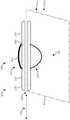
此外,如图1所示,将现有的消融导管通过心包切向地插入,使得消融导管抵靠心脏的表面平放。在这个取向中,消融导管100将能量发射到心脏组织110中,以在心脏组织110和心包120中产生损伤部130。消融心包120是不希望的,因为它可能损害位于心包的外表面上的膈神经140。此外,这种取向为医生提供了对由消融导管100施加的力的极少控制,这可能导致不稳定的心脏组织接触。Furthermore, as shown in Figure 1, the existing ablation catheter is inserted tangentially through the pericardium such that the ablation catheter lies flat against the surface of the heart. In this orientation,
希望克服本领域中的这些和/或其他缺陷。It is desirable to overcome these and/or other deficiencies in the art.
发明内容SUMMARY OF THE INVENTION
本文所描述的示例性实施例具有创新特征,其中没有单个特征是不可缺少的或仅负责其所需属性。以下描述和附图详细阐述了本公开的某些说明性实现方式,这些实现方式指示其中可以执行本公开的不同原理的若干示范性方式。然而,说明性示例并非穷举本公开的许多可能的实施例。在不限制权利要求的保护范围的情况下,现在将概述一些有利特征。在结合附图考虑时,本公开的其他目的、优点和新颖特征将在本公开的下文详细描述中阐述,这些附图旨在示出而非限制本发明。The exemplary embodiments described herein have innovative features, no single feature of which is indispensable or solely responsible for its desired attributes. The following description and drawings set forth in detail certain illustrative implementations of the disclosure, indicative of several exemplary ways in which the different principles of the disclosure may be implemented. However, the illustrative examples are not exhaustive of the many possible embodiments of the present disclosure. Without limiting the scope of protection of the claims, some advantageous features will now be outlined. Other objects, advantages and novel features of the present disclosure will be set forth in the following detailed description of the disclosure when considered in conjunction with the accompanying drawings, which are intended to illustrate and not to limit the invention.
本发明的方面涉及器械端口,该器械端口包括:细长轴,该细长轴具有近端端部和远端端部,并且沿着轴的轴线延伸,该细长轴具有流体端口,该流体端口限定在该细长轴的远端端部处的外表面中;可弯曲轴,该可弯曲轴具有近端端部,该可弯曲轴的近端端部沿着轴的轴线附接至该细长轴的远端端部,可弯曲轴被配置成仅在由轴的轴线和与轴的轴线正交的枢转轴线限定的枢转平面内弯曲;可转向末端,该可转向末端附接到该可弯曲轴的远端端部,该可转向末端包括成像系统,该成像系统包括:相机,该相机设置在该可转向末端的远端端部处;以及光发射器,该光发射器设置在可转向末端的远端端部处。该器械端口还包括偏置气囊,该偏执气囊附接到该细长轴的外表面,该偏置气囊具有与该流体端口流体连通的内部体积,该偏置气囊具有膨胀状态和收缩状态;手柄,该手柄附接到该细长轴的近端端部,该手柄包括杆,该杆与该可弯曲轴机械地连接以调节该可转向末端的可定制角度,该可定制角度在该轴的轴线与该末端的轴线之间测量;流体管,该流体管设置在该细长轴中,该流体管流体耦接到该流体端口;工作管,该工作管设置在该细长轴中,该工作管形成工作通道;消融导管,该消融导管设置在该工作通道中,该消融导管被配置成在手术部位处形成损伤部;以及基于微处理器的控制器,该控制器与该成像系统处于电连接,该控制器被配置成:从该相机获取该手术部位的图像数据;实时自动检测在手术部位形成的损伤部;以及当损伤部具有预定特点时自动停止消融导管。Aspects of the invention relate to instrument ports comprising: an elongated shaft having a proximal end and a distal end and extending along an axis of the shaft, the elongated shaft having a fluid port, the fluid A port is defined in the outer surface at the distal end of the elongated shaft; a bendable shaft having a proximal end attached to the shaft along the axis of the shaft a distal end of an elongated shaft, the bendable shaft configured to bend only within a pivot plane defined by the shaft axis and a pivot axis orthogonal to the shaft axis; a steerable tip to which the steerable tip is attached to the distal end of the steerable shaft, the steerable tip includes an imaging system including: a camera disposed at the distal end of the steerable tip; and a light emitter, the light emitter Provided at the distal end of the steerable tip. The instrument port also includes a biasing balloon attached to the outer surface of the elongated shaft, the biasing balloon having an interior volume in fluid communication with the fluid port, the biasing balloon having an expanded state and a deflated state; a handle , the handle is attached to the proximal end of the elongated shaft, the handle includes a rod mechanically connected with the bendable shaft to adjust a customizable angle of the steerable tip at a position of the shaft Measured between the axis and the axis of the tip; a fluid tube disposed in the elongated shaft, the fluid tube being fluidly coupled to the fluid port; a work tube disposed in the elongated shaft, the a working tube forming a working channel; an ablation catheter disposed in the working channel, the ablation catheter being configured to form a lesion at the surgical site; and a microprocessor-based controller in communication with the imaging system Electrically connected, the controller is configured to: acquire image data of the surgical site from the camera; automatically detect a lesion formed at the surgical site in real time; and automatically stop the ablation catheter when the lesion has a predetermined characteristic.
在一个或更多个实施例中,该预定特征包括预定尺寸。在一个或更多个实施例中,预定特性包括预定颜色。在一个或更多个实施例中,可定制角度在0°至90°的范围内,并且当可弯曲轴处于未弯曲状态时:可弯曲轴沿着轴的轴线延伸,并且可定制角度是0°。In one or more embodiments, the predetermined feature includes a predetermined size. In one or more embodiments, the predetermined characteristic includes a predetermined color. In one or more embodiments, the customizable angle is in the range of 0° to 90°, and when the bendable shaft is in the unbent state: the bendable shaft extends along the axis of the shaft, and the customizable angle is 0 °.
在一个或更多个实施例中,该偏置气囊具有膨胀状态和收缩状态,并且在该膨胀状态下,该偏置气囊具有相对于与该轴的轴线正交的垂直轴线测量的高度,该高度大于当该可定制角度是90°时从该可转向末端的远端端部到该细长轴的远端端部上的外表面测量的弯曲距离。在一个或更多个实施例中,在膨胀状态下,该偏置气囊径向不对称地膨胀。在一个或更多个实施例中,壁的第一部分与壁的第二部分相比具有相对薄的壁厚,壁的第二部分与壁的第一部分相比具有相对厚的壁厚,并且壁的第一部分在细长轴的第一侧上。In one or more embodiments, the biasing balloon has an expanded state and a deflated state, and in the expanded state the biasing balloon has a height measured relative to a vertical axis orthogonal to the axis of the shaft, the The height is greater than the bending distance measured from the distal end of the steerable tip to the outer surface on the distal end of the elongated shaft when the customizable angle is 90°. In one or more embodiments, in the expanded state, the biasing balloon expands radially asymmetrically. In one or more embodiments, the first portion of the wall has a relatively thin wall thickness compared to the second portion of the wall, the second portion of the wall has a relatively thick wall thickness compared to the first portion of the wall, and the wall The first portion of the is on the first side of the elongated shaft.
在一个或更多个实施例中,工作通道的内径大于消融导管的外径,并且流体通道限定在工作通道的内径和消融导管的外径之间。在一个或更多个实施例中,流体通道流体耦接至冲洗液源和/或真空源。在一个或更多个实施例中,消融导管包括RF消融导管。In one or more embodiments, the inner diameter of the working channel is greater than the outer diameter of the ablation catheter, and the fluid channel is defined between the inner diameter of the working channel and the outer diameter of the ablation catheter. In one or more embodiments, the fluid channel is fluidly coupled to a source of irrigation fluid and/or a source of vacuum. In one or more embodiments, the ablation catheter comprises an RF ablation catheter.
在一个或更多个实施例中,该工作管包括柔性圆筒体。在一个或更多个实施例中,柔性圆筒体包括线增强衬里。在一个或更多个实施例中,该线增强衬里包括管本体和螺旋缆线,该管本体包括氟化乙丙烯。在一个或更多个实施例中,该柔性圆筒体的内表面仅包括该管本体,以形成接纳该医疗器械的平滑表面。在一个或更多个实施例中,该轴包括具有内表面和外表面的金属管,并且狭缝的图案限定在该轴中以增加轴的柔性。In one or more embodiments, the work tube includes a flexible cylinder. In one or more embodiments, the flexible cylinder includes a wire reinforcement liner. In one or more embodiments, the wire reinforcement liner includes a pipe body including fluorinated ethylene propylene and a helical cable. In one or more embodiments, the inner surface of the flexible cylinder includes only the tube body to form a smooth surface for receiving the medical device. In one or more embodiments, the shaft includes a metal tube having an inner surface and an outer surface, and a pattern of slits is defined in the shaft to increase the flexibility of the shaft.
在一个或更多个实施例中,金属管包括不锈钢。在一个或更多个实施例中,沟槽是激光切割的。在一个或更多个实施例中,该图案包括间断的螺旋。在一个或更多个实施例中,该图案包括在金属管的第一侧和第二侧上周向延伸的多个翅片,第一侧上的翅片和第二侧上的翅片由第一间隙和第二间隙分隔开,第一间隙和第二间隙沿由轴的轴线和与轴的轴线正交的轴线限定的平面延伸。In one or more embodiments, the metal tube comprises stainless steel. In one or more embodiments, the trenches are laser cut. In one or more embodiments, the pattern includes interrupted spirals. In one or more embodiments, the pattern includes a plurality of fins extending radially on first and second sides of the metal tube, the fins on the first side and the fins on the second side being formed by The first gap and the second gap are spaced apart, the first gap and the second gap extending along a plane defined by the axis of the shaft and an axis orthogonal to the axis of the shaft.
本发明的另一方面涉及用于控制心外膜消融手术的方法,该方法包括:将包括消融工具、光学相机和光学光发射器的器械端口插入邻近目标区域的心外膜腔中;通过该光学光发射器将光学光提供到该心外膜腔中以照亮该目标区域;使用该光学相机获得该目标区域的第一图像;使该消融工具的末端朝向该目标区域转向;使用该消融工具向该目标区域施加消融能量,以在该目标区域中或该目标区域上形成损伤部;使用该光学照相机获得该目标区域的第二图像;以及在图像处理器中处理该第一图像和该第二图像中的至少一个,以确定该损伤部的特点。Another aspect of the invention relates to a method for controlling an epicardial ablation procedure, the method comprising: inserting an instrument port comprising an ablation tool, an optical camera and an optical light emitter into the epicardial cavity adjacent to the target area; an optical light emitter provides optical light into the epicardial cavity to illuminate the target area; obtains a first image of the target area using the optical camera; steers the tip of the ablation tool towards the target area; uses the ablation a tool applies ablation energy to the target area to form a lesion in or on the target area; obtains a second image of the target area using the optical camera; and processes the first image and the target area in an image processor at least one of the second images to characterize the lesion.
在一个或更多个实施例中,该方法进一步包括在获得第二图像的步骤之后获得该目标区域的第三图像,并且使用该第一图像、第二图像和第三图像中的至少两个来确定该损伤部的特点。在一个或更多个实施例中,该特点包括该损伤部的尺寸。在一个或更多个实施例中,该特点包括该损伤部的生长速率。在一个或更多个实施例中,该方法进一步包括基于确定已经在该损伤部中实现的所需结果来控制对该目标区域的消融施加。In one or more embodiments, the method further comprises obtaining a third image of the target area after the step of obtaining the second image, and using at least two of the first image, the second image and the third image to determine the characteristics of the injury. In one or more embodiments, the characteristic includes the size of the lesion. In one or more embodiments, the characteristic includes a growth rate of the lesion. In one or more embodiments, the method further includes controlling the application of ablation to the target region based on determining that the desired result has been achieved in the lesion.
在一个或更多个实施例中,实时确定该损伤部的特点。在一个或更多个实施例中,该方法进一步包括在图像处理器中处理该第一图像和第二图像中的至少一个,以自动地检测该目标区域中的解剖特征。In one or more embodiments, the lesion is characterized in real time. In one or more embodiments, the method further includes processing at least one of the first image and the second image in an image processor to automatically detect anatomical features in the target region.
本发明的另一方面涉及器械端口,该器械端口包括:细长轴,该细长轴具有近端端部和远端端部,并且沿着轴的轴线延伸,该细长轴具有流体端口,该流体端口限定在该细长轴的远端端部处的外表面中;可转向末端,该可转向末端附接到该杆的远端端部;偏置气囊,该偏置气囊附接到该细长轴的外表面,该偏置气囊具有与该流体端口流体连通的内部体积,该偏置气囊具有膨胀状态和收缩状态,其中在该膨胀状态下,该偏置气囊相对于该轴的轴线径向不对称地膨胀;以及工作管,该工作管设置在该细长轴中,该工作管形成工作通道,以接收医疗器械。Another aspect of the invention relates to an instrument port comprising: an elongated shaft having a proximal end and a distal end and extending along an axis of the shaft, the elongated shaft having a fluid port, the fluid port is defined in an outer surface at the distal end of the elongated shaft; a steerable tip attached to the distal end of the rod; a biasing balloon attached to the The outer surface of the elongated shaft, the biasing bladder having an interior volume in fluid communication with the fluid port, the biasing bladder having an expanded state and a deflated state, wherein in the expanded state the biasing bladder is relative to the shaft an axis that expands radially asymmetrically; and a working tube disposed in the elongated shaft, the working tube forming a working channel to receive a medical instrument.
在一个或更多个实施例中,器械端口进一步包括设置在细长轴中的流体管,该流体管流体耦接到流体端口。在一个或更多个实施例中,偏置气囊的近端侧附接至在流体端口的近端侧上的细长轴的外表面,并且偏置气囊的远端侧附接至在流体端口的远端侧上的细长轴的外表面。In one or more embodiments, the instrument port further includes a fluid tube disposed in the elongated shaft fluidly coupled to the fluid port. In one or more embodiments, the proximal side of the biasing balloon is attached to the outer surface of the elongated shaft on the proximal side of the fluid port, and the distal side of the biasing balloon is attached to the fluid port on the distal side The outer surface of the elongated shaft on the distal side.
在一个或更多个实施例中,该偏置气囊由具有可变壁厚的壁形成。在一个或更多个实施例中,壁的第一部分与壁的第二部分相比具有相对薄的壁厚,壁的第二部分与壁的第一部分相比具有相对厚的壁厚,并且壁的第一部分在细长轴的第一侧上,由此在膨胀状态下,偏置气囊径向地不对称地膨胀。在一个或更多个实施例中,该偏置气囊的近端侧和远端侧通过束缚件、粘合、和/或热封附接到该外表面。In one or more embodiments, the biasing balloon is formed of a wall having a variable wall thickness. In one or more embodiments, the first portion of the wall has a relatively thin wall thickness compared to the second portion of the wall, the second portion of the wall has a relatively thick wall thickness compared to the first portion of the wall, and the wall The first portion of the is on the first side of the elongated shaft, whereby in the expanded state, the biasing bladder expands radially and asymmetrically. In one or more embodiments, the proximal and distal sides of the biasing balloon are attached to the outer surface by ties, adhesives, and/or heat sealing.
在一个或更多个实施例中,该偏置气囊仅在该细长轴的第一侧上附接至该外表面,并且该偏置气囊中的偏置气囊孔流体耦接至该流体端口。在一个或更多个实施例中,该偏置气囊设置在气囊约束管部段与该细长轴的第二侧上的外表面之间,当该偏置气囊处于该膨胀状态时,该气囊约束管部段将该偏置气囊的膨胀体积约束为仅在该细长轴的第一侧。在一个或更多个实施例中,气囊约束管部段包括水平圆筒形区段。在一个或更多个实施例中,该偏置气囊相对于膨胀平面径向不对称地膨胀,该轴的轴线位于该膨胀平面中。In one or more embodiments, the biasing balloon is attached to the outer surface only on a first side of the elongated shaft, and the biasing balloon aperture in the biasing balloon is fluidly coupled to the fluid port . In one or more embodiments, the biasing balloon is disposed between the balloon-restraining tube section and the outer surface on the second side of the elongated shaft, when the biasing balloon is in the inflated state A constraining tube section constrains the inflated volume of the biasing balloon to only on the first side of the elongated shaft. In one or more embodiments, the balloon restraint tube section includes a horizontal cylindrical section. In one or more embodiments, the biasing balloon expands radially asymmetrically with respect to an expansion plane in which the axis of the shaft lies.
在一个或更多个实施例中,该偏置气囊具有部分膨胀状态,其中该偏置气囊的部分膨胀体积是在该偏置气囊的完全膨胀体积的约10%至约90%的范围内,当该偏置气囊处于该膨胀状态时,该偏置气囊具有完全膨胀体积。In one or more embodiments, the biased bladder has a partially expanded state, wherein the partially expanded volume of the biased bladder is in the range of about 10% to about 90% of the fully expanded volume of the biased bladder, When the biasing bladder is in the inflated state, the biasing bladder has a fully expanded volume.
本发明的另一方面涉及器械端口,该器械端口包括:细长轴,该细长轴具有近端端部和远端端部,并且沿着轴的轴线延伸,该细长轴具有流体端口,该流体端口限定在该细长轴的远端端部处的外表面中;可弯曲轴,该可弯曲轴附接到该细长轴的远端端部;可转向末端,该可转向末端附接到该轴的远端端部,该可转向末端沿着末端的轴线延伸;偏置气囊,该偏置气囊附接到该细长轴的外表面,该偏置气囊具有与该流体端口流体连通的内部体积,该偏置气囊具有膨胀状态和收缩状态,其中在该膨胀状态下,该偏置气囊仅在该细长轴的第一侧上膨胀;流体管,该流体管设置在该细长轴中,该流体管流体地耦接至该流体端口;以及工作管,该工作管设置在该细长轴中,该工作管形成工作通道,以接收医疗器械。Another aspect of the invention relates to an instrument port comprising: an elongated shaft having a proximal end and a distal end and extending along an axis of the shaft, the elongated shaft having a fluid port, The fluid port is defined in an outer surface at the distal end of the elongated shaft; a bendable shaft attached to the distal end of the elongated shaft; a steerable tip attached to the steerable end attached to the distal end of the shaft, the steerable tip extends along the axis of the tip; a biasing bladder attached to the outer surface of the elongated shaft, the biasing bladder having fluid communication with the fluid port a communicating internal volume, the biasing balloon having an expanded state and a deflated state, wherein in the expanded state the biasing balloon is only inflated on a first side of the elongated shaft; a fluid tube disposed on the elongated shaft In the elongated shaft, the fluid tube is fluidly coupled to the fluid port; and a working tube disposed in the elongated shaft, the working tube forming a working channel to receive a medical instrument.
在一个或更多个实施例中,器械端口进一步包括手柄,该手柄附接到该细长轴的近端端部,该手柄包括手柄流体端口,该手柄流体端口流体地耦接到流体管,以引入或接收流体。在一个或更多个实施例中,该流体管的远端端部被封盖住,以在该流体端口与该流体端口之间限定封闭流体路径。在一个或更多个实施例中,该流体管包括流体管孔,并且该流体管附接到在该细长轴的远端端部处的内表面,以将该流体管孔与该流体端口流体地耦接。In one or more embodiments, the instrument port further includes a handle attached to the proximal end of the elongated shaft, the handle including a handle fluid port fluidly coupled to the fluid tube, to introduce or receive fluids. In one or more embodiments, the distal end of the fluid tube is capped to define a closed fluid path between the fluid port and the fluid port. In one or more embodiments, the fluid tube includes a fluid tube bore, and the fluid tube is attached to an inner surface at the distal end of the elongated shaft to connect the fluid tube bore to the fluid port fluidly coupled.
在一个或更多个实施例中,该偏置气囊的近端侧附件至在流体端口的近端侧上的该细长轴的外表面上,并且该偏置气囊的远端侧附接至在流体端口的远端侧上的该细长轴的外表面上。在一个或更多个实施例中,该偏置气囊由具有可变壁厚的壁形成。在一个或更多个实施例中,壁的第一部分与壁的第二部分相比具有相对薄的壁厚,壁的第二部分与壁的第一部分相比具有相对厚的壁厚,并且壁的第一部分在细长轴的第一侧上,由此偏置气囊在膨胀状态下相对于轴的轴线径向非对称地膨胀。In one or more embodiments, the proximal side of the biasing balloon is attached to the outer surface of the elongated shaft on the proximal side of the fluid port, and the distal side of the biasing balloon is attached to On the outer surface of the elongated shaft on the distal side of the fluid port. In one or more embodiments, the biasing balloon is formed of a wall having a variable wall thickness. In one or more embodiments, the first portion of the wall has a relatively thin wall thickness compared to the second portion of the wall, the second portion of the wall has a relatively thick wall thickness compared to the first portion of the wall, and the wall The first portion of the is on the first side of the elongated shaft, whereby the biasing bladder expands radially asymmetrically with respect to the axis of the shaft in the expanded state.
在一个或更多个实施例中,该偏置气囊的近端侧和远端侧通过束缚件、粘合、和/或热封附接到该外表面。在一个或更多个实施例中,该偏置气囊的近端侧和远端侧附接至该细长轴的第一侧上的外表面,并且该偏置气囊中的偏置气囊孔流体耦接至该流体端口。In one or more embodiments, the proximal and distal sides of the biasing balloon are attached to the outer surface by ties, adhesives, and/or heat sealing. In one or more embodiments, the proximal and distal sides of the biasing balloon are attached to the outer surface on the first side of the elongated shaft, and the biasing balloon bore in the biasing balloon is fluid coupled to the fluid port.
在一个或更多个实施例中,该偏置气囊设置在气囊约束管部段与该细长轴的第二侧上的外表面之间,当该偏置气囊处于膨胀状态时,该气囊约束管部段将该偏置气囊的膨胀体积约束为仅在该细长轴的第一侧。在一个或更多个实施例中,气囊约束管部段包括水平圆筒形区段。在一个或更多个实施例中,该偏置气囊相对于膨胀平面径向不对称地膨胀,该轴的轴线位于该膨胀平面中。In one or more embodiments, the biasing balloon is disposed between the balloon-restraining tube section and the outer surface on the second side of the elongated shaft, the balloon-restraining when the biasing balloon is in the inflated state The tube section constrains the inflated volume of the biasing balloon to only the first side of the elongated shaft. In one or more embodiments, the balloon restraint tube section includes a horizontal cylindrical section. In one or more embodiments, the biasing balloon expands radially asymmetrically with respect to an expansion plane in which the axis of the shaft lies.
在一个或更多个实施例中,该偏置气囊具有部分膨胀状态,其中该偏置气囊的部分膨胀体积是在该偏置气囊的完全膨胀体积的约10%至约90%的范围内,当该偏置气囊处于膨胀状态时,该偏置气囊具有完全膨胀体积。In one or more embodiments, the biased bladder has a partially expanded state, wherein the partially expanded volume of the biased bladder is in the range of about 10% to about 90% of the fully expanded volume of the biased bladder, When the biasing bladder is in an inflated state, the biasing bladder has a fully expanded volume.
而本发明的另一方面涉及器械端口,该器械端口包括:细长轴,该细长轴具有近端端部和远端端部,并且沿着轴的轴线延伸,该细长轴具有流体端口,该流体端口限定在该细长轴的远端端部处的外表面中;可弯曲轴,该可弯曲轴附接到该细长轴的远端端部;可转向末端,该可转向末端附接到该轴的远端端部,该可转向末端沿着末端的轴线延伸;偏置气囊,该偏置气囊附接到该细长轴的外表面,该偏置气囊具有与该流体端口流体连通的内部体积,该偏置气囊具有膨胀状态和收缩状态;流体管,该流体管设置在该细长轴中,该流体管流体地耦接至该流体端口;以及工作管,该工作管设置在该细长轴中,该工作管形成工作通道,以接收医疗器械。Yet another aspect of the invention relates to an instrument port comprising: an elongated shaft having a proximal end and a distal end and extending along an axis of the shaft, the elongated shaft having a fluid port , the fluid port is defined in the outer surface at the distal end of the elongated shaft; a bendable shaft attached to the distal end of the elongated shaft; a steerable tip, the steerable tip attached to the distal end of the shaft, the steerable tip extending along the axis of the tip; a biasing bladder attached to the outer surface of the elongated shaft, the biasing bladder having a connection with the fluid port an internal volume in fluid communication, the biasing balloon having an expanded state and a deflated state; a fluid tube disposed in the elongated shaft fluidly coupled to the fluid port; and a working tube, the working tube Disposed in the elongated shaft, the working tube forms a working channel to receive a medical instrument.
在一个或更多个实施例中,器械端口进一步包括手柄,该手柄附接到细长轴的近端端部,该手柄包括手柄流体端口,该手柄流体端口流体地耦接到流体管,以引入或接收流体。在一个或更多个实施例中,该流体管的远端端部被封盖住,以在该流体端口与该流体端口之间限定封闭流体路径。在一个或更多个实施例中,流体管包括流体管孔,并且该流体管附接到在该细长轴的远端端部处的内表面,以将该流体管孔与该流体端口流体地耦接。In one or more embodiments, the instrument port further includes a handle attached to the proximal end of the elongated shaft, the handle including a handle fluid port fluidly coupled to the fluid tube to Introduce or receive fluid. In one or more embodiments, the distal end of the fluid tube is capped to define a closed fluid path between the fluid port and the fluid port. In one or more embodiments, the fluid tube includes a fluid tube bore, and the fluid tube is attached to an inner surface at the distal end of the elongated shaft to fluidize the fluid tube bore with the fluid port ground coupling.
在一个或更多个实施例中,该偏置气囊的近端侧附接至在流体端口的近端侧上的该细长轴的外表面,并且该偏置气囊的远端侧附接至在流体端口的远端侧上的该细长轴的外表面。在一个或更多个实施例中,在膨胀状态下,该偏置气囊相对于该轴的轴线径向对称地膨胀。In one or more embodiments, the proximal side of the biasing balloon is attached to the outer surface of the elongated shaft on the proximal side of the fluid port, and the distal side of the biasing balloon is attached to The outer surface of the elongated shaft on the distal side of the fluid port. In one or more embodiments, in the expanded state, the biasing bladder expands radially symmetrically with respect to the axis of the shaft.
在一个或更多个实施例中,该偏置气囊具有部分膨胀状态,其中该偏置气囊的部分膨胀体积是在该偏置气囊的完全膨胀体积的约10%至约90%的范围内,当该偏置气囊处于该膨胀状态时,该偏置气囊具有完全膨胀体积。In one or more embodiments, the biased bladder has a partially expanded state, wherein the partially expanded volume of the biased bladder is in the range of about 10% to about 90% of the fully expanded volume of the biased bladder, When the biasing bladder is in the inflated state, the biasing bladder has a fully expanded volume.
本发明的另一方面涉及器械端口,该器械端口包括:细长轴,该细长轴具有近端端部和远端端部,并且沿着轴的轴线延伸;柔性轴,该柔性轴附接到该细长轴的远端端部,该柔性轴被配置为仅在由该轴的轴线和正交于该轴的轴线的枢转轴线所限定的枢转平面内弯曲;可转向末端,该可转向末端附接到该轴的远端端部,该可转向末端沿着末端的轴线延伸;手柄,该手柄附接到该细长轴的近端端部,该手柄包括杆,该杆与该柔性轴机械连接,以调节该可转向末端的可定制角度,该可定制角度在该轴的轴线与该末端的轴线之间测量;以及工作管,该工作管设置在该细长轴和该柔性轴中,该工作管形成工作通道,以接收医疗器械。Another aspect of the invention relates to an instrument port comprising: an elongated shaft having a proximal end and a distal end and extending along an axis of the shaft; a flexible shaft to which the flexible shaft is attached To the distal end of the elongated shaft, the flexible shaft is configured to bend only in a pivot plane defined by the axis of the shaft and a pivot axis orthogonal to the axis of the shaft; the steerable end, the A steerable tip is attached to the distal end of the shaft, the steerable tip extending along the axis of the tip; a handle attached to the proximal end of the elongated shaft, the handle including a rod that is connected to the shaft The flexible shaft is mechanically connected to adjust a customizable angle of the steerable tip, the customizable angle being measured between the axis of the shaft and the axis of the tip; and a work tube disposed between the elongated shaft and the tip In the flexible shaft, the working tube forms a working channel to receive medical instruments.
在一个或更多个实施例中,在未弯曲状态下:该柔性轴沿该轴的轴线延伸,并且该柔性轴包括:沿该轴的轴线同心地设置的多个机械环,该多个机械环包括相邻机械环对,并且每个相邻机械环对通过一对机械联接装置机械地耦接,其中相应的第三轴线穿过每对机械联接装置,该相应的第三轴线正交于该轴和枢转轴线。在一个或更多个实施例中,该成对机械联接装置将柔性轴的弯曲方向机械地约束到枢转平面。In one or more embodiments, in an unbent state: the flexible shaft extends along an axis of the shaft, and the flexible shaft includes a plurality of mechanical rings disposed concentrically along the axis of the shaft, the plurality of mechanical rings The rings include pairs of adjacent mechanical rings, and each adjacent pair of mechanical rings is mechanically coupled by a pair of mechanical linkages, wherein a respective third axis passes through each pair of mechanical linkages, the respective third axis being orthogonal to The shaft and pivot axis. In one or more embodiments, the pair of mechanical linkages mechanically constrains the bending direction of the flexible shaft to the pivot plane.
在一个或更多个实施例中,该杆机械地耦接到缆线,该缆线延伸到该柔性轴的远端端部,该缆线附接到该柔性轴的内表面,该枢转轴线穿过该内表面。在一个或更多个实施例中,该杆机械地耦接到钢丝绳,该钢丝绳延伸到该柔性轴的远端端部,该钢丝绳包括该缆线。In one or more embodiments, the rod is mechanically coupled to a cable that extends to the distal end of the flexible shaft, the cable is attached to the inner surface of the flexible shaft, the pivoting The axis passes through the inner surface. In one or more embodiments, the rod is mechanically coupled to a wire rope extending to the distal end of the flexible shaft, the wire rope including the cable.
在一个或更多个实施例中,该杆机械地耦接至设置在该手柄中的转轴。在一个或更多个实施例中,该缆线附接到转轴,并且拉动杆致使转轴旋转,以朝向细长轴的近端端部拉动缆线,从而致使柔性轴在第一方向上弯曲。In one or more embodiments, the lever is mechanically coupled to a shaft provided in the handle. In one or more embodiments, the cable is attached to the shaft, and pulling the rod causes the shaft to rotate to pull the cable toward the proximal end of the elongated shaft, thereby causing the flexible shaft to bend in the first direction.
在一个或更多个实施例中,该手柄包括机械锁,该机械锁抵靠转轴施加力,以设定柔性轴的可定制角度。In one or more embodiments, the handle includes a mechanical lock that applies a force against the rotating shaft to set the customizable angle of the flexible shaft.
在一个或更多个实施例中,可定制角度在0°至90°的范围内,并且当柔性轴处于未弯曲状态时:柔性轴沿着轴的轴线延伸,并且可定制角度是0°。在一个或更多个实施例中,器械端口进一步包括附接到细长轴的远端端部的偏置气囊。In one or more embodiments, the customizable angle is in the range of 0° to 90°, and when the flexible shaft is in the unbent state: the flexible shaft extends along the axis of the shaft and the customizable angle is 0°. In one or more embodiments, the instrument port further includes a biasing balloon attached to the distal end of the elongated shaft.
在一个或更多个实施例中,该细长轴是柔性的,该细长轴具有挠曲状态和未挠曲状态,并且在该未挠曲状态下,该细长轴沿该轴的轴线延伸。在一个或更多个实施例中,当调节该可定制角度时,该细长轴保持在未挠曲状态。在一个或更多个实施例中,当调节该可定制角度时,细长轴保持在挠曲状态,当调节该可定制角度的同时,细长轴具有相同的挠曲位置。In one or more embodiments, the elongated shaft is flexible, the elongated shaft has a flexed state and an unflexed state, and in the unflexed state, the elongated shaft is along the axis of the shaft extend. In one or more embodiments, the elongated shaft remains in an unflexed state when the customizable angle is adjusted. In one or more embodiments, when the customizable angle is adjusted, the elongated shaft remains in a flexed state, and the elongated shaft has the same flexed position while the customizable angle is adjusted.
本发明的另一方面涉及器械端口,该器械端口包括:细长轴,该细长轴具有近端端部和远端端部并且沿着轴的轴线延伸;柔性轴,该柔性轴附接到该细长轴的远端端部,该柔性轴被配置为仅在由该轴的轴线和正交于该轴的轴线的枢转轴线所限定的枢转平面内弯曲;可转向末端,该可转向末端附接到该轴的远端端部,该可转向末端沿着末端的轴线延伸;手柄,该手柄附接到该细长轴的近端端部,该手柄包括:第一杆,该第一杆机械地耦接到第一缆线,该第一缆线具有附接到该柔性轴的第一侧的端部,该第一杆构造成拉动该第一缆线以使该柔性轴在该枢转平面内沿第一方向偏转;以及第二杆,该第二杆机械地耦接到第二缆线,该第二缆线具有附接到该柔性轴的第二侧的端部,该第二杆被配置成拉动该第二缆线以使该柔性轴在与该第一方向相反的第二方向偏转,该第二方向在该枢转平面内;以及工作管,该工作管设置在该细长轴和柔性轴中,该工作管形成工作通道,以接收医疗器械。Another aspect of the invention relates to an instrument port comprising: an elongated shaft having a proximal end and a distal end and extending along an axis of the shaft; a flexible shaft attached to The distal end of the elongated shaft, the flexible shaft is configured to bend only in a pivot plane defined by the axis of the shaft and a pivot axis orthogonal to the axis of the shaft; the steerable end, the steerable end A steerable tip is attached to the distal end of the shaft, the steerable tip extends along the axis of the tip; a handle is attached to the proximal end of the elongated shaft, the handle comprising: a first rod, the A first lever is mechanically coupled to a first cable having an end attached to a first side of the flexible shaft, the first lever configured to pull the first cable to cause the flexible shaft deflected in a first direction within the pivot plane; and a second lever mechanically coupled to a second cable having an end attached to a second side of the flexible shaft , the second lever is configured to pull the second cable to deflect the flexible shaft in a second direction opposite the first direction, the second direction being in the pivot plane; and a work tube, the work tube Disposed in the elongated and flexible shafts, the working tube forms a working channel to receive a medical instrument.
在一个或更多个实施例中,在未弯曲状态下:该柔性轴沿该轴的轴线延伸,并且该柔性轴包括:沿该轴的轴线同心地设置的多个机械环,该多个机械环包括相邻机械环对,并且每个相邻机械环对通过一对机械联接装置机械地耦接,其中相应的第三轴线穿过每对机械联接装置,该相应的第三轴线正交于该轴和该枢转轴线。在一个或更多个实施例中,成对机械联接装置将柔性轴的弯曲方向机械地约束到枢转平面。In one or more embodiments, in an unbent state: the flexible shaft extends along an axis of the shaft, and the flexible shaft includes a plurality of mechanical rings disposed concentrically along the axis of the shaft, the plurality of mechanical rings The rings include pairs of adjacent mechanical rings, and each adjacent pair of mechanical rings is mechanically coupled by a pair of mechanical linkages, wherein a respective third axis passes through each pair of mechanical linkages, the respective third axis being orthogonal to the shaft and the pivot axis. In one or more embodiments, the pair of mechanical linkages mechanically constrains the bending direction of the flexible shaft to the pivot plane.
在一个或更多个实施例中,柔性轴的第一侧和第二侧包括设置在柔性轴的远端端部处的内表面,并且枢转轴线穿过第一侧和第二侧的内表面。在一个或更多个实施例中,第一杆和第二杆分别机械地耦接到第一钢丝绳和第二钢丝绳,并且第一钢丝绳和第二钢丝绳分别包括第一缆线和第二缆线。In one or more embodiments, the first and second sides of the flexible shaft include inner surfaces disposed at distal ends of the flexible shaft, and the pivot axis passes through the inner surfaces of the first and second sides surface. In one or more embodiments, the first and second rods are mechanically coupled to the first and second wire ropes, respectively, and the first and second wire ropes include first and second cables, respectively .
在一个或更多个实施例中,该第一杆和第二杆机械地耦接至设置在该手柄中的转轴。在一个或更多个实施例中,第一缆线和第二缆线附接到转轴,并且,转轴被配置成当拉动第一杆时在第一方向上旋转,以将第一缆线的端部朝向细长轴的近端端部拉动,由此致使该柔性轴在该第一方向上弯曲,并且,转轴被构造成当拉动第二杆时在第二方向上旋转,以将第二缆线的端部朝向细长轴的近端端部拉动,由此致使该柔性轴在该第二方向上弯曲。在一个或更多个实施例中,转轴被配置成当转轴在第二方向上旋转时释放第一缆线上的第一力,并且转轴被配置成当转轴在第一方向上旋转时释放第二缆线上的第二力。In one or more embodiments, the first and second levers are mechanically coupled to a shaft disposed in the handle. In one or more embodiments, the first cable and the second cable are attached to the shaft, and the shaft is configured to rotate in a first direction when the first lever is pulled to rotate the first cable The end is pulled toward the proximal end of the elongated shaft, thereby causing the flexible shaft to bend in the first direction, and the shaft is configured to rotate in the second direction when the second rod is pulled to rotate the second The end of the cable is pulled toward the proximal end of the elongated shaft, thereby causing the flexible shaft to bend in the second direction. In one or more embodiments, the shaft is configured to release the first force on the first cable when the shaft rotates in the second direction, and the shaft is configured to release the first force when the shaft rotates in the first direction The second force on the second cable.
在一个或更多个实施例中,该手柄包括一个机械锁,该机械锁抵靠转轴施加力,以设定该柔性轴的可定制角度。在一个或更多个实施例中,可定制角度在-90°至90°的范围内,并且当柔性轴处于未弯曲状态时:柔性轴沿着轴的轴线延伸,并且可定制角度是0°。在一个或更多个实施例中,细长轴的挠曲位置和挠曲取向被维持的同时,可定制角度是可调节的。In one or more embodiments, the handle includes a mechanical lock that applies a force against the shaft to set the customizable angle of the flexible shaft. In one or more embodiments, the customizable angle is in the range of -90° to 90°, and when the flexible shaft is in the unbent state: the flexible shaft extends along the axis of the shaft and the customizable angle is 0° . In one or more embodiments, the customizable angle is adjustable while the flexure position and flexure orientation of the elongated shaft are maintained.
本发明的另一方面涉及器械端口,该器械端口包括:细长轴,该细长轴具有近端端部和远端端部并且沿着轴的轴线延伸,该细长轴具有流体端口,该流体端口限定在该细长轴的远端端部处的外表面中;可弯曲轴,该可弯曲轴具有近端端部,该近端端部沿着轴的轴线附件至该细长轴的远端端部,该可弯曲轴被配置成仅在由轴的轴线和与轴的轴线正交的枢转轴线所限定的枢转平面内弯曲;可转向末端,该可转向末端附接到该可弯曲轴的远端端部,该可转向末端包括:相机,该相机设置在该可转向末端的远端端部处;以及光发射器,该光发射器设置在该可转向末端的远端端部处。该器械端口进一步包括偏置气囊,该偏置气囊附接到该细长轴的外表面,该偏置气囊具有与该流体端口流体连通的内部体积,该偏置气囊具有膨胀状态和收缩状态;手柄,该手柄附接至该细长轴的近端端部,该手柄包括至少一个杆,该至少一个杆与该可弯曲轴机械连接,以调节该可转向末端的可定制角度,该可定制角度在该轴的轴线与该末端的轴线之间测量;流体管,该流体管设置在该细长轴中,该流体管流体耦接至该流体端口;以及工作管,该工作管设置在该细长轴中,该工作管形成工作通道,以接收医疗器械。Another aspect of the invention relates to an instrument port comprising: an elongated shaft having a proximal end and a distal end and extending along an axis of the shaft, the elongated shaft having a fluid port, the a fluid port is defined in an outer surface at the distal end of the elongated shaft; a bendable shaft having a proximal end attached to the shaft of the elongated shaft along the axis of the shaft a distal end, the bendable shaft configured to bend only in a pivot plane defined by an axis of the shaft and a pivot axis orthogonal to the axis of the shaft; a steerable tip attached to the the distal end of the bendable shaft, the steerable tip comprising: a camera positioned at the distal end of the steerable tip; and a light emitter positioned at the distal end of the steerable tip at the end. The instrument port further includes a biasing balloon attached to the outer surface of the elongated shaft, the biasing balloon having an interior volume in fluid communication with the fluid port, the biasing balloon having an expanded state and a deflated state; a handle attached to the proximal end of the elongated shaft, the handle including at least one rod mechanically connected to the bendable shaft to adjust a customizable angle of the steerable tip, the customizable The angle is measured between the axis of the shaft and the axis of the tip; a fluid tube disposed in the elongated shaft fluidly coupled to the fluid port; and a work tube disposed in the In the elongated shaft, the working tube forms a working channel to receive medical instruments.
在一个或更多个实施例中,可定制角度在-90°至90°的范围内,并且当可弯曲轴处于未弯曲状态时:可弯曲轴沿着轴的轴线延伸,并且可定制角度是0°。在一个或更多个实施例中,偏置气囊具有膨胀状态和收缩状态,并且在膨胀状态下,偏置气囊具有相对于正交于轴的轴线的垂直轴线测量的高度,该高度大于当可定制角度为90°时从可转向末端的远端端部到细长轴的远端端部上的外表面测量的弯曲距离。在一个或更多个实施例中,在膨胀状态下,该偏置气囊径向不对称地膨胀。在一个或更多个实施例中,壁的第一部分与壁的第二部分相比具有相对薄的壁厚,壁的第二部分与壁的第一部分相比具有相对厚的壁厚,并且壁的第一部分在细长轴的第一侧上。In one or more embodiments, the customizable angle is in the range of -90° to 90°, and when the bendable shaft is in the unbent state: the bendable shaft extends along the axis of the shaft, and the customizable angle is 0°. In one or more embodiments, the biasing balloon has an inflated state and a deflated state, and in the inflated state, the biasing balloon has a height, measured relative to a vertical axis orthogonal to the axis of the shaft, that is greater than when available Bending distance measured from the distal end of the steerable tip to the outer surface on the distal end of the elongated shaft at a custom angle of 90°. In one or more embodiments, in the expanded state, the biasing balloon expands radially asymmetrically. In one or more embodiments, the first portion of the wall has a relatively thin wall thickness compared to the second portion of the wall, the second portion of the wall has a relatively thick wall thickness compared to the first portion of the wall, and the wall The first portion of the is on the first side of the elongated shaft.
在一个或更多个实施例中,器械端口进一步包括RF消融导管,其中:工作通道的内径大于RF消融导管的外径,并且流体通道限定在工作通道的内径和RF消融导管的外径之间。在一个或更多个实施例中,流体通道流体耦接至冲洗液源和/或真空源。In one or more embodiments, the instrument port further comprises an RF ablation catheter, wherein the inner diameter of the working channel is greater than the outer diameter of the RF ablation catheter, and the fluid channel is defined between the inner diameter of the working channel and the outer diameter of the RF ablation catheter . In one or more embodiments, the fluid channel is fluidly coupled to a source of irrigation fluid and/or a source of vacuum.
在一个或更多个实施例中,该工作管包括柔性圆筒体。在一个或更多个实施例中,柔性圆筒体包括线增强衬里。在一个或更多个实施例中,该线增强衬里包括管本体和螺旋缆线,该管本体包括氟化乙丙烯。在一个或更多个实施例中,该柔性圆筒体的内表面仅包括该管本体,以形成平滑表面,以接收医疗器械。In one or more embodiments, the work tube includes a flexible cylinder. In one or more embodiments, the flexible cylinder includes a wire reinforcement liner. In one or more embodiments, the wire reinforcement liner includes a pipe body including fluorinated ethylene propylene and a helical cable. In one or more embodiments, the inner surface of the flexible cylinder includes only the tube body to form a smooth surface to receive the medical device.
在一个或更多个实施例中,该细长轴包括金属管,并且狭缝的图案限定在该轴中,以增加轴的柔性。在一个或更多个实施例中,金属管包括不锈钢。在一个或更多个实施例中,沟槽是激光切割的。在一个或更多个实施例中,该图案包括间断的螺旋。在一个或更多个实施例中,该图案包括在金属管的第一侧和第二侧上周向延伸的多个翅片,并且第一侧上的翅片和第二侧上的翅片被第一间隙和第二间隙分隔开,第一间隙和第二间隙沿由轴的轴线和与轴的轴线正交的轴线所限定的平面延伸。In one or more embodiments, the elongated shaft comprises a metal tube and a pattern of slits is defined in the shaft to increase the flexibility of the shaft. In one or more embodiments, the metal tube comprises stainless steel. In one or more embodiments, the trenches are laser cut. In one or more embodiments, the pattern includes interrupted spirals. In one or more embodiments, the pattern includes a plurality of fins extending radially on first and second sides of the metal tube, and fins on the first side and fins on the second side Separated by first and second gaps, the first and second gaps extend along a plane defined by the axis of the shaft and an axis orthogonal to the axis of the shaft.
在一个或更多个实施例中,该偏置气囊具有部分膨胀状态,其中该偏置气囊的部分膨胀体积是在该偏置气囊的完全膨胀体积的约10%至约90%的范围内,当该偏置气囊处于完全膨胀状态时,该偏置气囊具有完全膨胀体积。In one or more embodiments, the biased bladder has a partially expanded state, wherein the partially expanded volume of the biased bladder is in the range of about 10% to about 90% of the fully expanded volume of the biased bladder, When the biasing bladder is in a fully inflated state, the biasing bladder has a fully expanded volume.
附图说明Description of drawings
为了更全面地理解本概念的本质和优点,参考优选实施例的详细描述和附图。For a more complete understanding of the nature and advantages of the present concepts, reference is made to the detailed description of the preferred embodiment and the accompanying drawings.
图1是根据现有技术的使用消融导管的医疗手术的块图。Figure 1 is a block diagram of a medical procedure using an ablation catheter according to the prior art.
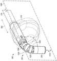
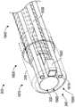
图2是根据实施例的器械端口的透视图2 is a perspective view of an instrument port according to an embodiment
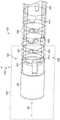
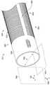
图3是根据实施例的器械端口的远端部分的透视图。3 is a perspective view of a distal portion of an instrument port according to an embodiment.
图4是根据实施例的当偏置气囊径向不对称地膨胀时,器械端口的远端部分的透视图。4 is a perspective view of a distal portion of an instrument port when the biasing balloon is inflated radially asymmetrically, according to an embodiment.
图5是根据实施例的当偏置气囊径向不对称地膨胀时,器械端口的远端部分的截面视图。5 is a cross-sectional view of the distal end portion of the instrument port when the biasing balloon is inflated radially asymmetrically, according to an embodiment.
图6是根据替代性实施例的当偏置气囊径向不对称地膨胀时,器械端口的远端部分的截面视图。6 is a cross-sectional view of the distal end portion of the instrument port when the biasing balloon is inflated radially asymmetrically, according to an alternative embodiment.
图7示出了根据实施例的在医疗手术期间当偏置气囊径向不对称地膨胀时,器械端口的侧视图。7 illustrates a side view of an instrument port when the biasing balloon is inflated radially asymmetrically during a medical procedure, according to an embodiment.
图8示出了在根据实施例的在医疗手术期间当偏置气囊径向不对称地膨胀并且可弯曲轴处于弯曲状态时,器械端口的侧视图。8 illustrates a side view of the instrument port when the biasing balloon is inflated radially asymmetrically and the bendable shaft is in a bent state during a medical procedure, according to an embodiment.
图9是根据另一实施例的当偏置气囊径向不对称地膨胀时,器械端口的远端部分的截面视图。9 is a cross-sectional view of the distal portion of the instrument port when the biasing balloon is inflated radially asymmetrically, according to another embodiment.
图10是根据实施例的当偏置气囊径向对称地膨胀时,器械端口的远端部分的透视图。10 is a perspective view of the distal end portion of the instrument port when the biasing balloon is inflated radially symmetrically, according to an embodiment.
图11示出根据实施例的当偏置气囊在医疗手术期间径向对称地膨胀时器械端口的侧视图。11 illustrates a side view of an instrument port when a biasing balloon is inflated radially symmetrically during a medical procedure, according to an embodiment.
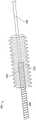
图12是不具有偏置气囊的器械端口的远端部分的透视图,以示出处于未弯曲状态的可弯曲轴的实施例。Figure 12 is a perspective view of the distal end portion of the instrument port without the biasing balloon to show an embodiment of the bendable shaft in an unbent state.
图13是具有偏置气囊的器械端口的远端部分的透视图,以示出处于弯曲状态下的可弯曲轴的实施例。13 is a perspective view of a distal portion of an instrument port with a biased balloon to illustrate an embodiment of a bendable shaft in a bent state.
图14是根据实施例的处于未弯曲状态的可弯曲轴和可转向末端的透视图。14 is a perspective view of a bendable shaft and steerable tip in an unbent state, according to an embodiment.
图15是根据实施例的缆线张力调节器的透视图。15 is a perspective view of a cable tension adjuster according to an embodiment.
图16是根据实施例的器械端口的远端部分的透视图。16 is a perspective view of a distal portion of an instrument port according to an embodiment.
图17是根据实施例的工作管的单独透视图。17 is an isolated perspective view of a work tube according to an embodiment.
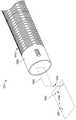
图18是根据实施例的细长轴的单独透视图。18 is an isolated perspective view of an elongated shaft according to an embodiment.
图19是根据另一实施例的细长轴的单独透视图。19 is an isolated perspective view of an elongated shaft according to another embodiment.
图20是细长轴的横截面视图。Figure 20 is a cross-sectional view of the elongated shaft.
图21是根据实施例的器械端口系统的俯视图。21 is a top view of an instrument port system according to an embodiment.
图22是根据实施例的器械端口的手柄的近端部分的透视图。22 is a perspective view of a proximal portion of a handle of an instrument port according to an embodiment.
图23是手柄的近端部分的截面视图。23 is a cross-sectional view of the proximal portion of the handle.
图24是移除了壳体的手柄的一部分的俯视图。Figure 24 is a top view of a portion of the handle with the housing removed.
图25是图24中示出的末端转向设备的单独透视图。FIG. 25 is an isolated perspective view of the tip steering apparatus shown in FIG. 24 .
图26是手柄的一部分的截面视图,以进一步示出机械锁。26 is a cross-sectional view of a portion of the handle to further illustrate the mechanical lock.
图27是可包括在控制器中的子系统的框图。27 is a block diagram of subsystems that may be included in a controller.
图28A示出了在第一时间具有第一尺寸和/或第一光学特性的损伤部。Figure 28A shows a lesion having a first dimension and/or a first optical characteristic at a first time.
图28B示出了在第二时间具有第二尺寸和/或第二光学特性的损伤部。Figure 28B shows a lesion having a second dimension and/or a second optical characteristic at a second time.
具体实施方式Detailed ways
一种器械端口包括手柄、细长轴、可弯曲轴以及可转向末端。可使用手柄上的一个或更多个杆在一个平面中可控地弯曲可弯曲轴。可弯曲轴的近端端部机械地耦接至细长轴,并且可弯曲轴的远端端部机械地耦接至可转向末端。当可弯曲轴处于未弯曲状态时,可弯曲轴沿着细长轴沿其延伸的轴的轴线延伸。当可弯曲轴处于弯曲状态时,可弯曲轴相对于轴的轴线弯曲或挠曲,以将可转向末端引导至相对于轴的轴线的可定制的角度或取向。可弯曲轴可在不影响细长轴的位置、形状、取向和/或行为的情况下弯曲。例如,在可弯曲轴220从未弯曲状态转换至弯曲状态时,细长轴可保持在挠曲状态。可替代地,在可弯曲轴220从未弯曲状态转换至弯曲状态时,细长轴可保持在未弯曲状态。An instrument port includes a handle, an elongated shaft, a bendable shaft, and a steerable tip. The bendable shaft can be controllably bent in one plane using one or more rods on the handle. The proximal end of the bendable shaft is mechanically coupled to the elongated shaft, and the distal end of the bendable shaft is mechanically coupled to the steerable tip. When the bendable shaft is in the unbent state, the bendable shaft extends along the axis of the shaft along which the elongated shaft extends. When the bendable shaft is in the bent state, the bendable shaft bends or flexes relative to the axis of the shaft to direct the steerable tip to a customizable angle or orientation relative to the axis of the shaft. The bendable shaft can be bent without affecting the position, shape, orientation and/or behavior of the elongated shaft. For example, when the
可定制的角度可以在医疗手术期间使用设置在可转向末端上的成像系统来改进解剖区域的视野。此外,可定制角度可以设置诸如消融导管的医疗器械退出可转向末端的角度,这是有利的。The customizable angle can improve the view of the anatomical region during medical procedures using an imaging system disposed on the steerable tip. In addition, the customizable angle can advantageously set the angle at which a medical instrument, such as an ablation catheter, exits the steerable tip.
偏置气囊附接至细长轴的远端端部。该偏置气囊在医疗手术期间可以从收缩状态转换到膨胀状态。在膨胀状态下,偏置气囊可以抵靠解剖特征(例如,心脏组织)设置,以在细长轴和解剖特征之间提供空间。该空间可用于将可弯曲轴从未弯曲状态转换到弯曲状态。该偏置气囊可以对称地或不对称地膨胀。此外,该偏置气囊可以部分膨胀,例如以定制细长轴与解剖特征之间的空间。A biasing balloon is attached to the distal end of the elongated shaft. The biasing balloon can transition from a deflated state to an inflated state during a medical procedure. In the inflated state, the biasing balloon can be positioned against an anatomical feature (eg, cardiac tissue) to provide a space between the elongated shaft and the anatomical feature. This space can be used to convert the bendable shaft from an unbent state to a bent state. The biased bladder can be inflated symmetrically or asymmetrically. Additionally, the biasing balloon may be partially inflated, eg, to tailor the space between the elongated shaft and the anatomical feature.
工作通道通过器械端口从器械端口的近端端部至器械端口的远端端部延伸。工作通道可以被配置成具有大于医疗器械的外半径的内半径,以在医疗器械和工作通道之间形成冲洗/真空通道。该冲洗/真空通道可以流体耦接至冲洗液体和/或真空源,该冲洗液体和/或真空源可以用于在该医疗手术之前冲洗该医疗器械的外表面,在医疗手术期间清洁该装置的面以通过相机提供清晰的图像、冲洗手术部位,和/或根据需要施加真空以移除液体和/或体液,例如血液。A working channel extends through the instrument port from the proximal end of the instrument port to the distal end of the instrument port. The working channel may be configured to have an inner radius that is greater than the outer radius of the medical device to form an irrigation/vacuum channel between the medical device and the working channel. The irrigation/vacuum channel can be fluidly coupled to an irrigation liquid and/or a vacuum source that can be used to rinse the outer surface of the medical instrument prior to the medical procedure, to clean the device's surface during the medical procedure face to provide clear images through the camera, irrigate the surgical site, and/or apply a vacuum as needed to remove fluids and/or bodily fluids, such as blood.
器械端口可以具有如在附图中所描述的多种特征。这些特征可以在多种实施例中组合和/或移除。The instrument port may have various features as described in the figures. These features may be combined and/or removed in various embodiments.
图2是根据实施例的器械端口20的透视图。器械端口20包括手柄200、细长轴210、可弯曲轴220和可转向末端230。手柄200在器械端口20的近端端部202上。可转向末端230在器械端口20的远端端部204上。FIG. 2 is a perspective view of an
可弯曲轴220可以根据手柄200上的一个或更多个杆240的位置而弯曲。可弯曲轴220可被配置成仅在一个平面中(例如,向上或向下)弯曲,而不在正交平面中(例如,从一侧到另一侧)弯曲。可转向末端230的位置和/或取向可通过致动手柄200上的杆240来控制,该杆240可通过弯曲可弯曲轴220来设定可转向末端230相对于细长轴210的可定制角度。在一些实施例中,可弯曲轴220是可选的。可弯曲轴220可在不影响细长轴210的位置、形状、取向和/或行为的情况下弯曲。The
图3是根据实施例的器械端口20的远端部分300的透视图。除了可弯曲轴220和可转向末端230之外,远端部分300还包括在图3中处于收缩状态的偏置气囊310。偏置气囊位于细长轴210的远端或远端部分215处。在医疗手术期间,可以使偏置气囊310膨胀以在解剖特征与器械端口20之间产生空间。由偏置气囊310在膨胀状态下产生的空间能够用于弯曲可弯曲轴220,以在医疗手术期间产生可转向末端230的可定制角度,例如以定制医疗器械(例如,诸如消融导管100的消融导管)穿过器械端口20的远端端部204处的工作通道320的角度。当膨胀的偏置气囊310抵靠解剖特征设置时,偏置气囊310可以在医疗手术期间为器械端口20提供稳定性。FIG. 3 is a perspective view of the
可以用流体(例如,气体和/或液体)使偏置气囊310膨胀。在一个示例中,用空气使偏置气囊310膨胀。在另一实施例中,用盐水或半盐水使偏置气囊310膨胀。该液体可以包括造影剂,该造影剂可以用于在医疗手术期间诸如用医疗成像(例如,超声、MRI、或另一医疗成像技术)观察偏置气囊310。偏置气囊310的内部体积流体耦接到流体端口340上,该流体端口340限定在细长轴的远端端部215处或远端端部215附近。流体端口340可分别用于引入流体至偏置气囊310以使偏置气囊310膨胀以及从偏置气囊310移除流体以使偏置气囊310收缩。The biasing
在膨胀状态下,偏置气囊310可被配置成相对于轴的轴线330径向对称或不对称,在可弯曲轴220处于未弯曲状态(例如,如图1至图3中所示)时,该轴的轴线330通过细长轴210、可弯曲轴220和可转向末端230的中心。当可弯曲轴220处于未弯曲状态时,轴的轴线330可以是细长轴210、可弯曲轴220和可转向末端230的对称轴线。In the inflated state, the biasing
偏置气囊310附接到细长轴210的远端端部215,以围绕流体端口340产生流体紧密密封。使用图3中的束缚件350将偏置气囊310的近端端部312和远端端部314附接在流体端口340的对应的近端侧和远端侧处。在另一实施例中,可以通过例如使用粘合剂将偏置气囊310的端部312粘结到细长轴210来附接偏置气囊310。在另一实施例中,可以通过将偏置气囊310的壁热密封到细长轴210来附接偏置气囊310。在其他实施例中,可以使用这些和/或其他附接方法。A biasing
套管250至少设置在可弯曲轴220和可转向末端230上。套管250可以提供用于在医疗手术期间插入患者体内的平滑表面,以降低组织损伤的可能性。套管250可以是柔性的,以顺应可弯曲轴220和可转向末端230,因为在医疗手术期间调节它们的相对取向和/或角度。套管250可以包括和/或可以由聚烯烃、氟聚合物、聚醚嵌段酰胺(例如,从阿科玛公司(Arkema)可获得的
图4是根据实施例的当偏置气囊310径向不对称地膨胀时,器械端口20的远端部分300的透视图。在这种实施例中,偏置气囊310在轴的轴线330的第一侧332上比在轴的轴线330的第二侧334上膨胀得更多。在一实施例中,偏置气囊310可具有可变的壁厚。在另一实施例中,可为偏置气囊310的半刚性管的一部分可以设置在轴的轴线330的第二侧334上,使得偏置气囊310在轴的轴线330的第一侧332上膨胀并且在轴的轴线的第二侧334上不膨胀。4 is a perspective view of the
在一些实施例中,偏置气囊310可以是部分膨胀的。例如,偏置气囊310可以具有是完全膨胀体积的百分比的部分膨胀体积。在特定示例中,偏置气囊310可以具有部分膨胀状态,其中偏置气囊310的部分膨胀体积是在完全膨胀体积的约10%至约90%的范围内,包括约20%、约30%、约40%、约50%、约60%、约70%、以及约80%、或任何百分比、或前述百分比中的任何两个之间的百分比。当偏置气囊310处于膨胀状态(例如,完全膨胀状态)时,偏置气囊310具有完全膨胀体积。In some embodiments, the biasing
图5是根据实施例的当偏置气囊310径向不对称地膨胀时,器械端口20的远端部分300的截面视图。截面视图是通过图4中的平面5-5截取的。这种实施例示出了偏置气囊310是由具有可变截面厚度的壁500形成的。与轴的轴线330的第二侧334上的壁500的截面厚度相比,轴的轴线330的第一侧332上的壁500具有更薄的截面厚度。同样地,与轴的轴线330的第一侧332上的壁500的截面厚度相比,轴的轴线330的第二侧334上的壁500具有更厚的截面厚度。由于在轴的轴线330的第二侧334上的壁500的相对厚的截面厚度需要较大的力来膨胀,并且在轴的轴线330的第一侧332上的壁500的相对薄的截面厚度需要较小的力来膨胀,故偏置气囊310在轴的轴线330的第一侧332上比在轴的轴线330的第二侧332上膨胀得更多。例如,当偏置气囊310膨胀时,偏置气囊310中约60%至约90%的膨胀体积可以在轴的轴线330的第一侧332上,而偏置气囊310的仅约10%至约40%的膨胀体积可以在轴的轴线330的第二侧332上。5 is a cross-sectional view of the
壁500的可变截面厚度还可以相对于膨胀平面510进行测量。当可弯曲轴220处于未弯曲状态时,膨胀平面510沿着轴的轴线330穿过细长轴210、可弯曲轴220和可转向末端230的中间。因此,轴的轴线330位于膨胀平面510中。在实施例中,可以由沿着器械端口20的长度延伸的轴的轴线330和沿着器械端口的宽度延伸的宽度轴线360(图4)描述或限定膨胀平面510。宽度轴线360与轴的轴线330正交。与在膨胀平面510上方514(例如,在其第二侧上)的壁500的截面厚度相比,在膨胀平面510下方512(例如,在其第一侧上)的偏置气囊壁500具有更薄的截面厚度。同样地,与在膨胀平面510下方512(例如,在其第一侧上)的壁500的截面厚度相比,在膨胀平面510上方514(例如,在其第二侧上)的偏置气囊壁500具有更厚的截面厚度。当偏置气囊310膨胀时,偏置气囊310中约60%至约90%的膨胀体积可在膨胀平面510的下方512(例如,在其第一侧上),而偏置气囊310的仅约10%至约40%的膨胀体积可以在膨胀平面510的上方514(例如,在其第二侧上)。The variable cross-sectional thickness of
图6是根据替代性实施例的当偏置气囊310径向不对称地膨胀时,器械端口20的远端部分300的截面视图。该截面是通过图4中的平面5-5的线截取的。在这种实施例中,偏置气囊310的壁500具有均匀的截面厚度。气囊约束管610的一部分(例如,沿着其长度切割的管,譬如沿着水平圆筒形区段切割的管)在位于偏置气囊310的一部分上方或之上附接到细长轴210。气囊约束管610是刚性的并且限制或约束偏置气囊310的膨胀,使得偏置气囊310仅在气囊约束管610未定位的地方膨胀。气囊约束管610可以设置在位于膨胀平面510的上方514(例如,在其第二侧上)的偏置气囊310的上方或之上,使得偏置气囊310仅在膨胀平面510的下方514(例如,在其第一侧上)膨胀。气囊约束管610可以包括塑料、金属和/或其他材料。偏置气囊310在轴的轴线330的第一侧332上比在轴的轴线330的第二侧334上膨胀得更多。6 is a cross-sectional view of the
图7示出了根据实施例的在医疗手术期间当偏置气囊310径向不对称地膨胀时,器械端口20的侧视图。使偏置气囊310膨胀,增加了热组织110与器械端口20(例如,细长轴210、可弯曲杆220和可转向末端230)之间的距离。一个技术优点是当偏置气囊310膨胀时,在热组织110与器械端口20之间的增加的距离提供了使可弯曲轴220朝向心脏组织110弯曲所必需的空间,例如如图8所示,以定制可转向末端230相对于细长轴210的位置和角度。例如,当可弯曲轴220处于弯曲状态时(例如,当可转向末端230与细长轴210之间的定制角度为90°时),偏置气囊310可具有大于或等于可转向末端230的远端端部204与细长轴210的远端端部的外表面812之间的弯曲距离820的半径或高度810。半径/高度810和弯曲距离820可以相对于与轴的轴线330正交的垂直轴线830进行测量。这提供了用于可弯曲顶端220弯曲以调节可转向顶端210的可定制位置和角度的足够空间。7 illustrates a side view of the
可转向末端230的可定制位置和角度可有助于使用位于可转向末端230的远端234处的成像系统800来改善心脏组织110的成像。此外,可转向末端230的可定制位置和角度可允许通过器械端口20插入的消融导管在心脏组织110中产生更深的损伤部(例如,与导管100相比),同时保护膈神经140免受任何损伤。此外,偏置气囊310可以在可转向末端230的远端端部234与心脏组织110之间提供更精确和/或更稳定的接触,这可以允许利用通过器械端口20插入的消融导管执行消融所需的接触力。消融导管可以使用包括射频(RF)、冷冻消融、针消融、激光消融和/或电穿孔的任何消融技术来操作。The customizable position and angle of
图7和图8还示出了可弯曲轴220可以在不影响细长轴210的位置、形状、取向和/或行为的情况下弯曲。例如,图7和图8示出了当可弯曲轴220弯曲时,细长轴210可沿着轴线330保持其位置。此外,当可弯曲轴220弯曲时,轴的轴线330保持相同的相对位置和角度(例如,轴的轴线330不移动)。因此,在可弯曲轴220从未弯曲状态转换至弯曲状态时,轴的轴线330可保持静止。可替代地,在可弯曲轴220从未弯曲状态转换到弯曲状态时,细长轴210可保持在挠曲状态以及相同的挠曲位置、挠曲配置和/或挠曲取向。因此,可独立于细长轴210来弯曲可弯曲轴220以及调节或设定可定制角度。FIGS. 7 and 8 also show that the
图9是根据另一替代性实施例的当偏置气囊310径向不对称地膨胀时,器械端口20的远端部分300的截面视图。该截面是通过图4中的平面5-5截取的。在这种实施例中,偏置气囊310仅附接在膨胀平面510的下方512(例如,在其第一侧上)。由于偏置气囊310没有附接在膨胀平面510的上方514(例如,第二侧上),气囊310仅在膨胀平面510的下方512膨胀。偏置气囊310仅在轴的轴线330的第一侧332上而不在轴的轴线330的第二侧334上膨胀。该替代性实施例的侧视图将看起来与图8所示的相同。9 is a cross-sectional view of the
图10是根据实施例的当偏置气囊310径向对称地膨胀时,器械端口20的远端部分300的透视图。在这种实施例中,偏置气囊310在轴的轴线330的第一侧332和第二侧334上同等地(或基本上同等地)膨胀。图11示出了根据实施例的在医疗手术期间当偏置气囊310径向对称地膨胀时,器械端口20的侧视图。径向对称的气囊提供与径向不对称气囊相同或基本相同的技术优点。然而,与径向对称气囊相比,径向不对称气囊的优点是可以使用更大的气囊,而不损害心脏的血液动力。例如,在图11中,径向对称的气囊310的上部部分1110设置抵靠心包120,这可以在心脏组织110上产生力或压力。这种力或压力是不希望的,因为它可能影响心脏中的血流。10 is a perspective view of the
如上文所讨论的,偏置气囊310可以是部分膨胀的。例如,偏置气囊310可以具有部分膨胀体积,该部分膨胀体积是完全膨胀体积的百分比。在具体示例中,偏置气囊310可以具有部分膨胀状态,其中偏置气囊310的部分膨胀体积是在完全膨胀体积的约10%至约90%的范围内,包括约20%、约30%、约40%、约50%、约60%、约70%、以及约80%、或任何百分比或前述百分比中任何两个之间的百分比。当偏置气囊310处于膨胀状态(例如,完全膨胀状态)时,偏置气囊310具有完全膨胀体积。As discussed above, the biasing
图12是不具有偏置气囊310的器械端口20的远端部分300的透视图,以示出处于未弯曲状态下的可弯曲轴220的实施例。可弯曲轴220包括沿着轴的轴线330同心设置的多个机械环1200。机械环1200可包括铰接联接装置。机械环1200的每个相邻对1210由一对机械联接装置1220机械地耦接。相应的第三轴线1230穿过每对机械联接装置1220。第三轴线1230可以与宽度轴线360相同或平行。机械联接装置1220提供了将可弯曲轴220的柔性约束在由轴的轴线330和第三轴线1230限定的刚度平面1240内的结构。刚度平面1240可以与膨胀平面510相同。12 is a perspective view of the
机械环1200沿着轴线330间隔开,以相对于与轴线330和第三轴线1330正交的枢转轴线1250提供向上或向下的柔性或可弯曲性。枢转轴线1250和轴的轴线330限定枢转平面1260,在枢转平面1260中,可弯曲轴220可向上或向下弯曲。刚度平面1240和枢转平面1260相互正交。
机械环1200和机械联接装置1220可由金属(例如,不锈钢或钛)或塑料(例如,聚酰胺、聚醚酰亚胺和/或其他塑料)形成。在实施例中,可弯曲轴220的近端端部焊接到细长轴210的远端端部。此外,可弯曲轴220的远端端部可结合到可转向末端230的近端端部。
图13是具有偏置气囊310的器械端口20的远端部分300的透视图,以示出处于弯曲状态的可弯曲轴220的实施例。在弯曲状态下,机械环1200在可弯曲轴220的远离弯曲方向的一侧上间隔开较远,并且机械环1200在可弯曲轴220的朝向弯曲方向的一侧上间隔的较近。可在可弯曲状态下调节可弯曲轴220,以形成可转向末端230相对于细长轴210的可定制角度1300。可定制角度1300可在轴的轴线330和延伸通过可转向末端230中的工作通道320的末端轴线1310之间进行测量。在未弯曲状态下,末端轴线1310和轴的轴线330共线。13 is a perspective view of the
图12和图13也示出了可弯曲轴220可在不影响细长轴210的位置、形状、取向和/或行为的情况下弯曲。例如,当可弯曲轴220弯曲时,细长轴210保持其沿着轴的轴线330的位置。此外,当可弯曲轴220弯曲时,轴的轴线330保持相同的相对位置和角度(例如,轴的轴线330不移动)。因此,在可弯曲轴220从未弯曲状态转换至弯曲状态时,轴的轴线330可保持静止。可替代地,在可弯曲轴220从未弯曲状态转换到弯曲状态时,细长轴210可保持在挠曲状态。FIGS. 12 and 13 also illustrate that the
还应注意的是,在一些实施例中,细长轴210是柔性的(例如,如例如在图18和图19中所描述的)。在未挠曲状态下,细长轴210沿着轴的轴线330延伸。在挠曲状态下,细长轴210的一些或全部不沿着轴的轴线330延伸。例如,细长轴210可以在挠曲状态下弯曲或折弯,以例如围绕解剖特征(例如,心脏)定位。在任一情况下(挠曲或未挠曲状态),在可弯曲轴220从未弯曲状态转换到弯曲状态时,可弯曲轴220可保持静止(例如,处于相同的挠曲或未挠曲配置、挠曲或未挠曲位置、挠曲或未挠曲状态、挠曲或未挠曲取向等)。因此,可独立于细长轴210来弯曲可弯曲轴220以及调节或设定可定制角度。It should also be noted that, in some embodiments, the
图14是根据实施例的处于未弯曲状态的可弯曲轴220和可转向末端230的透视图。在该视图中,机械环1200和机械联接装置1220是部分透明的,以示出可弯曲轴220中的第一缆线1401和第二缆线1402。第一缆线1401的第一端部1411附接到可弯曲轴220的远端端部的第一侧1421(例如,在内表面处)。第二缆线1402的第二端部1412附接到可弯曲轴220的远端端部的第二侧1422(例如,在内表面处)。第一端部1411和第二端部1412可压接和/或焊接到可弯曲轴220的远端端部。在未弯曲状态下,第一端部1411和第二端部1412沿着枢转轴线1250附接到可弯曲轴220的相对侧1421、1422。14 is a perspective view of the
第一缆线1401和第二缆线1402延伸至手柄200,在此处它们可以被拉动(例如,通过一个或更多个杆),以在膨胀平面1260内在对应方向上使可弯曲轴220弯曲。例如,可拉动第一缆线1401以使可弯曲轴220向上(例如,在与第一侧1421对应的第一方向上)弯曲。类似地,可拉动二缆线1402以使可弯曲轴220向下(例如,在对应于第二侧1422的第二方向上)弯曲。缆线1401、1402中的每一个均可穿过一个或更多个引导套筒1430。在实施例中,第一缆线1401和第二缆线1402可以包括第一钢丝绳和第二钢丝绳。
缆线1401、1402中的每一个均可以可选地穿过和/或附接到紧密缠绕线圈1440上,该紧密缠绕线圈1440是如图15所示的缆线张力调节器1500的一部分。紧密缠绕线圈1440的远端端部1442固定地附接(例如,焊接)至机械环1200(例如,朝向器械端口20的近端端部202的机械环1200)。缆线张力调节器1500包括紧密缠绕线圈1440和张力调节器1510。张力调节器1510附接到手柄200中的调节器板2440(图24)。张力调节器1510包括沉孔1520,沉孔1520包括啮合紧密缠绕线圈上的外螺纹的内螺纹。张力调节器1510可以在第一方向上旋转以增加缆线1402上的张力,并且在第二方向上旋转以减小缆线1402上的张力。虽然缆线张力调节器1500是相对于缆线1402示出的,但相同的缆线张力调节器1500可与缆线1401一起使用。Each of the
图16是根据实施例的器械端口20的远端部分300的透视图。在该视图中,可转向末端230是部分透明的,并且移除可弯曲轴220,以示出设置在器械端口20的远端端部204(以及远端末端230的远端端部)处的成像系统1600。成像系统1600包括围绕相机1620设置的第一光发射器和第二光发射器1610。每个光发射器1610可包括一个光纤电缆或一束光纤电缆。光纤在它们的近端端部光学地耦接到光源(例如,LED灯、白炽灯、激光器或其他光源),并且通过光纤传输光,该光在器械端口20的远端端部204处输出。在替代性实施例中,光发射器1610可以包括一个或更多个光源(例如,LED),该一个或更多个光源设置在可转向末端230中,以在器械端口20的远端端部204处输出光。在其他实施例中,可以包括附加的或更少的光发射器1610。16 is a perspective view of the
相机1620包括光传感器,该光传感器对从光发射器1610发射的一个或更多个频率的光是敏感的。相机1620电耦接到电缆1630,该电缆1630延伸到器械端口20的近端端部202,在该近端端部202处,电缆1630可以连接到控制器。控制器可包括用于光发射器1610的光源。光发射器1610发射的光可由控制器通过使用控制器上的模拟控制或显示软件中的数字控制来改变光的强度、以及通过诸如偏振和/或带通滤波等的众所周知的方法改变发射光谱,来修改。相机1620可用于获取器械端口20的远端端部204前方(例如,远端)的区域的静止或移动(例如,视频)的图像数据。例如,相机1620可以用于获取心脏组织110、心包120、以及损伤部130形成时的静止或移动的图像数据。这些图像可用于训练诸如在机器学习技术中的高级图像特征检测算法。在一些实施例中,图像数据可用于自动地检测损伤部130的特点(例如,尺寸、颜色等),以在损伤部130具有预定特点(例如,尺寸、颜色等)时,自动地停止消融。相机1620可获取2D或3D图像数据(例如,3D图像数据可包括立体静止图像和/或立体视频图像)。成像系统1600可以与成像系统800是相同的或不同的。
工作管1640设置在可弯曲轴220和可转向末端230的至少近端部分1650中。工作管1640和限定在可转向末端230的远端部分1670中的末端通道1660形成工作通道320。工作管1640可延伸到手柄200和/或器械端口20的近端端部202。工作管1640还可以延伸至可转向末端230的远端部分1670,以替换末端通道1660的部分或全部。
图17是根据实施例的工作管1640的单独透视图。工作管1640包括在结构上柔性地支撑工作管本体1710的螺旋线或螺旋形线1700。工作管本体1710可以包括聚醚嵌段酰胺(例如,
图18是根据实施例的细长轴210的单独透视图。细长轴210包括细长管1800,该细长管1800在松弛状态下沿和/或平行于轴的轴线330延伸。细长管1800可由金属(例如,不锈钢、钛和/或其他金属)、塑料和/或其他材料形成。在柔性管1800中限定多个狭缝或孔1810,以在细长管1800中产生柔性。狭缝1810可通过机加工、激光蚀刻或其他技术来形成。狭缝1810可被配置成提供相对于第一平面1820的柔性(例如,被动柔性),该第一平面1820由轴的轴线330和与轴的轴线330正交的宽度轴线1830限定。可以相对于宽度轴线1830测量细长管1800的宽度或直径。狭缝1810还可提供相对于第二平面1840的柔性(例如,被动柔性),该第二平面1840由轴的轴线330和与轴的轴线330和宽度轴线1830正交的高度轴线1850限定。可以相对于高度轴线1850测量细长管1800的高度或直径。在未挠曲状态下(如图18所示),细长管1800沿着轴的轴线330延伸。FIG. 18 is an isolated perspective view of the
缝隙1810形成可以在平面1820、1840内提供柔性的的图案,例如间断螺旋图案。在另一实施例中,如图19所示,狭缝1810布置为在细长管1800的第一侧1802和第二侧1804上沿周向延伸的多个翅片。间隙1900设置在细长管1800的第三侧1806上,第三侧1806位于细长管1800的第一侧1802上的狭缝1810与第二侧1804上的狭缝1810之间。第二间隙1900设置在细长管1800的第四侧1808上,第四侧1808位于细长管1800的第一侧1802上的狭缝1810与第二侧1804上的狭缝1810之间。第三侧1806和第四侧1808上的间隙1900相对于宽度轴线1830对准。间隙1900对应于实体细长管1800(例如,不包括狭缝1810)的区域,该实体细长管1800的区域与包括狭缝1810的细长管1800的区域相比,不是柔性的(例如,硬性的)。因此,图19中的细长管1800相对于平面1840是柔性的,但是相对于平面1820不是柔性的。The
图20是通过图3中的线20-20的细长轴210的横截面视图,以示出本文所描述的某些部件的相对布置。该横截面视图示出了第一缆线1401和第二缆线402、任选的紧密缠绕线圈1440、流体管2000、工作管1640、第一光纤电缆2011和第二光纤电缆2012、以及成像电缆2020的示例性布置。流体管2000流体耦接至流体端口340,以向偏置气囊310提供流体和/或从偏置气囊310接收流体。在示例中,流体管2000包括抵靠流体端口340设置的孔口,并且将流体管2000的远端端部盖住或密封,以迫使流体流入流体端口340至偏置气囊310或从偏置气囊310流出流体端口340(例如,以在流体端口340和偏置气囊310间限定封闭的流体路径)。第一光纤电缆2011和第二光纤电缆2012电耦接至第一光发射器1610和第二光发射器1610。在实施例中,第一光发射器和第二光发射器1610包括第一光纤电缆2011和第二光纤电缆2012。成像电缆2020电耦接至相机1620,以将图像数据从相机1620发送至外部控制器(或其他装置)、以将来自外部控制器的命令发送至相机1620(例如,调节相机的焦点)、和/或将电力提供至相机1620。在替代性实施例中,相机1620可为电池供电的、和/或可与外部控制器(或其他装置)进行无线通信。20 is a cross-sectional view of
可选的医疗装置2030(例如消融导管,譬如消融导管100)插入工作管1640内的工作通道320中。工作管1640被配置成具有大于医疗装置2030的半径2050(例如,医疗装置半径)的半径2040(例如,工作管半径)。流体通道2060在医疗装置2030的外表面2034与工作管1640的内表面1642之间形成。流体通道2060可以用于在医疗手术过程中和/或在医疗手术之前冲洗(例如,用诸如盐水或半盐水的液体)医疗装置2030的外表面2034和/或手术部位。在另外的或替代性方案中,流体通道2060可流体耦接至真空源,以施加真空至医疗装置2030的外表面2034和/或手术部位,以例如从中移除碎片和/或液体(例如,盐水或半盐水、血液等)。An optional medical device 2030 (eg, an ablation catheter, such as ablation catheter 100 ) is inserted into working
图21是根据实施例的器械端口系统2100的俯视图。器械端口系统2100包括器械端口210、流体源2110、基于微处理器的控制器2120和真空/液体冲洗源2130。在这个图中,器械端口20的细长轴210被断开,以将器械端口20适配在页面中。手柄200包括分别机械地耦接到第一缆线1401和第二缆线1402的第一杆2101和第二杆2102。朝向器械端口20的近端端部202施压第一杆2101以在第一缆线1401中产生张力,以使可弯曲轴220沿第一方向弯曲。朝向器械端口20的近端端部202施压第一杆2101还可以释放第二缆线1402中的张力。朝向器械端口20的近端端部202施压第二杆2102以在第二缆线1402中产生张力,以使可弯曲轴220沿第二方向弯曲。朝向器械端口20的近端端部202施压第二杆2102还可以释放第一缆线1401中的张力。第一杆2101和第二杆2102可与杆240相同。机械锁2105可锁定第一杆2101和第二杆2102的相对位置,这可将相应的缆线1401、缆线1402上的张力固定,由此锁定可弯曲轴220和可转向末端210的取向(例如,角度1300)。在图21中,机械锁2105定位在锁定状态下(例如,朝向远端端部204)。机械锁2105还可朝向近端端部202移动,以转换到解锁状态。21 is a top view of an
手柄流体端口2140在手柄200中(例如,在手柄200的近端端部处)形成。手柄流体端口2140流体耦接至流体源2110和流体管2000,该流体管2000流体耦接至流体端口340和偏置气囊310。流体源2110可以可释放地储存用于使偏置气囊310膨胀的预定体积的液体或气体。流体源2110可以包括注射器、罐、或可以可释放地储存流体的其他设备。流体源2110还可以从偏置气囊310接收预定体积的液体或气体,以使偏置气囊310收缩。A
光学系统端口2150也在手柄200中(例如,在手柄200的近端端部处)形成。一个或更多个电缆可以通过光学系统端口2150插入并且延伸到成像系统1600。例如,光纤电缆2011、2012和/或成像电缆2020可以通过光学系统端口2150插入。电缆的近端端部可以光学地和/或电耦接到控制器2120。控制器2120可包括光学地耦接到光纤电缆2011、2012的光源(例如,LED、激光器等)。控制器2120还可包括用于相机1620和/或与相机1620信号通信以向其发送命令并从其接收图像数据的基于微处理器的计算机的电源。控制器2120可以可选地与计算机显示器2170电子通信,计算机显示器2170可显示对应于由成像系统1600获取的图像数据的图像。
在一些实施例中,控制器2120被配置成改进和/或分析由成像系统1600获取的图像数据。除了图像本身之外,可以记录额外的有用信息,诸如每个静止或移动图像的获取时间。作为图像数据改进的示例,控制器2120可应用一个或更多个众所周知的图像分析算法以过滤噪声和/或减少眩光,该噪声和该眩光来自每个静止或移动图像序列,控制器2120可聚集静止图像或移动图像的部分以增强某些特征,将平滑、锐化、边缘检测等核心应用于静止或移动图像和/或将图像分解成经用于特征检测而优化的多种颜色或波长。In some embodiments,
控制器2120可以被配置成自动地检测(例如,实时地)可与计划的医疗手术相关的某些解剖特征。可以选择来自光发射器的照明、使用相机的获取和/或控制器2120中的处理的最佳组合,以增强对相关特征的检测。在心外膜消融手术中,控制器2120可以被配置成自动地检测(例如,实时地)心脏组织110、心包120、冠状动脉、脂肪垫和/或膈神经140。控制器2120可以使用人工智能、图像识别、机器学习推理、和/或其他方法来自动地检测解剖特征。当被启用时,可以在显示系统上将此类检测到的特征数字地标识为叠加在从相机捕获或实时获取的静止或移动影像上。另外地或可替代地,控制器2120可以被配置成在心外膜消融术期间实时地自动检测和/或追踪用任何消融技术(例如,RF、冷冻消融、针消融、激光消融和/或电穿孔)产生的损伤部。在实施例中,控制器2120可以被配置成在心外膜消融术期间实时地自动检测损伤部130的尺寸、颜色和/或其他特征或特性。控制器2120还可以与医疗装置2030(例如,消融导管)处于电连通,并且被配置成当损伤部130已经达到预定尺寸、颜色和/或特征或特性时(如通过使用人工智能、图像识别和/或其他方法)实时停止心外膜消融。The
控制器2120可包括和/或可被编程为包括如图27所示的一个或更多个子系统、控制器和/或特征。例如,控制器2120可包括和/或可被编程为包括照明子系统2701、获取子系统2702、过滤子系统2703、注释子系统2704、特征检测子系统2705、显示子系统2706、存储和检索子系统2707、损伤估计器子系统2708、瘢痕组织追踪器子系统2709、脂肪垫追踪器子系统2710、冠状血管追踪器子系统2711、消融控制子系统2712、和/或用户接口和控制子系统2713。
控制器2120可以使用照明子系统2701控制光发射器1610中的光,或控制器2120可以使用照明子系统2701生成可以通过光纤传输至光发射器1610的光(例如,光源)。此外,控制器可使用图像获取子系统2702控制相机1620并接收图像数据。所接收的图像数据可通过过滤子系统2703、注释子系统2704、特征检测子系统2705和显示子系统2706。例如,过滤子系统2703可以从图像数据过滤噪声和/或减少眩光。注释子系统2704可用于自动注释图像数据,以指示被自动检测到的任何解剖特征。注释子系统2704还可自动地将日期、时间、患者姓名或ID和/或其他信息添加到图像数据。注释子系统2704还可基于来自用户界面和控制子系统2713的用户输入来手动地添加信息。The
特征检测子系统2705可以包括人工智能、图像识别、机器学习推理、和/或用于自动地检测(例如,实时地)解剖特征和/或其他信息的其他方法。可使用注释子系统2704自动注释图像数据,以指示检测到的特征。特征检测子系统2705可基于解剖特征的尺寸、颜色、形状和/或其他特性来检测解剖特征和/或其他信息。在一些实施例中,特征检测子系统2705可用医疗手术的目标区域来编程,这可提高检测速度(例如,因此特征检测子系统2705不尝试检测不在医疗手术的目标区域附近的解剖特征)。
显示子系统2706可用于在接收到的图像数据已经穿过过滤子系统2703、注释子系统2704、和/或特征检测子系统2705之后生成图像。存储和检索子系统2707可以用于存储和/或检索图像数据,诸如将图像数据存储在可访问控制器2120的存储器(例如,可包括网络可访问的存储器的内部存储器和/或外部存储器)中和/或从可访问控制器2120的存储器检索数据。
损伤估算器子系统2708可以在医疗手术期间估算或确定损伤部130的一个或更多个特征。损伤部的特征可以包括损伤部130的尺寸、颜色、和/或其他特征或特性。损伤评估器子系统2708还可以被配置成诸如通过使用人工智能、图像识别和/或其他方法自动生成停止信号,该停止信号在损伤部130已经达到预定尺寸、颜色和/或特征或特性时,使消融导管停止心外膜消融。例如,如图28A和图28B分别示出的,损伤估计器2708可以确定损伤部2830在第一时间具有第一尺寸和/或第一光学特性,并且损伤部2830在第二时间具有第二尺寸和/或第二光学特性。在另一实施例中,损伤估计器2708可以确定尺寸、光学特性和/或其他特征的变化率,诸如分别在图28A和图28B中的第一时间与第二时间之间的变化率。Damage estimator subsystem 2708 may estimate or determine one or more characteristics of
疤痕组织追踪器子系统2709可定位和/或追踪(例如,实时地)心肌的诸如由于先前的心肌感染的现有疤痕组织。疤痕组织追踪器子系统2709的输出可被消融控制子系统2712用来诸如通过调节消融能量自动地控制消融。此外,疤痕组织追踪器子系统2709的输出可被发送到注释子系统2703,以注释所显示的图像中检测到的疤痕组织。这些注释对于操作者(例如,医师)将消融导管或其他医疗器械引导至健康组织和远离检测到的疤痕组织是有用的。此外,操作者可使用疤痕组织注释来手动地调节消融能量。疤痕组织注释可包括图形覆盖(例如,诸如红色线的彩色线)和/或透明滤色器。疤痕组织追踪器子系统2709可使用人工智能、图像识别和/或其他方法。The scar
脂肪垫追踪器子系统2710可以定位和/或追踪(例如,实时地)可能在目标部位附近的心外膜脂肪垫。消融控制子系统2712可以使用脂肪垫追踪器子系统2710的输出诸如通过调节消融能量来自动地控制消融。例如,脂肪垫是绝缘体且可能需要额外的能量来消融。此外,脂肪垫追踪器子系统2710的输出可以被发送到注释子系统2703,以对所显示的图像中所检测到的脂肪垫进行注释。这些注释对于操作者(例如,医师)可选地引导消融导管或其他医疗器械远离脂肪垫是有用的。此外,操作者可以使用脂肪垫注释来手动地调节消融能量。例如,对脂肪垫执行消融通常需要比对其他组织执行消融更多的消融能量。脂肪垫注释还可以用于提高消融效率。脂肪垫注释可以包括图形覆盖(例如,诸如红色线的彩色线)和/或透明滤色器。脂肪垫追踪器子系统2710可以使用人工智能、图像识别和/或其他方法。例如,脂肪垫追踪器子系统2710可以基于颜色(例如,黄色)和/或形状来识别脂肪垫。Fat
冠状血管追踪器子系统2711可以定位和/或追踪(例如,实时地)可能在目标部位附近的冠状血管。消融控制子系统2712可以使用冠状血管追踪器子系统2711的输出诸如通过在冠状血管附近自动停止消融来自动地控制消融。在医疗手术期间,冠状血管的消融通常是不希望的并且可能伤害患者和/或致使不希望的并发症。此外,冠状血管追踪器子系统2711的输出可被发送到注释子系统2703,以对所显示的图像中所检测到的脂肪垫进行注释。这些注释对于操作者(例如,医师)引导消融导管或其他医疗器械远离任何冠状血管以避免消融它们是有用的。冠状血管注释可包括图形覆盖(例如,诸如红色线的彩色线)和/或透明滤色器。冠状血管追踪器子系统2711可以使用人工智能、图像识别和/或其他方法。例如,冠状血管追踪器子系统2711可基于颜色(例如,蓝色或红色)和/或形状来识别冠状血管。Coronary
消融控制子系统2712可以控制消融导管的强度、频率和/或其他设置,这可以手动地或自动地控制。消融控制子系统2712可以响应于控制信号开始和停止消融。例如,消融控制子系统2712可以响应于经由用户接口和控制子系统2713的用户输入而开始或停止消融。另外地或可替代地,消融导管可以包括按钮,该按钮在被压下时生成第一信号,该第一信号致使消融控制子系统2712开始消融。当按钮被释放时,第二信号可以致使消融控制子系统2712停止消融。消融控制子系统2712还可以响应于从损伤估计器子系统2708发送的停止信号而停止消融。
返回图21,冲洗和/或真空端口2160在附接至手柄200的近端端部的适配器2180中形成。可替代地,冲洗和/或真空端口2160可在手柄200的近端端部(例如,类似于端口2140、2150)中形成。冲洗和/或真空端口2160流体耦接至流体通道2060和真空/液体冲洗源2130,以用于施加真空和/或用于将液体引入流体通道2060中。例如如图22中所示,适配器2180优选地包括Tuohy-Borst适配器,该Tuohy-Borst适配器可以包括工作端口2200,医疗装置2030(例如,消融导管)可以通过工作端口2200插入工作通道320中。阀2210可设置在冲洗和/或真空端口2160与工作端口2200之间,以根据需要将液体和/或真空引导到工作通道320中。阀2210可以由旋转适配器2180来致动。Returning to FIG. 21 , an irrigation and/or
图23是通过图22中的线23-23的手柄200的近端部分的剖面视图。该剖面不包括医疗器械2030。这个图示出了工作管1640、流体管2000、和成像线缆2300是如何耦接到手柄200中的对应端口2200、2140、2150上的示例。成像电缆2300可以包括光纤电缆2011、2012和/或成像电缆2020。FIG. 23 is a cross-sectional view of the proximal portion of
图24是根据实施例的移除了壳体的手柄200的一部分的俯视图,以示出杆2101、2102的结构和操作。杆2101、2102附接至转轴2400,第一缆线1401和第二缆线1402的第一端部2411和第二端部2412附接在转轴2400上,以形成末端转向设备2430。在该图中,朝向近端端部202按压第一杆2101,这导致转轴2400顺时针(例如,在第一方向上)旋转,以增加第一缆线1401上的张力(例如,通过减小其有效长度)。顺时针旋转转轴2400还减小第二缆线1402上的张力(例如,通过增加其有效长度)并且致使第二杆2102朝向远端端部204移动。24 is a top view of a portion of the
相反地,朝向近端端部202按压第二杆2102致使转轴2400逆时针(例如,在第二方向上)旋转,以增加第二缆线1402上的张力(例如,通过减小其有效长度)。逆时针旋转转轴2400还减小第一缆线1401上的张力(例如,通过增加其有效长度)并且导致第一杆2101朝向远端端部204移动。如可看到的,第一杆2101和第二杆2102经由转轴2400机械地耦接并且异相。例如,当在一个方向上(例如,朝向远端端部204)推动第一杆1401时,在相反方向上(例如,朝向近端端部202)推动第二杆1402,这分别致使第一缆线1401或第二缆线1402上的张力的对应的增加和第二缆线1402或第一缆线1401上的张力的对应的减小。Conversely, pressing the
这个图还示出了手柄200中的调节器板2440。调节器板2440包括与张力调节器1510上的外螺纹接合的螺纹孔口。调节器板2440附接到手柄200上和/或固定在手柄200中。张力调节器1510可以在第一方向上旋转,以朝向器械端口20的近端端部202(例如,朝向转轴2400)移动,并且在第二方向上旋转,以朝向器械端口20的远端端部204移动。由于紧密缠绕线圈1440附接到机械环1200和张力调节器1510(例如,沉孔1520中),因此沿第一方向移动张力调节器1510致使对应缆线1401、1402的张力增加。相反,沿第二方向移动张力调节器1510致使对应缆线1401、1402的张力减小。This figure also shows the
图25是图24中示出的末端转向设备2430的单独透视图。末端转向设备2430包括杆2101、2102、机械锁2105和转轴2400。缆线1401、1402在图25中未示出。机械锁2105机械地耦接到轴2500,该轴2500可滑动地耦接到锁定壳体2520中的锁定通道2510。如相对于轴的轴线2530所测量的,在锁定通道2510的锁定侧2512上的锁定壳体2520的外表面2525比在锁定通道2510的解锁侧2514上的锁定壳体2520的外表面2525相对更高。轴2500的边缘2405机械地接合锁定壳体2420的外表面2525。当轴2500滑动至锁定通道2510的锁定侧2512时,升高的外表面2525在轴2500上产生向上的力,以锁定转轴2400的旋转(例如,通过接合扩口轴制动器2540)。在图25中转轴2400是部分透明的,以进一步示出末端转向设备2430。在其他实施例中,机械锁2105可以包括按钮、杆、转盘或其他机构。FIG. 25 is an isolated perspective view of the
图26是通过图25中的线26-26的手柄200的一部分的截面图,以进一步示出机械锁2105。在图26中,机械锁2105处于解锁状态。在解锁状态下,转轴2400的一个或更多个上边缘2602与手柄200的一个或更多个内边缘2604脱离接合,以允许转轴2400自由旋转。在锁定状态下,升高的外表面2525致使轴2500向上移动(例如,沿着轴的轴线2530远离转轴2400)。轴2500机械地耦接到(例如,通过螺纹)和/或包括扩口轴制动器2540,扩口轴制动器2540随着轴2500(例如,相对于轴的轴线2530)向上和向下移动。当轴2500和扩口轴制动器2540向上移动以将机械锁2105转换至锁定状态时,扩口轴制动器2510机械地接合转轴2500,以向上推动转轴2500,这致使转轴2400的上边缘2602机械地接合手柄壳体2610的内边缘2604。上边缘2602和内边缘2604的机械接合增加了它们之间的摩擦,以机械地锁定转轴2400的旋转。锁定转轴2400的旋转设置或锁定缆线1401、1402上的张力(或缺乏张力),以设置或锁定相对于细长轴210的可弯曲轴220的弯曲和可转向末端230的可定制角度1300。FIG. 26 is a cross-sectional view of a portion of
本发明不应被认为局限于上文描述的具体实施例。在阅读本公开后,本发明可适用的各种修改、等效过程以及多种结构对于本发明所针对的领域的技术人员将是清楚的。上文所描述的实施例可以以多种方式实现。涉及过程或方法的执行的一个或更多个方面和实施例可以利用可由装置(例如,计算机、处理器或其他装置)执行的程序指令来执行或控制过程或方法的执行。The present invention should not be considered limited to the specific embodiments described above. After reading this disclosure, various modifications, equivalent processes, and various structures to which the invention may be applicable will become apparent to those skilled in the art to which the invention is directed. The embodiments described above can be implemented in various ways. One or more aspects and embodiments directed to the performance of a process or method may utilize program instructions executable by a device (eg, a computer, processor or other device) to perform or control the performance of the process or method.
在这方面,可以将各种发明概念实施为用一个或更多个程序编码的非瞬态计算机可读存储介质(或多个非瞬态计算机可读存储介质)(例如,包括瞬态或非瞬态数字存储单元、现场可编程门阵列或其他半导体器件中的电路配置的任何合适类型的计算机存储器、或其他有形计算机存储介质),当在一个或更多个计算机或其他处理器上执行时,这些程序执行实现上文所描述的各种实施例中的一个或更多个的方法。当以软件(例如,作为应用)实现时,无论是在单个计算机中提供还是在多个计算机中分布,均可以在任何合适的处理器或处理器集合上执行软件代码,。In this regard, various inventive concepts can be implemented as a non-transitory computer-readable storage medium (or non-transitory computer-readable storage media) encoded with one or more programs (eg, including a transient or non-transitory Transient digital memory cells, field programmable gate arrays, or circuit configurations in other semiconductor devices of any suitable type of computer memory, or other tangible computer storage media), when executed on one or more computers or other processors , the programs perform methods implementing one or more of the various embodiments described above. When implemented in software (eg, as an application), the software code may execute on any suitable processor or collection of processors, whether provided in a single computer or distributed among multiple computers.
进一步地,应当理解的是,作为非限制性示例,计算机可以用多种形式中的任一种来实施,诸如机架安装计算机、台式计算机、膝上计算机、或平板计算机。此外,计算机可以嵌入在通常不被视为计算机但具有合适的处理能力的装置中,包括个人数字助理(PDA)、智能电话或任何其他合适的便携式或固定电子装置。Further, it should be understood that, by way of non-limiting example, the computer may be implemented in any of a variety of forms, such as a rack mount computer, desktop computer, laptop computer, or tablet computer. Furthermore, a computer may be embedded in a device not normally considered a computer but with suitable processing capabilities, including a personal digital assistant (PDA), a smartphone or any other suitable portable or fixed electronic device.
同样,计算机可以具有一个或更多个通信装置,这些通信设备可用于将计算机互连至一个或更多个其他装置和/或系统,例如,呈任何合适形式的包括诸如企业网和智能网(IN)或互联网的局域网或广域网的一个或更多个网络。这样的网络可以基于任何合适的技术,并且可以根据任何合适的协议操作,并且可以包括无线网络或有线网络。Likewise, a computer may have one or more communication devices that can be used to interconnect the computer to one or more other devices and/or systems, for example, in any suitable form including, for example, enterprise networks and intelligent networks ( IN) or one or more networks of a local area network or a wide area network of the Internet. Such networks may be based on any suitable technology and may operate according to any suitable protocol, and may include wireless or wired networks.
同样,计算机可以具有一个或更多个输入装置和/或一个或更多个输出装置。这些装置尤其可用于呈现用户界面。可用于提供用户界面的输出装置的示例包括用于输出的视觉呈现的打印机或显示屏以及用于输出的声音呈现的扬声器或其他声音生成装置。可用于用户界面的输入装置的示例包括键盘和诸如鼠标、触摸板和数字化平板的点击装置。作为另一示例,计算机可以通过语音识别或以其他声音格式接收输入信息。Likewise, a computer may have one or more input devices and/or one or more output devices. These devices are particularly useful for presenting user interfaces. Examples of output devices that may be used to provide a user interface include a printer or display screen for visual presentation of output and a speaker or other sound generating device for sound presentation of output. Examples of input devices that can be used for a user interface include keyboards and pointing devices such as mice, touch pads, and digitizing tablets. As another example, a computer may receive input information through speech recognition or in other sound formats.
一个或更多个非瞬态计算机可读介质可以是可传送的,使得存储在其上的一个或更多个程序可以被加载到一个或更多个不同的计算机或其他处理器上,以实现上文所描述的各方面中的一个或更多个。在一些实施例中,计算机可读介质可以是非瞬态介质。One or more non-transitory computer readable media may be transportable such that one or more programs stored thereon may be loaded onto one or more different computers or other processors to implement one or more of the aspects described above. In some embodiments, the computer-readable medium may be a non-transitory medium.
本文中的术语“程序”、“应用”和“软件”在一般意义上用于指代可以用于对计算机或其他处理器进行编程以实现如上文所描述的各个方面的任何类型的计算机代码或计算机可执行指令集。此外,应当理解的是,根据一个方面,在执行时执行本申请的方法的一个或更多个计算机程序不需要留在单个计算机或处理器上,而是可以以模块化方式分布在多个不同的计算机或处理器之间,以实现本申请的各个方面。The terms "program," "application," and "software" are used herein in a generic sense to refer to any type of computer code or computer code that can be used to program a computer or other processor to implement various aspects as described above. A computer-executable instruction set. Furthermore, it should be understood that, according to one aspect, one or more computer programs that, when executed, perform the methods of the present application need not reside on a single computer or processor, but may be distributed in a modular fashion across multiple different between computers or processors to implement various aspects of this application.
计算机可执行指令可以是由一个或更多个计算机或其他装置执行的诸如程序模块的许多形式。通常,程序模块包括执行特定任务或实现特定抽象数据类型的例程、程序、对象、组件、数据结构等。可以在各种实施例中根据需要组合或分布程序模块的功能性。Computer-executable instructions may be in many forms, such as program modules, executed by one or more computers or other devices. Generally, program modules include routines, programs, objects, components, data structures, etc. that perform particular tasks or implement particular abstract data types. The functionality of the program modules may be combined or distributed as desired in various embodiments.
同样,数据结构可以任何合适的形式存储在计算机可读介质中。为了简化说明,数据结构可被示出为具有通过数据结构中的位置而相关的字段。这样的关系同样可以通过在计算机可读介质中为字段分配具有传达字段之间的关系的位置的存储来实现。然而,可以使用任何合适的机制来建立数据结构的字段中的信息之间的关系,包括通过使用指针、标签或建立数据元素之间的关系的其他机制。Also, data structures can be stored in computer-readable media in any suitable form. To simplify illustration, data structures may be shown with fields related by position in the data structure. Such relationships may also be achieved by allocating storage in a computer-readable medium for the fields with locations that convey the relationships between the fields. However, any suitable mechanism may be used to establish relationships between information in fields of a data structure, including through the use of pointers, tags, or other mechanisms that establish relationships between data elements.
因此,本公开和权利要求包括对现有方法和技术的新的和新颖的改进,新的和新颖的改进先前是未知的也没有被实施来实现上文所描述的有用结果。本方法和系统的用户将从现在由本文所描述的致使系统中的效果的特定修改及其对其用户的输出而变得可能的功能中获得有形的益处。预期的是,在实施所要求保护的本发明时,使用本文所叙述的技术部件可以实现显著改进的操作。Accordingly, the present disclosure and claims include new and novel improvements over existing methods and techniques that were not previously known or implemented to achieve the useful results described above. Users of the present method and system will derive tangible benefits from the functionality now made possible by the specific modifications described herein that cause effects in the system and its output to its users. It is contemplated that significantly improved operation can be achieved using the technical components described herein when implementing the claimed invention.
同样,如所描述的,一些方面可以体现为一种或多种方法。作为该方法的一部分所执行的动作可以按任何合适的方式排序。因此,可以构建其中动作以与所示的顺序不同的顺序执行的实施例,这可以包括同时执行一些动作,即使在说明性实施例中示出为连续动作。Also, as described, some aspects may be embodied in one or more methods. The actions performed as part of the method may be sequenced in any suitable manner. Accordingly, embodiments may be constructed in which acts are performed in an order different from that shown, which may include performing some acts concurrently, even though shown as sequential acts in an illustrative embodiment.
Claims (31)
Translated fromChineseApplications Claiming Priority (5)
| Application Number | Priority Date | Filing Date | Title |
|---|---|---|---|
| US201962936736P | 2019-11-18 | 2019-11-18 | |
| US62/936,736 | 2019-11-18 | ||
| US202063076075P | 2020-09-09 | 2020-09-09 | |
| US63/076,075 | 2020-09-09 | ||
| PCT/US2020/061093WO2021102027A1 (en) | 2019-11-18 | 2020-11-18 | Instrument port for epicardial ablation with inflatable balloon |
Publications (1)
| Publication Number | Publication Date |
|---|---|
| CN114727839Atrue CN114727839A (en) | 2022-07-08 |
Family
ID=75908205
Family Applications (4)
| Application Number | Title | Priority Date | Filing Date |
|---|---|---|---|
| CN202080080576.7APendingCN114727839A (en) | 2019-11-18 | 2020-11-18 | Device port for epicardial ablation with inflatable balloon |
| CN202080080577.1APendingCN114727813A (en) | 2019-11-18 | 2020-11-18 | System with instrument port for epicardial ablation |
| CN202080080578.6AActiveCN114727814B (en) | 2019-11-18 | 2020-11-18 | Instrument port for epicardial ablation with anatomic epicardial structures and a real-time lesion image processor |
| CN202080081244.0APendingCN114727815A (en) | 2019-11-18 | 2020-11-18 | Instrument port with flexible shaft for epicardial ablation |
Family Applications After (3)
| Application Number | Title | Priority Date | Filing Date |
|---|---|---|---|
| CN202080080577.1APendingCN114727813A (en) | 2019-11-18 | 2020-11-18 | System with instrument port for epicardial ablation |
| CN202080080578.6AActiveCN114727814B (en) | 2019-11-18 | 2020-11-18 | Instrument port for epicardial ablation with anatomic epicardial structures and a real-time lesion image processor |
| CN202080081244.0APendingCN114727815A (en) | 2019-11-18 | 2020-11-18 | Instrument port with flexible shaft for epicardial ablation |
Country Status (7)
| Country | Link |
|---|---|
| US (4) | US12279809B2 (en) |
| EP (4) | EP4061240A4 (en) |
| JP (4) | JP7631336B2 (en) |
| KR (4) | KR20220119372A (en) |
| CN (4) | CN114727839A (en) |
| AU (4) | AU2020387292A1 (en) |
| WO (4) | WO2021102027A1 (en) |
Families Citing this family (8)
| Publication number | Priority date | Publication date | Assignee | Title |
|---|---|---|---|---|
| JP2017516620A (en)* | 2014-05-23 | 2017-06-22 | アンフォラ メディカル, インコーポレイテッド | Methods and devices for treatment of pelvic conditions |
| WO2022038546A1 (en) | 2020-08-18 | 2022-02-24 | St. Jude Medical, Cardiology Division, Inc. | High-density electrode catheters with magnetic position tracking |
| CN119562785A (en)* | 2022-06-10 | 2025-03-04 | 努瓦拉公司 | Steerable catheter device with video capability and method of treatment using the device |
| CN218651946U (en)* | 2022-07-19 | 2023-03-21 | 武汉微新坦医疗科技有限公司 | Myocardial bending and cutting device and system |
| WO2024235950A1 (en)* | 2023-05-15 | 2024-11-21 | University Of Eastern Finland | Catheter delivery device for delivery of a gene therapy vector to a target region of the heart |
| WO2025038310A1 (en)* | 2023-08-14 | 2025-02-20 | Intuitive Surgical Operations, Inc. | Machine learning assisted mucosal ablation |
| CN117679034B (en)* | 2024-02-04 | 2024-05-03 | 北京智冉医疗科技有限公司 | Auxiliary implantation assembly and implantation system of flexible nerve electrode |
| CN118845197B (en)* | 2024-07-05 | 2025-03-28 | 南京市第一医院 | Ablation electrode capable of stable bending |
Citations (6)
| Publication number | Priority date | Publication date | Assignee | Title |
|---|---|---|---|---|
| US5766151A (en)* | 1991-07-16 | 1998-06-16 | Heartport, Inc. | Endovascular system for arresting the heart |
| JP2008194166A (en)* | 2007-02-09 | 2008-08-28 | Nippon Zeon Co Ltd | Balloon catheter for stone removal |
| US20100240952A1 (en)* | 2009-03-02 | 2010-09-23 | Olympus Corporation | Endoscopy method and endoscope |
| CN103200889A (en)* | 2010-10-22 | 2013-07-10 | 美敦力 | Balloon catheter with deformable fluid delivery conduit |
| CN107296638A (en)* | 2014-09-10 | 2017-10-27 | 血管解决方案公司 | Irrigate conduit and correlation technique |
| WO2018176032A1 (en)* | 2017-03-24 | 2018-09-27 | Cottone Robert J | Systems and methods for tissue displacement |
Family Cites Families (125)
| Publication number | Priority date | Publication date | Assignee | Title |
|---|---|---|---|---|
| US2243992A (en) | 1939-09-09 | 1941-06-03 | Wappler Frederick Charles | Flexible operating instrument |
| US2767705A (en) | 1954-10-08 | 1956-10-23 | Technical Oil Tool Corp | Sigmoidoscope with suction attachment for immobilizing adjacent tissue |
| US4040413A (en)* | 1974-07-18 | 1977-08-09 | Fuji Photo Optical Co. Ltd. | Endoscope |
| GB2012919B (en) | 1977-11-24 | 1982-05-19 | Wolf Gmbh Richard | Trocar sleeves |
| US4201199A (en) | 1978-01-13 | 1980-05-06 | Smith Donald C | Endoscope attachment to a viewing instrument for insertion into the uterine cavity |
| US4535773A (en) | 1982-03-26 | 1985-08-20 | Inbae Yoon | Safety puncturing instrument and method |
| JPS6023001U (en)* | 1983-07-18 | 1985-02-16 | オリンパス光学工業株式会社 | Endoscope suction control device |
| US4580551A (en)* | 1984-11-02 | 1986-04-08 | Warner-Lambert Technologies, Inc. | Flexible plastic tube for endoscopes and the like |
| JPS62186701A (en) | 1986-02-10 | 1987-08-15 | 株式会社クボタ | Rice field ridge forming device of tractor mounting system |
| JPH0346725Y2 (en)* | 1986-05-19 | 1991-10-03 | ||
| GB8822492D0 (en) | 1988-09-24 | 1988-10-26 | Considine J | Apparatus for removing tumours from hollow organs of body |
| US5195955A (en) | 1989-11-14 | 1993-03-23 | Don Michael T Anthony | Device for removal of embolic debris |
| JP2754874B2 (en) | 1990-06-13 | 1998-05-20 | 井関農機株式会社 | Abnormal treatment control method for agricultural machinery |
| JPH0447402U (en)* | 1990-08-24 | 1992-04-22 | ||
| US5122138A (en)* | 1990-11-28 | 1992-06-16 | Manwaring Kim H | Tissue vaporizing accessory and method for an endoscope |
| US5409453A (en)* | 1992-08-12 | 1995-04-25 | Vidamed, Inc. | Steerable medical probe with stylets |
| WO1993013704A1 (en)* | 1992-01-09 | 1993-07-22 | Endomedix Corporation | Bi-directional miniscope |
| US5797960A (en) | 1993-02-22 | 1998-08-25 | Stevens; John H. | Method and apparatus for thoracoscopic intracardiac procedures |
| US6346074B1 (en) | 1993-02-22 | 2002-02-12 | Heartport, Inc. | Devices for less invasive intracardiac interventions |
| US5722402A (en)* | 1994-10-11 | 1998-03-03 | Ep Technologies, Inc. | Systems and methods for guiding movable electrode elements within multiple-electrode structures |
| US5928218A (en) | 1994-12-16 | 1999-07-27 | Gelbfish; Gary A. | Medical material removal method and associated instrumentation |
| US5938587A (en)* | 1996-04-25 | 1999-08-17 | Modified Polymer Components, Inc. | Flexible inner liner for the working channel of an endoscope |
| US5842971A (en) | 1996-05-22 | 1998-12-01 | Yoon; Inbae | Optical endoscopic portals and methods of using the same to establish passages through cavity walls |
| US6689085B1 (en) | 1996-07-11 | 2004-02-10 | Eunoe, Inc. | Method and apparatus for treating adult-onset dementia of the Alzheimer's type |
| US6293282B1 (en) | 1996-11-05 | 2001-09-25 | Jerome Lemelson | System and method for treating select tissue in living being |
| US5899915A (en) | 1996-12-02 | 1999-05-04 | Angiotrax, Inc. | Apparatus and method for intraoperatively performing surgery |
| US5848966A (en) | 1997-03-04 | 1998-12-15 | Graphic Controls Corporation | Medical device easily removed from skin and a method of removal therefrom |
| US6086583A (en)* | 1997-06-05 | 2000-07-11 | Asahi Kogaku Kogyo Kabushiki Kaisha | Electric cautery for endoscope |
| JPH1199156A (en) | 1997-07-29 | 1999-04-13 | Olympus Optical Co Ltd | Access device for surgical treatment |
| US5924976A (en) | 1997-08-21 | 1999-07-20 | Stelzer; Paul | Minimally invasive surgery device |
| US6238389B1 (en)* | 1997-09-30 | 2001-05-29 | Boston Scientific Corporation | Deflectable interstitial ablation device |
| US5984946A (en)* | 1998-02-27 | 1999-11-16 | Gupta; Mukesh | Diagnostic and guiding catheter |
| DE19815598B4 (en) | 1998-04-07 | 2007-01-18 | Stm Medizintechnik Starnberg Gmbh | Flexible access tube with everting tube system |
| US6129713A (en) | 1998-08-11 | 2000-10-10 | Embol-X, Inc. | Slidable cannula and method of use |
| US6178346B1 (en) | 1998-10-23 | 2001-01-23 | David C. Amundson | Infrared endoscopic imaging in a liquid with suspended particles: method and apparatus |
| US20040044350A1 (en)* | 1999-04-09 | 2004-03-04 | Evalve, Inc. | Steerable access sheath and methods of use |
| EP1060758A1 (en) | 1999-06-15 | 2000-12-20 | Medtronic, Inc. | Aortic occlusion cannula |
| US6780151B2 (en)* | 1999-10-26 | 2004-08-24 | Acmi Corporation | Flexible ureteropyeloscope |
| US6749560B1 (en)* | 1999-10-26 | 2004-06-15 | Circon Corporation | Endoscope shaft with slotted tube |
| US6641562B1 (en) | 2000-05-10 | 2003-11-04 | Hps Medical, Inc. | Apparatus and method of intravenous fluid infusion |
| US6840246B2 (en) | 2000-06-20 | 2005-01-11 | University Of Maryland, Baltimore | Apparatuses and methods for performing minimally invasive diagnostic and surgical procedures inside of a beating heart |
| WO2002004064A1 (en) | 2000-07-12 | 2002-01-17 | Oma Medical Technologies, Inc. | Minimally invasive bypass system and related methods |
| US6520939B2 (en) | 2001-02-13 | 2003-02-18 | Scimed Life Systems, Inc. | Hemostasis valve |
| JP4633282B2 (en)* | 2001-03-12 | 2011-02-16 | オリンパス株式会社 | Endoscope |
| WO2002094363A2 (en)* | 2001-05-21 | 2002-11-28 | Medtronic,Inc. | Trans-septal catheter with retention mechanism |
| US20080275439A1 (en)* | 2002-01-25 | 2008-11-06 | David Francischelli | Cardiac ablation and electrical interface system and instrument |
| US7025759B2 (en)* | 2002-02-04 | 2006-04-11 | Ebi, L.P. | Steerable catheter |
| EP1513440A2 (en) | 2002-05-30 | 2005-03-16 | The Board of Trustees of The Leland Stanford Junior University | Apparatus and method for coronary sinus access |
| US8287555B2 (en) | 2003-02-06 | 2012-10-16 | Guided Delivery Systems, Inc. | Devices and methods for heart valve repair |
| US7226410B2 (en) | 2002-12-05 | 2007-06-05 | Ethicon-Endo Surgery, Inc. | Locally-propelled, intraluminal device with cable loop track and method of use |
| US20040199052A1 (en)* | 2003-04-01 | 2004-10-07 | Scimed Life Systems, Inc. | Endoscopic imaging system |
| EP1687056B9 (en) | 2003-11-20 | 2013-09-11 | Children's Medical Center Corporation | Trocar for use during endoscopy |
| US7500947B2 (en) | 2004-01-29 | 2009-03-10 | Cannonflow, Inc. | Atraumatic arthroscopic instrument sheath |
| US8512229B2 (en) | 2004-04-14 | 2013-08-20 | Usgi Medical Inc. | Method and apparatus for obtaining endoluminal access |
| US7691137B2 (en)* | 2004-09-28 | 2010-04-06 | Boston Scientific Scimed, Inc. | Rotatable sheath, assembly and method of manufacture of same |
| US9005115B2 (en) | 2005-04-04 | 2015-04-14 | Invuity, Inc. | Illuminated telescoping cannula |
| JP4675149B2 (en)* | 2005-05-13 | 2011-04-20 | 独立行政法人理化学研究所 | Spectroscopic probe for blood vessel diagnosis |
| WO2006123397A1 (en) | 2005-05-16 | 2006-11-23 | Olympus Medical Systems Corp. | Endoscope system, control program for endoscope system, and control method for endoscope system |
| US7819868B2 (en)* | 2005-06-21 | 2010-10-26 | St. Jude Medical, Atrial Fibrilation Division, Inc. | Ablation catheter with fluid distribution structures |
| US8190238B2 (en) | 2005-12-09 | 2012-05-29 | Hansen Medical, Inc. | Robotic catheter system and methods |
| US8292827B2 (en)* | 2005-12-12 | 2012-10-23 | Boston Scientific Scimed, Inc. | Micromachined medical devices |
| US9833595B2 (en)* | 2005-12-30 | 2017-12-05 | Biosense Webster, Inc. | Dual-lever bi-directional handle |
| US8394015B2 (en) | 2006-01-05 | 2013-03-12 | Children's Medical Center Corporation | Instrument port for minimally invasive cardiac surgery |
| WO2007100846A2 (en)* | 2006-02-28 | 2007-09-07 | Emphasys Medical, Inc. | Endoscopic tool |
| JP5116985B2 (en)* | 2006-04-13 | 2013-01-09 | 富士フイルム株式会社 | Endoscope |
| US9314263B2 (en)* | 2006-06-30 | 2016-04-19 | Atheromed, Inc. | Atherectomy devices, systems, and methods |
| WO2008095052A2 (en)* | 2007-01-30 | 2008-08-07 | Loma Vista Medical, Inc., | Biological navigation device |
| WO2010005426A1 (en)* | 2008-07-07 | 2010-01-14 | Tanscardiac Therapeutics, Llc | Epicardium payload delivery device and method |
| US11564556B2 (en)* | 2008-11-07 | 2023-01-31 | Izomed, Inc. | Endoscope accessory |
| US9468364B2 (en)* | 2008-11-14 | 2016-10-18 | Intuitive Surgical Operations, Inc. | Intravascular catheter with hood and image processing systems |
| US8702773B2 (en)* | 2008-12-17 | 2014-04-22 | The Spectranetics Corporation | Eccentric balloon laser catheter |
| US8123721B2 (en)* | 2008-12-31 | 2012-02-28 | St. Jude Medical, Atrial Fibrillation Division, Inc. | Catheter having independently-deflectable segments and method of its manufacture |
| JP5254125B2 (en)* | 2009-05-11 | 2013-08-07 | 富士フイルム株式会社 | Internal pressure detecting device and endoscope device for expansion / contraction member |
| US8864656B2 (en)* | 2009-06-03 | 2014-10-21 | Gyrus Acmi, Inc. | Endoscope combined deflection control and lock |
| US8920369B2 (en)* | 2009-06-24 | 2014-12-30 | Shifamed Holdings, Llc | Steerable delivery sheaths |
| ES2874194T3 (en)* | 2009-12-16 | 2021-11-04 | Boston Scient Scimed Inc | Arrangements for making an endoluminal anatomical structure |
| EP4183441A1 (en)* | 2010-02-26 | 2023-05-24 | The Board of Trustees of the Leland Stanford Junior University | Systems for endoluminal valve creation |
| CN105193371B (en)* | 2010-03-09 | 2020-11-24 | 智能医疗系统有限公司 | Balloon endoscope and methods of making and using the same |
| JP5285649B2 (en)* | 2010-03-31 | 2013-09-11 | 富士フイルム株式会社 | Endoscope hood |
| EP2563255B1 (en) | 2010-04-26 | 2017-03-22 | Medtronic Ardian Luxembourg S.à.r.l. | Catheter apparatuses and systems for renal neuromodulation |
| US9055960B2 (en)* | 2010-11-15 | 2015-06-16 | Intuitive Surgical Operations, Inc. | Flexible surgical devices |
| US10070793B2 (en)* | 2010-11-27 | 2018-09-11 | Securus Medical Group, Inc. | Ablation and temperature measurement devices |
| US20120178994A1 (en)* | 2011-01-11 | 2012-07-12 | Drew Schembre | Apparatus and method for assisting in the delivery of medical instruments into body organs |
| JP2012192028A (en)* | 2011-03-16 | 2012-10-11 | Fujifilm Corp | Overtube |
| US10278774B2 (en)* | 2011-03-18 | 2019-05-07 | Covidien Lp | Selectively expandable operative element support structure and methods of use |
| JP5323268B2 (en)* | 2011-04-13 | 2013-10-23 | オリンパスメディカルシステムズ株式会社 | Endoscope |
| US8545409B2 (en)* | 2011-04-14 | 2013-10-01 | St. Jude Medical, Inc. | Arrangement and interface for RF ablation system with acoustic feedback |
| HK1198738A1 (en) | 2011-05-03 | 2015-06-05 | Endosee股份有限公司 | Method and apparatus for hysteroscopy and endometrial biopsy |
| US9730726B2 (en)* | 2011-10-07 | 2017-08-15 | W. L. Gore & Associates, Inc. | Balloon assemblies having controllably variable topographies |
| CN103370000B (en)* | 2011-11-25 | 2015-12-09 | 奥林巴斯株式会社 | Endoscope |
| WO2013082310A1 (en)* | 2011-12-02 | 2013-06-06 | Barosense, Inc. | Positioning device and articulation assembly for remote positioning of a tool |
| EP2797490B1 (en)* | 2011-12-29 | 2016-11-09 | Cook Medical Technologies LLC | Space-optimized visualization catheter having a camera train holder in a catheter with off-centered lumens |
| WO2013163322A1 (en)* | 2012-04-24 | 2013-10-31 | Cibiem, Inc. | Endovascular catheters and methods for carotid body ablation |
| US10004877B2 (en)* | 2012-05-07 | 2018-06-26 | St. Jude Medical, Atrial Fibrillation Division, Inc. | Deflectable catheter shaft section, catheter incorporating same, and method of manufacturing same |
| US8998844B2 (en)* | 2012-06-04 | 2015-04-07 | St. Jude Medical, Atrial Fibrillation Division, Inc. | Handle extension for an elongate medical device |
| US9993295B2 (en) | 2012-08-07 | 2018-06-12 | Covidien Lp | Microwave ablation catheter and method of utilizing the same |
| JP6185294B2 (en)* | 2013-06-11 | 2017-08-23 | オリンパス株式会社 | Endoscope |
| EP3057511B1 (en)* | 2013-10-14 | 2022-12-28 | Adagio Medical, Inc. | Endoesophageal balloon catheter and system |
| JP6737705B2 (en)* | 2013-11-14 | 2020-08-12 | ザ・ジョージ・ワシントン・ユニバーシティThe George Washingtonuniversity | Method of operating system for determining depth of injury site and system for generating images of heart tissue |
| EP3077035B1 (en) | 2013-12-06 | 2022-11-02 | Kalila Medical, Inc. | Steerable medical devices |
| US10342606B2 (en)* | 2014-05-06 | 2019-07-09 | Cosman Instruments, Llc | Electrosurgical generator |
| CA2966131A1 (en)* | 2014-06-05 | 2015-12-10 | Medrobotics Corporation | Articulating robotic probes, systems and methods incorporating the same, and methods for performing surgical procedures |
| HK1244652A1 (en)* | 2014-10-20 | 2018-08-17 | Research Development International Corporation | Steerable micro-endoscope |
| KR102499045B1 (en) | 2014-11-03 | 2023-02-10 | 더 조지 워싱턴 유니버시티 | Systems and methods for lesion assessment |
| CN107835704B (en) | 2015-03-27 | 2020-12-15 | 项目莫里股份有限公司 | Fluid drive system for catheter articulation and other uses |
| EP3278714A1 (en)* | 2015-05-07 | 2018-02-07 | Olympus Corporation | Endoscope system |
| US10779904B2 (en) | 2015-07-19 | 2020-09-22 | 460Medical, Inc. | Systems and methods for lesion formation and assessment |
| US12082775B2 (en)* | 2015-12-18 | 2024-09-10 | Boston Scientific Scimed, Inc. | Radially-directed balloon visualization device |
| US20170203076A1 (en)* | 2016-01-15 | 2017-07-20 | Boston Scientific Scimed, Inc. | Slotted tube with planar steering |
| EP3413822B1 (en) | 2016-02-11 | 2023-08-30 | Arrinex, Inc. | Device for image guided post-nasal nerve ablation |
| WO2017192897A1 (en)* | 2016-05-06 | 2017-11-09 | Cardioscout Solutions, Inc. | Access devices and methods for treatment of medical conditions and delivery of injectables |
| JP6780328B2 (en)* | 2016-07-06 | 2020-11-04 | 日本ゼオン株式会社 | Balloon catheter for stone removal |
| US10610345B2 (en)* | 2016-09-21 | 2020-04-07 | Ethicon, Inc. | Applicator instruments for dispensing surgical fasteners having articulating shafts |
| CN110087526B (en)* | 2016-12-30 | 2022-01-14 | 波士顿科学国际有限公司 | System for minimally invasive treatment inside body cavity |
| US10537710B2 (en)* | 2017-04-20 | 2020-01-21 | Covidien Lp | Catheter including an inner liner with a flexible distal section |
| WO2018226751A1 (en)* | 2017-06-05 | 2018-12-13 | St. Jude Medical, Cardiology Division, Inc. | Balloon-in-basket ablation catheter |
| WO2019002186A1 (en)* | 2017-06-26 | 2019-01-03 | Ambu A/S | A bending section for an endoscope |
| US10881838B2 (en)* | 2017-07-19 | 2021-01-05 | Hoya Corporation | Endoscopic balloon catheter |
| WO2019087254A1 (en) | 2017-10-30 | 2019-05-09 | オリンパス株式会社 | Endoscope system |
| US11723738B2 (en) | 2017-11-06 | 2023-08-15 | University Of Tennessee Research Foundation | Surgical device tip with deflectable joint |
| WO2019094413A1 (en) | 2017-11-07 | 2019-05-16 | Children's Medical Center Corporation | Interventional device with adjustable configuration |
| EP3517017B1 (en)* | 2018-01-26 | 2023-01-18 | Ambu A/S | A method for fixation of a wire portion of an endoscope, and an endoscope |
| US10894148B2 (en)* | 2018-01-31 | 2021-01-19 | C. R. Bard, Inc. | Balloon-manipulating devices, balloon catheter assemblies, and methods thereof |
| US10610282B2 (en) | 2018-05-09 | 2020-04-07 | John H. Shadduck | Medical ablation devices and methods |
| EP3941374A1 (en)* | 2019-03-22 | 2022-01-26 | Boston Scientific Scimed Inc. | Automated electrode recommendation for ablation systems |
- 2020
- 2020-11-18CNCN202080080576.7Apatent/CN114727839A/enactivePending
- 2020-11-18WOPCT/US2020/061093patent/WO2021102027A1/ennot_activeCeased
- 2020-11-18CNCN202080080577.1Apatent/CN114727813A/enactivePending
- 2020-11-18WOPCT/US2020/061070patent/WO2021102009A1/ennot_activeCeased
- 2020-11-18EPEP20888879.2Apatent/EP4061240A4/enactivePending
- 2020-11-18AUAU2020387292Apatent/AU2020387292A1/enactivePending
- 2020-11-18WOPCT/US2020/061078patent/WO2021102014A1/ennot_activeCeased
- 2020-11-18KRKR1020227019532Apatent/KR20220119372A/ennot_activeWithdrawn
- 2020-11-18AUAU2020386532Apatent/AU2020386532A1/enactivePending
- 2020-11-18JPJP2022528981Apatent/JP7631336B2/enactiveActive
- 2020-11-18EPEP20889018.6Apatent/EP4061241A4/enactivePending
- 2020-11-18JPJP2022528983Apatent/JP2023503035A/enactivePending
- 2020-11-18AUAU2020386525Apatent/AU2020386525A1/enactivePending
- 2020-11-18AUAU2020388050Apatent/AU2020388050A1/enactivePending
- 2020-11-18KRKR1020227019590Apatent/KR20220121234A/ennot_activeWithdrawn
- 2020-11-18EPEP20889664.7Apatent/EP4061242A4/ennot_activeWithdrawn
- 2020-11-18WOPCT/US2020/061100patent/WO2021102033A1/ennot_activeCeased
- 2020-11-18USUS16/951,773patent/US12279809B2/enactiveActive
- 2020-11-18JPJP2022528982Apatent/JP2023501756A/enactivePending
- 2020-11-18KRKR1020227019588Apatent/KR20220119373A/enactivePending
- 2020-11-18CNCN202080080578.6Apatent/CN114727814B/enactiveActive
- 2020-11-18USUS16/951,874patent/US20210145510A1/enactivePending
- 2020-11-18EPEP20890510.9Apatent/EP4061243A4/enactivePending
- 2020-11-18JPJP2022528954Apatent/JP2023502121A/enactivePending
- 2020-11-18USUS16/951,828patent/US20210145509A1/enactivePending
- 2020-11-18USUS16/951,903patent/US20210145511A1/enactivePending
- 2020-11-18CNCN202080081244.0Apatent/CN114727815A/enactivePending
- 2020-11-18KRKR1020227019507Apatent/KR20220100911A/enactivePending
Patent Citations (6)
| Publication number | Priority date | Publication date | Assignee | Title |
|---|---|---|---|---|
| US5766151A (en)* | 1991-07-16 | 1998-06-16 | Heartport, Inc. | Endovascular system for arresting the heart |
| JP2008194166A (en)* | 2007-02-09 | 2008-08-28 | Nippon Zeon Co Ltd | Balloon catheter for stone removal |
| US20100240952A1 (en)* | 2009-03-02 | 2010-09-23 | Olympus Corporation | Endoscopy method and endoscope |
| CN103200889A (en)* | 2010-10-22 | 2013-07-10 | 美敦力 | Balloon catheter with deformable fluid delivery conduit |
| CN107296638A (en)* | 2014-09-10 | 2017-10-27 | 血管解决方案公司 | Irrigate conduit and correlation technique |
| WO2018176032A1 (en)* | 2017-03-24 | 2018-09-27 | Cottone Robert J | Systems and methods for tissue displacement |
Also Published As
| Publication number | Publication date |
|---|---|
| EP4061242A1 (en) | 2022-09-28 |
| KR20220100911A (en) | 2022-07-18 |
| JP2023502121A (en) | 2023-01-20 |
| EP4061241A1 (en) | 2022-09-28 |
| JP2023503035A (en) | 2023-01-26 |
| WO2021102014A1 (en) | 2021-05-27 |
| AU2020386532A1 (en) | 2022-05-26 |
| JP2023501755A (en) | 2023-01-18 |
| EP4061240A4 (en) | 2024-01-24 |
| EP4061240A1 (en) | 2022-09-28 |
| AU2020388050A1 (en) | 2022-05-26 |
| WO2021102027A1 (en) | 2021-05-27 |
| EP4061243A4 (en) | 2024-01-17 |
| EP4061243A1 (en) | 2022-09-28 |
| US20210145511A1 (en) | 2021-05-20 |
| CN114727813A (en) | 2022-07-08 |
| WO2021102009A1 (en) | 2021-05-27 |
| US20210145510A1 (en) | 2021-05-20 |
| KR20220119372A (en) | 2022-08-29 |
| EP4061242A4 (en) | 2024-01-17 |
| KR20220119373A (en) | 2022-08-29 |
| JP2023501756A (en) | 2023-01-18 |
| CN114727814A (en) | 2022-07-08 |
| AU2020386525A1 (en) | 2022-05-26 |
| US20210145509A1 (en) | 2021-05-20 |
| CN114727815A (en) | 2022-07-08 |
| CN114727814B (en) | 2025-01-17 |
| AU2020387292A1 (en) | 2022-05-26 |
| US12279809B2 (en) | 2025-04-22 |
| EP4061241A4 (en) | 2023-11-22 |
| WO2021102033A1 (en) | 2021-05-27 |
| US20210145262A1 (en) | 2021-05-20 |
| KR20220121234A (en) | 2022-08-31 |
| JP7631336B2 (en) | 2025-02-18 |
Similar Documents
| Publication | Publication Date | Title |
|---|---|---|
| CN114727814B (en) | Instrument port for epicardial ablation with anatomic epicardial structures and a real-time lesion image processor | |
| US12390095B2 (en) | Imaging apparatus and systems and methods for using them | |
| US20220218390A1 (en) | Access devices and methods for treatment of medical conditions and delivery of injectables | |
| US20200046393A1 (en) | Apparatus and methods for performing minimally-invasive surgical procedures | |
| US20240156462A1 (en) | Devices and methods for left atrial appendage closure | |
| US8235985B2 (en) | Visualization and ablation system variations | |
| US20090143640A1 (en) | Combination imaging and treatment assemblies | |
| US20090062790A1 (en) | Direct visualization bipolar ablation systems | |
| US20130267875A1 (en) | Methods and systems for ablating tissue | |
| US20080183036A1 (en) | Systems and methods for unobstructed visualization and ablation | |
| US20240033470A1 (en) | Controllable Expandable Catheter | |
| JP2016523584A (en) | Reverse loop ablation device |
Legal Events
| Date | Code | Title | Description |
|---|---|---|---|
| PB01 | Publication | ||
| PB01 | Publication | ||
| SE01 | Entry into force of request for substantive examination | ||
| SE01 | Entry into force of request for substantive examination |