CN114723897B - Planning method and device for intelligent tibial osteotomy navigation system - Google Patents
Planning method and device for intelligent tibial osteotomy navigation systemDownload PDFInfo
- Publication number
- CN114723897B CN114723897BCN202210642831.3ACN202210642831ACN114723897BCN 114723897 BCN114723897 BCN 114723897BCN 202210642831 ACN202210642831 ACN 202210642831ACN 114723897 BCN114723897 BCN 114723897B
- Authority
- CN
- China
- Prior art keywords
- tibia
- osteotomy
- plane
- point
- key point
- Prior art date
- Legal status (The legal status is an assumption and is not a legal conclusion. Google has not performed a legal analysis and makes no representation as to the accuracy of the status listed.)
- Active
Links
Images


Classifications
- G—PHYSICS
- G06—COMPUTING OR CALCULATING; COUNTING
- G06T—IMAGE DATA PROCESSING OR GENERATION, IN GENERAL
- G06T17/00—Three dimensional [3D] modelling, e.g. data description of 3D objects
- A—HUMAN NECESSITIES
- A61—MEDICAL OR VETERINARY SCIENCE; HYGIENE
- A61B—DIAGNOSIS; SURGERY; IDENTIFICATION
- A61B17/00—Surgical instruments, devices or methods
- A61B17/16—Instruments for performing osteoclasis; Drills or chisels for bones; Trepans
- A61B17/17—Guides or aligning means for drills, mills, pins or wires
- A61B17/1732—Guides or aligning means for drills, mills, pins or wires for bone breaking devices
- A—HUMAN NECESSITIES
- A61—MEDICAL OR VETERINARY SCIENCE; HYGIENE
- A61B—DIAGNOSIS; SURGERY; IDENTIFICATION
- A61B17/00—Surgical instruments, devices or methods
- A61B17/16—Instruments for performing osteoclasis; Drills or chisels for bones; Trepans
- A61B17/17—Guides or aligning means for drills, mills, pins or wires
- A61B17/1739—Guides or aligning means for drills, mills, pins or wires specially adapted for particular parts of the body
- A61B17/1764—Guides or aligning means for drills, mills, pins or wires specially adapted for particular parts of the body for the knee
- A—HUMAN NECESSITIES
- A61—MEDICAL OR VETERINARY SCIENCE; HYGIENE
- A61B—DIAGNOSIS; SURGERY; IDENTIFICATION
- A61B34/00—Computer-aided surgery; Manipulators or robots specially adapted for use in surgery
- A61B34/10—Computer-aided planning, simulation or modelling of surgical operations
- A—HUMAN NECESSITIES
- A61—MEDICAL OR VETERINARY SCIENCE; HYGIENE
- A61B—DIAGNOSIS; SURGERY; IDENTIFICATION
- A61B34/00—Computer-aided surgery; Manipulators or robots specially adapted for use in surgery
- A61B34/20—Surgical navigation systems; Devices for tracking or guiding surgical instruments, e.g. for frameless stereotaxis
- G—PHYSICS
- G06—COMPUTING OR CALCULATING; COUNTING
- G06T—IMAGE DATA PROCESSING OR GENERATION, IN GENERAL
- G06T19/00—Manipulating 3D models or images for computer graphics
- G06T19/003—Navigation within 3D models or images
- A—HUMAN NECESSITIES
- A61—MEDICAL OR VETERINARY SCIENCE; HYGIENE
- A61B—DIAGNOSIS; SURGERY; IDENTIFICATION
- A61B34/00—Computer-aided surgery; Manipulators or robots specially adapted for use in surgery
- A61B34/10—Computer-aided planning, simulation or modelling of surgical operations
- A61B2034/101—Computer-aided simulation of surgical operations
- A—HUMAN NECESSITIES
- A61—MEDICAL OR VETERINARY SCIENCE; HYGIENE
- A61B—DIAGNOSIS; SURGERY; IDENTIFICATION
- A61B34/00—Computer-aided surgery; Manipulators or robots specially adapted for use in surgery
- A61B34/10—Computer-aided planning, simulation or modelling of surgical operations
- A61B2034/107—Visualisation of planned trajectories or target regions
- A—HUMAN NECESSITIES
- A61—MEDICAL OR VETERINARY SCIENCE; HYGIENE
- A61B—DIAGNOSIS; SURGERY; IDENTIFICATION
- A61B34/00—Computer-aided surgery; Manipulators or robots specially adapted for use in surgery
- A61B34/20—Surgical navigation systems; Devices for tracking or guiding surgical instruments, e.g. for frameless stereotaxis
- A61B2034/2046—Tracking techniques
- A61B2034/2065—Tracking using image or pattern recognition
Landscapes
- Health & Medical Sciences (AREA)
- Engineering & Computer Science (AREA)
- Life Sciences & Earth Sciences (AREA)
- Surgery (AREA)
- General Health & Medical Sciences (AREA)
- Biomedical Technology (AREA)
- Veterinary Medicine (AREA)
- Public Health (AREA)
- Animal Behavior & Ethology (AREA)
- Nuclear Medicine, Radiotherapy & Molecular Imaging (AREA)
- Molecular Biology (AREA)
- Medical Informatics (AREA)
- Heart & Thoracic Surgery (AREA)
- Orthopedic Medicine & Surgery (AREA)
- Physics & Mathematics (AREA)
- Software Systems (AREA)
- Computer Graphics (AREA)
- General Physics & Mathematics (AREA)
- Robotics (AREA)
- Theoretical Computer Science (AREA)
- Dentistry (AREA)
- Oral & Maxillofacial Surgery (AREA)
- Geometry (AREA)
- General Engineering & Computer Science (AREA)
- Computer Hardware Design (AREA)
- Remote Sensing (AREA)
- Radar, Positioning & Navigation (AREA)
- Surgical Instruments (AREA)
Abstract
Translated fromChinese
Description
Translated fromChinese技术领域technical field
本发明涉及医疗器械技术领域,尤其涉及一种用于胫骨截骨智能导航系统的规划方法和装置。The invention relates to the technical field of medical devices, in particular to a planning method and device for an intelligent navigation system for tibial osteotomy.
背景技术Background technique
膝关节退行性骨关节病常伴有膝关节内翻畸形,并产生关节内的负重生物应力改变,从而导致下肢力线不平衡,继而加速膝关节软骨磨损。目前,胫骨内侧高位截骨术(HighTibia Osteotomy,简称HTO)是治疗由于膝关节内翻导致的早中期膝关节骨关节病最常见的手术方式。其治疗原理是通过胫骨近端内侧截骨矫形,把膝关节发生磨损的内侧间室压力转移到相对正常的外侧间室,从而通过矫正膝关节轴线和增加关节的稳定性来改善膝关节功能,达到缓解关节疼痛症状的目的。Degenerative osteoarthritis of the knee is often accompanied by varus deformity of the knee joint, and changes in the weight-bearing biological stress in the joint, which leads to the imbalance of the lower extremity force line, which in turn accelerates the wear of the knee joint cartilage. At present, High Tibia Osteotomy (HTO) is the most common surgical method for the treatment of early and mid-stage knee osteoarthropathy caused by knee varus. The treatment principle is to transfer the pressure of the worn medial compartment of the knee joint to the relatively normal lateral compartment through the proximal medial osteotomy of the tibia, thereby improving the function of the knee joint by correcting the axis of the knee joint and increasing the stability of the joint. To achieve the purpose of alleviating joint pain symptoms.
在HTO手术前,通常需要首先通过电子计算机断层扫描(Computed Tomography,简称CT)采集患者胫骨的三维数据,在计算机上进行手术计划和虚拟手术,然后才应用于患者身上。这其中包括设定大小、对齐位置、切割骨头以及确定最佳的植入位置等。同时需要通过快速成形技术将其转化为手术导引装置,即胫骨高位截骨导板。手术导引装置中汇集的信息使这些装置变成专为患者定制的装置。现有技术在制作胫骨高位截骨导板时先人为利用mimics软件来做术前规划和导板设计,进而根据导板的设计方案对胫骨高位截骨导板进行制作,但是这种设计时间较长,并且需要经验丰富的专家来设计。Before HTO surgery, it is usually necessary to collect three-dimensional data of the patient's tibia through Computed Tomography (CT), perform surgical planning and virtual surgery on the computer, and then apply it to the patient. This includes setting the size, aligning the position, cutting the bone, and determining the optimal implant position. At the same time, it needs to be transformed into a surgical guide device, that is, a high tibial osteotomy guide by rapid prototyping technology. The information gathered in surgical guides enables these devices to be customized for the patient. In the prior art, when making the high tibial osteotomy guide plate, the mimics software was used to do preoperative planning and guide plate design, and then the high tibial osteotomy guide plate was made according to the design scheme of the guide plate, but this design time is long, and Experienced experts are required to design.
发明内容SUMMARY OF THE INVENTION
本发明提供一种用于胫骨截骨智能导航系统的规划方法和装置,用以解决现有技术胫骨高位截骨导板的制作方法设计时间较长,并且需要经验丰富的专家来设计的缺陷,可以大幅度减少截骨导板的设计时间,降低设计难度,提高截骨导板设计的准确率,缩短手术的时间,降低手术的风险,实现对患者下肢力线的精准矫正。The present invention provides a planning method and device for an intelligent navigation system for tibial osteotomy, which is used to solve the defects of the prior art manufacturing method of high tibial osteotomy guide plate, which takes a long time to design and requires experienced experts to design. It greatly reduces the design time of the osteotomy guide, reduces the design difficulty, improves the accuracy of the osteotomy guide design, shortens the operation time, reduces the risk of the operation, and realizes the precise correction of the patient's lower limb alignment.
第一方面,本发明提供一种用于胫骨截骨智能导航系统的规划方法,包括:In a first aspect, the present invention provides a planning method for an intelligent navigation system for tibial osteotomy, comprising:
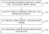
对人体下肢骨骼的医学图像进行图像分割和三维图像重建,得到包含胫骨与腓骨的三维图像;Perform image segmentation and 3D image reconstruction on medical images of human lower limb bones to obtain 3D images including tibia and fibula;
对所述包含胫骨与腓骨的三维图像进行关键点识别,确定胫骨截骨部位的参数信息;Perform key point identification on the three-dimensional image including the tibia and fibula, and determine the parameter information of the tibial osteotomy site;
基于所述参数信息生成截骨导板模型,并获取所述截骨导板模型的数据;generating an osteotomy guide model based on the parameter information, and acquiring data of the osteotomy guide model;
基于所获取的所述截骨导板模型的数据通过3D打印制作胫骨高位截骨导板。Based on the acquired data of the osteotomy guide model, a high tibial osteotomy guide is fabricated by 3D printing.
根据本发明提供的用于胫骨截骨智能导航系统的规划方法,所述基于所述参数信息生成截骨导板模型,包括:According to the planning method for an intelligent navigation system for tibial osteotomy provided by the present invention, generating an osteotomy guide model based on the parameter information includes:
通过第三关键点做胫骨矢状面的第一平行面;Make the first parallel plane of the sagittal plane of the tibia through the third key point;
通过第四关键点做胫骨冠状面的第二平行面;Make the second parallel plane of the coronal plane of the tibia through the fourth key point;
通过第一关键点和第二关键点做胫骨冠状面的第一垂面,使第一截骨面沿所述第一垂面从胫骨内侧截开所述胫骨,并截止于所述第一平行面和所述第二平行面;The first vertical plane of the coronal plane of the tibia is made through the first key point and the second key point, so that the first osteotomy plane cuts the tibia from the inner side of the tibia along the first vertical plane, and ends at the first parallel face and the second parallel face;
通过所述第一垂面与所述第二平行面的交线,与所述第一垂面呈110 ~130°角做第二截骨面,使所述第二截骨面截透所述胫骨前方的内外侧,并截止于所述第一截骨面;Through the intersection of the first vertical plane and the second parallel plane, a second osteotomy surface is formed at an angle of 110 to 130° with the first vertical plane, so that the second osteotomy surface cuts through the The inner and outer sides of the front of the tibia, and ends at the first osteotomy surface;
基于矫正前后下肢力线的位置,确定所述胫骨被所述第一截骨面和所述第二截骨面截开在所述胫骨内部形成的楔形空间角度;Determine the wedge-shaped space angle formed inside the tibia by the tibia being cut by the first osteotomy surface and the second osteotomy surface based on the corrected position of the front and rear lower limb alignment;
基于所述楔形空间角度、所述第一截骨面和所述第二截骨面生成所述截骨导板模型。The osteotomy guide model is generated based on the wedge space angle, the first osteotomy surface and the second osteotomy surface.
根据本发明提供的用于胫骨截骨智能导航系统的规划方法,所述对所述包含胫骨与腓骨的三维图像进行关键点识别,确定胫骨截骨部位的参数信息,包括:According to the planning method for the intelligent navigation system for tibial osteotomy provided by the present invention, the key point identification is performed on the three-dimensional image including the tibia and the fibula, and the parameter information of the tibial osteotomy site is determined, including:
在所述包含胫骨与腓骨的三维图像中,识别腓骨近端与胫骨接触的最高点;将在所述胫骨上与所述最高点接触的点识别为所述参数信息中的所述第一关键点;或者,In the three-dimensional image including the tibia and the fibula, identify the highest point where the proximal end of the fibula contacts the tibia; identify the point on the tibia that is in contact with the highest point as the first key in the parameter information point; or,
在所述包含胫骨与腓骨的三维图像中,识别胫骨平台外侧的最高点;将所述胫骨平台外侧的最高点向下第一预设距离的胫骨截骨位置处识别为所述参数信息中的所述第一关键点;其中,所述第一预设距离的取值大于或等于1.5cm。In the three-dimensional image including the tibia and fibula, identify the highest point on the outer side of the tibial plateau; identify the highest point on the outer side of the tibial plateau at the position of the tibial osteotomy at a first preset distance downward as the parameter in the parameter information. The first key point; wherein, the value of the first preset distance is greater than or equal to 1.5cm.
根据本发明提供的用于胫骨截骨智能导航系统的规划方法,所述对所述包含胫骨与腓骨的三维图像进行关键点识别,确定胫骨截骨部位的参数信息,包括:According to the planning method for the intelligent navigation system for tibial osteotomy provided by the present invention, the key point identification is performed on the three-dimensional image including the tibia and the fibula, and the parameter information of the tibial osteotomy site is determined, including:
对所述包含胫骨与腓骨的三维图像做胫骨的冠状面投影,得到胫骨的冠状面图像;在所得到的胫骨的冠状面图像中,识别胫骨近端最内侧点;以所识别的最内侧点为圆心,以第二预设距离为半径做圆形,将所做的圆形与胫骨内侧的交点识别为所述参数信息中的所述第二关键点;或者,Perform a coronal projection of the tibia on the three-dimensional image including the tibia and fibula to obtain a coronal image of the tibia; in the obtained coronal image of the tibia, identify the innermost point of the proximal tibia; use the identified innermost point be the center of the circle, make a circle with the second preset distance as the radius, and identify the intersection of the circle and the inner side of the tibia as the second key point in the parameter information; or,
在所述包含胫骨与腓骨的三维图像中,识别胫骨平台内侧的最高点;将所述胫骨平台内侧的最高点向下第二预设距离处或者最凹处识别为所述参数信息中的所述第二关键点;其中,所述第二预设距离的取值范围为3cm~4cm。In the three-dimensional image including the tibia and fibula, identify the highest point on the inner side of the tibial plateau; identify the highest point on the inner side of the tibial plateau at a second preset distance or the most concave point as all the parameters in the parameter information. The second key point; wherein, the value range of the second preset distance is 3cm~4cm.
根据本发明提供的用于胫骨截骨智能导航系统的规划方法,所述对所述包含胫骨与腓骨的三维图像进行关键点识别,确定胫骨截骨部位的参数信息,包括:According to the planning method for the intelligent navigation system for tibial osteotomy provided by the present invention, the key point identification is performed on the three-dimensional image including the tibia and the fibula, and the parameter information of the tibial osteotomy site is determined, including:
对所述包含胫骨与腓骨的三维图像做胫骨的冠状面投影,得到胫骨的冠状面图像;Perform a coronal projection of the tibia on the three-dimensional image comprising the tibia and the fibula to obtain a coronal image of the tibia;
在所得到的胫骨的冠状面图像中,识别胫骨近端最外侧点;In the obtained coronal image of the tibia, identify the most lateral point of the proximal tibia;
将所识别的最外侧点向内侧沿图像横轴在与所述最外侧点相距第三预设距离处识别为所述参数信息中的所述第三关键点;其中,所述第三预设距离的取值范围为1cm~1.5cm;Identifying the identified outermost point inward along the horizontal axis of the image at a third preset distance from the outermost point as the third key point in the parameter information; wherein, the third preset The value range of the distance is 1cm~1.5cm;
所述通过第三关键点做胫骨矢状面的第一平行面,包括:The first parallel plane of the sagittal plane of the tibia is made through the third key point, including:
通过所述第三关键点做一条平行于图像纵轴的直线,以所做的直线为所述第一平行面在所述冠状面图像中的投影,确定所述第一平行面。A straight line parallel to the longitudinal axis of the image is drawn through the third key point, and the drawn straight line is used as the projection of the first parallel plane in the coronal plane image to determine the first parallel plane.
根据本发明提供的用于胫骨截骨智能导航系统的规划方法,所述对所述包含胫骨与腓骨的三维图像进行关键点识别,确定胫骨截骨部位的参数信息,包括:According to the planning method for the intelligent navigation system for tibial osteotomy provided by the present invention, the key point identification is performed on the three-dimensional image including the tibia and the fibula, and the parameter information of the tibial osteotomy site is determined, including:
对所述包含胫骨与腓骨的三维图像做胫骨的矢状面投影,得到胫骨的矢状面图像;Perform a sagittal plane projection of the tibia on the three-dimensional image including the tibia and the fibula to obtain a sagittal plane image of the tibia;
在所得到的胫骨的矢状面图像中,识别胫骨近端最前侧点和最后侧点;In the resulting sagittal image of the tibia, identify the most anterior and posterior points of the proximal tibia;
在所识别的最前侧点与最后侧点之间沿图像横轴长度方向的第四预设距离且靠近所述最前侧点处识别为所述参数信息中的所述第四关键点,并识别通过所述第四关键点与所述第五关键点确定的直线在所述矢状面图像中的投影;其中,所述通过第四关键点确定的直线与所述最前侧点和所述最后侧点之间的直线垂直;所述第四预设距离的取值范围为1.5cm~2cm;A fourth preset distance between the identified frontmost point and the rearmost point along the length of the horizontal axis of the image and close to the frontmost point is identified as the fourth key point in the parameter information, and is identified as the fourth key point in the parameter information. The projection of the straight line determined by the fourth key point and the fifth key point in the sagittal plane image; wherein, the straight line determined by the fourth key point and the frontmost point and the last The straight line between the side points is vertical; the value range of the fourth preset distance is 1.5cm~2cm;
所述通过第四关键点做胫骨冠状面的第二平行面,包括:The second parallel plane of the coronal plane of the tibia is made through the fourth key point, including:
通过所识别的直线在所述矢状面图像中的投影做一条平行于图像纵轴的直线,以所做的直线为所述第二平行面在所述矢状面图像中的投影,确定所述第二平行面。A straight line parallel to the longitudinal axis of the image is drawn through the projection of the identified straight line in the sagittal plane image, and the straight line is used as the projection of the second parallel plane in the sagittal plane image to determine the the second parallel plane.
第二方面,本发明还提供一种用于胫骨截骨智能导航系统的规划装置,包括:In a second aspect, the present invention also provides a planning device for an intelligent navigation system for tibial osteotomy, comprising:
图像处理模块,用于对人体下肢骨骼的医学图像进行图像分割和三维图像重建,得到包含胫骨与腓骨的三维图像;The image processing module is used for image segmentation and three-dimensional image reconstruction of medical images of human lower limb bones to obtain three-dimensional images including tibia and fibula;
参数确定模块,用于对所述包含胫骨与腓骨的三维图像进行关键点识别,确定胫骨截骨部位的参数信息;A parameter determination module, used to identify key points on the three-dimensional image including the tibia and fibula, and determine the parameter information of the tibial osteotomy site;
模型生成模块,用于基于所述参数信息生成截骨导板模型,并获取所述截骨导板模型的数据;a model generation module for generating an osteotomy guide model based on the parameter information, and acquiring data of the osteotomy guide model;
导板制作模块,用于基于所获取的所述截骨导板模型的数据通过3D打印制作胫骨高位截骨导板。The guide plate making module is used for making the high tibial osteotomy guide plate by 3D printing based on the acquired data of the osteotomy guide plate model.
第三方面,本发明还提供一种电子设备,包括存储器、处理器及存储在存储器上并可在处理器上运行的计算机程序,所述处理器执行所述程序时实现如上述任一种所述用于胫骨截骨智能导航系统的规划方法的步骤。In a third aspect, the present invention also provides an electronic device, comprising a memory, a processor, and a computer program stored in the memory and running on the processor, when the processor executes the program, the processor implements any of the above Describe the steps of a planning method for an intelligent navigation system for tibial osteotomy.
第四方面,发明还提供一种非暂态计算机可读存储介质,其上存储有计算机程序,该计算机程序被处理器执行时实现如上述任一种所述用于胫骨截骨智能导航系统的规划方法的步骤。In a fourth aspect, the invention also provides a non-transitory computer-readable storage medium on which a computer program is stored, and when the computer program is executed by the processor, the intelligent navigation system for tibial osteotomy as described in any of the above is realized. Steps of the planning method.
第五方面,发明还提供一种计算机程序产品,其上存储有计算机程序,该计算机程序被处理器执行时实现如上述任一种所述用于胫骨截骨智能导航系统的规划方法的步骤。In a fifth aspect, the invention also provides a computer program product, which stores a computer program, and when the computer program is executed by a processor, implements the steps of any of the above-mentioned planning methods for an intelligent navigation system for tibial osteotomy.
本发明提供的用于胫骨截骨智能导航系统的规划方法和装置,通过对人体下肢骨骼的医学图像进行图像分割和三维图像重建,得到包含胫骨与腓骨的三维图像,通过对包含胫骨与腓骨的三维图像进行关键点识别,确定胫骨截骨部位的参数信息,根据所确定的胫骨截骨部位的参数信息生成截骨导板模型,并获取截骨导板模型的数据,根据所获取的截骨导板模型的数据通过3D打印制作胫骨高位截骨导板,可以大幅度减少截骨导板的设计时间,降低设计难度,减少患者手术前等待的时间,可以尽快解决患者的疼痛,可以提高截骨导板设计的准确率,缩短手术的时间,降低手术的风险,实现对患者下肢力线的精准矫正。The planning method and device for an intelligent navigation system for tibial osteotomy provided by the present invention obtain a three-dimensional image including the tibia and fibula by performing image segmentation and three-dimensional image reconstruction on the medical image of the lower limb bones of the human body. The three-dimensional image is used to identify key points, determine the parameter information of the tibial osteotomy site, generate the osteotomy guide model according to the determined parameter information of the tibial osteotomy site, and obtain the data of the osteotomy guide model, according to the obtained osteotomy guide model The 3D printing of the high tibial osteotomy guide can greatly reduce the design time of the osteotomy guide, reduce the design difficulty, reduce the waiting time of patients before surgery, solve the pain of patients as soon as possible, and improve the accuracy of the design of the osteotomy guide. It can shorten the operation time, reduce the risk of operation, and realize the precise correction of the patient's lower limb alignment.
附图说明Description of drawings
为了更清楚地说明本发明或现有技术中的技术方案,下面将对实施例或现有技术描述中所需要使用的附图作一简单地介绍,显而易见地,下面描述中的附图是本发明的一些实施例,对于本领域普通技术人员来讲,在不付出创造性劳动的前提下,还可以根据这些附图获得其他的附图。In order to explain the present invention or the technical solutions in the prior art more clearly, the following will briefly introduce the accompanying drawings that need to be used in the description of the embodiments or the prior art. Obviously, the accompanying drawings in the following description are the For some embodiments of the invention, for those of ordinary skill in the art, other drawings can also be obtained according to these drawings without any creative effort.
图1是本发明提供的用于胫骨截骨智能导航系统的规划方法的流程示意图;1 is a schematic flowchart of a planning method for an intelligent navigation system for tibial osteotomy provided by the present invention;
图2是本发明提供的通过对三维图像进行关键点确定胫骨截骨部位的参数信息的流程示意图;2 is a schematic flowchart of determining the parameter information of the tibial osteotomy site by performing key points on a three-dimensional image provided by the present invention;
图3A至图3K是本发明提供的确定胫骨截骨部位的参数信息以及根据参数信息生成截骨导板模型的示意图;3A to 3K are schematic diagrams of determining parameter information of a tibial osteotomy site provided by the present invention and generating an osteotomy guide model according to the parameter information;
图4是本发明提供的根据胫骨截骨部位的参数信息生成截骨导板模型的流程示意图;4 is a schematic flowchart of generating an osteotomy guide plate model according to the parameter information of the tibial osteotomy site provided by the present invention;
图5A是本发明提供的通过三维图像识别第一关键点的流程示意图;5A is a schematic flowchart of identifying the first key point through a three-dimensional image provided by the present invention;
图5B是采用图5A中的流程识别第一关键点的示意图;5B is a schematic diagram of identifying the first key point using the process in FIG. 5A;
图6A是本发明提供的通过三维图像识别第二关键点的流程示意图;6A is a schematic flowchart of identifying a second key point through a three-dimensional image provided by the present invention;
图6B是采用图6A中的流程识别第二关键点的示意图;6B is a schematic diagram of identifying the second key point using the process in FIG. 6A;
图7A是本发明提供的通过三维图像识别第三关键点并确定第一平行面的流程示意图;7A is a schematic flowchart of identifying the third key point and determining the first parallel plane through a three-dimensional image provided by the present invention;
图7B是采用图7A中的流程识别第三关键点并确定第一平行面的示意图;7B is a schematic diagram of identifying the third key point and determining the first parallel plane using the process in FIG. 7A;
图8A是本发明提供的通过三维图像识别第四关键点与第五关键点确定的直线的投影并确定第二平行面的流程示意图;8A is a schematic flowchart of identifying the projection of the straight line determined by the fourth key point and the fifth key point and determining the second parallel plane through a three-dimensional image provided by the present invention;
图8B是采用图8A中的流程识别第四关键点与第五关键点确定的直线的投影并确定第二平行面的示意图;8B is a schematic diagram of identifying the projection of the straight line determined by the fourth key point and the fifth key point and determining the second parallel plane using the process in FIG. 8A;
图9是本发明提供的胫骨高位截骨导板的制作装置的组成结构示意图;9 is a schematic diagram of the composition of the device for making the high tibial osteotomy guide provided by the present invention;
图10是本发明提供的电子设备的组成结构示意图。FIG. 10 is a schematic diagram of the composition structure of the electronic device provided by the present invention.
具体实施方式Detailed ways
为使本发明的目的、技术方案和优点更加清楚,下面将结合本发明中的附图,对本发明中的技术方案进行清楚、完整地描述,显然,所描述的实施例是本发明一部分实施例,而不是全部的实施例。基于本发明中的实施例,本领域普通技术人员在没有作出创造性劳动前提下所获得的所有其他实施例,都属于本发明保护的范围。In order to make the objectives, technical solutions and advantages of the present invention clearer, the technical solutions in the present invention will be clearly and completely described below with reference to the accompanying drawings. Obviously, the described embodiments are part of the embodiments of the present invention. , not all examples. Based on the embodiments of the present invention, all other embodiments obtained by those of ordinary skill in the art without creative efforts shall fall within the protection scope of the present invention.
下面结合图1-图8B描述本发明的用于胫骨截骨智能导航系统的规划方法。The planning method for the intelligent navigation system for tibial osteotomy of the present invention will be described below with reference to FIGS. 1-8B .
请参阅图1和图2,图1是本发明提供的用于胫骨截骨智能导航系统的规划方法的流程示意图,图1所示的方法可以由用于胫骨截骨智能导航系统的规划装置执行,如图1所示,该用于胫骨截骨智能导航系统的规划方法至少包括:Please refer to FIG. 1 and FIG. 2. FIG. 1 is a schematic flowchart of a planning method for an intelligent navigation system for tibial osteotomy provided by the present invention. The method shown in FIG. 1 can be executed by a planning device for an intelligent navigation system for tibial osteotomy. , as shown in Figure 1, the planning method for the intelligent navigation system for tibial osteotomy at least includes:
101,对人体下肢骨骼的医学图像进行图像分割和三维图像重建,得到包含胫骨与腓骨的三维图像。101. Perform image segmentation and three-dimensional image reconstruction on the medical image of the human lower limb skeleton to obtain a three-dimensional image including the tibia and fibula.
在本发明实施例中,在实施胫骨内侧高位截骨术之前,可以通过医学图像采集设备获取患者人体下肢骨骼的医学图像,本发明实施例对所获取的人体下肢骨骼医学图像的类型以及获取人体下肢骨骼医学图像的实现方式不作限定,例如,可以通过CT机对患者的下肢进行扫描,获取患者下肢骨骼全长的CT图像。在获得人体下肢骨骼的医学图像之后,可以对人体下肢骨骼的医学图像进行图像分割,并对分割后的图像进行三维图像重建,从而得到包含胫骨与腓骨的三维图像,本发明实施例对图像分割和三维图像重建的实现方法不作限定。In this embodiment of the present invention, before performing high medial tibial osteotomy, a medical image of the patient's lower extremity skeleton can be acquired through a medical image acquisition device. The implementation manner of the lower extremity skeleton medical image is not limited, for example, the patient's lower extremity may be scanned by a CT machine to obtain a CT image of the full length of the patient's lower extremity skeleton. After obtaining the medical image of the human lower extremity skeleton, image segmentation can be performed on the medical image of the human lower extremity skeleton, and three-dimensional image reconstruction can be performed on the segmented image, so as to obtain a three-dimensional image including the tibia and fibula. The implementation method of 3D image reconstruction and 3D image reconstruction is not limited.
在一些可选的例子中,可以通过人工智能 (Artificial Intelligence,简称AI)技术对人体下肢骨骼的CT图像进行图像分割,得到包含胫骨与腓骨的图像,然后通过人工智能技术对分割得到的包含胫骨与腓骨的图像进行三维图像重建,得到包含胫骨与腓骨的三维图像。本发明实施例对实现图像分割和三维图像重建所采用的人工智能技术的具体形式不作限定。可选地,可以采用相同的人工智能技术来实现图像分割和三维图像重建,例如,可以采用人工神经网络等机器学习技术;或者也可以采用不同的人工智能技术来实现图像分割、和三维图像重建。In some optional examples, artificial intelligence (Artificial Intelligence, AI for short) technology can be used to perform image segmentation on CT images of human lower extremity bones to obtain images including tibia and fibula, and then artificial intelligence technology can be used to segment the obtained images including tibia Perform three-dimensional image reconstruction with the image of the fibula to obtain a three-dimensional image including the tibia and the fibula. The embodiments of the present invention do not limit the specific form of the artificial intelligence technology used to realize image segmentation and three-dimensional image reconstruction. Optionally, the same artificial intelligence technology can be used to achieve image segmentation and 3D image reconstruction, for example, machine learning technologies such as artificial neural networks can be used; or different artificial intelligence technologies can be used to achieve image segmentation and 3D image reconstruction. .
102,对包含胫骨与腓骨的三维图像进行关键点识别,确定胫骨截骨部位的参数信息。102. Perform key point identification on the three-dimensional image including the tibia and fibula, and determine the parameter information of the tibial osteotomy site.
在本发明实施例中,在对人体下肢骨骼的医学图像进行图像分割及三维图像重建之后,可以根据所得到的包含胫骨与腓骨的三维图像,通过对三维图像进行关键点识别,确定胫骨截骨部位的参数信息,例如,所确定的胫骨截骨部位的参数信息可以是用来规划截骨部位的截骨面和截骨角度的关键点,本发明实施例对所确定的胫骨截骨部位的参数信息的类型以及通过对三维图像进行关键点识别确定截骨部位的参数信息的实现方法不作限定。In the embodiment of the present invention, after image segmentation and three-dimensional image reconstruction are performed on the medical image of the human lower extremity skeleton, the tibia osteotomy can be determined by identifying key points on the three-dimensional image according to the obtained three-dimensional image including the tibia and fibula. The parameter information of the site, for example, the determined parameter information of the tibial osteotomy site may be a key point used to plan the osteotomy surface and the osteotomy angle of the osteotomy site. The type of parameter information and the realization method of determining the parameter information of the osteotomy site by performing key point recognition on the three-dimensional image are not limited.
在一些可选的例子中,可以通过人工智能技术对包含胫骨与腓骨的三维图像进行关键点识别,确定胫骨截骨部位的参数信息。本发明实施例对进行关键点识别所采用的人工智能技术的具体形式不作限定。可选地,可以采用与图像分割和三维图像重建相同的人工智能技术来进行关键点识别,例如,可以采用人工神经网络等机器学习技术;或者也可以采用与图像分割和三维图像重建不同的人工智能技术来进行关键点识别。In some optional examples, artificial intelligence technology can be used to identify key points on the three-dimensional image including the tibia and fibula, and to determine the parameter information of the tibial osteotomy site. The embodiment of the present invention does not limit the specific form of the artificial intelligence technology used for key point identification. Optionally, the same artificial intelligence technology as image segmentation and 3D image reconstruction can be used for key point recognition, for example, machine learning technology such as artificial neural network can be used; or artificial intelligence different from image segmentation and 3D image reconstruction can also be used. Intelligent technology for key point identification.
103,基于参数信息生成截骨导板模型,并获取截骨导板模型的数据。103. Generate an osteotomy guide model based on the parameter information, and acquire data of the osteotomy guide model.
在本发明实施例中,在对包含胫骨与腓骨的三维图像进行关键点识别确定胫骨截骨部位的参数信息之后,可以根据所确定的胫骨截骨部位的参数信息生成截骨导板模型,并根据所生成的截骨导板模型获取截骨导板模型的数据,作为胫骨高位截骨导板的设计数据,用来制作胫骨高位截骨导板,本发明实施例对根据胫骨截骨部位的参数信息生成截骨导板模型的实现方法不作限定,例如,可以根据所确定的胫骨截骨部位的关键点在截骨部位规划截骨面和截骨角度,根据所规划的截骨面和截骨角度生成与所规划的截骨面和截骨角度相适配的截骨导板模型。In the embodiment of the present invention, after key point identification is performed on the three-dimensional image including the tibia and fibula to determine the parameter information of the tibial osteotomy site, the osteotomy guide model can be generated according to the determined parameter information of the tibial osteotomy site, and according to The generated osteotomy guide model obtains the data of the osteotomy guide model, which is used as the design data of the high tibial osteotomy guide to make the high tibial osteotomy guide. In the embodiment of the present invention, the osteotomy is generated according to the parameter information of the tibial osteotomy site. The implementation method of the guide plate model is not limited. For example, the osteotomy surface and the osteotomy angle can be planned at the osteotomy site according to the determined key points of the tibial osteotomy site, and the planned osteotomy surface and the osteotomy angle can be generated and planned. The osteotomy guide plate model adapted to the osteotomy surface and the osteotomy angle.
104,基于所获取的截骨导板模型的数据通过3D打印制作胫骨高位截骨导板。104, based on the acquired data of the osteotomy guide model, fabricate a high tibial osteotomy guide by 3D printing.
在本发明实施例中,在生成截骨导板模型并获取截骨导板模型的数据之后,可以将所获取的截骨导板模型的数据作为胫骨高位截骨导板的设计数据,根据所获取的截骨导板模型的数据通过3D打印来制作胫骨高位截骨导板,本发明实施例对所获取的截骨导板模型的数据的类型不作限定,例如,所获取的截骨导板模型的数据可以包括与截骨面和截骨角度相适配的截骨导板模型的长度、宽度、厚度、夹角以及固定孔的尺寸和位置等数据。In the embodiment of the present invention, after generating the osteotomy guide model and acquiring the data of the osteotomy guide model, the acquired data of the osteotomy guide model can be used as the design data of the high tibial osteotomy guide, according to the obtained osteotomy guide model data. The data of the guide plate model is made by 3D printing to make the high tibial osteotomy guide plate. The embodiment of the present invention does not limit the type of data of the obtained osteotomy guide model. For example, the obtained data of the osteotomy guide model may include the same The length, width, thickness, included angle, size and position of fixation holes of the osteotomy guide model whose surface and osteotomy angle are adapted.
本发明实施例提供的用于胫骨截骨智能导航系统的规划方法,通过对人体下肢骨骼的医学图像进行图像分割和三维图像重建,得到包含胫骨与腓骨的三维图像,通过对包含胫骨与腓骨的三维图像进行关键点识别,确定胫骨截骨部位的参数信息,根据所确定的胫骨截骨部位的参数信息生成截骨导板模型,并获取截骨导板模型的数据,根据所获取的截骨导板模型的数据通过3D打印制作胫骨高位截骨导板,可以大幅度减少截骨导板的设计时间,降低设计难度,减少患者手术前等待的时间,可以尽快解决患者的疼痛,可以提高截骨导板设计的准确率,缩短手术的时间,降低手术的风险,实现对患者下肢力线的精准矫正。The planning method for an intelligent navigation system for tibial osteotomy provided by the embodiment of the present invention obtains a three-dimensional image including the tibia and fibula by performing image segmentation and three-dimensional image reconstruction on the medical image of the human lower extremity skeleton. The three-dimensional image is used to identify key points, determine the parameter information of the tibial osteotomy site, generate the osteotomy guide model according to the determined parameter information of the tibial osteotomy site, and obtain the data of the osteotomy guide model, according to the obtained osteotomy guide model The 3D printing of the high tibial osteotomy guide can greatly reduce the design time of the osteotomy guide, reduce the design difficulty, reduce the waiting time of patients before surgery, solve the pain of patients as soon as possible, and improve the accuracy of the design of the osteotomy guide. It can shorten the operation time, reduce the risk of operation, and realize the precise correction of the patient's lower limb alignment.
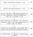
请参阅图2,图2是本发明提供的通过对三维图像进行关键点确定胫骨截骨部位的参数信息的流程示意图,如图2所示,对包含胫骨与腓骨的三维图像进行关键点识别,确定胫骨截骨部位的参数信息至少包括:Please refer to FIG. 2. FIG. 2 is a schematic flowchart of determining the parameter information of the tibial osteotomy site by performing key points on the three-dimensional image provided by the present invention. As shown in FIG. 2, the three-dimensional image including the tibia and the fibula is identified by key points. The parameter information for determining the tibial osteotomy site includes at least:
201,在胫骨平台外侧从最高点向下第一预设距离的胫骨截骨位置处识别第一关键点。201. Identify a first key point at a tibial osteotomy position at a first preset distance downward from the highest point on the outer side of the tibial plateau.
在本发明实施例中,如图3A所示,可以根据患者胫骨上的截骨位置,在三维图像中识别胫骨平台,即胫骨近端,外侧从最高点向下第一预设距离的第一关键点H,也可以称为轴点,其中第一关键点H的位置可以根据患者胫骨上截骨位置的不同而发生变化,例如,第一预设距离的取值范围大于或等于1.5cm,即第一关键点H可以位于胫骨平台外侧从最高点向下至少1.5cm处。本发明实施例对在胫骨平台的外侧识别第一关键点的实现方法不作限定。In the embodiment of the present invention, as shown in FIG. 3A, the tibial plateau, that is, the proximal end of the tibia, can be identified in the three-dimensional image according to the osteotomy position on the patient's tibia, and the outer side is the first predetermined distance from the highest point downward. The key point H may also be referred to as an axis point, wherein the position of the first key point H may vary according to the position of the osteotomy on the patient's tibia, for example, the value range of the first preset distance is greater than or equal to 1.5cm, That is, the first key point H may be located at least 1.5 cm downward from the highest point on the lateral side of the tibial plateau. The embodiment of the present invention does not limit the implementation method of identifying the first key point on the outer side of the tibial plateau.
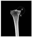
202,在胫骨平台内侧从最高点向下第二预设距离处或者最凹处识别第二关键点。202. Identify a second key point on the inner side of the tibial plateau at a second preset distance or the most concave point downward from the highest point.
在本发明实施例中,如图3A所示,可以在三维图像中识别胫骨平台,即胫骨近端,内侧从最高点向下第二预设距离处或者最凹处的第二关键点A,也可以称为横向截骨点,例如,第二预设距离的取值范围为3cm~4cm,即第二关键点A可以位于胫骨平台内侧从最高点向下至少3cm~4cm处。本发明实施例对在胫骨平台的内侧识别第二关键点的实现方法不作限定。In the embodiment of the present invention, as shown in FIG. 3A , the tibial plateau, that is, the proximal tibia, the inner side of the tibia can be identified from the highest point downward at a second preset distance or the second key point A at the most concave position in the three-dimensional image, It can also be called a transverse osteotomy point. For example, the range of the second preset distance is 3cm~4cm, that is, the second key point A can be located at least 3cm~4cm downward from the highest point on the inner side of the tibial plateau. The embodiment of the present invention does not limit the implementation method of identifying the second key point on the inner side of the tibial plateau.
203,在胫骨平台距离外侧边缘第三预设距离处识别第三关键点。203. Identify a third key point at a third preset distance from the tibial plateau from the lateral edge.
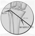
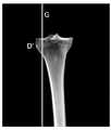
在本发明实施例中,如图3B所示,可以在三维图像中识别胫骨平台,即胫骨近端,距离外侧边缘第三预设距离处的第三关键点D,例如,第三预设距离的取值范围为1cm~1.5cm,即第三关键点D可以位于胫骨平台上,与胫骨平台的外侧相距1cm~1.5cm处。本发明实施例对在胫骨平台上识别第三关键点的实现方法不作限定。In the embodiment of the present invention, as shown in FIG. 3B , the tibial plateau, that is, the proximal end of the tibia, can be identified in the three-dimensional image, and the third key point D at the third preset distance from the lateral edge, for example, the third preset distance The value range of D is 1cm~1.5cm, that is, the third key point D can be located on the tibial plateau, 1cm~1.5cm away from the outer side of the tibial plateau. The embodiments of the present invention do not limit the implementation method of identifying the third key point on the tibial plateau.
204,在胫骨平台中前部第四预设距离处识别第四关键点。204. Identify a fourth key point at a fourth preset distance from the middle-anterior portion of the tibial plateau.
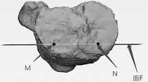
在本发明实施例中,如图3C所示,可以在三维图像中识别胫骨平台,即胫骨近端,中前部第四预设距离处的第四关键点M和N,例如,第四预设距离的取值范围为1.5cm~2cm,即第四关键点M和N可以选取胫骨平台上中前部1.5cm~2cm处的两个点,并使这两个点的连线MN与胫骨冠状面平行。本发明实施例对在胫骨平台上识别第四关键点的实现方法不作限定。In the embodiment of the present invention, as shown in FIG. 3C , the tibial plateau, that is, the proximal end of the tibia, the fourth key points M and N at the fourth preset distance in the front part of the tibia can be identified in the three-dimensional image, for example, the fourth preset distance The value range of the distance is 1.5cm~2cm, that is, the fourth key points M and N can be selected from two points at 1.5cm~2cm in the middle and anterior part of the tibial plateau, and make the connection line MN between these two points and the tibia. The coronal planes are parallel. The embodiments of the present invention do not limit the implementation method of identifying the fourth key point on the tibial plateau.
请参阅图4,图4是本发明提供的根据胫骨截骨部位的参数信息生成截骨导板模型的流程示意图,如图4所示,基于参数信息生成截骨导板模型至少包括:Please refer to FIG. 4. FIG. 4 is a schematic flowchart of generating an osteotomy guide model according to the parameter information of the tibial osteotomy site provided by the present invention. As shown in FIG. 4, generating an osteotomy guide model based on the parameter information at least includes:
401,通过第三关键点做胫骨矢状面的第一平行面。401 , making a first parallel plane of the sagittal plane of the tibia through the third key point.
在本发明实施例中,如图3B所示,在三维图像中识别出胫骨平台上,即胫骨近端,距离外侧边缘第三预设距离处的第三关键点D之后,可以通过第三关键点D做胫骨矢状面的第一平行面G,本发明实施例对通过第三关键点确定第一平行面的实现方法不作限定。In this embodiment of the present invention, as shown in FIG. 3B , after identifying the third key point D on the tibial plateau, that is, the proximal end of the tibia, at a third preset distance from the lateral edge in the three-dimensional image, the third key Point D is the first parallel plane G of the sagittal plane of the tibia, and the embodiment of the present invention does not limit the implementation method of determining the first parallel plane through the third key point.
402,通过第四关键点做胫骨冠状面的第二平行面。402, making a second parallel plane of the coronal plane of the tibia through the fourth key point.
在本发明实施例中,如图3C所示,在三维图像中识别出胫骨平台上,即胫骨近端,中前部第四预设距离处的第四关键点M和N之后,可以通过第四关键点M和N做胫骨冠状面的第二平行面F,例如,通过连线MN生成胫骨冠状面的第二平行面F ,本发明实施例对通过第四关键点确定第二平行面的实现方法不作限定。In the embodiment of the present invention, as shown in FIG. 3C, after identifying the fourth key points M and N at the fourth preset distance on the tibial plateau, that is, the proximal end of the tibia, in the front part of the tibia in the three-dimensional image, the The four key points M and N are used as the second parallel plane F of the coronal tibia. For example, the second parallel plane F of the coronal tibia is generated by connecting line MN. The implementation method is not limited.
403,通过第一关键点和第二关键点做胫骨冠状面的第一垂面,使第一截骨面沿第一垂面从胫骨内侧截开胫骨,并截止于第一平行面和第二平行面。403, making the first vertical plane of the coronal plane of the tibia through the first key point and the second key point, so that the first osteotomy plane cuts the tibia from the inner side of the tibia along the first vertical plane, and ends at the first parallel plane and the second plane. parallel faces.
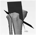
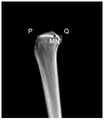
在本发明实施例中,如图3D所示,可以在三维图像中通过第一关键点H和第二关键点A做胫骨冠状面的第一垂面P,使第一截骨面P沿第一垂面E从胫骨内侧截开胫骨,并截止于第一平行面G和第二平行面F,例如,可以通过第一关键点H和第二关键点A的连线HA做胫骨冠状面的第一垂面E,第一垂面E为与胫骨平台保持一定倾斜角度的平面,第一截骨面P沿第一垂面E从胫骨内侧截开胫骨,截透胫骨后侧,不截透胫骨外侧和前侧,截骨深度至第一平行面G和第二平行面F为止。In the embodiment of the present invention, as shown in FIG. 3D, the first vertical plane P of the coronal plane of the tibia can be made through the first key point H and the second key point A in the three-dimensional image, so that the first osteotomy plane P is along the first vertical plane of the tibia. A vertical plane E cuts the tibia from the medial side of the tibia, and ends at the first parallel plane G and the second parallel plane F. For example, the coronal plane of the tibia can be drawn through the connecting line HA between the first key point H and the second key point A. The first vertical plane E, the first vertical plane E is a plane that maintains a certain inclination angle with the tibial plateau, and the first osteotomy plane P cuts the tibia from the inner side of the tibia along the first vertical plane E, cuts through the posterior side of the tibia, and does not cut through the tibia. On the lateral and anterior sides of the tibia, the osteotomy depth reaches the first parallel plane G and the second parallel plane F.
404,通过第一垂面与第二平行面的交线,与第一垂面呈110 ~130°角做第二截骨面,使第二截骨面截透胫骨前方的内外侧,并截止于第一截骨面。404, through the intersection of the first vertical plane and the second parallel plane, make a second osteotomy surface at an angle of 110 to 130° with the first vertical plane, so that the second osteotomy surface cuts through the inner and outer sides of the front of the tibia, and ends on the first osteotomy surface.
在本发明实施例中,如图3E所示,可以在三维图像中通过第一垂面E与第二平行面F的交线L,在与第一垂面E呈110-130°角做第二截骨面Q,使第二截骨面Q截透胫骨前方的内外侧,并截止于第一截骨面P,例如,可以通过第一垂面E与第二平行面F的交线L,在与第一垂面呈110-130°角的方向上做第二截骨面Q,使第二截骨面Q横向截透胫骨前方的内外侧,纵向截骨深度至第一截骨面P为止。其中,第一截骨面P与第二截骨面Q均为平面,In the embodiment of the present invention, as shown in FIG. 3E , in the three-dimensional image, the intersection line L between the first vertical plane E and the second parallel plane F can be used to make the first vertical plane E at an angle of 110-130°. Two osteotomy planes Q, so that the second osteotomy plane Q cuts through the inner and outer sides of the front of the tibia, and ends at the first osteotomy plane P, for example, it can pass through the intersection L of the first vertical plane E and the second parallel plane F , make the second osteotomy surface Q in the direction of 110-130° angle with the first vertical plane, so that the second osteotomy surface Q transversely cuts through the inner and outer sides of the front of the tibia, and the longitudinal osteotomy depth reaches the first osteotomy surface up to P. Among them, the first osteotomy surface P and the second osteotomy surface Q are both planes,
405,基于矫正前后下肢力线的位置,确定胫骨被第一截骨面截和第二截骨面开在胫骨内部形成的楔形空间角度。405. Determine a wedge-shaped space angle formed by the first osteotomy surface and the second osteotomy surface opening the tibia inside the tibia based on the corrected position of the front and rear lower limb alignment.
在本发明实施例中,如图3G和图3H所示,可以通过矫正前后下肢力线位置的变换,计算胫骨被第一截骨面P和第二截骨面Q截开在胫骨内部形成的楔形空间角度α,例如,在胫骨被第一截骨面P和第二截骨面Q截开后,可以通过间隙测量块精准测量在胫骨内部形成的楔形空间角度α。In the embodiment of the present invention, as shown in FIG. 3G and FIG. 3H , by correcting the transformation of the alignment of the front and rear lower limbs, it is possible to calculate the result that the tibia is cut by the first osteotomy surface P and the second osteotomy surface Q inside the tibia. The wedge-shaped space angle α, for example, after the tibia is cut by the first osteotomy surface P and the second osteotomy surface Q, the wedge-shaped space angle α formed inside the tibia can be accurately measured by the gap measurement block.
406,基于楔形空间角度、第一截骨面和第二截骨面生成截骨导板模型。406. Generate an osteotomy guide model based on the wedge-shaped space angle, the first osteotomy surface, and the second osteotomy surface.
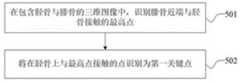
在本发明实施例中,如图3I、图3J和图3K所示,可以根据楔形空间角度α、第一截骨面P和第二截骨面Q生成与楔形空间角度α、第一截骨面P和第二截骨面Q相适配的截骨导板模型,例如,可以根据第一截骨面P和第二截骨面Q生成截骨导板,为满足楔形空间角度α截骨槽的宽度可以1.5mm,所生成的截骨导板与胫骨前侧拟合,并固定于胫骨内侧。请参阅图5A,图5A是本发明提供的通过三维图像识别第一关键点的流程示意图,如图5A所示,在胫骨平台外侧从最高点向下第一预设距离的胫骨截骨位置处识别第一关键点至少包括:In this embodiment of the present invention, as shown in FIGS. 3I , 3J and 3K, the wedge-shaped space angle α, the first osteotomy surface Q and the wedge-shaped space angle α can be generated according to the wedge-shaped space angle α, the first osteotomy surface P and the second osteotomy surface Q The osteotomy guide model with the matching surface P and the second osteotomy surface Q, for example, the osteotomy guide can be generated according to the first osteotomy surface P and the second osteotomy surface Q, in order to meet the requirements of the wedge-shaped space angle α osteotomy groove. The width can be 1.5mm, and the generated osteotomy guide is fitted with the anterior side of the tibia and fixed on the inner side of the tibia. Please refer to FIG. 5A. FIG. 5A is a schematic flowchart of identifying the first key point through a three-dimensional image provided by the present invention. As shown in FIG. 5A, at the tibial osteotomy position at the first preset distance from the highest point on the outside of the tibial plateau Identifying the first key point includes at least:
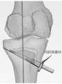
501,在包含胫骨与腓骨的三维图像中,识别腓骨近端与胫骨接触的最高点。501. In the three-dimensional image including the tibia and the fibula, identify the highest point where the proximal end of the fibula contacts the tibia.
502,将在胫骨上与最高点接触的点识别为第一关键点。502. Identify the point on the tibia that is in contact with the highest point as the first key point.
在本发明实施例中,如图5B所示,对于包含胫骨与腓骨的三维图像,可以以左上角为坐标原点,以胫骨外侧到内侧的方向为X轴的正方向,以胫骨前侧到后侧的方向为Y轴的正方向,建立三维直角坐标系。然后计算包含胫骨与腓骨的三维图像中腓骨部分所有像素点的三位直角坐标(x,y,z),对腓骨部分所有像素点的z坐标按照从小到大的顺序进行排列,将其中z坐标最小的点识别为腓骨近端与胫骨接触的最高点H′。在识别出腓骨近端的最高点H′之后,可以将包含胫骨与腓骨的三维图像中胫骨部分与最高点H′接触的点识别为第一关键点H。In this embodiment of the present invention, as shown in FIG. 5B , for a three-dimensional image including the tibia and fibula, the upper left corner can be used as the origin of the coordinates, the direction from the lateral to the medial side of the tibia is the positive direction of the X-axis, and the front side to the back of the tibia can be used as the positive direction of the X-axis. The direction of the side is the positive direction of the Y axis, and a three-dimensional Cartesian coordinate system is established. Then calculate the three-dimensional rectangular coordinates (x, y, z) of all the pixels of the fibula in the three-dimensional image of the tibia and fibula, and arrange the z-coordinates of all the pixels of the fibula in ascending order. The smallest point is identified as the highest point H' where the proximal fibula contacts the tibia. After identifying the highest point H' of the proximal end of the fibula, the point where the part of the tibia is in contact with the highest point H' in the three-dimensional image including the tibia and the fibula can be identified as the first key point H.
请参阅图6A,图6A是本发明提供的通过三维图像识别第二关键点的流程示意图,如图6A所示,在胫骨平台内侧从最高点向下第二预设距离处或者最凹处识别第二关键点至少包括:Please refer to FIG. 6A. FIG. 6A is a schematic flowchart of identifying the second key point through a three-dimensional image provided by the present invention. As shown in FIG. 6A, the second preset distance or the most concave point is identified on the inner side of the tibial plateau from the highest point downward. The second key point includes at least:
601,对包含胫骨与腓骨的三维图像做胫骨的冠状面投影,得到胫骨的冠状面图像。601. Perform a coronal projection of the tibia on the three-dimensional image including the tibia and the fibula to obtain a coronal image of the tibia.
602,在所得到的胫骨的冠状面图像中,识别胫骨近端最内侧点。602. In the obtained coronal image of the tibia, identify the innermost point of the proximal tibia.
603,以所识别的最内侧点为圆心,以第二预设距离为半径做圆形,将所做的圆形与胫骨内侧的交点识别为第二关键点。603. Use the identified innermost point as the center of the circle, and use the second preset distance as the radius to make a circle, and identify the intersection of the circle and the inner side of the tibia as the second key point.
在本发明实施例中,如图6B所示,可以对包含胫骨与腓骨的三维图像做胫骨的冠状面投影,得到胫骨的冠状面图像,可以以冠状面图像左上角为坐标原点,以图像横轴方向为X轴的正方向,以图像纵轴方向为Z轴的正方向,建立二维直角坐标系。然后计算冠状面图像上胫骨部分所有像素点的x坐标,并按照从大到小的顺序进行排列,将其中x坐标最大的点识别为胫骨最内侧点A’。在识别出胫骨最内侧点A’之后,以胫骨最内侧点A’为圆心,以第二预设距离为半径画圆形,例如第二预设距离为30mm,将所画的圆形在冠状面图像中与胫骨内侧的交点识别为第二关键点A。In the embodiment of the present invention, as shown in FIG. 6B , the coronal plane projection of the tibia can be performed on the three-dimensional image including the tibia and the fibula to obtain the coronal plane image of the tibia. The axis direction is the positive direction of the X axis, and the vertical axis direction of the image is the positive direction of the Z axis to establish a two-dimensional Cartesian coordinate system. Then, the x-coordinates of all the pixels of the tibia on the coronal image are calculated and arranged in descending order, and the point with the largest x-coordinate is identified as the innermost point A' of the tibia. After identifying the innermost point A' of the tibia, draw a circle with the innermost point A' of the tibia as the center and a second preset distance as the radius, for example, the second preset distance is 30mm, and place the drawn circle on the coronal The intersection with the inner side of the tibia in the face image is identified as the second key point A.
请参阅图7A,图7A是本发明提供的通过三维图像识别第三关键点并确定第一平行面的流程示意图,如图7A所示,在胫骨平台距离外侧边缘第三预设距离处识别第三关键点,通过第三关键点做胫骨矢状面的第一平行面至少包括:Please refer to FIG. 7A . FIG. 7A is a schematic flowchart of identifying the third key point and determining the first parallel plane through a three-dimensional image provided by the present invention. As shown in FIG. 7A , the third preset distance from the tibial plateau to the outer edge is identified Three key points, the first parallel plane of the sagittal plane of the tibia through the third key point includes at least:
701,对包含胫骨与腓骨的三维图像做胫骨的冠状面投影,得到胫骨的冠状面图像。701. Perform a coronal projection of the tibia on the three-dimensional image including the tibia and the fibula to obtain a coronal image of the tibia.
702,在所得到的胫骨的冠状面图像中,识别胫骨近端最外侧点。702. In the obtained coronal image of the tibia, identify the outermost point of the proximal tibia.
703,从所识别的最外侧点向内侧沿图像横轴在与最外侧点相距第三预设距离处识别第三关键点。703. Identify a third key point at a third preset distance from the outermost point along the horizontal axis of the image from the identified outermost point to the inner side.
704,通过第三关键点做一条平行于图像纵轴的直线,以所做的直线为第一平行面在冠状面图像中的投影,确定第一平行面。704. Draw a straight line parallel to the longitudinal axis of the image through the third key point, and use the drawn straight line as the projection of the first parallel plane on the coronal plane image to determine the first parallel plane.
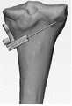
在本发明实施例中,如图7B所示,可以对包含胫骨与腓骨的三维图像做胫骨的冠状面投影,得到胫骨的冠状面图像,可以以冠状面图像左上角为坐标原点,以图像横轴方向为X轴的正方向,以图像纵轴方向为Z轴的正方向,建立二维直角坐标系。然后计算冠状面图像上胫骨部分所有像素点的x坐标,并按照从小到大的顺序进行排列,将其中x坐标最小的点识别为胫骨最外侧点D’。在识别出胫骨最外侧点D’之后,将从D’点向胫骨内侧沿图像横轴移动第三预设距离处胫骨上的点识别为第三关键点D,例如第三预设距离为1cm。通过第三关键点D做一条平行于图像纵轴的直线,以这条直线作为第一平行面G在冠状面图像中的投影,来确定第一平行面G。In the embodiment of the present invention, as shown in FIG. 7B , the coronal plane projection of the tibia can be performed on the three-dimensional image including the tibia and the fibula to obtain the coronal plane image of the tibia. The axis direction is the positive direction of the X axis, and the vertical axis direction of the image is the positive direction of the Z axis to establish a two-dimensional Cartesian coordinate system. Then calculate the x-coordinates of all the pixels of the tibia on the coronal image, and arrange them in ascending order, and identify the point with the smallest x-coordinate as the outermost point D' of the tibia. After identifying the outermost point D' of the tibia, the point on the tibia where the point D' is moved to the inner side of the tibia by a third preset distance along the horizontal axis of the image is identified as the third key point D, for example, the third preset distance is 1cm . A straight line parallel to the longitudinal axis of the image is drawn through the third key point D, and the straight line is used as the projection of the first parallel plane G in the coronal plane image to determine the first parallel plane G.
请参阅图8A,图8A是本发明提供的通过三维图像识别第四关键点与第五关键点确定的直线的投影并确定第二平行面的流程示意图,如图8A所示,在胫骨平台中前部第四预设距离处识别第四关键点和第五关键点,通过第四关键点和第五关键点做胫骨冠状面第二平行面至少包括:Please refer to FIG. 8A. FIG. 8A is a schematic flowchart of identifying the projection of the straight line determined by the fourth key point and the fifth key point through the three-dimensional image provided by the present invention and determining the second parallel plane. As shown in FIG. 8A, in the tibial plateau Identify the fourth key point and the fifth key point at the fourth preset distance in the front, and make the second parallel plane of the coronal plane of the tibia through the fourth key point and the fifth key point, including at least:
801,对包含胫骨与腓骨的三维图像做胫骨的矢状面投影,得到胫骨的矢状面图像。801. Perform a sagittal plane projection of the tibia on the three-dimensional image including the tibia and the fibula to obtain a sagittal plane image of the tibia.
802,在所得到的胫骨的矢状面图像中,识别胫骨近端最前侧点和最后侧点。802. In the obtained sagittal image of the tibia, identify the most anterior and posterior points of the proximal tibia.
803,在所识别的最前侧点与最后侧点之间沿图像横轴长度的第四预设距离处且靠近最前侧点处识别第四关键点,并识别通过第四关键点确定的直线在矢状面图像中的投影。803: Identify a fourth key point at a fourth preset distance along the length of the horizontal axis of the image between the identified foremost point and the rearmost point, and identify a fourth keypoint at a position close to the foremost point, and identify the straight line determined by the fourth keypoint at Projection in sagittal image.
804,通过所识别的直线在矢状面图像中的投影做一条平行于图像纵轴的直线,以所做的直线为第二平行面在矢状面图像中的投影,确定第二平行面。804. Create a straight line parallel to the longitudinal axis of the image through the projection of the identified straight line in the sagittal plane image, and determine the second parallel plane by using the straight line as the projection of the second parallel plane in the sagittal plane image.
在本发明实施例中,如图8B所示,可以对包含胫骨与腓骨的三维图像做胫骨的矢状面投影,得到胫骨的矢状面图像,可以以矢状面图像右上角为坐标原点,以图像横轴方向为Y轴的正方向,以图像纵轴方向为Z轴的正方向,建立二维直角坐标系。然后计算矢状面图像上胫骨部分所有像素点的y坐标,并按照从小到大的顺序进行排列,将其中y坐标最小的点识别为胫骨最前侧点P,将其中y坐标最大的点识别为胫骨最后侧点Q。在识别出胫骨最前侧点P和胫骨最后侧点Q之后,计算沿图像横轴胫骨最前侧点P与胫骨最后侧点Q之间的距离h,将位于Q点左侧第四预设距离*h处胫骨上的点识别为第四关键点M和N的连线MN在矢状面图像中的投影,例如第四预设距离为1/3。通过连线MN在矢状面图像中的投影做一条平行于图像纵轴的直线,以这条直线作为第二平行面F在矢状面图像中的投影,来确定第二平行面F。In the embodiment of the present invention, as shown in FIG. 8B , the sagittal plane projection of the tibia can be performed on the three-dimensional image including the tibia and the fibula to obtain the sagittal plane image of the tibia, and the upper right corner of the sagittal plane image can be used as the coordinate origin, Taking the horizontal axis of the image as the positive direction of the Y-axis, and taking the vertical axis of the image as the positive direction of the Z-axis, a two-dimensional Cartesian coordinate system is established. Then calculate the y-coordinates of all the pixels of the tibia on the sagittal plane image, and arrange them in ascending order. The point with the smallest y-coordinate is identified as the most anterior point P of the tibia, and the point with the largest y-coordinate is identified as Q at the rearmost lateral point of the tibia. After identifying the most anterior point P of the tibia and the posterior point Q of the tibia, calculate the distance h between the most anterior point P of the tibia and the posterior point Q of the tibia along the horizontal axis of the image, which will be located at the fourth preset distance to the left of the Q point* The point on the tibia at h is identified as the projection of the connecting line MN of the fourth key points M and N in the sagittal plane image, for example, the fourth preset distance is 1/3. The second parallel plane F is determined by drawing a straight line parallel to the longitudinal axis of the image by connecting the projection of the line MN in the sagittal plane image, and using this straight line as the projection of the second parallel plane F in the sagittal plane image.
下面对本发明提供的用于胫骨截骨智能导航系统的规划装置进行描述,下文描述的用于胫骨截骨智能导航系统的规划装置与上文描述的用于胫骨截骨智能导航系统的规划方法可相互对应参照。The following describes the planning device for the intelligent navigation system for tibial osteotomy provided by the present invention. The planning device for the intelligent navigation system for tibial osteotomy described below and the planning method for the intelligent navigation system for tibial osteotomy described above can be used together. refer to each other.
请参阅图9,图9是本发明提供的用于胫骨截骨智能导航系统的规划装置的组成结构示意图,图9所示的用于胫骨截骨智能导航系统的规划装置可用来执行图1的用于胫骨截骨智能导航系统的规划方法,如图9所示,该用于胫骨截骨智能导航系统的规划装置至少包括:Please refer to FIG. 9, FIG. 9 is a schematic diagram of the composition of the planning device for the intelligent navigation system for tibial osteotomy provided by the present invention, and the planning device for the intelligent navigation system for tibial osteotomy shown in FIG. A planning method for an intelligent navigation system for tibial osteotomy, as shown in Figure 9, the planning device for an intelligent navigation system for tibial osteotomy at least includes:
图像处理模块910,用于对人体下肢骨骼的医学图像进行图像分割和三维图像重建,得到包含胫骨与腓骨的三维图像。The
参数确定模块920,用于对包含胫骨与腓骨的三维图像进行关键点识别,确定胫骨截骨部位的参数信息。The
模型生成模块930,用于基于参数信息生成截骨导板模型,并获取截骨导板模型的数据。The
导板制作模块940,用于基于所获取的截骨导板模型的数据通过3D打印制作胫骨高位截骨导板。The guide
可选地,模型生成模块930包括:Optionally, the
第一平行面生成单元,用于通过第三关键点做胫骨矢状面的第一平行面。The first parallel plane generating unit is used to create the first parallel plane of the sagittal plane of the tibia through the third key point.
第二平行面生成单元,用于通过第四关键点做胫骨冠状面的第二平行面。The second parallel plane generating unit is used to create the second parallel plane of the coronal plane of the tibia through the fourth key point.
第一截骨面生成单元,用于通过第一关键点和第二关键点做胫骨冠状面的第一垂面,使第一截骨面沿第一垂面从胫骨内侧截开胫骨,并截止于第一平行面和第二平行面。The first osteotomy plane generating unit is used to make the first vertical plane of the coronal plane of the tibia through the first key point and the second key point, so that the first osteotomy plane cuts the tibia from the inner side of the tibia along the first vertical plane, and cuts off the tibia. on the first parallel plane and the second parallel plane.
第二截骨面生成单元,用于通过第一垂面与第二平行面的交线,与第一垂面呈110~130°角做第二截骨面,使第二截骨面截透胫骨前方的内外侧,并截止于第一截骨面。The second osteotomy surface generating unit is used to form a second osteotomy surface at an angle of 110-130° with the first vertical surface through the intersection of the first vertical surface and the second parallel surface, so that the second osteotomy surface can be cut through The medial and lateral aspect of the anterior aspect of the tibia, ending at the first osteotomy surface.
楔形空间角度生成单元,用于基于矫正前后下肢力线的位置,确定胫骨被第一截骨面和第二截骨面截开在胫骨内部形成的楔形空间角度。The wedge-shaped space angle generation unit is used for determining the wedge-shaped space angle formed by the first osteotomy surface and the second osteotomy surface cutting the tibia inside the tibia based on the position of the alignment of the lower limb before and after the correction.
截骨导板模型生成单元,用于基于楔形空间角度、第一截骨面和第二截骨面生成截骨导板模型。The osteotomy guide model generation unit is used to generate the osteotomy guide model based on the wedge space angle, the first osteotomy surface and the second osteotomy surface.
可选地,参数确定模块920包括:Optionally, the
第一关键点识别单元,用于在包含胫骨与腓骨的三维图像中,识别腓骨近端与胫骨接触的最高点;将在胫骨上与最高点接触的点识别为参数信息中的第一关键点;或者,The first key point identification unit is used for identifying the highest point where the proximal end of the fibula is in contact with the tibia in the three-dimensional image including the tibia and the fibula; identifying the point on the tibia that is in contact with the highest point as the first key point in the parameter information ;or,
在包含胫骨与腓骨的三维图像中,识别胫骨平台外侧的最高点;将胫骨平台外侧的最高点向下第一预设距离的胫骨截骨位置处识别为参数信息中的第一关键点;其中,第一预设距离的取值大于或等于1.5cm。In the three-dimensional image including the tibia and fibula, identify the highest point on the outer side of the tibial plateau; identify the highest point on the outer side of the tibial plateau at the position of the tibial osteotomy at a first preset distance downward as the first key point in the parameter information; wherein , the value of the first preset distance is greater than or equal to 1.5cm.
可选地,参数确定模块920包括:Optionally, the
第二关键点识别单元,用于对包含胫骨与腓骨的三维图像做胫骨的冠状面投影,得到胫骨的冠状面图像;在所得到的胫骨的冠状面图像中,识别胫骨近端最内侧点;以所识别的最内侧点为圆心,以第二预设距离为半径做圆形,将所做的圆形与胫骨内侧的交点识别为参数信息中的第二关键点;或者,The second key point identification unit is used to project the coronal plane of the tibia on the three-dimensional image including the tibia and the fibula to obtain the coronal plane image of the tibia; in the obtained coronal plane image of the tibia, identify the innermost point of the proximal tibia; Taking the identified innermost point as the center of the circle, making a circle with the second preset distance as the radius, and identifying the intersection of the circle and the inner side of the tibia as the second key point in the parameter information; or,
在包含胫骨与腓骨的三维图像中,识别胫骨平台内侧的最高点;将胫骨平台内侧的最高点向下第二预设距离处或者最凹处识别为参数信息中的第二关键点;其中,第二预设距离的取值范围为3cm~4cm。In the three-dimensional image including the tibia and fibula, identify the highest point on the inner side of the tibial plateau; identify the highest point on the inner side of the tibial plateau at a second preset distance or the most concave point as the second key point in the parameter information; wherein, The value range of the second preset distance is 3cm~4cm.
可选地,参数确定模块920包括:Optionally, the
第三关键点识别单元,用于对包含胫骨与腓骨的三维图像做胫骨的冠状面投影,得到胫骨的冠状面图像;在所得到的胫骨的冠状面图像中,识别胫骨近端最外侧点;将所识别的最外侧点向内侧沿图像横轴在与最外侧点相距第三预设距离处识别为参数信息中的第三关键点;其中,第三预设距离的取值范围为1cm~1.5cm。The third key point identification unit is used to project the coronal plane of the tibia on the three-dimensional image including the tibia and the fibula to obtain the coronal plane image of the tibia; in the obtained coronal plane image of the tibia, identify the outermost point of the proximal tibia; The identified outermost point is identified as the third key point in the parameter information along the horizontal axis of the image at the third preset distance from the outermost point; wherein, the value range of the third preset distance is 1cm~ 1.5cm.
第一平行面生成单元,用于通过第三关键点做一条平行于图像纵轴的直线,以所做的直线为第一平行面在冠状面图像中的投影,确定第一平行面。The first parallel plane generating unit is used to draw a straight line parallel to the longitudinal axis of the image through the third key point, and the drawn straight line is used as the projection of the first parallel plane in the coronal plane image to determine the first parallel plane.
可选地,参数确定模块920包括:Optionally, the
第四关键点识别单元,用于对包含胫骨与腓骨的三维图像做胫骨的矢状面投影,得到胫骨的矢状面图像;在所得到的胫骨的矢状面图像中,识别胫骨近端最前侧点和最后侧点;在所识别的最前侧点与最后侧点之间沿图像横轴长度方向的第四预设距离且靠近最前侧点处识别为参数信息中的第四关键点,并识别通过第四关键点确定的直线在矢状面图像中的投影,其中,通过第四关键点确定的直线与最前侧点和最后侧点之间的直线垂直;第四预设距离的取值范围为1.5cm~2cm。The fourth key point identification unit is used to project the sagittal plane of the tibia on the three-dimensional image including the tibia and the fibula to obtain the sagittal plane image of the tibia; in the obtained sagittal plane image of the tibia, identify the most anterior tibia proximal end Side point and rearmost point; the fourth preset distance between the identified frontmost point and the rearmost point along the length direction of the horizontal axis of the image and close to the frontmost point is identified as the fourth key point in the parameter information, and Identify the projection of the straight line determined by the fourth key point in the sagittal image, wherein the straight line determined by the fourth key point is perpendicular to the straight line between the most anterior point and the posterior point; the value of the fourth preset distance The range is 1.5cm~2cm.
第二平行面生成单元,用于通过所识别的直线在矢状面图像中的投影做一条平行于图像纵轴的直线,以所做的直线为第二平行面在矢状面图像中的投影,确定第二平行面。The second parallel plane generating unit is configured to create a straight line parallel to the longitudinal axis of the image through the projection of the identified straight line in the sagittal plane image, and use the straight line as the projection of the second parallel plane in the sagittal plane image , to determine the second parallel plane.
图10示例了一种电子设备的实体结构示意图,如图10所示,该电子设备可以包括:处理器(processor)1010、通信接口(CommunicationsInterface)1020、存储器(memory)1030和通信总线1040,其中,处理器1010,通信接口1020,存储器1030通过通信总线1040完成相互间的通信。处理器1010可以调用存储器1030中的逻辑指令,以执行用于胫骨截骨智能导航系统的规划方法,该方法包括:FIG. 10 illustrates a schematic diagram of the physical structure of an electronic device. As shown in FIG. 10 , the electronic device may include: a processor (processor) 1010, a communication interface (CommunicationsInterface) 1020, a memory (memory) 1030 and a
对人体下肢骨骼的医学图像进行图像分割和三维图像重建,得到包含胫骨与腓骨的三维图像;Perform image segmentation and 3D image reconstruction on medical images of human lower limb bones to obtain 3D images including tibia and fibula;
对所述包含胫骨与腓骨的三维图像进行关键点识别,确定胫骨截骨部位的参数信息;Perform key point identification on the three-dimensional image including the tibia and fibula, and determine the parameter information of the tibial osteotomy site;
基于所述参数信息生成截骨导板模型,并获取所述截骨导板模型的数据;generating an osteotomy guide model based on the parameter information, and acquiring data of the osteotomy guide model;
基于所获取的所述截骨导板模型的数据通过3D打印制作胫骨高位截骨导板。Based on the acquired data of the osteotomy guide model, a high tibial osteotomy guide is fabricated by 3D printing.
此外,上述的存储器1030中的逻辑指令可以通过软件功能单元的形式实现并作为独立的产品销售或使用时,可以存储在一个计算机可读取存储介质中。基于这样的理解,本发明的技术方案本质上或者说对现有技术做出贡献的部分或者该技术方案的部分可以以软件产品的形式体现出来,该计算机软件产品存储在一个存储介质中,包括若干指令用以使得一台计算机设备(可以是个人计算机,服务器,或者网络设备等)执行本发明各个实施例所述方法的全部或部分步骤。而前述的存储介质包括:U盘、移动硬盘、只读存储器(ROM,Read-OnlyMemory)、随机存取存储器(RAM,RandomAccessMemory)、磁碟或者光盘等各种可以存储程序代码的介质。In addition, the above-mentioned logic instructions in the
另一方面,本发明还提供一种计算机程序产品,所述计算机程序产品包括存储在非暂态计算机可读存储介质上的计算机程序,所述计算机程序包括程序指令,当所述程序指令被计算机执行时,计算机能够执行上述各方法实施例提供的用于胫骨截骨智能导航系统的规划方法,该方法包括:In another aspect, the present invention also provides a computer program product, the computer program product comprising a computer program stored on a non-transitory computer-readable storage medium, the computer program comprising program instructions, when the program instructions are executed by a computer When executed, the computer can execute the planning method for the intelligent navigation system for tibial osteotomy provided by the above method embodiments, and the method includes:
对人体下肢骨骼的医学图像进行图像分割和三维图像重建,得到包含胫骨与腓骨的三维图像;Perform image segmentation and 3D image reconstruction on medical images of human lower limb bones to obtain 3D images including tibia and fibula;
对所述包含胫骨与腓骨的三维图像进行关键点识别,确定胫骨截骨部位的参数信息;Perform key point identification on the three-dimensional image including the tibia and fibula, and determine the parameter information of the tibial osteotomy site;
基于所述参数信息生成截骨导板模型,并获取所述截骨导板模型的数据;generating an osteotomy guide model based on the parameter information, and acquiring data of the osteotomy guide model;
基于所获取的所述截骨导板模型的数据通过3D打印制作胫骨高位截骨导板。Based on the acquired data of the osteotomy guide model, a high tibial osteotomy guide is fabricated by 3D printing.
又一方面,本发明还提供一种非暂态计算机可读存储介质,其上存储有计算机程序,该计算机程序被处理器执行时实现以执行上述各方法实施例提供的用于胫骨截骨智能导航系统的规划方法,该方法包括:In another aspect, the present invention also provides a non-transitory computer-readable storage medium on which a computer program is stored, and when the computer program is executed by a processor, it is implemented to execute the intelligence for tibial osteotomy provided by the above method embodiments. A planning method for a navigation system, the method comprising:
对人体下肢骨骼的医学图像进行图像分割和三维图像重建,得到包含胫骨与腓骨的三维图像;Perform image segmentation and 3D image reconstruction on medical images of human lower limb bones to obtain 3D images including tibia and fibula;
对所述包含胫骨与腓骨的三维图像进行关键点识别,确定胫骨截骨部位的参数信息;Perform key point identification on the three-dimensional image including the tibia and fibula, and determine the parameter information of the tibial osteotomy site;
基于所述参数信息生成截骨导板模型,并获取所述截骨导板模型的数据;generating an osteotomy guide model based on the parameter information, and acquiring data of the osteotomy guide model;
基于所获取的所述截骨导板模型的数据通过3D打印制作胫骨高位截骨导板。Based on the acquired data of the osteotomy guide model, a high tibial osteotomy guide is fabricated by 3D printing.
以上所描述的装置实施例仅仅是示意性的,其中所述作为分离部件说明的单元可以是或者也可以不是物理上分开的,作为单元显示的部件可以是或者也可以不是物理单元,即可以位于一个地方,或者也可以分布到多个网络单元上。可以根据实际的需要选择其中的部分或者全部模块来实现本实施例方案的目的。本领域普通技术人员在不付出创造性的劳动的情况下,即可以理解并实施。The device embodiments described above are only illustrative, wherein the units described as separate components may or may not be physically separated, and the components shown as units may or may not be physical units, that is, they may be located in One place, or it can be distributed over multiple network elements. Some or all of the modules may be selected according to actual needs to achieve the purpose of the solution in this embodiment. Those of ordinary skill in the art can understand and implement it without creative effort.
通过以上的实施方式的描述,本领域的技术人员可以清楚地了解到各实施方式可借助软件加必需的通用硬件平台的方式来实现,当然也可以通过硬件。基于这样的理解,上述技术方案本质上或者说对现有技术做出贡献的部分可以以软件产品的形式体现出来,该计算机软件产品可以存储在计算机可读存储介质中,如ROM/RAM、磁碟、光盘等,包括若干指令用以使得一台计算机设备(可以是个人计算机,服务器,或者网络设备等)执行各个实施例或者实施例的某些部分所述的方法。From the description of the above embodiments, those skilled in the art can clearly understand that each embodiment can be implemented by means of software plus a necessary general hardware platform, and certainly can also be implemented by hardware. Based on this understanding, the above-mentioned technical solutions can be embodied in the form of software products in essence or the parts that make contributions to the prior art, and the computer software products can be stored in computer-readable storage media, such as ROM/RAM, magnetic A disc, an optical disc, etc., includes several instructions for causing a computer device (which may be a personal computer, a server, or a network device, etc.) to perform the methods described in various embodiments or some parts of the embodiments.
最后应说明的是:以上实施例仅用以说明本发明的技术方案,而非对其限制;尽管参照前述实施例对本发明进行了详细的说明,本领域的普通技术人员应当理解:其依然可以对前述各实施例所记载的技术方案进行修改,或者对其中部分技术特征进行等同替换;而这些修改或者替换,并不使相应技术方案的本质脱离本发明各实施例技术方案的精神和范围。Finally, it should be noted that the above embodiments are only used to illustrate the technical solutions of the present invention, but not to limit them; although the present invention has been described in detail with reference to the foregoing embodiments, those of ordinary skill in the art should understand that it can still be The technical solutions described in the foregoing embodiments are modified, or some technical features thereof are equivalently replaced; and these modifications or replacements do not make the essence of the corresponding technical solutions deviate from the spirit and scope of the technical solutions of the embodiments of the present invention.
Claims (8)
Priority Applications (2)
| Application Number | Priority Date | Filing Date | Title |
|---|---|---|---|
| CN202210642831.3ACN114723897B (en) | 2022-06-09 | 2022-06-09 | Planning method and device for intelligent tibial osteotomy navigation system |
| PCT/CN2022/115316WO2023236367A1 (en) | 2022-06-09 | 2022-08-26 | Planning method and apparatus for tibia osteotomy intelligent navigation system |
Applications Claiming Priority (1)
| Application Number | Priority Date | Filing Date | Title |
|---|---|---|---|
| CN202210642831.3ACN114723897B (en) | 2022-06-09 | 2022-06-09 | Planning method and device for intelligent tibial osteotomy navigation system |
Publications (2)
| Publication Number | Publication Date |
|---|---|
| CN114723897A CN114723897A (en) | 2022-07-08 |
| CN114723897Btrue CN114723897B (en) | 2022-08-30 |
Family
ID=82232418
Family Applications (1)
| Application Number | Title | Priority Date | Filing Date |
|---|---|---|---|
| CN202210642831.3AActiveCN114723897B (en) | 2022-06-09 | 2022-06-09 | Planning method and device for intelligent tibial osteotomy navigation system |
Country Status (2)
| Country | Link |
|---|---|
| CN (1) | CN114723897B (en) |
| WO (1) | WO2023236367A1 (en) |
Families Citing this family (5)
| Publication number | Priority date | Publication date | Assignee | Title |
|---|---|---|---|---|
| CN114723897B (en)* | 2022-06-09 | 2022-08-30 | 北京长木谷医疗科技有限公司 | Planning method and device for intelligent tibial osteotomy navigation system |
| CN115153836B (en)* | 2022-07-21 | 2025-02-11 | 武汉理工大学 | A 3D osteotomy preoperative intelligent planning method and system |
| CN115607286B (en)* | 2022-12-20 | 2023-03-17 | 北京维卓致远医疗科技发展有限责任公司 | Knee joint replacement surgery navigation method, system and equipment based on binocular calibration |
| CN117860380B (en)* | 2024-03-11 | 2024-07-30 | 北京壹点灵动科技有限公司 | Data processing method and device for knee joint replacement, storage medium and electronic equipment |
| CN118319484A (en)* | 2024-03-22 | 2024-07-12 | 北京长木谷医疗科技股份有限公司 | Orthopedic surgery robot navigation and positioning method and system |
Citations (2)
| Publication number | Priority date | Publication date | Assignee | Title |
|---|---|---|---|---|
| CN108478250A (en)* | 2018-04-04 | 2018-09-04 | 重庆医科大学附属第医院 | Femur localization method, individuation osteotomy guide plate and the prosthese of total knee arthroplasty |
| CN113919020A (en)* | 2021-09-24 | 2022-01-11 | 北京长木谷医疗科技有限公司 | Guide plate design method for unicondylar replacement and related equipment |
Family Cites Families (4)
| Publication number | Priority date | Publication date | Assignee | Title |
|---|---|---|---|---|
| US9801601B2 (en)* | 2015-12-29 | 2017-10-31 | Laboratoires Bodycad Inc. | Method and system for performing multi-bone segmentation in imaging data |
| CN113116520A (en)* | 2019-12-30 | 2021-07-16 | 上海昕健医疗技术有限公司 | Preoperative planning method for high tibial osteotomy and construction method of guide plate model thereof |
| CN112914724B (en)* | 2021-01-29 | 2022-02-11 | 北京长木谷医疗科技有限公司 | Design method and related equipment of surgical guide for total knee replacement |
| CN114723897B (en)* | 2022-06-09 | 2022-08-30 | 北京长木谷医疗科技有限公司 | Planning method and device for intelligent tibial osteotomy navigation system |
- 2022
- 2022-06-09CNCN202210642831.3Apatent/CN114723897B/enactiveActive
- 2022-08-26WOPCT/CN2022/115316patent/WO2023236367A1/ennot_activeCeased
Patent Citations (2)
| Publication number | Priority date | Publication date | Assignee | Title |
|---|---|---|---|---|
| CN108478250A (en)* | 2018-04-04 | 2018-09-04 | 重庆医科大学附属第医院 | Femur localization method, individuation osteotomy guide plate and the prosthese of total knee arthroplasty |
| CN113919020A (en)* | 2021-09-24 | 2022-01-11 | 北京长木谷医疗科技有限公司 | Guide plate design method for unicondylar replacement and related equipment |
Non-Patent Citations (3)
| Title |
|---|
| Posterior cortical breakage leads to posterior tibial slope change in lateral hinge fracture following opening wedge high tibial osteotomy;Sung‑Sahn Lee 等;《Knee Surgery, Sports Traumatology, Arthroscopy》;20181230;全文* |
| 基于深度学习的膝关节CT 图像自动分割准确性验证研究;宋平 等;《医工融合》;20220531;全文* |
| 计算机辅助设计与3D 打印个性化截骨导板辅助人工全膝关节置换术的精准度研究;刘帅 等;《中国骨与关节损伤杂志》;20170630;第32卷(第6期);全文* |
Also Published As
| Publication number | Publication date |
|---|---|
| CN114723897A (en) | 2022-07-08 |
| WO2023236367A1 (en) | 2023-12-14 |
Similar Documents
| Publication | Publication Date | Title |
|---|---|---|
| CN114723897B (en) | Planning method and device for intelligent tibial osteotomy navigation system | |
| CN112842529B (en) | Total knee joint image processing method and device | |
| CN110215281B (en) | Femur or tibia registration method and device based on total knee replacement surgery | |
| CN110613469B (en) | A kind of automatic detection method and device of leg bone lower limb force line | |
| CN104546060B (en) | Patella osteotomy navigation template for knee arthroplasty and manufacture method | |
| WO2022161161A1 (en) | Smart guide plate design method and device for total knee arthroplasty | |
| CN113317843B (en) | Preparation method of precise tibia cutting guide plate for individualized knee joint unicondylar replacement | |
| CN108478250A (en) | Femur localization method, individuation osteotomy guide plate and the prosthese of total knee arthroplasty | |
| CN107296651A (en) | It is a kind of to digitize the method that auxiliary determines distal femur Osteotomy | |
| US20150105698A1 (en) | Method for knee resection alignment approximation in knee replacement procedures | |
| CN113919020B (en) | Method for designing guide plate for unicondylar replacement and related equipment | |
| CN103099679A (en) | Personalized lumbar internal fixation auxiliary device and manufacturing method thereof | |
| CN104997547A (en) | Total knee replacement digital osteotomy guiding plate manufacturing method and device | |
| CN105877807A (en) | Navigation device capable of accurately positioning high tibial osteotomy, and manufacturing method of navigation device | |
| CN115607286B (en) | Knee joint replacement surgery navigation method, system and equipment based on binocular calibration | |
| CN118105166A (en) | Automatic planning device, electronic device and medium for unicompartmental knee replacement | |
| CN119679516B (en) | Navigation system and method for shoulder joint replacement operation | |
| CN113116520A (en) | Preoperative planning method for high tibial osteotomy and construction method of guide plate model thereof | |
| CN118453111B (en) | Intraoperative knee joint gap adjusting device and knee joint operation equipment | |
| CN118229790B (en) | Bone track position planning method and system and computer equipment | |
| CN111968236A (en) | K-D tree method-based contraposition to line fracture reduction system | |
| CN114862780B (en) | Method and device for determining femoral trochlear groove curve | |
| CN118141514A (en) | Femur malformation lower limb three-dimensional model construction method and device aiming at knee joint replacement | |
| CN117274334A (en) | A point cloud-based real-time skeleton model reconstruction method and system | |
| CN117257453A (en) | Preoperative planning system for elbow joint replacement operation |
Legal Events
| Date | Code | Title | Description |
|---|---|---|---|
| PB01 | Publication | ||
| PB01 | Publication | ||
| SE01 | Entry into force of request for substantive examination | ||
| SE01 | Entry into force of request for substantive examination | ||
| GR01 | Patent grant | ||
| GR01 | Patent grant | ||
| CP01 | Change in the name or title of a patent holder | ||
| CP01 | Change in the name or title of a patent holder | Address after:100176 2201, 22 / F, building 1, yard 2, Ronghua South Road, Beijing Economic and Technological Development Zone, Daxing District, Beijing Patentee after:Beijing Changmugu Medical Technology Co.,Ltd. Patentee after:Zhang Yiling Address before:100176 2201, 22 / F, building 1, yard 2, Ronghua South Road, Beijing Economic and Technological Development Zone, Daxing District, Beijing Patentee before:BEIJING CHANGMUGU MEDICAL TECHNOLOGY Co.,Ltd. Patentee before:Zhang Yiling |