CN114713848B - Method for improving surface quality of additive manufacturing part and additive manufacturing equipment - Google Patents
Method for improving surface quality of additive manufacturing part and additive manufacturing equipmentDownload PDFInfo
- Publication number
- CN114713848B CN114713848BCN202210653266.0ACN202210653266ACN114713848BCN 114713848 BCN114713848 BCN 114713848BCN 202210653266 ACN202210653266 ACN 202210653266ACN 114713848 BCN114713848 BCN 114713848B
- Authority
- CN
- China
- Prior art keywords
- scanning
- path
- printed
- surface quality
- powder
- Prior art date
- Legal status (The legal status is an assumption and is not a legal conclusion. Google has not performed a legal analysis and makes no representation as to the accuracy of the status listed.)
- Active
Links
- 238000000034methodMethods0.000titleclaimsabstractdescription37
- 239000000654additiveSubstances0.000titleclaimsabstractdescription22
- 230000000996additive effectEffects0.000titleclaimsabstractdescription22
- 238000004519manufacturing processMethods0.000titleabstractdescription20
- 239000010410layerSubstances0.000claimsabstractdescription64
- 239000000843powderSubstances0.000claimsabstractdescription51
- 238000005253claddingMethods0.000claimsabstractdescription25
- 238000002309gasificationMethods0.000claimsabstractdescription20
- 238000002844meltingMethods0.000claimsabstractdescription17
- 230000008018meltingEffects0.000claimsabstractdescription17
- 239000011247coating layerSubstances0.000claimsabstractdescription15
- 238000010894electron beam technologyMethods0.000claimsdescription17
- 238000010884ion-beam techniqueMethods0.000claimsdescription3
- 239000007787solidSubstances0.000claimsdescription2
- 239000011248coating agentSubstances0.000claims1
- 238000000576coating methodMethods0.000claims1
- 230000003746surface roughnessEffects0.000abstractdescription6
- 230000000694effectsEffects0.000abstractdescription5
- 238000007664blowingMethods0.000abstractdescription4
- 230000008016vaporizationEffects0.000description12
- 238000009834vaporizationMethods0.000description8
- 230000008569processEffects0.000description6
- 238000012545processingMethods0.000description6
- 238000009825accumulationMethods0.000description4
- 238000010586diagramMethods0.000description4
- 238000005516engineering processMethods0.000description4
- 239000000463materialSubstances0.000description4
- 238000012805post-processingMethods0.000description3
- 238000011960computer-aided designMethods0.000description2
- 238000000227grindingMethods0.000description2
- 238000010309melting processMethods0.000description2
- 239000002245particleSubstances0.000description2
- 238000005488sandblastingMethods0.000description2
- 229910001069Ti alloyInorganic materials0.000description1
- 230000006978adaptationEffects0.000description1
- 230000009286beneficial effectEffects0.000description1
- 238000004891communicationMethods0.000description1
- 230000007547defectEffects0.000description1
- 238000013461designMethods0.000description1
- 230000009977dual effectEffects0.000description1
- 238000005868electrolysis reactionMethods0.000description1
- 230000008676importEffects0.000description1
- 238000009434installationMethods0.000description1
- 230000003993interactionEffects0.000description1
- 229910052751metalInorganic materials0.000description1
- 239000002184metalSubstances0.000description1
- 238000000053physical methodMethods0.000description1
- 238000004663powder metallurgyMethods0.000description1
- 238000007639printingMethods0.000description1
- 238000011084recoveryMethods0.000description1
- 238000003892spreadingMethods0.000description1
- 230000007480spreadingEffects0.000description1
Images


Classifications
- B—PERFORMING OPERATIONS; TRANSPORTING
- B22—CASTING; POWDER METALLURGY
- B22F—WORKING METALLIC POWDER; MANUFACTURE OF ARTICLES FROM METALLIC POWDER; MAKING METALLIC POWDER; APPARATUS OR DEVICES SPECIALLY ADAPTED FOR METALLIC POWDER
- B22F10/00—Additive manufacturing of workpieces or articles from metallic powder
- B22F10/30—Process control
- B22F10/36—Process control of energy beam parameters
- B22F10/366—Scanning parameters, e.g. hatch distance or scanning strategy
- B—PERFORMING OPERATIONS; TRANSPORTING
- B22—CASTING; POWDER METALLURGY
- B22F—WORKING METALLIC POWDER; MANUFACTURE OF ARTICLES FROM METALLIC POWDER; MAKING METALLIC POWDER; APPARATUS OR DEVICES SPECIALLY ADAPTED FOR METALLIC POWDER
- B22F10/00—Additive manufacturing of workpieces or articles from metallic powder
- B22F10/20—Direct sintering or melting
- B22F10/28—Powder bed fusion, e.g. selective laser melting [SLM] or electron beam melting [EBM]
- B—PERFORMING OPERATIONS; TRANSPORTING
- B22—CASTING; POWDER METALLURGY
- B22F—WORKING METALLIC POWDER; MANUFACTURE OF ARTICLES FROM METALLIC POWDER; MAKING METALLIC POWDER; APPARATUS OR DEVICES SPECIALLY ADAPTED FOR METALLIC POWDER
- B22F12/00—Apparatus or devices specially adapted for additive manufacturing; Auxiliary means for additive manufacturing; Combinations of additive manufacturing apparatus or devices with other processing apparatus or devices
- B22F12/40—Radiation means
- B22F12/49—Scanners
- B—PERFORMING OPERATIONS; TRANSPORTING
- B33—ADDITIVE MANUFACTURING TECHNOLOGY
- B33Y—ADDITIVE MANUFACTURING, i.e. MANUFACTURING OF THREE-DIMENSIONAL [3-D] OBJECTS BY ADDITIVE DEPOSITION, ADDITIVE AGGLOMERATION OR ADDITIVE LAYERING, e.g. BY 3-D PRINTING, STEREOLITHOGRAPHY OR SELECTIVE LASER SINTERING
- B33Y10/00—Processes of additive manufacturing
- B—PERFORMING OPERATIONS; TRANSPORTING
- B33—ADDITIVE MANUFACTURING TECHNOLOGY
- B33Y—ADDITIVE MANUFACTURING, i.e. MANUFACTURING OF THREE-DIMENSIONAL [3-D] OBJECTS BY ADDITIVE DEPOSITION, ADDITIVE AGGLOMERATION OR ADDITIVE LAYERING, e.g. BY 3-D PRINTING, STEREOLITHOGRAPHY OR SELECTIVE LASER SINTERING
- B33Y30/00—Apparatus for additive manufacturing; Details thereof or accessories therefor
- Y—GENERAL TAGGING OF NEW TECHNOLOGICAL DEVELOPMENTS; GENERAL TAGGING OF CROSS-SECTIONAL TECHNOLOGIES SPANNING OVER SEVERAL SECTIONS OF THE IPC; TECHNICAL SUBJECTS COVERED BY FORMER USPC CROSS-REFERENCE ART COLLECTIONS [XRACs] AND DIGESTS
- Y02—TECHNOLOGIES OR APPLICATIONS FOR MITIGATION OR ADAPTATION AGAINST CLIMATE CHANGE
- Y02P—CLIMATE CHANGE MITIGATION TECHNOLOGIES IN THE PRODUCTION OR PROCESSING OF GOODS
- Y02P10/00—Technologies related to metal processing
- Y02P10/25—Process efficiency
Landscapes
- Engineering & Computer Science (AREA)
- Chemical & Material Sciences (AREA)
- Manufacturing & Machinery (AREA)
- Materials Engineering (AREA)
- Automation & Control Theory (AREA)
- Health & Medical Sciences (AREA)
- General Health & Medical Sciences (AREA)
- Toxicology (AREA)
- Physics & Mathematics (AREA)
- Plasma & Fusion (AREA)
- Powder Metallurgy (AREA)
Abstract
Translated fromChinese
Description
Translated fromChinese技术领域technical field
本发明涉及增材制造技术领域,尤其涉及一种提升增材制造零件表面质量的方法及增材制造设备。The invention relates to the technical field of additive manufacturing, in particular to a method for improving the surface quality of an additively manufactured part and an additive manufacturing device.
背景技术Background technique
高能束增材制造技术,例如电子束选区熔化成形技术是一种以电子束为能量源的粉床增材制造技术,可制造具有复杂形状的高性能金属零部件, 具有成形效率高、可加工材料范围广、高真空保护等优点,是高性能复杂粉末冶金件的理想快速制造技术,在航空航天、生物医疗、汽车制造等领域有着广阔的应用前景。增材制造时,电子束会根据零件各层截面的CAD(计算机辅助设计)等软件数据有选择性地对预先铺设在工作台上的粉末进行扫描熔化,未被熔化的粉末仍为松散状态。在每一层的扫描区边缘,即零件各层截面的外轮廓处,由于粉末的部分熔化,成形零件的侧壁会有大量的粉末粘连,导致表面粗糙。特别是对于不易或不能加工的表面,很难达到精密产品的要求,影响成形零件的表面质量和尺寸精度。High-energy beam additive manufacturing technology, such as electron beam selective melting forming technology, is a powder bed additive manufacturing technology using electron beam as an energy source, which can manufacture high-performance metal parts with complex shapes, with high forming efficiency and processability. With the advantages of a wide range of materials and high vacuum protection, it is an ideal rapid manufacturing technology for high-performance complex powder metallurgy parts, and has broad application prospects in aerospace, biomedical, automobile manufacturing and other fields. During additive manufacturing, the electron beam will selectively scan and melt the powder pre-laid on the worktable according to software data such as CAD (computer-aided design) of each layer section of the part, and the powder that has not been melted is still in a loose state. At the edge of the scanning area of each layer, that is, at the outer contour of the section of each layer of the part, due to the partial melting of the powder, there will be a lot of powder adhesion on the side wall of the formed part, resulting in a rough surface. Especially for surfaces that are not easy or impossible to machine, it is difficult to meet the requirements of precision products, which affects the surface quality and dimensional accuracy of formed parts.
传统的降低表面粗糙度的方法主要是物理方法,例如通常先通过喷砂的方式,依靠高硬度颗粒物与工件表面粗糙处发生高速碰撞,实现大颗粒的去除。然后再通过电刷打磨的方式,实现工件表面的平滑处理。这种方法劳动强度大,去除精度低,污染环境。另外,在激光增材制造过程中,降低零件表面粗糙度的方法均需要增加额外的装置,如双激光束装置、电解装置等,操作复杂、成本高。而采用电子束功率递增、多遍扫描的方法虽然可以一定程度上降低零件表面粗糙度,但多次熔化会使得热量聚集严重、造成零件内部材料组织粗大,在负载过程中极易发生由解理断裂引起的失效,严重影响成形零件的性能。The traditional method of reducing surface roughness is mainly physical methods, such as sandblasting, which relies on the high-speed collision between high-hardness particles and the roughness of the workpiece surface to achieve the removal of large particles. Then, the surface of the workpiece is smoothed by brush grinding. This method is labor-intensive, has low removal accuracy, and pollutes the environment. In addition, in the process of laser additive manufacturing, the methods of reducing the surface roughness of parts all need to add additional devices, such as dual laser beam devices, electrolysis devices, etc., which are complicated to operate and cost high. Although the method of increasing the power of the electron beam and scanning multiple times can reduce the surface roughness of the part to a certain extent, multiple melting will cause serious heat accumulation and cause the internal material of the part to be coarse. The failure caused by the fracture seriously affects the performance of the formed part.
因此,有必要改善上述相关技术方案中存在的一个或者多个问题。Therefore, it is necessary to improve one or more problems existing in the above-mentioned related technical solutions.
需要注意的是,本部分旨在为权利要求书中陈述的本公开的实施方式提供背景或上下文。此处的描述不因为包括在本部分中就承认是现有技术。It is noted that this section is intended to provide a background or context for the embodiments of the present disclosure that are recited in the claims. The descriptions herein are not admitted to be prior art by inclusion in this section.
发明内容SUMMARY OF THE INVENTION
本发明的目的在于提供一种提升增材制造零件表面质量的方法及增材制造设备,进而至少在一定程度上克服由于相关技术的限制和缺陷而导致的一个或者多个问题。The purpose of the present invention is to provide a method and an additive manufacturing device for improving the surface quality of an additively manufactured part, so as to at least to a certain extent overcome one or more problems caused by the limitations and defects of the related art.
本发明的第一方面提供一种提升增材制造零件表面质量的方法,包括:建立待打印件的三维模型,在所述待打印件的三维模型的侧壁构建预设厚度的包覆层;A first aspect of the present invention provides a method for improving the surface quality of an additively manufactured part, comprising: establishing a three-dimensional model of the to-be-printed part, and constructing a cladding layer with a preset thickness on the side wall of the three-dimensional model of the to-be-printed part;
将所述包覆层和所述三维模型进行切片得到分层扫描数据;Slicing the cladding layer and the three-dimensional model to obtain layered scan data;
根据所述分层扫描数据规划扫描路径,对粉床进行预热和扫描熔化得到打印件实体。The scanning path is planned according to the layered scanning data, and the powder bed is preheated and scanned and melted to obtain a printed body.
优选的,所述扫描路径包括:Preferably, the scanning path includes:
第一扫描路径,对所述待打印件区域内的粉末进行扫描;a first scanning path, for scanning the powder in the area of the to-be-printed part;
第二扫描路径,对所述包覆层区域内的粉末进行扫描;以及a second scan path that scans the powder within the cladding region; and
第三扫描路径,对所述待打印件的轮廓线向里缩进第一预设距离进行气化扫描。The third scanning path is to perform vaporization scanning on the outline of the to-be-printed part indented by a first preset distance.
优选的,所述第三扫描路径每间隔预设层数进行。Preferably, the third scanning path is performed at intervals of a preset number of layers.
优选的,在利用所述第三扫描路径进行气化扫描之前,对所述包覆层区域向外延伸第二预设距离的粉床进行预热。Preferably, before the gasification scanning is performed using the third scanning path, the powder bed extending outward from the cladding layer region by a second preset distance is preheated.
优选的,在利用所述第三扫描路径对待打印件进行气化扫描后,会将气化扫描前形成的包覆层进行去除。Preferably, after vaporizing and scanning the to-be-printed piece by using the third scanning path, the coating layer formed before vaporizing and scanning is removed.
优选的,采用电子束、激光或离子束对粉床进行预热和扫描熔化得到打印件实体。Preferably, an electron beam, a laser or an ion beam is used to preheat and scan and melt the powder bed to obtain the printed body.
优选的,所述包覆层为多孔结构。Preferably, the coating layer has a porous structure.
优选的,所述包覆层的预设厚度为1~10mm。Preferably, the preset thickness of the coating layer is 1-10 mm.
优选的,所述第三扫描路径的间隔预设层数为1~5层。Preferably, the interval preset number of layers of the third scanning path is 1 to 5 layers.
优选的,所述第一预设距离为0.5~1d,d为扫描束斑的直径,所述第二预设距离为2~12mm。Preferably, the first preset distance is 0.5-1 d, d is the diameter of the scanning beam spot, and the second preset distance is 2-12 mm.
本发明的第二方面提供一种增材制造设备,对待打印件采用以下方法进行增材制造:A second aspect of the present invention provides an additive manufacturing device, which uses the following method for additive manufacturing of a to-be-printed piece:
建立待打印件的三维模型,在所述待打印件的三维模型的侧壁构建预设厚度的包覆层;establishing a three-dimensional model of the to-be-printed part, and constructing a cladding layer with a preset thickness on the sidewall of the three-dimensional model of the to-be-printed part;
将所述包覆层和所述三维模型进行切片得到分层扫描数据;Slicing the cladding layer and the three-dimensional model to obtain layered scan data;
根据所述分层扫描数据规划扫描路径,对粉床进行预热和扫描熔化得到打印件实体;Planning a scanning path according to the layered scanning data, preheating the powder bed and scanning and melting to obtain a print entity;
其中,所述方法为上述任一项所述的提升增材制造零件表面质量的方法。Wherein, the method is the method for improving the surface quality of an additively manufactured part described in any one of the above.
本发明可以实现以下有益效果:The present invention can achieve the following beneficial effects:
通过在待打印件的侧壁设置包覆层,不仅可以作为待打印件侧壁的支撑,而且能够起到良好的热传导作用,将轮廓处的热量及时进行传导,避免轮廓处的热聚集造成的打印件变形,并且还能在气化扫描时固定打印件的外轮廓周围的粉床,防止气化导致的粉床上粉末的飞溅和吹粉。在不增加额外装置和多余后处理工序的前提下,有效去除零件外轮廓处粘连的多余粉末,从而在保证成形效率的基础上有效降低了成形零件的表面粗糙度,提升了成形零件的表面质量和尺寸精度,特别适用于一些高精密复杂零件的高精度成形。By setting the cladding layer on the side wall of the to-be-printed part, it can not only serve as a support for the side-wall of the to-be-printed part, but also play a good role in heat conduction, conduct the heat at the contour in time, and avoid the heat accumulation at the contour. The printed part is deformed, and the powder bed around the outer contour of the printed part can also be fixed during vaporization scanning, preventing the powder splashing and blowing on the powder bed caused by vaporization. Under the premise of not adding additional devices and redundant post-processing procedures, the excess powder adhered to the outer contour of the part can be effectively removed, thereby effectively reducing the surface roughness of the formed part and improving the surface quality of the formed part on the basis of ensuring the forming efficiency. and dimensional accuracy, especially suitable for high-precision forming of some high-precision and complex parts.
附图说明Description of drawings
此处的附图被并入说明书中并构成本说明书的一部分,示出了符合本公开的实施例,并与说明书一起用于解释本公开的原理。显而易见地,下面描述中的附图仅仅是本公开的一些实施例,对于本领域普通技术人员来讲,在不付出创造性劳动的前提下,还可以根据这些附图获得其他的附图。The accompanying drawings, which are incorporated in and constitute a part of this specification, illustrate embodiments consistent with the disclosure and together with the description serve to explain the principles of the disclosure. Obviously, the drawings in the following description are only some embodiments of the present disclosure, and for those of ordinary skill in the art, other drawings can also be obtained from these drawings without creative effort.
图1示出本发明实施例中的提升增材制造零件表面质量的方法的流程图;FIG. 1 shows a flowchart of a method for improving the surface quality of an additively manufactured part in an embodiment of the present invention;
图2示出发明实施例中的扫描路径示意图;2 shows a schematic diagram of a scanning path in an embodiment of the invention;
图3示出发明实施例中的路径3的扫描位置示意图;FIG. 3 shows a schematic diagram of the scanning position of the path 3 in the embodiment of the invention;
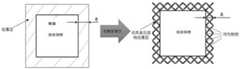
图4示出本发明实施例中的包覆层与待打印件的位置关系示意图;FIG. 4 shows a schematic diagram of the positional relationship between the cladding layer and the to-be-printed part in the embodiment of the present invention;
图5为本发明实施例中的待打印件、包覆层和预热的位置关系示意图。FIG. 5 is a schematic diagram of the positional relationship between the to-be-printed part, the coating layer and the preheating in an embodiment of the present invention.
具体实施方式Detailed ways
现在将参考附图更全面地描述示例实施方式。然而,示例实施方式能够以多种形式实施,且不应被理解为限于在此阐述的范例;相反,提供这些实施方式使得本公开将更加全面和完整,并将示例实施方式的构思全面地传达给本领域的技术人员。所描述的特征、结构或特性可以以任何合适的方式结合在一个或更多实施方式中。Example embodiments will now be described more fully with reference to the accompanying drawings. Example embodiments, however, can be embodied in various forms and should not be construed as limited to the examples set forth herein; rather, these embodiments are provided so that this disclosure will be thorough and complete, and will fully convey the concept of example embodiments to those skilled in the art. The described features, structures, or characteristics may be combined in any suitable manner in one or more embodiments.
请参考图1,本发明实施例首先提供了一种提升增材制造零件表面质量的方法,包括以下步骤:Referring to FIG. 1, an embodiment of the present invention first provides a method for improving the surface quality of an additively manufactured part, including the following steps:
步骤S101,建立待打印件的三维模型,在所述待打印件的三维模型的侧壁构建预设厚度的包覆层;Step S101, establishing a three-dimensional model of the to-be-printed part, and constructing a cladding layer with a preset thickness on the side wall of the three-dimensional model of the to-be-printed part;
步骤S102,将所述包覆层和所述三维模型进行切片得到分层扫描数据;Step S102, slicing the cladding layer and the three-dimensional model to obtain hierarchical scan data;
步骤S103,根据所述分层扫描数据规划扫描路径,对粉床进行预热和扫描熔化得到打印件实体。Step S103, planning a scanning path according to the layered scanning data, preheating the powder bed and scanning and melting to obtain a printed body.
本发明实施例中,通过在待打印件的侧壁设置包覆层,不仅可以作为待打印件侧壁的支撑,而且能够起到良好的热传导作用,将轮廓处的热量及时进行传导,避免轮廓处的热聚集造成的打印件变形,并且还能在气化扫描时固定打印件的外轮廓周围的粉床,防止气化导致的粉床上粉末的飞溅和吹粉。在不增加额外装置和多余后处理工序的前提下,有效去除零件外轮廓处粘连的多余粉末,从而在保证成形效率的基础上有效降低了成形零件的表面粗糙度,提升了成形零件的表面质量和尺寸精度,特别适用于一些高精密复杂零件的高精度成形。In the embodiment of the present invention, by setting the coating layer on the side wall of the to-be-printed part, it can not only serve as a support for the side wall of the to-be-printed part, but also can play a good heat conduction effect, conduct heat at the contour in time, and avoid the contour It can also fix the powder bed around the outer contour of the print during vaporization scanning, preventing the powder from splashing and blowing on the powder bed caused by vaporization. Under the premise of not adding additional devices and redundant post-processing procedures, the excess powder adhered to the outer contour of the part can be effectively removed, thereby effectively reducing the surface roughness of the formed part and improving the surface quality of the formed part on the basis of ensuring the forming efficiency. and dimensional accuracy, especially suitable for high-precision forming of some high-precision and complex parts.
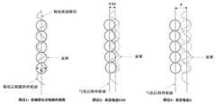
可选的,在一些实施例中,请参考图2,所述扫描路径包括:Optionally, in some embodiments, please refer to FIG. 2 , the scanning path includes:
第一扫描路径(路径1),对所述待打印件区域内的粉末进行扫描。其中,在一些实施例中,所述第一扫描路径可采用的电子束能量参数为:下束光斑离焦量为0.15~1.1V,例如,0.30V、0.50 V、0.80 V、1.0 V等等,下束功率为P1,束斑扫描速度为V1:2~8m/s,例如,可以为3 m/s、5 m/s等等,且2.6≤P1/V1≤30,例如,P1/V1这个比值可以为3.0、5.0、10、15、20、25等,但也不限于此。The first scanning path (path 1) scans the powder in the area of the to-be-printed part. Wherein, in some embodiments, the electron beam energy parameter that can be adopted by the first scanning path is: the defocus amount of the lower beam spot is 0.15~1.1V, for example, 0.30V, 0.50V, 0.80V, 1.0V, etc. , the lower beam power is P1, the beam spot scanning speed is V1: 2~8m/s, for example, it can be 3 m/s, 5 m/s, etc., and 2.6≤P1/V1≤30, for example, P1/V1 This ratio can be 3.0, 5.0, 10, 15, 20, 25, etc., but is not limited thereto.
第二扫描路径(路径2),对所述包覆层区域内的粉末进行扫描。其中,在一些实施例中,所述第二扫描路径可采用的电子束能量参数为:下束光斑离焦量为0~0.1V,例如0V、0.02V、0.05V等,下束功率为P2,束斑扫描速度为V2:0.5~1.2m/s,例如,可以为0.8 m/s、1.0m/s等,其中3.5≤P2/V2≤11,例如P2/V2这个比值可以为5、8、10等,但也不限于此。The second scanning path (path 2) scans the powder in the cladding layer area. Wherein, in some embodiments, the electron beam energy parameters that can be used in the second scanning path are: the defocus amount of the lower beam spot is 0~0.1V, such as 0V, 0.02V, 0.05V, etc., and the lower beam power is P2 , the beam spot scanning speed is V2: 0.5~1.2m/s, for example, it can be 0.8 m/s, 1.0m/s, etc., where 3.5≤P2/V2≤11, for example, the ratio of P2/V2 can be 5, 8 , 10, etc., but not limited to this.
第三扫描路径(路径3),对所述待打印件的轮廓线向里缩进第一预设距离进行气化扫描。其中,在一些实施例中,所述第三扫描路径可采用的电子束能量参数为:下束光斑离焦量为0~0.1V,例如0V、0.02V、0.05V等,下束功率为P3,扫描速度为V3:0.4~1.3m/s,例如,0.5 m/s、0.8 m/s、1.0 m/s等,15≤P3/V3≤45,例如P3/V3这个比值可以为18、20、25、30、40等。其中,可选的,请参考图3,所述第一预设距离为0.5~1d,例如可以为0.75d、0.80d等,d为扫描束斑的直径,但也不限于此。The third scanning path (path 3) is to perform vaporization scanning on the outline of the to-be-printed piece indented by a first preset distance. Wherein, in some embodiments, the electron beam energy parameters that can be used in the third scanning path are: the defocus amount of the lower beam spot is 0~0.1V, such as 0V, 0.02V, 0.05V, etc., and the lower beam power is P3 , the scanning speed is V3: 0.4~1.3m/s, for example, 0.5 m/s, 0.8 m/s, 1.0 m/s, etc., 15≤P3/V3≤45, for example, the ratio of P3/V3 can be 18, 20 , 25, 30, 40, etc. 3, the first preset distance is 0.5-1d, for example, 0.75d, 0.80d, etc., and d is the diameter of the scanning beam spot, but is not limited thereto.
可选的,在一些实施例中,实行以上三个扫描路径时,为保证零件成形和气化时固粉,路径1和路径2逐层扫描熔化。为达到气化效果且避免零件芯部反复重熔造成热量聚集引起内部组织粗大,路径3的气化扫描可以在每成形50~120μm高度后进行,但也不限于此,例如:切层厚度为30μm时,路径3每间隔3层(90μm)进行一次扫描熔化;切层厚度为50μm时,路径3每间隔2层(100μm)进行一次扫描熔化。例如,可选的,在一些实施例中,所述第三扫描路径的间隔预设层数为1~5层,例如可以为2层、3层、4层等。Optionally, in some embodiments, when the above three scanning paths are implemented, in order to ensure solid powder during forming and gasification of the part, path 1 and
此外,可选的,上述扫描路径可以是随机点扫描,也可以是S型往复扫描等,但也不限于此。In addition, optionally, the above-mentioned scanning path may be random point scanning, or S-shaped reciprocating scanning, etc., but is not limited thereto.
本发明实施例中,为保证成形效果,不同扫描路径下对应的电子束能量也不同,为兼顾零件表面质量和成形效率,路径1和路径2采用较低的能束进行快速熔化成形,路径3采用较高的能束进行精细熔化,达到气化效果。其中不同路径下的电子束能量通过控制电子束下束光斑的大小匹配不同的熔化工艺来实现。电子束下束光斑的大小通过下束光斑离焦量来控制,具体地:下束离焦量绝对值越大,则对应的电子束光斑越大,对应的束斑能量越低。不同光斑下的熔化工艺通过下束功率P和束斑扫描速度V来控制,具体地:P/V比值越大,对应的束斑能量越高。由此可以制造出表面质量较高的零件。In the embodiment of the present invention, in order to ensure the forming effect, the corresponding electron beam energies under different scanning paths are also different. In order to take into account the surface quality of the parts and the forming efficiency,
可选的,在一些实施例中,所述第三扫描路径每间隔预设层数进行。例如,将待打印零件的三维模型按一定的厚度t(30≤t≤50μm)进行切片分层,并对每层的数据进行路径规划:路径1和路径2进行逐层路径规划,路径3每间隔n层进行一次路径规划,其中n=[100/t]。合理设置路径3的气化扫描方案,可最大程度提升零件表面的成形质量。Optionally, in some embodiments, the third scanning path is performed at intervals of a preset number of layers. For example, the 3D model of the part to be printed is sliced and layered according to a certain thickness t (30≤t≤50μm), and the path planning is performed on the data of each layer: path 1 and
可选的,在一些实施例中,请参考图5,在利用所述第三扫描路径进行气化扫描之前,对所述包覆层区域向外延伸第二预设距离的粉床进行预热。其中,所述第二预设距离为2~12mm,例如,可以为4mm、6mm、8mm、10mm等等,但也不限于此。此处预热是对粉床进行的局部预热,采用局部预热而不是粉床整体预热是为了对气化周围热影响区的粉床进行预烧结固定,同时避免了粉床整体变硬造成的粉末回收困难。Optionally, in some embodiments, please refer to FIG. 5 , before using the third scanning path to perform gasification scanning, preheat the powder bed extending outward from the cladding layer region by a second preset distance. . Wherein, the second preset distance is 2˜12 mm, for example, may be 4 mm, 6 mm, 8 mm, 10 mm, etc., but is not limited thereto. The preheating here is the local preheating of the powder bed. The use of local preheating instead of the overall preheating of the powder bed is to pre-sinter and fix the powder bed in the heat affected zone around the gasification, while avoiding the overall hardening of the powder bed. Difficulty in powder recovery.
可选的,在一些实施例中,在利用所述第三扫描路径对待打印件进行气化扫描后,会将气化扫描前形成的包覆层进行去除。在零件加工结束的最后一层需进行一次气化扫描,以去除逐层熔化成形的包覆层,可在加工结束后直接获得高表面质量的零件。Optionally, in some embodiments, after vaporizing and scanning the to-be-printed piece by using the third scanning path, the coating layer formed before vaporizing and scanning is removed. At the end of the part processing, a gasification scan needs to be performed on the last layer to remove the layer-by-layer melt-formed cladding layer, and parts with high surface quality can be obtained directly after processing.
可选的,在一些实施例中,采用电子束、激光或离子束对粉床进行预热和扫描熔化得到打印件实体。本发明的方法适用于采用以上高能束能量源进行增材制造的扫描方法。Optionally, in some embodiments, an electron beam, a laser or an ion beam is used to preheat and scan the powder bed to obtain a printed object. The method of the present invention is suitable for a scanning method for additive manufacturing using the above high-energy beam energy source.
可选的,在一些实施例中,所述包覆层为多孔结构,例如可以为有序多孔结构,孔隙率可以为70~95%,例如80%、90%等。在一些实施例中,可以采用点阵多孔结构、桁架结构等,但也不限于此。Optionally, in some embodiments, the coating layer has a porous structure, such as an ordered porous structure, and the porosity can be 70-95%, such as 80%, 90%, and the like. In some embodiments, a lattice porous structure, a truss structure, etc. may be used, but not limited thereto.
可选的,在一些实施例中,请参考图4,所述包覆层的预设厚度δ为1~10mm,例如,可以为2 mm、4 mm、6 mm、8mm等等,但也不限于此。由于气化轮廓边缘的能量密度很高,气化时极易因严重的热量聚集造成零件从轮廓处发生变形;另外极大的电子束冲击能量还会引起粉床的严重飞溅,进而影响后续加工。这种镂空的多孔包覆层不仅可以作为零件侧壁的支撑进行均匀导热,此外还可起到固定粉床的作用,避免气化时引起严重飞溅影响后续铺粉和加工。该镂空多孔包覆层会在每层气化路径之后被直接气化切割掉,在加工结束后直接获得高表面质量的成形件。Optionally, in some embodiments, please refer to FIG. 4 , the preset thickness δ of the cladding layer is 1-10 mm, for example, it can be 2 mm, 4 mm, 6 mm, 8 mm, etc., but it is not limited to this. Due to the high energy density at the edge of the gasification contour, it is very easy for the parts to deform from the contour due to severe heat accumulation during gasification; in addition, the great electron beam impact energy will also cause serious splashing of the powder bed, which will affect subsequent processing. . The hollowed-out porous cladding layer can not only serve as a support for the side wall of the part to conduct uniform heat conduction, but also act as a fixed powder bed to avoid serious splashing during gasification and affect subsequent powder spreading and processing. The hollowed-out porous cladding layer will be directly gasified and cut off after each layer of gasification path, and a formed part with high surface quality will be obtained directly after processing.
下面以模型高度为70mm 的TC4(钛合金)零件为例进行说明:The following is an example of a TC4 (titanium alloy) part with a model height of 70mm:
步骤一:在待打印件模型轮廓外围生成厚度为2.5mm的点阵多孔结构包覆层,包覆层孔隙率为87.4%。将带有包覆层的三维模型按40μm层厚进行切层,共1750层。然后对切层数据进行路径规划:路径1和路径2进行逐层规划,路径3每间隔n=[100/40]=2层进行一次路径规划,即:Step 1: A lattice porous structure cladding layer with a thickness of 2.5mm is generated around the outline of the model to be printed, and the porosity of the cladding layer is 87.4%. The three-dimensional model with the cladding layer was sliced with a layer thickness of 40 μm, with a total of 1750 layers. Then perform path planning for sliced data: path 1 and
第一层:规划路径1和路径2;The first layer: planning path 1 and
第二层:规划路径1、路径2和路径3;The second layer: planning path 1,
第三层:规划路径1和路径2;The third layer: planning path 1 and
第四层:规划路径1、路径2和路径3;The fourth layer: planning path 1,
……...
第1750层:规划路径1、路径2和路径3。Layer 1750: Plan Path 1,
步骤二:将步骤一获得的离散分层扫描数据导入电子束扫描控制软件中,在预先加热至800℃的底板上均匀铺设一层40μm的TC4粉末,并对粉床进行整体均匀预热。Step 2: Import the discrete layered scanning data obtained in Step 1 into the electron beam scanning control software, and evenly lay a layer of 40 μm TC4 powder on the bottom plate preheated to 800°C, and preheat the powder bed uniformly as a whole.
设置路径1的下束离焦量为0.5V,下束功率17mA,束斑扫描速度5.2m/s;路径2的下束离焦量为0V,下束功率2.8mA,束斑扫描速度0.6m/s;路径3的下束离焦量为0V,下束功率13.6mA,束斑扫描速度0.8m/s。The lower beam defocus amount of path 1 is set to 0.5V, the lower beam power is 17mA, and the beam spot scanning speed is 5.2m/s; the lower beam defocus amount of
步骤三:第1层加工,扫描熔化路径1和路径2。Step 3: Process the first layer, scan the melting path 1 and
步骤四:铺粉,进行粉床整体预热。Step 4: Spread the powder and preheat the powder bed as a whole.
步骤五:第2层加工,扫描熔化路径1和路径2,然后在包覆层外围5mm范围内进行粉床局部预热,之后再扫描熔化路径3。气化路径3之后,会直接切割掉第一层和第二层加工成形的包覆层。Step 5: Process the second layer, scan the melting path 1 and
步骤六:第3层加工,扫描熔化路径1和路径2。Step 6: Process the third layer, scan the melting path 1 and
……...
重复以上步骤,直至完成零件加工。Repeat the above steps until the part is processed.
其中,可以在零件加工成形前的最后一层利用路径3进行一次气化扫描。Among them, the path 3 can be used to perform a vaporization scan in the last layer before the part is processed and formed.
本发明实施例还提供了一种增材制造设备,对待打印件采用以下方法进行增材制造:The embodiment of the present invention also provides an additive manufacturing device, which uses the following method for additive manufacturing of the to-be-printed part:
建立待打印件的三维模型,在所述待打印件的三维模型的侧壁构建预设厚度的包覆层;establishing a three-dimensional model of the to-be-printed part, and constructing a cladding layer with a preset thickness on the sidewall of the three-dimensional model of the to-be-printed part;
将所述包覆层和所述三维模型进行切片得到分层扫描数据;Slicing the cladding layer and the three-dimensional model to obtain layered scan data;
根据所述分层扫描数据规划扫描路径,对粉床进行预热和扫描熔化得到打印件实体;Planning a scanning path according to the layered scanning data, preheating the powder bed and scanning and melting to obtain a print entity;
其中,所述方法为上述任一个实施例所述的提升增材制造零件表面质量的方法。Wherein, the method is the method for improving the surface quality of an additively manufactured part described in any one of the above embodiments.
采用该方法进行增材制造得到的零件,在零件加工结束可直接获得高表面质量的零件,整个过程中无需增加额外的装置,且省去了传统的喷砂、打磨等零件后处理步骤,操作简单、成本低;本发明通过零件轮廓外围的包覆层设计和粉床局部预热设置,可避免气化时零件轮廓变形和粉床飞溅吹粉,可保证气化过程顺利进行,在加工结束直接获得高表面质量的零件;适合高精密复杂零件的打印成形。For the parts obtained by additive manufacturing using this method, parts with high surface quality can be directly obtained at the end of the part processing. There is no need to add additional devices in the whole process, and traditional post-processing steps such as sandblasting and grinding are omitted. Simple and low cost; the invention can avoid the deformation of the part contour and the powder bed splashing and blowing during gasification through the design of the coating layer on the periphery of the part contour and the local preheating setting of the powder bed, and can ensure the smooth progress of the gasification process. Directly obtain parts with high surface quality; suitable for printing and forming of high-precision and complex parts.
需要理解的是,上述描述中的术语“中心”、“纵向”、“横向”、“长度”、“宽度”、“厚度”、“上”、“下”、“前”、“后”、“左”、“右”、“竖直”、“水平”、“顶”、“底” “内”、“外”、“顺时针”、“逆时针”等指示的方位或位置关系为基于附图所示的方位或位置关系,仅是为了便于描述本发明实施例和简化描述,而不是指示或暗示所指的装置或元件必须具有特定的方位、以特定的方位构造和操作,因此不能理解为对本发明实施例的限制。It should be understood that the terms "center", "longitudinal", "lateral", "length", "width", "thickness", "upper", "lower", "front", "rear", The orientation or positional relationship indicated by "left", "right", "vertical", "horizontal", "top", "bottom", "inside", "outside", "clockwise", "counterclockwise", etc. is based on The orientation or positional relationship shown in the accompanying drawings is only for the convenience of describing the embodiments of the present invention and simplifying the description, rather than indicating or implying that the referred device or element must have a specific orientation, be constructed and operated in a specific orientation, and therefore cannot It is understood as a limitation on the embodiments of the present invention.
此外,术语“第一”、“第二”仅用于描述目的,而不能理解为指示或暗示相对重要性或者隐含指明所指示的技术特征的数量。由此,限定有“第一”、“第二”的特征可以明示或者隐含地包括一个或者更多个该特征。在本发明实施例的描述中,“多个”的含义是两个或两个以上,除非另有明确具体的限定。In addition, the terms "first" and "second" are only used for descriptive purposes, and should not be construed as indicating or implying relative importance or implying the number of indicated technical features. Thus, a feature defined as "first" or "second" may expressly or implicitly include one or more of that feature. In the description of the embodiments of the present invention, "plurality" means two or more, unless otherwise expressly and specifically defined.
在本发明实施例中,除非另有明确的规定和限定,术语“安装”、“相连”、“连接”、“固定”等术语应做广义理解,例如,可以是固定连接,也可以是可拆卸连接,或成一体;可以是机械连接,也可以是电连接;可以是直接相连,也可以通过中间媒介间接相连,可以是两个元件内部的连通或两个元件的相互作用关系。对于本领域的普通技术人员而言,可以根据具体情况理解上述术语在本公开中的具体含义。In the embodiments of the present invention, unless otherwise expressly specified and limited, terms such as “installation”, “connection”, “connection”, and “fixation” should be understood in a broad sense. For example, it may be a fixed connection or a It can be a mechanical connection or an electrical connection; it can be a direct connection or an indirect connection through an intermediate medium, and it can be the internal communication of the two elements or the interaction relationship between the two elements. For those of ordinary skill in the art, the specific meanings of the above terms in the present disclosure can be understood according to specific situations.
在本发明实施例中,除非另有明确的规定和限定,第一特征在第二特征之“上”或之“下”可以包括第一和第二特征直接接触,也可以包括第一和第二特征不是直接接触而是通过它们之间的另外的特征接触。而且,第一特征在第二特征“之上”、“上方”和“上面”包括第一特征在第二特征正上方和斜上方,或仅仅表示第一特征水平高度高于第二特征。第一特征在第二特征“之下”、“下方”和“下面”包括第一特征在第二特征正下方和斜下方,或仅仅表示第一特征水平高度小于第二特征。In the embodiments of the present invention, unless otherwise expressly specified and limited, the first feature "on" or "under" the second feature may include the first and second features in direct contact, or may include the first and second features The two features are not in direct contact but through another feature between them. Also, the first feature being "above", "over" and "above" the second feature includes the first feature being directly above and obliquely above the second feature, or simply means that the first feature is level higher than the second feature. The first feature is "below", "below" and "below" the second feature includes the first feature being directly below and diagonally below the second feature, or simply means that the first feature has a lower level than the second feature.
在本说明书的描述中,参考术语“一个实施例”、“一些实施例”、“示例”、“具体示例”、或“一些示例”等的描述意指结合该实施例或示例描述的具体特征、结构、材料或者特点包含于本公开的至少一个实施例或示例中。在本说明书中,对上述术语的示意性表述不必须针对的是相同的实施例或示例。而且,描述的具体特征、结构、材料或者特点可以在任何的一个或多个实施例或示例中以合适的方式结合。此外,本领域的技术人员可以将本说明书中描述的不同实施例或示例进行结合和组合。In the description of this specification, description with reference to the terms "one embodiment," "some embodiments," "example," "specific example," or "some examples", etc., mean specific features described in connection with the embodiment or example , structures, materials, or features are included in at least one embodiment or example of the present disclosure. In this specification, schematic representations of the above terms are not necessarily directed to the same embodiment or example. Furthermore, the particular features, structures, materials or characteristics described may be combined in any suitable manner in any one or more embodiments or examples. Furthermore, those skilled in the art may combine and combine the different embodiments or examples described in this specification.
本领域技术人员在考虑说明书及实践这里公开的发明后,将容易想到本公开的其它实施方案。本申请旨在涵盖本公开的任何变型、用途或者适应性变化,这些变型、用途或者适应性变化遵循本公开的一般性原理并包括本公开未公开的本技术领域中的公知常识或惯用技术手段。说明书和实施例仅被视为示例性的,本公开的真正范围和精神由所附的权利要求指出。Other embodiments of the present disclosure will readily occur to those skilled in the art upon consideration of the specification and practice of the invention disclosed herein. This application is intended to cover any variations, uses, or adaptations of the present disclosure that follow the general principles of the present disclosure and include common knowledge or techniques in the technical field not disclosed by the present disclosure . The specification and examples are to be regarded as exemplary only, with the true scope and spirit of the disclosure being indicated by the appended claims.
Claims (6)
Priority Applications (2)
| Application Number | Priority Date | Filing Date | Title |
|---|---|---|---|
| CN202210653266.0ACN114713848B (en) | 2022-06-10 | 2022-06-10 | Method for improving surface quality of additive manufacturing part and additive manufacturing equipment |
| PCT/CN2022/121973WO2023236394A1 (en) | 2022-06-10 | 2022-09-28 | Method for improving surface quality of additive manufacturing part and additive manufacturing device |
Applications Claiming Priority (1)
| Application Number | Priority Date | Filing Date | Title |
|---|---|---|---|
| CN202210653266.0ACN114713848B (en) | 2022-06-10 | 2022-06-10 | Method for improving surface quality of additive manufacturing part and additive manufacturing equipment |
Publications (2)
| Publication Number | Publication Date |
|---|---|
| CN114713848A CN114713848A (en) | 2022-07-08 |
| CN114713848Btrue CN114713848B (en) | 2022-09-23 |
Family
ID=82232906
Family Applications (1)
| Application Number | Title | Priority Date | Filing Date |
|---|---|---|---|
| CN202210653266.0AActiveCN114713848B (en) | 2022-06-10 | 2022-06-10 | Method for improving surface quality of additive manufacturing part and additive manufacturing equipment |
Country Status (2)
| Country | Link |
|---|---|
| CN (1) | CN114713848B (en) |
| WO (1) | WO2023236394A1 (en) |
Families Citing this family (11)
| Publication number | Priority date | Publication date | Assignee | Title |
|---|---|---|---|---|
| CN114713848B (en)* | 2022-06-10 | 2022-09-23 | 西安赛隆增材技术股份有限公司 | Method for improving surface quality of additive manufacturing part and additive manufacturing equipment |
| CN115815627B (en)* | 2022-11-16 | 2025-03-07 | 鑫精合激光科技发展(北京)有限公司 | A method and device for forming an opening structure part |
| CN116689785B (en)* | 2023-08-08 | 2023-10-17 | 西安赛隆增材技术股份有限公司 | An additive manufacturing method to solve the warping deformation of suspended surface structures |
| CN117483799B (en)* | 2023-12-29 | 2024-04-02 | 西安赛隆增材技术股份有限公司 | A powder bed electron beam additive manufacturing method of aluminum alloy |
| CN117961090A (en)* | 2024-04-02 | 2024-05-03 | 四川工程职业技术大学 | Material adding manufacturing method of aircraft valve |
| CN118321573B (en)* | 2024-06-13 | 2024-08-30 | 西安赛隆增材技术股份有限公司 | Additive manufacturing method for TiAl alloy blade |
| CN118635529B (en)* | 2024-08-15 | 2024-11-05 | 西安赛隆增材技术股份有限公司 | Three-dimensional manufacturing method |
| CN119885302B (en)* | 2024-11-18 | 2025-10-03 | 中南大学 | High-throughput evaluation and optimization method for formability of additively manufactured suspended structures |
| CN119319261B (en)* | 2024-12-17 | 2025-04-25 | 西安赛隆增材技术股份有限公司 | An additive manufacturing method for zirconium-niobium alloy orthopedic implants |
| CN119794382B (en)* | 2025-03-14 | 2025-07-11 | 安世数擎(杭州)信息科技服务有限公司 | Polymorphic progressive three-dimensional forming method |
| CN120480223B (en)* | 2025-07-17 | 2025-09-30 | 西安赛隆增材技术股份有限公司 | A method for determining scanning melting energy in additive manufacturing |
Citations (12)
| Publication number | Priority date | Publication date | Assignee | Title |
|---|---|---|---|---|
| CN106825567A (en)* | 2017-01-22 | 2017-06-13 | 清华大学 | The electron beam selective melting increasing material manufacturing equipment compound with electron beam cutting |
| CN107498053A (en)* | 2017-09-30 | 2017-12-22 | 华中科技大学 | It is a kind of to eliminate the method that edge heap is high in laser gain material manufacture shaping |
| CN108907196A (en)* | 2018-09-03 | 2018-11-30 | 江苏典悦三维科技有限公司 | Laser increases and decreases material composite manufacturing device and method |
| CN109047762A (en)* | 2018-08-31 | 2018-12-21 | 江苏大学 | A kind of increasing material manufacturing method that selective laser fusing is compound with laser cutting |
| KR20190041133A (en)* | 2017-10-12 | 2019-04-22 | 한국기계연구원 | Method for manufacturing three dimensional shapes using laser and powder |
| CN110052713A (en)* | 2019-03-22 | 2019-07-26 | 江南大学 | Part increases and decreases material composite manufacturing technology |
| CN110369725A (en)* | 2019-08-02 | 2019-10-25 | 上海工程技术大学 | Near-net-shape method and device based on laser increase and decrease material composite manufacturing delicate workpieces |
| WO2020058722A1 (en)* | 2018-09-20 | 2020-03-26 | Camadd Ltd | A powder bed: additive manufacturing |
| CN111151744A (en)* | 2019-12-03 | 2020-05-15 | 汕头大学 | A kind of cutting and cutting integrated additive equipment and method based on EBM and femtosecond laser |
| CN111992877A (en)* | 2020-07-07 | 2020-11-27 | 上海工程技术大学 | A composite manufacturing device for high-precision laser addition and subtraction of materials |
| CN214443088U (en)* | 2020-10-30 | 2021-10-22 | 广东工业大学 | A laser adding and subtracting material composite five-axis machining forming equipment |
| CN114425625A (en)* | 2022-01-14 | 2022-05-03 | 中国人民解放军军事科学院国防科技创新研究院 | Pulsed laser additive and subtractive manufacturing system and method |
Family Cites Families (9)
| Publication number | Priority date | Publication date | Assignee | Title |
|---|---|---|---|---|
| SG106041A1 (en)* | 2000-03-21 | 2004-09-30 | Nanyang Polytechnic | Plastic components with improved surface appearance and method of making the same |
| JP4452692B2 (en)* | 2006-02-03 | 2010-04-21 | 株式会社松浦機械製作所 | Surface finishing method for 3D additive manufacturing parts |
| DE102009051479A1 (en)* | 2009-10-30 | 2011-05-05 | Mtu Aero Engines Gmbh | Method and device for producing a component of a turbomachine |
| CN105538728A (en)* | 2016-02-23 | 2016-05-04 | 中国科学院重庆绿色智能技术研究院 | Laser material increasing and decreasing combined manufacturing method and device |
| CN108248011B (en)* | 2017-12-20 | 2019-08-27 | 广东工业大学 | A laser impact forging and laser cutting composite additive manufacturing device and method |
| CN108380877B (en)* | 2018-03-24 | 2019-07-09 | 安徽拓宝增材制造科技有限公司 | A kind of laser sintering method of metal powder |
| CN109571017A (en)* | 2018-11-30 | 2019-04-05 | 宁波匠心快速成型技术有限公司 | A kind of high-precision increase and decrease material 3D printing method and device |
| CN112496345B (en)* | 2021-02-05 | 2021-05-14 | 西安赛隆金属材料有限责任公司 | Cemented carbide additive preparation method |
| CN114713848B (en)* | 2022-06-10 | 2022-09-23 | 西安赛隆增材技术股份有限公司 | Method for improving surface quality of additive manufacturing part and additive manufacturing equipment |
- 2022
- 2022-06-10CNCN202210653266.0Apatent/CN114713848B/enactiveActive
- 2022-09-28WOPCT/CN2022/121973patent/WO2023236394A1/ennot_activeCeased
Patent Citations (12)
| Publication number | Priority date | Publication date | Assignee | Title |
|---|---|---|---|---|
| CN106825567A (en)* | 2017-01-22 | 2017-06-13 | 清华大学 | The electron beam selective melting increasing material manufacturing equipment compound with electron beam cutting |
| CN107498053A (en)* | 2017-09-30 | 2017-12-22 | 华中科技大学 | It is a kind of to eliminate the method that edge heap is high in laser gain material manufacture shaping |
| KR20190041133A (en)* | 2017-10-12 | 2019-04-22 | 한국기계연구원 | Method for manufacturing three dimensional shapes using laser and powder |
| CN109047762A (en)* | 2018-08-31 | 2018-12-21 | 江苏大学 | A kind of increasing material manufacturing method that selective laser fusing is compound with laser cutting |
| CN108907196A (en)* | 2018-09-03 | 2018-11-30 | 江苏典悦三维科技有限公司 | Laser increases and decreases material composite manufacturing device and method |
| WO2020058722A1 (en)* | 2018-09-20 | 2020-03-26 | Camadd Ltd | A powder bed: additive manufacturing |
| CN110052713A (en)* | 2019-03-22 | 2019-07-26 | 江南大学 | Part increases and decreases material composite manufacturing technology |
| CN110369725A (en)* | 2019-08-02 | 2019-10-25 | 上海工程技术大学 | Near-net-shape method and device based on laser increase and decrease material composite manufacturing delicate workpieces |
| CN111151744A (en)* | 2019-12-03 | 2020-05-15 | 汕头大学 | A kind of cutting and cutting integrated additive equipment and method based on EBM and femtosecond laser |
| CN111992877A (en)* | 2020-07-07 | 2020-11-27 | 上海工程技术大学 | A composite manufacturing device for high-precision laser addition and subtraction of materials |
| CN214443088U (en)* | 2020-10-30 | 2021-10-22 | 广东工业大学 | A laser adding and subtracting material composite five-axis machining forming equipment |
| CN114425625A (en)* | 2022-01-14 | 2022-05-03 | 中国人民解放军军事科学院国防科技创新研究院 | Pulsed laser additive and subtractive manufacturing system and method |
Also Published As
| Publication number | Publication date |
|---|---|
| CN114713848A (en) | 2022-07-08 |
| WO2023236394A1 (en) | 2023-12-14 |
Similar Documents
| Publication | Publication Date | Title |
|---|---|---|
| CN114713848B (en) | Method for improving surface quality of additive manufacturing part and additive manufacturing equipment | |
| CN105903961B (en) | A kind of scanning moulding method for improving metal parts increasing material manufacturing Forming Quality | |
| CN106808681B (en) | A method to improve the accuracy of additively manufactured parts | |
| WO2022100396A1 (en) | Formed part having inclined surface and forming method therefor | |
| WO2019091086A1 (en) | Metal fine porous structure forming method based on selective laser melting | |
| US11565349B2 (en) | Composite device for high-precision laser additive/subtractive manufacturing | |
| CN115106545A (en) | Coaxial coupling multi-laser material increasing and decreasing composite forming device and method | |
| WO2022100397A1 (en) | Forming part having cantilever structure and forming method therefor | |
| CN112496345B (en) | Cemented carbide additive preparation method | |
| CN105983786B (en) | A method of glass processing is realized using laser | |
| CN113976914B (en) | Laser selective melting forming process based on control surface bionic structure | |
| CN111036905A (en) | Method for improving density and avoiding hole defects by using layer-by-layer repeated laser remelting | |
| CN101899662A (en) | Methods of Improving the Surface Flatness of Laser Metal Forming Parts | |
| CN117182106A (en) | Method for manufacturing unsupported laser selective melting additive | |
| CN105537590A (en) | Method for reducing hot stack influences of metal SLM three-dimensional printing | |
| JP2002066844A (en) | Method of manufacturing discharge machining electrode using metal powder sintering type laminated molding | |
| CN111136355B (en) | Electrolytic machining method for laminated disc-shaped electrolytic machining tool electrode | |
| CN105081320A (en) | 3d printing device | |
| CN116689785B (en) | An additive manufacturing method to solve the warping deformation of suspended surface structures | |
| CN111687414A (en) | Multi-beam electron beam forming method | |
| CN116604044A (en) | Stirring rolling device and method for improving additive manufacturing quality | |
| CN204912763U (en) | 3d printing device | |
| CN116237539A (en) | 3D printing method for uniform micron-sized directional porous metal material | |
| JP6229411B2 (en) | Laser processing apparatus and laser processing method | |
| CN107511481A (en) | A kind of 3D printing of overlength metalwork, heat treatment integral processing method |
Legal Events
| Date | Code | Title | Description |
|---|---|---|---|
| PB01 | Publication | ||
| PB01 | Publication | ||
| SE01 | Entry into force of request for substantive examination | ||
| SE01 | Entry into force of request for substantive examination | ||
| CB02 | Change of applicant information | Address after:Room 303-46, building a, Kairui, Fengcheng 12th Road, Xi'an Economic and Technological Development Zone, Shaanxi 710018 Applicant after:Xi'an Sailong Additive Technology Co.,Ltd. Address before:Room 303-46, building a, Kairui, Fengcheng 12th Road, Xi'an Economic and Technological Development Zone, Shaanxi 710018 Applicant before:XI'AN SAILONG METAL MATERIALS Co.,Ltd. | |
| CB02 | Change of applicant information | ||
| GR01 | Patent grant | ||
| GR01 | Patent grant | ||
| CP03 | Change of name, title or address | Address after:No. 666 Zaohe East Road, High speed Railway New City, Xi'an Economic and Technological Development Zone, Shaanxi Province, 710018 Patentee after:Xi'an Sailong Additive Technology Co.,Ltd. Country or region after:China Address before:Room 303-46, building a, Kairui, Fengcheng 12th Road, Xi'an Economic and Technological Development Zone, Shaanxi 710018 Patentee before:Xi'an Sailong Additive Technology Co.,Ltd. Country or region before:China | |
| CP03 | Change of name, title or address |