CN114712615A - System and device for sustained delivery of therapeutic fluid - Google Patents
System and device for sustained delivery of therapeutic fluidDownload PDFInfo
- Publication number
- CN114712615A CN114712615ACN202210376348.5ACN202210376348ACN114712615ACN 114712615 ACN114712615 ACN 114712615ACN 202210376348 ACN202210376348 ACN 202210376348ACN 114712615 ACN114712615 ACN 114712615A
- Authority
- CN
- China
- Prior art keywords
- unit
- cannula
- stent
- component
- well
- Prior art date
- Legal status (The legal status is an assumption and is not a legal conclusion. Google has not performed a legal analysis and makes no representation as to the accuracy of the status listed.)
- Granted
Links
Images


Classifications
- A—HUMAN NECESSITIES
- A61—MEDICAL OR VETERINARY SCIENCE; HYGIENE
- A61M—DEVICES FOR INTRODUCING MEDIA INTO, OR ONTO, THE BODY; DEVICES FOR TRANSDUCING BODY MEDIA OR FOR TAKING MEDIA FROM THE BODY; DEVICES FOR PRODUCING OR ENDING SLEEP OR STUPOR
- A61M5/00—Devices for bringing media into the body in a subcutaneous, intra-vascular or intramuscular way; Accessories therefor, e.g. filling or cleaning devices, arm-rests
- A61M5/14—Infusion devices, e.g. infusing by gravity; Blood infusion; Accessories therefor
- A61M5/142—Pressure infusion, e.g. using pumps
- A61M5/14244—Pressure infusion, e.g. using pumps adapted to be carried by the patient, e.g. portable on the body
- A61M5/14248—Pressure infusion, e.g. using pumps adapted to be carried by the patient, e.g. portable on the body of the skin patch type
- A—HUMAN NECESSITIES
- A61—MEDICAL OR VETERINARY SCIENCE; HYGIENE
- A61M—DEVICES FOR INTRODUCING MEDIA INTO, OR ONTO, THE BODY; DEVICES FOR TRANSDUCING BODY MEDIA OR FOR TAKING MEDIA FROM THE BODY; DEVICES FOR PRODUCING OR ENDING SLEEP OR STUPOR
- A61M39/00—Tubes, tube connectors, tube couplings, valves, access sites or the like, specially adapted for medical use
- A61M39/02—Access sites
- A61M39/04—Access sites having pierceable self-sealing members
- A—HUMAN NECESSITIES
- A61—MEDICAL OR VETERINARY SCIENCE; HYGIENE
- A61M—DEVICES FOR INTRODUCING MEDIA INTO, OR ONTO, THE BODY; DEVICES FOR TRANSDUCING BODY MEDIA OR FOR TAKING MEDIA FROM THE BODY; DEVICES FOR PRODUCING OR ENDING SLEEP OR STUPOR
- A61M5/00—Devices for bringing media into the body in a subcutaneous, intra-vascular or intramuscular way; Accessories therefor, e.g. filling or cleaning devices, arm-rests
- A61M5/14—Infusion devices, e.g. infusing by gravity; Blood infusion; Accessories therefor
- A61M5/142—Pressure infusion, e.g. using pumps
- A61M5/14212—Pumping with an aspiration and an expulsion action
- A61M5/14224—Diaphragm type
- A—HUMAN NECESSITIES
- A61—MEDICAL OR VETERINARY SCIENCE; HYGIENE
- A61M—DEVICES FOR INTRODUCING MEDIA INTO, OR ONTO, THE BODY; DEVICES FOR TRANSDUCING BODY MEDIA OR FOR TAKING MEDIA FROM THE BODY; DEVICES FOR PRODUCING OR ENDING SLEEP OR STUPOR
- A61M5/00—Devices for bringing media into the body in a subcutaneous, intra-vascular or intramuscular way; Accessories therefor, e.g. filling or cleaning devices, arm-rests
- A61M5/14—Infusion devices, e.g. infusing by gravity; Blood infusion; Accessories therefor
- A61M5/142—Pressure infusion, e.g. using pumps
- A61M5/14212—Pumping with an aspiration and an expulsion action
- A61M5/14232—Roller pumps
- A—HUMAN NECESSITIES
- A61—MEDICAL OR VETERINARY SCIENCE; HYGIENE
- A61M—DEVICES FOR INTRODUCING MEDIA INTO, OR ONTO, THE BODY; DEVICES FOR TRANSDUCING BODY MEDIA OR FOR TAKING MEDIA FROM THE BODY; DEVICES FOR PRODUCING OR ENDING SLEEP OR STUPOR
- A61M5/00—Devices for bringing media into the body in a subcutaneous, intra-vascular or intramuscular way; Accessories therefor, e.g. filling or cleaning devices, arm-rests
- A61M5/14—Infusion devices, e.g. infusing by gravity; Blood infusion; Accessories therefor
- A61M5/142—Pressure infusion, e.g. using pumps
- A61M5/14212—Pumping with an aspiration and an expulsion action
- A61M5/1424—Manually operated pumps
- A—HUMAN NECESSITIES
- A61—MEDICAL OR VETERINARY SCIENCE; HYGIENE
- A61M—DEVICES FOR INTRODUCING MEDIA INTO, OR ONTO, THE BODY; DEVICES FOR TRANSDUCING BODY MEDIA OR FOR TAKING MEDIA FROM THE BODY; DEVICES FOR PRODUCING OR ENDING SLEEP OR STUPOR
- A61M5/00—Devices for bringing media into the body in a subcutaneous, intra-vascular or intramuscular way; Accessories therefor, e.g. filling or cleaning devices, arm-rests
- A61M5/14—Infusion devices, e.g. infusing by gravity; Blood infusion; Accessories therefor
- A61M5/158—Needles for infusions; Accessories therefor, e.g. for inserting infusion needles, or for holding them on the body
- A—HUMAN NECESSITIES
- A61—MEDICAL OR VETERINARY SCIENCE; HYGIENE
- A61M—DEVICES FOR INTRODUCING MEDIA INTO, OR ONTO, THE BODY; DEVICES FOR TRANSDUCING BODY MEDIA OR FOR TAKING MEDIA FROM THE BODY; DEVICES FOR PRODUCING OR ENDING SLEEP OR STUPOR
- A61M5/00—Devices for bringing media into the body in a subcutaneous, intra-vascular or intramuscular way; Accessories therefor, e.g. filling or cleaning devices, arm-rests
- A61M5/14—Infusion devices, e.g. infusing by gravity; Blood infusion; Accessories therefor
- A61M5/168—Means for controlling media flow to the body or for metering media to the body, e.g. drip meters, counters ; Monitoring media flow to the body
- A61M5/16831—Monitoring, detecting, signalling or eliminating infusion flow anomalies
- A—HUMAN NECESSITIES
- A61—MEDICAL OR VETERINARY SCIENCE; HYGIENE
- A61M—DEVICES FOR INTRODUCING MEDIA INTO, OR ONTO, THE BODY; DEVICES FOR TRANSDUCING BODY MEDIA OR FOR TAKING MEDIA FROM THE BODY; DEVICES FOR PRODUCING OR ENDING SLEEP OR STUPOR
- A61M5/00—Devices for bringing media into the body in a subcutaneous, intra-vascular or intramuscular way; Accessories therefor, e.g. filling or cleaning devices, arm-rests
- A61M5/14—Infusion devices, e.g. infusing by gravity; Blood infusion; Accessories therefor
- A61M5/168—Means for controlling media flow to the body or for metering media to the body, e.g. drip meters, counters ; Monitoring media flow to the body
- A61M5/172—Means for controlling media flow to the body or for metering media to the body, e.g. drip meters, counters ; Monitoring media flow to the body electrical or electronic
- A—HUMAN NECESSITIES
- A61—MEDICAL OR VETERINARY SCIENCE; HYGIENE
- A61M—DEVICES FOR INTRODUCING MEDIA INTO, OR ONTO, THE BODY; DEVICES FOR TRANSDUCING BODY MEDIA OR FOR TAKING MEDIA FROM THE BODY; DEVICES FOR PRODUCING OR ENDING SLEEP OR STUPOR
- A61M5/00—Devices for bringing media into the body in a subcutaneous, intra-vascular or intramuscular way; Accessories therefor, e.g. filling or cleaning devices, arm-rests
- A61M5/14—Infusion devices, e.g. infusing by gravity; Blood infusion; Accessories therefor
- A61M5/142—Pressure infusion, e.g. using pumps
- A61M5/14244—Pressure infusion, e.g. using pumps adapted to be carried by the patient, e.g. portable on the body
- A61M5/14248—Pressure infusion, e.g. using pumps adapted to be carried by the patient, e.g. portable on the body of the skin patch type
- A61M2005/14252—Pressure infusion, e.g. using pumps adapted to be carried by the patient, e.g. portable on the body of the skin patch type with needle insertion means
- A—HUMAN NECESSITIES
- A61—MEDICAL OR VETERINARY SCIENCE; HYGIENE
- A61M—DEVICES FOR INTRODUCING MEDIA INTO, OR ONTO, THE BODY; DEVICES FOR TRANSDUCING BODY MEDIA OR FOR TAKING MEDIA FROM THE BODY; DEVICES FOR PRODUCING OR ENDING SLEEP OR STUPOR
- A61M5/00—Devices for bringing media into the body in a subcutaneous, intra-vascular or intramuscular way; Accessories therefor, e.g. filling or cleaning devices, arm-rests
- A61M5/14—Infusion devices, e.g. infusing by gravity; Blood infusion; Accessories therefor
- A61M5/142—Pressure infusion, e.g. using pumps
- A61M5/14244—Pressure infusion, e.g. using pumps adapted to be carried by the patient, e.g. portable on the body
- A61M2005/14268—Pressure infusion, e.g. using pumps adapted to be carried by the patient, e.g. portable on the body with a reusable and a disposable component
- A—HUMAN NECESSITIES
- A61—MEDICAL OR VETERINARY SCIENCE; HYGIENE
- A61M—DEVICES FOR INTRODUCING MEDIA INTO, OR ONTO, THE BODY; DEVICES FOR TRANSDUCING BODY MEDIA OR FOR TAKING MEDIA FROM THE BODY; DEVICES FOR PRODUCING OR ENDING SLEEP OR STUPOR
- A61M5/00—Devices for bringing media into the body in a subcutaneous, intra-vascular or intramuscular way; Accessories therefor, e.g. filling or cleaning devices, arm-rests
- A61M5/14—Infusion devices, e.g. infusing by gravity; Blood infusion; Accessories therefor
- A61M5/158—Needles for infusions; Accessories therefor, e.g. for inserting infusion needles, or for holding them on the body
- A61M2005/1581—Right-angle needle-type devices
- A—HUMAN NECESSITIES
- A61—MEDICAL OR VETERINARY SCIENCE; HYGIENE
- A61M—DEVICES FOR INTRODUCING MEDIA INTO, OR ONTO, THE BODY; DEVICES FOR TRANSDUCING BODY MEDIA OR FOR TAKING MEDIA FROM THE BODY; DEVICES FOR PRODUCING OR ENDING SLEEP OR STUPOR
- A61M5/00—Devices for bringing media into the body in a subcutaneous, intra-vascular or intramuscular way; Accessories therefor, e.g. filling or cleaning devices, arm-rests
- A61M5/14—Infusion devices, e.g. infusing by gravity; Blood infusion; Accessories therefor
- A61M5/158—Needles for infusions; Accessories therefor, e.g. for inserting infusion needles, or for holding them on the body
- A61M2005/1585—Needle inserters
- A—HUMAN NECESSITIES
- A61—MEDICAL OR VETERINARY SCIENCE; HYGIENE
- A61M—DEVICES FOR INTRODUCING MEDIA INTO, OR ONTO, THE BODY; DEVICES FOR TRANSDUCING BODY MEDIA OR FOR TAKING MEDIA FROM THE BODY; DEVICES FOR PRODUCING OR ENDING SLEEP OR STUPOR
- A61M5/00—Devices for bringing media into the body in a subcutaneous, intra-vascular or intramuscular way; Accessories therefor, e.g. filling or cleaning devices, arm-rests
- A61M5/14—Infusion devices, e.g. infusing by gravity; Blood infusion; Accessories therefor
- A61M5/168—Means for controlling media flow to the body or for metering media to the body, e.g. drip meters, counters ; Monitoring media flow to the body
- A61M5/16831—Monitoring, detecting, signalling or eliminating infusion flow anomalies
- A61M2005/16863—Occlusion detection
- A—HUMAN NECESSITIES
- A61—MEDICAL OR VETERINARY SCIENCE; HYGIENE
- A61M—DEVICES FOR INTRODUCING MEDIA INTO, OR ONTO, THE BODY; DEVICES FOR TRANSDUCING BODY MEDIA OR FOR TAKING MEDIA FROM THE BODY; DEVICES FOR PRODUCING OR ENDING SLEEP OR STUPOR
- A61M2205/00—General characteristics of the apparatus
- A61M2205/50—General characteristics of the apparatus with microprocessors or computers
- A61M2205/52—General characteristics of the apparatus with microprocessors or computers with memories providing a history of measured variating parameters of apparatus or patient
- A—HUMAN NECESSITIES
- A61—MEDICAL OR VETERINARY SCIENCE; HYGIENE
- A61M—DEVICES FOR INTRODUCING MEDIA INTO, OR ONTO, THE BODY; DEVICES FOR TRANSDUCING BODY MEDIA OR FOR TAKING MEDIA FROM THE BODY; DEVICES FOR PRODUCING OR ENDING SLEEP OR STUPOR
- A61M2209/00—Ancillary equipment
- A61M2209/01—Remote controllers for specific apparatus
- A—HUMAN NECESSITIES
- A61—MEDICAL OR VETERINARY SCIENCE; HYGIENE
- A61M—DEVICES FOR INTRODUCING MEDIA INTO, OR ONTO, THE BODY; DEVICES FOR TRANSDUCING BODY MEDIA OR FOR TAKING MEDIA FROM THE BODY; DEVICES FOR PRODUCING OR ENDING SLEEP OR STUPOR
- A61M2209/00—Ancillary equipment
- A61M2209/04—Tools for specific apparatus
- A61M2209/045—Tools for specific apparatus for filling, e.g. for filling reservoirs
Landscapes
- Health & Medical Sciences (AREA)
- Heart & Thoracic Surgery (AREA)
- Animal Behavior & Ethology (AREA)
- General Health & Medical Sciences (AREA)
- Biomedical Technology (AREA)
- Engineering & Computer Science (AREA)
- Hematology (AREA)
- Life Sciences & Earth Sciences (AREA)
- Veterinary Medicine (AREA)
- Anesthesiology (AREA)
- Public Health (AREA)
- Vascular Medicine (AREA)
- Dermatology (AREA)
- Pulmonology (AREA)
- Infusion, Injection, And Reservoir Apparatuses (AREA)
- Medicinal Preparation (AREA)
- Media Introduction/Drainage Providing Device (AREA)
- Medicines That Contain Protein Lipid Enzymes And Other Medicines (AREA)
Abstract
Translated fromChinese
Description
Translated fromChinese本申请是2007年12月20日递交的中国发明专利申请No.201510849967.1的分案申请,其中,中国发明专利申请No.201510849967.1是2007年12月20日递交的中国发明专利申请No.200780047113.5(PCT/IL2007/001578)的分案申请。This application is a divisional application of Chinese invention patent application No. 201510849967.1 submitted on December 20, 2007. Among them, Chinese invention patent application No. 201510849967.1 is Chinese invention patent application No. 200780047113.5 (PCT) submitted on December 20, 2007. /IL2007/001578) divisional application.
相关申请Related applications
本发明专利申请要求2006年12月22日提交的美国临时专利申请No.60/876679的优选权,其全文结合在此引作参考。This patent application claims priority to US Provisional Patent Application No. 60/876,679, filed on December 22, 2006, which is incorporated herein by reference in its entirety.
技术领域technical field
本发明的实施例大体上涉及用于将流体维持性医疗输液到患者体内的装置和方法,并涉及用于将所述装置连接至患者身体并从患者身体脱离连接的装置和方法。更具体地讲,本发明的一些实施例涉及便携式输液插接件型装置的新结构,其可以按照需要或者根据患者的选择从患者身体脱离连接并重新连接至患者身体。Embodiments of the present invention generally relate to devices and methods for maintaining a fluid maintenance medical infusion into a patient, and to devices and methods for connecting and disconnecting the device to and from a patient's body. More specifically, some embodiments of the present invention relate to novel configurations of portable infusion plug-type devices that can be disconnected from and reconnected to a patient's body as needed or at the patient's choice.
背景技术Background technique
某些疾病的医疗治疗需要将药物连续输液到不同的体腔,这以皮下和静脉注射的方式完成。例如,糖尿病患者需要在一整天内将不同量的胰岛素给药,以控制患者的血糖水平。近年来,门诊的便携式胰岛素输液泵已经出现作为每天多次注射胰岛素的最好的替代。这些泵以连续的基速度并大量地输送胰岛素,这些泵被开发成将患者从重复的自给药的注射器注射中解放出来,并且允许患者维持几乎正常的每天的程序。基本的以及大容积这两者必须根据各个处方以精确的剂量被输送,这是因为剂量过大的胰岛素可能是致命的。因此,胰岛素注射泵必须具有高可靠性,以防止不小心输送过量的胰岛素。Medical treatment of certain diseases requires continuous infusion of drugs into different body cavities, which are done subcutaneously and intravenously. For example, diabetics need to administer varying amounts of insulin throughout the day to control the patient's blood sugar levels. In recent years, outpatient portable insulin infusion pumps have emerged as the best alternative to multiple daily insulin injections. These pumps deliver insulin at a continuous basal rate and in large quantities, and these pumps are developed to relieve the patient from repetitive self-administering syringe injections and allow the patient to maintain a nearly normal daily routine. Both basal and bulk volumes must be delivered in precise doses according to individual prescriptions, since an overdose of insulin can be fatal. Therefore, insulin pumps must have high reliability to prevent the inadvertent delivery of excess insulin.
在市场上目前可以买到多种门诊式胰岛素输液装置。这些装置大部分具有两个部分:耐用性部分以及一次性(用后即弃)部分,其中所述永久性部分包含泵机构、控制器和电子器件,所述一次性部分包含储存器、针头/穿透组件(例如插管和穿透/针头构件)以及流体输送管,它们统称为“输液组件”。大体上,患者将储存器充满、将输液组件连接至储存器的输出端口、并且然后将储存器插入泵壳体中。在将空气从存储器、管和针头清除之后,患者在身体上的所选择的部位插入针头组件、穿透构件和插管,并且在将插管从身体取出之后拔出穿刺构件。为了避免刺激以及感染,皮下注射的插管在两至三天之后必须与空的储存器一起被替换和丢弃。A variety of outpatient insulin infusion sets are currently available on the market. Most of these devices have two parts: a durable part and a disposable (disposable) part, where the permanent part contains the pump mechanism, controller and electronics, and the disposable part contains the reservoir, needle/ Penetration assemblies (eg, cannulas and penetration/needle members) and fluid delivery tubing are collectively referred to as "infusion assemblies." Generally, the patient fills the reservoir, connects the infusion set to the outlet port of the reservoir, and then inserts the reservoir into the pump housing. After clearing air from the reservoir, tube and needle, the patient inserts the needle assembly, penetrating member and cannula at a selected site on the body, and withdraws the penetrating member after removing the cannula from the body. To avoid irritation and infection, the hypodermic cannula must be replaced and discarded with an empty reservoir after two to three days.
在1972年Hobbs的美国专利公开文献No.2631847、1973年Kaminski的美国专利公开文献No.3771694、随后的Julius的美国专利公开文献No.4657486以及Skakoon的美国专利公开文献No.4544369中公开了采用一次性注射器型储存器和管的第一代泵的实施例,其中所述专利公开文献全文结合在此引作参考。在这些装置中所采用的驱动机构包括螺纹螺旋推进的柱塞,其控制注射器活塞的程控的运动。尽管这些装置针对每天多次的注射具有改进,但是不幸地它们是沉重的、体积庞大的并且必须在一袋内被携带或者连接至一带。因此,流体输送管是长的,大体超过60cm,以允许针头插入身体的较远部位。此外,因为管是长的且不是离散的,所以这严重地扰乱了小孩的体像,并阻止了在小孩患者的较远部位例如臀部和四肢的插入。为了避免管的限制,第二代胰岛素泵被开发出来,即皮肤粘附式泵。出于简化的原因,这些泵将还被称为插接件型泵(patch type bump)或简化插接件。U.S. Patent Publication No. 2,631,847 to Hobbs, 1972; Embodiments of first generation pumps for disposable syringe-type reservoirs and tubes, the patent publications of which are hereby incorporated by reference in their entirety. The drive mechanism employed in these devices includes a threaded screw-driven plunger that controls the programmed movement of the syringe plunger. While these devices are an improvement for multiple injections per day, they are unfortunately heavy, bulky and must be carried in a bag or attached to a belt. Therefore, the fluid delivery tube is long, generally exceeding 60 cm, to allow insertion of the needle into distant parts of the body. Furthermore, because the tubes are long and not discrete, this severely disturbs the child's body image and prevents insertion in distant parts of the child patient, such as the buttocks and extremities. To avoid tube limitations, a second-generation insulin pump was developed, the skin-adherent pump. For reasons of simplicity, these pumps will also be referred to as patch type bumps or simplified plugs.
这些插接件包括壳体、储存器和注射针头,其中所述壳体具有适于与患者皮肤接触的底侧表面,所述储存器安置在所述壳体内,所述注射针头与储存器流体连通。这些皮肤粘附式装置像目前的泵输液组件那样每2至3天就被丢弃。在Schneider的美国专利公开文献No.4498843、Burton的美国专利公开文献No.5957895、Connelly的美国专利公开文献6589229以及Flaherty的美国专利公开文献No.6740059中描述了这种类型的泵,其中这些专利公开文献结合在此引作参考。在美国专利公开文献No.6723072和No.6485461中公开了其它结构的皮肤粘附式泵,其中所述专利公开文献结合在此引作参考。在这些结构中,在装置使用的全程时间内,泵粘附至患者的皮肤,并且针头从装置的底侧表面露出并固定至装置壳体。These receptacles include a housing having an underside surface adapted to come into contact with a patient's skin, a reservoir and an injection needle, the reservoir being seated within the housing, the injection needle being fluid with the reservoir Connected. These skin-adherent devices, like current pump infusion assemblies, are discarded every 2 to 3 days. Pumps of this type are described in US Patent Publication No. 4,498,843 to Schneider, US Patent Publication No. 5,957,895 to Burton, US Patent Publication No. 6,589,229 to Connelly, and US Patent Publication No. 6,740,059 to Flaherty, which patents The publications are incorporated herein by reference. Skin-adherent pumps of other configurations are disclosed in US Patent Publication Nos. 6,723,072 and 6,485,461, which are incorporated herein by reference. In these configurations, the pump adheres to the patient's skin and the needle emerges from the underside surface of the device and is secured to the device housing throughout the duration of the device's use.
这些第二代皮肤粘附式装置具有多个不足:These second-generation skin-adherent devices suffer from several disadvantages:
·泵与患者的脱离连接与重新连接是不可能的——尽管存在诸如热淋浴、洗澡或桑拿(使得胰岛素变性)的多个情况以及需要脱离连接泵的其它行为。在一些情况下,患者希望短期地使得泵脱离连接并随后自己自由地使泵重新连接,从每天24小时到一星期7天的长连接时间。• Disconnection and reconnection of the pump to the patient is not possible - although there are a number of situations such as a hot shower, bath or sauna (which denatures insulin) and other actions that require disconnecting the pump. In some cases, the patient wishes to disconnect the pump for a short period of time and then freely reconnect the pump on their own, from 24 hours a day to a long connection time of 7 days a week.
·胰岛素的浪费——在部位错位的情况中(伤疤组织、流血、插管弯曲等),包含充满胰岛素的存储器的整个装置应该被处理掉。• Insulin wastage - In the case of misplaced sites (scar tissue, bleeding, bent cannula, etc.), the entire device containing the insulin-filled reservoir should be disposed of.
·这些装置是昂贵的——包括相对昂贵的部分的整个装置在每次泵替换之后必须被丢弃。因而,制造成本是较高的,并且最终的价格大大超过医疗保险的支付范围。• These devices are expensive - the entire device, including relatively expensive parts, must be discarded after each pump replacement. Thus, manufacturing costs are high, and the final price is well beyond what medical insurance can cover.
·这些装置是体积庞大且沉重的——在装置内所包括的自动插入机构占据了较大的容积,像结合在此引作参考的美国专利公开文献No.6699218中所公开的那样。患者必须在泵使用的整个时间内携带沉重且笨重的插入机构。• These devices are bulky and heavy - the automatic insertion mechanism included within the device occupies a large volume, as disclosed in US Patent Publication No. 6,699,218, which is incorporated herein by reference. The patient must carry the heavy and bulky insertion mechanism the entire time the pump is in use.
针对以上所述,需要一种用于将治疗流体输送至身体的改进的方法和装置。In view of the foregoing, there is a need for an improved method and apparatus for delivering therapeutic fluids to the body.
发明内容SUMMARY OF THE INVENTION
本发明的实施例提供了用于将治疗流体输送到使用者身体内的多种系统、设备、装置和方法。术语“系统”和“设备”在本发明的实施例中可以互换地使用。在一些实施例中,微型便携式可编程的流体分配插接件型泵被提供,其并不具有长外管并可连接至患者身体的任何部位。可选地或附加地,装置允许患者的脱离连接和重新连接,以使得在诸如热水澡或桑拿等的情况中可以由患者临时取下。这种脱离连接和重新连接可以没有对插接件的不同部件例如分配器、针头造成任何损害地也没有对周围组织和/或患者造成任何损害地完成。装置可以手动地、自动地或基于手动措施与自动措施组合地被插入就位。Embodiments of the present invention provide various systems, devices, devices, and methods for delivering therapeutic fluids into a user's body. The terms "system" and "device" are used interchangeably in embodiments of the present invention. In some embodiments, a miniature portable programmable fluid dispensing plug-type pump is provided which does not have a long outer tube and can be connected to any part of the patient's body. Alternatively or additionally, the device allows for disconnection and reconnection of the patient so that it can be temporarily removed by the patient in situations such as a hot bath or sauna. This disconnection and reconnection can be accomplished without causing any damage to the various components of the connector, eg, the dispenser, the needle, nor the surrounding tissue and/or the patient. The device may be inserted into place manually, automatically or based on a combination of manual and automatic measures.
值得注意到的是,术语“插接件”根据本发明的实施例可以被理解为小尺寸的输液系统/装置,其可直接附着至使用者(人体)的皮肤。例如,在一些实施例中,“插接件”是信用卡大小的输液装置,其具有大约5mm至大约25mm之间的厚度,并优选厚度小于大约15mm。It is worth noting that the term "plug" may be understood according to embodiments of the present invention as a small-sized infusion system/device that can be directly attached to the skin of a user (human body). For example, in some embodiments, a "plug" is a credit card sized infusion device having a thickness of between about 5 mm and about 25 mm, and preferably less than about 15 mm thick.
在一些实施例中,本发明的流体输送装置包括3个单元:分配插接单元、皮肤附着单元以及远程控制单元。插接单元可连接至皮肤附着针头单元并从其脱离连接,并且远程控制单元适于编程以及数据采集。远程控制单元根据本发明的一些实施例包括任何电子单元,其中所述电子单元可以包括与插接/输液装置通信的功能,并可包括表、移动电话、个人电脑等。In some embodiments, the fluid delivery device of the present invention includes 3 units: a dispensing plug unit, a skin attachment unit, and a remote control unit. The docking unit is connectable to and detachable from the skin-attached needle unit, and the remote control unit is adapted for programming and data acquisition. The remote control unit according to some embodiments of the present invention includes any electronic unit that may include functionality to communicate with the docking/infusion device, and may include watches, mobile phones, personal computers, and the like.
以下说明根据本发明一些实施例的每个单元:Each unit according to some embodiments of the invention is described below:
1.插接单元:包括驱动和泵送机构(彼此相互分离地设置或一体地设置)、存储器和出口。出口允许插接单元与针头单元的连接和脱离连接。出口设有小连接管腔,其中所述管腔可刺破自密封橡胶隔片。连接管腔允许插接单元与针头单元之间的流体连通。插接单元可由一个部件组成。在该结构中,插接单元包含存储器、管、电池、驱动与泵送机构、电子器件和其它辅助部件,例如阻塞传感器。可选地,插接单元可由两个或多个部件组成。在该结构中,所述插接单元包含:1. Plug-in unit: comprising a drive and pumping mechanism (disconnected from each other or integrally arranged), a storage and an outlet. The outlet allows connection and disconnection of the plug-in unit from the needle unit. The outlet is provided with a small connecting lumen, wherein the lumen can pierce the self-sealing rubber septum. The connecting lumen allows fluid communication between the docking unit and the needle unit. The plug-in unit may consist of one component. In this configuration, the plug-in unit contains memory, tubes, batteries, drive and pumping mechanisms, electronics and other auxiliary components, such as occlusion sensors. Alternatively, the plug-in unit may consist of two or more components. In this structure, the plug-in unit includes:
a.可重复使用的部件——包含所述驱动与泵送机构、电子器件和其它相对昂贵的部件,例如阻塞传感器;a. Reusable components - containing the drive and pumping mechanism, electronics and other relatively expensive components such as occlusion sensors;
b.一次性部件——包含诸如存储器、管和电池的部件,所述电池可持续直至存储器清空,大体上几天。b. Disposable parts-contains parts such as reservoirs, tubes, and batteries that can last until the reservoir is emptied, generally several days.
2.针头单元,其包含如下:2. A needle unit, which contains the following:
a.插管和穿透构件,穿透构件在插入之后被取出。a. Cannula and penetrating member, which is removed after insertion.
b.支架:平坦片材,其具有朝向皮肤的粘附层(和/或诸如
c.井:从支架向上伸出的筒形突出部,以允许与插接单元对正,并且根据正确将流体输送至身体所需允许针头单元与插接单元之间合适的连接。c. Well: A cylindrical protrusion extending upwardly from the holder to allow alignment with the docking unit and allow for a proper connection between the needle unit and the docking unit as required for proper fluid delivery to the body.
3.远程控制单元包括装置(例如包含CPU的电子器件)以及单向或双向通信元件,用于与插接单元进行无线通信,以便发出编程流体流的指令并用于数据采集。3. The remote control unit includes means (eg electronics including a CPU) and a one-way or two-way communication element for wireless communication with the docking unit for commanding programming fluid flow and for data acquisition.
值得注意的是,根据本发明的一些实施例的支架可以是任何适于附着至医疗装置的使用者的结构,并且所述结构可以接收医疗装置以将其保持成,所述医疗装置可以由使用者按照期望的方式使用。因此,在一些实施例中,这种支架(在此如参照本发明的一些实施例所述)允许医疗装置相对于支架的反复连接和脱离连接,即使支架仍附着至使用者。而且,根据本发明的一些实施例,支架可以简单地是大致平坦的结构,其具有包含粘合剂的部分/侧部,以将支架附着至使用者的皮肤(并因而将医疗装置保持/维持就位),并且所述结构具有朝向医疗装置/与医疗装置相邻的部分/侧部。根据其它实施例,支架还可以是壳体(例如,“箱”形结构,具有至少一个接收医疗装置的开口)。例如,壳体可以是一箱,具有大致平坦的侧部(或者被构造成符合身体表面的自然轮廓),并且还包括适于打开以(例如)滑动接收医疗装置的侧部。Notably, a stent in accordance with some embodiments of the present invention may be any structure suitable for attachment to a user of a medical device, and the structure may receive the medical device to hold it in such a way that the medical device may be used by are used as expected. Thus, in some embodiments, such a stent (as described herein with reference to some embodiments of the invention) allows repeated attachment and detachment of the medical device relative to the stent, even though the stent remains attached to the user. Also, according to some embodiments of the present invention, the stent may simply be a generally flat structure with portions/sides that contain adhesive to attach the stent to the user's skin (and thus hold/maintain the medical device) in place) and the structure has a portion/side facing/adjacent to the medical device. According to other embodiments, the holder may also be a housing (eg, a "box" shaped structure having at least one opening to receive a medical device). For example, the housing may be a case with generally flat sides (or configured to conform to the natural contours of the body surface) and also include sides adapted to open to, for example, slideably receive a medical device.
本发明的一些实施例涉及治疗流体输液装置支架,其可附着至使用者的皮肤,以便保持用于将治疗流体输送至使用者的治疗流体分配器。在这种实施例中,支架包括具有第一表面和第二表面的结构,其中所述第一表面被构造成附着至使用者的皮肤,所述第二表面的至少一部分大致对应于治疗流体输液装置的至少一部分;至少一个连接区域,用于与输液装置的对应连接区域相连,这两个连接区域之间的相连使得支架和输液装置彼此相互可取下地固定;开口,用于接收输液装置的流体分配出口并用于接收插管,其中治疗流体通过所述插管被输送至使用者;以及在支架的第一表面的至少一部分上设置的粘合剂,以便将支架粘附至使用者。Some embodiments of the present invention relate to therapeutic fluid infusion device holders that are attachable to the skin of a user in order to retain a therapeutic fluid dispenser for delivering therapeutic fluid to the user. In such an embodiment, the stent includes a structure having a first surface and a second surface, wherein the first surface is configured to attach to the skin of a user, and at least a portion of the second surface generally corresponds to a therapeutic fluid infusion at least one part of the device; at least one connection area for connection with a corresponding connection area of the infusion set, the connection between the two connection areas enables the support and the infusion set to be removably secured to each other; an opening for receiving the fluid of the infusion set a distribution outlet for receiving a cannula through which therapeutic fluid is delivered to a user; and an adhesive disposed on at least a portion of the first surface of the stent to adhere the stent to the user.
本发明的一些实施例涉及用于将治疗流体输送至人体的治疗流体输液系统。该系统包括第一组件,其具有被构造成用于附着至人体的皮肤区域的支架;插管;以及自密封隔片,其中所述插管的远端部被构造成皮下定位在人体中,并且自密封隔片将插管的近端部与外部环境隔离。该系统还包括第二组件,其中所述第二组件被构造成可取下的附着至第一组件,其中第二组件包含泵、用于容纳治疗流体的存储器以及连接管腔,其中所述连接管腔被构造成刺穿所述自密封隔片,从而使得所述第二组件与所述第一组件流体连通。Some embodiments of the present invention relate to therapeutic fluid infusion systems for delivering therapeutic fluids to the human body. The system includes a first assembly having a stent configured for attachment to a skin region of a human body; a cannula; and a self-sealing septum, wherein a distal end portion of the cannula is configured to be positioned subcutaneously in the human body, And the self-sealing septum isolates the proximal end of the cannula from the external environment. The system also includes a second component, wherein the second component is configured to be removably attached to the first component, wherein the second component includes a pump, a reservoir for holding a treatment fluid, and a connecting lumen, wherein the connecting tube A cavity is configured to pierce the self-sealing septum, thereby placing the second component in fluid communication with the first component.
本发明的一些实施例涉及用于将治疗流体输送至人体的方法,其中所述方法包括将第一组件固定至人体的皮肤区域;将所述皮肤区域刺穿以使得所述第一组件与人体流体连通;将包含治疗流体的第二组件可取下地连接至所述第一组件,从而使得所述第二组件与所述第一组件流体连通;将所述第二组件从所述第一组件取下,并且大致在取下操作的同时,密封所述第一组件以防止人体与外部环境之间的流体连通。Some embodiments of the present invention relate to a method for delivering a therapeutic fluid to a human body, wherein the method includes securing a first component to an area of skin of the human body; piercing the skin area to align the first component with the human body in fluid communication; removably connecting a second component containing a therapeutic fluid to the first component, thereby placing the second component in fluid communication with the first component; removing the second component from the first component and at approximately the same time as the removal operation, the first assembly is sealed to prevent fluid communication between the human body and the external environment.
本发明的一些实施例涉及用于将治疗流体输送至人体的设备,所述设备包括:用于将第一组件固定至人体的皮肤区域的装置;用于将所述皮肤区域刺穿的装置,以使得所述第一组件与人体流体连通;用于将包含治疗流体输液装置的第二组件可取下地连接至所述第一组件的装置,以使得所述第二组件与所述第一组件流体连通;用于将所述第二组件从所述第一组件取下的装置;以及用于在所述取下步骤的大致同时密封所述第一组件的装置,以防止人体与外部环境之间的流体连通。Some embodiments of the present invention relate to an apparatus for delivering a therapeutic fluid to a human body, the apparatus comprising: means for securing a first component to an area of skin of the human body; means for piercing the area of skin, for placing the first assembly in fluid communication with the human body; means for removably connecting a second assembly containing a therapeutic fluid infusion device to the first assembly such that the second assembly is in fluid communication with the first assembly communication; means for removing the second component from the first component; and means for sealing the first component at substantially the same time as the removing step from between the human body and the external environment fluid communication.
本发明的一些实施例涉及一种插入装置,用于在人体的皮肤区域上至少部分地自动定位针头组件,所述插入装置包括:壳体,所述壳体包含启动按钮/触发器/启动装置;以及弹簧加载式柱塞(例如驱动/投射装置),其中所述柱塞经由致动器(致动装置,例如用于将触发器连接至柱塞的元件/结构构件)连接至所述启动触发器。所述柱塞被构造成在使用者按压所述启动按钮/触发器之前连接至一针头组件,并且在定位之后从所述穿透组件的至少一部分取下。Some embodiments of the present invention relate to an insertion device for at least partially automatically positioning a needle assembly on a skin area of a human body, the insertion device comprising: a housing containing an activation button/trigger/activation device ; and a spring-loaded plunger (eg, a drive/projection device), wherein the plunger is connected to the actuation via an actuator (an actuation device, eg, an element/structural member for connecting a trigger to a plunger) trigger. The plunger is configured to be attached to a needle assembly before a user depresses the activation button/trigger, and to be removed from at least a portion of the penetration assembly after positioning.
在本发明的一些实施例中,插接单元还设有合适的装置,例如按钮/开关,使得发出流指令。In some embodiments of the present invention, the plug-in unit is also provided with suitable means, such as buttons/switches, to enable flow commands to be issued.
在一些实施例中,设置装置以便用于维持医疗输液,从而以受控制的速度将流体注射到身体中。In some embodiments, the device is configured for maintaining a medical infusion, whereby fluid is injected into the body at a controlled rate.
在一些实施例中,设置用于医疗输液的装置,其包含分配插接件,其中所述分配插接件是薄的,并不具有外管,并可连接至身体的任何部分。装置例如可包括存储器、输送管和出口,其中所述出口使得实现与皮肤可附着的针头单元的直接流体连通。In some embodiments, a device for medical infusion is provided that includes a dispensing plug, wherein the dispensing plug is thin, does not have an outer tube, and can be attached to any part of the body. The device may include, for example, a reservoir, a delivery tube, and an outlet, wherein the outlet enables direct fluid communication with the skin-adherable needle unit.
在一些实施例中,皮肤可附着的单元包括皮下插管和井,其中所述井允许插接单元与患者身体内的皮下腔隙之间的流体连通。In some embodiments, the skin attachable unit includes a subcutaneous cannula and a well, wherein the well allows fluid communication between the docking unit and a subcutaneous space within the patient's body.
在一些实施例中,输送装置的可重复使用的部件包含电子器件、驱动与泵送机构和/或其它相对昂贵的部件(例如,用于检测输送管中的阻塞的传感器,并且一次性部件包含存储器、输送管以及出口)。电池可位于一次性部件和/或可重复使用的部件内。In some embodiments, the reusable components of the delivery device contain electronics, drive and pumping mechanisms, and/or other relatively expensive components (eg, sensors for detecting blockages in the delivery tubing, and the disposable components contain storage, delivery pipe and outlet). The battery may be located in a disposable part and/or a reusable part.
在一些实施例中,设置包括分配插接单元的装置,其中所述插接单元可脱离连接并重新连接。In some embodiments, the arrangement includes means for distributing plug-in units, wherein the plug-in units can be disconnected and reconnected.
在一些实施例中,设置输液装置,其包括3个单元:远程控制单元、插接单元和针头单元。插接单元可连接至针头单元/从针头单元脱离连接,并且针头单元可附着至皮肤。输液程序可以通过远程控制单元或通过插接件上的控制按钮/开关实现。In some embodiments, an infusion set is provided that includes 3 units: a remote control unit, a docking unit, and a needle unit. The docking unit can be connected to/disconnected from the needle unit and the needle unit can be attached to the skin. The infusion procedure can be carried out via the remote control unit or via the control buttons/switches on the connector.
在一些实施例中,设置输液装置,其包括插接单元,其中所述插接单元可连接至针头单元并从针头单元脱离连接。针头单元包括皮肤顺应性支架,其中所述支架与插管和井相连。In some embodiments, an infusion set is provided that includes a docking unit, wherein the docking unit is connectable to and detachable from the needle unit. The needle unit includes a skin-compliant support, wherein the support is connected to the cannula and well.
在一些实施例中,设置输液装置,其包括插接单元,其中所述插接单元可连接至皮肤顺应性支架并从其脱离连接。包含插管和井的针头单元可穿过支架进入皮肤中。In some embodiments, an infusion set is provided that includes a docking unit, wherein the docking unit is connectable to and detachable from the skin compliant support. A needle unit containing a cannula and wells can be passed through the stent into the skin.
在一些实施例中,设置输液装置,其包括插接单元,其中所述插接单元由至少一个部件组成。另一单元(针头单元)包括支架、井和插管。支架的底侧上具有粘附层,允许保持在皮肤上,支架的上侧上具有连接装置,允许插接单元连接至支架。井的下侧连接至插管,并且所述井的上侧具有橡胶隔片(例如,硅橡胶、氯丁基橡胶等)。插接单元的出口设有短针头,以便插接单元与井之间的流体连通。该针头也被称为“连接管腔”,允许多次刺破橡胶隔片。In some embodiments, an infusion set is provided that includes a plug-in unit, wherein the plug-in unit consists of at least one component. The other unit (needle unit) includes the holder, well and cannula. The stent has an adhesive layer on the bottom side allowing it to be held on the skin, and the stent has connecting means on the upper side allowing the plug-in unit to be connected to the stent. The lower side of the well is connected to the cannula, and the upper side of the well has a rubber septum (eg, silicone rubber, chlorobutyl rubber, etc.). The outlet of the plug unit is provided with a short needle for fluid communication between the plug unit and the well. This needle, also known as the "connecting lumen", allows multiple punctures of the rubber septum.
在一些实施例中,提供了允许将流体通过柔性软经皮插管输液到患者身体中的方法。所述插管可手动地或通过专用弹簧装载式插入件而插入到患者身体中。In some embodiments, methods are provided that allow for infusion of fluids into a patient's body through a flexible flexible percutaneous cannula. The cannula can be inserted into the patient's body manually or by means of a dedicated spring-loaded insert.
在一些实施例中,提供了允许通过粘合剂将支架附着至患者皮肤的方法,因而实现了插管的固定以及提供了锚固插接单元的基础。In some embodiments, methods are provided that allow the stent to be attached to the patient's skin by means of an adhesive, thus enabling fixation of the cannula and providing a basis for anchoring the docking unit.
在一些实施例中,提供了一种方法,其中所述方法包括将插接单元连接至针头单元并将所述插接单元从所述针头单元脱离连接,将插接单元的出口连接至井,将插接壳体连接至支架并通过连接管腔刺破橡胶隔片。In some embodiments, a method is provided, wherein the method comprises connecting and disconnecting a plug unit to a needle unit, connecting an outlet of the plug unit to a well, Attach the socket housing to the stent and pierce the rubber septum through the attachment lumen.
大体上,本发明的一些实施例提供了安全的、简单的、可靠的和用户友好的装置和方法,以便将插接单元与患者连接和从其脱离连接,同时维持无菌性并避免了对于患者的机械损害。In general, some embodiments of the present invention provide a safe, simple, reliable, and user-friendly device and method for connecting and disconnecting a docking unit to a patient, while maintaining sterility and avoiding the need for Mechanical damage to the patient.
附图说明Description of drawings
通过本发明的示意性实施例的以下非限制性说明将清楚本发明的不同的目的和优点。The different objects and advantages of the present invention will become apparent from the following non-limiting description of illustrative embodiments of the invention.
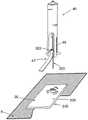
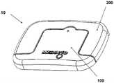
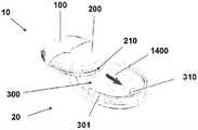
图1a至c是透视图,示出了本发明实施例的具有新颖结构的插接式液体输送装置的使用;1a to c are perspective views illustrating the use of a plug-in fluid delivery device having a novel structure according to an embodiment of the present invention;
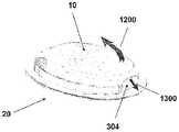
图2a至e是示意图,示出了插接单元与针头单元的连接和脱离连接;Figures 2a to e are schematic diagrams showing the connection and disconnection of the plug unit and the needle unit;
图3a至b是示意图,示出了单部件式插接单元a和两部件式插接单元b;Figures 3a to b are schematic diagrams showing a one-part plug-in unit a and a two-part plug-in unit b;
图4a至b是放大示意图,示出了采用蠕动泵送机构的单部件式插接单元a和两部件式插接单元b;Figures 4a to b are enlarged schematic views showing a one-part plug-in unit a and a two-part plug-in unit b using a peristaltic pumping mechanism;
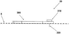
图5a至c是示意图,示出了附着至皮肤的支架和插管皮下定位;Figures 5a-c are schematic diagrams showing subcutaneous positioning of the stent and cannula attached to the skin;
图6a至c是针头单元的横截面视图(a)、上侧视图(b)和透视图(c),其中所述针头单元包含支架、插管和井(未包括穿透构件);Figures 6a-c are a cross-sectional view (a), an upper side view (b) and a perspective view (c) of the needle unit, wherein the needle unit includes the holder, cannula and well (without penetrating member);
图7a至d是针头单元的安装过程的横截面视图,其中包括支架粘附与插管部位,针头单元是单个一体式部件;Figures 7a-d are cross-sectional views of the installation process of the needle unit, including the bracket attachment and cannulation site, the needle unit being a single integral part;
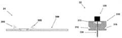
图8a至f是示意性剖视图,示出了用于支架和插管定位的插入件,其中所述针头单元在所述插入件内被隐藏;Figures 8a-f are schematic cross-sectional views showing an insert for stent and cannula positioning, wherein the needle unit is concealed within the insert;
图9a至b分别是支架的透视图(图9a)和上侧视图(图9b),在这种结构中,支架附在插入件的腿上滑动;Figures 9a-b are a perspective view (Fig. 9a) and an upper side view (Fig. 9b), respectively, of the bracket, in this configuration, the bracket slides on the legs of the insert;
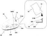
图10a至g是透视图,示出了用于支架和插管定位的插入件——支架附在插入件的腿上滑动;Figures 10a-g are perspective views showing the insert for stent and cannula positioning - the stent is attached and slid on the legs of the insert;
图11a至f是横向剖视图,示出了针头单元的安装过程,其中包括支架的附着以及插管的定位,针头单元包括支架部以及穿透匣部;Figures 11a-f are transverse cross-sectional views showing the installation of the needle unit including the attachment of the bracket and the positioning of the cannula, the needle unit including the bracket portion and the penetration cassette portion;
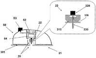
图12a至d是被构造为计算机鼠标的插入件的实施例的剖视图,插入件被用于支架和插管的定位,针头单元包括支架部以及穿透匣部;Figures 12a-d are cross-sectional views of an embodiment of an insert configured as a computer mouse, the insert being used for positioning of the holder and cannula, the needle unit including a holder portion and a penetration cassette portion;
图13a至g是示意性剖视图,示出了包括支架附着以及插管定位的用于针头单元的安装过程,其中针头单元包括支架部以及穿透匣部;Figures 13a-g are schematic cross-sectional views illustrating an installation process for a needle unit including bracket attachment and cannula positioning, wherein the needle unit includes a bracket portion and a penetration cassette portion;
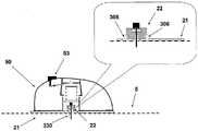
图14a至f是示意性剖视图,示出了用于支架和插管定位的插入件,其中针头单元包括支架部以及穿透匣部;Figures 14a-f are schematic cross-sectional views showing an insert for holder and cannula positioning, wherein the needle unit includes a holder portion and a penetration cassette portion;
图15是单部件式插接单元的示意性剖视图;15 is a schematic cross-sectional view of a one-part plug-in unit;
图16是两部件式插接单元的示意性剖视图;16 is a schematic cross-sectional view of a two-part plug-in unit;
图17a至f是横向剖视图,示出了插接单元与针头单元的连接和插接单元与针头单元的脱离连接;Figures 17a-f are transverse cross-sectional views showing the connection of the plug unit to the needle unit and the disconnection of the plug unit from the needle unit;
图18a至k是包括可重复使用的和一次性部件的插接单元的实施例的视图,该图示出了支架的匹配和初始化以及附着、插接单元的连接以及脱离连接;Figures 18a-k are views of an embodiment of a docking unit including reusable and disposable components showing mating and initialization of a stent and attachment, connection and detachment of the docking unit;
图19a至d是采取用于连接和脱离连接的后和前闩锁部的插接单元和针头单元的实施例的视图;Figures 19a-d are views of an embodiment of the plug unit and needle unit taking the rear and front latches for connection and disconnection;
图20a至e是插接单元和针头单元的可选实施例的视图,示出了滑动连接和脱离连接;Figures 20a-e are views of alternative embodiments of the patch unit and needle unit, showing sliding connection and disconnection;
图21a至c是插接单元和针头单元的可选实施例的横向剖视图,示出了借助于柔性闩锁部的连接与脱离连接;Figures 21a-c are transverse cross-sectional views of alternative embodiments of the patch unit and needle unit, showing connection and disconnection by means of a flexible latch;
图22a至c是插接单元与针头单元的可选实施例的横向剖视图,示出了借助于磁性力的连接和脱离连接;Figures 22a-c are transverse cross-sectional views of alternative embodiments of the plug unit and needle unit, showing attachment and detachment by means of magnetic force;
图23a至e是借助于夹具型机构所实现的插接单元-支架连接/脱离连接的横向剖视图和透视图。Figures 23a to e are cross-sectional and perspective views of a plug-in unit-bracket connection/disconnection by means of a clamp-type mechanism.
具体实施方式Detailed ways
正如出于示意性目的的附图所示,本发明的实施例涉及便携的流体输液装置。在一些实施例中,该装置可包括3个单元:远程控制单元、分配插接单元以及针头单元,其中所述针头单元附着至皮肤的任何期望部位。在其它实施例中,该装置包括两个单元:针头单元和插接单元,而没有远程控制单元。As shown in the drawings for illustrative purposes, embodiments of the present invention relate to portable fluid infusion devices. In some embodiments, the device may include 3 units: a remote control unit, a dispensing patch unit, and a needle unit, wherein the needle unit is attached to any desired part of the skin. In other embodiments, the device includes two units: a needle unit and a docking unit, without a remote control unit.
插接单元包括存储器;诸如电动DC电机或步进电机的驱动机构;形状记忆合金致动器等;和/或泵送机构,例如蠕动泵、注射器等。插接单元还可包括供电装置以及电子器件。The plug-in unit includes a memory; a drive mechanism such as an electric DC motor or a stepper motor; a shape memory alloy actuator, etc.; and/or a pumping mechanism, such as a peristaltic pump, a syringe, and the like. The plug-in unit may also include a power supply and electronics.
插接单元由一个部件或两个部件、即可重复使用的部件和一次性部件组成,并可连接至针头单元并从针头单元脱离连接。在一些实施例中,针头单元包括穿透构件,与所述穿透构件连接有插管、井和支架。The docking unit consists of one part or two parts, a reusable part and a disposable part, and can be connected to and disconnected from the needle unit. In some embodiments, the needle unit includes a penetrating member to which a cannula, a well and a stent are attached.
用于将插接单元连接至患者的身体的过程的一个实施例包括以下步骤:One embodiment of a process for connecting a docking unit to a patient's body includes the steps of:
1.针头单元插入:患者用穿透构件刺破皮肤,以允许插管定位在皮下腔隙中。刚性连接至插管的支架附着至皮肤。在插入之后,穿透构件撤出,插管仍留在体内,并且支架仍附着至皮肤。针头单元的插入可以手动地或利用插入件自动地完成。1. Needle unit insertion: The patient punctures the skin with a penetrating member to allow the cannula to be positioned in the subcutaneous space. A stent rigidly attached to the cannula is attached to the skin. After insertion, the penetrating member is withdrawn, the cannula remains in the body, and the stent remains attached to the skin. Insertion of the needle unit can be done manually or automatically using an inserter.
2.插件单元的连接:患者将插接单元的壳体连接至支架,从而插接单元的出口连接至针头单元的井。2. Connection of the plug-in unit: The patient connects the housing of the plug-in unit to the cradle so that the outlet of the plug-in unit is connected to the well of the needle unit.
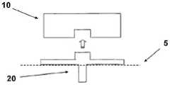
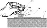
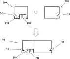
图1A至1C示出了插接单元10与针头单元20的连接以及插接单元10从针头单元20的脱离连接。图1A示出了针头单元20附着至身体。如图1A所示,还示出了支架300和井310。在将针头单元20附着至身体之后,使用者可以将插接单元10连接至针头单元20,这是通过将插接单元壳体连接至支架并将插接单元的出口(未示出)连接至井310而实现的。图1B示出了插接单元10与针头单元20彼此相连并附着至患者身体。插接单元10和针头单元20在一起连接之后构成一流体输送装置。图1C示出了插接单元10从针头单元20的脱离连接。根据患者任意的选择或按照需要,连接与脱离连接的过程可以重复多次。1A to 1C illustrate the connection of the
图2A至2E示意性示出了流体输送装置的两个单元:插接单元10和针头单元20。图2A示出了这两个单元:插接单元10和针头单元20。图2B示出了附着至皮肤5的针头单元20。图2C示出了这两个单元的连接。图2d示出了这两个相连的单元被转换到操作模式,并且图2E示出了所述单元的脱离连接。这两个单元可以反复地连接和脱离连接。2A to 2E schematically show two units of the fluid delivery device: the
图3A至3B更加详细地示出了插接单元10。所述插接单元的下侧表面上具有出口210。插接单元10可以由单个部件(图3A)或两个部件(图3B)组成。所述两部件式插接单元10由可重复使用的部件100以及具有出口210的一次性部件200组成。出口210在初始化过程中允许流体滴落并且允许在操作的过程中与针头单元20流体连通。3A to 3B show the plug-in
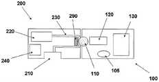
图4A至4B示出了插接单元10的实施例,其中所述插接单元采用蠕动泵作为泵送机构,以便将流体分配至患者身体。图4A示出了单部件式插接单元10。流体从在插接单元10内设置的存储器220经由输送管230被输送至出口210。蠕动泵包括设有辊的旋转齿轮110以及定子290。Figures 4A-4B illustrate an embodiment of a
轮的旋转以及辊压靠着定子290周期性地主动地通过蠕动动作而使得输送管230内的流体移动。合适的容积式泵的实施例在专利公开文献USSN 11/397115中公开,该专利公开文献全文结合在此引作参考。设置驱动机构120(例如步进电机、DC电机、SMA致动器等),所述驱动机构使得旋转轮旋转,并且通过位于插接单元10内的电子器件被控制。例如,电子器件可以是控制器、处理器和/或收发器。电子器件示意性地由附图标记130表示。还设置合适的供能装置240,其可包括一个或多个电池。输液程序可以通过远程控制器(未示出)完成,其中所述远程控制器可以实现与插接单元10内设置的收发器的双向通信联系。可选地或附加地,输液程序可以通过插接单元10上设置的手动按钮/开关105完成。Rotation of the wheel and rolling against the
图4B示出了两部件式插接单元10,其中所述两部件式插接单元由可重复使用的部件100以及一次性部件200组成。可重复使用的部件100可包括容积式泵(positivedisplacement pump),其中所述泵设有旋转轮110;驱动机构120和/或电子器件130。一次性部件200可包括存储器220、输送管230、供能装置240、出口210和/或定子290。在将可重复使用的部件100与一次性部件200相连之后可以实现流体分配。这种结构在如上所述的专利公开文献USSN 11/397115中说明。FIG. 4B shows a two-part plug-in
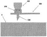
图5A至5C示出了针头单元20。图5A示出了在插入之前的针头单元20。在该步骤,针头单元20包括以下的部件:支架300、插管330、穿透构件320以及井310。图5B示出了已经附着至皮肤5之后的针头单元20。支架300借助于粘附层而附着至皮肤5,其中所述粘附层在朝向皮肤5的支架300的侧部上设置。插管330和穿透构件320被示出它们已经位于患者身体的皮下腔隙中之后。图5C示出了另一步骤,其中针头单元20仍附着至皮肤5,并且插管330仍处于皮下腔隙中,而穿透构件320被取出。The
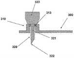
图6A至6C示出了针头单元20的其它细节:剖视图6A、上侧视图6B和透视图6C。支架300被构造为平坦的且薄的弹性片,并且可以例如由具有大约0.8mm厚度的聚合物片制成。支架300可以被构造为适于连接至插接单元10的任何期望的形状。在朝向皮肤5的支架300的底侧上可附着有胶带(即,3MTM软、整合的开口无纺布带)或者该底侧可以涂覆有生物适应性的环氧层,其使得附着至皮肤5。一突出部(例如,筒形突出部)从支架300向上伸出,并且形成井310。所述井310位于支架300的中心、边角或任何其它部位。井310的上端包括井入口311,并且井310的下端包括井出口312,插管330经过所述井出口连接至支架300。入口311由一隔片313密封,其中所述隔片可由任何自密封的材料(例如硅橡胶)制成。隔片313可由一连接管腔250被多次刺穿,其中所述连接管腔在插接单元10内设置,如下参照图17详细所述。如图7所示,隔片313在穿刺构件320撤出之后保持井310密封。Figures 6A to 6C show additional details of needle unit 20: sectional view 6A, upper side view 6B and perspective view 6C. The
图7A至7D示出了针头单元20连接至患者身体的方式。连接的过程包括插管330的插入以及随后支架300附着至皮肤5。图7A示出了连接之前的针头单元20。在该步骤,针头单元20包括插管330、支架300、井310以及穿透构件320。穿透构件320包括穿透剑部321,其具有锐利的尖端322以及抓持部323。穿透构件320刺穿自密封的隔片313,并且使得插管330朝向皮肤5移动,而锐利的尖端322刺破皮肤5并且插管330插入皮肤表面下方的皮下腔隙。图7B示出了插入之前的、即穿透构件刺穿皮肤之前并且插管插入皮下腔隙之前的针头单元20。图7C示出了插入之后的针头单元20。支架300附着至皮肤5,并且插管330和穿透构件320插入皮下。图7D示出了针头单元20附着至皮肤5并且穿透构件320从针头单元20取出。在穿透构件320撤出之后,井仍由隔片313密封。Figures 7A to 7D illustrate the manner in which the
在另一实施例中,针头单元自动地通过插入件连接至皮肤。In another embodiment, the needle unit is automatically connected to the skin through the insert.
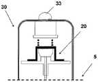
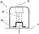
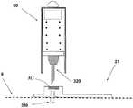
图8A至8F示出了针头单元20通过使用插入件30的自动插入。在一些实施例中,插入件30具有杯形本体。如图8A所示,插入件30包括杯形本体部31、诸如致动器的致动机构32、启动按钮/触发器33以及弹簧推压式柱塞元件34。针头单元20在插入件的本体部31内被完全隐藏。图8B示出了插入之前插入件30在皮肤5上定位的方式。借助于触发启动按钮/触发器32,针头单元20朝向皮肤5被发射。图8C示出了在触发启动按钮/触发器33之后针头单元20被发射并且附着至皮肤。图8D示出了插入件30的撤出,而将针头单元20留在原位。图8E至8F示出了可选的实施例,在该可选的实施例中,穿透构件320从针头单元20被自动地撤出。在该实施例中,插入件设有收回弹簧35,其中所述回缩弹簧使得穿透构件320收回。8A to 8F illustrate automatic insertion of
图8e示出了按钮/触发器33按下之后针头单元20的定位。收回弹簧35伸展。图8f示出了通过收回的弹簧35撤出穿透构件320,同时将针头单元20留在原位。Figure 8e shows the positioning of the
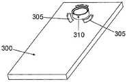
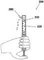
图9A至9B示出了插入件的另一实施例。图9A至9B示出了支架300,其中所述支架300设有从其伸出的井部310,并且所述井部通过一隔片313被密封。在该实施例中,支架300设有弧形离散的槽305,其中所述槽在支架的上侧面上形成并包围井部310。Figures 9A-9B show another embodiment of the insert. FIGS. 9A to 9B show a
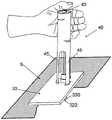
图10A示出了针头单元20,其包括支架300,而穿透构件320插入井部310内。现在,针头单元20已经准备好装载到插入件中。在图10B中,示出了针头单元20被装载到插入件40内的方式。可以看出,插入件设有腿45,其中所述腿将进入到槽305中。图10B示出了插入件30,针头单元20装载在其中,准备朝向皮肤5发射。通过触发启动按钮/触发器43,针头单元20可被朝向皮肤5发射。图10C示出了在触发启动按钮/触发器43之后针头单元20被发射并附着至皮肤5。图10D示出了包括穿透构件320的插入件40的自动撤出,而将针头单元20留在原位。因为支架300被构造为具有大约0.8mm厚度的平坦的和薄的弹性片,所以很难防止支架300的折皱并确保支架表面的均匀水平扩张,而这对于支架300的可靠的附着而言是关键的。图10E示出了设有多个条47的针头单元20的实施例,其中所述条防止针头单元20的发射过程中支架的折皱(即,折皱防止器具)。条47的一端连接至穿透构件320的抓持部323。FIG. 10A shows
各条47通过胶合剂稍微地粘附至支架300,并且横贯支架300的上侧表面扩张。优选的是,各条47位于相邻的弧形槽305之间。各条47的宽度、厚度和刚度被选择成确保在发射的过程中支架300仍处于水平位置,且并不折皱。图10F示出了设有条47的并装载在插入件40内的针头单元20。可以看出,腿45穿过槽305。条47确保了支架300没有折皱地扩张。图10G示出了插入件40被撤出的下一步骤。在插入件从支架300被排出时,条47从支架300脱离连接并仍附着至抓持部323。Each
图11A至11F示出了针头单元的另一实施例。在该结构中,针头单元包括如下的两个部件:Figures 11A to 11F show another embodiment of a needle unit. In this structure, the needle unit includes the following two components:
1.设有支架基部的支架部;1. A bracket part with a bracket base;
2.穿透匣部,其包含2. Penetrating box section, which contains
a.井部(由一自密封的隔片密封);a. Well (sealed by a self-sealing spacer);
b.插管;b. Intubation;
c.穿透构件(剑部和抓持部)。c. Penetrating members (sword and grip).
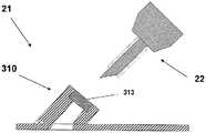
图11A示出了插入之前针头单元20的两个部件:穿透匣部22和支架部21。支架部21包括支架基部300和连接闩锁部306,其中所述连接闩锁部在支架基部300内形成的开口周围。穿透匣部22包括井部310、在所述井部内形成的横向凹部316、隔片313和穿透构件320。在穿透匣部22到达支架部21时,凹部的数量以及它们的位置允许闩锁部扣合在凹部上。借助于这样的设置,提供了穿透匣部在支架部上的可靠的固定。FIG. 11A shows the two components of the
图11B示出了包括支架基部300和三个连接闩锁部306的支架部21的俯视图,其中所述连接闩锁部在开口307周围对称地设置。图11C示出了附着至患者皮肤5的支架部21。这种附着可以通过利用粘合剂进行粘合或通过本技术领域已知的其它措施实现。应该清楚的是,粘合层应该在朝向皮肤的支架基部的侧上设置。图11D示出了穿透匣部21正到达支架部21以及闩锁部306将要扣合地接合凹部316的方式。在接合之后,穿透构件的锐利尖端322刺破皮肤5,并且插管330穿入身体。FIG. 11B shows a top view of the
图11E示出了连接至支架部21的穿透匣部22。图11F示出了从穿透匣部22取出穿透构件320。支架部21仍附着至皮肤5,并且插管330仍位于身体内。井部310的自密封隔片313允许插接单元10的连接管腔的反复的连接/脱离连接,并且防止泄漏以及污染物的渗入,如图17所示。FIG. 11E shows the penetrating
图12A至12D示出了用于两部件式插接单元20的插入件50的实施例。插入件有助于支架部21附着至皮肤5,并且允许穿透匣部22与支架基部21的自动连接。在该实施例中,支架基部21首先附着至皮肤,并且随后匣部22通过插入件50被朝向支架基部21发射,从而将支架基部21与穿透匣部22相连。图12A示出了插入件50以及两部件式针头单元20,其中所述两部件式针头单元包括支架部21和穿透匣部22。该图示出了插入之前的状况。插入件50设有致动机构52,所述致动机构设有柱塞-弹簧元件54以及启动按钮/触发器53。插入件装载有穿透匣部22。穿透匣部22包括井部310、插管330和穿透构件320。12A to 12D illustrate an embodiment of an
支架部21包括支架基部300,其上侧相对地粘附(或固定)至插入件的底侧。图12B示出了附着至患者皮肤5的支架部21。这种附着可以借助于粘合剂或借助于本技术领域已知的其它措施实现。通过将插入件50朝向皮肤按压而确保附着。图12C示出了启动按钮/触发器53被按压并且穿透匣部已经被发射之后的插入件50。在发射之后,穿透匣部22借助于闩锁部306与穿透匣部22的井部310上所形成的凹部316之间的扣合接合而连接至支架部21。图12D示出了另一步骤,其中插入件50与穿透构件320一起被自动地从皮肤5取出。支架部21仍附着至皮肤5,并且插管330仍插入身体内。The
图13A至13G示出了用于手动插入模式的针头单元20的另一实施例。在该结构中,针头单元20还包括如下的两个部分:13A to 13G illustrate another embodiment of a
1.支架部包含:1. The bracket part contains:
a.支架基部;a. The base of the stent;
b.井部;以及b. Wells; and
c.自密封的隔片;c. Self-sealing spacer;
2.穿透匣部包含:2. The penetration box part contains:
a.插管;以及a. Intubation; and
b.穿透构件(剑部和抓持部)。b. Penetrating members (sword and grip).
图13A示出了插入之前的两个部分。支架部21包括支架基部300以及井部310。穿透匣部22包括插管330、穿透构件320和隔片313。图13B示出了已经附着至患者皮肤5之后的支架部21。这种附着可以通过粘合剂或本技术领域已知的其它措施实现。图13C示出了穿透匣部22手动穿过井部310。隔片313通过剑部321被刺破。图13D示出了皮下组织内的剑部322的锐利尖端以及插管330。Figure 13A shows the two parts before insertion. The
图13E示出了穿透构件320的取出。支架部21仍附着至皮肤,并且插管330仍位于身体中。井部310的自密封的隔片313防止治疗流体的泄漏以及污染。图13F示出了穿透匣部22的另一实施例。在该实施例中,隔片313连接至插管330,并且在穿透匣部22穿过井部310的过程中被引入到井部310的上侧中。图13G示出了支架部20的另一实施例。在该实施例中,井部310处于倾斜的位置,允许以相对于皮肤的一角度插入穿透匣部22。Figure 13E shows removal of the penetrating
图14A至14F示出了用于两部件式针头单元的插入件的另一实施例。插入件60用于将匣部22插入支架基部21中。在该实施例中,支架部21首先手动地连至皮肤5,并且随后穿透匣部22通过插入件60被自动地插入。图14A示出了插入之前的插入件壳体60以及穿透匣部22。图14B示出了支架部21。插入件壳体60容纳致动机构62、弹簧加载的柱塞元件64以及穿透匣部22。穿透匣部22包括插管330和穿透构件320。支架部21包括支架300以及井部310。图14C示出了附着至患者皮肤5的支架部21。这种附着是通过粘合剂或本技术领域已知的其它措施实现的。图14D示出了安放在支架部21的井部330上的插入件壳体60。图14E示出了刺穿皮肤5之后的穿透匣部22,从而插管330已经伸入皮下组织之中。图14F示出了穿刺构件320的取出。支架部21仍附着至皮肤5,并且插管330仍位于身体中。Figures 14A to 14F illustrate another embodiment of an insert for a two-part needle unit. The
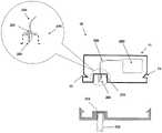
图15示出了包括单个部件的插接单元10的另一实施例。插接单元10包含壳体11,其中所述壳体11设有出口210,通过所述出口伸出一短连接管腔250,其中所述短连接管腔朝向前端变锐利。管腔的相反的后端与输送管230和存储器220流体连通。在插接单元10连接至针头单元20之后,管腔250的锐利端部进入插管330中,以提供插管330与存储器220之间的流体连通。连接管腔250在出口210内刚性固定。所述管腔的后端通过一连接器251与管230相连。壳体11设有横向槽12。在插接单元10连接至针头单元20时,连接管腔250的锐利前端刺破针头单元20的隔片313,并进入插管330中。通过这种结构,在存储器220与插管330之间实现流体连通。横向槽12允许插接单元10连接至针头单元20。Figure 15 shows another embodiment of a plug-in
图16示出了包括两个部件的插接单元10的另一实施例。可重复使用的部件100包含可多次使用的元件,而一次性部件200包含一次性元件,所述一次性元件包括存储器220和出口210。在存储器220清空之前,一直使用一次性元件。连接元件(例如连接管腔)250从一次性部件200的出口210排出。横向槽12在两个部件的外侧上设置。在将插接单元10与针头单元20相连之前,一次性部件200和可重复使用的部件100彼此相连,并且构成了如图16所示的单插接单元10。Figure 16 shows another embodiment of a plug-in
图17A至17F示出了插接单元10和针头单元20的连接和脱离连接的实施例。图17A示出了连接之前的两个单元。针头单元20附着至使用者的皮肤5,并且插管330刺入皮下组织中。在该实施例中,插接单元10包括两个部件并且包含横向槽12、出口210以及连接管腔250。针头单元20包含支架300、插管330、锚固闩锁部302、井部310和井隔片313。在插接单元10与针头单元20接触时,插接单元通过锚固闩锁部302被引导,同时维持这两个单元之间的精确对正,并且锚固两个单元。图17B示出了插接单元10,其中这是在所述插接单元已经连接至与皮肤附着的针头单元20之后,并且所述插接单元被固定,这种固定是由于在针头单元20的外周上设置的锚固闩锁部302与在插接单元10上设置的横向槽12的扣合接合而实现的。17A to 17F illustrate embodiments of the connection and disconnection of the
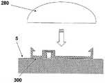
连接管腔250的锐利端部刺破隔片313,因而允许向井部310供应流体,并然后向插管330供应流体。图17C示出了插接单元10通过向回拉弹性变形的闩锁部302而被脱离连接。图17d示出了插接单元10从仍附着至皮肤5的针头单元20脱离连接,并且插管330仍位于身体中。自密封的隔片313防止体液的泄漏,并且还防止了污染。在插接单元10脱离连接时,支架300可以通过保护盖280被保护,以避免突出元件的污染以及磨损,如图17E至17F所示。The sharp end of the connecting
保护盖280可被构造为凸形的硬聚合物盖,其将支架300隐藏在其中。因而,支架300在被覆盖时并不暴露于环境。保护盖280在插接单元10的重新连接之前应该被取下。The
图18A至18K示出了流体输送装置的另一实施例,其中所述装置包括插接单元以及针头单元。在该实施例中,插接单元10包括两个部件——可重复使用部件100和一次性部件200。一次性部件设有出口210,其中所述出口并不位于一次性部件200的中央而是靠近其横向侧。图18A示出了这两个部件。一次性部件200具有U形结构,并且可重复使用的部件100具有与U形一次性部件200内的凹部匹配的方形结构。可重复使用的部件100装配有驱动机构110;诸如蠕动泵的泵送机构120以及合适的电子器件130。一次性部件200装配有存储器220;供能装置240;输送管230以及连接管腔250。管230的一端连接至存储器220,并且管的相反端连接至连接管腔250。连接管腔250位于出口210内。Figures 18A to 18K illustrate another embodiment of a fluid delivery device, wherein the device includes a docking unit and a needle unit. In this embodiment, the
参看图18B和18C,示出了存储器220被填充以及初始化完成的方式。在这些图中,示出了通过可连接至存储器220的注射器完成填充以及初始化。借助于专用的适配器还可以完成针筒与存储器的连接,其中所述专用的适配器其实施例在专利公开文献USSN 60/838660中更详细地公开,该专利公开文献结合在此引作参考。适配器允许填充注射器连接至存储器220。图18D示出了可重复使用的部件100与一次性部件200连接之后被组装的插接单元10。在连接之后,空气从存储器220、管230和连接管腔250被清除出。图18E示出了连接之前的可重复使用的部件100和一次性部件200。图18F示出了将两个部件连接之后的插接单元10的另一视图。图18g示出了附着至皮肤之前的针头单元20。针头单元20包括支架300、井部310和插管330。图18H示出了已经附着至皮肤5之后的针头单元20。图18I示出了插接单元10与针头单元20的连接;图18J示出了这两个单元正被连接(操作模式),并且图18K示出了所述单元脱离连接。Referring to Figures 18B and 18C, the manner in which the
图19A至19D示出了流体输送装置和用于连接插接单元10和针头单元20的方法的另一实施例。插接单元10包括可重复使用的部件100和一次性部件200。针头单元20包括具有升高的周壁301的支架300、井部310和支架的下侧表面上的粘附层。图19A示出了第一步骤,其中通过将插接单元10沿箭头1000朝向针头单元20移动而将插接单元10连接至针头单元20,从而支架300中的突出部12与支架300的后端2000上设置的对应凹部302接合(或者反之亦然)。19A to 19D illustrate another embodiment of a fluid delivery device and method for connecting a
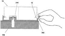
图19B示出了下一步骤,其中通过将插接单元10的前端3000沿箭头1100朝向针头单元20枢转而将两个单元相连。通过将支架300内的闩锁部304与插接单元10内的对应槽14扣合接合而实现这种连接。图19C示出了插接单元10和针头单元20已经被连接之后操作模式中的装置。在该结构中,患者可以方便地利用装置,这是因为插接单元10与针头单元20的连接和脱离连接并不影响装置的使用。患者可以给出胰岛素剂量,这是通过同时按压在可重复使用的部件100的横向壁上设置的两个按钮/开关15而实现的。图19D示出了通过沿箭头1300拉的闩锁部304的释放而实现的单元的脱离连接。插接单元10现在可以通过将其沿箭头1200枢转而被撤出。Figure 19B shows the next step in which the two units are connected by pivoting the
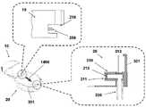
图20A至20D示出了流体输送装置以及用于将插接单元10和针头单元20相连的方法的另一实施例。插接单元10包括可重复使用的部件100以及一次性部件200。在一次性部件200内设有出口210。针头单元20包括具有抬高的侧壁301的支架300、井部310以及在支架的下侧表面上的粘附层。图20A示出了插接单元10和针头单元20通过插接单元10沿箭头1400朝向支架300的滑动而连接。20A to 20D illustrate another embodiment of a fluid delivery device and method for connecting a
图20B示出了插接单元10已经连接至针头单元20之后装置的操作模式。患者可以通过使用远程控制器或通过同时按压两个按钮/开关15而控制胰岛素剂量。FIG. 20B shows the mode of operation of the device after the
图20C示出了出口210与井部310的连接、由此将连接管腔250引入到井部310中。通过滑动实现的连接需要插接单元10上的水平指向的连接管腔250以及井部310上的横向入口311。自密封的隔片313被设置用于穿透构件插入。该隔片313密封井部310,并且其水平指向。还设有附加的自密封隔片315,其中所述附加的自密封隔片垂直指向。该隔片被设置用于连接管腔250的穿透。FIG. 20C shows the connection of the
图20D示出了连接管腔250,其中所述连接管腔刺破井的隔片313,允许与存储器的流体连通。图20E示出了插接单元10从针头单元20的脱离连接,这是通过沿箭头1500释放闩锁部304并且之后沿箭头1600滑动撤出插接单元10而实现的。Figure 20D shows the connecting
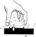
图21A至21C示出了流体输送装置以及用于连接插接单元10和针头单元20的方法的另一实施例。插接单元10包括可重复使用的部件100和一次性部件200。插接单元10设有弹性可变形的闩锁部16,其中所述闩锁部在插接单元10的周边上设置。针头单元20包括支架300和井部310。槽17在支架300的周边上设置。槽17被构造成匹配闩锁部16,从而可以在它们之间实现扣合接合。插接单元10的周壁2100是可弹性变形的,从而闩锁部16可以容易地被向内压。图21A示出了两个单元被带到一起并将要通过闩锁部16与槽17的扣合接合而相连。图21B示出了借助于闩锁部16在槽17上的扣合而固定在支架300上的插接单元10。图21C示出了通过以下方式实现的插接单元10的脱离连接,即挤压插接单元10的壁,从而闩锁部16向内弹性移动,以允许它们从槽17脱离接合。21A to 21C illustrate another embodiment of a fluid delivery device and method for connecting a
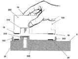
图22A至22C示出了流体输送装置以及用于将插接单元10与针头单元20相连的方法的另一实施例。在该实施例中,插接单元10与针头单元20通过磁性力相连。插接单元10包括可重复使用的部件100和一次性部件200。针头单元20包括支架300以及井部310。图22A示出了插接单元10被带至针头单元从而将其与针头单元20相连。磁性条18在插接单元10的底侧表面的多个部位上设置。磁性条28在支架300的上侧的对应部位上设置。支架300被构造成具有向上伸出的并与井部310的外侧表面平行的支承壁302。插接单元10的出口210被构造成匹配井部310的周边。借助于支承壁302和井部310,插接单元10可以正确地在支架300上被定位。图22B示出了两个部件之间的连接通过磁性条18和28的磁性吸引力被维持。图22C示出了插接单元10从针头单元20的脱离连接。这可以通过将诸如硬币或针的薄分离器具9安放在插接单元10上设置的专用凹部19内而实现。原理上,可以利用除了磁性条以外的任何其它合适的连接材料、例如
图23A至23E示出了流体输送装置以及用于将插接单元10与针头单元20相连的方法的另一实施例。在该实施例中,插头单元10可借助于夹具形机构(其实例以下所述)固定在针头单元20上,其中所述夹具形机构根据某些实施例是这样一种结构,所述结构利用了一个或多个卡爪/凹部/凹槽以接收对应的旋转臂(臂)——至少一部分旋转臂通过对应的凹部被捕获,因而将插接单元“捕获”在支架内。因此,插接单元10包括可重复使用的部件100以及一次性部件200。针头单元20包括支架300以及井部310。端接有带有钩的端部303的旋转臂302在针头单元20上设置,并且对应的凹槽12在插接单元10上设置。图23A示出了插接单元10和针头单元20通过臂302的连接。图23B示出了插接单元10通过臂302被固定,其中所述臂已经被旋转,从而带有钩的端部303进入凹槽12、303中,以将插接单元锁定在支架上。23A to 23E illustrate another embodiment of a fluid delivery device and method for connecting a
图23C示出了插接单元10的脱离连接,这是通过旋转臂302直至带有钩的端部303从凹槽12排出并释放插接单元10而实现的。图23D示出了从支架被释放并脱离连接的插接单元10的透视图。图23E示出了固定在支架300上的插接单元10的透视图。FIG. 23C shows the disengagement of the plug-in
因而,可以看出提供了用于将治疗流体输送到身体中的装置、系统和方法。尽管已经在此详细地公开了特定的实施例,但是仅仅是出于示意性的目的进行了公开,并且并不限于权利要求书的范围。特别地,根据本发明可以清楚,在不脱离由权利要求书所限定的本发明的精神和范围的前提下可以实现各种不同的替换、改变和改型。其它方面、优点和改型可以被考虑在权利要求书中。权利要求书体现了在此所公开的本发明。也考虑了其它、未要求保护的发明。发明人将追求这种发明的权利归入到随后的权利要求书中。Thus, it can be seen that devices, systems and methods for delivering therapeutic fluids into the body are provided. Although specific embodiments have been disclosed in detail herein, they have been disclosed for illustrative purposes only, and are not intended to limit the scope of the claims. In particular, it is apparent from the present invention that various substitutions, changes and modifications can be made without departing from the spirit and scope of the invention as defined by the appended claims. Other aspects, advantages, and modifications may be contemplated in the claims. The claims embody the invention disclosed herein. Other, unclaimed inventions are also contemplated. The inventor's right to pursue such an invention is relegated to the following claims.
与本发明有关的所有专利文件、专利申请、文章和其它出版的和/或未出版的文献结合在此引作参考。All patent documents, patent applications, articles and other published and/or unpublished references pertaining to the present invention are incorporated herein by reference.
Claims (26)
Translated fromChinesePriority Applications (1)
| Application Number | Priority Date | Filing Date | Title |
|---|---|---|---|
| CN202210376348.5ACN114712615B (en) | 2006-12-22 | 2007-12-20 | Systems and devices for maintaining delivery of therapeutic fluids |
Applications Claiming Priority (4)
| Application Number | Priority Date | Filing Date | Title |
|---|---|---|---|
| US87667906P | 2006-12-22 | 2006-12-22 | |
| US60/876,679 | 2006-12-22 | ||
| CN202210376348.5ACN114712615B (en) | 2006-12-22 | 2007-12-20 | Systems and devices for maintaining delivery of therapeutic fluids |
| CNA2007800471135ACN101573151A (en) | 2006-12-22 | 2007-12-20 | System and device for sustained delivery of therapeutic fluid |
Related Parent Applications (1)
| Application Number | Title | Priority Date | Filing Date |
|---|---|---|---|
| CNA2007800471135ADivisionCN101573151A (en) | 2006-12-22 | 2007-12-20 | System and device for sustained delivery of therapeutic fluid |
Publications (2)
| Publication Number | Publication Date |
|---|---|
| CN114712615Atrue CN114712615A (en) | 2022-07-08 |
| CN114712615B CN114712615B (en) | 2024-07-23 |
Family
ID=39185937
Family Applications (4)
| Application Number | Title | Priority Date | Filing Date |
|---|---|---|---|
| CNA2007800471135APendingCN101573151A (en) | 2006-12-22 | 2007-12-20 | System and device for sustained delivery of therapeutic fluid |
| CN202410722004.4APendingCN118576817A (en) | 2006-12-22 | 2007-12-20 | Systems and devices for maintaining delivery of therapeutic fluids |
| CN202210376348.5AActiveCN114712615B (en) | 2006-12-22 | 2007-12-20 | Systems and devices for maintaining delivery of therapeutic fluids |
| CN201510849967.1AActiveCN105327418B (en) | 2006-12-22 | 2007-12-20 | System and device for sustained delivery of therapeutic fluid |
Family Applications Before (2)
| Application Number | Title | Priority Date | Filing Date |
|---|---|---|---|
| CNA2007800471135APendingCN101573151A (en) | 2006-12-22 | 2007-12-20 | System and device for sustained delivery of therapeutic fluid |
| CN202410722004.4APendingCN118576817A (en) | 2006-12-22 | 2007-12-20 | Systems and devices for maintaining delivery of therapeutic fluids |
Family Applications After (1)
| Application Number | Title | Priority Date | Filing Date |
|---|---|---|---|
| CN201510849967.1AActiveCN105327418B (en) | 2006-12-22 | 2007-12-20 | System and device for sustained delivery of therapeutic fluid |
Country Status (14)
| Country | Link |
|---|---|
| US (3) | US9662440B2 (en) |
| EP (5) | EP3400979B1 (en) |
| JP (1) | JP2011507555A (en) |
| CN (4) | CN101573151A (en) |
| AU (1) | AU2007337684A1 (en) |
| DK (4) | DK3632488T3 (en) |
| ES (4) | ES2764202T3 (en) |
| FI (2) | FI3998095T3 (en) |
| HU (2) | HUE061916T2 (en) |
| LT (2) | LT3632488T (en) |
| PL (4) | PL2125077T3 (en) |
| PT (2) | PT3632488T (en) |
| SI (4) | SI3400979T1 (en) |
| WO (1) | WO2008078318A2 (en) |
Families Citing this family (190)
| Publication number | Priority date | Publication date | Assignee | Title |
|---|---|---|---|---|
| US9788771B2 (en) | 2006-10-23 | 2017-10-17 | Abbott Diabetes Care Inc. | Variable speed sensor insertion devices and methods of use |
| EP1762259B2 (en) | 2005-09-12 | 2025-01-01 | Unomedical A/S | Inserter for an infusion set with a first and second spring units |
| US8475408B2 (en) | 2005-11-08 | 2013-07-02 | Asante Solutions, Inc. | Infusion pump system |
| EP3165247B1 (en) | 2006-02-09 | 2020-10-28 | DEKA Products Limited Partnership | Pumping fluid delivery systems and methods using force application assembley |
| DK2365452T3 (en)* | 2006-07-07 | 2020-11-16 | Hoffmann La Roche | Liquid administration device and methods of operating the same |
| US7682338B2 (en) | 2006-08-23 | 2010-03-23 | Medtronic Minimed, Inc. | Infusion medium delivery system, device and method with needle inserter and needle inserter device and method |
| DK3632488T3 (en) | 2006-12-22 | 2023-06-06 | Hoffmann La Roche | Device for continuous administration of a therapeutic fluid |
| JP5624322B2 (en)* | 2006-12-22 | 2014-11-12 | エフ.ホフマン−ラ ロシュアーゲーF.Hoffmann−La Roche Aktiengesellschaft | Liquid supply with in-vivo electrochemical analyte sensing |
| WO2008080990A1 (en)* | 2006-12-29 | 2008-07-10 | Disetronic Licensing Ag | Infusion device that can be worn outside the body |
| US20080234663A1 (en)* | 2007-03-19 | 2008-09-25 | Ofer Yodfat | Method for Selecting Bolus Doses in a Drug Delivery System |
| ES2973440T3 (en)* | 2007-04-10 | 2024-06-20 | Hoffmann La Roche | Apparatus and procedure for pumping fluid |
| WO2009056981A2 (en)* | 2007-05-07 | 2009-05-07 | Medingo Ltd. | Reciprocating delivery of fluids to the body with analyte concentration monitoring |
| US9138534B2 (en)* | 2007-05-11 | 2015-09-22 | Roche Diabetes Care, Inc. | Positive displacement pump |
| US20080319394A1 (en)* | 2007-06-11 | 2008-12-25 | Medingo, Ltd. | Portable infusion device with reduced level of operational noise |
| ES2576639T3 (en)* | 2007-06-20 | 2016-07-08 | F.Hoffmann-La Roche Ag | Method and device to assess the ratio of carbohydrates to insulin |
| ES2767265T3 (en) | 2007-06-21 | 2020-06-17 | Hoffmann La Roche | Device and procedure to prevent hypoglycemia |
| EP2165320A2 (en)* | 2007-06-22 | 2010-03-24 | Medingo Ltd. | Communications for medicinal fluid delivery system |
| US8002752B2 (en)* | 2007-06-25 | 2011-08-23 | Medingo, Ltd. | Protector apparatus |
| EP2174248B1 (en)* | 2007-06-25 | 2016-10-05 | Roche Diabetes Care GmbH | A method system and device for assessing insulin sensitivity |
| US9173991B2 (en)* | 2007-07-02 | 2015-11-03 | Roche Diabetes Care, Inc. | Device for drug delivery |
| US8911423B2 (en)* | 2007-07-12 | 2014-12-16 | Roche Diagnostics Operations, Inc. | Systems and methods for glycemic control during pump disconnection |
| EP2180821B1 (en)* | 2007-07-20 | 2014-05-07 | Roche Diagnostics GmbH | Energy supply for fluid dispensing device |
| EP2185220B1 (en)* | 2007-08-01 | 2019-04-10 | Roche Diabetes Care GmbH | A device for drug delivery |
| US8147446B2 (en)* | 2007-08-01 | 2012-04-03 | Medingo Ltd. | Detachable portable infusion device |
| AU2008281381A1 (en) | 2007-08-01 | 2009-02-05 | F.Hoffmann-La Roche Ag | Portable infusion device provided with means for monitoring and controlling fluid delivery |
| WO2009016638A1 (en)* | 2007-08-01 | 2009-02-05 | Medingo Ltd. | Device for facilitating infusion of therapeutic fluids and sensing of bodily analytes |
| EP2200677A1 (en) | 2007-09-17 | 2010-06-30 | ICU Medical, Inc. | Insertion devices for infusion devices |
| US7967795B1 (en) | 2010-01-19 | 2011-06-28 | Lamodel Ltd. | Cartridge interface assembly with driving plunger |
| US10420880B2 (en) | 2007-10-02 | 2019-09-24 | West Pharma. Services IL, Ltd. | Key for securing components of a drug delivery system during assembly and/or transport and methods of using same |
| BRPI0817907B8 (en) | 2007-10-02 | 2021-06-22 | Lamodel Ltd | apparatus for administering a substance to an individual |
| US9345836B2 (en) | 2007-10-02 | 2016-05-24 | Medimop Medical Projects Ltd. | Disengagement resistant telescoping assembly and unidirectional method of assembly for such |
| US9656019B2 (en) | 2007-10-02 | 2017-05-23 | Medimop Medical Projects Ltd. | Apparatuses for securing components of a drug delivery system during transport and methods of using same |
| US20100268043A1 (en)* | 2007-11-07 | 2010-10-21 | Ofer Yodfat | Device and Method for Preventing Diabetic Complications |
| WO2009060433A1 (en)* | 2007-11-09 | 2009-05-14 | Medingo Ltd. | Assessing residual insulin time |
| DE102007055636A1 (en)* | 2007-11-21 | 2009-05-28 | Robert Bosch Gmbh | Drug dosing device for administering a liquid medicament |
| JP2011504129A (en)* | 2007-11-21 | 2011-02-03 | メディンゴ・リミテッド | Analyte monitoring and fluid dispensing system |
| US8500692B2 (en)* | 2007-12-21 | 2013-08-06 | Medingo Ltd. | Devices and methods for powering a medical device |
| DK2230991T3 (en)* | 2007-12-26 | 2018-08-06 | Hoffmann La Roche | Glycemic Control System |
| WO2009081403A2 (en)* | 2007-12-26 | 2009-07-02 | Medingo Ltd. | Maintaining glycemic control during exercise |
| US10188787B2 (en) | 2007-12-31 | 2019-01-29 | Deka Products Limited Partnership | Apparatus, system and method for fluid delivery |
| CA2919786C (en) | 2007-12-31 | 2019-10-22 | Deka Products Limited Partnership | Infusion pump assembly |
| US10080704B2 (en) | 2007-12-31 | 2018-09-25 | Deka Products Limited Partnership | Apparatus, system and method for fluid delivery |
| US9456955B2 (en) | 2007-12-31 | 2016-10-04 | Deka Products Limited Partnership | Apparatus, system and method for fluid delivery |
| US9526830B2 (en) | 2007-12-31 | 2016-12-27 | Deka Products Limited Partnership | Wearable pump assembly |
| US8900188B2 (en) | 2007-12-31 | 2014-12-02 | Deka Products Limited Partnership | Split ring resonator antenna adapted for use in wirelessly controlled medical device |
| US11357910B2 (en)* | 2007-12-31 | 2022-06-14 | Deka Products Limited Partnership | Pump assembly with switch |
| US8881774B2 (en) | 2007-12-31 | 2014-11-11 | Deka Research & Development Corp. | Apparatus, system and method for fluid delivery |
| US8845613B2 (en) | 2008-01-28 | 2014-09-30 | Roche Diagnostics Operations, Inc. | Bolus dose determination for a therapeutic fluid dispensing system |
| EP2271384B1 (en) | 2008-03-10 | 2018-04-18 | Roche Diabetes Care GmbH | Portable infusion and sensing device with battery charging and data transferring mechanisms |
| WO2009113075A1 (en)* | 2008-03-12 | 2009-09-17 | Medingo Ltd. | Devices and methods for improving accuracy of fluid delivery |
| DK3260145T3 (en) | 2008-04-09 | 2020-02-17 | Hoffmann La Roche | Fluid level sensor for a modular, skin adhesive medical fluid delivery system |
| WO2009133558A2 (en)* | 2008-04-29 | 2009-11-05 | Medingo Ltd. | A method for selecting bolus doses and bolus delivery patterns in a drug delivery device |
| WO2009133557A2 (en)* | 2008-04-29 | 2009-11-05 | Medingo Ltd. | Methods and apparatuses for selecting a bolus delivery pattern in a drug delivery device |
| US20110071765A1 (en)* | 2008-05-16 | 2011-03-24 | Ofer Yodfat | Device and Method for Alleviating Postprandial Hyperglycemia |
| EP2303359B1 (en) | 2008-05-29 | 2020-02-26 | Roche Diabetes Care GmbH | Modular medical infusion device with means for identification/authentication between its components |
| US7959598B2 (en) | 2008-08-20 | 2011-06-14 | Asante Solutions, Inc. | Infusion pump systems and methods |
| JP5298699B2 (en)* | 2008-08-20 | 2013-09-25 | セイコーエプソン株式会社 | Control unit, tube unit, micro pump |
| DK2626093T3 (en)* | 2008-08-28 | 2014-02-24 | Hoffmann La Roche | DEVICE FOR INCREASING HYPODERMIC insulin absorption |
| WO2010026580A2 (en) | 2008-09-05 | 2010-03-11 | Medingo Ltd. | Auditory notification device |
| EP2350894B1 (en)* | 2008-09-11 | 2019-07-03 | Roche Diabetes Care GmbH | Methods and devices for tailoring a bolus delivery pattern |
| US12097357B2 (en) | 2008-09-15 | 2024-09-24 | West Pharma. Services IL, Ltd. | Stabilized pen injector |
| US9393369B2 (en) | 2008-09-15 | 2016-07-19 | Medimop Medical Projects Ltd. | Stabilized pen injector |
| JP5282508B2 (en) | 2008-09-29 | 2013-09-04 | セイコーエプソン株式会社 | Control unit, tube unit, micro pump |
| EP2370125B1 (en) | 2008-10-07 | 2019-04-10 | Roche Diabetes Care GmbH | Skin securable drug delivery device with a shock absorbing protective shield |
| US8632497B2 (en)* | 2008-10-09 | 2014-01-21 | Roche Diagnostics Operations Inc. | Skin securable drug delivery device with a shock absorbing protective shield |
| US9566383B2 (en) | 2008-10-16 | 2017-02-14 | Roche Diabetes Care, Inc. | Method and system for adaptive communication transmission |
| EP2379133A1 (en) | 2008-11-11 | 2011-10-26 | Medingo Ltd. | Modular fluid delivery device with quick-release /connect mechanism for drive screw |
| JP5195368B2 (en) | 2008-12-05 | 2013-05-08 | セイコーエプソン株式会社 | Tube unit, control unit, micro pump |
| EP2201968A1 (en) | 2008-12-24 | 2010-06-30 | Roche Diagnostics GmbH | Insertion system and insertion device |
| WO2010076792A1 (en) | 2008-12-31 | 2010-07-08 | Medingo Ltd. | Portable medical fluid delivery device with drive screw articulated with reservoir plunger |
| EP2414028A4 (en)* | 2009-03-30 | 2012-09-19 | Medingo Ltd | DEVICES AND METHOD FOR INCREASING THE ACTIVE ABSORPTION RATE |
| US20110125178A1 (en)* | 2009-05-15 | 2011-05-26 | Michael Drews | Devices, methods and kits for forming tracts in tissue |
| DK2437731T3 (en) | 2009-06-04 | 2018-01-22 | Hoffmann La Roche | DEVICE AND PROCEDURE FOR ADJUSTING BASAL SUBMISSION PROFILE |
| EP2442843A4 (en) | 2009-06-14 | 2012-11-28 | Medingo Ltd | DEVICE AND METHOD FOR DETECTING MALFUNCTION IN A MEDICAMENTAL DISPENSER |
| EP2453972B1 (en) | 2009-07-16 | 2014-01-15 | Medingo Ltd. | A device for accurate infusion of fluids |
| US8547239B2 (en) | 2009-08-18 | 2013-10-01 | Cequr Sa | Methods for detecting failure states in a medicine delivery device |
| US8672873B2 (en) | 2009-08-18 | 2014-03-18 | Cequr Sa | Medicine delivery device having detachable pressure sensing unit |
| US8900190B2 (en) | 2009-09-02 | 2014-12-02 | Medtronic Minimed, Inc. | Insertion device systems and methods |
| US8932256B2 (en) | 2009-09-02 | 2015-01-13 | Medtronic Minimed, Inc. | Insertion device systems and methods |
| USD810279S1 (en) | 2009-09-15 | 2018-02-13 | Medimop Medical Projects Ltd. | Injector device |
| US10071196B2 (en) | 2012-05-15 | 2018-09-11 | West Pharma. Services IL, Ltd. | Method for selectively powering a battery-operated drug-delivery device and device therefor |
| US8157769B2 (en) | 2009-09-15 | 2012-04-17 | Medimop Medical Projects Ltd. | Cartridge insertion assembly for drug delivery system |
| US10071198B2 (en) | 2012-11-02 | 2018-09-11 | West Pharma. Servicees IL, Ltd. | Adhesive structure for medical device |
| US8734391B2 (en) | 2009-10-30 | 2014-05-27 | Roche Diagnostics Operations, Inc. | Systems, methods and devices for adjusting the insertion depth of a cannula associated with a portable therapeutic device |
| ATE553800T1 (en) | 2009-11-26 | 2012-05-15 | Hoffmann La Roche | EXTERNALLY TRIGGERABLE CANNULA ARRANGEMENT |
| AU2010325518A1 (en)* | 2009-11-30 | 2012-06-14 | F.Hoffmann-La Roche Ag | Analyte monitoring and fluid dispensing system |
| US8998840B2 (en)* | 2009-12-30 | 2015-04-07 | Medtronic Minimed, Inc. | Connection and alignment systems and methods |
| US8998858B2 (en) | 2009-12-29 | 2015-04-07 | Medtronic Minimed, Inc. | Alignment and connection systems and methods |
| US9039653B2 (en) | 2009-12-29 | 2015-05-26 | Medtronic Minimed, Inc. | Retention systems and methods |
| US8858500B2 (en) | 2009-12-30 | 2014-10-14 | Medtronic Minimed, Inc. | Engagement and sensing systems and methods |
| US8435209B2 (en) | 2009-12-30 | 2013-05-07 | Medtronic Minimed, Inc. | Connection and alignment detection systems and methods |
| US11497850B2 (en) | 2009-12-30 | 2022-11-15 | Medtronic Minimed, Inc. | Connection and alignment detection systems and methods |
| US9421321B2 (en) | 2009-12-30 | 2016-08-23 | Medtronic Minimed, Inc. | Connection and alignment systems and methods |
| US20120215163A1 (en) | 2009-12-30 | 2012-08-23 | Medtronic Minimed, Inc. | Sensing systems and methods |
| US8348898B2 (en) | 2010-01-19 | 2013-01-08 | Medimop Medical Projects Ltd. | Automatic needle for drug pump |
| JP5671824B2 (en)* | 2010-03-25 | 2015-02-18 | セイコーエプソン株式会社 | Fluid injection system |
| KR20130018783A (en) | 2010-03-30 | 2013-02-25 | 우노메디컬 에이/에스 | Medical device |
| EP2569031B1 (en) | 2010-05-10 | 2017-10-11 | Medimop Medical Projects Ltd. | Low volume accurate injector |
| US9216249B2 (en) | 2010-09-24 | 2015-12-22 | Perqflo, Llc | Infusion pumps |
| US8915879B2 (en) | 2010-09-24 | 2014-12-23 | Perqflo, Llc | Infusion pumps |
| US9498573B2 (en) | 2010-09-24 | 2016-11-22 | Perqflo, Llc | Infusion pumps |
| US9381300B2 (en) | 2010-09-24 | 2016-07-05 | Perqflo, Llc | Infusion pumps |
| WO2012059209A1 (en) | 2010-11-01 | 2012-05-10 | Roche Diagnostics Gmbh | Fluid dispensing device with a flow detector |
| US8905972B2 (en) | 2010-11-20 | 2014-12-09 | Perqflo, Llc | Infusion pumps |
| CA2820070A1 (en)* | 2011-01-27 | 2012-08-02 | Medtronic Minimed, Inc. | Insertion device systems and methods |
| WO2012123274A1 (en) | 2011-03-14 | 2012-09-20 | Unomedical A/S | Inserter system with transport protection |
| USD702834S1 (en) | 2011-03-22 | 2014-04-15 | Medimop Medical Projects Ltd. | Cartridge for use in injection device |
| WO2013050277A1 (en) | 2011-10-05 | 2013-04-11 | Unomedical A/S | Inserter for simultaneous insertion of multiple transcutaneous parts |
| DK3045187T3 (en) | 2011-10-14 | 2019-06-11 | Amgen Inc | INJECTOR AND COLLECTION PROCEDURE |
| EP2583715A1 (en) | 2011-10-19 | 2013-04-24 | Unomedical A/S | Infusion tube system and method for manufacture |
| KR20140135736A (en)* | 2012-03-12 | 2014-11-26 | 유니트랙트 시린지 피티와이 엘티디 | Fill-finish cartridges for sterile fluid pathway assemblies and drug delivery devices incorporating fill-finish cartridges |
| US9072827B2 (en) | 2012-03-26 | 2015-07-07 | Medimop Medical Projects Ltd. | Fail safe point protector for needle safety flap |
| EP2650031A1 (en) | 2012-04-11 | 2013-10-16 | PharmaSens AG | Manual pressure activated application mechanism |
| US20130317438A1 (en) | 2012-05-25 | 2013-11-28 | Arstasis, Inc. | Vascular access configuration |
| HK1210974A1 (en)* | 2012-08-20 | 2016-05-13 | F. Hoffmann-La Roche Ag | Therapeutic system with an adaptor for an infusion set |
| US9731069B2 (en) | 2012-09-27 | 2017-08-15 | Becton, Dickinson And Company | Perpendicular infusion set and disposable inserter |
| US9421323B2 (en) | 2013-01-03 | 2016-08-23 | Medimop Medical Projects Ltd. | Door and doorstop for portable one use drug delivery apparatus |
| JP6098250B2 (en)* | 2013-03-14 | 2017-03-22 | セイコーエプソン株式会社 | Liquid transport device |
| SG11201507878SA (en) | 2013-03-22 | 2015-10-29 | Amgen Inc | Injector and method of assembly |
| US9011164B2 (en) | 2013-04-30 | 2015-04-21 | Medimop Medical Projects Ltd. | Clip contact for easy installation of printed circuit board PCB |
| US9561324B2 (en) | 2013-07-19 | 2017-02-07 | Bigfoot Biomedical, Inc. | Infusion pump system and method |
| BR112016008946B1 (en) | 2013-10-24 | 2022-12-27 | Amgen Inc | INJECTORS AND METHOD FOR ASSEMBLING THE INJECTORS |
| US10569015B2 (en) | 2013-12-02 | 2020-02-25 | Bigfoot Biomedical, Inc. | Infusion pump system and method |
| JP2015167709A (en)* | 2014-03-07 | 2015-09-28 | セイコーエプソン株式会社 | liquid transport device and pump unit |
| US10279106B1 (en) | 2014-05-08 | 2019-05-07 | Tandem Diabetes Care, Inc. | Insulin patch pump |
| EP3145561A1 (en) | 2014-05-20 | 2017-03-29 | Cequr SA | Medicine delivery device with restricted access filling port |
| US12178992B2 (en) | 2014-09-30 | 2024-12-31 | Medtronic Minimed, Inc. | Different disposable assemblies for the same reusable assembly |
| US10159786B2 (en) | 2014-09-30 | 2018-12-25 | Perqflo, Llc | Hybrid ambulatory infusion pumps |
| EP3034115A1 (en)* | 2014-12-19 | 2016-06-22 | Sanofi-Aventis Deutschland GmbH | Needle interface |
| US10737016B2 (en) | 2015-02-18 | 2020-08-11 | Medtronic Minimed, Inc. | Ambulatory infusion pumps and reservoir assemblies for use with same |
| US10293120B2 (en) | 2015-04-10 | 2019-05-21 | West Pharma. Services IL, Ltd. | Redundant injection device status indication |
| US9878097B2 (en) | 2015-04-29 | 2018-01-30 | Bigfoot Biomedical, Inc. | Operating an infusion pump system |
| US9993595B2 (en) | 2015-05-18 | 2018-06-12 | Tandem Diabetes Care, Inc. | Patch pump cartridge attachment |
| PL3097933T3 (en)* | 2015-05-26 | 2020-03-31 | F. Hoffmann-La Roche Ag | Cartridge and inserter for a medical system |
| US10149943B2 (en) | 2015-05-29 | 2018-12-11 | West Pharma. Services IL, Ltd. | Linear rotation stabilizer for a telescoping syringe stopper driverdriving assembly |
| CN113181477B (en) | 2015-06-04 | 2023-07-14 | 麦迪麦珀医疗工程有限公司 | Cartridge insertion for drug delivery device |
| US10279107B2 (en) | 2015-08-20 | 2019-05-07 | Tandem Diabetes Care, Inc. | Drive mechanism for infusion pump |
| US10576207B2 (en) | 2015-10-09 | 2020-03-03 | West Pharma. Services IL, Ltd. | Angled syringe patch injector |
| US9987432B2 (en) | 2015-09-22 | 2018-06-05 | West Pharma. Services IL, Ltd. | Rotation resistant friction adapter for plunger driver of drug delivery device |
| US11065381B2 (en) | 2015-10-05 | 2021-07-20 | E3D A.C.A.L. | Infusion pump device and method for use thereof |
| US11318254B2 (en) | 2015-10-09 | 2022-05-03 | West Pharma. Services IL, Ltd. | Injector needle cap remover |
| AU2016385454B2 (en) | 2016-01-05 | 2021-12-16 | Bigfoot Biomedical, Inc. | Operating multi-modal medicine delivery systems |
| HK1256995A1 (en) | 2016-01-14 | 2019-10-11 | Bigfoot Biomedical, Inc. | Occlusion resolution in medication delivery devices, systems, and methods |
| CN108778370B (en) | 2016-01-19 | 2021-10-08 | 优诺医疗有限公司 | Cannula and infusion set |
| EP3711793B1 (en) | 2016-01-21 | 2021-12-01 | West Pharma Services IL, Ltd. | A method of connecting a cartridge to an automatic injector |
| JP6885960B2 (en) | 2016-01-21 | 2021-06-16 | ウェスト ファーマ サービシーズ イスラエル リミテッド | Drug delivery device with visual indicators |
| US10646643B2 (en) | 2016-01-21 | 2020-05-12 | West Pharma. Services IL, Ltd. | Needle insertion and retraction mechanism |
| AU366963S (en)* | 2016-01-21 | 2016-02-09 | Cpie Pharmacy Services R & D Pty Ltd | Infusion pump |
| USD835261S1 (en)* | 2016-01-22 | 2018-12-04 | ViCentra, B.V. | Pump and cartridge set for portable patient infusion system |
| EP3413954B1 (en) | 2016-02-12 | 2025-09-03 | Medtronic MiniMed, Inc. | Ambulatory infusion pump and assemblies for use with same |
| US11389597B2 (en) | 2016-03-16 | 2022-07-19 | West Pharma. Services IL, Ltd. | Staged telescopic screw assembly having different visual indicators |
| EP4442297A3 (en) | 2016-04-29 | 2025-01-01 | ICU Medical, Inc. | Subcutaneous insertion systems, devices and related methods |
| CN109310831B (en) | 2016-06-02 | 2021-11-23 | 西医药服务以色列有限公司 | Three position needle retraction |
| US11338090B2 (en) | 2016-08-01 | 2022-05-24 | West Pharma. Services IL, Ltd. | Anti-rotation cartridge pin |
| JP7059251B2 (en) | 2016-08-01 | 2022-04-25 | ウェスト ファーマ サービシーズ イスラエル リミテッド | A spring that prevents the door from closing halfway |
| US10926025B2 (en) | 2016-09-15 | 2021-02-23 | Tandem Diabetes Care, Inc. | Vial supporter for medicament pump |
| WO2018132578A1 (en) | 2017-01-11 | 2018-07-19 | Tandem Diabetes Care, Inc. | Electromagnetic signal-based infusion pump control |
| US11071478B2 (en) | 2017-01-23 | 2021-07-27 | Abbott Diabetes Care Inc. | Systems, devices and methods for analyte sensor insertion |
| DE102017201434A1 (en)* | 2017-01-30 | 2018-08-02 | Fresenius Medical Care Deutschland Gmbh | Kanülierautomat |
| KR102388991B1 (en)* | 2017-05-22 | 2022-04-22 | 삼성전자주식회사 | Biosensor, manufacturing method of biosensor and biosignal measuring apparatus |
| EP3630226A1 (en) | 2017-05-30 | 2020-04-08 | West Pharma. Services Il, Ltd. | Modular drive train for wearable injector |
| JP7126544B2 (en)* | 2017-07-07 | 2022-08-26 | ニューロダーム リミテッド | Vial adapter, method and filling system for filling a reservoir of a drug delivery device with a flowable drug using the vial adapter |
| US20230123806A1 (en) | 2017-07-07 | 2023-04-20 | Neuroderm, Ltd. | Device for subcutaneous delivery of fluid medicament |
| JP7402799B2 (en) | 2017-12-22 | 2023-12-21 | ウェスト ファーマ サービシーズ イスラエル リミテッド | Syringes available with different cartridge sizes |
| CN111936182B (en) | 2018-02-05 | 2022-08-23 | 坦德姆糖尿病护理股份有限公司 | Method and system for detecting the condition of an infusion pump |
| HUE063930T2 (en)* | 2018-12-21 | 2024-02-28 | Hoffmann La Roche | A medical device that can be applied to the skin |
| WO2020142544A1 (en) | 2019-01-04 | 2020-07-09 | Enable Injections, Inc. | Medical fluid injection apparatus and method with detachable patch and monitoring |
| US11109800B2 (en) | 2019-01-04 | 2021-09-07 | Enable Injections, Inc. | Medical fluid injection apparatus and method with detachable patch and monitoring |
| US10888655B2 (en) | 2019-02-19 | 2021-01-12 | Tandem Diabetes Care, Inc. | System and method of pairing an infusion pump with a remote control device |
| EP3946514A4 (en) | 2019-03-26 | 2022-12-21 | Tandem Diabetes Care, Inc. | Method of pairing an infusion pump with a remote control device |
| US11458292B2 (en) | 2019-05-20 | 2022-10-04 | Unomedical A/S | Rotatable infusion device and methods thereof |
| KR102780302B1 (en) | 2019-09-03 | 2025-03-14 | 삼성전자주식회사 | Electronic device for measuring bio-signals |
| EP4028110A1 (en)* | 2019-09-23 | 2022-07-20 | Bard Peripheral Vascular, Inc. | Vascular access systems and methods thereof |
| AU2021242403A1 (en) | 2020-03-23 | 2022-05-26 | Terumo Kabushiki Kaisha | Medicinal solution administration device |
| CA3188510A1 (en) | 2020-08-31 | 2022-03-03 | Vivek S. RAO | Systems, devices, and methods for analyte sensor insertion |
| JP2022136595A (en) | 2021-03-08 | 2022-09-21 | テルモ株式会社 | Drug solution administration device |
| JPWO2022202280A1 (en)* | 2021-03-25 | 2022-09-29 | ||
| US12178979B2 (en) | 2021-10-13 | 2024-12-31 | Satio, Inc. | Dermal patch for delivering a pharmaceutical |
| US11964121B2 (en) | 2021-10-13 | 2024-04-23 | Satio, Inc. | Mono dose dermal patch for pharmaceutical delivery |
| US11510602B1 (en) | 2021-11-08 | 2022-11-29 | Satio, Inc. | Dermal patch for collecting a physiological sample |
| US12214346B2 (en) | 2021-10-13 | 2025-02-04 | Satio, Inc. | Dermal patch with a diagnostic test strip |
| US11877848B2 (en) | 2021-11-08 | 2024-01-23 | Satio, Inc. | Dermal patch for collecting a physiological sample |
| US12023156B2 (en) | 2021-10-13 | 2024-07-02 | Satio, Inc. | Dermal patch for collecting a physiological sample |
| US12048543B2 (en)* | 2021-11-08 | 2024-07-30 | Satio, Inc. | Dermal patch for collecting a physiological sample with removable vial |
| US12053284B2 (en)* | 2021-11-08 | 2024-08-06 | Satio, Inc. | Dermal patch for collecting a physiological sample |
| US12029562B2 (en) | 2021-04-14 | 2024-07-09 | Satio, Inc. | Dermal patch system |
| CN117836023A (en) | 2021-07-23 | 2024-04-05 | 康沃特克有限公司 | Port with piercing mechanism |
| EP4469105A4 (en)* | 2022-01-24 | 2025-09-10 | Aita Bio Inc | Removable activation mechanism and needle cartridge assembly for inserting an infusion needle and CGM sensor |
| EP4572819A1 (en)* | 2022-10-12 | 2025-06-25 | Aita Bio Inc. | Cartridge with locking mechanism for locking cartridge insert with integrated infusion needle and cgm sensor |
| KR20240097296A (en)* | 2022-12-20 | 2024-06-27 | 이오플로우(주) | Apparatus for infusing medical liquid |
Citations (10)
| Publication number | Priority date | Publication date | Assignee | Title |
|---|---|---|---|---|
| US20040010207A1 (en)* | 2002-07-15 | 2004-01-15 | Flaherty J. Christopher | Self-contained, automatic transcutaneous physiologic sensing system |
| US20040064110A1 (en)* | 2002-10-01 | 2004-04-01 | Peter Forsell | Injection port |
| CN1511048A (en)* | 2001-05-18 | 2004-07-07 | �¿���Ʒ����˾ | Infusion set for fluid pump |
| EP1475113A1 (en)* | 2003-05-08 | 2004-11-10 | Novo Nordisk A/S | External needle inserter |
| CN1612758A (en)* | 2000-11-09 | 2005-05-04 | 茵斯莱特有限公司 | transdermal drug delivery device |
| US6939319B1 (en)* | 2002-11-20 | 2005-09-06 | Conrad Anstead | Process and device for single use, needle-free intradermal, subcutaneous, or intramuscular injections |
| TW200602322A (en)* | 2003-12-11 | 2006-01-16 | Memory Pharm Corp | Phosphodiesterase 4 inhibitors, including n-substituted diarylamine analogs |
| US20060247574A1 (en)* | 2004-12-03 | 2006-11-02 | Medtronic Minimed, Inc. | Introducer for a medication infusion set |
| CN1871042A (en)* | 2003-10-21 | 2006-11-29 | 诺沃挪第克公司 | Internal fluid connector |
| CN1874809A (en)* | 2003-10-27 | 2006-12-06 | 诺沃挪第克公司 | Medical treatment device mountable to the skin |
Family Cites Families (57)
| Publication number | Priority date | Publication date | Assignee | Title |
|---|---|---|---|---|
| US2631847A (en) | 1949-04-19 | 1953-03-17 | Armstrong Cork Co | Web accumulator |
| US3631847A (en)* | 1966-03-04 | 1972-01-04 | James C Hobbs | Method and apparatus for injecting fluid into the vascular system |
| US3771694A (en) | 1972-07-07 | 1973-11-13 | A Kaminski | Infusion pump |
| US4498843A (en) | 1982-08-02 | 1985-02-12 | Schneider Philip H | Insulin infusion pump |
| US4544369A (en) | 1983-11-22 | 1985-10-01 | C. R. Bard, Inc. | Battery operated miniature syringe infusion pump |
| US4657486A (en) | 1984-01-13 | 1987-04-14 | Stempfle Julius E | Portable infusion device |
| US4755173A (en) | 1986-02-25 | 1988-07-05 | Pacesetter Infusion, Ltd. | Soft cannula subcutaneous injection set |
| DK69491D0 (en) | 1991-04-18 | 1991-04-18 | Novo Nordisk As | PUMP |
| US5868711A (en) | 1991-04-29 | 1999-02-09 | Board Of Regents, The University Of Texas System | Implantable intraosseous device for rapid vascular access |
| IL113459A (en)* | 1995-04-23 | 2000-07-16 | Electromagnetic Bracing System | Electrophoretic cuff apparatus |
| FR2753103B1 (en) | 1996-09-10 | 1998-12-04 | Conseilray Sa | MINIATURE PERISTALTIC PUMP FOR MEDICAL USE |
| CA2205623A1 (en) | 1997-05-16 | 1998-11-16 | Pyng Medical Corp. | Method and apparatus for intraosseous infusion and aspiration using an automatic release mechanism |
| US5968011A (en) | 1997-06-20 | 1999-10-19 | Maersk Medical A/S | Subcutaneous injection set |
| NL1007613C2 (en)* | 1997-10-21 | 1999-04-23 | Grup Ir Arnold Willem Josephus | Vibration-free roller blade motor and roller blade pump. |
| DE19750903C2 (en)* | 1997-11-17 | 2001-04-12 | Takata Europ Gmbh | Roller deflection |
| WO1999033504A1 (en) | 1997-12-31 | 1999-07-08 | Minimed Inc. | Insertion device for an insertion set and method of using the same |
| US5957895A (en) | 1998-02-20 | 1999-09-28 | Becton Dickinson And Company | Low-profile automatic injection device with self-emptying reservoir |
| US8974386B2 (en) | 1998-04-30 | 2015-03-10 | Abbott Diabetes Care Inc. | Analyte monitoring device and methods of use |
| DE19821723C2 (en)* | 1998-05-14 | 2000-07-06 | Disetronic Licensing Ag | Catheter head for subcutaneous administration of an active ingredient |
| US6949084B2 (en)* | 1998-05-14 | 2005-09-27 | Disetronic Licensing Ag | Catheter head for subcutaneous administration of an active substance |
| US6554798B1 (en) | 1998-08-18 | 2003-04-29 | Medtronic Minimed, Inc. | External infusion device with remote programming, bolus estimator and/or vibration alarm capabilities |
| US20060202859A1 (en) | 1998-10-08 | 2006-09-14 | Mastrototaro John J | Telemetered characteristic monitor system and method of using the same |
| US6562023B1 (en)* | 1999-04-23 | 2003-05-13 | Deltec Inc. | Catheter connector including seal ring and method |
| US6485461B1 (en) | 2000-04-04 | 2002-11-26 | Insulet, Inc. | Disposable infusion device |
| US6589229B1 (en)* | 2000-07-31 | 2003-07-08 | Becton, Dickinson And Company | Wearable, self-contained drug infusion device |
| CA2421133C (en) | 2000-09-08 | 2012-06-26 | Insulet Corporation | Devices, systems and methods for patient infusion |
| EP1381408A4 (en) | 2001-02-22 | 2007-06-13 | Insulet Corp | Modular infusion device and method |
| US6997914B2 (en)* | 2001-04-02 | 2006-02-14 | Horizon Medical Products, Inc. | Implantable access port |
| EP1383560B2 (en) | 2001-04-06 | 2023-04-26 | F. Hoffmann-La Roche AG | Infusion set |
| US6607504B2 (en) | 2001-06-29 | 2003-08-19 | Scimed Life Systems, Inc. | Percutaneous access |
| DE60230888D1 (en) | 2001-09-26 | 2009-03-05 | Novo Nordisk As | MODULAR DEVICE FOR THE ADMINISTRATION OF MEDICAMENTS |
| US20030130625A1 (en)* | 2002-01-07 | 2003-07-10 | Jacobson James D. | Infusion system |
| US7122026B2 (en)* | 2002-04-22 | 2006-10-17 | Medtronic, Inc. | Implantable infusion device with optimized peristaltic pump motor drive |
| US6723072B2 (en) | 2002-06-06 | 2004-04-20 | Insulet Corporation | Plunger assembly for patient infusion device |
| EP1386626A1 (en) | 2002-07-31 | 2004-02-04 | Novo Nordisk A/S | Delivery device for treatment of diabetes mellitus |
| EP1534362A4 (en)* | 2002-08-30 | 2007-08-29 | Sterling Medivations Inc | Injector for a subcutaneous infusion set |
| WO2004056412A2 (en) | 2002-12-23 | 2004-07-08 | M2 Medical A/S | A disposable, wearable insulin dispensing device, a combination of such a device and a programming controller and a method of controlling the operation of such a device |
| CA2515550C (en)* | 2003-02-12 | 2011-11-22 | Unomedical A/S | A cover for an infusion site |
| DE602004005597T2 (en) | 2003-07-08 | 2008-02-14 | Novo Nordisk A/S | PORTABLE MEDICAMENT DISPENSER WITH AN ENCAPSULATED NEEDLE |
| WO2005037350A2 (en) | 2003-10-21 | 2005-04-28 | Novo Nordisk A/S | Internal fluid connector for establishing a fluid connection |
| KR20060099520A (en)* | 2003-10-21 | 2006-09-19 | 노보 노르디스크 에이/에스 | Medical Skin Mounting Device |
| US7494481B2 (en) | 2004-12-03 | 2009-02-24 | Medtronic Minimed, Inc. | Multi-position infusion set device and process |
| US7731691B2 (en)* | 2003-11-10 | 2010-06-08 | Smiths Medical Asd, Inc. | Subcutaneous infusion device and device for insertion of a cannula of an infusion device and method |
| US7309326B2 (en)* | 2003-11-18 | 2007-12-18 | Icu Medical, Inc. | Infusion set |
| WO2005120623A2 (en) | 2004-06-07 | 2005-12-22 | C.R. Bard, Inc. | Subcutaneous infusion devices |
| US8062250B2 (en) | 2004-08-10 | 2011-11-22 | Unomedical A/S | Cannula device |
| CN101052719A (en) | 2004-10-29 | 2007-10-10 | 国际花卉开发有限公司 | Method for stabilizing and blueing anthocyanin pigments using a gene encoding anthocyanin 3'-position aromatic acyltransferase |
| US8167841B2 (en)* | 2005-01-24 | 2012-05-01 | Novo Nordisk A/S | Transcutaneous device assembly |
| US7985199B2 (en) | 2005-03-17 | 2011-07-26 | Unomedical A/S | Gateway system |
| WO2006108809A1 (en)* | 2005-04-13 | 2006-10-19 | Novo Nordisk A/S | Medical skin mountable device and system |
| US7699833B2 (en) | 2005-05-06 | 2010-04-20 | Moberg Sheldon B | Pump assembly and method for infusion device |
| DK1933902T3 (en)* | 2005-09-26 | 2015-03-23 | Asante Solutions Inc | Infusion Pump WITH A DRIVE THAT HAVE AN PALLEGEME- AND CONGEST HAGE-COMBINATION |
| US7935104B2 (en) | 2005-11-07 | 2011-05-03 | Medingo, Ltd. | Systems and methods for sustained medical infusion and devices related thereto |
| DK1962926T3 (en)* | 2005-12-23 | 2009-09-28 | Unomedical As | injection device |
| CN101426542A (en)* | 2006-04-26 | 2009-05-06 | 诺沃-诺迪斯克有限公司 | Skin-mountable device in packaging comprising coated seal member |
| US8636041B2 (en) | 2006-08-18 | 2014-01-28 | Roche Diagnostics Operations Inc. | Methods and devices for delivering fluid to a reservoir of a fluid delivery device |
| DK3632488T3 (en) | 2006-12-22 | 2023-06-06 | Hoffmann La Roche | Device for continuous administration of a therapeutic fluid |
- 2007
- 2007-12-20DKDK19206870.8Tpatent/DK3632488T3/enactive
- 2007-12-20ESES18163685Tpatent/ES2764202T3/enactiveActive
- 2007-12-20FIFIEP21211809.5Tpatent/FI3998095T3/enactive
- 2007-12-20DKDK07849604.9Tpatent/DK2125077T3/enactive
- 2007-12-20EPEP18163685.3Apatent/EP3400979B1/ennot_activeRevoked
- 2007-12-20ESES19206870Tpatent/ES2945732T3/enactiveActive
- 2007-12-20ESES07849604.9Tpatent/ES2670443T3/enactiveActive
- 2007-12-20PLPL07849604Tpatent/PL2125077T3/enunknown
- 2007-12-20EPEP07849604.9Apatent/EP2125077B1/enactiveActive
- 2007-12-20SISI200732141Tpatent/SI3400979T1/enunknown
- 2007-12-20PLPL19206870.8Tpatent/PL3632488T3/enunknown
- 2007-12-20EPEP24153664.8Apatent/EP4385551A3/ennot_activeWithdrawn
- 2007-12-20DKDK18163685.3Tpatent/DK3400979T3/enactive
- 2007-12-20ESES21211809Tpatent/ES2975710T3/enactiveActive
- 2007-12-20CNCNA2007800471135Apatent/CN101573151A/enactivePending
- 2007-12-20AUAU2007337684Apatent/AU2007337684A1/ennot_activeAbandoned
- 2007-12-20EPEP21211809.5Apatent/EP3998095B1/enactiveActive
- 2007-12-20PTPT192068708Tpatent/PT3632488T/enunknown
- 2007-12-20HUHUE19206870Apatent/HUE061916T2/enunknown
- 2007-12-20EPEP19206870.8Apatent/EP3632488B1/enactiveActive
- 2007-12-20PLPL21211809.5Tpatent/PL3998095T3/enunknown
- 2007-12-20SISI200732198Tpatent/SI3632488T1/enunknown
- 2007-12-20PLPL18163685Tpatent/PL3400979T3/enunknown
- 2007-12-20JPJP2009542393Apatent/JP2011507555A/enactivePending
- 2007-12-20USUS12/004,837patent/US9662440B2/enactiveActive
- 2007-12-20WOPCT/IL2007/001578patent/WO2008078318A2/enactiveApplication Filing
- 2007-12-20SISI200732026Tpatent/SI2125077T1/enunknown
- 2007-12-20CNCN202410722004.4Apatent/CN118576817A/enactivePending
- 2007-12-20HUHUE21211809Apatent/HUE065830T2/enunknown
- 2007-12-20LTLTEP19206870.8Tpatent/LT3632488T/enunknown
- 2007-12-20CNCN202210376348.5Apatent/CN114712615B/enactiveActive
- 2007-12-20PTPT212118095Tpatent/PT3998095T/enunknown
- 2007-12-20FIFIEP19206870.8Tpatent/FI3632488T3/enactive
- 2007-12-20DKDK21211809.5Tpatent/DK3998095T3/enactive
- 2007-12-20LTLTEP21211809.5Tpatent/LT3998095T/enunknown
- 2007-12-20SISI200732202Tpatent/SI3998095T1/enunknown
- 2007-12-20CNCN201510849967.1Apatent/CN105327418B/enactiveActive
- 2017
- 2017-04-26USUS15/497,844patent/US11179514B2/enactiveActive
- 2021
- 2021-10-13USUS17/500,106patent/US20220105261A1/enactivePending
Patent Citations (10)
| Publication number | Priority date | Publication date | Assignee | Title |
|---|---|---|---|---|
| CN1612758A (en)* | 2000-11-09 | 2005-05-04 | 茵斯莱特有限公司 | transdermal drug delivery device |
| CN1511048A (en)* | 2001-05-18 | 2004-07-07 | �¿���Ʒ����˾ | Infusion set for fluid pump |
| US20040010207A1 (en)* | 2002-07-15 | 2004-01-15 | Flaherty J. Christopher | Self-contained, automatic transcutaneous physiologic sensing system |
| US20040064110A1 (en)* | 2002-10-01 | 2004-04-01 | Peter Forsell | Injection port |
| US6939319B1 (en)* | 2002-11-20 | 2005-09-06 | Conrad Anstead | Process and device for single use, needle-free intradermal, subcutaneous, or intramuscular injections |
| EP1475113A1 (en)* | 2003-05-08 | 2004-11-10 | Novo Nordisk A/S | External needle inserter |
| CN1871042A (en)* | 2003-10-21 | 2006-11-29 | 诺沃挪第克公司 | Internal fluid connector |
| CN1874809A (en)* | 2003-10-27 | 2006-12-06 | 诺沃挪第克公司 | Medical treatment device mountable to the skin |
| TW200602322A (en)* | 2003-12-11 | 2006-01-16 | Memory Pharm Corp | Phosphodiesterase 4 inhibitors, including n-substituted diarylamine analogs |
| US20060247574A1 (en)* | 2004-12-03 | 2006-11-02 | Medtronic Minimed, Inc. | Introducer for a medication infusion set |
Also Published As
Similar Documents
| Publication | Publication Date | Title |
|---|---|---|
| CN105327418B (en) | System and device for sustained delivery of therapeutic fluid | |
| EP2187994B1 (en) | Device for facilitating infusion of therapeutic fluids and sensing of bodily analytes | |
| EP3375470B1 (en) | Apparatus and method for pumping fluid | |
| CN203507238U (en) | Infusion Set | |
| JP2011507555A5 (en) | ||
| EP1536855A2 (en) | Adapter connector for an infusion set and inserter system | |
| EP2061543A2 (en) | Infusion medium delivery system, device and method with needle inserter and needle inserter device and method | |
| JP5995812B2 (en) | Treatment fluid injection system | |
| HK40074095A (en) | Systems and devices for sustained delivery of therapeutic fluid | |
| HK1220928B (en) | Systems and devices for sustained delivery of therapeutic fluid |
Legal Events
| Date | Code | Title | Description |
|---|---|---|---|
| PB01 | Publication | ||
| PB01 | Publication | ||
| SE01 | Entry into force of request for substantive examination | ||
| SE01 | Entry into force of request for substantive examination | ||
| REG | Reference to a national code | Ref country code:HK Ref legal event code:DE Ref document number:40074095 Country of ref document:HK | |
| GR01 | Patent grant | ||
| GR01 | Patent grant |