CN114712604A - patch drug infusion device - Google Patents
patch drug infusion deviceDownload PDFInfo
- Publication number
- CN114712604A CN114712604ACN202111064020.1ACN202111064020ACN114712604ACN 114712604 ACN114712604 ACN 114712604ACN 202111064020 ACN202111064020 ACN 202111064020ACN 114712604 ACN114712604 ACN 114712604A
- Authority
- CN
- China
- Prior art keywords
- infusion
- elastic
- patch
- conductive
- infusion device
- Prior art date
- Legal status (The legal status is an assumption and is not a legal conclusion. Google has not performed a legal analysis and makes no representation as to the accuracy of the status listed.)
- Pending
Links
Images


Classifications
- A—HUMAN NECESSITIES
- A61—MEDICAL OR VETERINARY SCIENCE; HYGIENE
- A61M—DEVICES FOR INTRODUCING MEDIA INTO, OR ONTO, THE BODY; DEVICES FOR TRANSDUCING BODY MEDIA OR FOR TAKING MEDIA FROM THE BODY; DEVICES FOR PRODUCING OR ENDING SLEEP OR STUPOR
- A61M5/00—Devices for bringing media into the body in a subcutaneous, intra-vascular or intramuscular way; Accessories therefor, e.g. filling or cleaning devices, arm-rests
- A61M5/14—Infusion devices, e.g. infusing by gravity; Blood infusion; Accessories therefor
- A61M5/142—Pressure infusion, e.g. using pumps
- A61M5/14244—Pressure infusion, e.g. using pumps adapted to be carried by the patient, e.g. portable on the body
- A61M5/14248—Pressure infusion, e.g. using pumps adapted to be carried by the patient, e.g. portable on the body of the skin patch type
- A—HUMAN NECESSITIES
- A61—MEDICAL OR VETERINARY SCIENCE; HYGIENE
- A61B—DIAGNOSIS; SURGERY; IDENTIFICATION
- A61B5/00—Measuring for diagnostic purposes; Identification of persons
- A61B5/145—Measuring characteristics of blood in vivo, e.g. gas concentration or pH-value ; Measuring characteristics of body fluids or tissues, e.g. interstitial fluid or cerebral tissue
- A61B5/14503—Measuring characteristics of blood in vivo, e.g. gas concentration or pH-value ; Measuring characteristics of body fluids or tissues, e.g. interstitial fluid or cerebral tissue invasive, e.g. introduced into the body by a catheter or needle or using implanted sensors
- A—HUMAN NECESSITIES
- A61—MEDICAL OR VETERINARY SCIENCE; HYGIENE
- A61B—DIAGNOSIS; SURGERY; IDENTIFICATION
- A61B5/00—Measuring for diagnostic purposes; Identification of persons
- A61B5/145—Measuring characteristics of blood in vivo, e.g. gas concentration or pH-value ; Measuring characteristics of body fluids or tissues, e.g. interstitial fluid or cerebral tissue
- A61B5/14532—Measuring characteristics of blood in vivo, e.g. gas concentration or pH-value ; Measuring characteristics of body fluids or tissues, e.g. interstitial fluid or cerebral tissue for measuring glucose, e.g. by tissue impedance measurement
- A—HUMAN NECESSITIES
- A61—MEDICAL OR VETERINARY SCIENCE; HYGIENE
- A61B—DIAGNOSIS; SURGERY; IDENTIFICATION
- A61B5/00—Measuring for diagnostic purposes; Identification of persons
- A61B5/48—Other medical applications
- A61B5/4836—Diagnosis combined with treatment in closed-loop systems or methods
- A61B5/4839—Diagnosis combined with treatment in closed-loop systems or methods combined with drug delivery
- A—HUMAN NECESSITIES
- A61—MEDICAL OR VETERINARY SCIENCE; HYGIENE
- A61B—DIAGNOSIS; SURGERY; IDENTIFICATION
- A61B5/00—Measuring for diagnostic purposes; Identification of persons
- A61B5/68—Arrangements of detecting, measuring or recording means, e.g. sensors, in relation to patient
- A61B5/6801—Arrangements of detecting, measuring or recording means, e.g. sensors, in relation to patient specially adapted to be attached to or worn on the body surface
- A61B5/683—Means for maintaining contact with the body
- A61B5/6832—Means for maintaining contact with the body using adhesives
- A61B5/6833—Adhesive patches
- A—HUMAN NECESSITIES
- A61—MEDICAL OR VETERINARY SCIENCE; HYGIENE
- A61M—DEVICES FOR INTRODUCING MEDIA INTO, OR ONTO, THE BODY; DEVICES FOR TRANSDUCING BODY MEDIA OR FOR TAKING MEDIA FROM THE BODY; DEVICES FOR PRODUCING OR ENDING SLEEP OR STUPOR
- A61M5/00—Devices for bringing media into the body in a subcutaneous, intra-vascular or intramuscular way; Accessories therefor, e.g. filling or cleaning devices, arm-rests
- A61M5/14—Infusion devices, e.g. infusing by gravity; Blood infusion; Accessories therefor
- A61M5/142—Pressure infusion, e.g. using pumps
- A61M5/145—Pressure infusion, e.g. using pumps using pressurised reservoirs, e.g. pressurised by means of pistons
- A61M5/1452—Pressure infusion, e.g. using pumps using pressurised reservoirs, e.g. pressurised by means of pistons pressurised by means of pistons
- A61M5/1456—Pressure infusion, e.g. using pumps using pressurised reservoirs, e.g. pressurised by means of pistons pressurised by means of pistons with a replaceable reservoir comprising a piston rod to be moved into the reservoir, e.g. the piston rod is part of the removable reservoir
- A—HUMAN NECESSITIES
- A61—MEDICAL OR VETERINARY SCIENCE; HYGIENE
- A61M—DEVICES FOR INTRODUCING MEDIA INTO, OR ONTO, THE BODY; DEVICES FOR TRANSDUCING BODY MEDIA OR FOR TAKING MEDIA FROM THE BODY; DEVICES FOR PRODUCING OR ENDING SLEEP OR STUPOR
- A61M5/00—Devices for bringing media into the body in a subcutaneous, intra-vascular or intramuscular way; Accessories therefor, e.g. filling or cleaning devices, arm-rests
- A61M5/14—Infusion devices, e.g. infusing by gravity; Blood infusion; Accessories therefor
- A61M5/168—Means for controlling media flow to the body or for metering media to the body, e.g. drip meters, counters ; Monitoring media flow to the body
- A61M5/16831—Monitoring, detecting, signalling or eliminating infusion flow anomalies
- A—HUMAN NECESSITIES
- A61—MEDICAL OR VETERINARY SCIENCE; HYGIENE
- A61M—DEVICES FOR INTRODUCING MEDIA INTO, OR ONTO, THE BODY; DEVICES FOR TRANSDUCING BODY MEDIA OR FOR TAKING MEDIA FROM THE BODY; DEVICES FOR PRODUCING OR ENDING SLEEP OR STUPOR
- A61M5/00—Devices for bringing media into the body in a subcutaneous, intra-vascular or intramuscular way; Accessories therefor, e.g. filling or cleaning devices, arm-rests
- A61M5/14—Infusion devices, e.g. infusing by gravity; Blood infusion; Accessories therefor
- A61M5/168—Means for controlling media flow to the body or for metering media to the body, e.g. drip meters, counters ; Monitoring media flow to the body
- A61M5/172—Means for controlling media flow to the body or for metering media to the body, e.g. drip meters, counters ; Monitoring media flow to the body electrical or electronic
- A61M5/1723—Means for controlling media flow to the body or for metering media to the body, e.g. drip meters, counters ; Monitoring media flow to the body electrical or electronic using feedback of body parameters, e.g. blood-sugar, pressure
- A—HUMAN NECESSITIES
- A61—MEDICAL OR VETERINARY SCIENCE; HYGIENE
- A61M—DEVICES FOR INTRODUCING MEDIA INTO, OR ONTO, THE BODY; DEVICES FOR TRANSDUCING BODY MEDIA OR FOR TAKING MEDIA FROM THE BODY; DEVICES FOR PRODUCING OR ENDING SLEEP OR STUPOR
- A61M99/00—Subject matter not provided for in other groups of this subclass
- A—HUMAN NECESSITIES
- A61—MEDICAL OR VETERINARY SCIENCE; HYGIENE
- A61B—DIAGNOSIS; SURGERY; IDENTIFICATION
- A61B2560/00—Constructional details of operational features of apparatus; Accessories for medical measuring apparatus
- A61B2560/04—Constructional details of apparatus
- A61B2560/0456—Apparatus provided with a docking unit
- A—HUMAN NECESSITIES
- A61—MEDICAL OR VETERINARY SCIENCE; HYGIENE
- A61B—DIAGNOSIS; SURGERY; IDENTIFICATION
- A61B2562/00—Details of sensors; Constructional details of sensor housings or probes; Accessories for sensors
- A61B2562/22—Arrangements of medical sensors with cables or leads; Connectors or couplings specifically adapted for medical sensors
- A61B2562/225—Connectors or couplings
- A—HUMAN NECESSITIES
- A61—MEDICAL OR VETERINARY SCIENCE; HYGIENE
- A61M—DEVICES FOR INTRODUCING MEDIA INTO, OR ONTO, THE BODY; DEVICES FOR TRANSDUCING BODY MEDIA OR FOR TAKING MEDIA FROM THE BODY; DEVICES FOR PRODUCING OR ENDING SLEEP OR STUPOR
- A61M5/00—Devices for bringing media into the body in a subcutaneous, intra-vascular or intramuscular way; Accessories therefor, e.g. filling or cleaning devices, arm-rests
- A61M5/14—Infusion devices, e.g. infusing by gravity; Blood infusion; Accessories therefor
- A61M5/142—Pressure infusion, e.g. using pumps
- A61M2005/14208—Pressure infusion, e.g. using pumps with a programmable infusion control system, characterised by the infusion program
- A—HUMAN NECESSITIES
- A61—MEDICAL OR VETERINARY SCIENCE; HYGIENE
- A61M—DEVICES FOR INTRODUCING MEDIA INTO, OR ONTO, THE BODY; DEVICES FOR TRANSDUCING BODY MEDIA OR FOR TAKING MEDIA FROM THE BODY; DEVICES FOR PRODUCING OR ENDING SLEEP OR STUPOR
- A61M5/00—Devices for bringing media into the body in a subcutaneous, intra-vascular or intramuscular way; Accessories therefor, e.g. filling or cleaning devices, arm-rests
- A61M5/14—Infusion devices, e.g. infusing by gravity; Blood infusion; Accessories therefor
- A61M5/142—Pressure infusion, e.g. using pumps
- A61M5/14244—Pressure infusion, e.g. using pumps adapted to be carried by the patient, e.g. portable on the body
- A61M5/14248—Pressure infusion, e.g. using pumps adapted to be carried by the patient, e.g. portable on the body of the skin patch type
- A61M2005/14252—Pressure infusion, e.g. using pumps adapted to be carried by the patient, e.g. portable on the body of the skin patch type with needle insertion means
- A—HUMAN NECESSITIES
- A61—MEDICAL OR VETERINARY SCIENCE; HYGIENE
- A61M—DEVICES FOR INTRODUCING MEDIA INTO, OR ONTO, THE BODY; DEVICES FOR TRANSDUCING BODY MEDIA OR FOR TAKING MEDIA FROM THE BODY; DEVICES FOR PRODUCING OR ENDING SLEEP OR STUPOR
- A61M5/00—Devices for bringing media into the body in a subcutaneous, intra-vascular or intramuscular way; Accessories therefor, e.g. filling or cleaning devices, arm-rests
- A61M5/14—Infusion devices, e.g. infusing by gravity; Blood infusion; Accessories therefor
- A61M5/142—Pressure infusion, e.g. using pumps
- A61M5/14244—Pressure infusion, e.g. using pumps adapted to be carried by the patient, e.g. portable on the body
- A61M2005/14268—Pressure infusion, e.g. using pumps adapted to be carried by the patient, e.g. portable on the body with a reusable and a disposable component
- A—HUMAN NECESSITIES
- A61—MEDICAL OR VETERINARY SCIENCE; HYGIENE
- A61M—DEVICES FOR INTRODUCING MEDIA INTO, OR ONTO, THE BODY; DEVICES FOR TRANSDUCING BODY MEDIA OR FOR TAKING MEDIA FROM THE BODY; DEVICES FOR PRODUCING OR ENDING SLEEP OR STUPOR
- A61M2202/00—Special media to be introduced, removed or treated
- A61M2202/0007—Special media to be introduced, removed or treated introduced into the body
- A—HUMAN NECESSITIES
- A61—MEDICAL OR VETERINARY SCIENCE; HYGIENE
- A61M—DEVICES FOR INTRODUCING MEDIA INTO, OR ONTO, THE BODY; DEVICES FOR TRANSDUCING BODY MEDIA OR FOR TAKING MEDIA FROM THE BODY; DEVICES FOR PRODUCING OR ENDING SLEEP OR STUPOR
- A61M2202/00—Special media to be introduced, removed or treated
- A61M2202/04—Liquids
- A—HUMAN NECESSITIES
- A61—MEDICAL OR VETERINARY SCIENCE; HYGIENE
- A61M—DEVICES FOR INTRODUCING MEDIA INTO, OR ONTO, THE BODY; DEVICES FOR TRANSDUCING BODY MEDIA OR FOR TAKING MEDIA FROM THE BODY; DEVICES FOR PRODUCING OR ENDING SLEEP OR STUPOR
- A61M2205/00—General characteristics of the apparatus
- A61M2205/02—General characteristics of the apparatus characterised by a particular materials
- A61M2205/0216—Materials providing elastic properties, e.g. for facilitating deformation and avoid breaking
- A—HUMAN NECESSITIES
- A61—MEDICAL OR VETERINARY SCIENCE; HYGIENE
- A61M—DEVICES FOR INTRODUCING MEDIA INTO, OR ONTO, THE BODY; DEVICES FOR TRANSDUCING BODY MEDIA OR FOR TAKING MEDIA FROM THE BODY; DEVICES FOR PRODUCING OR ENDING SLEEP OR STUPOR
- A61M2205/00—General characteristics of the apparatus
- A61M2205/02—General characteristics of the apparatus characterised by a particular materials
- A61M2205/0233—Conductive materials, e.g. antistatic coatings for spark prevention
- A—HUMAN NECESSITIES
- A61—MEDICAL OR VETERINARY SCIENCE; HYGIENE
- A61M—DEVICES FOR INTRODUCING MEDIA INTO, OR ONTO, THE BODY; DEVICES FOR TRANSDUCING BODY MEDIA OR FOR TAKING MEDIA FROM THE BODY; DEVICES FOR PRODUCING OR ENDING SLEEP OR STUPOR
- A61M2205/00—General characteristics of the apparatus
- A61M2205/02—General characteristics of the apparatus characterised by a particular materials
- A61M2205/0238—General characteristics of the apparatus characterised by a particular materials the material being a coating or protective layer
- A—HUMAN NECESSITIES
- A61—MEDICAL OR VETERINARY SCIENCE; HYGIENE
- A61M—DEVICES FOR INTRODUCING MEDIA INTO, OR ONTO, THE BODY; DEVICES FOR TRANSDUCING BODY MEDIA OR FOR TAKING MEDIA FROM THE BODY; DEVICES FOR PRODUCING OR ENDING SLEEP OR STUPOR
- A61M2205/00—General characteristics of the apparatus
- A61M2205/10—General characteristics of the apparatus with powered movement mechanisms
- A61M2205/106—General characteristics of the apparatus with powered movement mechanisms reciprocating
- A—HUMAN NECESSITIES
- A61—MEDICAL OR VETERINARY SCIENCE; HYGIENE
- A61M—DEVICES FOR INTRODUCING MEDIA INTO, OR ONTO, THE BODY; DEVICES FOR TRANSDUCING BODY MEDIA OR FOR TAKING MEDIA FROM THE BODY; DEVICES FOR PRODUCING OR ENDING SLEEP OR STUPOR
- A61M2205/00—General characteristics of the apparatus
- A61M2205/12—General characteristics of the apparatus with interchangeable cassettes forming partially or totally the fluid circuit
- A61M2205/123—General characteristics of the apparatus with interchangeable cassettes forming partially or totally the fluid circuit with incorporated reservoirs
- A—HUMAN NECESSITIES
- A61—MEDICAL OR VETERINARY SCIENCE; HYGIENE
- A61M—DEVICES FOR INTRODUCING MEDIA INTO, OR ONTO, THE BODY; DEVICES FOR TRANSDUCING BODY MEDIA OR FOR TAKING MEDIA FROM THE BODY; DEVICES FOR PRODUCING OR ENDING SLEEP OR STUPOR
- A61M2205/00—General characteristics of the apparatus
- A61M2205/18—General characteristics of the apparatus with alarm
- A—HUMAN NECESSITIES
- A61—MEDICAL OR VETERINARY SCIENCE; HYGIENE
- A61M—DEVICES FOR INTRODUCING MEDIA INTO, OR ONTO, THE BODY; DEVICES FOR TRANSDUCING BODY MEDIA OR FOR TAKING MEDIA FROM THE BODY; DEVICES FOR PRODUCING OR ENDING SLEEP OR STUPOR
- A61M2205/00—General characteristics of the apparatus
- A61M2205/33—Controlling, regulating or measuring
- A—HUMAN NECESSITIES
- A61—MEDICAL OR VETERINARY SCIENCE; HYGIENE
- A61M—DEVICES FOR INTRODUCING MEDIA INTO, OR ONTO, THE BODY; DEVICES FOR TRANSDUCING BODY MEDIA OR FOR TAKING MEDIA FROM THE BODY; DEVICES FOR PRODUCING OR ENDING SLEEP OR STUPOR
- A61M2205/00—General characteristics of the apparatus
- A61M2205/50—General characteristics of the apparatus with microprocessors or computers
- A61M2205/502—User interfaces, e.g. screens or keyboards
- A61M2205/505—Touch-screens; Virtual keyboard or keypads; Virtual buttons; Soft keys; Mouse touches
- A—HUMAN NECESSITIES
- A61—MEDICAL OR VETERINARY SCIENCE; HYGIENE
- A61M—DEVICES FOR INTRODUCING MEDIA INTO, OR ONTO, THE BODY; DEVICES FOR TRANSDUCING BODY MEDIA OR FOR TAKING MEDIA FROM THE BODY; DEVICES FOR PRODUCING OR ENDING SLEEP OR STUPOR
- A61M2205/00—General characteristics of the apparatus
- A61M2205/58—Means for facilitating use, e.g. by people with impaired vision
- A61M2205/586—Ergonomic details therefor, e.g. specific ergonomics for left or right-handed users
- A—HUMAN NECESSITIES
- A61—MEDICAL OR VETERINARY SCIENCE; HYGIENE
- A61M—DEVICES FOR INTRODUCING MEDIA INTO, OR ONTO, THE BODY; DEVICES FOR TRANSDUCING BODY MEDIA OR FOR TAKING MEDIA FROM THE BODY; DEVICES FOR PRODUCING OR ENDING SLEEP OR STUPOR
- A61M2205/00—General characteristics of the apparatus
- A61M2205/82—Internal energy supply devices
- A61M2205/8206—Internal energy supply devices battery-operated
- A61M2205/8212—Internal energy supply devices battery-operated with means or measures taken for minimising energy consumption
- A—HUMAN NECESSITIES
- A61—MEDICAL OR VETERINARY SCIENCE; HYGIENE
- A61M—DEVICES FOR INTRODUCING MEDIA INTO, OR ONTO, THE BODY; DEVICES FOR TRANSDUCING BODY MEDIA OR FOR TAKING MEDIA FROM THE BODY; DEVICES FOR PRODUCING OR ENDING SLEEP OR STUPOR
- A61M2209/00—Ancillary equipment
- A61M2209/08—Supports for equipment
- A61M2209/088—Supports for equipment on the body
- A—HUMAN NECESSITIES
- A61—MEDICAL OR VETERINARY SCIENCE; HYGIENE
- A61M—DEVICES FOR INTRODUCING MEDIA INTO, OR ONTO, THE BODY; DEVICES FOR TRANSDUCING BODY MEDIA OR FOR TAKING MEDIA FROM THE BODY; DEVICES FOR PRODUCING OR ENDING SLEEP OR STUPOR
- A61M2210/00—Anatomical parts of the body
- A61M2210/04—Skin
- A—HUMAN NECESSITIES
- A61—MEDICAL OR VETERINARY SCIENCE; HYGIENE
- A61M—DEVICES FOR INTRODUCING MEDIA INTO, OR ONTO, THE BODY; DEVICES FOR TRANSDUCING BODY MEDIA OR FOR TAKING MEDIA FROM THE BODY; DEVICES FOR PRODUCING OR ENDING SLEEP OR STUPOR
- A61M2230/00—Measuring parameters of the user
- A61M2230/20—Blood composition characteristics
- A61M2230/201—Glucose concentration
- A—HUMAN NECESSITIES
- A61—MEDICAL OR VETERINARY SCIENCE; HYGIENE
- A61M—DEVICES FOR INTRODUCING MEDIA INTO, OR ONTO, THE BODY; DEVICES FOR TRANSDUCING BODY MEDIA OR FOR TAKING MEDIA FROM THE BODY; DEVICES FOR PRODUCING OR ENDING SLEEP OR STUPOR
- A61M2230/00—Measuring parameters of the user
- A61M2230/63—Motion, e.g. physical activity
- A—HUMAN NECESSITIES
- A61—MEDICAL OR VETERINARY SCIENCE; HYGIENE
- A61M—DEVICES FOR INTRODUCING MEDIA INTO, OR ONTO, THE BODY; DEVICES FOR TRANSDUCING BODY MEDIA OR FOR TAKING MEDIA FROM THE BODY; DEVICES FOR PRODUCING OR ENDING SLEEP OR STUPOR
- A61M5/00—Devices for bringing media into the body in a subcutaneous, intra-vascular or intramuscular way; Accessories therefor, e.g. filling or cleaning devices, arm-rests
- A61M5/14—Infusion devices, e.g. infusing by gravity; Blood infusion; Accessories therefor
- A61M5/1413—Modular systems comprising interconnecting elements
Landscapes
- Health & Medical Sciences (AREA)
- Life Sciences & Earth Sciences (AREA)
- Engineering & Computer Science (AREA)
- General Health & Medical Sciences (AREA)
- Veterinary Medicine (AREA)
- Biomedical Technology (AREA)
- Heart & Thoracic Surgery (AREA)
- Public Health (AREA)
- Animal Behavior & Ethology (AREA)
- Anesthesiology (AREA)
- Hematology (AREA)
- Physics & Mathematics (AREA)
- Vascular Medicine (AREA)
- Biophysics (AREA)
- Pathology (AREA)
- Surgery (AREA)
- Molecular Biology (AREA)
- Medical Informatics (AREA)
- Optics & Photonics (AREA)
- Dermatology (AREA)
- Emergency Medicine (AREA)
- Diabetes (AREA)
- Chemical & Material Sciences (AREA)
- Pharmacology & Pharmacy (AREA)
- Medicinal Chemistry (AREA)
- Bioinformatics & Cheminformatics (AREA)
- Infusion, Injection, And Reservoir Apparatuses (AREA)
Abstract
Translated fromChinese
Description
Translated fromChinese相关申请的交叉引用CROSS-REFERENCE TO RELATED APPLICATIONS
本申请要求以下专利申请的权益并要求其优先权:2021年1月5日提交的PCT专利申请, 申请号为PCT/CN2021/070207。This application claims the benefit of and claims priority to the following patent application: PCT patent application filed on January 5, 2021, application number PCT/CN2021/070207.
技术领域technical field
本发明主要涉及医疗器械领域,特别涉及一种贴片式药物输注装置。The invention mainly relates to the field of medical devices, in particular to a patch type drug infusion device.
背景技术Background technique
正常人身体中的胰腺可自动监测人体血液中的葡萄糖含量,并自动分泌所需的胰岛素/胰 高血糖素。而糖尿病患者胰腺的功能出现异常状况,无法正常分泌人体所需胰岛素。因此糖 尿病是人体胰腺功能出现异常而导致的代谢类疾病,糖尿病为终身疾病。目前医疗技术尚无 法根治糖尿病,只能通过稳定血糖来控制糖尿病及其并发症的发生和发展。The pancreas in a normal human body can automatically monitor the glucose level in the human blood and secrete the required insulin/glucagon automatically. In diabetic patients, the pancreas does not function properly and cannot secrete insulin normally. Therefore, diabetes is a metabolic disease caused by abnormal pancreatic function, and diabetes is a lifelong disease. At present, there is no cure for diabetes by medical technology, and the occurrence and development of diabetes and its complications can only be controlled by stabilizing blood sugar.
糖尿病患者在向体内注射胰岛素之前需要检测血糖。目前多数的检测手段可以对血糖连 续检测,并将血糖数据实时发送至远程设备,便于用户查看,这种检测方法称为连续葡萄糖 检测(Continuous Glucose Monitoring,CGM)。该方法需要检测装置贴在皮肤表面,将其携 带的探头刺入皮下的组织液完成检测。根据CGM检测到的血糖值,输注设备将当前所需的 胰岛素输入皮下,进而构成闭环或者半闭环人工胰腺。People with diabetes need to check their blood sugar before injecting insulin into their body. Most of the current detection methods can continuously detect blood glucose and send the blood glucose data to a remote device in real time for easy viewing by users. This detection method is called Continuous Glucose Monitoring (CGM). This method requires the detection device to be attached to the surface of the skin, and the probe carried by it needs to be pierced into the subcutaneous tissue fluid to complete the detection. According to the blood glucose value detected by the CGM, the infusion device injects the currently required insulin subcutaneously, thereby forming a closed-loop or semi-closed-loop artificial pancreas.
但是,目前的药物输注装置的供电电源和电路板或立体电路上的特定连接端的电连接的 可靠性较差,影响输注装置的正常使用。However, the reliability of the electrical connection between the power supply of the current drug infusion device and the specific connection end on the circuit board or the three-dimensional circuit is poor, which affects the normal use of the infusion device.
因此,现有技术亟需一种提高供电电源和电路板或立体电路上的特定连接端的电连接可 靠性的药物输注器件。Therefore, there is an urgent need in the prior art for a drug infusion device that improves the reliability of electrical connection between a power supply and a specific connection end on a circuit board or a three-dimensional circuit.
发明内容SUMMARY OF THE INVENTION
本发明公开了一种贴片式药物输注装置,输注结构的弹性导电件上设置有凸起,可以增 强弹性导电体与电源和电路板或立体上的特定连接端的电连接稳定性,提高电连接的可靠性。The invention discloses a patch type drug infusion device. The elastic conductive parts of the infusion structure are provided with protrusions, which can enhance the electrical connection stability between the elastic conductive body and a power supply and a circuit board or a specific connection end on a three-dimensional structure, and improve the reliability of electrical connections.
本发明公开了一种贴片式药物输注装置,包括:输注结构,输注结构包括输注模块和电 路模块,电路模块包括:电路板或者涂覆于部分结构表面的立体电路,用于向特定的结构单 元供电;电源,用于向所述输注装置供电;弹性导电件,设置有凸起,用于将电源与电路板 或立体电路上的特定连接端;控制结构,与输注结构电连接;和粘性贴片,用于将控制结构 和输注结构粘贴于皮肤表面。The invention discloses a patch type drug infusion device, comprising: an infusion structure, the infusion structure includes an infusion module and a circuit module, and the circuit module comprises: a circuit board or a three-dimensional circuit coated on the surface of a part of the structure, used for Power supply to a specific structural unit; power supply for supplying power to the infusion device; elastic conductive member, provided with protrusions, for connecting the power supply to a specific connection end on a circuit board or a three-dimensional circuit; control structure, and infusion structure electrical connection; and an adhesive patch for attaching the control structure and the infusion structure to the skin surface.
根据本发明的一个方面,弹性导电体包括与电源连接的第一弹性导电部和与电路板或立 体电路上的特定连接端连接的第二弹性导电部。According to one aspect of the present invention, the elastic conductor includes a first elastic conductor part connected to a power source and a second elastic conductor part connected to a specific connection end on a circuit board or a three-dimensional circuit.
根据本发明的一个方面,弹性导电体为金属片体。According to one aspect of the present invention, the elastic electrical conductor is a metal sheet.
根据本发明的一个方面,弹性导电体为第一弹性导电部和第二弹性导电部直接或通过其 他导电元件电连接形成的一体化结构。According to one aspect of the present invention, the elastic conductor is an integrated structure formed by the electrical connection of the first elastic conductive part and the second elastic conductive part directly or through other conductive elements.
根据本发明的一个方面,弹性导电体呈“L”型设置。According to one aspect of the present invention, the elastic electrical conductors are arranged in an "L" shape.
根据本发明的一个方面,第一弹性导电部和/或所述第二弹性导电部上至少设置有一个凸 起。According to an aspect of the present invention, at least one protrusion is provided on the first elastic conductive part and/or the second elastic conductive part.
根据本发明的一个方面,凸起为点状凸起或线状凸起。According to one aspect of the present invention, the protrusions are dot-shaped protrusions or linear protrusions.
根据本发明的一个方面,第一弹性导电部和第二弹性导电部的连接处设置有绝缘部件。According to an aspect of the present invention, an insulating member is provided at the connection between the first elastic conductive part and the second elastic conductive part.
根据本发明的一个方面,输注结构还包括主框架,主框架用于承载输注结构的各部件。According to one aspect of the invention, the infusion structure further includes a main frame for carrying the components of the infusion structure.
根据本发明的一个方面,主框架上设置有定位柱,用于固定弹性导电体。According to one aspect of the present invention, the main frame is provided with positioning posts for fixing the elastic conductors.
根据本发明的一个方面,主框架上靠近定位柱的位置还设置有凸台。According to an aspect of the present invention, a boss is further provided on the main frame near the positioning column.
根据本发明的一个方面,弹性导电体包括导电弹簧、导电弹片、导电橡胶或者导电硅胶 的一种或多种。According to one aspect of the present invention, the elastic conductor includes one or more of a conductive spring, a conductive elastic sheet, a conductive rubber or a conductive silicone.
根据本发明的一个方面,电路板为柔性电路板。According to one aspect of the present invention, the circuit board is a flexible circuit board.
根据本发明的一个方面,电源为双排结构。According to one aspect of the present invention, the power supply is of a dual row configuration.
根据本发明的一个方面,控制结构和输注结构为分体式结构,控制单元可重复使用。According to one aspect of the present invention, the control structure and the infusion structure are separate structures, and the control unit is reusable.
根据本发明的一个方面,控制结构和输注结构为一体式结构,使用后整体抛弃。According to one aspect of the present invention, the control structure and the infusion structure are one-piece structures that are disposed of in their entirety after use.
根据本发明的一个方面,粘性贴片包括胶布和保护膜,胶布的第一面与输注结构固定连 接,与胶布的第一面相对的第二面涂覆有粘贴材料;保护膜环绕固定在胶布的第一面外沿, 保护膜的外沿轮廓与胶布的外沿轮廓相适应,且保护膜的洛氏硬度高于所述胶布。According to one aspect of the present invention, the adhesive patch includes an adhesive tape and a protective film, the first side of the adhesive tape is fixedly connected with the infusion structure, and the second side opposite to the first side of the adhesive tape is coated with an adhesive material; the protective film is surrounded and fixed on the infusion structure. On the outer edge of the first surface of the adhesive cloth, the outer contour of the protective film is adapted to the outer contour of the adhesive cloth, and the Rockwell hardness of the protective film is higher than that of the adhesive cloth.
与现有技术相比,本发明的技术方案具备以下优点:Compared with the prior art, the technical solution of the present invention has the following advantages:
本发明公开的贴片式药物输注装置中,输注结构的弹性导电件上设置有凸起,可以增强 弹性导电体与电源和电路板或立体上的特定连接端的电连接稳定性,提高电连接的可靠性。In the patch-type drug infusion device disclosed in the present invention, the elastic conductive member of the infusion structure is provided with protrusions, which can enhance the electrical connection stability between the elastic conductive body and the power supply, the circuit board or the specific connection end on the three-dimensional, and improve the electrical connection stability. connection reliability.
进一步的,弹性导电体上设置有绝缘部件,可以防止动力部件在工作过程中与弹性导电 体接触造成短路,使输注装置停止工作。Further, the elastic conductor is provided with an insulating member, which can prevent the power member from contacting the elastic conductor during operation and cause a short circuit, so that the infusion device stops working.
进一步的,主框架上设置有定位柱,可以固定弹性导电体,而且采用热熔方式使定位柱 熔化,进一步固定弹性导电体,防止弹性导电体晃动而造成接触不良。Further, the main frame is provided with a positioning post, which can fix the elastic conductor, and the positioning post is melted by a hot-melting method, and the elastic conductor is further fixed to prevent the elastic conductor from shaking and causing poor contact.
进一步的,在主框架上,弹性导电体下方,靠近定位柱的位置还设置有凸台,可以防止 弹性导电体在长期的使用过程中被压平或压变形造成接触不良,还可以避免弹性导电体与电 路板或立体电路上的特定连接端硬接触或实压而破坏电路板或立体电路,同时保证弹性导电 体和电路板或上的特定连接端的弹性电接触。Further, on the main frame, under the elastic conductor, there is also a boss near the positioning column, which can prevent the elastic conductor from being flattened or deformed during long-term use and cause poor contact, and can also avoid elastic conduction. The circuit board or the three-dimensional circuit is destroyed by hard contact or solid pressure between the body and the specific connection end on the circuit board or the three-dimensional circuit, and at the same time, the elastic electrical contact between the elastic conductor and the specific connection end on the circuit board or on the circuit board is ensured.
进一步的,弹性导电体一体成型,工艺简单,体积小,连接牢固,节省材料,降低成本。Further, the elastic conductor is integrally formed, the process is simple, the volume is small, the connection is firm, the material is saved, and the cost is reduced.
进一步的,弹性导电体是有第一弹性导电部和第二弹性导电部直接或间接的电连接形成, 可以根据具体连接部件的需求灵活选择弹性导电部,优化输注结构内部设计。Further, the elastic conductive body is formed by the direct or indirect electrical connection of the first elastic conductive portion and the second elastic conductive portion. The elastic conductive portion can be flexibly selected according to the requirements of specific connecting components to optimize the internal design of the infusion structure.
进一步的,输注结构内还设置有柔性电路板。具有柔性的电路板可以根据输注结构的内 部特点灵活设计其形状,优化输注结构的内部设计。Further, a flexible circuit board is also arranged in the infusion structure. The flexible circuit board can flexibly design its shape according to the internal characteristics of the infusion structure, and optimize the internal design of the infusion structure.
进一步的,电源设置为双排结构。电源双排设置能够充分利用输注结构的内部空间,提 高输注装置内部结构的集成度。Further, the power supply is arranged in a double-row structure. The double-row arrangement of the power supply can make full use of the internal space of the infusion structure and improve the integration of the internal structure of the infusion device.
附图说明Description of drawings
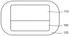
图1a-图1b为根据本发明两个不同实施例的药物输注系统的俯视图;1a-1b are top views of a drug infusion system according to two different embodiments of the present invention;
图2a-图2b为根据本发明一个实施例控制结构的立体结构示意图;2a-2b are three-dimensional schematic diagrams of a control structure according to an embodiment of the present invention;
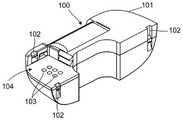
图3a为根据本发明一个实施例输注结构的立体结构示意图;Figure 3a is a schematic three-dimensional structure diagram of an infusion structure according to an embodiment of the present invention;
图3b为根据本发明一个实施例控制结构与输注结构互相装配的侧视图;Figure 3b is a side view of a control structure and an infusion structure assembled with each other according to one embodiment of the present invention;
图3c为根据本发明一个实施例输注结构部分下壳体的俯视结构示意图;3c is a schematic top view of the lower casing of the infusion structure part according to an embodiment of the present invention;
图3d为根据本发明另一个实施例输注结构部分下壳体的俯视结构示意图;3d is a schematic top view of the lower casing of the infusion structure part according to another embodiment of the present invention;
图4a-图4b分别为根据本发明一个实施例输注结构的内部结构两个视角的立体结构示意 图;Figures 4a-4b are respectively three-dimensional schematic diagrams of the internal structure of the infusion structure from two perspectives according to an embodiment of the present invention;
图4c为根据本发明另一个实施例输注结构的内部结构的立体结构示意图;Figure 4c is a three-dimensional schematic view of the internal structure of the infusion structure according to another embodiment of the present invention;
图5为根据本发明实施例的弹性导电体的立体结构示意图;5 is a schematic three-dimensional structural diagram of an elastic conductor according to an embodiment of the present invention;
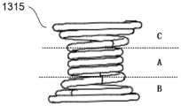
图6为根据本发明实施例的导电弹簧的立体结构示意图;6 is a schematic three-dimensional structural diagram of a conductive spring according to an embodiment of the present invention;
图7为图4a的局部放大图;Fig. 7 is a partial enlarged view of Fig. 4a;
图8a和图8b分别为根据本发明实施例的驱动轮组件与主框架17装配前和装配后的结构 示意图;Fig. 8a and Fig. 8b are respectively the structural schematic diagram before and after the assembly of the drive wheel assembly and the
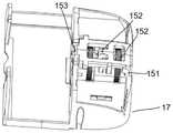
图8c为根据本发明实施例的罩盖的立体结构示意图;8c is a schematic three-dimensional structural diagram of a cover according to an embodiment of the present invention;
图9a-图9d为根据本发明实施例的活动块分别处于打开和闭合状态时的剖面结构示意图 和立体结构示意图;Fig. 9a-Fig. 9d is the sectional structure schematic diagram and the three-dimensional structure schematic diagram when the movable block is respectively in the open and closed state according to the embodiment of the present invention;
图10a-图10c为根据本发明实施例的粘性贴片的结构示意图,各层的结构示意图和层叠 顺序示意图;10a-10c are schematic diagrams of the structure of an adhesive patch according to an embodiment of the present invention, a schematic diagram of the structure of each layer and a schematic diagram of the stacking sequence;
图11a和图2图11b根据本发明另一实施例的控制结构和输注结构的立体结构示意图;Figure 11a and Figure 2 Figure 11b are schematic perspective structures of a control structure and an infusion structure according to another embodiment of the present invention;
图12a为本发明另一实施例在位检测模块包括压变电阻器件的示意图;12a is a schematic diagram of another embodiment of the present invention, the in-situ detection module includes a piezoresistive device;
图12b为本发明另一实施例在位检测模块包括磁性件的示意图;12b is a schematic diagram of another embodiment of the present invention, the presence detection module includes a magnetic component;
图12c为本发明另一实施例在位检测模块包括电感线圈的示意图;12c is a schematic diagram of another embodiment of the present invention, the presence detection module includes an inductor coil;
图12d为本发明另一实施例在位检测模块包括电容下极板的示意图;12d is a schematic diagram of another embodiment of the present invention, the in-situ detection module includes a capacitor lower plate;
图13为正常在位信号阈值区间示意图;FIG. 13 is a schematic diagram of a normal presence signal threshold interval;
图14为根据本发明一个实施例中含有堵塞检测模块的输注结构的内部结构示意图;14 is a schematic diagram of the internal structure of an infusion structure containing a blockage detection module according to an embodiment of the present invention;
图15a为根据本发明一个实施例的输注结构的爆炸图;Figure 15a is an exploded view of an infusion structure according to one embodiment of the present invention;
图15b为根据本发明一个实施例的主框架的结构示意图;15b is a schematic structural diagram of a main frame according to an embodiment of the present invention;
图15c为根据本发明一个实施例的下壳体的结构示意图。FIG. 15c is a schematic structural diagram of a lower casing according to an embodiment of the present invention.
具体实施方式Detailed ways
如前所述,现有技术药物输注装置中供电电源和电路板或立体电路上的特定连接端的电 连接的可靠性较差,影响输注装置的正常使用。As mentioned above, the reliability of the electrical connection between the power supply and the specific connection terminal on the circuit board or the three-dimensional circuit in the prior art drug infusion device is poor, which affects the normal use of the infusion device.
经研究发现,造成上述问题的原因为现有供电电源和电路板或立体电路上的特定连接端 的电连接简单,影响电连接可靠性。Through research, it is found that the reason for the above problem is that the electrical connection between the existing power supply and the specific connection terminal on the circuit board or the three-dimensional circuit is simple, which affects the reliability of the electrical connection.
为了解决该问题,本发明提供了一种药物输注装置,输注结构的弹性导电件上设置有凸 起,可以增强弹性导电体与电源和电路板或立体上的特定连接端的电连接稳定性,提高电连 接的可靠性。In order to solve this problem, the present invention provides a drug infusion device. The elastic conductive member of the infusion structure is provided with protrusions, which can enhance the electrical connection stability between the elastic conductive body and the power supply and the circuit board or the specific connection end on the three-dimensional. , improve the reliability of electrical connection.
现在将参照附图来详细描述本发明的各种示例性实施例。应理解,除非另外具体说明, 否则在这些实施例中阐述的部件和步骤的相对布置、数字表达式和数值不应被理解为对本发 明范围的限制。Various exemplary embodiments of the present invention will now be described in detail with reference to the accompanying drawings. It should be understood that the relative arrangement of components and steps, the numerical expressions and numerical values set forth in these embodiments should not be construed as limiting the scope of the invention unless specifically stated otherwise.
此外,应当理解,为了便于描述,附图中所示出的各个部件的尺寸并不必然按照实际的 比例关系绘制,例如某些单元的厚度、宽度、长度或距离可以相对于其他结构有所放大。In addition, it should be understood that, for the convenience of description, the dimensions of the various components shown in the drawings are not necessarily drawn in an actual proportional relationship, for example, the thickness, width, length or distance of some units may be exaggerated relative to other structures .
以下对示例性实施例的描述仅仅是说明性的,在任何意义上都不作为对本发明及其应用 或使用的任何限制。这里对于相关领域普通技术人员已知的技术、方法和装置可能不作详细 讨论,但在适用这些技术、方法和装置情况下,这些技术、方法和装置应当被视为本说明书 的一部分。The following description of exemplary embodiments is illustrative only and is not intended to limit the invention, its application or uses in any way. Techniques, methods, and apparatuses known to those of ordinary skill in the relevant art may not be discussed in detail here, but where applicable, these techniques, methods, and apparatuses should be considered as part of this specification.
应注意,相似的标号和字母在下面的附图中表示类似项,因此,一旦某一项在一个附图 中被定义或说明,则在随后的附图说明中将不需要对其进行进一步讨论。It should be noted that like numerals and letters refer to like items in the following figures, so once an item is defined or described in one figure, it will not require further discussion in the following figure description .
图1a-图1b为根据本发明两个不同实施例的药物输注装置的俯视图。1a-1b are top views of a drug infusion device according to two different embodiments of the present invention.
本发明实施例的贴片式药物输注装置包括两个部分:控制结构100,输注结构110和粘 性贴片120。下文将分别叙述这些结构。在本发明的其他实施例中,贴片式药物输注装置还 可以包括更多部分,在这里并不作具体限制。The patch-type drug infusion device of the embodiment of the present invention includes two parts: a
贴片式药物输注装置是指不含有长导管的输注装置,并且输注装置由同一片粘性贴片120 被整体粘贴在用户皮肤表面,药物由装置中的输注针单元121直接从储药筒131沿着输注针 输注至皮下。The patch-type drug infusion device refers to an infusion device that does not contain a long catheter, and the infusion device is integrally adhered to the user's skin surface by the same
在本发明实施例中,控制结构100和输注结构110为分体式设计,两者通过防水插塞相 连接或直接卡合并电连接成为一个整体。控制结构100和输注结构110直接卡合并电连接成 为一个整体时可以提高电连接的可靠性,下文将详述。控制结构100可以重复使用,输注结 构110一次性使用后可抛弃,如图1a所示。在本发明另一实施例中,输注结构110和控制 结构100为一体式设计,两者通过导线连接,设置于同一个壳体10的内部,通过粘性贴片 120被粘贴在用户皮肤的某一个位置,一次性使用后整体抛弃,如图1b所示。In the embodiment of the present invention, the
本发明实施例贴片式药物输注装置包括控制结构100。控制结构100用于接收来自远程 设备或者体液参数检测设备(如连续血糖检测设备)的信号或信息,进而控制输注装置完成 药物输注。控制结构100的外壳101内设置有用于接收信号或发出控制指令的程序模块、电 路板和相关电子元器件,以及其他为实现输注功能所必备的物理元器件或结构等,在这里并 不做具体限制。在本发明的一些实施例中,控制结构中还设置有电源。在本发明实施例中, 电源133设置于输注结构110中,如下文所述。The patch-type drug infusion device according to the embodiment of the present invention includes a
图2a-图2b为本发明实施例控制结构100的立体结构示意图。2a-2b are three-dimensional schematic diagrams of the
控制结构100还包括多个暴露于控制结构100表面的第一电触点103。第一电触点103 作为电路连接端,用于将设置于控制结构100与输注结构110的内部电路分别电连接。本发 明实施例对第一电触点103设置的位置不作具体限制。与设置成插接件的连接端相比,电触 点的接触面积更小,可以灵活设计,有效减小控制结构的体积。同时,电触点能够与内部电 路或者电学元件直接电连接,或者可以被直接焊接在电路板上,优化内部电路的设计,有效 降低电路的复杂程度,既节约了成本,又缩小了输注装置的体积。再者,电触点暴露于控制 结构100表面,可便于与其他结构上的连接端之间互相电连接。电触点的以上技术优势适用 于控制结构100上的第一电触点103和输注结构110上的第二电触点113,下文不再详细叙 述。The
第一电触点103的类型包括刚性金属触点或者弹性导电件。优选的,在本发明实施例中, 第一电触点103为刚性金属触点。第一电触点103的一端与设置于控制结构100内部的连接 端电连接,另一端暴露于外壳101表面,第一电触点103的其余部分被紧密嵌入外壳101中, 以实现控制结构100的内部与外界隔绝。Types of first
这里,弹性导电件包括导电弹簧、导电硅胶、导电橡胶或者导电弹片等。明显的,弹性 导电件的一端用于和控制结构100内部的连接端电连接,另一端用于和其他连接端电连接。 如在本发明的一个实施例中,第一电触点103为导电弹簧。当电触点之间互相接触时,导电 弹簧的弹性能够增强电连接的可靠性。与刚性金属触点类似,除了一端部暴露于外壳101表 面,导电弹簧的其他部分紧密嵌入外壳101中,并与内部电路或者电学元件电连接。明显的, 位于控制结构100内部的连接端可以是导电引线,还可以是电路或者电学元件的特定部位。Here, the elastic conductive member includes a conductive spring, a conductive silicone, a conductive rubber, a conductive elastic sheet, and the like. Obviously, one end of the elastic conductive member is used for electrical connection with the connecting terminal inside the
需要说明的是,本发明实施例中的“紧密嵌入”是指电触点与外壳101之间无缝隙,进而 实现对控制结构100内部的密封。下文的“紧密嵌入”与此处的意义相同。It should be noted that, "tightly embedded" in the embodiment of the present invention means that there is no gap between the electrical contact and the
在本发明的另一个实施例中,第一电触点103为导电弹簧,但未紧密嵌入外壳101中, 而是在第一电触点103设置区域的四周设置有密封件,密封件设置于一个凹槽内,以实现对 电连接位置和控制结构100内部的密封。In another embodiment of the present invention, the first
在本发明的实施例中,控制结构100上还设置有第一卡合部102。第一卡合部102用于 和输注结构110的第二卡合部112卡合,实现控制结构100与输注结构110互相装配,进而使第一电触点103与第二电触点113电连接,下文将详细叙述。In the embodiment of the present invention, the
第一卡合部102与第二卡合部112包括能够互相配合卡合的卡勾、卡块、卡孔、卡槽中 的一种或多种,其位置可根据控制结构100与输注结构110的形状结构而灵活设计,如可设 置于对应结构的内部或者表面等位置,在这里并不作具体限制。The first
在本发明实施例中,控制结构100还设置有凹陷104,用于和输注结构110壳体底部的 凸部114互相装配,下文将详细叙述。具体的,第一电触点103设置于凹陷104内,如图2b所示。In the embodiment of the present invention, the
在本发明实施例中,控制结构100内还设置有蜂鸣器(未示出)。在开始或者结束输注、 输注装置发生故障、药物耗尽、控制结构100发出错误指令或者接收到错误信息等状况下, 蜂鸣器用于发出声音、振动等告警信号,以便于用户觉察,并及时调整。In the embodiment of the present invention, a buzzer (not shown) is further provided in the
在本发明实施例中,控制结构100的外壳101上设置有透声孔105,便于传出蜂鸣器的 声音告警信号。为了起到好的密封效果以确保蜂鸣器正常工作,透声孔105与蜂鸣器之间设 置有防水透声膜(未示出)。因此,防水透声膜需要有一定的孔隙率,能够避免水分子进入蜂 鸣器,同时又能够确保将声音传出。In the embodiment of the present invention, the
与传统的将蜂鸣器封闭在控制结构100内部的技术方案相比,设置透声孔105后,蜂鸣 器发出较小的声音即可被用户觉察,降低了蜂鸣器的能耗,优化输注装置的功耗配置,节约 生产成本。Compared with the traditional technical solution of enclosing the buzzer inside the
图3a为本发明实施例输注结构110的立体结构示意图。图3b为本发明实施例控制结构 100与输注结构110互相装配的侧视图。图3c为本发明一个实施例输注结构部分下壳体的俯 视结构示意图。图3d为本发明另一个实施例输注结构部分下壳体的俯视结构示意图。FIG. 3 a is a schematic three-dimensional structural diagram of an
贴片式药物输注装置还包括输注结构110。其壳体内部设置有用于完成药物输注的输注 模块,电路模块和其他辅助模块,下文将详细叙述。输注结构110的壳体可以包括多个部分。 如在本发明实施例中,输注装置的壳体包括上壳体111a与下壳体111b。The patch drug infusion device also includes an
如前文所述,在本发明实施例中,输注结构110设置有第二卡合部112。第二卡合部112 用于和第一卡合部102互相配合卡合。因此,第一卡合部102与第二卡合部112设置的位置 相对应。As mentioned above, in the embodiment of the present invention, the
在本发明实施例中,输注结构110设置有第二电触点113。第二电触点113用于和对应的 第一电触点103互相挤压接触,以实现控制结构100与输注结构110互相电连接。两个不同 结构的电触点之间互相挤压能够提高电连接的可靠性。与第一电触点103相似,第二电触点 113的类型也包括刚性金属触点或者弹性导电件。具体的,在本发明实施例中,第二电触点 113为导电弹簧。同样的,导电弹簧能够提升电连接性能。在设置第二电触点113区域的四 周还设置有凹槽,凹槽中设置有密封件115。In an embodiment of the invention, the
优选的,在本发明实施例中,导电弹簧两端的直径不同,暴露于输注结构110外部的直 径较短,位于输注结构110内部部分的直径较长。较长的直径能够将导电弹簧阻挡在壳体内。 因此,在未将控制结构100安装至输注结构110上时,较长的直径能够避免导电弹簧从输注 结构110上脱落。Preferably, in the embodiment of the present invention, the diameters of the two ends of the conductive spring are different, the diameter exposed to the outside of the
本发明的实施例并不限制第二电触点113设置的位置,只要可以与对应的第一电触点103 互相电连接即可。具体的,在本发明实施例中,输注结构110上壳体111a的底部包括一个凸 部114。第二电触点113设置于凸部114上,如图3a所示。凸部114与控制结构100上的凹 陷104相对应,两者可以互相装配,使第一电触点103和对应的第二电触点113互相挤压, 进而实现电连接。The embodiment of the present invention does not limit the positions where the second
在本发明的其他实施例中,凸部114可以设置于下壳体111b上,或者当输注结构110的 壳体为一个整体时,凸部114为该整体壳体的一部分,在这里并不作具体限制。In other embodiments of the present invention, the protruding
控制结构100与输注结构110互相装配的方式包括沿着输注结构110的厚度方向,将控 制结构100按压在输注结构110上,以使第一卡合部102和第二卡合部112互相卡合。或者 沿着输注结构110的长度方向,将控制结构100按压在输注结构110上。或者是沿着输注结 构110厚度方向与长度方向之间任意角度按压控制结构100,使第一卡合部102和第二卡合 部112互相卡合。优选的,在本发明实施中,控制结构100与输注结构110互相装配的方式为沿着输注结构110的厚度方向,将控制结构100按压在输注结构110上,以使第一卡合部102和第二卡合部112互相卡合,如图3b所示的安装方向。The manner in which the
在本发明实施例中,输注结构110下壳体111b包括向外的延伸部116,且延伸部116的 外侧设置有阻挡块117,如图3a所示。如前文所述,控制结构100沿着输注结构110的厚度方向被按压至卡合位置,阻挡块117能够防止控制结构100沿着输注结构110的长度方向上脱落,确保输注装置正常工作。明显的,在本发明的其他实施例中,如果控制结构100沿着其他方向被按压至卡合位置,通过调整阻挡块117的位置,同样能够防止控制结构100从输注结构110上脱落。In the embodiment of the present invention, the
在这里需要说明的是,“向外”和“外侧”是相对于输注结构110主体部分而言的,属于相 对位置概念,位置关系如图3a或图3b所示。下文的“外侧”与此处的意义相同。It should be noted here that "outward" and "outside" are relative to the main part of the
在本发明实施例中,延伸部116的外侧端部还设置有按压部118,用于解除阻挡块117 的阻挡作用。当用户在更换输注结构110时,手指按压按压部118,即可解除阻挡块117对控 制结构100的阻挡。用户用两个手指将控制结构100从输注结构110上移出。In the embodiment of the present invention, a
本发明实施例还可以设置有解锁孔119。解锁孔119设置于阻挡块117的内侧。在按压按 压部118的同时,食指可以顺势进入解锁孔119,进而将控制结构100顶出,实现控制结构 100从输注结构110上分离。在本发明实施例中,解锁孔119为方形。方形解锁孔119能够便 于手指顺利进入。在本发明的其他实施例中,解锁孔119还可以是其它形状,在这里并不作 具体限制。The embodiment of the present invention may also be provided with an unlocking
输注结构110的下壳体111b上还设置有折痕槽140。折痕槽140设置于解锁孔119的两 侧,如图3c与图3d所示。设置折痕槽140后,折痕槽140位置的下壳体111b的厚度或宽度(如图3c与图3d中箭头所示)被减薄,当用户按压按压部118时,下壳体111b很容易在折 痕槽140处被折断,更加顺利地解除阻挡块117对控制结构100的阻挡。The
优选的,在本发明实施例中,折痕槽140设置于阻挡块117的两端位置,如图3c所示。 在本发明的另一个实施例中,折痕槽140设置于解锁孔119两个对应边的一侧,如图3d所示。Preferably, in the embodiment of the present invention, the
本发明实施例的输注结构110还设置有输注针单元121,用于将药物输注至皮下。The
输注结构110下壳体111b的底部还设置有粘性贴片120,用于将输注装置粘贴在用户皮 肤表面。The bottom of the
图4a-图4b分别为本发明实施例输注结构110的内部结构130两个视角的立体结构示意 图。图4c为根据本发明另一个实施例输注结构110的内部结构130的立体结构示意图。4a-4b are three-dimensional schematic diagrams of the
在本发明实施例中,内部结构130包括用于完成输注功能的机械单元、电控单元等,如 储药筒131、药物出口132、电源133、驱动轮134、螺杆135、电路板(未示出)和驱动单元1310等。驱动单元1310的运动带动驱动轮134转动,进而驱动螺杆135推动储药筒131 中的活塞312(如图14所示)运动,实现药物输注。In the embodiment of the present invention, the
在本发明实施例中,电源133为常规纽扣电池。在本发明的其他实施例中,电源133还 可以是其他类型的电池,只要能够满足向输注装置供电的条件即可。优选的,在本发明实施 例中,电源133为双排电池,即两排电池分别设置于驱动轮134的两侧,如图4b所示。常规 的,纽扣电池的放电能力较低,设置双排纽扣电池能够降低每个电池的放电水平,延长电池 的使用寿命。进一步的,电源133双排设计能够充分利用输注装置内部空间,提高输注装置 内部结构的集成度。In the embodiment of the present invention, the
本发明实施例中的输注结构110内还设置有电路板或者涂覆于部分结构表面的立体电路, 用于向特定的结构单元供电。根据输注装置内部结构特点,立体电路的形状、位置可以被灵 活设计,能够充分利用输注结构内部空间,使得结构更紧凑。电路板为刚性电路板或者柔性 电路板。优选的,在本发明实施例中,电路板为柔性电路板。柔性电路板形状可塑,可根据 输注结构110内部空间灵活设计其形状。同时,柔性电路板上可设置多个连接端与不同的第 二电触点113电连接,从而将控制结构100与输注结构110之间电路导通,使输注装置实现 正常的输注功能。The
输注结构130内部还设置有弹性导电体136。弹性导电体136分别与电源133和电路板 (或者立体电路)上的特定连接端电连接,进而实现对特定结构单元供电。An
图5为根据本发明实施例的弹性导电体136的立体结构示意图。FIG. 5 is a schematic three-dimensional structure diagram of the
在本发明实施例中,弹性导电体136包括与电源133连接的第一弹性导电部136a和与电 路板(或者立体电路)上的特定连接端连接的第二弹性导电部136b,第一弹性导电部136a 和第二弹性导电部136b上均设置有至少一个凸起1361,便于第一弹性导电部136a与电源133 的点接触连接或线接触连接,以及第二弹性导电部136b与电路板(或者立体电路)上的特定 连接端的点接触连接或线接触连接,提高弹性导电片136与电源133和电路板(或者立体电 路)上的特定连接端的电连接可靠性,当弹性导电件136a和第二弹性导电部136b均为平面 时,在使用过程中很可能导致弹性导电体136与电源133和电路板(或者立体电路)上的特 定连接端之间连接接触不良,从而影响使用效果。在本发明实施例中,凸起1361可以是通过 弯折第一弹性导电部136a或第二弹性导电部136b形成的线凸起,也可以是通过其他手段对 第一弹性导电部136a或第二弹性导电部136b进行处理而形成的多个点状或其它形状的凸起, 第一弹性导电部136a或第二弹性导电部136b上凸起1361的形式和数量可以相同,也可以不 同,在这里,凸起1361的形式,数量以及形成方式不作具体限制,只要能加强弹性导电体 136与电源133和电路板(或者立体电路)上的特定连接端的点接触连接或线接触连接,提 高电连接可靠性即可。In the embodiment of the present invention, the elastic
在本发明实施例中,第一弹性导电部136a和第二弹性导电部136b近似成“L”型设置,第 一弹性导电部136a近似平行于主框架137,第二弹性导电部136b近似垂直于主框架137,在 本发明的其他实施例中,第一弹性导电部136a和第二弹性导电部136b还可以设置成其他形 状,在这里并不作具体限制,只要能实现电源133与电路板(或者立体电路)上的特定连接 端电连即可。在第一弹性导电部136a和第二弹性导电部136b的连接处(如图5L处所示) 还设置有绝缘部件1362,防止动力部件1311在工作过程中与弹性导电体136接触造成短路, 使输注结构130停止工作。在本发明实施例中,绝缘部件1362是通过印刷油墨形成的,在本 发明的其他实施例中,绝缘部件1362还可以是绝缘胶,绝缘漆或其绝缘材料,在此不作具体 限制。In the embodiment of the present invention, the first elastic
在本发明实施例中,弹性导电体136可以是包含第一弹性导电部136a和第二弹性导电部 136b金属片体,也可以是由单独的第一弹性导电部136a和第二弹性导电部136b直接或间接 通过其他导电元件电连接而一体化,在此不做限制。当弹性导电体136是包含第一弹性导电 部136a和第二弹性导电部136b金属片体时,不仅弹性导电体136的制造工艺简单,第一弹 性导电部136a和第二弹性导电部136b之间连接牢固,还可以减小弹性导电体138的体积, 节省材料并降低原材料成本和生产成本。当弹性导电体136是第一弹性导电部136a和第二弹 性导电部136b直接或间接通过其他导电元件电连接形成时,可以根据具体连接部件的需求灵 活选择弹性导电部,优化输注结构内部设计。In the embodiment of the present invention, the elastic
在本发明实施例中,主框架137上还设置定位柱138,弹性导电体136上设置有与定位 柱138相适应的开口,弹性导电体136通过开口套设于定位柱138,使弹性导电体136固定于主框架137上,同时采用热熔的方式使定位柱138熔化,进一步固定弹性导电体136,防 止弹性导电体136因为长期的使用或其他原因造成晃动而使弹性导电体136与电源133或电路板(或者立体电路)上的特定连接端之间连接接触不良,影响使用。In the embodiment of the present invention, the
在本发明实施例中,主框架137上还设置有凸台139,凸台139位于第一弹性导电部136a 的下方,防止第一弹性导电部136a的凸起1361在长期使用过程中被压平或变形而导致第一 弹性导电部136a与电路板(或者立体电路)上的特定连接端之间连接接触不良,造成故障。 优选的,凸台139的设置位置偏离凸起1361在主框架137上的投影位置,靠近定位柱138, 一方面可以防止第一弹性导电部136a与电路板(或者立体电路)上的特定连接端之间硬接触 或实压而破坏电路板,另一方面保证第一弹性导电部136a与电路板(或者立体电路)上的特 定连接端之间的弹性电接触。In the embodiment of the present invention, the
与弹性导电件类似,弹性导电体136的类型包括导电弹簧、导电弹片、导电橡胶或者导 电硅胶等,在这里并不作具体限制,只要能够满足将电源133与电路板(或者立体电路)上 特定连接端电连接的条件即可。优选的,在本发明实施例中,弹性导电体136为导电弹片。 明显的,由于输注结构110具有双排电池,因此,弹性导电体136也设计为双排结构,如图 4a所示。Similar to the elastic conductive member, the type of the elastic
弹性导电体136可以实现电源133与特定结构单元直接电连接,减少结构内部的线路设 计,降低了内部结构的复杂程度。The
如图4a所示,输注结构110的内部还包括驱动单元1310和动力部件1311,设置于主框 架137上,主框架137上还设置有转轴1313,驱动单元1310上设置有通孔,驱动单元1310通过通孔套设在转轴1313上进行固定;驱动单元1310包括驱动端1312,动力部件1311一 端与驱动单元1310相连,另一端过导电台1314与电路板或立体电路上特定的电连接端相连,进一步实现与控制结构100内的控制模块相连接。控制结构100内的控制模块对动力部件1311 施加动力,驱动单元1310绕转轴1313转动,带动驱动端1312前进以推动驱动轮134的轮齿 前进,使输注装置进行药物输注。在本发明实施例中驱动端1312为2个,相应的动力部件 1311也为2个。在本发明的另一个实施例中,驱动端1312和动力部件1311分别为1个,如图4c所示。As shown in FIG. 4a, the inside of the
输注结构110的内部还设置有导电塔簧1315,套设于转轴1313,一端抵接驱动单元1310, 另一端与电路板或立体电路上特定电连接端电连接,用于固定驱动单元1310,同时实现驱动 单元1310和电路板或立体电路上特定电连接端之间的电连接。The inside of the
图6根据本发明实施例的导电塔簧1315的立体结构示意图。FIG. 6 is a schematic three-dimensional structural diagram of a
在本发明实施例中,导电塔簧1315包括在轴向方向上呈中心部分直径小的A部分,两 端直径大的B和C部分,其中A部分的直径大小一致,通过过盈配合固定转轴1313,进一步固定驱动单元1310,同时B部分抵接驱动单元1310,防止驱动单元1310因遭受意外的触碰时由于固定不稳而晃动,导致驱动端1312推动驱动轮134前进,影响输注的准确性;B部分和C部分的直径向两端呈喇叭状逐渐扩大,在B部分和C部分分别与驱动单元1310和电 路板或立体电路上的特定电连接端电连接时,导电塔簧1315被压缩,因此B部分和C部分 有多圈,至少有2-3圈弹簧同时与驱动单元1310和电路板或立体电路上的特定电连接端接触,提高输注装置的电连接可靠性。In the embodiment of the present invention, the
优选的,在本发明实施例中,导电塔簧1315的B部分和C部分为对称结构,两端可随意装配,避免出现装配错位。Preferably, in the embodiment of the present invention, the B part and the C part of the
图7为图4a的局部放大图。Fig. 7 is a partial enlarged view of Fig. 4a.
在本发明实施例中,输注结构110内部至少设置有1个导电台1314,具体的,当驱动单 元1310包括2个驱动臂1312时,相应的动力部件1311和导电台均1314为2个,如图4a所示;当驱动单元1310包括1个驱动器1312时,相应的动力部件1311和导电台均为1个,如 图4c所示。导电台1314分别与动力部件1311和电路板或立体电路上的特定连接端电连接。In the embodiment of the present invention, at least one
导电台1314包括导电台本体141和导电臂142,导电臂142为弹性导电元件,导电臂142 上至少设置有一个导电台凸起1421,便于与电路板(或者立体电路)上的特定连接端的点接 触连接或线接触连接,提高导电台1314与电路板(或者立体电路)上的特定连接端的电连接 可靠性,当导电台1314的导电臂为平面结构时,在使用过程中很可能导致导电台1314与电 路板(或者立体电路)上的特定连接端之间连接接触不良,从而影响使用效果。在本发明实 施例中,导电台凸起1421可以是通过弯折导电臂142而形成的线凸起,也可以是通过其他手 段对导电臂142进行处理而形成的多个点状或其它形状的凸起,在这里,导电台凸起1421的 形式,数量以及形成方式不作具体限制,只要能加强导电台1314与电路板(或者立体电路) 上的特定连接端的电连接可靠性即可。在本发明实施例中,导电台本体141还包括导电台本 体端部1411,动力部件1311为电驱动型线性驱动器或电加热型线性驱动器,如形状记忆合 金,通过压铸的方式与导电台本体141相连,连接稳定,电连接可靠性高。具体的,将动力 部件1311放入对折后的导电台本体端部1411中,再通过压铸的方式与导电台本体端部1411 相连,进一步电连接可靠性高。The
在本发明实施例中,导电台1314可以是包含导电台本体141和导电臂142的金属片体, 也可以是导电台本体141和导电臂142直接或间接通过其他导电元件电连接而一体化,在此 不做限制。当导电台1314是包含导电台本体141和导电臂142的金属片体时,不仅可以使导 电台1314的制造工艺简单,导电台本体141和导电臂142之间连接牢固,还可以减小导电台 1314的体积,节省材料并降低原材料成本和生产成本。当导电台1314是导电台本体141和 导电臂142直接或间接通过其他导电元件电连接形成时,可以根据具体连接部件的需求灵活 选择弹性导电部,优化输注结构内部设计。In the embodiment of the present invention, the
同样的,导电台本体141和导电台本体端部1411也可以是金属片体,或直接或间接通过 其他导电元件电连接而一体化,在此不做限制。导电台1314可以为包含导电台本体141,导 电臂142和导电台本体端部1411的金属片体,或是其中两者为金属片体再与第三者直接或间 接通过其他导电元件电连接一体化,或者三者之间都是直接或间接通过其他导电元件电连接 而一体化,在此也不做具体限制。各种成型方式的益处也如前所述,再次不再赘述。优选的, 在本发明实施例中,导电台本体141,导电臂142和导电台本体端部1411三者一体成型。Similarly, the
在本发明实施例中,主框架137上设置有多个挡块1316,用于容纳并限定导电台1314 的位置,主框架137上还设置有导电台定位柱1317,导电台1314上设置有与导电台定位柱 1317相适应的开口,导电台1314通过开口套设于导电台定位柱1317,使导电台1314固定于 主框架137上,同时采用热熔的方式使导电台定位柱1317熔化,进一步固定导电台1314, 防止导电台1314因为长期的使用或其他原因造成晃动而使导电台1314与电路板(或者立体 电路)上的特定连接端之间连接接触不良,影响使用。In the embodiment of the present invention, the
在本发明实施例中,主框架137上还设置有导电台凸台(图中未示出),导电台凸台位于 导电臂142的下方,防止导电臂142的导电台凸起1421在长期使用过程中被压平或变形而导 致导电台141与电路板(或者立体电路)上的特定连接端之间连接接触不良,造成故障。优 选的,导电台凸台的设置位置偏离导电台凸起1421在主框架137上的投影位置,靠近导电台 定位柱1317,一方面可以防止导电臂142与电路板(或者立体电路)上的特定连接端之间硬 接触或实压而破坏电路板,另一方面保证导电臂142与电路板(或者立体电路)上的特定连 接端之间的弹性电接触。In the embodiment of the present invention, the
与弹性导电体136类似,导电台1314的类型包括导电弹簧、导电弹片、导电橡胶或者导 电硅胶等,在这里并不作具体限制,只要能够满足将动力部件1310与电路板(或者立体电路) 上特定连接端电连接的条件即可。Similar to the
图8a和图8b分别为根据本发明实施例的驱动轮组件与主框架17装配前和装配后的结构 示意图。图8c为根据本发明实施例的罩盖的立体结构示意图。Fig. 8a and Fig. 8b are respectively schematic structural diagrams of the drive wheel assembly before and after the assembly of the
驱动轮组件包括驱动轮本体16和活动块18。驱动轮本体16包括驱动轮161,驱动管162, 内设有螺纹,用于容纳螺杆135,以及设置于驱动轮161端部的连接件163,连接件163上设 置有连接部1631,用于与活动块18可操作性连接。活动块18内设置有螺纹,用于容纳螺杆 135,活动块18上还设置有与连接部1631进行活动连接的活动块连接杆181,连接杆181与 连接部1631活动连接后,活动块18可绕连接杆181进行转动,从而打开或闭合活动块18。 活动块18打开时,螺杆135可向驱动轮本体16侧滑动,活动块18闭合时,螺杆135不能向驱动轮本体16侧滑动,下文将详述。The drive wheel assembly includes a
驱动轮组件还包括罩盖15,罩盖15上设置有多个罩盖卡合部151,用于与主框架17卡 合。主框架17上设置有主框架凹槽171,用于容纳驱动轮本体16,还设置有多个与罩盖卡合 部151进行卡合的主框架卡合部172。将驱动轮本体16和活动块18连接之后放入主框架凹 槽171中,再将罩盖15装配到主框架17,通过主框架卡合部173和罩盖卡合部151的卡合,可使驱动轮本体16和活动块18固定在主框架17中,防止驱动轮本体16的晃动而影响药物输注的准确性。The driving wheel assembly further includes a
主框架卡合部172和罩盖卡合部151包括能够互相配合卡合的卡勾、卡块、卡孔、卡槽 中的一种或多种,其位置可根据主框架17与罩盖15的形状结构而灵活设计,在这里并不作 具体限制。优选的,多个主框架卡合部173和多个罩盖卡合部151形成的结构主体可以正好 容纳驱动轮本体16和活动块18,防止驱动轮本体16的晃动。The main
在本发明实施例中,罩盖15还设置有至少一个弹性臂152,用于弹性抵接驱动管162, 可进一步固定驱动轮本体16,提高输注结构110的稳定性以及药物输注的准确性。优选的, 弹性臂152为2个,分列在其中一个驱动轮161的两侧,分别抵接驱动管162,如图8b所示, 多点固定驱动轮本体16。In the embodiment of the present invention, the
罩盖15还设置有挡片153,挡片153上设置有拗口,主框架17靠近储药筒131的侧边上还设置有卡槽173,用于容纳档条(图中未示出),档条与挡片153抵接形成通孔,用于容纳螺杆135,同时将驱动轮本体16和活动块18限定在主框架17中。优选的,挡片153的拗 口为半圆形,直径与螺杆135直径相适应,更好的容纳螺杆135,防止螺杆135在外力作用 下发生较大幅度的晃动。The
优选的,在本发明实施例中,罩盖为一体成型结构,工艺简单,体积小,连接牢固,节 省材料,降低成本。Preferably, in the embodiment of the present invention, the cover is an integral molding structure, the process is simple, the volume is small, the connection is firm, the material is saved, and the cost is reduced.
图9a-图9d是根据本发明实施例的活动块18分别处于打开和闭合状态时的剖面结构示意 图和立体结构示意图。9a-9d are schematic cross-sectional structural diagrams and three-dimensional structural diagrams of the
活动块18还包括上活动块182和下活动块183,下活动块183还设置有下活动块端部1831。 活动块18打开是指上活动块182靠近驱动轮161,下活动块183远离驱动轮161,活动块18 内的螺纹与螺杆135不咬合,螺杆135可以在活动块18和驱动管162中顺利的滑动。活动块 18闭合是指上活动块182远离驱动轮161,下活动块183靠近驱动轮161,此时,活动块18 内的螺纹与螺杆135咬合,螺杆135无法在活动块18和驱动管162中滑动。The
在本发明实施例中,主框架17上还设置有弧形阻挡件174,用于限定下活动块183的位 置。当活动块18打开即上活动块182靠近驱动轮161,下活动块183远离驱动轮161时,下 活动块183的下活动块端部1831位于弧形阻挡件174的外侧,使活动块183保持在打开状态。 此时,活动块18内的螺纹与螺杆135不咬合,螺杆135可以在活动块18和驱动管162中顺利的滑动,活动块18处于打开状态时,可以向储药筒131灌药,在向储药筒131灌药的过程中,螺杆135在灌药过程中产生的推动作用下就可以顺利的向驱动轮161端移动,直至完成灌药,而不需要其他部件的协助,结构简单,集成度高,节省成本,减小输注结构110的体积,同时最大限度的利用储药筒131的实际储药空间。In the embodiment of the present invention, the
当活动块18闭合即活动块182远离驱动轮161,下活动块183靠近驱动轮161时,下活 动块183的下活动块端部1831位于弧形阻挡件174的内侧,活动块18保持在闭合状态。此时,活动块18内的螺纹与螺杆135咬合,螺杆135无法在活动块18和驱动管162中滑动, 当灌药结束后,输注装置110实施药物输注时,驱动单元1310的驱动端1312推动驱动轮161 前进,活动块18随着驱动轮161转动,转动过程中,下活动块端部1831绕过弧形阻挡件174 后,由于不再有弧形阻挡件174的阻挡,下活动块端部1831落入到弧形阻挡件174的内侧, 同时由于活动块18保持在闭合状态,螺杆135只能在驱动轮161的转动而产生的推动作用下 向远离驱动轮161的方向移动,进行药物输注,而不用担心由于螺杆135与活动块18或驱动 管162内的螺纹咬合失效而导致螺杆135自由移动,影响输注效果甚至是造成输注装置失效。When the
在本发明实施例中,靠近储药筒131的驱动轮16的端面设置有凹口1611,形状与下活 动块183相适应,用于容纳下活动块183。当下活动块端部1831绕过弧形阻挡件174,落入到弧形阻挡件174的内侧时,下活动块183容纳在驱动轮161的凹口1611中,充分利用驱动轮本体的空间,优化输注结构内部设计,减小输注装置的体积。In the embodiment of the present invention, a
在这里需要说明的是,“内侧”和“外侧”是相对于弧形阻挡件174而言的,属于相对位置 概念,位置关系如图9b或图9d所示。It should be noted here that "inside" and "outside" are relative to the arc-shaped blocking
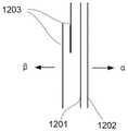
图10a是本发明实施例中粘性贴片120的结构示意图。图10b为粘性贴片120各层的结 构示意图,图10c为粘性贴片120的层叠顺序示意图。FIG. 10a is a schematic structural diagram of an
粘性贴片120包括胶布1201,胶布1201的第一面α面与输注结构110的下壳体110b固 定连接,第二面β面上涂覆有粘贴材料,用于将输注装置粘贴在宿主皮肤表面。胶布1201选 用聚乙烯、聚丙烯、无纺布或纯棉中的一种,胶布1201与宿主皮肤直接接触,根据实际使用 环境,选用上述材料可以避免胶布1201长时间与皮肤接触造成的不良反应。为了适应宿主皮 肤的运动,如曲折、拉伸等,胶布1201的厚度很薄,例如约为0.001um~1um。这样薄的胶布 会产生其他的问题,如宿主皮肤的静电,在安装到皮肤表面前,皮肤的静电使胶布发生卷边 或者翘边,使其不能平铺在皮肤表面,或者在安装到皮肤表面后,由于皮肤的剧烈运动,会 使胶布的边缘发生卷边或者翘边。一旦胶布边缘发生卷边或者翘边,随着使用时间的增加, 胶布1201卷边或者翘边的面积会逐渐增加,导致胶布1201与皮肤间的粘贴力减小,从而可 能导致输注装置发生位移或者脱落,影响用户体验。The
胶布1201的第一面α面的外沿增设保护膜1202,保护膜1202的洛氏硬度大于胶布1201, 在本发明优选实施例中,保护膜1202的洛氏硬度为80~100HRM。A
在本发明优选实施例中,保护膜1202为聚碳酸酯、聚酰胺、聚甲醛、聚苯醚、聚酯、聚 苯硫醚、聚芳基酯中的一种。In a preferred embodiment of the present invention, the
在本发明更优选实施例中,保护膜1202为聚对苯二甲酸乙二醇酯(PET),其洛氏硬度 为90~95HRM。In a more preferred embodiment of the present invention, the
保护膜1202的外沿轮廓与胶布1201的外沿轮廓相适应,这里相适应是指保护膜1202的 外沿轮廓尺寸、弯折半径、形状等参数均与胶布1201的外沿轮廓参数一致,使得胶布1201 外沿的每一处均能与保护膜1202贴合。The outer contour of the
在本发明优选实施例中,保护膜的厚度为0.01~100um。In a preferred embodiment of the present invention, the thickness of the protective film is 0.01-100um.
在本发明再一个优选实施例中,保护膜1202为环状结构,环状结构的中空构造可以使得 保护膜贴合在胶布1201的第一面α面,而不与输注装置发生干涉,其次环状结构的保护膜内 沿与外沿轮廓相一致,更为美观,增强了用户体验。In yet another preferred embodiment of the present invention, the
在本发明实施例中,胶布1201上开设有第一通孔12011,第一通孔12011的位置对应于 输注针121刺入体内的部分,如图10b所示,用于使输注针121穿过以刺入宿主皮肤。In the embodiment of the present invention, the
在胶布1201的第二面β面上还设置有至少一层离型纸1203,离型纸1203可以防止胶布 1201的第二面β面上的粘贴材料粘连,又可以保护粘贴材料不受污染。At least one layer of
在本发明优选实施例中,离型纸1203为单硅离型纸,其剥离力为30~50g。In a preferred embodiment of the present invention, the
在本发明实施例中,离型纸1203上开设有第二通孔12031,第二通孔12031的位置对应 于第一通孔12011,使得输注针121可以依次通过第一通孔12011和第二通孔12031,以刺入 宿主皮肤。In the embodiment of the present invention, the
为便于用户剥离离型纸1203与胶布1201,并且节省空间,离型纸1203优选为两层,其 剥离口彼此相对向内,其中一层的剥离口向外弯折,并被另一层的剥离口覆盖。结合前文所 述,粘性贴片120自α面向β面依次为保护膜1202、胶布1201和离型纸1203。In order to facilitate the user to peel off the
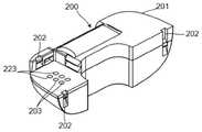
图11a和图11b根据本发明另一实施例的控制结构200和输注结构210的立体结构示意 图。Figures 11a and 11b are schematic three-dimensional structural diagrams of a
在本发明实施例中,控制结构200和输注结构210与前述实施例中的控制结构100和输 注结构110(如图2和图3所示)的主要结构差别在于控制结构200包括第一电接触点203 和第一物理部件223,输注结构210包括第二电接触点213和在位检测模块222,下文将详述, 其他结构与前述控制结构100和输注结构110一致,在此将不再赘述。In this embodiment of the present invention, the main structural difference between the
第二电接触点213和在位检测模块222,均设置于输注结构210的上壳体211a的凸台214 上,可以充分利用输注装置的内部空间,优化电路板或立体电路的电路结构设置。在其他发 明实施例中,第二电接触点213和在位检测模块222也可以设置在输注结构210的其他位置, 在此不做限定。The second
在位检测模块222包括第二物理部件2221,如压变电阻器件、磁性件、电感线圈、电容 等,本领域技术人员可以理解的是,上述物理部件也可以组合使用,并且在位检测模块223 可使用的物理部件不限于此,其他可触发位置信号的物理部件均可用在此处。第一物理部件 223与第二物理部件2221可操作性电连接,这里“可操作性”电连接是指,根据第一物理部件 223和第二物理部件2221的种类,其具有不同的电连接方式。The
图12a为本发明另一实施例在位检测模块包括压变电阻器件的示意图。12a is a schematic diagram of another embodiment of the present invention, the in-situ detection module includes a piezoresistive device.
在本发明实施例中,在位检测模块222的第二物理部件2221为压变电阻器件,压变电阻 器件对压力敏感,外部器件对压变电阻器件的压力变化可引起压变电阻器件的电阻值变化, 该变化可以是线性的,也可以是非线性的。利用该原理可检测控制结构200与输注结构210 结合的牢固程度。In the embodiment of the present invention, the second
第二物理部件2221为压变电阻器件,位于输注结构210的凸部214上,对应的,控制结 构上的第一物理部件223为刚性电接触点。控制结构安装到输注结构上时,刚性电接触点与 压变电阻器件接触,本领域技术人员可以知晓的是,为了形成闭环电路,刚性电接触点数量 为两个,即第一刚性电接触点223a和第二刚性电接触点223b。The second
在本发明实施例中,控制结构与输注结构正常连接时,刚性电接触点与压变电阻器件接 触产生基础压力F1,对应基础压力,压变电阻器件产生基础电阻R1。当控制结构与输注结 构的连接变松而失位时,刚性电接触点与压变电阻器件接触产生的压力变小,例如变为F2, 显然F2<F1,相应的压变电阻器件电阻值变为R2,若压变电阻器件为正反馈器件,则R2<R1,反之,若压变电阻器件为负反馈器件,则R2>R1。当控制结构与输注结构的连接变紧 时,刚性电接触点与压变电阻器件接触产生的压力变大,例如变为F3,显然F3>F1,相应 的压变电阻器件电阻值变为R3,若压变电阻器件为正反馈器件,则R3>R1,反之,若压变电阻器件为负反馈器件,则R3<R1。In the embodiment of the present invention, when the control structure and the infusion structure are normally connected, the rigid electrical contact point is in contact with the piezoresistive device to generate a base pressure F1, corresponding to the base pressure, the piezoresistive device generates a base resistance R1. When the connection between the control structure and the infusion structure becomes loose and out of position, the pressure generated by the contact between the rigid electrical contact point and the piezoresistive device becomes smaller, for example, it becomes F2, obviously F2<F1, and the corresponding resistance value of the piezoresistive device It becomes R2, if the piezoresistive device is a positive feedback device, then R2<R1, on the contrary, if the piezoresistive device is a negative feedback device, then R2>R1. When the connection between the control structure and the infusion structure becomes tight, the pressure generated by the contact between the rigid electrical contact point and the piezoresistive device becomes larger, for example, it becomes F3, obviously F3>F1, and the corresponding resistance value of the piezoresistive device becomes R3 , if the piezoresistive device is a positive feedback device, then R3>R1, on the contrary, if the piezoresistive device is a negative feedback device, then R3<R1.
无论压变电阻器件为正反馈器件或是负反馈器件,其电阻值与其受到的压力存在唯一对 应关系,而其受到的压力与控制结构和输注结构结合的牢固程度呈正相关关系,因此压变电 阻器件的电阻值间接表征了控制结构和输注结构结合的牢固程度。Regardless of whether the piezoresistive device is a positive feedback device or a negative feedback device, its resistance value has a unique corresponding relationship with the pressure it receives, and the pressure it receives has a positive correlation with the firmness of the combination of the control structure and the infusion structure. The resistance value of the resistive device indirectly characterizes the firmness of the binding between the control structure and the infusion structure.
在本发明优选实施例中,压变电阻器件的电阻值R经过相关算法运算后,转换为控制结 构与输注结构的相对位置数据,再由控制结构无线传输至远程设备,如PDM(PersonalDiabetes Manager),移动终端等,便于用户实时了解控制结构的安装松紧程度。In a preferred embodiment of the present invention, the resistance value R of the piezoresistive device is converted into the relative position data of the control structure and the infusion structure after the relevant algorithm operation, and then wirelessly transmitted from the control structure to a remote device, such as PDM (Personal Diabetes Manager). ), mobile terminals, etc., so that users can know the installation tightness of the control structure in real time.
在本发明优选实施例中,压变电阻器件为压变电阻导电胶条,压变电阻导电胶条容易切 割,可被加工成任意形状,以适应检测装置的结构设计要求。In a preferred embodiment of the present invention, the piezoresistive device is a piezoresistive conductive rubber strip, which is easy to cut and can be processed into any shape to meet the structural design requirements of the detection device.
图12b为本发明另一实施例在位检测模块包括磁性件的示意图。12b is a schematic diagram of another embodiment of the present invention, the presence detection module includes a magnetic component.
在本发明实施例中,在位检测模块的第二物理部件3221为磁性件,磁性件提供稳定磁场。 在不同的有效距离上,磁性件有不同的磁场方向和磁场强度。利用该原理可检测控制结构与 输注结构结合的牢固程度。In this embodiment of the present invention, the second
第二物理部件3221为磁性件,对应的,输注结构上的第一物理部件323为磁感元件。控 制结构安装到输注结构上时,磁感元件感应磁性件的磁场方向或者磁场强度,或者同时感应 磁性件的磁场方向和磁场强度。磁感元件与磁性件间的距离O不同,所感应到的磁场方向或 者磁场强度也不同。优选的,磁感元件感应磁性件的磁场强度H。The second
在本发明实施例中,输注结构与控制结构正常连接时,磁感元件与磁性件间的距离为O1, 磁感元件感应到磁性件的基础磁场强度H1。当输注结构与控制结构的连接变松而失位时,磁 感元件与磁性件间的距离变大,例如变为O2,O2>O1,相应的磁感元件感应到磁性件的磁 场强度变为H2,显然H2<H1。当输注结构与控制结构的连接变紧时,磁感元件与磁性件间 的距离变小,例如变为O3,O3<O1,相应的磁感元件感应到磁性件的磁场强度变为H3,显 然H3>H1。In the embodiment of the present invention, when the infusion structure and the control structure are normally connected, the distance between the magnetic induction element and the magnetic element is O1, and the magnetic induction element senses the basic magnetic field strength H1 of the magnetic element. When the connection between the infusion structure and the control structure becomes loose and becomes out of position, the distance between the magnetic induction element and the magnetic element becomes larger, for example, it becomes O2, O2>O1, and the corresponding magnetic induction element senses that the magnetic field strength of the magnetic element changes. is H2, obviously H2<H1. When the connection between the infusion structure and the control structure is tightened, the distance between the magnetic induction element and the magnetic piece becomes smaller, for example, it becomes O3, O3 < O1, and the magnetic field intensity of the magnetic induction element sensed by the corresponding magnetic piece becomes H3, Obviously H3>H1.
无论磁感元件与磁性件间的距离O如何变化,距离O与磁场强度H之间存在唯一对应 关系,而磁感元件与磁性件间的距离和输注结构与控制结构结合的牢固程度相关,因此磁感 元件感应的磁性件磁场强度H间接表征了输注结构和控制结构结合的牢固程度。No matter how the distance O between the magnetic induction element and the magnetic piece changes, there is a unique correspondence between the distance O and the magnetic field strength H, and the distance between the magnetic induction element and the magnetic piece is related to the firmness of the combination of the infusion structure and the control structure. Therefore, the magnetic field strength H of the magnetic element induced by the magnetic induction element indirectly represents the firmness of the combination of the infusion structure and the control structure.
在本发明优选实施例中,磁感元件感应的磁性件磁场强度H经过相关算法运算后,转换 为输注结构与控制结构的相对位置数据,再由控制结构200无线传输至远程设备,如PDM(Personal Diabetes Manager),移动终端等,便于用户实时了解输注结构和控制结构的安 装松紧程度。In a preferred embodiment of the present invention, the magnetic field strength H of the magnetic element induced by the magnetic induction element is converted into the relative position data of the infusion structure and the control structure after the relevant algorithm operation, and then wirelessly transmitted by the
图12c为本发明另一实施例在位检测模块包括电感线圈的示意图。FIG. 12c is a schematic diagram of an in-position detection module including an inductor coil according to another embodiment of the present invention.
在本发明实施例中,在位检测模块的第二物理部件4221为电感线圈,电感线圈的电感值 L可由以下公式计算得到:In this embodiment of the present invention, the second physical component 4221 of the presence detection module is an inductance coil, and the inductance value L of the inductance coil can be calculated by the following formula:

式中,In the formula,
D为电感线圈直径;D is the diameter of the inductor coil;
l为电感线圈长度;l is the length of the inductor coil;
N为电感线圈匝数。N is the number of turns of the inductor coil.
对于同一电感线圈,其直径D和匝数N不会再有变化,而其长度l可以随着两端的挤压 力或者拉伸力而发生改变,当其长度l发生改变时,其电感值L也会发生变化。利用该原理 可检测输注结构与控制结构结合的牢固程度。For the same inductive coil, its diameter D and number of turns N will not change, and its length l can change with the extrusion force or tensile force at both ends. When its length l changes, its inductance value L will also change. Using this principle, the firmness of the combination of the infusion structure and the control structure can be detected.
第二物理部件4221包括电感线圈4221a和导电凸台4221b,导电凸台4221b位于凸台411 上,电感线圈4221a与导电凸台4221b电连接。对应的,输注结构上的第一物理部件423包 括与电感线圈一端接触的按压件423a和通过导电凸台3142b与电感线圈另一端电连接的弹性 电接触点423b。本领域技术人员可以知晓的是,为了获取电感线圈的电感值L,导电凸台4221b、 按压件423a及弹性电接触点423b均为导电材料。The second physical component 4221 includes an
在本发明实施例中,输注结构与控制结构正常连接时,按压件423a接触电感线圈的一端, 弹性电接触点423b接触电感线圈的另一端,按压件423a、电感线圈、弹性电接触点423b形 成闭合电路,输注结构内的内部电路可以获取电感线圈的电感值L,此时输注结构与控制结 构的距离为s1,电感线圈的长度为l1,对应于该电感线圈长度,电感线圈的基础电感值为L1。 当输注结构与控制结构的连接变松而失位时,输注结构与控制结构的距离变为s2,按压件423a 随输注结构运动,电感线圈的长度变为l2,s2>s1,l2>l1,此时电感线圈的电感值变为L2, 显然L2<L1。当输注结构与控制结构的连接变紧时,输注结构与控制结构的距离变为s3,按 压件423a随输注结构运动,电感线圈的长度变为l3,s3<s1,l3>l1,此时电感线圈的电感 值变为L3,显然L3>L1。无论输注结构与控制结构间的距离如何变化,由于弹性电触点423b 为弹性材料,因此弹性电触点423b可以与电感线圈保持良好的电接触,除非输注结构完全脱 离控制结构。In the embodiment of the present invention, when the infusion structure is normally connected to the control structure, the pressing
无论电感线圈的长度l如何变化,长度l与电感值L之间存在唯一对应关系,而电感线 圈的长度l和输注结构与控制结构结合的牢固程度相关,因此电感线圈的电感值L间接表征 了输注结构和控制结构结合的牢固程度。No matter how the length l of the inductive coil changes, there is a unique correspondence between the length l and the inductance value L, and the length l of the inductive coil is related to the firmness of the combination of the infusion structure and the control structure, so the inductance value L of the inductive coil indirectly represents the The firmness of the combination of the infusion structure and the control structure.
在本发明优选实施例中,电感线圈的电感值L经过相关算法运算后,转换为输注结构与 控制结构的相对位置数据,再由控制结构200无线传输至远程设备,如PDM(PersonalDiabetes Manager),移动终端等,便于用户实时了解输注结构的安装松紧程度。In a preferred embodiment of the present invention, the inductance value L of the inductance coil is converted into the relative position data of the infusion structure and the control structure after the relevant algorithm operation, and then wirelessly transmitted by the
图12d为本发明另一实施例在位检测模块包括电容下极板的示意图。FIG. 12d is a schematic diagram of an in-position detection module including a capacitor lower plate according to another embodiment of the present invention.
在本发明实施例中,在位检测模块的第二物理部件5221包括电容的下极板,对应的,第 一物理部件523包括电容的上极板523a和弹性电触点523b,上极板523a与下极板组合为完 整的电容,弹性电触点523b用于与下极板电接触,组成闭合电路,输注结构中的内部电路可 以测量电容的电容值C。电容的电容值C由一下公式可以确定:In the embodiment of the present invention, the second

式中:ε为常数;In the formula: ε is a constant;
S为电容上下极板的正对面积;S is the area facing the upper and lower plates of the capacitor;
k为静电力常数;k is the electrostatic force constant;
d为电容上下极板间的距离。d is the distance between the upper and lower plates of the capacitor.
对于由上下极板组成的电容,其正对面积S和静电力常数ε为定值,不会再有变化,而其 上下极板间的距离d可以随输注结构和控制结构结合的牢固程度发生变化,当其距离d发生 变化时,其电容值C也会发生变化。利用该原理可检测输注结构与控制结构结合的牢固程度。For the capacitor composed of upper and lower pole plates, its facing area S and electrostatic force constant ε are constant and will not change, and the distance d between the upper and lower pole plates can vary with the firmness of the combination of the infusion structure and the control structure. When the distance d changes, its capacitance value C also changes. Using this principle, the firmness of the combination of the infusion structure and the control structure can be detected.
如前所述,第一物理部件523包括电容的上极板523a和弹性电触点523b,上极板523a 与下极板组合为完整的电容,弹性电触点523b用于与下极板电接触,组成闭合电路。本领域 技术人员可以知晓的是,为了获取电容值,弹性电触点523b为导电材料。As mentioned above, the first physical component 523 includes the
在本发明实施例中,输注结构与控制结构正常连接时,上极板523a与下极板组成电容, 弹性电触点523b与下极板接触,用于为下极板提供与上极板523a相反的电荷,此时上极板 523a与下极板的距离为d1,对应于该上下极板距离,电容的电容值为C1。当输注结构与控 制结构的连接变松而失位时,输注结构与控制结构的距离变为d2,d2>d1,此时电容的电容 值变为C2,显然C2<C1。当输注结构与控制结构的连接变紧时,输注结构与控制结构的距 离变为d3,d3<d1,此时电容的电容值变为C3,显然C3>C1。无论输注结构与控制结构间 的距离如何变化,由于弹性电触点523b为弹性材料,因此弹性电触点523b可以与电感线圈 保持良好的电接触,除非输注结构完全脱离控制结构。In the embodiment of the present invention, when the infusion structure and the control structure are normally connected, the
无论电容上下极板间的距离d如何变化,距离d与电容值C之间存在唯一对应关系,而 上下极板间的距离d和输注结构与控制结构结合的牢固程度相关,因此电容的电容值C间接 表征了输注结构和控制结构结合的牢固程度。No matter how the distance d between the upper and lower plates of the capacitor changes, there is a unique correspondence between the distance d and the capacitance value C, and the distance d between the upper and lower plates is related to the firmness of the combination of the infusion structure and the control structure, so the capacitance of the capacitor The value C indirectly characterizes the firmness of the binding of the infusion structure and the control structure.
在本发明优选实施例中,电容的电容值经过相关算法运算后,转换为输注结构与控制结 构的相对位置数据,再由控制结构200无线传输至远程设备,如PDM(PersonalDiabetes Manager),移动终端等,便于用户实时了解输注结构的安装松紧程度。In a preferred embodiment of the present invention, the capacitance value of the capacitor is converted into the relative position data of the infusion structure and the control structure after the relevant algorithm operation, and then wirelessly transmitted by the
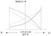
在上述实施例中,控制结构200的内部电路还设置有控制结构正常在位的信号阈值区间。 图13为正常在位信号阈值区间示意图。在位检测模块可能为压变电阻器件、电感线圈、磁性 件或电容中的一种或者多种组合,其参数信号和输注结构与控制结构结合的牢固程度可能呈 线性关系,也可能呈非线性关系,可能是正反馈关系,也可能是负反馈关系。无论是何种关 系,参数信号和输注结构与控制结构间结合的牢固程度是唯一对应的,因此参数信号存在唯 一的最大阈值和唯一的最小阈值,上述最大阈值和最小阈值之间的区间为正常在位阈值区间, 在该区间内,控制结构正常地固定在输注结构上。In the above embodiment, the internal circuit of the
若参数信号超出正常在位阈值区间,即表征控制结构已松脱,或者控制结构因外界挤压 而与输注结构结合过紧,此时控制结构的内部电路发出报警信号,提示用户按压控制结构, 或者更换输注结构,或者取消外界压力。If the parameter signal exceeds the normal in-position threshold range, it means that the control structure has been loosened, or the control structure has been tightly combined with the infusion structure due to external extrusion. At this time, the internal circuit of the control structure will issue an alarm signal, prompting the user to press the control structure. , or replace the infusion structure, or cancel the external pressure.
为适应不同用户的需求,报警信号的表现形式可被设计为发光信号、振动信号、声音信 号中的一种或者多种组合。In order to meet the needs of different users, the manifestation of the alarm signal can be designed as one or a combination of light signals, vibration signals, and sound signals.
图14为根据本发明一个实施例中含有堵塞检测模块的输注结构的内部结构示意图。FIG. 14 is a schematic diagram of the internal structure of an infusion structure containing a blockage detection module according to an embodiment of the present invention.
在本发明实施例中,输注装置中还设置有堵塞检测模块,与控制结构可操作性连接,用 于在灌药过程中或药物输注过程中感知并测量相关物理参数来确认是否发生堵塞。堵塞检测 模块包括检测电路(图中未示出)和至少一个检测元件311。检测电路设置于控制结构中, 检测元件311设置于输注结构310中。检测电路与至少一个检测元件311协作以提供为了堵 塞检测的目的而需要分析和处理的相应的信号,数据或信息等。检测电路中还存储有预设的 各相关物理参数的阈值,以及将感测的相关物理参数与预设的阈值进行比较的比较器,当感 测的相关物理参数大于或小于相应的预设的阈值时,检测电路发出报警信号,提醒用户发生 堵塞,停止输注并更换输注结构或进行其他操作,以免造成安全隐患。In the embodiment of the present invention, the infusion device is further provided with a blockage detection module, which is operably connected to the control structure and is used to sense and measure relevant physical parameters to confirm whether blockage occurs during the drug filling process or the drug infusion process. . The blockage detection module includes a detection circuit (not shown in the figure) and at least one
在本发明的一个实施例中,检测元件311为输注装置本身的部件,动力部件313,优选 的,动力部件313为电驱动型线性驱动器或电加热型线性驱动器,如形状记忆合金,检测电 路中设置有计时器,用于记录动力部件313拉动驱动端314而推动驱动轮315转动,进而推 动活塞312前进一个步长所用的时间,当活塞312前进一个步长的时间大于某一预设的阈值 时,检测电路发出报警信号,提醒用户发生堵塞。在本发明实施例中,动力部件为输注装置 本身的部件,利用该部件作为检测元件,可以优化输注装置内部结构设置,降低成本。In one embodiment of the present invention, the
在本发明的其他发明实施例中,检测元件311为非输注装置本身的部件,如力传感器, 加速度传感器,位置检测元件中的一种或多种。如图14所示,检测元件311设置于储活塞 312中,在本发明的其他实施例中,检测元件311还可以设置在输注结构310的其他部件中, 如螺杆316,螺杆316与活塞312的连接处等的一处或多处,在此不作限定,可以根据实际 构造进行灵活设置,优化输注结构的内部设计。In other inventive embodiments of the present invention, the
在本发明的另一个实施例中,检测元件311为力传感器,具体的,力传感器为拉力传感 器,在药物灌入或输注的过程中,拉力传感器用于感测动力部件313作用于螺杆316或活塞 312上的力的大小,当感测到的力大于某一预设的阈值时,检测电路发出报警信号,提醒用 户发生堵塞。In another embodiment of the present invention, the
在本发明的一个实施例中,检测元件311为力传感器,具体的,力传感器为压力传感器, 在药物灌入或输注的过程中,压力传感器感知并测量活塞施加到药物的压力的大小,当感测 到的压力大于某一预设的阈值时,检测电路发出报警信号,提醒用户发生堵塞。In one embodiment of the present invention, the
在本发明的另一个实施例中,检测元件311为加速度传感器,在药物灌入或输注的过程 中,加速度传感器可以感知并测量螺杆315或活塞312在储药筒313中移动的速度或加速度, 检测电路将其转化为单位时间内的速度和加速度的变化值,当检测到的该变化值小于某一预 设的阈值时,检测电路发出报警信号,提醒用户发生堵塞。In another embodiment of the present invention, the
在本发明的另一个实施例中,检测元件311为位置检测元件,在药物灌入或输注的过程 中,通过位置检测元件检测活塞312或螺杆136端部在储药筒317中的轴向(沿螺杆136移 动的方向)位置变化,检测电路将活塞312或螺杆136端部在单位时间内的轴向位置信息转 化活塞312或螺杆136端部在储药筒317中移动的速度或加速度,进一步计算活塞312或螺 杆136端部移动的速度或加速度的变化值,当该变化值小于某一预设的阈值时,检测电路发 出报警信号,提醒用户发生堵塞。In another embodiment of the present invention, the
优选的,在本发明实施例中,位置检测元件通过非接触式的检测方式检测活塞312或螺 杆136端部的位置,位置检测元件为磁性元件,用于提供磁场,检测电路中设置有磁感元件, 磁感元件感应的磁场强度会随着磁性元件,即活塞312或螺杆136端部的位置变化而改变, 因此,通过感应的磁场变化,检测电路可以计算出活塞312或螺杆136端部的位置变化,如 前所述,进一步检测是否发生堵塞。Preferably, in the embodiment of the present invention, the position detection element detects the position of the end of the
优选的,在本发明实施例中,检测元件311设置在活塞312中,活塞312中设置有至少 一个凹部3121,用于容纳检测元件311,凹部3121内侧还设置有多个凸出部3122,用于固定检测元件311,凹部3121中间还设置有定位部3123,进一步固定检测元件311,防止检测元件311晃动而造成感测信息出现偏差而影响检测结果。Preferably, in the embodiment of the present invention, the
在本发明的另一个实施例中检测元件311为力传感器,压力传感器,加速度传感器,位 置检测元件和动力部件的组合,可以实现更准确的堵塞检测,提高用户体验。In another embodiment of the present invention, the
为适应不同用户的需求,报警信号的表现形式可被设计为发光信号、振动信号、声音信 号中的一种或者多种组合,不同形式的信号表现形式便于用户根据需要,及时获取报警信号, 并采取对应措施,增强用户体验。In order to meet the needs of different users, the manifestation of the alarm signal can be designed as one or more combinations of luminous signal, vibration signal, and sound signal. Take corresponding measures to enhance the user experience.
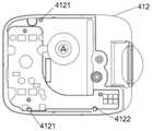
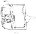
图15a为根据本发明实施例的输注结构410的爆炸图。图15b为根据本发明一个实施例 的下壳体的结构示意图。图15c为根据本发明一个实施例的主框架的结构示意图。Figure 15a is an exploded view of an
输注结构410包括上壳体411,下壳体412和设置于上壳体411和下壳体412之间的主 框架417。上壳体411上设置有多个上壳体第一卡合部4111和上壳体第二卡合部4112,下壳 体412上设置有多个下壳体第一卡合部4121和下壳体第二卡合部4122,主框架417上设置 有与上壳体第一卡合部4111和下壳体第一卡合部4121同时进行卡合的主框架第一卡合部 4171,增加主框架417与上壳体411和下壳体412纵向卡合的稳定性,同时减少卡合设计的 复杂度。上壳体第二卡合部4112和下壳体第二卡合部4122在主框架的侧边进行卡合,卡合 后可防止主框架417横向移动,增加主框架417与上壳体411和下壳体412横向卡合的稳定 性。在这里,“纵向”是指输注装置的厚度方向,“横向”是指输注装置的长度方向,如图3a所 示。各卡合部包括能够互相配合卡合的卡勾、卡块、卡孔、卡槽中的一种或多种,其位置可 根据控上壳体411,下壳体412和主框架417的形状结构而灵活设计,在这里并不作具体限 制,只要能实现上壳体411,下壳体412和主框架417的横向和纵向卡合稳定性即可。The
下壳体412上设置有电路板,用于向特定的结构单元供电,电路板为刚性电路板或者柔 性电路板。优选的,在本发明实施例中,电路板为柔性电路板。柔性电路板形状可塑,可根 据输注结构410内部空间灵活设计其形状。同时,柔性电路板上可设置多个连接端与主框架 417上的各电连接端子电连接,优化电路结构,从而实现输注结构410内部的电路导通,提 高各结构的电连接稳定性。A circuit board is provided on the
主框架417用于承载输注结构410内部的各结构,在这里,主框架417朝向上壳体411 的一侧为上侧,朝向下壳体412的一侧为下侧,以储药筒的开口端为界限,用于容纳储药筒 的一侧为右侧,另一侧为左侧。在这里需要说明的是“上侧”、“下侧”、“左侧”和“右侧”是相 对位置概念,位置关系如图15a所示。主框架417的右侧设置有储药筒容纳腔,用于容纳储 药筒,形状与储药筒相适应,主框架417的下侧设置有多个突出部4173,用于承载储药筒, 主框架417的右侧还设置有多个主框架第二卡合部4172,储药筒外侧设置有多个储药筒卡合 部(未示出),与主框架第二卡合部4172卡合,使储药筒和主框架417稳定连接。The
主框架417上侧的左侧上设置有驱动轮组件和电源,电源为双排电池,分别设置在驱动 轮组件的两侧。输注结构410中的电连接元件均设置在主框架417下侧的左侧上,电源通过 近似呈“L”型的弹性导电件向与电路板相连的各部件供电,实现输注结构410内部的电路导通。 如图4a和图4c所示,主框架417上设置有多个弹性导电体136的定位柱138,位置与电源位 置相适应,用于固定弹性导电体136;主框架417上还设置有通孔4174(如图15a所示),弹性 导电体136通过通孔4174实现主框架137上下两侧的电源和电路板的电连接,进而实现向各 部件供电;还设置有转轴1315,用于套设驱动单元1310并为驱动单元1310的旋转提供支点, 设置于驱动轮134之间;驱动单元1310的端部还设置有导电挡墙1318,用于限定驱动单元 的运动终点;驱动单元1310上还设置有导电塔簧1315,用于连接驱动单元1310和电路板, 导电塔簧1315中间小两端大,可以在固定驱动单元1310的同时提高与电路板的电连接稳定 性;导电台1314和弹性导电体1316之间还设置有多个动力部件1311的定位台1319,使动 力部件1311只能沿着各定位台1319之间限定的直线位置布置,防止动力部件1311因触碰到 其他导电元件而造成短路,使输注装置失效;端部还设置有导电台定位柱1317和挡块1316, 用于固定导电台134,如图7所示。各部件的具体结构如前所述,在此不再叙述。通过上述 主框架417的设置,输注结构410的各部件均能集成在主框架417上,充分利用了输注结构 410的内部空间,提高内部结构的集成度,有效减小输注结构410的体积,同时又能保证各 部件的结构稳定性和电连接稳定性,提高输注结构410内部结构的电连接可靠性。The left side of the upper side of the
在本发明实施例中,主框架417可以是包括其上侧、下侧、左侧和右侧结构的一体注塑 件,也可以是由各结构拼接而一体化,如部分结构为一体注塑件再与其他结构拼接成型,或 各结构之间相互拼接成型。各结构的内部也可以根据实际的需求选择一体件或是拼接而一体 化,在此并不做具体限制。当主框架417为一体件时,工艺简单,体积小,连接牢固,节省 材料,降低成本;当主框架417为拼接而一体化时,可根据主框架所需要承载的部件要求灵 活选择,优化输注结构内部设计。In the embodiment of the present invention, the
综上所述,本发明公开了一种贴片式药物输注装置,输注结构的弹性导电件上设置有凸 起,可以增强弹性导电体与电源和电路板或立体上的特定连接端的电连接稳定性,提高电连 接的可靠性。In summary, the present invention discloses a patch-type drug infusion device. The elastic conductive member of the infusion structure is provided with protrusions, which can enhance the electrical connection between the elastic conductive body and the power supply and the specific connection end on the circuit board or stereo. Connection stability, improve the reliability of electrical connection.
虽然已经通过示例对本发明的一些特定实施例进行了详细说明,但是本领域的技术人员 应该理解,以上示例仅是为了进行说明,而不是为了限制本发明的范围。本领域的技术人员 应该理解,可在不脱离本发明的范围和精神的情况下,对以上实施例进行修改。本发明的范 围由所附权利要求来限定。While some specific embodiments of the present invention have been described in detail by way of example, those skilled in the art will appreciate that the above examples are intended to be illustrative only and not intended to limit the scope of the invention. Those skilled in the art will appreciate that modifications may be made to the above embodiments without departing from the scope and spirit of the present invention. The scope of the invention is defined by the appended claims.
Claims (17)
Translated fromChineseApplications Claiming Priority (2)
| Application Number | Priority Date | Filing Date | Title |
|---|---|---|---|
| CNPCT/CN2021/070207 | 2021-01-05 | ||
| PCT/CN2021/070207WO2022088498A1 (en) | 2020-10-30 | 2021-01-05 | A patch-type drug infusion device |
Publications (1)
| Publication Number | Publication Date |
|---|---|
| CN114712604Atrue CN114712604A (en) | 2022-07-08 |
Family
ID=80771260
Family Applications (12)
| Application Number | Title | Priority Date | Filing Date |
|---|---|---|---|
| CN202110802296.9APendingCN115554520A (en) | 2021-01-05 | 2021-07-15 | Paster type drug infusion device |
| CN202121986933.4UActiveCN216124956U (en) | 2021-01-05 | 2021-08-23 | Patch type drug infusion system |
| CN202110969637.1AActiveCN114588390B (en) | 2020-12-04 | 2021-08-23 | Patch Drug Infusion System |
| CN202110969709.2APendingCN114712601A (en) | 2021-01-05 | 2021-08-23 | Patch type drug infusion system |
| CN202111064027.3APendingCN114712605A (en) | 2021-01-05 | 2021-09-10 | patch drug infusion device |
| CN202111064032.4APendingCN114712607A (en) | 2021-01-05 | 2021-09-10 | patch drug infusion device |
| CN202111062264.6APendingCN114712602A (en) | 2021-01-05 | 2021-09-10 | patch drug infusion device |
| CN202111064030.5APendingCN114712606A (en) | 2021-01-05 | 2021-09-10 | patch drug infusion device |
| CN202111064070.XAActiveCN114712616B (en) | 2021-01-05 | 2021-09-10 | Patch type medicine infusion device |
| CN202111062322.5APendingCN114712603A (en) | 2021-01-05 | 2021-09-10 | patch drug infusion device |
| CN202111064020.1APendingCN114712604A (en) | 2021-01-05 | 2021-09-10 | patch drug infusion device |
| CN202210931614.6AActiveCN115779189B (en) | 2021-01-05 | 2022-08-04 | Elastic anti-reversal drug infusion device |
Family Applications Before (10)
| Application Number | Title | Priority Date | Filing Date |
|---|---|---|---|
| CN202110802296.9APendingCN115554520A (en) | 2021-01-05 | 2021-07-15 | Paster type drug infusion device |
| CN202121986933.4UActiveCN216124956U (en) | 2021-01-05 | 2021-08-23 | Patch type drug infusion system |
| CN202110969637.1AActiveCN114588390B (en) | 2020-12-04 | 2021-08-23 | Patch Drug Infusion System |
| CN202110969709.2APendingCN114712601A (en) | 2021-01-05 | 2021-08-23 | Patch type drug infusion system |
| CN202111064027.3APendingCN114712605A (en) | 2021-01-05 | 2021-09-10 | patch drug infusion device |
| CN202111064032.4APendingCN114712607A (en) | 2021-01-05 | 2021-09-10 | patch drug infusion device |
| CN202111062264.6APendingCN114712602A (en) | 2021-01-05 | 2021-09-10 | patch drug infusion device |
| CN202111064030.5APendingCN114712606A (en) | 2021-01-05 | 2021-09-10 | patch drug infusion device |
| CN202111064070.XAActiveCN114712616B (en) | 2021-01-05 | 2021-09-10 | Patch type medicine infusion device |
| CN202111062322.5APendingCN114712603A (en) | 2021-01-05 | 2021-09-10 | patch drug infusion device |
Family Applications After (1)
| Application Number | Title | Priority Date | Filing Date |
|---|---|---|---|
| CN202210931614.6AActiveCN115779189B (en) | 2021-01-05 | 2022-08-04 | Elastic anti-reversal drug infusion device |
Country Status (4)
| Country | Link |
|---|---|
| US (12) | US20240050649A1 (en) |
| EP (13) | EP4274641A4 (en) |
| CN (12) | CN115554520A (en) |
| WO (14) | WO2022147985A1 (en) |
Cited By (2)
| Publication number | Priority date | Publication date | Assignee | Title |
|---|---|---|---|---|
| CN115137913A (en)* | 2022-07-14 | 2022-10-04 | 湖南千山医疗器械有限公司 | Disposable liquid medicine infusion device |
| WO2024011694A1 (en)* | 2022-07-14 | 2024-01-18 | 湖南千山医疗器械有限公司 | Disposable insulin pump |
Families Citing this family (6)
| Publication number | Priority date | Publication date | Assignee | Title |
|---|---|---|---|---|
| CN119950880A (en) | 2017-05-05 | 2025-05-09 | 里珍纳龙药品有限公司 | Auto-injectors and related methods of use |
| WO2022147985A1 (en)* | 2021-01-05 | 2022-07-14 | Medtrum Technologies Inc. | A skin patch drug infusion device |
| US11419976B1 (en) | 2021-04-30 | 2022-08-23 | Fresenius Kabi Deutschland Gmbh | Wearable drug delivery device with pressurized fluid dispensing |
| USD1007676S1 (en) | 2021-11-16 | 2023-12-12 | Regeneron Pharmaceuticals, Inc. | Wearable autoinjector |
| CN116328081B (en)* | 2023-04-07 | 2025-04-11 | 北京艺升控股有限公司 | An injection system |
| CN116328084B (en)* | 2023-04-10 | 2025-08-05 | 江苏爱朋医疗科技股份有限公司 | injection pump |
Citations (5)
| Publication number | Priority date | Publication date | Assignee | Title |
|---|---|---|---|---|
| CN204379897U (en)* | 2014-12-09 | 2015-06-10 | 杨利波 | A kind of infusion pump |
| CN104784777A (en)* | 2014-01-20 | 2015-07-22 | 上海移宇科技有限公司 | Ductless medicine fluid infusion device |
| CN107469185A (en)* | 2017-09-15 | 2017-12-15 | 金明必 | Pump transfusion means for insulin and the portable mini docile type insulin pump with this device |
| CN110881983A (en)* | 2019-11-20 | 2020-03-17 | 浙江大学 | Flexible minimally invasive blood glucose sensor |
| CN112120709A (en)* | 2020-09-27 | 2020-12-25 | 微泰医疗器械(杭州)有限公司 | Blood sugar monitoring device |
Family Cites Families (117)
| Publication number | Priority date | Publication date | Assignee | Title |
|---|---|---|---|---|
| US5217442A (en)* | 1990-09-28 | 1993-06-08 | Minimed Technologies | Aspiration and refill kit for a medication infusion pump |
| US7621893B2 (en)* | 1998-10-29 | 2009-11-24 | Medtronic Minimed, Inc. | Methods and apparatuses for detecting occlusions in an ambulatory infusion pump |
| US6589229B1 (en)* | 2000-07-31 | 2003-07-08 | Becton, Dickinson And Company | Wearable, self-contained drug infusion device |
| JP4058498B2 (en)* | 2001-02-23 | 2008-03-12 | ストライカー コーポレイション | Integrated drug delivery system |
| EP1815879A3 (en)* | 2001-05-18 | 2007-11-14 | Deka Products Limited Partnership | Infusion set for a fluid pump |
| US20050238507A1 (en)* | 2002-04-23 | 2005-10-27 | Insulet Corporation | Fluid delivery device |
| CN100479875C (en)* | 2002-07-22 | 2009-04-22 | 贝克顿·迪金森公司 | Patch-like infusion device |
| JP2007530860A (en)* | 2004-03-30 | 2007-11-01 | ノボ・ノルデイスク・エー/エス | Actuator system having detection means |
| EP1830699A2 (en)* | 2004-12-22 | 2007-09-12 | Novo Nordisk A/S | Sensor system and method for detecting problems with mounting of skin mountable medical devices |
| CN101107025A (en)* | 2005-01-17 | 2008-01-16 | 诺和诺德公司 | Fluid delivery device with integrated monitoring of physiological characteristics |
| US7905868B2 (en)* | 2006-08-23 | 2011-03-15 | Medtronic Minimed, Inc. | Infusion medium delivery device and method with drive device for driving plunger in reservoir |
| US7534226B2 (en)* | 2005-09-26 | 2009-05-19 | M2 Group Holdings, Inc. | Dispensing fluid from an infusion pump system |
| US8475408B2 (en)* | 2005-11-08 | 2013-07-02 | Asante Solutions, Inc. | Infusion pump system |
| US20070255227A1 (en)* | 2006-04-27 | 2007-11-01 | Haase James M | Methods and apparatus for refilling an infusion device |
| JP4805724B2 (en)* | 2006-05-16 | 2011-11-02 | テルモ株式会社 | Syringe pump |
| US7794434B2 (en)* | 2006-08-23 | 2010-09-14 | Medtronic Minimed, Inc. | Systems and methods allowing for reservoir filling and infusion medium delivery |
| WO2008103175A1 (en)* | 2007-02-22 | 2008-08-28 | M2 Group Holdings, Inc. | Portable infusion pump with flexible piston rod |
| US20100286467A1 (en)* | 2007-03-19 | 2010-11-11 | Benny Pesach | Device for drug delivery and associated connections thereto |
| US8434528B2 (en)* | 2007-04-30 | 2013-05-07 | Medtronic Minimed, Inc. | Systems and methods for reservoir filling |
| US8323250B2 (en)* | 2007-04-30 | 2012-12-04 | Medtronic Minimed, Inc. | Adhesive patch systems and methods |
| EP2180821B1 (en)* | 2007-07-20 | 2014-05-07 | Roche Diagnostics GmbH | Energy supply for fluid dispensing device |
| US8147446B2 (en)* | 2007-08-01 | 2012-04-03 | Medingo Ltd. | Detachable portable infusion device |
| US7879026B2 (en)* | 2007-09-07 | 2011-02-01 | Asante Solutions, Inc. | Controlled adjustment of medicine dispensation from an infusion pump device |
| SE532495C2 (en)* | 2007-12-13 | 2010-02-09 | Moelnlycke Health Care Ab | Bandages to protect the skin from objects that protrude from it |
| US7976505B2 (en)* | 2007-12-19 | 2011-07-12 | Calibra Medical, Inc. | Disposable infusion device negative pressure filling apparatus and method |
| US9526830B2 (en)* | 2007-12-31 | 2016-12-27 | Deka Products Limited Partnership | Wearable pump assembly |
| US20110160640A1 (en)* | 2008-01-18 | 2011-06-30 | Yanaki Jamal S | Operation management of active transdermal medicament patch |
| US9375529B2 (en)* | 2009-09-02 | 2016-06-28 | Becton, Dickinson And Company | Extended use medical device |
| US8939928B2 (en)* | 2009-07-23 | 2015-01-27 | Becton, Dickinson And Company | Medical device having capacitive coupling communication and energy harvesting |
| US10071198B2 (en)* | 2012-11-02 | 2018-09-11 | West Pharma. Servicees IL, Ltd. | Adhesive structure for medical device |
| AU2010325518A1 (en)* | 2009-11-30 | 2012-06-14 | F.Hoffmann-La Roche Ag | Analyte monitoring and fluid dispensing system |
| US9421321B2 (en)* | 2009-12-30 | 2016-08-23 | Medtronic Minimed, Inc. | Connection and alignment systems and methods |
| CN201869974U (en)* | 2010-08-09 | 2011-06-22 | 许福义 | Folding protective sleeve |
| US9381300B2 (en)* | 2010-09-24 | 2016-07-05 | Perqflo, Llc | Infusion pumps |
| DE102010049895B4 (en)* | 2010-10-29 | 2016-02-11 | Primed Halberstadt Medizintechnik Gmbh | Halpflaster for tracheal cannulas or artificial noses with speaking valve |
| CN102178580A (en)* | 2011-05-12 | 2011-09-14 | 李明宙 | Adhesive plaster for skin and use method |
| DK2714141T3 (en)* | 2011-05-25 | 2018-10-08 | Sanofi Aventis Deutschland | MEDICINAL INJECTION DEVICE AND PRELIMINARY OPERATION |
| CN202146467U (en)* | 2011-06-15 | 2012-02-22 | 广州市暨华医疗器械有限公司 | Heparin pump with speed detecting structure |
| CN202342305U (en)* | 2011-11-30 | 2012-07-25 | 泰州市三易医疗科技有限公司 | Medical aquogel wound dressing |
| CN204910157U (en)* | 2012-03-05 | 2015-12-30 | 贝克顿·迪金森公司 | System for be used for at body liquid conveying |
| US9381297B2 (en)* | 2012-06-07 | 2016-07-05 | Tandem Diabetes Care, Inc. | Sealed infusion device with electrical connector port |
| CN104352305B (en)* | 2012-06-26 | 2017-02-22 | 陕西远光高科技有限公司 | Wound dressing capable of promoting wound to be rapidly healed |
| CN104619368B (en)* | 2012-07-31 | 2018-11-30 | 三伟达保健系统有限责任公司 | For the device and method from infusion pump distribution fluid |
| HK1210974A1 (en)* | 2012-08-20 | 2016-05-13 | F. Hoffmann-La Roche Ag | Therapeutic system with an adaptor for an infusion set |
| US8808269B2 (en)* | 2012-08-21 | 2014-08-19 | Medtronic Minimed, Inc. | Reservoir plunger position monitoring and medical device incorporating same |
| US9870450B2 (en)* | 2012-09-11 | 2018-01-16 | Zolo Solutions, Inc. | Drug delivery regulator |
| CN202874180U (en)* | 2012-09-19 | 2013-04-17 | 高树仪 | A protective case for a portable electronic product |
| JP2014079325A (en)* | 2012-10-15 | 2014-05-08 | Seiko Epson Corp | Fluid injection apparatus |
| JP2016500013A (en)* | 2012-10-16 | 2016-01-07 | スイスイノヴ プロダクト サールSwissinnov Product Sarl | Fluid supply system and method |
| JP2014087449A (en)* | 2012-10-30 | 2014-05-15 | Seiko Epson Corp | Liquid transport device and method for determining catheter drop-out |
| US9308321B2 (en)* | 2013-02-18 | 2016-04-12 | Medtronic Minimed, Inc. | Infusion device having gear assembly initialization |
| CN103309406A (en)* | 2013-05-14 | 2013-09-18 | 张瑞洋 | A protective case for a tablet computer |
| WO2015095639A1 (en)* | 2013-12-20 | 2015-06-25 | Becton, Dickinson And Company | Infusion set adhesive systems |
| WO2015157174A1 (en)* | 2014-04-07 | 2015-10-15 | Becton, Dickinson And Company | Rotational metering pump for insulin patch |
| EP3134153B1 (en)* | 2014-04-24 | 2024-07-31 | Becton, Dickinson and Company | Catheter insertion device |
| US10279106B1 (en)* | 2014-05-08 | 2019-05-07 | Tandem Diabetes Care, Inc. | Insulin patch pump |
| EP3145561A1 (en)* | 2014-05-20 | 2017-03-29 | Cequr SA | Medicine delivery device with restricted access filling port |
| US9452255B2 (en)* | 2014-07-21 | 2016-09-27 | Medtronic Minimed, Inc. | Smart connection interface |
| CN105311702B (en)* | 2014-09-03 | 2019-10-08 | 上海移宇科技股份有限公司 | Disposable duct free drug infusion system |
| EP3191041B1 (en)* | 2014-09-10 | 2022-06-08 | C. R. Bard, Inc. | Protective dressing for skin-placed medical device |
| CN106714872B (en)* | 2014-09-15 | 2020-07-17 | 赛诺菲 | Bulk dermal patch drug delivery device with integrated skin disinfection mechanism for injection site |
| WO2016054404A2 (en)* | 2014-10-03 | 2016-04-07 | Enable Injections, Llc | Medical fluid transfer and injection apparatus and method |
| US10413661B2 (en)* | 2015-01-15 | 2019-09-17 | Deka Products Limited Partnership | Infusion device system and apparatus |
| JP2018505756A (en)* | 2015-02-18 | 2018-03-01 | インシュレット コーポレイション | Fluid delivery and infusion device and method of use thereof |
| EP3260148B1 (en)* | 2015-02-20 | 2022-03-02 | Terumo Kabushiki Kaisha | Liquid drug administration device |
| US10010668B2 (en)* | 2015-06-22 | 2018-07-03 | Medtronic Minimed, Inc. | Occlusion detection techniques for a fluid infusion device having a rotary pump mechanism and a force sensor |
| CN204906692U (en)* | 2015-07-28 | 2015-12-23 | 瑞声光电科技(常州)有限公司 | Loudspeaker module group |
| EP3162395A1 (en)* | 2015-10-28 | 2017-05-03 | NNE Pharmaplan A/S | Single-use auto-injector |
| US10716896B2 (en)* | 2015-11-24 | 2020-07-21 | Insulet Corporation | Wearable automated medication delivery system |
| JOP20170042B1 (en)* | 2016-02-12 | 2022-09-15 | Amgen Inc | Means of drug delivery, method of manufacture and method of use |
| CN205434547U (en)* | 2016-02-24 | 2016-08-10 | 中国人民解放军第三〇九医院 | Disposable transparent pad pasting safety is fixed pastes |
| US20170290535A1 (en)* | 2016-04-08 | 2017-10-12 | Medtronic Minimed, Inc. | Analyte sensor with indicators |
| WO2017181324A1 (en)* | 2016-04-18 | 2017-10-26 | Medtrum Technologies Inc. | A unilateral driving mechanism for a portable infusion system |
| US10589038B2 (en)* | 2016-04-27 | 2020-03-17 | Medtronic Minimed, Inc. | Set connector systems for venting a fluid reservoir |
| EP4552567A1 (en)* | 2016-05-02 | 2025-05-14 | DexCom, Inc. | System for providing alerts optimized for a user |
| CN106110445B (en)* | 2016-08-12 | 2019-12-03 | 上海移宇科技股份有限公司 | Infusion system of a portable drug infusion device |
| KR101860928B1 (en)* | 2016-10-18 | 2018-05-24 | 이오플로우 주식회사 | Medical liquid dispensing device |
| EP3338832A1 (en)* | 2016-12-23 | 2018-06-27 | Sanofi-Aventis Deutschland GmbH | Medicament delivery device |
| EP3558186A4 (en)* | 2016-12-26 | 2020-08-26 | Metronom Health, Inc. | ADHESIVE SYSTEMS WITH OUTER RING MADE OF AGGRESSIVE ADHESIVE AND WITH LOW MODULE OF ELASTICITY |
| EP3562395A4 (en)* | 2016-12-30 | 2020-07-22 | Medtrum Technologies Inc. | SYSTEM AND METHOD FOR A CLOSED CONTROL CIRCUIT IN AN ARTIFICIAL LEAKAGE |
| CN108261585B (en)* | 2016-12-30 | 2022-06-07 | 上海移宇科技股份有限公司 | System and method for closed-loop control of artificial pancreas |
| WO2018195310A1 (en)* | 2017-04-20 | 2018-10-25 | Becton, Dickinson And Company | Insulin leakage sensor with electric control to stop insulin flow |
| CN119950880A (en)* | 2017-05-05 | 2025-05-09 | 里珍纳龙药品有限公司 | Auto-injectors and related methods of use |
| KR20180127027A (en)* | 2017-05-19 | 2018-11-28 | 포항공과대학교 산학협력단 | Drug injection device |
| WO2018222697A1 (en)* | 2017-05-30 | 2018-12-06 | West Pharma. Services IL, Ltd. | Vertical assembly of pcb |
| JP2020531071A (en)* | 2017-08-22 | 2020-11-05 | ステディメッド, エルティーディー.Steadymed, Ltd. | Selective mechanical startable filled injection pump device |
| CN208511685U (en)* | 2017-08-29 | 2019-02-19 | 丁珊珊 | A kind of fixed application of medical drainage tube |
| CN107583144B (en)* | 2017-09-13 | 2020-08-04 | 浙江大学 | High-precision safe microinjection pump and method for multi-brand syringes |
| CN107681312B (en)* | 2017-09-21 | 2020-08-21 | Oppo广东移动通信有限公司 | Connecting structures, sound-generating assemblies, mobile terminals, electronic devices and circuit board assemblies |
| KR102002694B1 (en)* | 2017-09-29 | 2019-07-23 | 주식회사 새한마이크로텍 | Conductive contact and anisotropic conductive sheet with the same |
| JP7293217B2 (en)* | 2017-10-30 | 2023-06-19 | デックスコム・インコーポレーテッド | Diabetes Management Partner Interface for Wireless Communication of Analyte Data |
| EP3485935A1 (en)* | 2017-11-21 | 2019-05-22 | Tecpharma Licensing AG | A one way coupling for an injection or an infusion device |
| US11439352B2 (en)* | 2018-01-17 | 2022-09-13 | Medtronic Minimed, Inc. | Medical device with adhesive patch longevity |
| CN108295335A (en)* | 2018-01-26 | 2018-07-20 | 美敦力公司 | Sticking type fluid infusion apparatus and infusion needle protector |
| WO2019149868A1 (en)* | 2018-02-05 | 2019-08-08 | Sanofi | Pressure sensor assembly and methods for injection devices |
| EP3539592A1 (en)* | 2018-03-15 | 2019-09-18 | Tecpharma Licensing AG | An injection or infusion device comprising an improved housing and release liner for removing sterile barrier films using the release liner |
| JP7001512B2 (en)* | 2018-03-22 | 2022-01-19 | テルモ株式会社 | Electronics |
| CA3101966A1 (en)* | 2018-05-29 | 2019-12-05 | Morningside Venture Investments Limited | Drug delivery methods and systems |
| WO2020021056A1 (en)* | 2018-07-27 | 2020-01-30 | CSL Behring Lengnau AG | Infusion device having a gripper mechanism |
| CA3051543A1 (en)* | 2018-08-30 | 2020-02-29 | Becton, Dickinson And Company | Liquid medicament reservoir empty detection sensor and occlusion sensor for medicament delivery device |
| CN109269674B (en)* | 2018-10-25 | 2024-07-26 | 深圳刷新生物传感科技有限公司 | Body temperature testing device |
| HUE063930T2 (en)* | 2018-12-21 | 2024-02-28 | Hoffmann La Roche | A medical device that can be applied to the skin |
| US11109800B2 (en)* | 2019-01-04 | 2021-09-07 | Enable Injections, Inc. | Medical fluid injection apparatus and method with detachable patch and monitoring |
| WO2020233484A1 (en)* | 2019-05-17 | 2020-11-26 | Medtrum Technologies Inc. | Drug infusion device with multiple infusion modes |
| US12403247B2 (en)* | 2019-05-17 | 2025-09-02 | Medtrum Technologies Inc. | Drug infusion device |
| CN111939387B (en)* | 2019-05-17 | 2022-12-09 | 上海移宇科技股份有限公司 | Drug infusion device with multiple infusion modes |
| WO2020233486A1 (en)* | 2019-05-17 | 2020-11-26 | Medtrum Technologies Inc. | Bilaterally driven drug infusion device with multiple infusion modes |
| CN210698397U (en)* | 2019-06-20 | 2020-06-09 | 南充市中心医院 | Rhombus anti-curling adhesive tape |
| WO2021012852A1 (en)* | 2019-07-19 | 2021-01-28 | Medtrum Technologies Inc. | Unilateral-driven medical device with infusion and detection integrated |
| US20220218895A1 (en)* | 2019-08-01 | 2022-07-14 | Medtrum Technologies Inc. | Driving apparatus and drug infusion device |
| CN112295050B (en)* | 2019-08-01 | 2023-06-06 | 上海移宇科技股份有限公司 | Drives and Drug Infusion Devices |
| CN111053956A (en)* | 2019-12-24 | 2020-04-24 | 微泰医疗器械(杭州)有限公司 | Dosing device and dosing pump system |
| EP4093460A4 (en)* | 2020-01-21 | 2023-09-27 | Medtrum Technologies Inc. | Medical device with safety verification and safety verification method thereof |
| US20230310740A1 (en)* | 2020-09-08 | 2023-10-05 | Medtrum Technologies Inc. | Infusion needle structure of drug infusion device |
| US11241530B1 (en)* | 2020-11-23 | 2022-02-08 | Amf Medical Sa | Insulin patch pump having photoplethysmography module |
| US20240115800A1 (en)* | 2021-01-05 | 2024-04-11 | Medtrum Technologies Inc. | Drug infusion device with security base |
| WO2022147985A1 (en)* | 2021-01-05 | 2022-07-14 | Medtrum Technologies Inc. | A skin patch drug infusion device |
- 2021
- 2021-07-02WOPCT/CN2021/104147patent/WO2022147985A1/ennot_activeCeased
- 2021-07-02USUS18/268,247patent/US20240050649A1/enactivePending
- 2021-07-02EPEP21917029.7Apatent/EP4274641A4/enactivePending
- 2021-07-15WOPCT/CN2021/106462patent/WO2023272784A1/ennot_activeCeased
- 2021-07-15USUS18/571,721patent/US20240285851A1/enactivePending
- 2021-07-15CNCN202110802296.9Apatent/CN115554520A/enactivePending
- 2021-07-15EPEP21947727.0Apatent/EP4337284A4/enactivePending
- 2021-08-23WOPCT/CN2021/114029patent/WO2022148023A1/ennot_activeCeased
- 2021-08-23CNCN202121986933.4Upatent/CN216124956U/enactiveActive
- 2021-08-23CNCN202110969637.1Apatent/CN114588390B/enactiveActive
- 2021-08-23CNCN202110969709.2Apatent/CN114712601A/enactivePending
- 2021-08-23USUS18/269,958patent/US20240316263A1/enactivePending
- 2021-08-23WOPCT/CN2021/114054patent/WO2022116603A1/ennot_activeCeased
- 2021-08-23EPEP21899639.5Apatent/EP4255551A4/enactivePending
- 2021-08-23USUS18/035,939patent/US20240017000A1/enactivePending
- 2021-08-23EPEP21917066.9Apatent/EP4274636A4/enactivePending
- 2021-09-10USUS18/270,226patent/US20240066212A1/enactivePending
- 2021-09-10WOPCT/CN2021/117744patent/WO2022148045A1/ennot_activeCeased
- 2021-09-10WOPCT/CN2021/117730patent/WO2022148044A1/ennot_activeCeased
- 2021-09-10EPEP21917090.9Apatent/EP4274634A4/enactivePending
- 2021-09-10EPEP21917089.1Apatent/EP4274639A4/enactivePending
- 2021-09-10CNCN202111064027.3Apatent/CN114712605A/enactivePending
- 2021-09-10CNCN202111064032.4Apatent/CN114712607A/enactivePending
- 2021-09-10EPEP21917087.5Apatent/EP4274638A4/enactivePending
- 2021-09-10CNCN202111062264.6Apatent/CN114712602A/enactivePending
- 2021-09-10USUS18/268,611patent/US20240082491A1/enactivePending
- 2021-09-10WOPCT/CN2021/117757patent/WO2022148047A1/ennot_activeCeased
- 2021-09-10CNCN202111064030.5Apatent/CN114712606A/enactivePending
- 2021-09-10USUS18/269,757patent/US20240139411A1/enactivePending
- 2021-09-10CNCN202111064070.XApatent/CN114712616B/enactiveActive
- 2021-09-10WOPCT/CN2021/117647patent/WO2022148041A1/ennot_activeCeased
- 2021-09-10EPEP21917088.3Apatent/EP4274633A4/enactivePending
- 2021-09-10EPEP21917085.9Apatent/EP4274631A4/enactivePending
- 2021-09-10WOPCT/CN2021/117684patent/WO2022148043A1/ennot_activeCeased
- 2021-09-10WOPCT/CN2021/117678patent/WO2022148042A1/ennot_activeCeased
- 2021-09-10WOPCT/CN2021/117749patent/WO2022148046A1/ennot_activeCeased
- 2021-09-10USUS18/269,759patent/US20240058525A1/enactivePending
- 2021-09-10USUS18/269,961patent/US20240066211A1/enactivePending
- 2021-09-10EPEP21917091.7Apatent/EP4274642A4/enactivePending
- 2021-09-10USUS18/269,957patent/US20240316262A1/enactivePending
- 2021-09-10WOPCT/CN2021/117761patent/WO2022148048A1/ennot_activeCeased
- 2021-09-10CNCN202111062322.5Apatent/CN114712603A/enactivePending
- 2021-09-10USUS18/269,758patent/US20240316261A1/enactivePending
- 2021-09-10EPEP21917086.7Apatent/EP4274632A4/enactivePending
- 2021-09-10CNCN202111064020.1Apatent/CN114712604A/enactivePending
- 2022
- 2022-08-03USUS18/569,224patent/US20240285850A1/enactivePending
- 2022-08-03EPEP22866290.4Apatent/EP4337287A4/enactivePending
- 2022-08-03WOPCT/CN2022/110057patent/WO2023035816A1/ennot_activeCeased
- 2022-08-04CNCN202210931614.6Apatent/CN115779189B/enactiveActive
- 2023
- 2023-08-28EPEP23849553.5Apatent/EP4566640A1/enactivePending
- 2023-08-28WOPCT/CN2023/115289patent/WO2024027849A1/ennot_activeCeased
Patent Citations (5)
| Publication number | Priority date | Publication date | Assignee | Title |
|---|---|---|---|---|
| CN104784777A (en)* | 2014-01-20 | 2015-07-22 | 上海移宇科技有限公司 | Ductless medicine fluid infusion device |
| CN204379897U (en)* | 2014-12-09 | 2015-06-10 | 杨利波 | A kind of infusion pump |
| CN107469185A (en)* | 2017-09-15 | 2017-12-15 | 金明必 | Pump transfusion means for insulin and the portable mini docile type insulin pump with this device |
| CN110881983A (en)* | 2019-11-20 | 2020-03-17 | 浙江大学 | Flexible minimally invasive blood glucose sensor |
| CN112120709A (en)* | 2020-09-27 | 2020-12-25 | 微泰医疗器械(杭州)有限公司 | Blood sugar monitoring device |
Cited By (3)
| Publication number | Priority date | Publication date | Assignee | Title |
|---|---|---|---|---|
| CN115137913A (en)* | 2022-07-14 | 2022-10-04 | 湖南千山医疗器械有限公司 | Disposable liquid medicine infusion device |
| WO2024011688A1 (en)* | 2022-07-14 | 2024-01-18 | 湖南千山医疗器械有限公司 | Disposable liquid medication infusion device |
| WO2024011694A1 (en)* | 2022-07-14 | 2024-01-18 | 湖南千山医疗器械有限公司 | Disposable insulin pump |
Also Published As
Similar Documents
| Publication | Publication Date | Title |
|---|---|---|
| CN114712604A (en) | patch drug infusion device | |
| WO2022148268A1 (en) | Integrated skin patch artifical pancreas | |
| CN114712610B (en) | Reinforced medicine infusion device | |
| CN114432538A (en) | patch drug infusion device | |
| CN114712608B (en) | Patch drug infusion device | |
| CN114712612B (en) | Integrated patch-type artificial pancreas |
Legal Events
| Date | Code | Title | Description |
|---|---|---|---|
| PB01 | Publication | ||
| PB01 | Publication | ||
| SE01 | Entry into force of request for substantive examination | ||
| SE01 | Entry into force of request for substantive examination |