CN114711472A - Aerosol generating device, control method thereof and charging system comprising device - Google Patents
Aerosol generating device, control method thereof and charging system comprising deviceDownload PDFInfo
- Publication number
- CN114711472A CN114711472ACN202111499276.5ACN202111499276ACN114711472ACN 114711472 ACN114711472 ACN 114711472ACN 202111499276 ACN202111499276 ACN 202111499276ACN 114711472 ACN114711472 ACN 114711472A
- Authority
- CN
- China
- Prior art keywords
- generating device
- aerosol generating
- heater
- conductive pattern
- magnet
- Prior art date
- Legal status (The legal status is an assumption and is not a legal conclusion. Google has not performed a legal analysis and makes no representation as to the accuracy of the status listed.)
- Pending
Links
- 238000000034methodMethods0.000titleclaimsabstractdescription34
- 239000000443aerosolSubstances0.000titleclaimsdescription203
- 235000019504cigarettesNutrition0.000claimsabstractdescription89
- 238000010438heat treatmentMethods0.000claimsabstractdescription17
- 238000003860storageMethods0.000claimsdescription66
- 239000000126substanceSubstances0.000claimsdescription35
- 239000000919ceramicSubstances0.000claimsdescription30
- 239000013078crystalSubstances0.000claimsdescription28
- 239000011241protective layerSubstances0.000claimsdescription23
- 239000000758substrateSubstances0.000claimsdescription17
- 230000002093peripheral effectEffects0.000claimsdescription15
- 239000000463materialSubstances0.000claimsdescription13
- 230000004913activationEffects0.000claimsdescription7
- 230000008569processEffects0.000claimsdescription7
- 239000010949copperSubstances0.000claimsdescription5
- 230000000694effectsEffects0.000claimsdescription5
- 230000002779inactivationEffects0.000claimsdescription5
- RYGMFSIKBFXOCR-UHFFFAOYSA-NCopperChemical compound[Cu]RYGMFSIKBFXOCR-UHFFFAOYSA-N0.000claimsdescription4
- 229910052802copperInorganic materials0.000claimsdescription4
- 238000004140cleaningMethods0.000claimsdescription3
- 238000007641inkjet printingMethods0.000claimsdescription3
- 239000010409thin filmSubstances0.000claimsdescription3
- 239000003571electronic cigaretteSubstances0.000description19
- 238000010586diagramMethods0.000description18
- 230000008016vaporizationEffects0.000description12
- 238000009834vaporizationMethods0.000description11
- 239000011364vaporized materialSubstances0.000description11
- 239000010408filmSubstances0.000description8
- 238000004891communicationMethods0.000description7
- 239000011521glassSubstances0.000description7
- 238000012986modificationMethods0.000description6
- 230000004048modificationEffects0.000description6
- 230000000391smoking effectEffects0.000description6
- 239000011253protective coatingSubstances0.000description5
- 239000007787solidSubstances0.000description5
- PXHVJJICTQNCMI-UHFFFAOYSA-NNickelChemical compound[Ni]PXHVJJICTQNCMI-UHFFFAOYSA-N0.000description4
- 239000011248coating agentSubstances0.000description4
- 238000000576coating methodMethods0.000description4
- 238000004519manufacturing processMethods0.000description4
- 239000002994raw materialSubstances0.000description4
- 239000000956alloySubstances0.000description3
- 230000003373anti-fouling effectEffects0.000description3
- 230000008901benefitEffects0.000description3
- 239000010419fine particleSubstances0.000description3
- 238000003780insertionMethods0.000description3
- 230000037431insertionEffects0.000description3
- 239000010410layerSubstances0.000description3
- 229910052759nickelInorganic materials0.000description3
- 229910000679solderInorganic materials0.000description3
- 229910045601alloyInorganic materials0.000description2
- 229910052782aluminiumInorganic materials0.000description2
- 229910010293ceramic materialInorganic materials0.000description2
- 238000002485combustion reactionMethods0.000description2
- 230000005611electricityEffects0.000description2
- 239000007772electrode materialSubstances0.000description2
- 239000007888film coatingSubstances0.000description2
- 238000009501film coatingMethods0.000description2
- 230000014509gene expressionEffects0.000description2
- 229910052737goldInorganic materials0.000description2
- 239000010931goldSubstances0.000description2
- 150000002500ionsChemical class0.000description2
- 229910000953kanthalInorganic materials0.000description2
- 239000007788liquidSubstances0.000description2
- 229910052751metalInorganic materials0.000description2
- 239000002184metalSubstances0.000description2
- 229910052697platinumInorganic materials0.000description2
- 230000001681protective effectEffects0.000description2
- 229910052709silverInorganic materials0.000description2
- 229910001220stainless steelInorganic materials0.000description2
- 229910052721tungstenInorganic materials0.000description2
- 229910000851Alloy steelInorganic materials0.000description1
- OKTJSMMVPCPJKN-UHFFFAOYSA-NCarbonChemical compound[C]OKTJSMMVPCPJKN-UHFFFAOYSA-N0.000description1
- 229910001182Mo alloyInorganic materials0.000description1
- 241000208125NicotianaSpecies0.000description1
- 235000002637Nicotiana tabacumNutrition0.000description1
- 229910004298SiO 2Inorganic materials0.000description1
- BQCADISMDOOEFD-UHFFFAOYSA-NSilverChemical compound[Ag]BQCADISMDOOEFD-UHFFFAOYSA-N0.000description1
- 230000002159abnormal effectEffects0.000description1
- 230000004308accommodationEffects0.000description1
- 230000001154acute effectEffects0.000description1
- XAGFODPZIPBFFR-UHFFFAOYSA-NaluminiumChemical compound[Al]XAGFODPZIPBFFR-UHFFFAOYSA-N0.000description1
- 230000006399behaviorEffects0.000description1
- 229910052799carbonInorganic materials0.000description1
- 239000002131composite materialSubstances0.000description1
- 239000000470constituentSubstances0.000description1
- 238000005520cutting processMethods0.000description1
- 238000005485electric heatingMethods0.000description1
- 238000005516engineering processMethods0.000description1
- PCHJSUWPFVWCPO-UHFFFAOYSA-NgoldChemical compound[Au]PCHJSUWPFVWCPO-UHFFFAOYSA-N0.000description1
- 230000020169heat generationEffects0.000description1
- 238000007689inspectionMethods0.000description1
- 230000007246mechanismEffects0.000description1
- 229910001092metal group alloyInorganic materials0.000description1
- 239000007769metal materialSubstances0.000description1
- 150000002739metalsChemical class0.000description1
- 239000000203mixtureSubstances0.000description1
- 229910052750molybdenumInorganic materials0.000description1
- 229910001120nichromeInorganic materials0.000description1
- 239000002245particleSubstances0.000description1
- 238000010248power generationMethods0.000description1
- 239000004332silverSubstances0.000description1
- 238000005245sinteringMethods0.000description1
- 239000000779smokeSubstances0.000description1
- 238000005476solderingMethods0.000description1
- 238000001179sorption measurementMethods0.000description1
- 239000010935stainless steelSubstances0.000description1
- 238000011179visual inspectionMethods0.000description1
Images


Classifications
- A—HUMAN NECESSITIES
- A24—TOBACCO; CIGARS; CIGARETTES; SIMULATED SMOKING DEVICES; SMOKERS' REQUISITES
- A24F—SMOKERS' REQUISITES; MATCH BOXES; SIMULATED SMOKING DEVICES
- A24F40/00—Electrically operated smoking devices; Component parts thereof; Manufacture thereof; Maintenance or testing thereof; Charging means specially adapted therefor
- A24F40/50—Control or monitoring
- A24F40/51—Arrangement of sensors
- A—HUMAN NECESSITIES
- A24—TOBACCO; CIGARS; CIGARETTES; SIMULATED SMOKING DEVICES; SMOKERS' REQUISITES
- A24F—SMOKERS' REQUISITES; MATCH BOXES; SIMULATED SMOKING DEVICES
- A24F40/00—Electrically operated smoking devices; Component parts thereof; Manufacture thereof; Maintenance or testing thereof; Charging means specially adapted therefor
- A24F40/40—Constructional details, e.g. connection of cartridges and battery parts
- A24F40/46—Shape or structure of electric heating means
- A—HUMAN NECESSITIES
- A24—TOBACCO; CIGARS; CIGARETTES; SIMULATED SMOKING DEVICES; SMOKERS' REQUISITES
- A24F—SMOKERS' REQUISITES; MATCH BOXES; SIMULATED SMOKING DEVICES
- A24F40/00—Electrically operated smoking devices; Component parts thereof; Manufacture thereof; Maintenance or testing thereof; Charging means specially adapted therefor
- A24F40/50—Control or monitoring
- A24F40/57—Temperature control
- A—HUMAN NECESSITIES
- A24—TOBACCO; CIGARS; CIGARETTES; SIMULATED SMOKING DEVICES; SMOKERS' REQUISITES
- A24F—SMOKERS' REQUISITES; MATCH BOXES; SIMULATED SMOKING DEVICES
- A24F40/00—Electrically operated smoking devices; Component parts thereof; Manufacture thereof; Maintenance or testing thereof; Charging means specially adapted therefor
- A24F40/90—Arrangements or methods specially adapted for charging batteries thereof
- A24F40/95—Arrangements or methods specially adapted for charging batteries thereof structurally associated with cases
- G—PHYSICS
- G01—MEASURING; TESTING
- G01K—MEASURING TEMPERATURE; MEASURING QUANTITY OF HEAT; THERMALLY-SENSITIVE ELEMENTS NOT OTHERWISE PROVIDED FOR
- G01K7/00—Measuring temperature based on the use of electric or magnetic elements directly sensitive to heat ; Power supply therefor, e.g. using thermoelectric elements
- H—ELECTRICITY
- H02—GENERATION; CONVERSION OR DISTRIBUTION OF ELECTRIC POWER
- H02J—CIRCUIT ARRANGEMENTS OR SYSTEMS FOR SUPPLYING OR DISTRIBUTING ELECTRIC POWER; SYSTEMS FOR STORING ELECTRIC ENERGY
- H02J7/00—Circuit arrangements for charging or depolarising batteries or for supplying loads from batteries
- H02J7/0042—Circuit arrangements for charging or depolarising batteries or for supplying loads from batteries characterised by the mechanical construction
- H02J7/0044—Circuit arrangements for charging or depolarising batteries or for supplying loads from batteries characterised by the mechanical construction specially adapted for holding portable devices containing batteries
- H—ELECTRICITY
- H05—ELECTRIC TECHNIQUES NOT OTHERWISE PROVIDED FOR
- H05B—ELECTRIC HEATING; ELECTRIC LIGHT SOURCES NOT OTHERWISE PROVIDED FOR; CIRCUIT ARRANGEMENTS FOR ELECTRIC LIGHT SOURCES, IN GENERAL
- H05B3/00—Ohmic-resistance heating
- H05B3/20—Heating elements having extended surface area substantially in a two-dimensional plane, e.g. plate-heater
- A—HUMAN NECESSITIES
- A24—TOBACCO; CIGARS; CIGARETTES; SIMULATED SMOKING DEVICES; SMOKERS' REQUISITES
- A24F—SMOKERS' REQUISITES; MATCH BOXES; SIMULATED SMOKING DEVICES
- A24F40/00—Electrically operated smoking devices; Component parts thereof; Manufacture thereof; Maintenance or testing thereof; Charging means specially adapted therefor
- A24F40/20—Devices using solid inhalable precursors
- A—HUMAN NECESSITIES
- A24—TOBACCO; CIGARS; CIGARETTES; SIMULATED SMOKING DEVICES; SMOKERS' REQUISITES
- A24F—SMOKERS' REQUISITES; MATCH BOXES; SIMULATED SMOKING DEVICES
- A24F40/00—Electrically operated smoking devices; Component parts thereof; Manufacture thereof; Maintenance or testing thereof; Charging means specially adapted therefor
- A24F40/85—Maintenance, e.g. cleaning
Landscapes
- Engineering & Computer Science (AREA)
- Power Engineering (AREA)
- Physics & Mathematics (AREA)
- General Physics & Mathematics (AREA)
- Resistance Heating (AREA)
- Control Of Resistance Heating (AREA)
- Charge And Discharge Circuits For Batteries Or The Like (AREA)
- Electrostatic Spraying Apparatus (AREA)
Abstract
Description
Translated fromChinese本申请是申请日为2018年1月18日、国家申请号为201880007262.7(国际申请 号为PCT/KR2018/000871)、发明名称为“气溶胶生成装置、其控制方法及包括该装 置的充电系统”的发明专利申请的分案申请。The application date is January 18, 2018, the national application number is 201880007262.7 (the international application number is PCT/KR2018/000871), and the title of the invention is "aerosol generating device, its control method and charging system including the same" Divisional application of invention patent application.
技术领域technical field
本发明的实施例涉及具备各种电力供给手段的气溶胶生成装置、其控制方法及包括该装置的充电系统。Embodiments of the present invention relate to an aerosol generating device provided with various power supply means, a control method thereof, and a charging system including the device.
背景技术Background technique
通过吸入空气中的气溶胶,即可实现常说的如吸烟等吸入喜好物质的行为。以往,卷烟形式的烟几乎是吸入这种喜好物质的唯一手段,但最近电子烟已成为又一种手 段。电子烟是通过向装有液体形式的吸入物质的烟弹施加热或超声波来使吸入物质气 化为蒸汽,从而产生气溶胶,因此与以往的通过燃烧产生烟雾的卷烟形式的香烟相比 在方式上完全不同,其优点在于能阻止因燃烧会产生的各种有害物质的产生。By inhaling aerosols in the air, the behavior of inhaling favorite substances such as smoking can be realized. In the past, cigarettes in the form of cigarettes were almost the only means of inhaling this favorite substance, but recently e-cigarettes have become another means. Electronic cigarettes are aerosols produced by applying heat or ultrasonic waves to a cartridge containing an inhaled substance in liquid form to vaporize the inhaled substance into vapor. It is completely different, and its advantage is that it can prevent the production of various harmful substances that will be produced by combustion.
另外,根据喜欢卷烟形式的普通香烟的消费者的需求,还提出具有普通香烟的滤嘴部和卷烟部形状的电子烟,该电子烟具有如下结构:通过电子加热器来气化包含在 卷烟部的吸入物质,使用者通过与通常香烟相同结构的滤嘴部进行吸入。这种电子烟 的卷烟部的结构与普通香烟不同,普通香烟的卷烟部填充有干烟叶,而电子烟的卷烟 部用于填充浸渍有吸入物质或表面涂有吸入物质的纸。当电子烟插入保持器并保持器 内部的加热器被加热以使卷烟部内的吸入物质气化时,使用者能通过滤嘴部吸入气化 的吸入物质。这种电子烟与以前的电子烟一样,具有不发生燃烧的优点,且能通过与 吸普通香烟相同的机制通过滤嘴部吸入气化的吸入物质,因此使用者会有与吸普通香 烟一样的感觉。In addition, according to the needs of consumers who prefer ordinary cigarettes in the form of cigarettes, an electronic cigarette having the shape of a filter portion and a cigarette portion of an ordinary cigarette has also been proposed. The user inhales through the filter part of the same structure as a normal cigarette. The structure of the cigarette part of this electronic cigarette is different from that of ordinary cigarettes. The cigarette part of the ordinary cigarette is filled with dry tobacco leaves, while the cigarette part of the electronic cigarette is filled with paper impregnated with inhalation substances or coated with inhalation substances on the surface. When the electronic cigarette is inserted into the holder and the heater inside the holder is heated to vaporize the inhalation material in the cigarette portion, the user can inhale the vaporized inhalation material through the filter portion. Like the previous electronic cigarettes, this electronic cigarette has the advantage of not burning, and can inhale the vaporized inhalation material through the filter part through the same mechanism as smoking ordinary cigarettes, so the user will feel the same as smoking ordinary cigarettes .
电子烟在使用规定时间后,可以分离电子烟内部的充电器并通过另设的充电器来再充电而使用,通常使用一至两天左右时,电池由于放电而需要充电,因此存在使用 者在吸入过程中使用被中断的不便。另外,为了延长电子烟的使用时间而加大电池容 量,但这会导致电池的尺寸变大,电子烟的重量和外型变大的问题。另外,市场上出 售可单独只更换电池的电子烟,但需要使用者时常携带电池,而且需要将电池分离后 进行充电,因此使用起来很麻烦,且还存在电池丢失的可能性。After the electronic cigarette is used for a specified time, the internal charger of the electronic cigarette can be separated and recharged through a separate charger. Usually, when the electronic cigarette is used for about one to two days, the battery needs to be charged due to discharge, so there is a possibility that the user may inhale it. The inconvenience of being interrupted during use. In addition, in order to prolong the use time of the electronic cigarette, the battery capacity is increased, but this will lead to the problem that the size of the battery becomes larger, and the weight and appearance of the electronic cigarette become larger. In addition, electronic cigarettes that can replace only the battery are sold on the market, but the user needs to carry the battery frequently, and the battery needs to be separated and charged, so it is troublesome to use, and there is a possibility of battery loss.
发明内容SUMMARY OF THE INVENTION
发明要解决的问题Invention to solve problem
本发明的实施例的目的在于,提供不需要燃烧且能够实现吸入物质多样化的气溶胶生成装置、其控制方法以及包括该装置的充电系统。The purpose of the embodiments of the present invention is to provide an aerosol generating device that does not require combustion and can realize diversification of inhaled substances, a control method thereof, and a charging system including the device.
另外,本发明的实施例的目的在于,提供使用者在吸入过程中使用不被中断且能够实现连续吸烟的气溶胶生成装置、其控制方法以及包括该装置的充电系统。In addition, the embodiments of the present invention aim to provide an aerosol generating device, a control method thereof, and a charging system including the device, which can be used without interruption during inhalation by a user and can achieve continuous smoking.
另外,本发明的实施例的目的在于,提供一种减少构件数量且具备可采用多种设计的加热器及/或温度传感器的气溶胶生成装置及方法。In addition, it is an object of the embodiments of the present invention to provide an aerosol generating device and method that reduces the number of components and includes heaters and/or temperature sensors that can adopt various designs.
另外,本发明的实施例的目的在于,提供通过装卸式蓄电装置或附加的辅助蓄电装置能够简便地实现供电、携带简便且使用便利的气溶胶生成装置、其控制方法以及 包括该装置的充电系统。In addition, an object of the embodiments of the present invention is to provide an aerosol generating device, a control method thereof, and a device including the aerosol generating device, which can be easily powered by a removable power storage device or an additional auxiliary power storage device, and which is easy to carry and use. charging system.
用于解决问题的手段means to solve the problem
本发明的一实施例公开一种气溶胶生成装置,包括:本体,用于插入卷烟;第一 导电图案,设置于本体的一部分,发挥加热卷烟的加热器和检测卷烟的温度的温度传 感器中一个的功能;第二导电图案,设置于本体的另一部分,发挥加热器和温度传感 器中一个的功能;以及控制部,控制第一导电图案和第二导电图案,以使第一导电图 案和第二导电图案发挥加热器和温度传感器中一个的功能。An embodiment of the present invention discloses an aerosol generating device, comprising: a main body for inserting a cigarette; a first conductive pattern arranged on a part of the main body and functioning as one of a heater for heating the cigarette and a temperature sensor for detecting the temperature of the cigarette the function of the second conductive pattern; the second conductive pattern is arranged in another part of the body, and plays the function of one of the heater and the temperature sensor; and the control part controls the first conductive pattern and the second conductive pattern, so that the first conductive pattern and the second conductive pattern The conductive pattern functions as one of a heater and a temperature sensor.
发明效果Invention effect
根据本发明的实施例,可提供不需要燃烧也可使气溶胶形成物质气化的气溶胶生成装置、其控制方法以及包括该装置的充电系统。According to the embodiments of the present invention, an aerosol generating device that can vaporize an aerosol-forming substance without burning, a control method thereof, and a charging system including the device can be provided.
另外,可提供通过在本体的互不相同的位置具备多个导电图案并将其用作加热器或温度传感器,来减少构件数并具备多种形式的加热器和温度传感器的气溶胶生成装 置、其控制方法以及包括该装置的充电系统。In addition, it is possible to provide an aerosol generating device that includes a plurality of conductive patterns at different positions in the main body and uses them as heaters or temperature sensors, thereby reducing the number of components and including various types of heaters and temperature sensors, A control method thereof and a charging system including the device.
另外,可提供能够均匀加热插入气溶胶生成装置的卷烟,吸烟后卷烟的残渣不易沾在加热器上且加热器不易折断的气溶胶生成装置、其控制方法以及包括该装置的充 电系统。In addition, it is possible to provide a cigarette that can uniformly heat the cigarette inserted into the aerosol generating device, and the aerosol generating device, the control method thereof, and the charging system including the device, in which the residue of the cigarette is not easily adhered to the heater after smoking, and the heater is not easily broken.
另外,可提供通过多种方式供电来防止发生不期望的运行中断的现象的气溶胶生成装置、其控制方法以及包括该装置的充电系统。In addition, an aerosol-generating device, a method of controlling the same, and a charging system including the device can be provided that are powered by various means to prevent undesired interruptions in operation.
附图说明Description of drawings
图1是示出本发明一实施例的充电系统的分解立体图。FIG. 1 is an exploded perspective view showing a charging system according to an embodiment of the present invention.
图2是示出图1所示的气溶胶生成装置的剖视图。FIG. 2 is a cross-sectional view showing the aerosol generating apparatus shown in FIG. 1 .
图3是示意性示出图1所示的气溶胶生成装置的各结构的一部分的方框图。FIG. 3 is a block diagram schematically showing a part of each configuration of the aerosol generating apparatus shown in FIG. 1 .
图4是示出图1所示的气溶胶生成装置的一部分结构要素的立体图。FIG. 4 is a perspective view showing some components of the aerosol generating apparatus shown in FIG. 1 .
图5是沿图4的IV-IV线的剖视图。FIG. 5 is a cross-sectional view taken along line IV-IV of FIG. 4 .
图6是示出图4所示的气溶胶生成装置的一部分结构要素的另一实施例的立体图。FIG. 6 is a perspective view showing another example of some components of the aerosol generating device shown in FIG. 4 .
图7是沿图6的VI-VI线的剖视图。FIG. 7 is a cross-sectional view taken along line VI-VI of FIG. 6 .
图8是示出图4所示的气溶胶生成装置的一部分结构要素的又一实施例的立体图。FIG. 8 is a perspective view showing still another example of some components of the aerosol generating device shown in FIG. 4 .
图9是沿图8的VIII-VIII线的剖视图。FIG. 9 is a cross-sectional view taken along line VIII-VIII of FIG. 8 .
图10是示出图4所示的气溶胶生成装置的一部分结构要素的又一实施例的立体图。FIG. 10 is a perspective view showing still another example of some components of the aerosol generating device shown in FIG. 4 .
图11是沿图10的X-X线的剖视图。FIG. 11 is a cross-sectional view taken along line X-X of FIG. 10 .
图12是示意性示出图1所示的气溶胶生成装置的各结构的一部分的方框图。FIG. 12 is a block diagram schematically showing a part of each configuration of the aerosol generating apparatus shown in FIG. 1 .
图13是示意性示出图12所示的气溶胶生成装置的加热器的细部结构的剖视图。13 is a cross-sectional view schematically showing a detailed structure of a heater of the aerosol generating device shown in FIG. 12 .
图14是示出图13的加热器所具备的电阻双面印刷电路基板的制造方法的概念图。FIG. 14 is a conceptual diagram illustrating a method of manufacturing a resistance double-sided printed circuit board included in the heater of FIG. 13 .
图15是示意性示出图13的加热器所具备的陶瓷棒结合体的剖视图。FIG. 15 is a cross-sectional view schematically showing a ceramic rod assembly included in the heater of FIG. 13 .
图16是示出图13的加热器中连接有两个桥丝的状态的概念图。FIG. 16 is a conceptual diagram showing a state in which two bridge wires are connected to the heater of FIG. 13 .
图17是示出图13的加热器中连接有三个桥丝的状态的概念图。FIG. 17 is a conceptual diagram showing a state in which three bridge wires are connected to the heater of FIG. 13 .
图18是示出图13的加热器中连接有四个桥丝的状态的概念图。FIG. 18 is a conceptual diagram showing a state in which four bridge wires are connected to the heater of FIG. 13 .
图19是示出图1所示的充电系统的第一运行例的概念图。FIG. 19 is a conceptual diagram showing a first operation example of the charging system shown in FIG. 1 .
图20是示出图1所示的充电系统的第二运行例的概念图。FIG. 20 is a conceptual diagram showing a second operation example of the charging system shown in FIG. 1 .
图21是示出图1所示的充电系统的第三运行例的概念图。FIG. 21 is a conceptual diagram showing a third operation example of the charging system shown in FIG. 1 .
图22是示出图1所示的气溶胶生成装置可在容纳于外部供电装置的状态下使用的状态的分解立体图。FIG. 22 is an exploded perspective view showing a state in which the aerosol generating device shown in FIG. 1 can be used while being accommodated in an external power supply device.
图23是示出图1所示的气溶胶生成装置从外部供电装置分离的过程的立体图。FIG. 23 is a perspective view showing a process in which the aerosol generating device shown in FIG. 1 is separated from the external power supply device.
具体实施方式Detailed ways
本发明一实施例公开了一种气溶胶生成装置,包括:本体,用于插入卷烟;第一 导电图案,设置于本体的一部分,发挥加热卷烟的加热器和检测卷烟的温度的温度传 感器中一个的功能;第二导电图案,设置于本体的另一部分,发挥加热器和温度传感 器中一个的功能;控制部,控制第一导电图案和第二导电图案,以使第一导电图案和 第二导电图案发挥加热器和温度传感器中一个的功能。An embodiment of the present invention discloses an aerosol generating device, comprising: a main body for inserting a cigarette; a first conductive pattern arranged on a part of the main body and functioning as one of a heater for heating the cigarette and a temperature sensor for detecting the temperature of the cigarette function; the second conductive pattern is arranged on another part of the body, and plays the function of one of the heater and the temperature sensor; the control part controls the first conductive pattern and the second conductive pattern, so that the first conductive pattern and the second conductive pattern are conductive The pattern functions as one of a heater and a temperature sensor.
在本实施例中,第一导电图案可发挥加热器的功能,第二导电图案可发挥温度传感器的功能。In this embodiment, the first conductive pattern can function as a heater, and the second conductive pattern can function as a temperature sensor.
在本实施例中,第一导电图案和第二导电图案可相互交替地使其中一个发挥加热器的功能,另一个发挥温度传感器的功能。In this embodiment, the first conductive pattern and the second conductive pattern can alternately allow one of them to function as a heater and the other to function as a temperature sensor.
在本实施例中,第一导电图案和所述第二导电图案可发挥加热器的功能。In this embodiment, the first conductive pattern and the second conductive pattern may function as heaters.
在本实施例中,控制部可测定第一导电图案及第二导电图案中一个以上的热电阻来检测温度。In this embodiment, the control unit can measure the thermal resistance of one or more of the first conductive pattern and the second conductive pattern to detect the temperature.
在本实施例中,本体是中空的圆筒结构,第一导电图案可设置于所述本体的内周面,第二导电图案可设置于本体的外周面。In this embodiment, the main body is a hollow cylindrical structure, the first conductive pattern can be arranged on the inner peripheral surface of the main body, and the second conductive pattern can be arranged on the outer peripheral surface of the main body.
在本实施例中,本体是将中空的圆筒结构沿圆周方向分成两个以上分块的结构,第一导电图案可设置于分成分块的本体的内周面,第二导电图案可设置于分成分块的 本体的外周面。In this embodiment, the body is a structure in which the hollow cylindrical structure is divided into two or more blocks along the circumferential direction. The first conductive pattern can be arranged on the inner peripheral surface of the divided body, and the second conductive pattern can be arranged on the inner peripheral surface of the divided body. The outer peripheral surface of the body divided into blocks.
本发明另一实施例公开了一种气溶胶生成装置的控制方法,包括:通过将第一导电图案及第二导电图案用作加热卷烟的加热器来使卷烟的温度瞬间上升的步骤;通过 将第一导电图案及第二导电图案中的一个用作加热器,将另一个用作测定卷烟温度的 温度传感器,来将卷烟加热至目标温度的步骤。Another embodiment of the present invention discloses a control method for an aerosol generating device, comprising: the step of instantly increasing the temperature of the cigarette by using the first conductive pattern and the second conductive pattern as heaters for heating the cigarette; One of the first conductive pattern and the second conductive pattern is used as a heater, and the other is used as a temperature sensor for measuring the temperature of the cigarette, in the step of heating the cigarette to a target temperature.
本实施例中,在设置成第一导电图案比第二导电图案更靠近配置于卷烟的情况下,在将卷烟加热至目标温度的步骤中,可将第一导电图案用作加热器,第二导电图 案用作温度传感器。In this embodiment, when the first conductive pattern is disposed closer to the cigarette than the second conductive pattern, in the step of heating the cigarette to the target temperature, the first conductive pattern can be used as a heater, and the second conductive pattern can be used as a heater. The conductive pattern acts as a temperature sensor.
本实施例中,当卷烟的温度达到目标温度时,可通过将第一导电图案用作温度传感器并将第二导电图案用作加热器,来保持卷烟的温度。In this embodiment, when the temperature of the cigarette reaches the target temperature, the temperature of the cigarette can be maintained by using the first conductive pattern as a temperature sensor and the second conductive pattern as a heater.
本发明又一实施例公开了一种气溶胶生成装置的充电系统,包括气溶胶生成装置和外部供电装置。所述气溶胶生成装置包括:加热器,施加电流时通过电阻发热;蓄 电部,向所述加热器供电;以及控制部,控制所述加热器。所述外部供电装置包括: 壳体;充电容纳部,可旋转地设置于所述壳体,并以可装卸的方式容纳所述气溶胶生 成装置;辅助蓄电装置,存储将用于传递至所述气溶胶生成装置的电力;以及辅助供 电装置,通过控制辅助蓄电装置来向气溶胶生成装置供电。Yet another embodiment of the present invention discloses a charging system for an aerosol generating device, including an aerosol generating device and an external power supply device. The aerosol generating device includes: a heater that generates heat through resistance when a current is applied; a power storage unit that supplies power to the heater; and a control unit that controls the heater. The external power supply device includes: a housing; a charging accommodating part, rotatably provided in the housing, and detachably accommodating the aerosol generating device; an auxiliary power storage device, which stores the power to be transferred to the the electric power of the aerosol generating device; and an auxiliary power supply device for supplying power to the aerosol generating device by controlling the auxiliary power storage device.
在本实施例中,在气溶胶生成装置附着于充电容纳部的状态下,当充电容纳部与壳体长度方向相平行时,辅助供电装置可以清洁模式运行,即,通过允许辅助蓄电装 置向气溶胶生成装置的供电来清洁气溶胶生成装置。In the present embodiment, in a state where the aerosol generating device is attached to the charging accommodating portion, when the charging accommodating portion is parallel to the longitudinal direction of the case, the auxiliary power supply device can operate in the cleaning mode, that is, by allowing the auxiliary power storage device to Power supply to the aerosol-generating device to clean the aerosol-generating device.
在本实施例中,在气溶胶生成装置附着于充电容纳部的状态下,当充电容纳部位于与壳体的长度方向相交叉时,辅助供电装置可以预热模式运行,即,通过允许辅助 蓄电装置向气溶胶生成装置供电来预热气溶胶生成装置。In the present embodiment, in the state where the aerosol generating device is attached to the charging accommodating portion, when the charging accommodating portion is located to intersect the longitudinal direction of the housing, the auxiliary power supply device can operate in the preheating mode, that is, by allowing the auxiliary storage The electrical device supplies power to the aerosol-generating device to preheat the aerosol-generating device.
在本实施例中,气溶胶生成装置还可包括第一按钮部,该第一按钮部,通过使用者的操作向控制部传递激活信号以允许蓄电部向加热器的供电,在蓄电部向加热器供 电的过程中,通过使用者的操作向控制部传递非激活信号以切断蓄电部向加热器的供 电。In this embodiment, the aerosol generating device may further include a first button part, the first button part transmits an activation signal to the control part through the user's operation to allow the power storage part to supply power to the heater, and the power storage part In the process of supplying power to the heater, an inactivation signal is transmitted to the control unit by the operation of the user to cut off the power supply of the power storage unit to the heater.
在本实施例中,外部供电装置还可包括第二按钮部,该第二按钮部,通过使用者的操作向辅助供电装置传递激活信号以允许辅助蓄电装置向气溶胶生成装置的供电, 在辅助蓄电装置向气溶胶生成装置供电的过程中,通过使用者的操作向辅助供电装置 传递非激活信号以切断辅助蓄电装置向气溶胶生成装置的供电。In this embodiment, the external power supply device may further include a second button part, the second button part transmits an activation signal to the auxiliary power supply device through a user's operation to allow the auxiliary power storage device to supply power to the aerosol generating device, at During the process of supplying power from the auxiliary power storage device to the aerosol generating device, an inactive signal is transmitted to the auxiliary power supply device through the operation of the user to cut off the power supply of the auxiliary power storage device to the aerosol generating device.
在本实施例中,还可包括,以充电容纳部的旋转中心为基准,以面对面的方式设置于壳体的第一磁体及第二磁体,充电容纳部可包括与第一磁体及第二磁体中的一个 磁体面对面的第三磁体。In this embodiment, it may further include a first magnet and a second magnet that are arranged on the housing in a face-to-face manner with the rotation center of the charging accommodating portion as a reference, and the charging accommodating portion may include a first magnet and a second magnet that are connected to the first magnet and the second magnet. One of the magnets faces the third magnet.
在本实施例中,第一磁体及第二磁体中的一个磁体可以倾斜于壳体的长度方向的方式设置于壳体。In this embodiment, one of the first magnet and the second magnet may be disposed on the casing in a manner inclined to the longitudinal direction of the casing.
在本实施例中,气溶胶生成装置可包括与第一磁体及第二磁体中的另一个面对面的第四磁体。In this embodiment, the aerosol generating device may include a fourth magnet facing the other of the first magnet and the second magnet.
在本实施例中,在第一磁体与第三磁体之间、第一磁体与第四磁体之间、第二磁体与第三磁体之间、第二磁体与第四磁体之间分别可存在引力作用。In this embodiment, an attractive force may exist between the first magnet and the third magnet, between the first magnet and the fourth magnet, between the second magnet and the third magnet, and between the second magnet and the fourth magnet, respectively effect.
在本实施例中,外部供电装置还可包括容纳辅助蓄电装置和辅助供电装置的容纳部。In this embodiment, the external power supply device may further include an accommodation portion that accommodates the auxiliary power storage device and the auxiliary power supply device.
在本实施例中,还包括连接辅助蓄电装置和加热器的电子电路,加热器可从辅助蓄电装置接收电力供给并产生热量,电子电路中至少一部分可由单晶物质形成。In this embodiment, it also includes an electronic circuit connecting the auxiliary power storage device and the heater, the heater can receive power supply from the auxiliary power storage device and generate heat, and at least a part of the electronic circuit can be formed of a single crystal material.
在本实施例中,气溶胶生成装置还可包括容纳卷烟的烟弹,通过急速提升与电子电路相连接的加热器的温度,在已设定的温度范围内加热容纳于烟弹的卷烟。In this embodiment, the aerosol generating device may further include a cartridge for accommodating cigarettes, and by rapidly increasing the temperature of a heater connected to the electronic circuit, the cigarettes contained in the cartridge are heated within a set temperature range.
在本实施例中,构成电子电路的布线的至少一部分可由单晶物质形成。In the present embodiment, at least a part of the wiring constituting the electronic circuit may be formed of a single crystal substance.
在本实施例中,单晶物质可以铸块(ingot)形态或薄膜形态中的至少一种形态形成。In this embodiment, the single crystal substance may be formed in at least one of an ingot form or a thin film form.
在本实施例中,单晶物质可以为单晶铜。In this embodiment, the single crystal substance may be single crystal copper.
在本实施例中,加热器可包括:陶瓷棒,具有尖端;第一保护层,包围陶瓷棒; 电路基板,缠绕于第一保护层上,且印刷有包括加热器的电极图案的电极图案;以及 第二保护层,包围电路基板。In this embodiment, the heater may include: a ceramic rod having a tip; a first protective layer surrounding the ceramic rod; a circuit substrate wound on the first protective layer and printed with an electrode pattern including an electrode pattern of the heater; and a second protective layer surrounding the circuit substrate.
在本实施例中,电路基板的电极图案可通过利用丝网方式或喷墨打印方式来印刷。In this embodiment, the electrode pattern of the circuit substrate can be printed by using a screen method or an inkjet printing method.
在本实施例中,电路基板的电极图案可以两面被印刷。In this embodiment, the electrode pattern of the circuit substrate may be printed on both sides.
在本实施例中,两面中任一面的电极图案可以为传感器电极图案。In this embodiment, the electrode patterns on either side of the two sides may be sensor electrode patterns.
在本实施例中,还可包括:凸缘,与由电路基板及第一保护层所包围的陶瓷棒相结合;桥丝,与电路基板的印刷图案相连接;桥丝可以为3线式、4线式。In this embodiment, it may further include: a flange, which is combined with the ceramic rod surrounded by the circuit substrate and the first protective layer; a bridge wire, which is connected with the printed pattern of the circuit substrate; the bridge wire can be 3-wire, 4-wire type.
除上述内容以外的其他方面、特征、优点可通过附图、权利要求书及发明的详细说明变得更加明确。Other aspects, features, and advantages other than those described above will become more apparent from the accompanying drawings, claims, and detailed description of the invention.
本发明可施加多种变换且具有各种实施例,将特定实施例示于附图中并进行详细说明。参照与附图一起详细说明的实施例,本发明的效果、特征以及实现这些的方法 将更加明确。然而,本发明不限于下文中公开的实施例,可由多种形式实现。即,本 领域技术人员易于从详细说明及实施例中类推的应解释为属于权利要求。The invention is capable of various modifications and various embodiments, specific embodiments of which are illustrated in the drawings and described in detail. The effects, features of the present invention, and methods for realizing them will be more apparent with reference to the embodiments described in detail together with the accompanying drawings. However, the present invention is not limited to the embodiments disclosed hereinafter, and may be implemented in various forms. That is, what those skilled in the art can easily deduce from the detailed description and the examples should be construed as belonging to the claims.
本说明书中使用的“构成”或“包括”等的术语不应解释为必须完全包括上述 的各种结构要素或各种步骤,应解释为,其中部分结构要素或部分步骤可能不被包括, 或者,还可包括附加的结构要素或步骤。Terms such as "consists of" or "includes" used in this specification should not be interpreted as necessarily including all of the above-mentioned various structural elements or steps, but should be interpreted as some of the structural elements or some of the steps may not be included, or , may also include additional structural elements or steps.
在以下实施例中,第一、第二等术语用于区别一个结构要素与另一结构要素,而不是用于限定的目的。另外,除非上下文另有明确说明,单数表述包括复数表述。In the following embodiments, terms such as first, second, etc. are used to distinguish one structural element from another structural element, and are not used for the purpose of limitation. In addition, unless the context clearly dictates otherwise, singular expressions include plural expressions.
虽然,实施例中所使用的术语已考虑到本发明的功能,尽可能选择广泛使用的一般的术语,但这可根据本领域技术人员的意图或先例、新技术的出现而变化。另外, 在特定情况也有申请人任意选定的术语,在这种情况下,其意义在相关发明的说明部 分中详细说明。因此,本发明中使用的术语应该基于术语的含义和本发明整体的内容 来定义,而不是基于简单术语的名称。Although the terms used in the embodiments have considered the functions of the present invention, general terms that are widely used are selected as much as possible, but they may be changed according to the intention of those skilled in the art, precedents, and the appearance of new technologies. In addition, there are also terms arbitrarily chosen by the applicant in certain cases, and in this case, the meanings are specified in the description section of the related invention. Therefore, the terms used in the present invention should be defined based on the meanings of the terms and the content of the present invention as a whole, rather than the names of simple terms.
另外,在附图中,为了便于说明,结构要素的大小可能被放大或缩小。例如,由 于附图中示出的各结构的大小及厚度是为便于说明而任意表示的,因此本发明不限于 附图所示的内容。In addition, in the drawings, the sizes of structural elements may be enlarged or reduced for convenience of explanation. For example, since the size and thickness of each structure shown in the drawings are arbitrarily shown for convenience of description, the present invention is not limited to the contents shown in the drawings.
本发明的实施例涉及气溶胶生成装置,省略对以下实施例所属技术领域的技术人员周知事项的详细说明。The embodiments of the present invention relate to an aerosol generating device, and detailed descriptions of matters known to those skilled in the art to which the following embodiments pertain are omitted.
以下,参照附图对本发明的实施例进行详细说明,参照附图说明时,对相同或对应的结构要素赋予相同的附图标记,并省略对其的重复说明。Hereinafter, the embodiments of the present invention will be described in detail with reference to the accompanying drawings. In the description with reference to the accompanying drawings, the same or corresponding components are given the same reference numerals, and repeated descriptions thereof will be omitted.
图1是示出本发明一实施例的充电系统的分解立体图,图2是示出图1所示的气 溶胶生成装置的剖视图。Fig. 1 is an exploded perspective view showing a charging system according to an embodiment of the present invention, and Fig. 2 is a cross-sectional view showing the aerosol generating device shown in Fig. 1 .
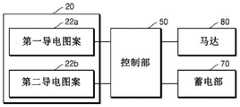
参照图1及图2,气溶胶生成装置的充电系统(以下“充电系统”)1000包括气 溶胶生成装置100和外部供电装置200。所述气溶胶生成装置100包括:加热器20, 施加电流时通过电阻发热;蓄电部70,向加热器20供电;以及控制部50,控制加热 器20。所述外部供电装置200包括:壳体210;充电容纳部220,可旋转地设置于壳 体210,以可拆卸地容纳气溶胶生成装置100;辅助蓄电装置230,存储将用于传递 至气溶胶生成装置100的电力;以及辅助供电装置240,控制辅助蓄电装置,向气溶 胶生成装置供电。1 and 2 , a charging system (hereinafter "charging system") 1000 of an aerosol generating device includes an
参照图2,气溶胶生成装置100包括:第一按钮部40,当要预热气溶胶生成装置 100时可按压;加热器20,施加电流时通过电阻发热;蓄电部70,能向所述加热器20瞬间提供高电力;以及控制部50,控制所述加热器20。所述加热器20加热容纳 于烟弹10的含有气溶胶生成物质的气化材料,以产生气溶胶,所述气溶胶生成物质 当加热到规定温度以上时发生气化。2, the
例如,当使用者操作第一按钮部40向控制部50传递激活信号时,蓄电部70允 许向加热器20供电,从而能够加热加热器20。相反,在加热器20被加热的过程中, 当使用者操作第一按钮部40时,控制部50被传递非激活信号以切断蓄电部70向加 热器20的供电。For example, when the user operates the
将用浸渍或表面涂有吸入物质的纸填充的卷烟形式的电子烟插入所述烟弹10时,所述加热器20被加热,以使卷烟部内部的吸入物质气化,使用者即可通过滤嘴 部吸入气化的吸入物质。When an electronic cigarette in the form of a cigarette filled with paper impregnated or coated with an inhalation substance is inserted into the
控制装置50在加热器20的电力不足而导致气溶胶生成装置100不能运行而需要充电的情况下,或者气溶胶生成装置100完成运行准备的情况下,驱动马达80以使 所述气溶胶生成装置100震动,使得使用者能够感知。When the power of the
另外,控制部50通过形成在气溶胶生成装置100中的第一显示部(未图示)显 示蓄电部70的剩余电量,即使在供给加热器20的电力不足而导致气溶胶生成装置 100不能运行的情况下,也可通过第一显示部显示蓄电部70的状态。In addition, the
蓄电部70在气溶胶生成装置100容纳于外部供电装置200的充电容纳部220的 状态下,能通过与充电容纳部220的充电端子223连接的气溶胶生成装置100的充电 端子30实现布线连接并接收供电,在气溶胶生成装置100接收供电时,控制部50 可通过第二显示部(未图示)显示供给到蓄电部70的电力。In the state where the
气溶胶生成装置100可通过充电端子30与外部供电装置200的充电端子223进 行数据通信。另外,气溶胶生成装置100可具备另设的无线通信端口。控制部50通 过引导设置在气溶胶生成装置100的无线通信端口和设置在外部供电装置200的无线 通信端口之间的通信,可与辅助供电装置240进行数据通信,从而能以无线的方式从 外部供电装置200接收供电。The
蓄电部70可从气溶胶生成装置100分离,可在外部供电装置200形成能容纳蓄 电部70的多个容纳部,以容纳一个或多个从气溶胶生成装置100分离的蓄电部70 并进行充电。The
另外,通过在气溶胶生成装置100内置将光能或机械能等外部能量转换为电能的发电手段,还可以自身产生电力并对蓄电部70进行充电。In addition, by incorporating in the aerosol generating device 100 a power generation means that converts external energy such as light energy or mechanical energy into electrical energy, it is also possible to generate electric power by itself and to charge the
图3是示意性示出图1所示的气溶胶生成装置的各结构的一部分的方框图,图4 是示出图1所示的气溶胶生成装置的一部分结构要素的立体图,图5是沿图4的IV-IV 线的剖视图。3 is a block diagram schematically showing a part of each configuration of the aerosol generating device shown in FIG. 1 , FIG. 4 is a perspective view showing a part of the components of the aerosol generating device shown in FIG. 1 , and FIG. 5 is a view along the 4. Sectional view of line IV-IV.
参照图3至图5,气溶胶生成装置100包括电子加热器20,所述电子加热器20 通过电发热,通过加热含有加热到规定温度以上时气化的气溶胶生成物质的气化材 料,产生气溶胶;所述电子加热器20包括:本体21,用于插入卷烟;第一导电图案 22a,设置于本体21的一部分,发挥加热卷烟的加热器和检测卷烟的温度的温度传感 器中一个的功能;第二导电图案22b,设置于本体21的另一部分,发挥加热器和温 度传感器中一个的功能;以及控制部50,控制第一导电图案22a和第二导电图案22b, 使第一导电图案22a和第二导电图案22b发挥加热器及温度传感器中一个的功能;第 一导电图案22a和第二导电图案22b分别与如蓄电部70等另设的供电部相连接。3 to 5 , the
本体21可由陶瓷原材料形成,但本发明的实施例不限于此。例如,本体21可包 含具有不容易导电、耐热、几乎不变形的特性的原材料。另外,本体21可形成为卷 烟插入时与卷烟最先接触的一侧端部呈锐角,但不限于此。例如,本体21只要可以 插入至卷烟的内部,则可具有任何形状。The
第一导电图案22a和第二导电图案22b包含电阻物质。例如,导电轨道可由金属 物质制作。作为另一例,导电轨道可由导电陶瓷物质、碳、金属合金或陶瓷物质和金 属的合成物质制作。The first
参照图5,以垂直于卷烟的长度方向截断的本体21的截面可以为直角四边形, 这是为了便于说明而例示的,本发明的实施例不限于此。即,以垂直于卷烟的长度方 向截断的本体21的截面可以为多边形,其中一个边可以以曲面形成,而且还可以以 圆形及椭圆形形成。这里,参照图6至图11说明以垂直于卷烟的长度方向截断的本 体21的截面为圆形的情况,为了说明上的便利,将以垂直于卷烟的长度方向截断的 本体21的截面为直角四边形的情况为主进行说明。Referring to FIG. 5 , the section of the
如上所述的以垂直于卷烟的长度方向截断的本体21的截面为直角四边形的情况下,如图4及图5所示,第一导电图案22a可设置在本体21的一面,第二导电图案 22b可设置在区别于一面的另一面。In the case where the cross section of the
控制部50可控制电子加热器20,以使第一导电图案22a发挥加热器的功能且第 二导电图案22b发挥温度传感器的功能。这是指第一导电图案22a和第二导电图案 22b中的一个发挥加热器的功能,另一个发挥温度传感器的功能。即,指如果第一导 电图案22a发挥温度传感器的功能,第二导电图案22b发挥加热器的功能。The
另外,为延长电子加热器20的寿命,控制部50可控制电子加热器20,以使第 一导电图案22a和第二导电图案22b相互交替地使其中一个发挥加热器的功能,另一 个发挥温度传感器的功能。In addition, in order to prolong the life of the
另外,当使用者按下气溶胶生成装置100的第一按钮部40使气溶胶生成装置100进入预热步骤时,由于电子加热器20需要瞬间高压,为电子加热器20的瞬间升温, 控制部50能够控制本体21的第一导电图案22a和第二导电图案22b,使两者均发挥 电子加热器20的功能,在气化温度保持步骤中,控制第一导电图案22a和第二导电 图案22b使其相互交替地使其中一个发挥加热器的功能,另一个发挥温度传感器的功 能。In addition, when the user presses the
另外,第一导电图案22a和第二导电图案22b中的一个以上可发挥通过测定热电阻来检测温度的温度传感器的功能。Moreover, one or more of the 1st
图6是示出图4所示的气溶胶生成装置的一部分结构要素的另一实施例的立体图,图7是沿图6的VI-VI线的剖视图。FIG. 6 is a perspective view showing another example of a part of the constituent elements of the aerosol generating device shown in FIG. 4 , and FIG. 7 is a cross-sectional view taken along line VI-VI of FIG. 6 .
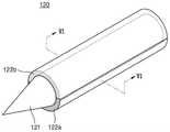
一方面,参照图6及图7,电子加热器120可包括:本体121,呈蜂针形状;第 一导电图案122a,设置在本体121的外周面的一部分;第二导电图案122b,设置在 本体121的外周面的另一部分;第一导电图案122a和第二导电图案122b分别与如蓄 电部70等另设的供电部相连接。On the one hand, referring to FIG. 6 and FIG. 7 , the
图8是示出图4所示的气溶胶生成装置的一部分结构要素的又一实施例的立体图,图9是沿图8的VIII-VIII线的剖视图。FIG. 8 is a perspective view showing still another example of some components of the aerosol generating device shown in FIG. 4 , and FIG. 9 is a cross-sectional view taken along line VIII-VIII in FIG. 8 .
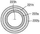
参照图8及图9,电子加热器220h,其特征在于,包括:本体221h,呈中空223h 的圆筒形状;第一导电图案222a,设置于本体221h的内周面;第二导电图案222b, 设置于本体221h的外周面;第一导电图案222a和第二导电图案222b分别与如蓄电 部70等另设的供电部相连接。8 and 9, the
例如,可在中空223h的内部插入卷烟。即,第一导电图案222a可与卷烟的外周 面接触。就具有这种结构的气溶胶生成装置100而言,当使用者将卷烟插入气溶胶生 成装置100并按下第一按钮部40使气溶胶生成装置100进入预热步骤时,为了急速 提高卷烟的温度,控制部50可控制成接触卷烟的第一导电图案222a和不接触电子烟 的第二导电图案222b均发挥电子加热器20的功能。For example, a cigarette can be inserted inside the hollow 223h. That is, the first
当然,在预热步骤中无需急速提高温度时,控制部50可控制成接触卷烟的第一 导电图案222a发挥加热器的功能,不接触卷烟的第二导电图案222b发挥温度传感器 的功能。另外,在气化温度保持步骤中,控制部50可控制成不接触卷烟的第二导电 图案222b发挥加热器的功能,接触电子烟的第一导电图案222a发挥温度传感器的功 能。Of course, when there is no need to rapidly increase the temperature in the preheating step, the
图10是示出图4所示的气溶胶生成装置的一部分结构要素的又一实施例的立体图,图11是沿图10的X-X线的剖视图。FIG. 10 is a perspective view showing still another example of some components of the aerosol generating device shown in FIG. 4 , and FIG. 11 is a cross-sectional view taken along line X-X of FIG. 10 .
参照图10及图11,电子加热器320包括:本体321,将中空323的圆筒沿圆周 方向分成多个分块;第一导电图案322a,设置在本体321的分块的内周面;第二导 电图案322b,设置在本体321的分块的外周面。10 and FIG. 11 , the
多个第一导电图案322a和第二导电图案322b分别与如蓄电部70等另设的供电 部相连接。控制部50控制电子加热器320,以控制第一导电图案322a发挥加热器的 功能,控制第二导电图案322b发挥温度传感器的功能。The plurality of first
另外,为了延长电子加热器320的寿命,控制部50可控制第一导电图案22a和 第二导电图案22b相互交替地发挥加热器和温度传感器的功能。In addition, in order to prolong the life of the
另外,当使用者按下气溶胶生成装置100的第一按钮部40使气溶胶生成装置100进入预热步骤时,由于电子加热器320需要瞬间高压,为了电子加热器320的瞬间升 温,控制部50控制成第一导电图案322a和第二导电图案322b均发挥加热器的功能。In addition, when the user presses the
另外,如果是在中空323的内部插入卷烟的结构的情况下,当使用者将卷烟插入气溶胶生成装置100并按下第一按钮部40使所述气溶胶生成装置100进入预热步骤 时,为急速提高卷烟的温度,控制部50控制成接触卷烟的第一导电图案322a发挥加 热器的功能,不接触电子烟的第二导电图案322b发挥温度传感器的功能。In addition, in the case of a structure in which a cigarette is inserted into the hollow 323, when the user inserts the cigarette into the
另外,在气化温度保持步骤中,控制部50控制成不接触卷烟的第二导电图案322b发挥加热器的功能,接触卷烟的第一导电图案322a发挥温度传感器的功能。In the vaporization temperature maintaining step, the
图12是示意性示出图1所示的气溶胶生成装置的各结构的一部分的方框图。FIG. 12 is a block diagram schematically showing a part of each configuration of the aerosol generating apparatus shown in FIG. 1 .
参照图12,气溶胶生成装置100包括:加热器20,施加电流时通过电阻发热; 蓄电部70,能向加热器20瞬间供给高电力;气化材料传感器90,检测是否安装了气 化材料;及控制部50,控制上述结构中的至少一个以上。12 , the
所述加热器20通过加热含有加热到规定温度以上时气化的物质(气化物质)的 气化材料,产生微细颗粒。The
根据气溶胶生成装置100的使用,控制部50通过预热步骤、气化温度达到步骤、 气化温度保持步骤来控制加热器20。The
例如,当使用者将用浸渍或表面涂有吸入物质的纸填充的卷烟形式的电子烟插入烟弹10,或者将液态的气化材料加入到烟弹10时,控制部50通过气化材料传感器 90检测气化材料,并通过控制加热器20预热气溶胶生成装置100使温度瞬间上升至 目标气化温度后,控制加热器20保持规定时间的气化温度。For example, when the user inserts an electronic cigarette in the form of a cigarette filled with paper impregnated or coated with an inhalation substance into the
如果在使用者按下气溶胶生成装置100的第一按钮部40的状态下,通过气化材 传感器90未检测到气化材料时,控制部50将加热器20仅运行到预热步骤,以防止 不必要的不正常运行,经过规定时间后,通过气化材传感器90还未检测到气化材料 时,控制蓄电部70切断向加热器20的供电,从而防止不必要的耗电。If no vaporized material is detected by the vaporized
气溶胶生成装置100可包括检测使用者的唇部接触的触控传感器91。因此,气 溶胶生成装置100不仅检测气化材料,还检测唇部的接触,从而使控制部50能够控 制气溶胶生成装置100的加热器20。The
例如,在使用者按下图2所示的气溶胶生成装置100的第一按钮部40的情况下, 控制部50通过控制加热器20预热气溶胶生成装置100,由触控传感器91检测到使 用者的唇部接触时,将加热器20的温度提升至目标气化温度后,控制加热器保持规 定时间的气化温度。即,分为预热步骤、气化温度达到步骤、气化温度保持步骤而进 行控制。For example, when the user presses the
如果在通过控制加热器20预热气溶胶生成装置100时间或设定的规定时间内, 未由触控传感器91检测到使用者的唇部接触,则控制部50通过控制蓄电部70切断 向加热器20的供电,以防止不必要的耗电。If the
另外,与是否发生气溶胶生成装置100的使用状态无关地,控制部50能基于剩 余电量判断是否为无需再充电也能运行的状态。如果是剩余电量为不进行再充电就不 能运行的状态,如上所述,气溶胶生成装置100能够通过外部供电部92接收来自外 部供电装置1000供电,该外部供电部92使气溶胶生成装置100能接收来自外部的供 电。因此,能够事先防止在使用者使用气溶胶生成装置100的过程中因电力耗尽而使 用被中断的情况。In addition, regardless of whether or not the
另外,从气溶胶生成装置的蓄电部70连接至加热器20的电子电路中的至少一部分可由单晶物质形成。存在于固体中的原子、离子、分子具有规则排列的物质称为单 晶物质,单晶物质具有整体内部原子排列有规律且完整的结构。根据存在于固体内的 原子、离子、分子的排列,即使是同类的固体,也可具有单晶结构或多晶结构。In addition, at least a part of the electronic circuit connected from the
单晶物质具有以下特征:低频率依赖性(low frequency dependence)、低电阻率(low resistivity)、高表面稳定性(hardly oxidized-抗氧化特性)、低晶界氧化特性(nograin boundary scattering)及高吸附性(high adhesion)。尤其,即使是同类的固体, 由于具有单晶结构时的电阻率小于具有多晶结构时的电阻率,例如,电子电路的布线 形成为单晶结构的固体的情况下,能减少布线的发热量,从而能够迅速地提升连接于 电子电路的电阻加热器的温度。Single-crystal substances have the following characteristics: low frequency dependence, low resistivity, high surface stability (hardly oxidized-antioxidation properties), low grain boundary scattering properties (nograin boundary scattering), and high Adsorption (high adhesion). In particular, even if it is a solid of the same type, the resistivity when it has a single crystal structure is lower than that when it has a polycrystalline structure. For example, when the wiring of an electronic circuit is formed of a solid of the single crystal structure, the heat generation amount of the wiring can be reduced. , so that the temperature of the resistance heater connected to the electronic circuit can be rapidly increased.
加热器20通过在规定温度以上加热容纳于烟弹10的卷烟,能够产生微细颗粒。 通常,当加热器20在200至400℃温度范围加热卷烟时,从卷烟产生微细颗粒,因 此,需要气溶胶生成装置从蓄电部70将瞬间高电力供给到加热器20,以使加热器20 的温度急速上升。例如,需要在气溶胶生成装置的运行开始后的1秒、2秒、3秒或 4秒之内,使加热器20的温度急速上升,使容纳于烟弹10中的卷烟在200至400℃ 温度范围被加热。The
为此,连接蓄电部70和加热器20的电子电路中的至少一部分可由单晶物质形成。构成电子电路的布线的至少一部分由单晶物质形成时,由于单晶物质的电阻率小,可 减少布线的发热量,因此,可将连接于电子电路的加热器20的温度急速提升至所需 温度。即,通过将构成电子电路的布线以小电阻率的单晶物质形成,能够较快地提升 加热器20的温度,以使卷烟在已设定的温度范围内被加热,从而能够改善气溶胶生 成装置的电力效率。For this reason, at least a part of the electronic circuit connecting the
在一实施例中,单晶物质可以是以由金、铜、银、铝、镍构成的组中的任一种金 属培养的单晶物质。优选地,单晶物质可以为单晶铜(Cu)。然而,单晶物质的种类 不限于此。In one embodiment, the single crystal material may be a single crystal material grown with any metal from the group consisting of gold, copper, silver, aluminum, nickel. Preferably, the single crystal substance may be single crystal copper (Cu). However, the kind of single crystal substance is not limited to this.
另外,单晶物质可由铸块(ingot)形状及薄膜形状中至少一种形状形成。例如, 将以铸块形状培养的单晶物质截断为板状的分块后,可利用截断的板状分块来形成电 子电路的布线。In addition, the single crystal substance may be formed of at least one of an ingot shape and a thin film shape. For example, after a single crystal substance grown in the shape of an ingot is cut into plate-shaped segments, the cut plate-shaped segments can be used to form wirings for electronic circuits.
图13是示意性示出图12所示的气溶胶生成装置的加热器的细部结构的剖视图。13 is a cross-sectional view schematically showing a detailed structure of a heater of the aerosol generating device shown in FIG. 12 .
参照图13,本发明一实施例的棒形状的电加热式吸烟机的加热器420包括:陶 瓷棒421,具有尖端;第一保护层422,包围陶瓷棒421;电路基板423,缠绕于第一 保护层422上,且印刷有包括加热器420的电极图案的电极图案423a、423b;第二 保护层424,包围电路基板423;玻璃膜保护涂层425,形成在覆盖有第二保护层424 的结合体上;凸缘426,结合于形成有玻璃膜保护涂层425的结合体上;以及防污涂 层427,形成在最外层。13 , the
陶瓷棒421被加工成适当的长度和直径,用于提供加热器能穿过卷烟的刚性。陶瓷棒421被加工后,为了使印刷有电阻的电路基板423的附着性最大,且为了防止陶 瓷棒421上发生裂纹,在陶瓷棒421的外周形成第一保护层422。第一保护层422可 通过附着保护膜或实施玻璃膜涂层来形成。在第一保护层422上附着印刷有电阻的电 路基板423。电路基板423的两面印刷电极图案423a、423b,在内侧面印刷加热器电 极图案423a,在外侧面印刷传感器电极图案423b。利用丝网方式或喷墨打印的方式 来印刷电路基板423的电极图案423a、423b。The
图14是示出图13的加热器所具备的电阻双面印刷电路基板的制造方法的概念图。FIG. 14 is a conceptual diagram illustrating a method of manufacturing a resistance double-sided printed circuit board included in the heater of FIG. 13 .
参照图14,首先,制造陶瓷电路基板并将其截断后,在一面上印刷加热器电极 图案423a,在另一面上印刷传感器电极图案423b。将如上所述那样在两面印刷有电 极的电路基板423缠绕于形成在陶瓷棒421上的第一保护层422外侧。印刷图案423a、 423b的原材料优选由选自Ni、Pt、W、Mo、W-Mo合金、镍铬铁(Nichrome)系合 金、铬铝钴(Kanthal)系合金及不锈钢中的一个以上构成。Referring to Fig. 14, first, after manufacturing and cutting a ceramic circuit board, a
此时,用于传感器电极图案423b的电极物质优选具有比用于加热器电极图案423a的电极物质更高的抗温系数。另外,在电路基板423外侧形成第二保护层424, 以保护印刷在电路基板423的电极图案423b。第二保护层424也可通过实施玻璃膜 涂层或缠绕保护膜来形成。At this time, the electrode material used for the
这样,在陶瓷棒421上依次附着或形成第一保护层422、电路基板423及第二保 护层424后,执行电路基板423和电极图案423a、423b的烧结。然后,进行一次外 观检查及电极图案423a、423b的电阻检查。下面,将在陶瓷棒421依次附着第一保 护层422、电路基板423及第二保护层424后,实施了电路基板423和电极图案423a、423b的烧结而成的结合体,称之为陶瓷棒结合体。In this way, after the first
图15是示意性示出图13的加热器所具备的陶瓷棒结合体的剖视图。FIG. 15 is a cross-sectional view schematically showing a ceramic rod assembly included in the heater of FIG. 13 .
参照图15,为使加热器易于插入卷烟内侧,优选使陶瓷棒结合体150的越靠外 侧的层的长度越短,以在陶瓷棒的尖端侧构成阶梯形状。陶瓷棒结合体150与凸缘 426相结合,该凸缘426用于使加热器的设置变简单。Referring to Fig. 15, in order to facilitate the insertion of the heater inside the cigarette, the length of the outer layer of the
参照图13,结合凸缘426后,可形成覆盖陶瓷棒结合体150的玻璃膜保护涂层 425,以使具有阶梯形状的陶瓷棒结合体150的外观更加平缓并光滑。更详细而言, 玻璃膜保护涂层425覆盖露出的陶瓷棒421的尖端和第一保护层422的尖端侧一部 分、电路基板423的尖端侧一部分及第二保护层424整体。玻璃膜保护涂层425使加 热器顺畅地插入至卷烟内的同时,可防止由多层的薄膜或涂层形成的加热器的层被剥 离。13, after the
另外,陶瓷加热器的最外侧,即,玻璃膜保护涂层425的外部还可形成防污涂层427。为了形成防污涂层427而使用的物质,优选包含SiO2、Si3N4、BN等纳米陶瓷 颗粒。In addition, an antifouling coating 427 may also be formed on the outermost side of the ceramic heater, that is, outside the glass film
一方面,电路基板423的电极图案423a、423b包括锡焊板(未图示),所述锡焊 板用于连接用来施加外部电源的桥丝510、520、530。锡焊板(未图示)优选位于电 路基板423的一端部,以使能够容易实现桥丝510、520、530的连接,此时的一端部 并非陶瓷棒421的尖端部,而是尖端部的相反侧的端部,即,下端部(附图中为右侧)。 凸缘426在与陶瓷棒结合体150相结合时位于比电路基板423的锡焊板更靠上侧的位 置,因此,当加热器插入卷烟内部时,连接于锡焊板(未图示)的桥丝510、520、 530被凸缘426阻挡,从而不会插入卷烟内而被保护。On the one hand, the
图16是示出图13的加热器上连接有两个桥丝的状态的概念图。FIG. 16 is a conceptual diagram showing a state in which two bridge wires are connected to the heater of FIG. 13 .
参照图16,加热器连接两个桥丝510'、520'的情况为,形成于电路基板423的电 极图案423a、423b仅包括加热器的情况。桥丝510'、520'分别连接至电源的正极和负 极。Referring to Fig. 16 , the case where the heater is connected to the two bridge wires 510', 520' is a case where the
图17是示出图13的加热器上连接有三个桥丝的状态的概念图。FIG. 17 is a conceptual diagram showing a state in which three bridge wires are connected to the heater of FIG. 13 .
参照图17,加热器上连接有三个桥丝510'、520'、530的情况为如下情况:形成 于电路基板423(参照图4)的电极图案423a、423b(参照图4)分别包括加热器电 极图案423a(参照图4)和传感器电极图案423b(参照图4)。三个桥丝510'、520'、530分别为与加热器电极图案423a(参照图4)相连接的桥丝510'、与传感器电极图 案423b(参照图4)相连接的桥丝520'及接地的桥丝530。Referring to FIG. 17 , the case where three
图18是示出图13的加热器上连接有四个桥丝的状态的概念图。FIG. 18 is a conceptual diagram showing a state in which four bridge wires are connected to the heater of FIG. 13 .
参照图18,加热器上连接有四个桥丝512、514、522、524的情况为如下情况: 形成于电路基板423(参照图4)的电极图案423a、423b(参照图4)分别包括加热 器电极图案423a(参照图4)和传感器电极图案423b(参照图4)。四个桥丝512、 514、522、524分别为与加热器电极图案423a(参照图4)相连接的正极、负极的桥 丝512、514、与传感器电极图案423b(参照图4)相连接的正极、负极的桥丝522、 524。Referring to FIG. 18, the case where four
优选桥丝410、420、430、510'、520'、512、514、522、524的原材料由选自Ni、 Pt、W、Al、Ag、Au、铬铝钴(Kanthal)系合金、不锈钢中的一种以上组成。Preferably, the raw materials of the
图19是示出图1所示的充电系统的第一运行例的概念图。FIG. 19 is a conceptual diagram showing a first operation example of the charging system shown in FIG. 1 .
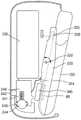
参照图19,外部供电装置200具备可分离的各壳体210,所述各壳体210的内部 被划分形成,以能够安装外部供电装置200的结构要素,由于具备有多个卡扣211和 卡槽212,外部供电装置200是使壳体210能够互相结合的结构。Referring to FIG. 19 , the external
充电容纳部220可旋转地设置在壳体210,并以可装卸的方式容纳气溶胶生成装置100。充电容纳部220通过形成在两侧面的孔221设置铰链222,通过将铰链222 插入形成在壳体210内部的凹槽214,可设置成能够相对于壳体210旋转。The charging
另外,为了稳定地容纳气溶胶生成装置100,与气溶胶生成装置100面对面的充 电容纳部220的一侧可形成为与气溶胶生成装置100的外形相同的形状。并且,辅助 蓄电装置230和辅助供电装置通过布线连接,辅助供电装置240与形成在所述充电容 纳部220的充电端子223通过布线连接。In addition, in order to stably accommodate the
辅助蓄电装置230存储将用于传递至气溶胶生成装置100的电力,辅助供电装置240通过控制辅助蓄电装置230向气溶胶生成装置100供电。辅助蓄电装置230和辅 助供电装置240可安装于外部供电装置200的容纳部213。The auxiliary
所述辅助供电装置240以通过如USB端口242等内置于壳体的通常的外部电源 能够对辅助蓄电装置230进行充电的方式进行控制,并通过LED241显示辅助蓄电装 置230的充电状态。The auxiliary
例如,LED241分别具备三个LED,可根据充电量点亮一个LED或两个或三个LED,当点亮三个LED时,可表示辅助蓄电装置230已被充电至最高值的状态。For example, each of the
LED241的各LED可通过设置在另一壳体210的孔215向壳体外部点亮LED241, 该另一壳体210与安装有LED241的壳体210相结合。另外,壳体210内部设置有通 过孔216向壳体10外部伸出的第二按钮部243,第二按钮部243在壳体210内通过 固定突起244被支撑。Each LED of the
第二按钮部243通过布线与辅助供电装置240相连接,当使用者操作第二按钮部243时,可通过向辅助供电装置240传递激活信号来允许辅助蓄电装置230向所述气 溶胶生成装置100供电,另外,在辅助蓄电装置230向气溶胶生成装置100供电的过 程中,当使用者再次操作第二按钮部243时,还可切断辅助蓄电装置230向所述气溶 胶生成装置100的供电。The
例如,如图19所示,在将气溶胶生成装置100附着于充电容纳部220,且使充 电容纳部220与壳体210的长度方向相平行的状态下,当使用者按下第二按钮部243 时,辅助供电装置240能够以如下的清洁模式运行:通过允许辅助蓄电装置230向气 溶胶生成装置100供电,溶解粘在气溶胶生成装置100的灰或异物,以清洁气溶胶生 成装置100。For example, as shown in FIG. 19 , in a state where the
具体而言,使用者操作第二按钮部243的信号,从辅助供电装置240通过布线经 过充电容纳部220的充电端子223及气溶胶生成装置100的充电端子30,传递至气 溶胶生成装置100的控制部50,从而使气溶胶生成装置100的加热器20运行。Specifically, the signal of the user operating the
这表示,在将气溶胶生成装置100安装于充电容纳部220,且使充电容纳部220 与壳体210的长度方向相平行的状态下,即使不用另外操作气溶胶生成装置100的第 一按钮部40,也可通过操作外部供电装置200的第二按钮部243来使气溶胶生成装 置100的加热器20运行。This means that in a state where the
图20是示出图1所示的充电系统的第二运行例的概念图,图21是示出图1所示 的充电系统的第三运行例的概念图。Fig. 20 is a conceptual diagram showing a second operation example of the charging system shown in Fig. 1 , and Fig. 21 is a conceptual diagram showing a third operation example of the charging system shown in Fig. 1 .
一方面,参照图20,在将气溶胶生成装置100附着于充电容纳部220,且使充电 容纳部220与壳体210的长度方向相交叉的状态下,当使用者按下第二按钮部243 时,辅助供电装置240能够以如下的预热模式运行:通过允许辅助蓄电装置230向气 溶胶生成装置100供电,预热气溶胶生成装置100。On the one hand, referring to FIG. 20 , in a state where the
即,设置在充电容纳部220的充电端子223在气溶胶生成装置100容纳于充电容 纳部220的状态下与充电端子30相连接,所述充电端子30与充电端子223以面对面 的方式设置于气溶胶生成装置100,通过辅助供电装置240的控制,可将充电到辅助 蓄电装置230的电力供给至气溶胶生成装置100。辅助供电装置240具备无线通信端 口,因此不仅能通过有线方式而且也能通过无线方式直接向气溶胶生成装置100供 电。That is, the charging
例如,当使用者操作第二按钮部243并向辅助供电装置240传递激活信号时,允 许辅助蓄电装置230向气溶胶生成装置100供电,从而能够加热气溶胶生成装置100 的加热器20。相反,在加热加热器20的过程中使用者操作第二按钮部243时,辅助 供电装置240接收非激活信号,从而能够切断辅助蓄电装置230向气溶胶生成装置 100的供电。For example, when the user operates the
另外,在壳体210上设置有第一磁体250和第二磁体260,该第一磁体250和第 二磁体260以充电容纳部220的旋转中心,即以铰链222的中心以面对面的方式设置。 并且,充电容纳部220包括与第一磁体250及第二磁体260中的一个面对面的第三磁 体225。虽然,附图中示出了第三磁体225与第一磁体250面对面地设置的情况,但 本发明的实施例不限于此,第三磁体225也可与第二磁体260面对面地设置在充电容 纳部220的下端。然而,以下,为了便于说明,将以第三磁体225与第一磁体250 面对面地设置于充电容纳部220的上端的情况为主进行说明。In addition, a
另外,第一磁体250及第二磁体260中一个可倾斜于壳体210的长度方而设置于 壳体210。虽然附图中示出了设置于外部供电装置200的下侧的第二磁体260倾斜于 壳体210的长度方向而设置于壳体210,但本发明的实施例不限于此,第一磁体250 也可倾斜于壳体210的长度方向而设置于壳体210。然而,以下,为了便于说明,将 以第二磁体260倾斜于壳体210的长度方向设置在壳体210的情况为主进行说明。In addition, one of the
另外,气溶胶生成装置100可包括第四磁体60,该第四磁体60与第一磁体250 及第二磁体260中的不与第三磁体225面对面的另一磁体面对面。In addition, the
简要说明上述结构,在外部供电装置200的壳体210的上端和下端分别设置有第一磁体250和第二磁体260,充电容纳部220的上端设置有与第一磁体250面对面的 第三磁体225,在气溶胶生成装置100的下端设置有与第二磁体260面对面的第四磁 体60。Briefly describing the above structure, the upper and lower ends of the
在此,在第一磁体250与第三磁体225之间、第一磁体250与第四磁体60之间、 第二磁体260与第三磁体225之间、第二磁体260与第四磁体60之间可分别存在引 力作用。Here, between the
因此,根据如上所述的结构,将气溶胶生成装置100安装于充电容纳部220,且 由使用者对气溶胶生成装置100的上端加压时,由于第一磁体250与第三磁体225 之间形成的引力,如图3(19?)所示,充电容纳部220可以与壳体210的长度方向 相平行的方式设置。Therefore, according to the above structure, when the
一方面,如图10(19?)所示,在气溶胶生成装置100安装于充电容纳部220 的状态下,当使用者以克服在第一磁体250与第三磁体225之间形成的引力的力对气 溶胶生成装置100的下端加压时,如图11(20?)所示,充电容纳部220顺时针旋 转,最终因在第二磁体260与第四磁体60之间形成的引力,充电容纳部220可以与 壳体210的长度方向相交叉的方式设置。On the one hand, as shown in FIG. 10 (19?), in the state where the
此时,如上所述,由于第二磁体260可倾斜于壳体210的长度方向而设置于壳体210,因此,气溶胶生成装置100可在外部供电装置200内倾斜(tilt)以对应于第二 磁体260的倾斜角。At this time, as described above, since the
之后,使用者向倾斜状态的气溶胶生成装置100施加力,并以能够克服第二磁体260与第四磁体60之间引力的力对气溶胶生成装置100施加力,则如图12所示,能 够从外部供电装置200分离气溶胶生成装置100。After that, the user applies force to the
图22是示出图1所示的气溶胶生成装置可在容纳于外部供电装置的状态下使用的状态的分解立体图。FIG. 22 is an exploded perspective view showing a state in which the aerosol generating device shown in FIG. 1 can be used while being accommodated in an external power supply device.
参照图22,气溶胶生成装置100可容纳于外部供电装置200的充电容纳部220 并接收电力供给。当使用者欲使用气溶胶生成装置100时,在气溶胶生成装置100 通过第四磁体60容纳于外部供电装置200的充电容纳部220的状态下推压气溶胶生 成装置100的下端部时,则在气溶胶生成装置100通过其具备的第四磁体60容纳于 充电容纳部220的状态下,使充电容纳部220紧贴于设置在壳体210并以规定角度倾 斜的第二磁体260。22 , the
通过这种操作,气溶胶生成装置100以规定角度倾斜于壳体210外部的状态使气溶胶生成装置100的上部一部分向外部伸出,使用者在向外部伸出的气溶胶生成装置 100的烟弹10中插入卷烟,并按下外部供电装置200的第二按钮部243即可预热气 溶胶生成装置100。By this operation, the
因此,气溶胶生成装置100可在从充电系统1000接收电力供给的状态下不中断 吸入而连续使用。Therefore, the
图23是示出图1所示的气溶胶生成装置从外部供电装置分离的过程的立体图。FIG. 23 is a perspective view showing a process in which the aerosol generating device shown in FIG. 1 is separated from the external power supply device.
参照图23,当使用者将气溶胶生成装置100从外部供电装置200分离时,如上 所述那样,气溶胶生成装置100倾斜于外部供电装置200且一部分被伸出的状态下, 向气溶胶生成装置100施加规定的力,从而可克服气溶胶生成装置100和外部供电装 置200的磁力并伸出。23 , when the user separates the
本发明不限于上述的特定优选实施例,在不脱离由所附权利要求书的要求保护的本发明的主旨的情况下,本领域技术人员可实施各种变型,并且这些变更属于权利要 求书记载的范围内。The present invention is not limited to the specific preferred embodiments described above, and various modifications may be implemented by those skilled in the art without departing from the gist of the present invention as claimed in the appended claims, and such modifications belong to the description of the claims. In the range.
另外,本说明书中,“部”可以为处理器或电路等硬件结构(hardware component),及/或由处理器等结构执行的软件结构(software component)。In addition, in this specification, a "section" may be a hardware component (hardware component) such as a processor or a circuit, and/or a software component (software component) executed by a structure such as a processor.
上述的本说明书的说明用于示例,本说明书内容所属技术领域的专业技术人员应理解,在不变更本发明的技术思想或必要特征的情况下,也可变形为其他具体形式。 因此,应理解,上述实施例在所有方面上仅仅是示例,而并非用于限制本发明。例如, 以统合说明的各结构要素可分散实施,同样,被分散说明的结构要素也可以结合的形 式实施。The above descriptions in this specification are for examples, and those skilled in the art to which the content of this specification pertains should understand that other specific forms may be modified without changing the technical idea or essential features of the present invention. Therefore, it should be understood that the above-described embodiments are only examples in all respects, and are not intended to limit the present invention. For example, each of the structural elements described in an integrated manner can be implemented in a distributed manner, and similarly, the structural elements described in a distributed manner can also be implemented in a combined form.
本实施例的范围由所附权利要求书确定而非具体实施方式确定,并且应被解释为包括从权利要求书的含义、范围及其等同概念得出的所有变更或变形的方式。The scope of the present embodiment is determined by the appended claims rather than the detailed description, and should be construed to include all changes or modifications derived from the meaning, scope and equivalent concepts of the claims.
以上,参考附图所示的一实施例对本发明进行了说明,但其仅为例示,本领域技术人员可理解,可进行多种变形及实施例的变形。因此,本发明真正的技术保护范围 应由所附权利要求书的技术思想确定。The present invention has been described above with reference to an embodiment shown in the accompanying drawings, but this is merely an example, and those skilled in the art can understand that various modifications and modifications of the embodiments are possible. Therefore, the true technical protection scope of the present invention should be determined by the technical idea of the appended claims.
产业上的可利用性Industrial Availability
如上所述,本发明实施例的气溶胶生成装置、其控制方法以及包括该装置的充电系统,可实现不需要燃烧也可使气溶胶形成物质气化的气溶胶生成装置。As described above, the aerosol generating device, the control method thereof, and the charging system including the device according to the embodiments of the present invention can realize the aerosol generating device that can vaporize the aerosol-forming substance without burning.
Claims (30)
Translated fromChineseApplications Claiming Priority (18)
| Application Number | Priority Date | Filing Date | Title |
|---|---|---|---|
| KR20170008904 | 2017-01-18 | ||
| KR20170008901 | 2017-01-18 | ||
| KR20170008905 | 2017-01-18 | ||
| KR10-2017-0008905 | 2017-01-18 | ||
| KR10-2017-0008901 | 2017-01-18 | ||
| KR10-2017-0008904 | 2017-01-18 | ||
| KR1020170058776AKR20180085648A (en) | 2017-01-18 | 2017-05-11 | Power-efficient fine particle generator |
| KR10-2017-0058776 | 2017-05-11 | ||
| KR10-2017-0058772 | 2017-05-11 | ||
| KR1020170058772AKR20180085646A (en) | 2017-01-18 | 2017-05-11 | A fine particle generator having a temperature sensor |
| KR1020170058775AKR20180085340A (en) | 2017-01-18 | 2017-05-11 | A fine particle generator having various power supply means |
| KR10-2017-0058775 | 2017-05-11 | ||
| KR10-2017-0146951 | 2017-06-11 | ||
| KR20170146951 | 2017-11-06 | ||
| KR10-2017-0161440 | 2017-11-29 | ||
| KR1020170161440AKR101987235B1 (en) | 2017-01-18 | 2017-11-29 | Heater of electric heating smoking apparatus |
| CN201880007262.7ACN110198642A (en) | 2017-01-18 | 2018-01-18 | Aerosol generating device, control method thereof and charging system comprising device |
| PCT/KR2018/000871WO2018135888A1 (en) | 2017-01-18 | 2018-01-18 | Aerosol generating device, method for controlling same, and charging system including same |
Related Parent Applications (1)
| Application Number | Title | Priority Date | Filing Date |
|---|---|---|---|
| CN201880007262.7ADivisionCN110198642A (en) | 2017-01-18 | 2018-01-18 | Aerosol generating device, control method thereof and charging system comprising device |
Publications (1)
| Publication Number | Publication Date |
|---|---|
| CN114711472Atrue CN114711472A (en) | 2022-07-08 |
Family
ID=67751198
Family Applications (3)
| Application Number | Title | Priority Date | Filing Date |
|---|---|---|---|
| CN202010760946.3APendingCN111869939A (en) | 2017-01-18 | 2018-01-18 | Charging system |
| CN201880007262.7APendingCN110198642A (en) | 2017-01-18 | 2018-01-18 | Aerosol generating device, control method thereof and charging system comprising device |
| CN202111499276.5APendingCN114711472A (en) | 2017-01-18 | 2018-01-18 | Aerosol generating device, control method thereof and charging system comprising device |
Family Applications Before (2)
| Application Number | Title | Priority Date | Filing Date |
|---|---|---|---|
| CN202010760946.3APendingCN111869939A (en) | 2017-01-18 | 2018-01-18 | Charging system |
| CN201880007262.7APendingCN110198642A (en) | 2017-01-18 | 2018-01-18 | Aerosol generating device, control method thereof and charging system comprising device |
Country Status (4)
| Country | Link |
|---|---|
| US (4) | US11253003B2 (en) |
| EP (3) | EP3747288A1 (en) |
| JP (5) | JP6898048B2 (en) |
| CN (3) | CN111869939A (en) |
Families Citing this family (57)
| Publication number | Priority date | Publication date | Assignee | Title |
|---|---|---|---|---|
| CN111869939A (en)* | 2017-01-18 | 2020-11-03 | 韩国烟草人参公社 | Charging system |
| JP7597447B2 (en) | 2017-08-23 | 2024-12-10 | フィリップ・モーリス・プロダクツ・ソシエテ・アノニム | Aerosol generation system having a charging device and an aerosol generation device having a side coupling |
| CN207803449U (en)* | 2018-01-16 | 2018-09-04 | 东莞市国研电热材料有限公司 | A round rod-shaped ceramic heating element for electronic cigarettes |
| KR102342331B1 (en) | 2018-12-07 | 2021-12-22 | 주식회사 케이티앤지 | heater assembly for heating cigarette and aerosol generating device including thereof |
| KR102212378B1 (en) | 2019-01-03 | 2021-02-04 | 주식회사 케이티앤지 | Aerosol generating device conprising a voltage converter and method of controlling same |
| KR102219853B1 (en) | 2019-01-16 | 2021-02-24 | 주식회사 케이티앤지 | Method for controlling aerosol generating apparatus using multiple geomagnetic sensors and apparatus thereof |
| KR102253048B1 (en) | 2019-04-25 | 2021-05-17 | 주식회사 케이티앤지 | Recharging system for aerosol generating apparatus |
| KR102252454B1 (en)* | 2019-05-09 | 2021-05-14 | 주식회사 케이티앤지 | Aerosol generating device and operation method thereof |
| KR102281869B1 (en) | 2019-06-18 | 2021-07-26 | 주식회사 케이티앤지 | Aerosol generating device and operation method thereof |
| KR102392126B1 (en)* | 2019-08-02 | 2022-04-28 | 주식회사 케이티앤지 | Heating assembly, aerosol generating device and system comprising the same |
| KR102400048B1 (en)* | 2019-09-25 | 2022-05-19 | 주식회사 케이티앤지 | Aerosol generating device and control method thereof |
| KR102412118B1 (en)* | 2019-10-10 | 2022-06-22 | 주식회사 케이티앤지 | Aerosol generating device and operation method thereof |
| CN113576048A (en)* | 2020-04-30 | 2021-11-02 | 深圳市合元科技有限公司 | Susceptor for aerosol-generating device, aerosol-generating device |
| JP6682033B1 (en) | 2019-11-05 | 2020-04-15 | 日本たばこ産業株式会社 | Power supply unit for aerosol inhalers |
| JP6706712B1 (en) | 2019-11-05 | 2020-06-10 | 日本たばこ産業株式会社 | Power supply unit for aerosol inhalers |
| KR102431330B1 (en) | 2019-11-12 | 2022-08-10 | 주식회사 케이티앤지 | Aerosol generating device and operation method thereof |
| JP7636411B2 (en)* | 2019-11-28 | 2025-02-26 | ジェイティー インターナショナル エスエイ | Aerosol generating device, controller for aerosol generating device, and method for controlling aerosol generating device |
| CN211910549U (en)* | 2020-01-10 | 2020-11-13 | 深圳市合元科技有限公司 | Aerosol generating device |
| CN211672480U (en)* | 2020-01-17 | 2020-10-16 | 常州市派腾电子技术服务有限公司 | Charging device and aerosol generating device set with same |
| KR102402064B1 (en)* | 2020-01-31 | 2022-05-24 | 주식회사 케이티앤지 | Aerosol-generating apparatus with reduced pre-heating time |
| KR102337231B1 (en)* | 2020-02-07 | 2021-12-08 | 주식회사 케이티앤지 | An aerosol generating device and a method for controlling thereof |
| KR102397448B1 (en) | 2020-02-07 | 2022-05-12 | 주식회사 케이티앤지 | Heater for aerosol generating device |
| JP7260712B2 (en)* | 2020-03-18 | 2023-04-18 | 日本たばこ産業株式会社 | Control device, control method, and program |
| KR102432917B1 (en) | 2020-03-30 | 2022-08-16 | 주식회사 케이티앤지 | Aerosol generating device that activates heater by detecting user's contact and method for operating the same |
| KR102457773B1 (en)* | 2020-05-22 | 2022-10-21 | 주식회사 케이티앤지 | Aerosol generating apparatus, method for operating the same and cartridge used for the same |
| CN112369694A (en)* | 2020-06-19 | 2021-02-19 | 湖北中烟工业有限责任公司 | Heating assembly for smoking device |
| EP3962234A1 (en)* | 2020-08-27 | 2022-03-02 | Heraeus Nexensos GmbH | Flexible heating element, method for manufacturing such a heating element and use of a flexible heating element |
| JP6856811B1 (en) | 2020-09-07 | 2021-04-14 | 日本たばこ産業株式会社 | Power supply unit of aerosol generator |
| JP6905134B1 (en) | 2020-09-07 | 2021-07-21 | 日本たばこ産業株式会社 | Power supply unit of aerosol generator |
| JP6856810B1 (en)* | 2020-09-07 | 2021-04-14 | 日本たばこ産業株式会社 | Power supply unit of aerosol generator |
| CN112244359B (en)* | 2020-09-30 | 2024-08-09 | 深圳麦时科技有限公司 | Heating element, heating assembly and heating device |
| GB2604976B (en)* | 2020-12-01 | 2025-08-13 | Em Tech Co Ltd | Heater for microparticle generator and installation structure thereof |
| CN112869238A (en)* | 2021-01-20 | 2021-06-01 | 昆明理工大学 | Temperature control method for sheet type center heating cigarette |
| IT202100005417A1 (en)* | 2021-03-09 | 2021-06-09 | Marco Manganiello | ADDITIONAL POWER SUPPLY DEVICE |
| KR102640829B1 (en)* | 2021-03-29 | 2024-02-23 | 주식회사 케이티앤지 | Heater for aerosol-generating apparatus and aerosol-generating apparatus including the same |
| CN117396094A (en)* | 2021-06-28 | 2024-01-12 | 日本烟草产业株式会社 | aerosol generation system |
| EP4321045A4 (en)* | 2021-06-28 | 2025-03-12 | Japan Tobacco Inc. | AEROSOL GENERATION SYSTEM |
| EP4321044A4 (en)* | 2021-06-28 | 2025-03-12 | Japan Tobacco Inc. | AEROSOL GENERATION SYSTEM |
| WO2023275951A1 (en)* | 2021-06-28 | 2023-01-05 | 日本たばこ産業株式会社 | Aerosol generation system |
| CN115701331A (en)* | 2021-08-02 | 2023-02-10 | 深圳市合元科技有限公司 | Aerosol generating system and aerosol generating device |
| CN116138505A (en)* | 2021-11-22 | 2023-05-23 | 贵州中烟工业有限责任公司 | A smokeable material heating device and heating method thereof |
| JPWO2023105668A1 (en)* | 2021-12-08 | 2023-06-15 | ||
| CN114223963A (en)* | 2021-12-24 | 2022-03-25 | 重庆江陶科技有限公司 | Resistive heater and aerosol generating device for aerosol generating device |
| CN116509063A (en)* | 2022-01-24 | 2023-08-01 | 深圳市合元科技有限公司 | Aerosol generating device and heater for aerosol generating device |
| JP7698075B2 (en)* | 2022-02-08 | 2025-06-24 | ケーティー アンド ジー コーポレイション | Electronic device and charging system including same |
| JP2023149778A (en)* | 2022-03-31 | 2023-10-13 | サミー株式会社 | Game machine |
| GB202206349D0 (en)* | 2022-04-29 | 2022-06-15 | Nicoventures Trading Ltd | Aerosol provision system |
| EP4518703A1 (en)* | 2022-05-03 | 2025-03-12 | JT International S.A. | Aerosol generating device comprising a heat diffusion layer |
| CN115349673A (en)* | 2022-08-08 | 2022-11-18 | 海南摩尔兄弟科技有限公司 | Aerosol generating device and its heating components |
| CN120322169A (en)* | 2022-12-16 | 2025-07-15 | 日本烟草产业株式会社 | Aerosol generating system and information processing method |
| WO2024136168A1 (en)* | 2022-12-20 | 2024-06-27 | Kt&G Corporation | Aerosol generating device |
| US20240237740A1 (en)* | 2023-01-12 | 2024-07-18 | N2B Limited | Smoking device with needle electrodes |
| DE102023104390A1 (en)* | 2023-02-22 | 2024-08-22 | Innovative Sensor Technology Ist Ag | Aerosol generating device |
| WO2025095303A1 (en)* | 2023-10-31 | 2025-05-08 | 주식회사 케이티앤지 | Aerosol-generating apparatus |
| WO2025105660A1 (en)* | 2023-11-15 | 2025-05-22 | 주식회사 케이티앤지 | Aerosol-generating apparatus |
| CN117470384B (en)* | 2023-12-04 | 2024-08-13 | 深圳市鑫鸿佳科技有限公司 | Real-time temperature detection device and detection method for heating sheet of electronic cigarette |
| CN222129361U (en)* | 2024-01-15 | 2024-12-10 | 深圳麦克韦尔科技有限公司 | Aerosol generating device |
Citations (5)
| Publication number | Priority date | Publication date | Assignee | Title |
|---|---|---|---|---|
| EP0503767A1 (en)* | 1991-03-11 | 1992-09-16 | Philip Morris Products Inc. | Flavor generating article |
| US20150020832A1 (en)* | 2012-01-03 | 2015-01-22 | Philip Morris Products S.A. | Aerosol-generating device and system |
| KR20150004227U (en)* | 2014-05-16 | 2015-11-25 | 석인선 | slide eletronic cigarette |
| US20160150824A1 (en)* | 2014-02-28 | 2016-06-02 | Beyond Twenty Ltd. | E-cigarette personal vaporizer |
| CN105939625A (en)* | 2014-02-10 | 2016-09-14 | 菲利普莫里斯生产公司 | Aerosol generating system with heater assembly and cartridge for an aerosol generating system with fluid permeable heater assembly |
Family Cites Families (68)
| Publication number | Priority date | Publication date | Assignee | Title |
|---|---|---|---|---|
| US4383564A (en)* | 1980-12-01 | 1983-05-17 | Hoie Karl H | Collapsible, portable, open-top container for liquid, preferably |
| US4771936A (en)* | 1987-08-20 | 1988-09-20 | Dolby Timothy S | Box top lid |
| US5249586A (en) | 1991-03-11 | 1993-10-05 | Philip Morris Incorporated | Electrical smoking |
| US5665262A (en)* | 1991-03-11 | 1997-09-09 | Philip Morris Incorporated | Tubular heater for use in an electrical smoking article |
| JPH05114460A (en)* | 1991-10-21 | 1993-05-07 | Chichibu Cement Co Ltd | Heating apparatus |
| JPH0640257U (en)* | 1992-10-28 | 1994-05-27 | 清 杉山 | Metal fittings that stop the door with the force of a magnet |
| JPH09278197A (en)* | 1996-04-09 | 1997-10-28 | Canon Inc | Sheet processing equipment |
| CN100381083C (en)* | 2003-04-29 | 2008-04-16 | 韩力 | Non-combustible electronic spray cigarette |
| KR100636287B1 (en) | 2005-07-29 | 2006-10-19 | 주식회사 케이티앤지 | Electric Cigarette Heaters |
| CN1991654B (en)* | 2005-12-31 | 2013-05-22 | 博奥生物有限公司 | Precise heating temperature control device and method without temperature sensor |
| JP2011087569A (en)* | 2009-05-15 | 2011-05-06 | Jbs:Kk | Electronic cigarette and charging unit |
| EP2253233A1 (en)* | 2009-05-21 | 2010-11-24 | Philip Morris Products S.A. | An electrically heated smoking system |
| KR200457694Y1 (en) | 2009-10-01 | 2011-12-29 | 윤홍선 | Electronic cigarette |
| KR20110004399U (en) | 2009-10-28 | 2011-05-04 | 주식회사 케이씨텍 | Two fluid supply line for bubble-zet cleaner |
| EP2316286A1 (en)* | 2009-10-29 | 2011-05-04 | Philip Morris Products S.A. | An electrically heated smoking system with improved heater |
| GB201001944D0 (en)* | 2010-02-05 | 2010-03-24 | Kind Consumer Ltd | A simulated smoking device |
| EP2454956A1 (en)* | 2010-11-19 | 2012-05-23 | Philip Morris Products S.A. | An electrically heated smoking system comprising at least two units |
| KR102177660B1 (en)* | 2011-08-16 | 2020-11-12 | 쥴 랩스, 인크. | Low temperature electronic vaporization device and methods |
| AU2012356194A1 (en)* | 2011-12-18 | 2014-07-17 | Sis Resources Ltd. | Charging electronic cigarette |
| EP2797445B1 (en)* | 2011-12-30 | 2016-05-04 | Philip Morris Products S.a.s. | Aerosol generating device with improved temperature distribution |
| EP2609820A1 (en)* | 2011-12-30 | 2013-07-03 | Philip Morris Products S.A. | Detection of aerosol-forming substrate in an aerosol generating device |
| MX352722B (en) | 2012-01-03 | 2017-12-06 | Philip Morris Products Sa | Non-rolling aerosol-generating device. |
| WO2013102615A2 (en) | 2012-01-03 | 2013-07-11 | Philip Morris Products S.A. | Polygonal aerosol-generating device and system |
| AR089607A1 (en) | 2012-01-03 | 2014-09-03 | Philip Morris Products Sa | ENERGY SUPPLY SYSTEM FOR A PORTABLE AEROSOL GENERATOR DEVICE |
| US9155336B2 (en)* | 2012-06-16 | 2015-10-13 | Huizhou Kimree Technology Co., Ltd., Shenzhen Branch | Electronic cigarette and electronic cigarette device |
| WO2013185358A1 (en)* | 2012-06-16 | 2013-12-19 | Liu Qiuming | Electronic cigarette box and electronic cigarette device thereof |
| KR101909204B1 (en) | 2012-06-25 | 2018-10-17 | 삼성전자 주식회사 | Semiconductor device having embedded strain-inducing pattern and method of forming the same |
| CN104105418A (en)* | 2012-07-03 | 2014-10-15 | 惠州市吉瑞科技有限公司 | Voice-activated electronic cigarette case and electronic cigarette device |
| US20140041655A1 (en)* | 2012-08-11 | 2014-02-13 | Grenco Science, Inc | Portable Vaporizer |
| CA2882464C (en)* | 2012-08-24 | 2017-07-25 | Kimree Hi-Tech Inc. | Electronic cigarette apparatus |
| EP2701268A1 (en) | 2012-08-24 | 2014-02-26 | Philip Morris Products S.A. | Portable electronic system including charging device and method of charging a secondary battery |
| KR101232619B1 (en)* | 2012-09-19 | 2013-02-13 | (주)잔티아시아 | Electronic cigarette with charger kit |
| US9854841B2 (en) | 2012-10-08 | 2018-01-02 | Rai Strategic Holdings, Inc. | Electronic smoking article and associated method |
| US10117460B2 (en) | 2012-10-08 | 2018-11-06 | Rai Strategic Holdings, Inc. | Electronic smoking article and associated method |
| HUE036091T2 (en) | 2012-12-28 | 2018-06-28 | Philip Morris Products Sa | Heating assembly for an aerosol generating system |
| KR101831273B1 (en)* | 2013-02-01 | 2018-02-22 | 킴르 하이테크 인코퍼레이티드 | Electronic cigarette case |
| US9613911B2 (en) | 2013-02-06 | 2017-04-04 | The Board Of Trustees Of The University Of Illinois | Self-similar and fractal design for stretchable electronics |
| US20150296885A1 (en) | 2013-04-07 | 2015-10-22 | Qiuming Liu | Atomization temperature controllable electronic cigarette |
| CN104253457B (en)* | 2013-06-28 | 2018-08-10 | 惠州市吉瑞科技有限公司 | Electronic cigarette packet and its method to charge to electronic cigarette |
| GB2518598B (en)* | 2013-08-30 | 2016-06-01 | Nicoventures Holdings Ltd | Apparatus with battery power control |
| US20150102777A1 (en)* | 2013-10-11 | 2015-04-16 | Ip, Llc | Case for holding and recharging electronic cigarettes |
| US20150114410A1 (en)* | 2013-10-29 | 2015-04-30 | Paradise Packaging Inc. | Electronic vapor system |
| DE202014011260U1 (en) | 2013-12-23 | 2018-11-13 | Juul Labs Uk Holdco Limited | Systems for an evaporation device |
| KR20230167768A (en)* | 2014-02-10 | 2023-12-11 | 필립모리스 프로덕츠 에스.에이. | Cartridge with a heater assembly for an aerosol-generating system |
| US10130119B2 (en)* | 2014-02-28 | 2018-11-20 | Beyond Twenty Ltd. | Electronic vaporiser system |
| US9974332B2 (en)* | 2014-02-28 | 2018-05-22 | Huizhou Kimree Technology Co., Ltd. Shenzhen Branch | Electronic cigarette charging dock, electronic cigarette case, and method for use thereof |
| CN103859607B (en) | 2014-03-18 | 2016-03-30 | 深圳市博迪科技开发有限公司 | There is electronic cigarette packet and the electronic cigarette of magnetic-type charge function |
| WO2016012795A1 (en)* | 2014-07-24 | 2016-01-28 | Nicoventures Holdings Limited | Re-charging pack for an e-cigarette |
| TWI681691B (en) | 2014-04-30 | 2020-01-01 | 瑞士商菲利浦莫里斯製品股份有限公司 | Electrically heated aerosol-generating system, device and method of controlling the same |
| CN203814592U (en)* | 2014-05-05 | 2014-09-10 | 马福平 | Novel electronic cigarette |
| WO2015192084A1 (en)* | 2014-06-14 | 2015-12-17 | Evolv, Llc | Electronic vaporizer having temperature sensing and limit |
| GB2528712B (en)* | 2014-07-29 | 2019-03-27 | Nicoventures Holdings Ltd | E-cigarette and re-charging pack |
| WO2016059104A1 (en)* | 2014-10-17 | 2016-04-21 | Philip Morris Products S.A. | System for configuring electrical contacts in electrical device |
| GB201423313D0 (en) | 2014-12-29 | 2015-02-11 | British American Tobacco Co | Heatable unit for apparatus for heating smokable material and method of making a heatable unit |
| KR20160133665A (en) | 2015-05-13 | 2016-11-23 | 김한기 | A Case for an Electronic Cigarette |
| WO2016187803A1 (en)* | 2015-05-26 | 2016-12-01 | 惠州市吉瑞科技有限公司深圳分公司 | Battery module and e-cigarette |
| US10010114B2 (en)* | 2015-06-25 | 2018-07-03 | Altria Client Services Llc | Charger assembly and charging system for an electronic vaping device |
| CA2997119C (en)* | 2015-09-01 | 2023-10-24 | Beyond Twenty Limited | Electronic vaporiser system |
| US20170119051A1 (en)* | 2015-10-30 | 2017-05-04 | British American Tobacco (Investments) Limited | Article for Use with Apparatus for Heating Smokable Material |
| DE202016100917U1 (en)* | 2016-02-22 | 2016-03-09 | Türk & Hillinger GmbH | Air and / or aerosol heater |
| JP3204381U (en)* | 2016-02-26 | 2016-06-02 | 株式会社ワイ・イー・シー | Area damper |
| WO2018001746A1 (en)* | 2016-06-29 | 2018-01-04 | Philip Morris Products S.A. | Battery powered aerosol-generating device comprising a temperature dependent battery pre-heating |
| WO2018102696A1 (en)* | 2016-12-02 | 2018-06-07 | Vmr Products Llc | Vaporizer |
| CN111869939A (en)* | 2017-01-18 | 2020-11-03 | 韩国烟草人参公社 | Charging system |
| TWI778054B (en)* | 2017-05-02 | 2022-09-21 | 瑞士商菲利浦莫里斯製品股份有限公司 | Aerosol-generating system with case |
| RU2737441C1 (en)* | 2017-08-09 | 2020-11-30 | Филип Моррис Продактс С.А. | Aerosol-generating device with induction heater and movable components |
| GB201717484D0 (en)* | 2017-10-24 | 2017-12-06 | Nicoventures Holdings Ltd | Electronic aerosol provision device |
| US11063452B2 (en)* | 2018-04-28 | 2021-07-13 | Dongguan Mysmok Electronic Technology Co., Ltd. | Portable electronic smoking device with dustproof structure, and power supply unit for electronic smoking apparatus |
- 2018
- 2018-01-18CNCN202010760946.3Apatent/CN111869939A/enactivePending
- 2018-01-18EPEP20188936.7Apatent/EP3747288A1/enactivePending
- 2018-01-18CNCN201880007262.7Apatent/CN110198642A/enactivePending
- 2018-01-18EPEP18741016.2Apatent/EP3571940B1/enactiveActive
- 2018-01-18CNCN202111499276.5Apatent/CN114711472A/enactivePending
- 2018-01-18USUS16/479,117patent/US11253003B2/enactiveActive
- 2018-01-18JPJP2019559253Apatent/JP6898048B2/enactiveActive
- 2018-01-18EPEP21210359.2Apatent/EP3977873A3/enactivePending
- 2020
- 2020-07-29JPJP2020128348Apatent/JP6801139B2/enactiveActive
- 2020-07-29USUS16/941,887patent/US11241046B2/enactiveActive
- 2021
- 2021-06-07JPJP2021095269Apatent/JP7460163B2/enactiveActive
- 2021-12-02USUS17/540,998patent/US20220087321A1/enactivePending
- 2021-12-29USUS17/565,213patent/US12279653B2/enactiveActive
- 2022
- 2022-01-07JPJP2022001513Apatent/JP2022058532A/enactivePending
- 2025
- 2025-07-14JPJP2025118538Apatent/JP2025143505A/enactivePending
Patent Citations (5)
| Publication number | Priority date | Publication date | Assignee | Title |
|---|---|---|---|---|
| EP0503767A1 (en)* | 1991-03-11 | 1992-09-16 | Philip Morris Products Inc. | Flavor generating article |
| US20150020832A1 (en)* | 2012-01-03 | 2015-01-22 | Philip Morris Products S.A. | Aerosol-generating device and system |
| CN105939625A (en)* | 2014-02-10 | 2016-09-14 | 菲利普莫里斯生产公司 | Aerosol generating system with heater assembly and cartridge for an aerosol generating system with fluid permeable heater assembly |
| US20160150824A1 (en)* | 2014-02-28 | 2016-06-02 | Beyond Twenty Ltd. | E-cigarette personal vaporizer |
| KR20150004227U (en)* | 2014-05-16 | 2015-11-25 | 석인선 | slide eletronic cigarette |
Also Published As
| Publication number | Publication date |
|---|---|
| JP2020188792A (en) | 2020-11-26 |
| JP6801139B2 (en) | 2020-12-16 |
| US11253003B2 (en) | 2022-02-22 |
| JP6898048B2 (en) | 2021-07-07 |
| CN110198642A (en) | 2019-09-03 |
| JP7460163B2 (en) | 2024-04-02 |
| JP2025143505A (en) | 2025-10-01 |
| EP3747288A1 (en) | 2020-12-09 |
| JP2022058532A (en) | 2022-04-12 |
| US12279653B2 (en) | 2025-04-22 |
| EP3571940A1 (en) | 2019-11-27 |
| US11241046B2 (en) | 2022-02-08 |
| EP3977873A2 (en) | 2022-04-06 |
| US20220117312A1 (en) | 2022-04-21 |
| EP3977873A3 (en) | 2022-05-18 |
| JP2021182912A (en) | 2021-12-02 |
| US20200352255A1 (en) | 2020-11-12 |
| US20220087321A1 (en) | 2022-03-24 |
| CN111869939A (en) | 2020-11-03 |
| JP2020503902A (en) | 2020-02-06 |
| EP3571940B1 (en) | 2025-09-17 |
| US20190380390A1 (en) | 2019-12-19 |
| EP3571940A4 (en) | 2021-01-27 |
Similar Documents
| Publication | Publication Date | Title |
|---|---|---|
| CN114711472A (en) | Aerosol generating device, control method thereof and charging system comprising device | |
| JP2024103722A (en) | Electrically heated smoking system with improved heater | |
| CA3075780C (en) | An electronic device for generating aerosol, and a method of generating aerosol | |
| KR102614317B1 (en) | Seperable microparticle generator | |
| KR20180085645A (en) | Heating type fine particle generator | |
| WO2023119665A1 (en) | Non-combustion flavor inhaler body unit and non-combustion flavor inhaler |
Legal Events
| Date | Code | Title | Description |
|---|---|---|---|
| PB01 | Publication | ||
| PB01 | Publication | ||
| SE01 | Entry into force of request for substantive examination | ||
| SE01 | Entry into force of request for substantive examination |