CN114709975A - Bilateral reverse output mechanism and rehabilitation training and digital fitness equipment with the same - Google Patents
Bilateral reverse output mechanism and rehabilitation training and digital fitness equipment with the sameDownload PDFInfo
- Publication number
- CN114709975A CN114709975ACN202210476019.8ACN202210476019ACN114709975ACN 114709975 ACN114709975 ACN 114709975ACN 202210476019 ACN202210476019 ACN 202210476019ACN 114709975 ACN114709975 ACN 114709975A
- Authority
- CN
- China
- Prior art keywords
- gear
- adapter
- driven wheel
- driven
- reversing mechanism
- Prior art date
- Legal status (The legal status is an assumption and is not a legal conclusion. Google has not performed a legal analysis and makes no representation as to the accuracy of the status listed.)
- Withdrawn
Links
Images


Classifications
- H—ELECTRICITY
- H02—GENERATION; CONVERSION OR DISTRIBUTION OF ELECTRIC POWER
- H02K—DYNAMO-ELECTRIC MACHINES
- H02K7/00—Arrangements for handling mechanical energy structurally associated with dynamo-electric machines, e.g. structural association with mechanical driving motors or auxiliary dynamo-electric machines
- H02K7/10—Structural association with clutches, brakes, gears, pulleys or mechanical starters
- H02K7/116—Structural association with clutches, brakes, gears, pulleys or mechanical starters with gears
- A—HUMAN NECESSITIES
- A61—MEDICAL OR VETERINARY SCIENCE; HYGIENE
- A61H—PHYSICAL THERAPY APPARATUS, e.g. DEVICES FOR LOCATING OR STIMULATING REFLEX POINTS IN THE BODY; ARTIFICIAL RESPIRATION; MASSAGE; BATHING DEVICES FOR SPECIAL THERAPEUTIC OR HYGIENIC PURPOSES OR SPECIFIC PARTS OF THE BODY
- A61H1/00—Apparatus for passive exercising; Vibrating apparatus; Chiropractic devices, e.g. body impacting devices, external devices for briefly extending or aligning unbroken bones
- A61H1/02—Stretching or bending or torsioning apparatus for exercising
- A—HUMAN NECESSITIES
- A63—SPORTS; GAMES; AMUSEMENTS
- A63B—APPARATUS FOR PHYSICAL TRAINING, GYMNASTICS, SWIMMING, CLIMBING, OR FENCING; BALL GAMES; TRAINING EQUIPMENT
- A63B21/00—Exercising apparatus for developing or strengthening the muscles or joints of the body by working against a counterforce, with or without measuring devices
- A63B21/00178—Exercising apparatus for developing or strengthening the muscles or joints of the body by working against a counterforce, with or without measuring devices for active exercising, the apparatus being also usable for passive exercising
- A—HUMAN NECESSITIES
- A63—SPORTS; GAMES; AMUSEMENTS
- A63B—APPARATUS FOR PHYSICAL TRAINING, GYMNASTICS, SWIMMING, CLIMBING, OR FENCING; BALL GAMES; TRAINING EQUIPMENT
- A63B22/00—Exercising apparatus specially adapted for conditioning the cardio-vascular system, for training agility or co-ordination of movements
- A63B22/06—Exercising apparatus specially adapted for conditioning the cardio-vascular system, for training agility or co-ordination of movements with support elements performing a rotating cycling movement, i.e. a closed path movement
- A63B22/0605—Exercising apparatus specially adapted for conditioning the cardio-vascular system, for training agility or co-ordination of movements with support elements performing a rotating cycling movement, i.e. a closed path movement performing a circular movement, e.g. ergometers
- H—ELECTRICITY
- H02—GENERATION; CONVERSION OR DISTRIBUTION OF ELECTRIC POWER
- H02K—DYNAMO-ELECTRIC MACHINES
- H02K1/00—Details of the magnetic circuit
- H02K1/06—Details of the magnetic circuit characterised by the shape, form or construction
- H02K1/22—Rotating parts of the magnetic circuit
- H02K1/27—Rotor cores with permanent magnets
- H02K1/2706—Inner rotors
- H02K1/272—Inner rotors the magnetisation axis of the magnets being perpendicular to the rotor axis
- H02K1/274—Inner rotors the magnetisation axis of the magnets being perpendicular to the rotor axis the rotor consisting of two or more circumferentially positioned magnets
- H02K1/2753—Inner rotors the magnetisation axis of the magnets being perpendicular to the rotor axis the rotor consisting of two or more circumferentially positioned magnets the rotor consisting of magnets or groups of magnets arranged with alternating polarity
- H02K1/276—Magnets embedded in the magnetic core, e.g. interior permanent magnets [IPM]
- H—ELECTRICITY
- H02—GENERATION; CONVERSION OR DISTRIBUTION OF ELECTRIC POWER
- H02K—DYNAMO-ELECTRIC MACHINES
- H02K3/00—Details of windings
- H02K3/04—Windings characterised by the conductor shape, form or construction, e.g. with bar conductors
- H02K3/12—Windings characterised by the conductor shape, form or construction, e.g. with bar conductors arranged in slots
- H—ELECTRICITY
- H02—GENERATION; CONVERSION OR DISTRIBUTION OF ELECTRIC POWER
- H02K—DYNAMO-ELECTRIC MACHINES
- H02K3/00—Details of windings
- H02K3/04—Windings characterised by the conductor shape, form or construction, e.g. with bar conductors
- H02K3/28—Layout of windings or of connections between windings
- H—ELECTRICITY
- H02—GENERATION; CONVERSION OR DISTRIBUTION OF ELECTRIC POWER
- H02K—DYNAMO-ELECTRIC MACHINES
- H02K3/00—Details of windings
- H02K3/46—Fastening of windings on the stator or rotor structure
- H02K3/48—Fastening of windings on the stator or rotor structure in slots
- H—ELECTRICITY
- H02—GENERATION; CONVERSION OR DISTRIBUTION OF ELECTRIC POWER
- H02K—DYNAMO-ELECTRIC MACHINES
- H02K3/00—Details of windings
- H02K3/46—Fastening of windings on the stator or rotor structure
- H02K3/52—Fastening salient pole windings or connections thereto
- H02K3/521—Fastening salient pole windings or connections thereto applicable to stators only
- H02K3/522—Fastening salient pole windings or connections thereto applicable to stators only for generally annular cores with salient poles
- A—HUMAN NECESSITIES
- A61—MEDICAL OR VETERINARY SCIENCE; HYGIENE
- A61H—PHYSICAL THERAPY APPARATUS, e.g. DEVICES FOR LOCATING OR STIMULATING REFLEX POINTS IN THE BODY; ARTIFICIAL RESPIRATION; MASSAGE; BATHING DEVICES FOR SPECIAL THERAPEUTIC OR HYGIENIC PURPOSES OR SPECIFIC PARTS OF THE BODY
- A61H2201/00—Characteristics of apparatus not provided for in the preceding codes
- A61H2201/12—Driving means
- A61H2201/1207—Driving means with electric or magnetic drive
- A—HUMAN NECESSITIES
- A61—MEDICAL OR VETERINARY SCIENCE; HYGIENE
- A61H—PHYSICAL THERAPY APPARATUS, e.g. DEVICES FOR LOCATING OR STIMULATING REFLEX POINTS IN THE BODY; ARTIFICIAL RESPIRATION; MASSAGE; BATHING DEVICES FOR SPECIAL THERAPEUTIC OR HYGIENIC PURPOSES OR SPECIFIC PARTS OF THE BODY
- A61H2201/00—Characteristics of apparatus not provided for in the preceding codes
- A61H2201/14—Special force transmission means, i.e. between the driving means and the interface with the user
- A61H2201/1463—Special speed variation means, i.e. speed reducer
- A61H2201/1472—Planetary gearing
- H—ELECTRICITY
- H02—GENERATION; CONVERSION OR DISTRIBUTION OF ELECTRIC POWER
- H02K—DYNAMO-ELECTRIC MACHINES
- H02K2213/00—Specific aspects, not otherwise provided for and not covered by codes H02K2201/00 - H02K2211/00
- H02K2213/03—Machines characterised by numerical values, ranges, mathematical expressions or similar information
Landscapes
- Power Engineering (AREA)
- Health & Medical Sciences (AREA)
- Engineering & Computer Science (AREA)
- Physical Education & Sports Medicine (AREA)
- General Health & Medical Sciences (AREA)
- Life Sciences & Earth Sciences (AREA)
- Biophysics (AREA)
- Vascular Medicine (AREA)
- Cardiology (AREA)
- Orthopedic Medicine & Surgery (AREA)
- Epidemiology (AREA)
- Pain & Pain Management (AREA)
- Rehabilitation Therapy (AREA)
- Animal Behavior & Ethology (AREA)
- Public Health (AREA)
- Veterinary Medicine (AREA)
- Rehabilitation Tools (AREA)
Abstract
Translated fromChinese
Description
Translated fromChinese技术领域technical field
本发明涉及电机的技术领域,具体地,涉及一种双侧反向输出机构和具有其的康复训练和数字健身设备。The present invention relates to the technical field of motors, in particular, to a double-sided reverse output mechanism and rehabilitation training and digital fitness equipment having the same.
背景技术Background technique
在现实生活中,动力输出机构具有多种形式,其中,以电机最为常见。In real life, the power output mechanism has many forms, among which the motor is the most common.
通常,电机具有定子和转子,在通电情况下,转子可以在定子内转动。常见的电机包括单出轴电机和双出轴电机。在单出轴电机中,转子的一端与枢转轴同轴连接,且延伸至电机壳的外部。在双出轴电机中,转子的相对的两端都具有与转子同轴连接的枢转轴,且都延伸至电机外壳的外部。Typically, a motor has a stator and a rotor, and the rotor can rotate within the stator when energized. Common motors include single-shaft motors and dual-shaft motors. In a single-shaft motor, one end of the rotor is coaxially connected to the pivot shaft and extends to the outside of the motor housing. In a dual-shaft motor, opposite ends of the rotor have pivot shafts coaxially connected to the rotor, and both extend to the outside of the motor housing.
单出轴电机具有一个枢转轴,即只具有一个动力输出端,如要增加动力输出端,则需要在枢转轴上连接多输出轴减速机。但是通常多输出轴减速机的多个输出端的枢转轴线是平行的,且多个输出端的延伸方向相同,在一些需要多个输出端的输出方向不同的场合下,具有局限性。对于双出轴电机来说,虽然两个枢转轴相向设置,但是两个枢转轴由于都与转子直接连接,所以两个枢转轴的转动方向相同,在一些需要双侧反向转动的场合下,依然使用不方便。A single-shaft motor has one pivot shaft, that is, only one power output end. To increase the power output end, a multi-output shaft reducer needs to be connected to the pivot shaft. However, usually the pivot axes of the multiple output ends of the multi-output shaft reducer are parallel, and the extension directions of the multiple output ends are the same, which has limitations in some occasions where the output directions of the multiple output ends are different. For a dual-shaft motor, although the two pivot shafts are arranged opposite to each other, the two pivot shafts are both directly connected to the rotor, so the rotation directions of the two pivot shafts are the same. Still inconvenient to use.
发明内容SUMMARY OF THE INVENTION
为了至少部分地解决现有技术中存在的问题,根据本发明的一个方面,提供一种应用于康复训练和数字健身设备的双侧反向输出装置。双侧反向输出装置包括:电机,电机包括转子,转子具有沿中心轴线相对设置且绕中心轴线可转动的第一转动输出端和第二转动输出端,第一转动输出端用于连接第一适配器;换向机构,换向机构包括主动轮、从动轮和传动组件,主动轮与第二转动输出端同轴固定,从动轮绕中心轴线可转动,传动组件连接主动轮和从动轮,传动组件用于使从动轮相对于主动轮反向转动,从动轮用于连接第二适配器。In order to at least partially solve the problems existing in the prior art, according to one aspect of the present invention, a double-sided reverse output device applied to rehabilitation training and digital fitness equipment is provided. The double-sided reverse output device includes: a motor, the motor includes a rotor, and the rotor has a first rotation output end and a second rotation output end which are oppositely arranged along the central axis and are rotatable around the central axis, and the first rotary output end is used for connecting the first rotation output end. Adapter; reversing mechanism, the reversing mechanism includes a driving wheel, a driven wheel and a transmission assembly, the driving wheel is coaxially fixed with the second rotating output end, the driven wheel is rotatable around the central axis, the transmission assembly connects the driving wheel and the driven wheel, and the transmission assembly It is used to make the driven wheel rotate in the opposite direction relative to the driving wheel, and the driven wheel is used to connect the second adapter.
示例性地,主动轮与传动组件的传动比等于从动轮与传动组件的传动比。Illustratively, the transmission ratio of the driving wheel to the transmission assembly is equal to the transmission ratio of the driven wheel to the transmission assembly.
示例性地,换向机构为齿轮换向机构或带轮换向机构。Exemplarily, the reversing mechanism is a gear reversing mechanism or a pulley reversing mechanism.
示例性地,换向机构为齿轮换向机构,主动轮为主动齿轮,从动轮为从动齿轮,传动组件为中间齿轮,中间齿轮直接啮合在主动齿轮和从动齿轮之间。Exemplarily, the reversing mechanism is a gear reversing mechanism, the driving wheel is a driving gear, the driven wheel is a driven gear, and the transmission component is an intermediate gear, and the intermediate gear is directly meshed between the driving gear and the driven gear.
示例性地,主动齿轮和从动齿轮沿着中心轴线间隔开设置,中间齿轮的枢转轴线是固定的且垂直于中心轴线,主动齿轮、从动齿轮和中间齿轮均为外啮合齿轮。Illustratively, the driving gear and the driven gear are spaced apart along a central axis, the pivot axis of the intermediate gear is fixed and perpendicular to the central axis, and the driving gear, the driven gear and the intermediate gear are all externally meshing gears.
示例性地,主动齿轮、从动齿轮和中间齿轮均为锥形齿轮。Illustratively, the driving gear, the driven gear and the intermediate gear are all bevel gears.
示例性地,主动齿轮和从动齿轮中的一个为外啮合齿轮且另一个为内啮合齿轮,外啮合齿轮设置在内啮合齿轮的径向内侧,中间齿轮为外啮合齿轮,中间齿轮的枢转轴线是固定的且平行于中心轴线。Illustratively, one of the driving gear and the driven gear is an external gear and the other is an internal gear, the external gear is arranged radially inward of the internal gear, the intermediate gear is an external gear, and the pivoting of the intermediate gear The axis is fixed and parallel to the central axis.
示例性地,换向机构为带轮换向机构,主动轮为主动带轮,从动轮为从动带轮,传动组件包括中间带轮、第一传动带和第二传动带,第一传动带连接主动带轮和中间带轮,第二传动带连接中间带轮和从动带轮,其中,第一传动带和第二传动带中的一个采用开口传动且另一个采用交叉传动。Exemplarily, the reversing mechanism is a pulley reversing mechanism, the driving pulley is a driving pulley, the driven pulley is a driven pulley, the transmission assembly includes an intermediate pulley, a first transmission belt and a second transmission belt, and the first transmission belt is connected to the driving pulley. and the intermediate pulley, the second transmission belt connects the intermediate pulley and the driven pulley, wherein one of the first transmission belt and the second transmission belt adopts open transmission and the other adopts cross transmission.
示例性地,主动轮和从动轮中的一个上设置有沿中心轴线且朝向另一个延伸的凸轴,且另一个可枢转地套设在凸轴上。Exemplarily, one of the driving wheel and the driven wheel is provided with a protruding shaft extending along the central axis and toward the other, and the other is pivotably sleeved on the protruding shaft.
示例性地,主动轮包括中心轴线相对设置的第一端面和第二端面,从动轮包括中心轴线相对设置的第三端面和第四端面,第二端面与第三端面面对面设置,第一端面与转子的第二转动输出端固定,第二端面设置有沿中心轴线延伸的凸轴,第三端面设置有沿中心轴线延伸的凸轴安装孔,凸轴可枢转地与凸轴安装孔连接。Exemplarily, the driving wheel includes a first end face and a second end face opposite to the central axis, the driven wheel includes a third end face and a fourth end face opposite to the central axis, the second end face and the third end face are face to face, and the first end face is opposite to the third end face. The second rotating output end of the rotor is fixed, the second end face is provided with a convex shaft extending along the central axis, the third end face is provided with a convex shaft mounting hole extending along the central axis, and the convex shaft is pivotably connected to the convex shaft mounting hole.
示例性地,凸轴安装孔内设置有第一轴承,第一轴承的外圈与凸轴安装孔的内周壁固定连接,凸轴的端部插接在第一轴承的内圈中且与内圈固定连接。Exemplarily, a first bearing is arranged in the mounting hole of the protruding shaft, the outer ring of the first bearing is fixedly connected with the inner peripheral wall of the mounting hole of the protruding shaft, and the end of the protruding shaft is inserted into the inner ring of the first bearing and is connected with the inner peripheral wall of the protruding shaft. Ring fixed connection.
示例性地,凸轴为具有第一直径和第二直径的台阶轴,其中第一直径小于第二直径,第一轴承过盈配合在具有第一直径的台阶轴上,在具有第一直径的台阶轴的外周壁上设置有环形凹槽,环形凹槽内设置有卡箍,第一轴承穿设在具有第一直径的台阶轴上,第一轴承夹设在第二直径的台阶轴的侧壁与卡箍之间。Exemplarily, the protruding shaft is a stepped shaft having a first diameter and a second diameter, wherein the first diameter is smaller than the second diameter, the first bearing is interference fit on the stepped shaft having the first diameter, and the first diameter is smaller than the second diameter. An annular groove is arranged on the outer peripheral wall of the stepped shaft, a clamp is arranged in the annular groove, the first bearing is penetrated on the stepped shaft with the first diameter, and the first bearing is sandwiched on the side of the stepped shaft with the second diameter between the wall and the clamp.
示例性地,转子的第二转动输出端处设置有沿中心轴线延伸的主动轮安装孔,主动轮上设置有沿中心轴线延伸第一凸柱,第一凸柱插接在主动轮安装孔内且与主动轮安装孔固定。Exemplarily, the second rotation output end of the rotor is provided with a driving wheel mounting hole extending along the central axis, the driving wheel is provided with a first convex column extending along the central axis, and the first convex column is inserted into the driving wheel mounting hole. And it is fixed with the mounting hole of the driving wheel.
示例性地,转子与主动轮之间设置有联轴器,主动轮通过联轴器连接至转子。Exemplarily, a coupling is provided between the rotor and the driving wheel, and the driving wheel is connected to the rotor through the coupling.
示例性地,联轴器为免键轴衬,免键轴衬的外圈与转子和主动轮中的一个固定连接,免键轴衬的内圈与转子和主动轮中的另一个固定连接。Exemplarily, the coupling is a keyless bushing, the outer ring of the keyless bushing is fixedly connected with one of the rotor and the driving wheel, and the inner ring of the keyless bushing is fixedly connected with the other of the rotor and the driving wheel.
示例性地,转子的第一转动输出端处设置有沿转子的中心轴线延伸的第一适配孔,第一适配孔用于与第一适配部固定连接。Exemplarily, the first rotation output end of the rotor is provided with a first fitting hole extending along the central axis of the rotor, and the first fitting hole is used for fixed connection with the first fitting part.
示例性地,第一适配孔与主动轮安装孔连通且形成沿中心轴线贯通的内径均匀的孔。Exemplarily, the first fitting hole communicates with the driving wheel mounting hole and forms a hole with a uniform inner diameter that penetrates along the central axis.
示例性地,换向机构包括换向机构壳体,在换向机构壳体上设置有沿中心轴线延伸的从动轮安装通孔,从动轮上设置有沿中心轴线延伸的第二凸柱,第二凸柱可枢转地插接在从动轮安装通孔内。Exemplarily, the reversing mechanism includes a reversing mechanism housing, the reversing mechanism housing is provided with a driven wheel mounting through hole extending along the central axis, the driven wheel is provided with a second protruding column extending along the central axis, the first The two protruding columns are pivotably inserted into the through holes for installing the driven wheel.
示例性地,在第二凸柱上设置有沿中心轴线延伸的第二适配孔,第二适配孔用于与第二适配部固定连接。Exemplarily, a second fitting hole extending along the central axis is provided on the second protruding post, and the second fitting hole is used for fixed connection with the second fitting portion.
示例性地,转子的第一转动输出端设置有用于与第一适配器连接的第一适配孔,从动轮上设置有用于与第二适配器连接的第二适配孔,第一适配孔与第二适配孔具有相同的构造。Exemplarily, the first rotation output end of the rotor is provided with a first adapter hole for connecting with the first adapter, the driven wheel is provided with a second adapter hole for connecting with the second adapter, and the first adapter hole is connected with the second adapter. The second fitting hole has the same configuration.
示例性地,电机还包括电机壳体和定子,定子热压固定在电机壳体内,转子穿设在定子内。Exemplarily, the motor further includes a motor housing and a stator, the stator is thermally fixed in the motor housing, and the rotor is passed through the stator.
示例性地,电机包括电机壳体,转子设置在电机壳体内,换向机构还包括换向机构壳体,主动轮、从动轮和传动组件设置在换向机构壳体内,电机壳体和换向壳体为一体件。Exemplarily, the motor includes a motor housing, the rotor is arranged in the motor housing, the reversing mechanism further includes a reversing mechanism housing, the driving wheel, the driven wheel and the transmission assembly are arranged in the reversing mechanism housing, and the motor housing is It is integrated with the reversing housing.
示例性地,换向机构壳体内设置有传动组件枢转轴,传动组件可枢转地套设在传动组件枢转轴上。Exemplarily, the reversing mechanism housing is provided with a transmission assembly pivot shaft, and the transmission assembly is pivotably sleeved on the transmission assembly pivot shaft.
示例性地,传动组件枢转轴上套设有第二轴承,第二轴承的内圈与传动组件枢转轴的外周壁固定连接,传动组件与第二轴承的外圈固定连接。Exemplarily, a second bearing is sleeved on the pivot shaft of the transmission assembly, the inner ring of the second bearing is fixedly connected with the outer peripheral wall of the pivot shaft of the transmission assembly, and the transmission assembly is fixedly connected with the outer ring of the second bearing.
示例性地,电机还包括定子,定子与转子同轴设置,定子包括定子芯及设置于定子芯上的定子绕组,转子包括转子芯及依次排列于转子芯上的多个永磁体,永磁体为海尔贝克阵列型永磁体,定子与转子同轴设置且在定子与转子之间形成气隙。Exemplarily, the motor further includes a stator, the stator and the rotor are coaxially arranged, the stator includes a stator core and a stator winding arranged on the stator core, the rotor includes a rotor core and a plurality of permanent magnets arranged on the rotor core in sequence, and the permanent magnets are: Halbach array type permanent magnets, the stator and the rotor are coaxially arranged and an air gap is formed between the stator and the rotor.
示例性地,定子绕组采用分数槽集中绕组,其中,在定子芯的内圆周上设有多个沿其周向间隔开布置的定子齿极,相邻两个定子齿极之间限定出定子槽,定子齿极上缠绕有绕组线圈。Exemplarily, the stator winding adopts fractional-slot concentrated winding, wherein a plurality of stator tooth poles are arranged on the inner circumference of the stator core spaced apart along its circumferential direction, and a stator slot is defined between two adjacent stator tooth poles. , the stator tooth poles are wound with winding coils.
示例性地,定子槽为倾斜n个定子槽距的斜槽,其中n小于1。Illustratively, the stator slots are skewed slots inclined by n stator slot pitches, where n is less than 1.
示例性地,电机还包括编码器,编码器包括:磁码盘或者光码盘;以及电路板,电路板上集成有采集芯片和信号处理电路,采集芯片用于采集磁码盘或光码盘的变化信息,信号处理电路用于对变化信息进行处理,输出位置信息。Exemplarily, the motor further includes an encoder, and the encoder includes: a magnetic code disc or an optical code disc; and a circuit board, on which a collection chip and a signal processing circuit are integrated, and the collection chip is used for collecting the magnetic code disc or the optical code disc. The signal processing circuit is used to process the change information and output the position information.
示例性地,编码器为大于或等于14位的绝对值编码器。Illustratively, the encoder is an absolute value encoder greater than or equal to 14 bits.
具有本发明实施例所提供的双侧反向输出装置,可以在一个电机为动力源的情况下,向两个用于连接于第一适配器和第二适配器的输出端传输动力。其中,两个输出端具有同轴以及转动方向相反的特点。具有该设置的双侧反向输出装置应用于康复训练设备中,可以帮助患者对双侧肢体进行协同训练。进一步地,由于两个输出端带动的第一适配器和第二适配的转动方向相反,与患者正常的使用习惯不同,还可以对患者的运动机能起到刺激的作用,提高康复训练的效果。相比现有技术中,两个转向不同的输出端需要通过两个电机来说,可以减少电机数量的设置,提高产品的集成度,缩小产品尺寸。对于单出轴电机与多输出轴减速机进行连接来说,结构简单,连接方便,成本低廉。对于双出轴电机来说,可以实现双侧反向输出的效果。With the double-sided reverse output device provided by the embodiment of the present invention, when one motor is the power source, power can be transmitted to two output ends for connecting to the first adapter and the second adapter. Among them, the two output ends have the characteristics of coaxial and opposite rotation directions. The bilateral reverse output device with this setting is applied to the rehabilitation training equipment, which can help the patient to perform coordinated training on the bilateral limbs. Further, because the rotation directions of the first adapter and the second adapter driven by the two output ends are opposite, which is different from the normal usage habits of the patient, it can also stimulate the patient's motor function and improve the effect of rehabilitation training. Compared with the prior art, two motors need to pass through two different output ends, which can reduce the number of motors, improve the integration of the product, and reduce the size of the product. For the connection between the single-output shaft motor and the multi-output shaft reducer, the structure is simple, the connection is convenient, and the cost is low. For double-shaft motors, the effect of double-sided reverse output can be achieved.
根据本发明的另一个方面,提供一种康复训练和数字健身设备,包括上文中任一种双侧反向输出装置、第一适配器和第二适配器,第一适配器与转子的第一转动输出端固定,第二适配器与从动轮固定。According to another aspect of the present invention, there is provided a rehabilitation training and digital fitness equipment, comprising any of the above double-sided reverse output devices, a first adapter and a second adapter, the first adapter and the first rotation output end of the rotor fixed, the second adapter is fixed with the driven wheel.
示例性地,第一适配器包括第一连杆和第一适配部,第一连杆的一端与第一转动输出端固定,第一适配部可枢转地连接在第一连杆的另一端,且第一连杆与中心轴线垂直,第二适配器包括第二连杆和第二适配部,第二连杆的一端与从动轮固定,第二适配部可枢转地连接在第二连杆的另一端,且第二连杆与中心轴线垂直。Exemplarily, the first adapter includes a first link and a first adapter part, one end of the first link is fixed with the first rotation output end, and the first adapter part is pivotally connected to the other side of the first link. One end, and the first link is perpendicular to the central axis, the second adapter includes a second link and a second adapter, one end of the second link is fixed with the driven wheel, and the second adapter is pivotally connected to the first link. The other end of the second connecting rod is perpendicular to the central axis.
示例性地,第一适配部和第二适配部均为脚踏。Exemplarily, both the first fitting part and the second fitting part are footrests.
示例性地,第一连杆和第二连杆在初始位置由中心轴线朝向相同方向延伸。Exemplarily, the first link and the second link extend in the same direction from the central axis at the initial position.
在发明内容中引入了一系列简化形式的概念,这将在具体实施方式部分中进一步详细说明。本发明内容部分并不意味着要试图限定出所要求保护的技术方案的关键特征和必要技术特征,更不意味着试图确定所要求保护的技术方案的保护范围。A series of concepts in simplified form have been introduced in this Summary, which are described in further detail in the Detailed Description. The summary of the present invention is not intended to attempt to limit the key features and necessary technical features of the claimed technical solution, much less to determine the protection scope of the claimed technical solution.
以下结合附图,详细说明本发明的优点和特征。The advantages and features of the present invention will be described in detail below with reference to the accompanying drawings.
附图说明Description of drawings
本发明的下列附图在此作为本发明的一部分用于理解本发明。附图中示出了本发明的实施方式及其描述,用来解释本发明的原理。在附图中,The following drawings of the present invention are incorporated herein as a part of the present invention for understanding of the present invention. The accompanying drawings illustrate the embodiments of the present invention and their description, which serve to explain the principles of the present invention. In the attached drawings,
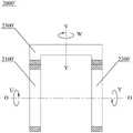
图1为根据本发明的一个示例性实施例的双侧反向输出装置的立体图;1 is a perspective view of a double-sided reverse output device according to an exemplary embodiment of the present invention;
图2为图1所示的双侧反向输出装置剖视图;2 is a cross-sectional view of the double-sided reverse output device shown in FIG. 1;
图3为根据本发明的一个示例性实施例的齿轮换向机构的示意图;3 is a schematic diagram of a gear reversing mechanism according to an exemplary embodiment of the present invention;
图4为根据本发明的另一个示例性实施例的齿轮换向机构的示意图;4 is a schematic diagram of a gear reversing mechanism according to another exemplary embodiment of the present invention;
图5a-5b为根据本发明的一个示例性实施例的带轮换向机构的示意图;5a-5b are schematic diagrams of a pulley reversing mechanism according to an exemplary embodiment of the present invention;
图6为图2中的齿轮换向机构的剖视图;6 is a cross-sectional view of the gear reversing mechanism in FIG. 2;
图7为图6中的齿轮换向机构的局部放大图;Fig. 7 is a partial enlarged view of the gear reversing mechanism in Fig. 6;
图8为根据本发明的一个示例性实施例的电机的剖视图;8 is a cross-sectional view of a motor according to an exemplary embodiment of the present invention;
图9为图8中的电机的局部放大图;以及FIG. 9 is a partial enlarged view of the motor in FIG. 8; and
图10为图1中的双侧反向输出装置的主视图。FIG. 10 is a front view of the double-sided reverse output device in FIG. 1 .
其中,上述附图包括以下附图标记:Wherein, the above-mentioned drawings include the following reference signs:
1000、电机;1100、转子;1101、第一转动输出端;1102、第二转动输出端;1110、第一适配孔;1120、主动轮安装孔;1130、转子芯;1140、永磁体;1141、第一磁钢;1142、第二磁钢;1200、定子;1210、定子芯;1211、定子齿极;1212、定子槽;1300、电机壳体;2000、2000’、2000”、2000”’、换向机构;2100、2100’、2100”、2100”’、主动轮;2101、第一端面;2102、第二端面;2110、第一凸柱;2120、凸轴;2121、环形凹槽;2200、2200’、2200”、2200”’、从动轮;2201、第三端面;2202、第四端面;2210、凸轴安装孔;2220、第二凸柱;2221、第二适配孔;2300、2300’、2300”、2300”’、传动组件;2400、第一轴承;2500、卡箍;2600、换向机构壳体;2610、安装通孔;2700、传动组件枢转轴;2710、第二轴承;3100、第一适配器;3110、第一连杆;3120、第一适配部;3200、第二适配器;3210、第二连杆;3220、第二适配部。1000, motor; 1100, rotor; 1101, first rotation output end; 1102, second rotation output end; 1110, first adapter hole; 1120, driving wheel mounting hole; 1130, rotor core; 1140, permanent magnet; 1141 , first magnet; 1142, second magnet; 1200, stator; 1210, stator core; 1211, stator tooth pole; 1212, stator slot; 1300, motor housing; 2000, 2000', 2000", 2000" ', reversing mechanism; 2100, 2100', 2100", 2100"', driving wheel; 2101, first end face; 2102, second end face; 2110, first convex column; 2120, convex shaft; 2121, annular groove ;2200, 2200', 2200", 2200"', driven wheel; 2201, the third end face; 2202, the fourth end face; 2210, the mounting hole of the convex shaft; 2220, the second convex column; 2221, the second matching hole; 2300, 2300', 2300", 2300"', transmission assembly; 2400, first bearing; 2500, clamp; 2600, reversing mechanism housing; 2610, mounting through hole; 2700, transmission assembly pivot shaft; 2710, No. Two bearings; 3100, the first adapter; 3110, the first link; 3120, the first adapter; 3200, the second adapter; 3210, the second link; 3220, the second adapter.
具体实施方式Detailed ways
在下文的描述中,提供了大量的细节以便能够彻底地理解本发明。然而,本领域技术人员可以了解,如下描述仅示例性地示出了本发明的优选实施例,本发明可以无需一个或多个这样的细节而得以实施。此外,为了避免与本发明发生混淆,对于本领域公知的一些技术特征未进行详细描述。In the following description, numerous details are provided in order to enable a thorough understanding of the present invention. It will be appreciated by those skilled in the art, however, that the following description is merely illustrative of preferred embodiments of the invention and that the invention may be practiced without one or more of these details. Furthermore, some technical features known in the art are not described in detail in order to avoid confusion with the present invention.
根据本发明的一个方面,提供了一种双侧反向输出装置。双侧反向输出装置包括电机1000和换向机构2000。如图1-2所示。换向机构2000可以设置在电机1000的内部也可以设置在电机100的外部。换向机构2000设置在电机1000的内部,可以使双侧反向输出装置整体结构更为紧凑,密封性好。换向机构2000设置在电机1000的外部,则可以使结构简单,加工成本低,易于实现。According to one aspect of the present invention, a double-sided reverse output device is provided. The double-sided reverse output device includes a
电机1000可以包括现有的或未来可能出现的任一种电机。电机1000可以包括转子1100。转子1100可以为电机1000的旋转部分,转子1100可以绕其中心轴线转动O-O。转子1100可以包括第一转动输出端1101和第二转动输出端1102。第一转动输出端1101和第二转动输出端1102可以沿转子1100的中心轴线O-O相对设置。第一转动输出端1101和第二转动输出端1102可以绕中心轴线O-O转动。第一转动输出端1101和第二转动输出端1102在转子1100上可以具有多种结构,该结构可以为在转子1100的端部延伸出的平键轴或花键轴,还可以为在转子1100的端部设置的连接孔等。
换向机构2000可以包括主动轮2100、从动轮2200和传动组件2300。主动轮2100可以与转子1100的第二转动输出端1102同轴固定。主动轮2100可以随转子1100转动。固定方式可以包括螺纹连接、焊接或其他任意连接方式。从动轮2200绕中心轴线O-O可转动。也就是说主动轮2100、从动轮2200以及转子1100可以同轴设置,且均可绕中心轴线O-O转动。传动组件2300可以连接主动轮2100和从动轮2200。传动组件2300可以用于使从动轮2200相对于主动轮2100反向转动。换向机构2000可以包括齿轮换向机构、带轮换向机构或任意一种转动机构。在一些实施例中,换向机构2000可以为减速机,减速机可以具有输入端和输出端。输入端和输出端可以在减速机内的传动元件的作用下实现输出端与输入端的反向旋转。当然,换向机构2000不局限于减速机,下文还将对换向机构2000的其他实施例进行详细的描述。The reversing
其中,第一转动输出端1101可以用于连接第一适配器3100。从动轮2200可以用于连接第二适配器3200。在一些实施例中,第一适配器3100和第二适配器3200可以包括脚踏组件、手柄组件或是任意通过转动可以达到康复训练和数字键身的装置。Wherein, the first
在如图2所示的实施例中,当电机1000工作时,转子1100转动。转子1100可以绕中心轴线O-O以转动方向U转动。同时,转子1100可以带动第一适配器3100以及主动轮2100也以转动方向U转动。传动组件2300连接在主动轮2100和从动轮2200之间,转子1100的动力可以通过主动轮2100和传动组件2300传递至从动轮2200,最终使从动轮2200以及与从动轮2200连接的第二适配器绕中心轴线O-O以转动方向V转动。其中,转动方向U和转动方向V方向相反。In the embodiment shown in FIG. 2, when the
由于转子1100、主动轮2100和第一适配器3100相对固定连接,所以转子1100、主动轮2100和第一适配器3100可以同步转动。由于从动轮2200和第二适配器3200相对固定连接,所以从动轮2200和第二适配器3200可以同步转动。为了方便对转速进行描述,仅以主动轮2100和从动轮2200的转动方向和转速进行描述。示例性地,由于第一适配器3100和第二适配器3200的用途不同,所以第一适配器3100和第二适配器3200的使用方式也可以不同。用户可以根据第一适配器3100和第二适配器3200的功能对换向机构2000进行合理地选择。在一些实施中,换向机构2000可以使主动轮2100和从动轮2200反向同步转动,也就是说换向机构2000仅改变主动轮2100和从动轮2200的转动方向,主动轮2100和从动轮2200具有相同的转速。在另一些实施例中,换向机构2000还可以使主动轮2100和从动轮2200反向异步转动,主动轮2100和从动轮2200可以具有不同的转速。在主动轮2100和从动轮2200具有不同的转速的实施例中,换向机构2000既可以充当减速器也可以充当加速器,本领域技术人员可以理解。Since the
可以理解的是,主动轮2100与从动轮2200的转速跟以其两个轮与传动组件2300的传动比有关。优选地,主动轮2100与传动组件2300的传动比等于从动轮2200与传动组件2300的传动比。这样,经过传动组件2300的传动,从动轮2200的转动方向可以与主动轮2100的转动方向相反,且从动轮2200与主动轮2100具有相同的转速。以第一适配器3100和第二适配器3200用于训练用户的双侧肢体为例,主动轮2100和从动轮2200转速相同可以起到对双侧肢体平均训练的效果。当然可以理解的是,有特殊需求的用户也可以通过改变以上所述的传动比满足用户的需求。It can be understood that the rotational speed of the
由此可知,具有本发明实施例所提供的双侧反向输出装置,可以在一个电机为动力源的情况下,向两个用于连接于第一适配器3100和第二适配器3200的输出端传输动力。其中,两个输出端具有同轴以及转动方向相反的特点。具有该设置的双侧反向输出装置应用于康复训练设备中,可以帮助患者对双侧肢体进行协同训练。进一步地,由于两个输出端带动的第一适配器3100和第二适配3200的转动方向相反,与患者正常的使用习惯不同,还可以对患者的运动机能起到刺激的作用,提高康复训练的效果。相比现有技术中,两个转向不同的输出端需要通过两个电机来说,可以减少电机数量的设置,提高产品的集成度,缩小产品尺寸。对于单出轴电机与多输出轴减速机进行连接来说,结构简单,连接方便,成本低廉。对于双出轴电机来说,可以实现双侧反向输出的效果。It can be seen that, with the double-sided reverse output device provided by the embodiment of the present invention, when one motor is the power source, the transmission can be transmitted to the two output ends connected to the
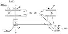
在如图2-4所述的实施例中,换向机构可以为齿轮换向机构。主动轮可以为主动齿轮。从动轮可以为从动齿轮,传动组件可以为中间齿轮。中间齿轮可以直接啮合在主动齿轮和从动齿轮之间。中间齿轮可以为单个齿轮,也可以为齿轮组。主动齿轮可以通过中间齿轮将动力传递至从动齿轮上。为了方便,下文将主动齿轮、从动齿轮和中间齿轮统称为齿轮。按照齿轮的形状分类,齿轮可以包括圆柱齿轮、锥齿轮或蜗杆等。按照齿型的分类,齿轮可以包括直齿齿轮、斜齿齿轮或人字齿齿轮等。当然,在中间齿轮为齿轮组的实施例中,也可以将多种齿轮进行组合实现主动齿轮与从动齿轮反向转动的效果。In the embodiments described in Figures 2-4, the reversing mechanism may be a gear reversing mechanism. The driving wheel may be a driving gear. The driven wheel can be a driven gear, and the transmission component can be an intermediate gear. The intermediate gear can be directly meshed between the driving gear and the driven gear. The intermediate gear can be a single gear or a gear set. The driving gear can transmit power to the driven gear through the intermediate gear. For convenience, the driving gear, the driven gear and the intermediate gear are collectively referred to as gears hereinafter. According to the shape of gears, gears can include cylindrical gears, bevel gears or worms. According to the classification of tooth type, gears can include spur gears, helical gears or herringbone gears. Of course, in the embodiment in which the intermediate gear is a gear set, multiple gears can also be combined to achieve the effect of reverse rotation of the driving gear and the driven gear.
示例性地,如图3所示,主动齿轮和从动齿轮可以沿着中心轴线O-O间隔开设置。在一些实施例中,主动齿轮和从动齿轮可以面对面的设置。中间齿轮的枢转轴线Y-Y可以是固定的且可以垂直于中心轴线O-O。主动齿轮、从动齿轮和中间齿轮可以均为外啮合齿轮。在一些实施例中,主动轮2100’和从动轮2200’可以为圆柱齿轮,传动组件2300’可以为冠齿轮。圆柱齿轮的齿可以分布在其周面上(图中阴影部分表示齿)。冠齿轮的齿可以分布在端面上。在使用时,作为主动轮2100’的主动齿轮和作为从动轮2200’的从动齿轮可以面对面的设置。作为传动组件2300’的冠齿轮则可以设置在主动齿轮和从动齿轮的中间靠外侧部分。其中,冠齿轮的枢转轴线Y-Y可以与中心轴线O-O垂直相交。主动齿轮可以沿转动方向U转动。通过啮合连接,主动齿轮可以驱动冠齿轮沿转动方向W转动。冠齿轮可以再次通过啮合驱动从动齿轮沿转动方向V转动。这样,就可以起到使主动轮2100’和从动轮2200’反向转动的效果。以冠齿轮作为传动组件2300’的优点在于体积小,结构紧凑,传递扭矩大。Illustratively, as shown in FIG. 3 , the driving gear and the driven gear may be spaced apart along the central axis O-O. In some embodiments, the driving gear and the driven gear may be arranged face to face. The pivot axis Y-Y of the intermediate gear may be fixed and may be perpendicular to the central axis O-O. The driving gear, the driven gear and the intermediate gear may all be externally meshing gears. In some embodiments, the driving wheel 2100' and the driven wheel 2200' may be spur gears, and the transmission assembly 2300' may be a crown gear. The teeth of the spur gear can be distributed on its circumference (the shaded part in the figure represents the teeth). The teeth of the crown gear can be distributed on the end face. In use, the driving gear as the driving wheel 2100' and the driven gear as the driven wheel 2200' may be arranged face to face. The crown gear serving as the transmission assembly 2300' can be arranged at the middle and outer part of the driving gear and the driven gear. Wherein, the pivot axis Y-Y of the crown gear may intersect the central axis O-O perpendicularly. The driving gear can rotate in the rotational direction U. Through the meshing connection, the driving gear can drive the crown gear to rotate in the rotational direction W. The crown gear can again drive the driven gear to rotate in the rotational direction V through meshing. In this way, the driving wheel 2100' and the driven wheel 2200' can be rotated in the opposite direction. The advantages of using the crown gear as the transmission assembly 2300' lie in its small size, compact structure and large transmission torque.
优选地,如图2所示,主动轮2100、从动轮2200和传动组件2300可以均为锥形齿轮。锥形齿轮也可以叫伞齿轮,可以用于相交轴之间的传动。其中,主动轮2100和从动轮2200的中心轴线O-O可以与传动组件2300的枢转轴线Y-Y相交。锥形齿轮被大量用于工业传动领域,其优点在于制造和安装较为简单。Preferably, as shown in FIG. 2 , the
示例性地,在齿轮传动机构中,主动齿轮和从动齿轮中的一个可以为外啮合齿轮且另一个可以为内啮合齿轮。外啮合齿轮可以设置在内啮合齿轮的径向内侧。传动组件2300可以为中间齿轮,中间齿轮可以为外啮合齿轮。中间齿轮的枢转轴线可以是固定的且平行于中心轴线。如图4所示,以换向机构2000”包括行星轮系为例,主动轮2100”可以为外啮合齿轮,从动轮2200”可以为内啮合齿轮,传动组件2300”可以为一个或多个作为行星轮的的外啮合齿轮,图4中的行星轮的数量为3个。当主动轮2100”沿转动方向U转动时,将可以带动作为传动组件2300”的行星轮沿转动方向W转动。其中,由于主动轮2100”和传动组件2300”为外啮合关系,所以转动方向U和转动方向W相反。行星轮的枢转轴线固定,那么此时的行星轮将可以驱动作为从动轮2200”的内啮合齿轮转动。从动轮2200”将可以沿转动方向V转动。由于从动轮2200”和传动组件2300”为内啮合关系,所以转动方向W和转动方向V相同。从而使得主动轮2100”与从动轮2200”可以反向转动。另外,通过改变行星轮与各个啮合齿轮的齿数比,以及控制行星轮的枢转轴线是否可绕中心轴线O-O转动,可以改变主动轮2100”和从动轮2200”的转速。Illustratively, in a gear transmission, one of the driving gear and the driven gear may be an external gear and the other may be a ring gear. The external gear may be arranged radially inward of the internal gear. The
示例性地,如图5a-5b所示,换向机构2000”’可以为带轮换向机构。主动轮2100”’可以为主动带轮。从动轮2200”’可以为从动带轮。传动组件2300”’可以包括中间带轮2310”’、第一传动带2320””和第二传动带2330”’。第一传动带2320”’可以连接主动轮2100”’和中间带轮2310”’。第二传动带2330”’可以连接中间带轮2310”’和从动轮2200”’。其中,第一传动带2320”’和第二传动带2330”’中的一个可以采用开口传动且另一个采用交叉传动。在如图5a-5b所示的实施例中,第一传动带2320”’为交叉传动,第二传动带2330”’为开口传动。当主动轮2100”’以转动方向U转动时,可以通过第一传动带2320”’将动力传递至中间带轮2310”’,由于第一传动带2320”’为交叉传动,所以中间带轮2310”’以转动方向W转动,其中,转动方向U和转动方向W反向。中间带轮2310”’可以再通过第二传动带2330”’将动力传递至从动轮2200”’,由于第二传动带2330”’为开口传动,所以从动轮2200”’可以与中间带轮2310”’同方向转动。从动轮2200”’的转动方向V与中间带轮2310”’的转动方向W相同。通过该实施例所述的传动结构,可以使得主动轮2100”’和从动轮2200”’都绕同一中心轴线转动,且转动方向相反。当然,可以理解的是,改变主动轮2100”’、中间带轮2310”’和从动轮2200”’的直径,可以改变主动轮2100”’和从动轮2200”’的转速,本领域技术人员熟知,不再赘述。Illustratively, as shown in Figures 5a-5b, the reversing
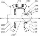
示例性地,如图2所示,主动轮2100和从动轮2200中的一个上可以设置有沿中心轴线O-O且朝向另一个延伸的凸轴2120,且另一个可枢转地套设在凸轴2120上。这样,通过设置凸轴2120,就可以使主动轮2100和从动轮2200枢转连接。在如图2中所示的实施例中,凸轴2120可以设置在主动轮2100上,这样,从动轮2200就可以套设在主动轮2100上。在使用时,从动轮2200可以在主动轮2100上的凸轴2120上转动。在现有技术中,通常是分别独立地设置主动轮2100的枢转轴和从动轮2200的枢转轴。这就导致两个枢转轴在加工过程中,容易产生误差,同轴度低。安装主动轮2100和从动轮2200之后,主动轮2100和从动轮2200的枢转轴线的同轴度也会较低,在换向机构2000转动过程中,容易产生振动、噪音以及不必要的磨损。不仅减少了产品的使用寿命,还影响了用户的使用体验。本发明实施例所提供的换向机构2000,可以提高主动轮2100和从动轮2200的同轴度,并且由于主动轮2100和从动轮2200通过凸轴2120连接,还可以提高主动轮2100和从动轮2200的结构强度,使主动轮2100和从动轮2200受凸轴2120的限制,减小了主动轮2100和从动轮2200在垂直于中心轴线O-O方向上的相对移动,提高了换向机构2000的机械性能和传动性能。Exemplarily, as shown in FIG. 2 , one of the
示例性地,如图6所示,主动轮2100可以包括O-O中心轴线相对设置的第一端面2101和第二端面2102。从动轮2200可以包括中心轴线O-O相对设置的第三端面2201和第四端面2202。第二端面2102可以与第三端面2201面对面设置。第一端面2101可以与转子1100的第二转动输出端固定1102。第二端面2102可以设置有沿中心轴线O-O延伸的凸轴2120。第三端面2201可以设置有沿中心轴线O-O延伸的凸轴安装孔2210。凸轴2120可枢转地与凸轴安装孔2210连接。在如图6所示的实施例中,仅示出了凸轴2120设置在具有锥齿轮的齿轮换向机构中,可以理解的是,在其他齿轮换向机构或带轮换向机构中,只要主动轮2100和从动轮2200同轴设置,也可以参考使用该结构。具有该结构的换向机构2000,可以提高主动轮2100和从轮动2200的同轴度,结构简单,易于实现。Exemplarily, as shown in FIG. 6 , the
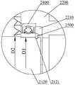
示例性地,凸轴安装孔2210内可以设置有第一轴承2400。第一轴承2400的外圈可以与凸轴安装孔2210的内周壁固定连接。凸轴2120的端部可以插接在第一轴承2400的内圈中且与内圈固定连接。第一轴承2400可以包括现有的或为来可能出现的任一种轴承,例如滚珠轴承、滚子轴承或滚针轴承等。设置有第一轴承2400的换向机构2000可以减少从动轮2200与凸轴2120之间的摩擦力,使得从动轮2200可以更加顺滑在凸轴2120上转动,还可以减少从动轮2200在转动过程中产生的噪音,提高用户的使用体验。Exemplarily, a
示例性地,如图7所示,凸轴2120可以为具有第一直径D1和第二直径D2的台阶轴。其中,第一直径D1可以小于第二直径D2。第一轴承2400可以过盈配合在具有第一直径D1的台阶轴上。在具有第一直径的台阶轴的外周壁上可以设置有环形凹槽2121。环形凹槽2121内可以设置有卡箍2500。第一轴承2400可以穿设在具有第一直径的台阶轴上。第一轴承2400可以夹设在第二直径的台阶轴的侧壁与卡箍2500之间。具有该设置的凸轴2120,可以使第一轴承2400牢固地安装在凸轴2120上,避免第一轴承2400在凸轴2120的轴向方向上移动,提高从动轮2200在凸轴2120上转动时的平稳度,减少从动轮2200在转动过程中产生的噪音。Exemplarily, as shown in FIG. 7 , the protruding
示例性地,如图2所示,转子1100的第二转动输出端1102处可以设置有沿中心轴线O-O延伸的主动轮安装孔1120。主动轮2100上可以设置有沿中心轴线O-O延伸第一凸柱2110。第一凸柱2110可以插接在主动轮安装孔1120内且与主动轮安装孔1120固定。在一些实施例中,第一凸柱2110可以通过螺纹、卡扣或焊接等方式与主动轮安装孔1120固定连接,从而使转子1100与主动轮2100可以同步转动。Exemplarily, as shown in FIG. 2 , the second
在如图2所示的实施例中,转子1100和主动轮2100可以通过螺纹连接。螺纹连接结构简单,易于实现。In the embodiment shown in FIG. 2 , the
在一个优选的实施例中,转子1100与主动轮2100之间可以设置有联轴器(未示出)。主动轮2100可以通过联轴器连接至转子1100上。设置联轴器可以方便转子1100与主动轮2100拆装,方便用户对产品进行维修和维护。In a preferred embodiment, a coupling (not shown) may be provided between the
进一步地,联轴器可以为免键轴衬。免键轴衬是一种靠摩擦联接的工具。免键轴衬可以将螺栓连接的紧固力通过锥面转换为对内径侧面的表面压力,同时不需要费时的轴和连轴部的键加工,组装时的磨合作业可以使轴和连轴部牢固连接。免键轴衬为本领域技术人员所熟知的,不再赘述。在如图2所示的实施例中,免键轴衬的外圈可以与转子1100和主动轮2100中的一个固定连接。免键轴衬的内圈可以与转子1100和主动轮2100中的另一个固定连接。其中,固定连接的连接力可以是免键轴衬分别与转子1100和主动轮2100之间的摩擦力。通过使用免键轴衬连接转子1100和主动轮2100,可以减少安装工序,提高安装质量和安装效率。Further, the coupling may be a keyless bushing. The keyless bushing is a tool that is connected by friction. The keyless bushing can convert the tightening force of the bolted connection into the surface pressure on the inner diameter side through the tapered surface, and at the same time, it does not require time-consuming key processing of the shaft and the connecting shaft, and the grinding operation during assembly can make the shaft and connecting shaft. Connect securely. Keyless bushings are well known to those skilled in the art and will not be repeated here. In the embodiment shown in FIG. 2 , the outer ring of the keyless bushing may be fixedly connected with one of the
示例性地,如图2所示,转子1100的第一转动输出端1101处可以设置有沿转子1100的中心轴线O-O延伸的第一适配孔1110。第一适配孔1110可以用于与第一适配器3100固定连接。第一适配器3100可以插接在第一适配孔1110内。设置第一适配孔1110可以方便第一适配器3100与转子1100的连接,还可以提高第一适配器3100与转子1100的同轴度。Exemplarily, as shown in FIG. 2 , the first
示例性地,第一适配孔1110可以与主动轮安装孔1120连通且形成沿中心轴线O-O贯通的内径均匀的孔。也就是说,转子1100可以为具有通轴,这样,不仅可以方便第一适配器3100和主动轮2100安装,还可以减少转子1100的材料,从而减轻转子110的质量,减少转动惯量。Exemplarily, the first fitting hole 1110 may communicate with the driving wheel mounting hole 1120 and form a hole with a uniform inner diameter passing through along the central axis O-O. That is, the
示例性地,换向机构2000可以包括换向机构壳体2600。在换向机构壳体2600上可以设置有沿中心轴线O-O延伸的从动轮安装通孔2610。从动轮2200上可以设置有沿中心轴线O-O延伸的第二凸柱2220。第二凸柱2220可枢转地插接在从动轮安装通孔2610内。具有该设置的换向机构2000,从动轮2200可以与换向机构壳体2600枢转连接,提高从动轮2200在转动过程中的稳定性,避免单纯仅靠主动轮2100上的凸轴2120支撑从动轮所带来的受力不均的情况。Illustratively, the reversing
进一步地,第二凸柱2220上可以设置有沿中心轴线O-O延伸的第二适配孔2221。第二适配孔2221可以用于与第二适配器3200固定连接。设置第二适配孔2221可以方便第二适配器3200与从动轮2200的连接,还可以提高第二适配器3200与从动轮2200的同轴度。Further, a second
示例性地,转子1100的第一转动输出端1101可以设置有用于与第一适配器3100连接的第一适配孔1110。从动轮2200上可以设置有用于与第二适配器3200连接的第二适配孔2221。第一适配孔1110可以与第二适配孔2221具有相同的构造。在一些实施例中,第一适配孔1110和第二适配孔2221可以具有相同的内径,这样,在第一适配器3100和第二适配器3200具有相同的结构的基础上,第一适配器3100和第二适配器3200可以替换使用,提高第一适配器3100和第二适配器3200的互换性。Exemplarily, the first
示例性地,电机1000还可以包括电机壳体1300和定子1200。定子1200可以通过热压固定在电机壳体1300内。转子1100可以穿设在定子1200内。在一些实施例中,可以在定子1200与电机壳体1300安装前,先对电机壳体1300进行加热,使电机壳体1300受热膨胀。这样,电机壳体1300的内径与定子1200的外径之间就可能产生便于安装的缝隙。将定子1200放入至电机壳体1300内后,待电机壳体1300冷却,电机壳体1300与定子1200将可以紧密连接在一起。这样,可以减少在电机壳体1300与定子1200之间设置连接件,而且,还可以提高电机壳体1300与电子1200之间的对中性,提高电机1000的安装精度,从而有利于提高电机1000的性能。Exemplarily, the
示例性地,在电机1000包括电机壳体1300,换向机构2000包括换向机构壳体2600的实施例中,转子1100可以设置在电机壳体1300内,主动轮2100、从动轮2200和传动组件2300可以设置在换向机构壳体2600内。电机壳体1300和换向机构壳体2600可以为一体件。一体件可以包括电机壳体1300与换向机构壳体2600作为一体件生产加工,还可以包括在电机1000与换向机构2000连接之后形成不可拆卸的一体结构。其中,电机壳体1300和换向机构壳体2600可以通过铸造形成一体件,还可以通过焊接等方式形成一体件。电机壳体1300和换向机构壳体2600为一体件可以提高双侧反向输出装置的一体结构,提高使用过程中的可靠性。Exemplarily, in the embodiment in which the
示例性地,换向机构壳体2600内可以设置有传动组件枢转轴2700。传动组件2300可枢转地套设在传动组件枢转轴2700上。在一些实施例中,传动组件枢转轴2700可以为设置在换向机构壳体2600内部的凸轴。传动组件枢转轴2700可以与换向机构壳体2600铸造连接。Exemplarily, a transmission
示例性地,传动组件枢转轴2700上可以套设有第二轴承2710。第二轴承2710的内圈可以与传动组件枢转轴2700的外周壁固定连接。传动组件2300可以与第二轴承2710的外圈固定连接。设置第二轴承2710可以减小传动组件枢转轴2700与传动组件2300之间的摩擦力,使传动组件2300转动更为顺滑,提高换向机构2000的工作效率,减少换向机构2000工作时产生的噪音。Exemplarily, a
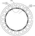
示例性地,如图8所示,电机1000还可以包括定子1200。定子1200与转子1100可以同轴设置。定子1200可以包括定子芯1210及设置于定子芯1210上的定子绕组。在一个实施例中,定子绕组可以包括绕在定子芯1210上面的铜线。转子1100可以包括转子芯1130及依次排列于转子芯1130上的多个永磁体1140。多个永磁体1140可以依次排列于转子芯1130的外圆周上。定子1200与转子1100可以同轴设置且在定子1200与转子1100之间可以形成气隙。电机1000通电后,可以在定子绕组周围形成一个绕驱动电机几何轴线旋转的磁场。该几何轴线可以是定子1200和转子1100的轴线。该磁场可以驱动转子1100上的永磁体1140转动,从而带动转子1100转动。电机1000的性能和永磁体1140的数量、永磁体1140的磁通强度、电机输入电压大小等因素有关。本发明实施例中的电机1000,永磁体1140可以为海尔贝克阵列型永磁体。海尔贝克阵列可以通过将不同充磁方向的永磁体按照一定规律排列,就可以在磁体一侧汇聚磁力线,而在另一侧削弱磁力线,从而获得比较理想的单边磁场。通过该种规律排列的永磁体,可以增强单位方向上的场强,从而达到用最少量的永磁体1140产生最强的磁场。Exemplarily, as shown in FIG. 8 , the
相较于现有电机来说,具有海尔贝克阵列型永磁体的电机,可以在产生相同磁场的条件下,使用更少的永磁体,从而使电机内更多的空间用于增大转子半径。转子1100的半径越大,在相同的电磁力下所产生的扭矩也就越大。由于电机的输出扭矩增大,在组成本发明中的双侧反向输出装置时,就可以在双侧反向输出装置中无需设置中间装置(例如减速机等),从而使双侧反向输出装置的惯量减小,响应速度可以提高。而且,双侧反向输出装置在传递动力的过程中,还可以减少动力的损耗。进一步地,由于无需设置中间装置,还可以减小双侧反向输出装置的尺寸,使双侧反向输出装置的集成度更高。Compared with existing motors, motors with Halbeck array permanent magnets can use fewer permanent magnets under the condition of generating the same magnetic field, so that more space in the motor can be used to increase the radius of the rotor. The larger the radius of the
示例性地,定子绕组可以采用分数槽集中绕组。其中,在定子芯1210的内圆周上设有多个沿其周向间隔开布置的定子齿极1211。相邻两个定子齿极1211之间限定出定子槽1212。定子齿极1211上可以缠绕有绕组线圈。即定子齿极1211和定子槽1212依次设置。定子芯1210还可以包括桶状的壳体,定子齿极1211的根部与壳体连接,定子齿极1211的端部朝向定子的轴线延伸。绕组线圈可以缠绕在定子齿极1211上。在集中绕组中,每个绕组线圈在相应的定子齿极1211上缠绕完后,可以进入相邻的下一个定子齿极1211上进行缠绕,而不必跨过相邻的定子齿极去进行缠绕。这样,绕组线圈无重叠,相互之间绝缘好。另外,线圈端部的长度可以更短,这样,就可以更好地控制电机在其轴向上的长度,进一步减小电机的尺寸,有利于降低产品成本,而且还可以很好地控制电机的发热。Illustratively, the stator windings may adopt fractional slot concentrated windings. A plurality of
示例性地,定子芯1210上可以设置有21个定子槽1212,转子芯1130上可以设置22个磁极,每个磁极可以包括一对海尔贝克阵列型永磁体。这样,定子槽1212的数量与磁极之间产生的最小公倍数就会很大。最小公倍数越大,转子1100每转动一圈所被划分的份数就越多,这样,力矩波动较小,电机转动时就会相对较平稳,而且还可以减小电机的齿槽力矩。Exemplarily, the
示例性地,永磁体1140可以沿转子1100的轴向长度比定子芯1210的轴向长度大10%。这样,可以提高永磁体1140所产生的磁场,从而提高电机的转矩。Illustratively, the
示例性地,定子槽1212还可以设置为斜槽,也就是说定子槽1212与定子的轴线呈有一定的夹角,不平行。其中,定子槽1212的倾斜量可以为n个定子槽距,其中n小于1。定子槽1212具有相互连通的第一端和第二端,若定子槽1212不倾斜,那么由第一端开始,沿定子的轴线延伸即为该定子槽1212的第二端。若倾斜量n为1,那么由该定子的第一端开始,沿定子的轴线延伸,将达到相邻定子槽的第二端,这样以此类推。Exemplarily, the
具有该设置的电机,可以减少转子1100在转动时产生的振动和噪声,还可以减少转子1100在转动过程中产生的波动。The motor with this arrangement can reduce the vibration and noise generated by the
示例性地,n的取值范围为0.3~0.6。优选地,n可以为0.583。其中0.5为定子槽倾斜的槽距,0.083是考虑到制造工艺误差选取的安全余量。根据物理实验所得,由于定子绕组采用集中绕组的形式,所以,如果n为0.5,就可以把输出的力矩波动降低10倍以上,但同时输出的力矩只会降低8%~10%,该力矩波动已经可以满足正常使用的需要,但是如倾斜1个槽距,虽然力矩波动会进一步降低,但力矩也将要损失15%以上。综上,优选地,n可以选取0.583。Exemplarily, the value of n ranges from 0.3 to 0.6. Preferably, n may be 0.583. Among them, 0.5 is the slot pitch of the stator slot inclination, and 0.083 is the safety margin selected in consideration of the manufacturing process error. According to the results of physical experiments, since the stator winding adopts the form of concentrated winding, if n is 0.5, the output torque fluctuation can be reduced by more than 10 times, but the output torque will only be reduced by 8% to 10%. It can already meet the needs of normal use, but if the slot pitch is inclined by one, although the torque fluctuation will be further reduced, the torque will also lose more than 15%. To sum up, preferably, n can be selected as 0.583.
示例性地,每个永磁体1140可以包括磁极方向相互垂直的第一磁钢1141和第二磁钢1142。在相邻排列的两个永磁体1140中,第一磁钢1141的磁极方向相反,第二磁钢1142的磁极方向相反,如图9所示。通过该种规律排列的永磁体,可以增强单位方向上的场强,从而达到用最少量的永磁体产生最强的磁场。在一些实施例中,第一磁钢和第二磁钢的宽度可以为6.5mm,高度可以为3mm,其中宽度是指沿转子周向方向上的尺寸,高度是指沿转子径向方向上的尺寸。Exemplarily, each
示例性地,第一磁钢1141和第二磁钢1142可以均为稀土磁钢。由于稀土磁钢具有高剩磁密度、高矫顽力和高磁能积的特点,可以容许所制成的电机具有较大的气隙长度和气隙密度,因而在永磁体安放和磁路结构设计上有很大灵活性,可以根据使用场合,制成与传统电机不同的结构形状和尺寸。这既可以进一步减少电机的质量和转动惯量,提高电机的反应灵敏度;又可以减少驱动电机转矩的脉动,增加运行的平稳性;还可以简化电机的结构和工艺。Exemplarily, the first
示例性地,电机还可以包括编码器。码器可以包括:磁码盘或光码盘以及电路板。电路板上可以集成有采集芯片和信号处理电路。采集芯片可以用于采集磁码盘或光码盘的变化信息。信号处理电路可以用于对变化信息进行处理,输出位置信息。Illustratively, the motor may also include an encoder. The encoder may include: a magnetic or optical encoder and a circuit board. A collection chip and a signal processing circuit may be integrated on the circuit board. The acquisition chip can be used to acquire the change information of the magnetic code disk or the optical code disk. The signal processing circuit can be used to process the change information and output the position information.
以磁码盘为例,磁码盘可以为依次排列的多个磁极形成的环形磁栅。电路板上可以集成有霍尔元件采集芯片和信号处理电路。霍尔元件采集芯片可以用于采集磁码盘的磁极变化信息,信号处理电路可以用于对磁极变化信息进行处理,输出位置信息。Taking a magnetic code disc as an example, the magnetic code disc may be a ring-shaped magnetic grid formed by a plurality of magnetic poles arranged in sequence. A Hall element acquisition chip and a signal processing circuit can be integrated on the circuit board. The Hall element acquisition chip can be used to collect the magnetic pole change information of the magnetic code disc, and the signal processing circuit can be used to process the magnetic pole change information and output the position information.
编码器的转动轴线可以和转子的轴线同轴。当转子1100转动时,可以带动编码器转动。霍尔元件采集芯片可以根据采集磁码盘的磁极变化信息对转子的转动角度精确测量。The axis of rotation of the encoder may be coaxial with the axis of the rotor. When the
具有光码盘的编码器和具有磁码盘的编码器工作原理大体相同,区别在于光码盘上具有可供光线透过的光栅,采集芯片可以为光敏元件采集芯片。光敏元件采集芯片可通过光栅接收到光线。信号处理电路可以用于对光线变化信息进行处理,输出位置信息。The working principle of an encoder with an optical code disc is basically the same as that of an encoder with a magnetic code disc. The difference is that the optical code disc has a grating for light to pass through, and the collection chip can be a photosensitive element collection chip. The photosensitive element collection chip can receive light through the grating. The signal processing circuit can be used to process the light change information and output the position information.
编码器检测电机的转动参数是本领域技术人员所熟知的,不再进行赘述。It is well known to those skilled in the art that the encoder detects the rotational parameters of the motor, and will not be repeated here.
优选地,编码器可以为大于或等于14位的绝对值编码器。大于或等于14位的绝对值编码器可以提高编码器对转子1100转动角度的精度。Preferably, the encoder may be an absolute value encoder greater than or equal to 14 bits. The absolute value encoder with greater than or equal to 14 bits can improve the accuracy of the encoder for the rotation angle of the
根据本发明的另一个方面,提供一种康复训练和数字健身设备。康复训练和数字健身设备可以包括双侧反向输出装置、第一适配器3100和第二适配器3200。第一适配器3100可以与转子1100的第一转动输出端1101固定。第二适配器3200可以与从动轮2200固定。其中,第一适配器3100和第二适配器3200可以包括脚踏组件或手柄组件,用户可以根据训练内容选择合适的第一适配器3100和第二适配器3200。According to another aspect of the present invention, a rehabilitation training and digital fitness equipment is provided. Rehabilitation and digital fitness equipment may include a double-sided reverse output device, a
示例性地,如图10所示,第一适配器3100可以包括第一连杆3110和第一适配部3120。第一连杆3110的一端可以与第一转动输出端1101固定。第一适配部3120可枢转地连接在第一连杆3110的另一端,且第一连杆3110与中心轴线O-O垂直。第二适配器3200可以包括第二连杆3210和第二适配部3220。第二连杆3210的一端可以与从动轮2200固定。第二适配部3220可枢转地连接在第二连杆3210的另一端,且第二连杆3210与中心轴线O-O垂直。以第一适配部3120和第二适配部3220均为脚踏为例。用户可以将双脚放置在脚踏上,利用电机1000的转动,驱动用户的下肢产生运动,达到训练的效果。当然,可以理解的是,在电机为伺服电机的实施例中,用户还可以对伺服电机的输出扭矩进行设置,当用户蹬踏脚踏时,电机可以产生与用户下肢运动方向相反的阻力,从而提高康复训练或是达到健身的效果。Exemplarily, as shown in FIG. 10 , the
示例性地,第一连杆3110和第二连杆3210在初始位置可以由中心轴线O-O朝向相同方向延伸。如图10所示,图中的双侧反向输出装置处于初始位置,第一连杆3110和第二连杆3210的延伸方向都向下。由于第一适配器3100和第二适配器3200的转动方向相反,在第一适配器3100和第二适配器3200转动速度相同的情况下,第一适配器3100或第二适配器3200每转动半圈,将可以位于处于朝向相同方向的位置。以图10作为初始位置,第一适配器3100和第二适配器3200转动半圈之后将可以共同处于朝向上方的位置。这样可以最大程度地使第一适配器3100和第二适配器3200的运动轨迹区别于用户的使用习惯,有效刺激用户的运动机能,提高康复训练或是达到健身的效果。当然,可以理解的是,根据训练内容的不同,第一适配器3100和第二适配器3200的初始位置还可以具有多种情况,不再赘述。Exemplarily, the
在本发明的描述中,需要理解的是,方位词如“前”、“后”、“上”、“下”、“左”、“右”、“横向”、“竖向”、“垂直”、“水平”和“顶”、“底”等所指示的方位或位置关系通常是基于附图所示的方位或位置关系,仅是为了便于描述本发明和简化描述,在未作相反说明的情况下,这些方位词并不指示和暗示所指的装置或元件必须具有特定的方位或者以特定的方位构造和操作,因此不能理解为对本发明保护范围的限制;方位词“内”、“外”是指相对于各部件本身的轮廓的内外。In the description of the present invention, it should be understood that orientation words such as "front", "rear", "upper", "lower", "left", "right", "horizontal", "vertical", "vertical" "," "horizontal" and "top", "bottom" and so on indicate the orientation or positional relationship is usually based on the orientation or positional relationship shown in the accompanying drawings, only for the convenience of describing the present invention and simplifying the description, in the absence of the opposite description Under the circumstance, these orientation words do not indicate and imply that the referred device or element must have a specific orientation or be constructed and operated in a specific orientation, so it cannot be construed as a limitation on the protection scope of the present invention; the orientation words “in”, “in” Outside" means inside and outside relative to the contours of the components themselves.
为了便于描述,在这里可以使用区域相对术语,如“在……之上”、“在……上方”、“在……上表面”、“上面的”等,用来描述图中所示的一个或多个部件或特征与其他部件或特征的区域位置关系。应当理解的是,区域相对术语不但包含部件在图中所描述的方位,还包括使用或操作中的不同方位。例如,如果附图中的部件被整体倒置,则部件“在其他部件或特征上方”或“在其他部件或特征之上”的将包括部件“在其他部件或构造下方”或“在其他部件或构造之下”的情况。因而,示例性术语“在……上方”可以包括“在……上方”和“在……下方”两种方位。此外,这些部件或特征也可以其他不同角度来定位(例如旋转90度或其他角度),本文意在包含所有这些情况。For ease of description, regionally relative terms, such as "on", "over", "on top of", "above", etc., may be used herein to describe what is shown in the figures. The regional positional relationship of one or more components or features to other components or features. It is to be understood that regionally relative terms encompass not only the orientation of components in the depicted figures, but also different orientations in use or operation. For example, if a component in the figures is turned upside down in its entirety, reference to the component "above" or "above" other components or features would include the components "below" or "above the other components or features" under the structure". Thus, the exemplary term "above" can encompass both an orientation of "above" and "below." In addition, these components or features may also be oriented at other different angles (eg, rotated 90 degrees or at other angles), all of which are intended to be encompassed herein.
需要注意的是,这里所使用的术语仅是为了描述具体实施方式,而非意图限制根据本申请的示例性实施方式。如在这里所使用的,除非上下文另外明确指出,否则单数形式也意图包括复数形式,此外,还应当理解的是,当在本说明书中使用术语“包含”和/或“包括”时,其指明存在特征、步骤、操作、部件、组件和/或它们的组合。It should be noted that the terminology used herein is for the purpose of describing specific embodiments only, and is not intended to limit the exemplary embodiments according to the present application. As used herein, unless the context clearly dictates otherwise, the singular is intended to include the plural as well, furthermore, it is to be understood that when the terms "comprising" and/or "including" are used in this specification, it indicates that There are features, steps, operations, parts, components and/or combinations thereof.
需要说明的是,本申请的说明书和权利要求书及上述附图中的术语“第一”、“第二”等是用于区别类似的对象,而不必用于描述特定的顺序或先后次序。应该理解这样使用的数据在适当情况下可以互换,以便这里描述的本申请的实施方式能够以除了在这里图示或描述的那些以外的顺序实施。It should be noted that the terms "first", "second", etc. in the description and claims of the present application and the above drawings are used to distinguish similar objects, and are not necessarily used to describe a specific sequence or sequence. It is to be understood that data so used may be interchanged under appropriate circumstances so that the embodiments of the application described herein can be practiced in sequences other than those illustrated or described herein.
本发明已经通过上述实施例进行了说明,但应当理解的是,上述实施例只是用于举例和说明的目的,而非意在将本发明限制于所描述的实施例范围内。此外本领域技术人员可以理解的是,本发明并不局限于上述实施例,根据本发明的教导还可以做出更多种的变型和修改,这些变型和修改均落在本发明所要求保护的范围以内。本发明的保护范围由附属的权利要求书及其等效范围所界定。The present invention has been described by the above-mentioned embodiments, but it should be understood that the above-mentioned embodiments are only for the purpose of illustration and description, and are not intended to limit the present invention to the scope of the described embodiments. In addition, those skilled in the art can understand that the present invention is not limited to the above-mentioned embodiments, and more variations and modifications can also be made according to the teachings of the present invention, and these variations and modifications all fall within the protection claimed in the present invention. within the range. The protection scope of the present invention is defined by the appended claims and their equivalents.
Claims (10)
Translated fromChinesePriority Applications (1)
| Application Number | Priority Date | Filing Date | Title |
|---|---|---|---|
| CN202210476019.8ACN114709975A (en) | 2022-04-29 | 2022-04-29 | Bilateral reverse output mechanism and rehabilitation training and digital fitness equipment with the same |
Applications Claiming Priority (1)
| Application Number | Priority Date | Filing Date | Title |
|---|---|---|---|
| CN202210476019.8ACN114709975A (en) | 2022-04-29 | 2022-04-29 | Bilateral reverse output mechanism and rehabilitation training and digital fitness equipment with the same |
Publications (1)
| Publication Number | Publication Date |
|---|---|
| CN114709975Atrue CN114709975A (en) | 2022-07-05 |
Family
ID=82176948
Family Applications (1)
| Application Number | Title | Priority Date | Filing Date |
|---|---|---|---|
| CN202210476019.8AWithdrawnCN114709975A (en) | 2022-04-29 | 2022-04-29 | Bilateral reverse output mechanism and rehabilitation training and digital fitness equipment with the same |
Country Status (1)
| Country | Link |
|---|---|
| CN (1) | CN114709975A (en) |
Cited By (1)
| Publication number | Priority date | Publication date | Assignee | Title |
|---|---|---|---|---|
| KR102648573B1 (en)* | 2023-04-06 | 2024-03-19 | 주식회사 휴젝트 | Energy harvesting apparatus using foothold |
- 2022
- 2022-04-29CNCN202210476019.8Apatent/CN114709975A/ennot_activeWithdrawn
Cited By (2)
| Publication number | Priority date | Publication date | Assignee | Title |
|---|---|---|---|---|
| KR102648573B1 (en)* | 2023-04-06 | 2024-03-19 | 주식회사 휴젝트 | Energy harvesting apparatus using foothold |
| WO2024210486A1 (en)* | 2023-04-06 | 2024-10-10 | 주식회사 휴젝트 | Energy harvesting device using pedals |
Similar Documents
| Publication | Publication Date | Title |
|---|---|---|
| US10250107B2 (en) | Magnetic-controlled generator with built-in controller | |
| CN100420125C (en) | Axial flux motor assembly | |
| TWI253800B (en) | Direct-current brushless motor combined with planetary gear train | |
| US20170326712A1 (en) | Driving Device And Power Tool Comprising Same | |
| CN220122721U (en) | Motor | |
| CN114709975A (en) | Bilateral reverse output mechanism and rehabilitation training and digital fitness equipment with the same | |
| CN202772781U (en) | Built-in generator and permanent magnet eddy current braking device | |
| CN218979608U (en) | Lower limb rehabilitation training device | |
| CN217769750U (en) | Bilateral reverse output device and rehabilitation training and digital fitness equipment with same | |
| CN114083526B (en) | Rotary motion modules and robots | |
| WO2023206509A1 (en) | Two-sided reverse output mechanism, and rehabilitation training and digital fitness apparatus having same | |
| CN105406687A (en) | Permanent magnet adjustable-speed motor | |
| CN208369436U (en) | A kind of moving-coil type unipolarity permanent magnet rotational alignment motor | |
| TWI675530B (en) | Electric machine with adjustable speed magnetic gear and motor, generator, and electric vehicle with the same | |
| CN204013053U (en) | Ball spline spindle motor | |
| CA1181484A (en) | Power absorbing device for low-temperature refrigerating machine | |
| CN216086377U (en) | Motor direct-drive concentric triaxial mechanism | |
| CN202503413U (en) | Brushless DC Motor | |
| CN207573177U (en) | Integrated variable speed electric motors, particularly | |
| CN112165231A (en) | Complementary axial air gap flux permanent magnet switched reluctance motor | |
| CN220711254U (en) | Flywheel power generation system and exercise bicycle | |
| EP3517778A1 (en) | Power producing apparatus | |
| CN219643671U (en) | Double-output-shaft bidirectional stepping motor | |
| CN218633658U (en) | Novel flywheel type outer rotor permanent magnet synchronous generator | |
| CN220257047U (en) | Intelligent tension simulator |
Legal Events
| Date | Code | Title | Description |
|---|---|---|---|
| PB01 | Publication | ||
| PB01 | Publication | ||
| SE01 | Entry into force of request for substantive examination | ||
| SE01 | Entry into force of request for substantive examination | ||
| WW01 | Invention patent application withdrawn after publication | ||
| WW01 | Invention patent application withdrawn after publication | Application publication date:20220705 |