CN114709915A - Power supply guarantee system - Google Patents
Power supply guarantee systemDownload PDFInfo
- Publication number
- CN114709915A CN114709915ACN202210308489.3ACN202210308489ACN114709915ACN 114709915 ACN114709915 ACN 114709915ACN 202210308489 ACN202210308489 ACN 202210308489ACN 114709915 ACN114709915 ACN 114709915A
- Authority
- CN
- China
- Prior art keywords
- power supply
- voltage
- link
- voltage converter
- powered
- Prior art date
- Legal status (The legal status is an assumption and is not a legal conclusion. Google has not performed a legal analysis and makes no representation as to the accuracy of the status listed.)
- Pending
Links
Images


Classifications
- H—ELECTRICITY
- H02—GENERATION; CONVERSION OR DISTRIBUTION OF ELECTRIC POWER
- H02J—CIRCUIT ARRANGEMENTS OR SYSTEMS FOR SUPPLYING OR DISTRIBUTING ELECTRIC POWER; SYSTEMS FOR STORING ELECTRIC ENERGY
- H02J9/00—Circuit arrangements for emergency or stand-by power supply, e.g. for emergency lighting
- H02J9/04—Circuit arrangements for emergency or stand-by power supply, e.g. for emergency lighting in which the distribution system is disconnected from the normal source and connected to a standby source
- H02J9/06—Circuit arrangements for emergency or stand-by power supply, e.g. for emergency lighting in which the distribution system is disconnected from the normal source and connected to a standby source with automatic change-over, e.g. UPS systems
- H02J9/061—Circuit arrangements for emergency or stand-by power supply, e.g. for emergency lighting in which the distribution system is disconnected from the normal source and connected to a standby source with automatic change-over, e.g. UPS systems for DC powered loads
- H—ELECTRICITY
- H02—GENERATION; CONVERSION OR DISTRIBUTION OF ELECTRIC POWER
- H02M—APPARATUS FOR CONVERSION BETWEEN AC AND AC, BETWEEN AC AND DC, OR BETWEEN DC AND DC, AND FOR USE WITH MAINS OR SIMILAR POWER SUPPLY SYSTEMS; CONVERSION OF DC OR AC INPUT POWER INTO SURGE OUTPUT POWER; CONTROL OR REGULATION THEREOF
- H02M3/00—Conversion of DC power input into DC power output
- H02M3/02—Conversion of DC power input into DC power output without intermediate conversion into AC
- H02M3/04—Conversion of DC power input into DC power output without intermediate conversion into AC by static converters
Landscapes
- Engineering & Computer Science (AREA)
- Power Engineering (AREA)
- Business, Economics & Management (AREA)
- Emergency Management (AREA)
- Control Of Indicators Other Than Cathode Ray Tubes (AREA)
Abstract
Description
Translated fromChinese技术领域technical field
本发明涉及系统供电技术领域。更具体地,涉及一种供电保障系统。The invention relates to the technical field of system power supply. More specifically, it relates to a power supply guarantee system.
背景技术Background technique
目前,为了提升系统供电的稳定性和可靠性,通常会选取环路备份供电或者主从备份供电的方式。然而,环路备份供电是仅可实现对供电链路(链路端)的备份,而主从备份供电虽然可以实现同时对供电链路和电源(源端)备份,但是,发明人发现,主从备份供电的方式会导致系统的链路较长、连接器(对接端子)数量较多,用于走线空间受限的系统存在困难。At present, in order to improve the stability and reliability of system power supply, loop backup power supply or master-slave backup power supply is usually selected. However, the loop backup power supply can only realize the backup of the power supply link (link end), and although the master-slave backup power supply can realize the backup of the power supply link and the power supply (source end) at the same time, the inventor found that the main The method of supplying power from the backup will lead to a long system link and a large number of connectors (butt terminals), which is difficult to use in a system with limited wiring space.
发明内容SUMMARY OF THE INVENTION
本发明的目的在于提供一种供电保障系统,以解决现有技术存在的问题中的至少一个。The purpose of the present invention is to provide a power supply guarantee system to solve at least one of the problems existing in the prior art.
为达到上述目的,本发明采用下述技术方案:To achieve the above object, the present invention adopts the following technical solutions:
本发明提供了一种供电保障系统,包括The present invention provides a power supply guarantee system, comprising:
电源装置和N个待供电装置,N≥2,所述电源装置包括第一电源、第二电源、第一供电链路和第二供电链路,所述第一电源位于第一供电链路的源端,所述第二供电链路位于第二供电链路的源端,各待供电装置分别接入所述第一供电链路和所述第二供电链路,A power supply device and N devices to be powered, N≥2, the power supply device includes a first power supply, a second power supply, a first power supply link, and a second power supply link, and the first power supply is located at the end of the first power supply link. a source end, the second power supply link is located at the source end of the second power supply link, and each device to be powered is connected to the first power supply link and the second power supply link, respectively,
其中,第n个待供电装置接入所述第一供电链路的接入位置相比于第n-1个待供电装置接入所述第一供电链路的接入位置,远离所述第一供电链路的源端;第n个待供电装置接入所述第二供电链路的接入位置相比于第n-1个待供电装置接入所述第二供电链路的接入位置,靠近所述第二供电链路的源端;n=2,…,N。Wherein, the access position where the nth device to be powered is connected to the first power supply link is far away from the access position where the n-1th device to be powered is connected to the first power supply link. A source end of a power supply link; the access position of the nth device to be powered on the second power supply link is compared to the access position of the n-1th device to be powered on the second power supply link position, close to the source end of the second power supply chain; n=2,...,N.
可选地,第n-1个待供电装置与第n个待供电装置之间的第一供电链路和第二供电链路共用一个连接器。Optionally, the first power supply link and the second power supply link between the n-1th device to be powered and the nth device to be powered share one connector.
可选地,所述第一电源用于向所述第一供电链路输出第一电压信号,所述第二电源用于向所述第二供电链路输出第二电压信号。Optionally, the first power supply is configured to output a first voltage signal to the first power supply link, and the second power supply is configured to output a second voltage signal to the second power supply link.
可选地,所述待供电装置包括电源模块和功能组件,所述电源模块包括电压转换器和电压接收器;Optionally, the device to be powered includes a power module and functional components, the power module includes a voltage converter and a voltage receiver;
所述电压转换器的输入端分别接入所述第一供电链路和所述第二供电链路,所述电压转换器的输出端连接所述电压接收器的输入端,所述电压接收器的输出端连接所述功能组件的供电输入端。The input terminals of the voltage converter are respectively connected to the first power supply link and the second power supply link, and the output terminal of the voltage converter is connected to the input terminal of the voltage receiver, and the voltage receiver The output terminal is connected to the power supply input terminal of the functional component.
可选地,所述电压转换器包括第一电压转换器和第二电压转换器,所述电源模块还包括第一反向二极管和第二反向二极管;Optionally, the voltage converter includes a first voltage converter and a second voltage converter, and the power module further includes a first reverse diode and a second reverse diode;
所述第一电压转换器的输入端接入所述第一供电链路,所述第二电压转换器的输入端接入所述第二供电链路;The input end of the first voltage converter is connected to the first power supply chain, and the input end of the second voltage converter is connected to the second power supply chain;
所述第一反向二极管的阳极连接所述第一电压转换器的输出端,所述第二反向二极管的阳极连接所述第二电压转换器的输出端;The anode of the first reverse diode is connected to the output end of the first voltage converter, and the anode of the second reverse diode is connected to the output end of the second voltage converter;
所述第一反向二极管的阴极与所述第二反向二极管的阴极连接,且分别连接所述电压接收器的输入端。The cathode of the first reverse diode is connected to the cathode of the second reverse diode, and is respectively connected to the input terminal of the voltage receiver.
可选地,所述电压接收器包括第一电压接收器和第二电压接收器;所述第一反向二极管的阴极和所述第二反向二极管的阴极,分别连接所述第一电压接收器的输入端和所述第二电压接收器的输入端;所述第一电压接收器的输出端和所述第二电压接收器的输出端分别连接所述功能组件的供电输入端。Optionally, the voltage receiver includes a first voltage receiver and a second voltage receiver; the cathode of the first reverse diode and the cathode of the second reverse diode are respectively connected to the first voltage receiver The input end of the voltage receiver and the input end of the second voltage receiver; the output end of the first voltage receiver and the output end of the second voltage receiver are respectively connected to the power supply input end of the functional component.
可选地,所述第一电压信号和所述第二电压信号分别为直流电压信号,所述电压转换器为直流电压转换器。Optionally, the first voltage signal and the second voltage signal are respectively DC voltage signals, and the voltage converter is a DC voltage converter.
可选地,所述第一电压信号与所述第二电压信号的设定值相同,所述第一电压转换器与所述第二电压转换器的参数相同。Optionally, the set values of the first voltage signal and the second voltage signal are the same, and the parameters of the first voltage converter and the second voltage converter are the same.
可选地,所述供电保障系统为显示系统,所述待供电装置为显示装置。Optionally, the power supply guarantee system is a display system, and the device to be powered is a display device.
可选地,所述显示系统为拼接屏显示系统,所述显示装置为LED显示装置。Optionally, the display system is a splicing screen display system, and the display device is an LED display device.
本发明的有益效果如下:The beneficial effects of the present invention are as follows:
本发明针对目前现有的问题提供了一种供电保障系统,可在实现供电链路和电源的双备份,保证系统供电的稳定性和可靠性的同时,大幅缩减连接器数量,可适用于各种类型的包含多个待供电装置的系统,特别是例如拼接屏显示系统等走线空间受限的系统。The present invention provides a power supply guarantee system in view of the existing problems at present, which can realize the dual backup of the power supply link and the power supply, ensure the stability and reliability of the power supply of the system, and at the same time greatly reduce the number of connectors, which can be applied to various This type of system includes multiple devices to be powered, especially systems with limited wiring space such as video wall display systems.
附图说明Description of drawings
下面结合附图对本发明的具体实施方式作进一步详细的说明。The specific embodiments of the present invention will be described in further detail below with reference to the accompanying drawings.
图1示出采用无备份链路供电的显示系统的示意图。Figure 1 shows a schematic diagram of a display system powered with no backup link.
图2示出采用环路备份链路供电的显示系统的示意图。Figure 2 shows a schematic diagram of a display system powered by a loop backup link.
图3示出采用主从备份链路供电的显示系统的示意图。FIG. 3 shows a schematic diagram of a display system powered by a master-slave backup link.
图4示出采用主从备份链路供电的显示系统的另一示意图。FIG. 4 shows another schematic diagram of a display system powered by a master-slave backup link.
图5示出本发明的一个实施例提供的采用交叉环路备份供电的显示系统的示意图。FIG. 5 shows a schematic diagram of a display system using a cross-loop backup power supply provided by an embodiment of the present invention.
图6示出本发明实施例提供的采用交叉环路备份供电的显示系统的另一示意图。FIG. 6 shows another schematic diagram of a display system using a cross-loop backup power supply provided by an embodiment of the present invention.
图7示出本发明实施例提供的采用交叉环路备份的显示系统的另一示意图。FIG. 7 shows another schematic diagram of a display system using cross-loop backup provided by an embodiment of the present invention.
图8示出本发明实施例提供的采用交叉环路备份的显示系统中的级联模组n与级联模组n-1和n+1的接入位置关系示意图。FIG. 8 is a schematic diagram showing the relationship between the access positions of the cascading module n and the cascading modules n-1 and n+1 in the display system using the cross-loop backup provided by the embodiment of the present invention.
图9和图10分别示出本发明实施例提供的采用交叉环路备份的显示系统中两个电源对级联模组的供电方式的示意图。FIG. 9 and FIG. 10 respectively show schematic diagrams of power supply modes of two power supplies to cascade modules in a display system using cross loop backup provided by an embodiment of the present invention.
具体实施方式Detailed ways
为了更清楚地说明本发明,下面结合实施例和附图对本发明做进一步的说明。附图中相似的部件以相同的附图标记进行表示。本领域技术人员应当理解,下面所具体描述的内容是说明性的而非限制性的,不应以此限制本发明的保护范围。In order to illustrate the present invention more clearly, the present invention will be further described below with reference to the embodiments and accompanying drawings. Similar parts in the figures are denoted by the same reference numerals. Those skilled in the art should understand that the content specifically described below is illustrative rather than restrictive, and should not limit the protection scope of the present invention.
目前,为了提升系统供电的稳定性和可靠性,通常会选取环路备份供电或者主从备份供电的方式。然而,环路备份供电是仅可实现对供电链路(链路端)的备份,而主从备份供电虽然可以实现同时对供电链路和电源(源端)备份,但是,发明人发现,主从备份供电的方式会导致系统的链路较长、连接器(对接端子)数量较多,用于走线空间受限的系统存在困难。下面,就以走线空间受限的包括多个显示装置的显示系统,具体为包括多个LED显示装置的拼接屏显示系统为例进行说明,其中,对于要介绍的几种供电方式,显示装置统称为级联模组(级联的显示模组)。At present, in order to improve the stability and reliability of system power supply, loop backup power supply or master-slave backup power supply is usually selected. However, the loop backup power supply can only realize the backup of the power supply link (link end), and although the master-slave backup power supply can realize the backup of the power supply link and the power supply (source end) at the same time, the inventor found that the main The method of supplying power from the backup will lead to a long system link and a large number of connectors (butt terminals), which is difficult to use in a system with limited wiring space. In the following, a display system including multiple display devices with limited wiring space, specifically a splicing screen display system including multiple LED display devices, will be described as an example. For the several power supply modes to be introduced, the display device Collectively referred to as cascade modules (cascaded display modules).
以包括多个显示装置的显示系统为例进行说明的原因是,发明人发现,随着显示领域的日益发展和变化,越来越多的显示及设计趋于异形化、简约化。然而,在实现形状特殊、造型轻薄简单的同时,供电可靠性、稳定性的要求同样重要。The reason for taking a display system including a plurality of display devices as an example for description is that the inventors found that with the increasing development and change of the display field, more and more displays and designs tend to be special-shaped and simplified. However, while realizing the special shape, thin and simple shape, the requirements of power supply reliability and stability are equally important.
图1示出现有技术中的一种无备份供电的显示系统,包括电源1、供电链路和10个级联模组,分别为级联模组1至级联模组10,电源1位于供电链路的源端,第n个级联模组接入供电链路的位置相比第n-1个级联模组接入供电链路的位置远离供电链路的源端,n=2,…,10。这种无备份供电的方式在电源1出现故障,或者,级联模组1与电源1之间的供电链路出现故障,或者,任意两个相邻的级联模组之间的供电链路出现故障时,显示系统中都会存在无法被供电的级联模组而无法正常工作。FIG. 1 shows a display system without backup power supply in the prior art, including a power supply 1, a power supply link and 10 cascading modules, which are respectively a cascading module 1 to a cascading module 10, and the power supply 1 is located in the power supply At the source end of the link, the position where the nth cascading module is connected to the power supply chain is farther from the source end of the power supply chain than the position where the n-1th cascading module is connected to the power supply chain, n=2, …, 10. This non-backup power supply method occurs when power supply 1 fails, or the power supply link between cascading module 1 and power supply 1 fails, or the power supply link between any two adjacent cascading modules When a fault occurs, there will be cascade modules in the display system that cannot be powered and cannot work normally.
图2示出一种环路备份供电的显示系统,包括电源1、供电链路和10个级联模组,分别为级联模组1至级联模组10,所述电源1位于所述供电链路的源端,第n个级联模组接入供电链路的位置相比第n-1级联模组接入供电链路的位置远离供电链路的源端,n=2,……,10。且级联模组10的另一端与所述源端的另一端相连接。显而易见的是,这种环路备份供电链路,若中间链路设备出现一处故障,例如级联模组1和级联模组2之间的供电链路出现故障,系统可以正常工作;若电源1出现故障或中间链路出现两处故障,例如,级联模组3和级联模组4之间的供电链路和级联模组7和级联模组8之间的供电链路均出现故障,则,级联模组4至级联模组7将断电,显示系统中都会存在无法被供电的级联模组而无法正常工作。FIG. 2 shows a display system with loop backup power supply, including a power supply 1, a power supply link and 10 cascading modules, which are respectively cascading modules 1 to 10. The power supply 1 is located in the The source end of the power supply chain, the position where the nth cascading module is connected to the power supply chain is farther from the source end of the power supply chain than the position where the n-1th cascading module is connected to the power supply chain, n=2, ..., 10. And the other end of the cascade module 10 is connected with the other end of the source end. Obviously, this kind of loop backup power supply link, if there is a fault in the intermediate link device, for example, the power supply link between the cascade module 1 and the
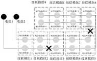
图3示出一种主从备份供电的显示系统,该方式下中间链路存在一项故障或者源端设备存在一项故障,系统可以正常工作;而当源端的供电设备存在两项故障或者链路存在两项故障或者源端设备与另外一路的链路存在故障则系统不能正常工作,且端子的数量加多、链路的复杂性较大,无法在有限的结构空间内布置。其中,对于应对供电链路的故障,若级联模组1与电源1、电源2之间的第一供电链路和第二供电链路,及两个相邻的级联模组之间的第一供电链路和第二供电链路采用两个独立的连接器连接,即整个显示系统存在两组独立的连接器,则仅在第一供电链路中的任意一个连接器出现故障且第二供电链路的任意一个连接器出现故障时,例如,如图3所示的第一供电链路中的级联模组2与级联模组3之间的连接器出现故障同时第二供电链路中的级联模组5和级联模组6之间的连接器出现故障,则级联模组6-级联模组7全部断电,系统将无法正常工作,但是,这种两组独立的连接器的方式,占用空间较大,不适用于走线空间受限的场景。而若级联模组1与电源1、电源2之间的第一供电链路和第二供电链路,及两个相邻的级联模组之间的第一供电链路和第二供电链路共用一个连接器,则如图4所示,任意一个连接器出现故障则第一供电链路和第二供电链路均出现中断,供电的稳定性和可靠性无法保障,例如图4所示,若级联模组2和级联模组3之间的连接器断开,则第一供电链路和第二供电链路均出现中断,导致级联模组4至级联模组9全部断电,系统将无法正常工作。Figure 3 shows a master-slave backup power supply display system. In this mode, there is one fault in the intermediate link or one fault in the source device, and the system can work normally; and when there are two faults in the power supply device at the source or the link If there are two faults in the circuit or the link between the source device and the other channel is faulty, the system cannot work normally, and the number of terminals increases and the complexity of the link is large, so it cannot be arranged in a limited structural space. Among them, for the failure of the power supply link, if the first power supply link and the second power supply link between the cascade module 1 and the power supply 1 and
有鉴于此,本发明实施例提供了一种显示系统,如图5和图6所示,包括:In view of this, an embodiment of the present invention provides a display system, as shown in FIG. 5 and FIG. 6 , including:
电源装置和N个级联模组,本实施例中,N为10,即显示系统包括10个级联模组,分别为级联模组1至级联模组10,电源装置包括电源1、电源2、第一供电链路和第二供电链路,电源1位于第一供电链路的源端,电源2位于第二供电链路的源端,级联模组1至级联模组10分别接入所述第一供电链路和所述第二供电链路,The power supply device and N cascade modules. In this embodiment, N is 10, that is, the display system includes 10 cascade modules, which are respectively cascade module 1 to cascade module 10. The power supply device includes power supply 1,
其中,第n个级联模组接入所述第一供电链路的接入位置相比于第n-1个级联模组接入所述第一供电链路的接入位置,远离所述第一供电链路的源端;第n个级联模组接入所述第二供电链路的接入位置相比于第n-1个级联模组接入所述第二供电链路的接入位置,靠近所述第二供电链路的源端;其中,n=2,…,10。Wherein, the access position where the nth cascading module is connected to the first power supply link is far away from the access position where the n-1th cascading module is connected to the first power supply link The source end of the first power supply chain; the access position of the nth cascading module connected to the second power supply chain is compared with the access position of the n-1th cascading module to the second power supply chain The access position of the road is close to the source end of the second power supply link; wherein, n=2,...,10.
在一种可能的实现方式中,第n-1个级联模组与第n个级联模组之间的第一供电链路和第二供电链路共用一个连接器。即,相邻级联模组间的第一供电线路和第二供电线路共用一个连接器,其中,需要说明的是,第一供电链路和第二供电链路为单独的集成线束。这样,可减少线路长度,减少对接端子的数量,从而可满足结构空间的限制。In a possible implementation manner, the first power supply link and the second power supply link between the n-1th cascading module and the nth cascading module share one connector. That is, the first power supply line and the second power supply line between adjacent cascading modules share one connector. It should be noted that the first power supply link and the second power supply link are separate integrated wire harnesses. In this way, the length of the line can be reduced and the number of butt terminals can be reduced, so that the limitation of the construction space can be met.
本实施例提供的显示系统,可以称为交叉环路备份供电的显示系统,其可在实现供电链路和电源的双备份,保证系统供电的稳定性和可靠性的同时,大幅缩减连接器数量,可适用于各种类型的包含多个待供电装置的系统,特别是例如拼接屏显示系统等走线空间受限的系统,具有广泛的应用前景和实用价值。与图3和4所示的主从备份供电方式不同的是,本实施例提供的采用交叉环路备份供电的显示系统,对于应对供电链路的故障,相邻级联模组之间的第一供电链路和第二供电链路可以共用一个连接器,因为,即使任意一个连接器故障,系统也可正常工作,只有两个连接器故障才会出现系无法正常工作的情况,采用本实施例提供的供电方案,即可在保证系统供电的稳定性、可靠性的同时,大幅缩减连接器数量。The display system provided in this embodiment can be referred to as a display system with cross-loop backup power supply, which can realize dual backup of the power supply link and power supply, ensure the stability and reliability of the power supply of the system, and greatly reduce the number of connectors. , which can be applied to various types of systems including multiple devices to be powered, especially systems with limited wiring space such as splicing screen display systems, and has broad application prospects and practical value. Different from the master-slave backup power supply modes shown in FIGS. 3 and 4 , the display system provided in this embodiment adopts the cross-loop backup power supply. The first power supply link and the second power supply link can share one connector, because even if any one of the connectors fails, the system can work normally, and only if two connectors fail will the system fail to work normally. The power supply solution provided by the example can greatly reduce the number of connectors while ensuring the stability and reliability of the system power supply.
在一种可能的实现方式中,电源1用于向所述第一供电链路输出第一电压信号,电源2用于向所述第二供电链路输出第二电压信号。In a possible implementation manner, the power supply 1 is configured to output a first voltage signal to the first power supply link, and the
在一种可能的实现方式中,所述级联模组包括电源模块和LED显示屏,其中,LED显示屏是拼接屏显示系统常用的显示屏,本实施例中,采用LED显示屏只是示例,本实施例提供的显示装置也可采用LCD显示屏、OLED显示屏等,不做特定限制,电源模块包括电压转换器和电压接收器;In a possible implementation manner, the cascading module includes a power module and an LED display screen, wherein the LED display screen is a commonly used display screen in a splicing screen display system. In this embodiment, the LED display screen is only an example. The display device provided in this embodiment can also use an LCD display screen, an OLED display screen, etc., without specific limitations, and the power supply module includes a voltage converter and a voltage receiver;
所述电压转换器的输入端分别接入所述第一供电链路和所述第二供电链路,所述电压转换器的输出端连接所述电压接收器的输入端,所述电压接收器的输出端连接所述功能组件的供电输入端。The input terminals of the voltage converter are respectively connected to the first power supply link and the second power supply link, and the output terminal of the voltage converter is connected to the input terminal of the voltage receiver, and the voltage receiver The output terminal is connected to the power supply input terminal of the functional component.
在一种可能的实现方式中,所述电压转换器包括第一电压转换器和第二电压转换器,所述电源模块还包括第一反向二极管和第二反向二极管;In a possible implementation manner, the voltage converter includes a first voltage converter and a second voltage converter, and the power module further includes a first reverse diode and a second reverse diode;
所述第一电压转换器的输入端接入所述第一供电链路,所述第二电压转换器的输入端接入所述第二供电链路;The input end of the first voltage converter is connected to the first power supply chain, and the input end of the second voltage converter is connected to the second power supply chain;
所述第一反向二极管的阳极连接所述第一电压转换器的输出端,所述第二反向二极管的阳极连接所述第二电压转换器的输出端;The anode of the first reverse diode is connected to the output end of the first voltage converter, and the anode of the second reverse diode is connected to the output end of the second voltage converter;
所述第一反向二极管的阴极与所述第二反向二极管的阴极连接,且分别连接所述电压接收器的输入端。The cathode of the first reverse diode is connected to the cathode of the second reverse diode, and is respectively connected to the input terminal of the voltage receiver.
在一种可能的实现方式中,所述电压接收器包括第一电压接收器和第二电压接收器;所述第一反向二极管的阴极和所述第二反向二极管的阴极,分别连接所述第一电压接收器的输入端和所述第二电压接收器的输入端;所述第一电压接收器的输出端和所述第二电压接收器的输出端分别连接所述功能组件的供电输入端。In a possible implementation manner, the voltage receiver includes a first voltage receiver and a second voltage receiver; the cathode of the first reverse diode and the cathode of the second reverse diode are connected to the The input end of the first voltage receiver and the input end of the second voltage receiver; the output end of the first voltage receiver and the output end of the second voltage receiver are respectively connected to the power supply of the functional components input.
本方案中的电压接收器通过反向二极管与电压转换器相连,从而避免元件被反向电压损坏,待供电装置分别接入第一供电链路和第二供电链路,若内部电路出现故障,极可能出现电压高的电源给电压低的电源供电,出现电源损坏的情况,使用反向二极管,可以保证电源和其他元件免遭损坏,进一步提高了系统的稳定性。In this solution, the voltage receiver is connected to the voltage converter through a reverse diode, so as to prevent the components from being damaged by the reverse voltage. The power supply devices are respectively connected to the first power supply link and the second power supply link. It is very likely that a high-voltage power supply supplies power to a low-voltage power supply, and the power supply is damaged. Using a reverse diode can ensure that the power supply and other components are not damaged, and further improve the stability of the system.
在一个具体的实施例中,所述第一电压信号和所述第二电压信号分别为直流电压信号,所述电压转换器为直流电压转换器(DC-DC)。In a specific embodiment, the first voltage signal and the second voltage signal are respectively direct current voltage signals, and the voltage converter is a direct current voltage converter (DC-DC).
在一种可能的实现方式中,所述第一电压信号与所述第二电压信号的设定值相同,所述第一电压转换器与所述第二电压转换器的参数相同。In a possible implementation manner, the set value of the first voltage signal and the second voltage signal are the same, and the parameters of the first voltage converter and the second voltage converter are the same.
在一个具体示例中,如图7所示的只包括3个级联模组的显示系统,包括:电源1、电源2、级联模组1、级联模组2和级联模组3,其中,级联模组1包括:电压转换器DC-DC111、电压转换器DC-DC112、反向二极管121、反向二极管122、接收卡131(接收卡即电压接收器)、接收卡132和LED显示屏141,级联模组2包括电压转换器DC-DC211、电压转换器DC-DC212、反向二极管221、反向二极管222、接收卡231、接收卡232和LED显示屏241,级联模组3包括电压转换器DC-DC311、电压转换器DC-DC312、反向二极管321、反向二极管322、接收卡331、接收卡332和LED显示屏341。In a specific example, as shown in FIG. 7 , the display system only includes three cascade modules, including: power supply 1,
下面以级联模组2为例对连接方式进行讲解:在该级联模组内部,包括由电压转换器DC-DC211、反向二极管221组成的电流通路和由电压转换器DC-DC212、反向二极管222组成的电流通路,电压转换器DC-DC211通过连接器在第一供电链路上与所述级联模组1连接以接收来自级联模组1的输入,其输出端与所述反向二极管221的阳极相连接,所述电压转换器DC-DC212的输入端通过供电端子接入第二供电链路中,所述第二供电链路上的相邻级联模组通过连接器连接,其输出端与反向二极管222的阳极连接,所述反向二极管221和反向二极管222的阴极连接且分别接入所述接收卡231和接收卡232的电源输入端,其中,The connection method is explained below by taking the cascading
级联模组2的电压转换器DC-DC211和电压转换器DC-DC212的输入分别从级联模组1和第级联模组3引入,级联模组1到级联模组2之间传输的为来自电源1的电信号,级联模组3到级联模组2传输的为来自电源2的电信号。The input of the voltage converter DC-DC211 and the voltage converter DC-DC212 of the cascading
接收卡231和接收卡232的电源输入均为经过电压转换器DC-DC211和电压转换器DC-DC212转换后再经反向二极管处理后输出的电压信号。The power inputs of the receiving card 231 and the receiving card 232 are voltage signals which are converted by the voltage converter DC-DC211 and the voltage converter DC-DC212 and then output by reverse diode processing.
在一个具体的实施例中,由于源端电源的差异性和直流电压转换器的差异性,第一电压转换器和第二电压转换器的输出电压存在差异,可能会存在其中一路输出电压大于另一路输出电压,可能出现电压高的电源给电压低的电源供电,出现电源损坏的情况,本方案中电压接收器通过反向二极管与电压转换器相连,从而避免元件被反向电压损坏,待供电装置分别接入第一供电链路和第二供电链路,若内部电路出现故障,也可以保证电源和其他元件免遭损坏,进一步提高了系统的稳定性。In a specific embodiment, due to the difference of the source power supply and the difference of the DC voltage converter, the output voltages of the first voltage converter and the second voltage converter are different, and there may be one output voltage greater than the other. With one output voltage, a high-voltage power supply may supply power to a low-voltage power supply, and the power supply may be damaged. In this solution, the voltage receiver is connected to the voltage converter through a reverse diode, so as to prevent the components from being damaged by reverse voltage. The device is respectively connected to the first power supply link and the second power supply link. If the internal circuit fails, the power supply and other components can also be protected from damage, which further improves the stability of the system.
基于图7所示的示例,对于图5和图6所示的显示系统,第n级联模组n与级联模组n-1和n+1的接入位置关系的简化示意如图8所示。Based on the example shown in FIG. 7 , for the display systems shown in FIG. 5 and FIG. 6 , a simplified schematic diagram of the access position relationship between the nth cascading module n and the cascading modules n-1 and n+1 is shown in FIG. 8 . shown.
所述第n个级联模组包括第一电压转换器DC-DCn11、第二电压转换器DC-DCn12、第一反向二极管n21、第二反向二极管n22、接收卡n31、接收卡n32以及LED显示屏n41,其中,The n th cascading module includes a first voltage converter DC-DCn11, a second voltage converter DC-DCn12, a first reverse diode n21, a second reverse diode n22, a receiving card n31, a receiving card n32 and LED display n41, of which,
第一电压转换器DC-DCn11的输入从第n-1个级联模组引入,第二电压转换器DC-DC212的输入从第n+1和级联模组引入。The input of the first voltage converter DC-DCn11 is introduced from the n-1th cascading module, and the input of the second voltage converter DC-DC212 is introduced from the n+1th cascading module.
在一个具体示例中,由于源端电源的差异性和DC-DC电压变换器的差异性,在DC-DC输出端的输出电压Uout1和Uout2的电压存在差异,可能会存在其中一个变换器的输出电压大于另外一个变换器的输出电压,以初始状态下第一电压转换器DC-DC1的输出电压Uout1大于第二电压转换器DC-DC2的输出电压Uout2为例进行分析:In a specific example, due to the difference of the source power supply and the difference of the DC-DC voltage converter, the output voltages Uout1 and Uout2 at the DC-DC output end are different, and there may be an output voltage of one of the converters. The output voltage of the first voltage converter DC-DC1 is greater than the output voltage Uout2 of the second voltage converter DC-DC2 in the initial state as an example for analysis:
如图9所示,为由于初始状态下Uout1的值较大,则级联模组的两个接收卡均由第一电压转换器的输出电压Uout1进行供电,随着供电功率的增加,电流的增大,Uout1的压降会增加,当接收卡的输出功率增加至P0,Uout2开始供电,第一电压转换器与第二电压转换器共同为接收卡进行供电。As shown in Figure 9, because the value of Uout1 is relatively large in the initial state, the two receiving cards of the cascade module are powered by the output voltage Uout1 of the first voltage converter. Increase, the voltage drop of Uout1 will increase. When the output power of the receiving card increases to P0 , Uout2 starts to supply power, and the first voltage converter and the second voltage converter jointly supply power to the receiving card.
具体的,当第n个级联模组的供电功率较低时,则由输出电压较高的第一电压转换器输出的Uout1对接收卡进行供电,此时第二电压转换器对电压接收卡的输出功率为0。Specifically, when the power supply of the nth cascading module is low, the Uout1 output by the first voltage converter with a high output voltage supplies power to the receiving card, and at this time, the second voltage converter supplies power to the voltage receiving card The output power is 0.
本领域技术人员能够了解的是,级联模组需要的供电功率较低的原因之一是级联模组中的LED显示屏显示亮度较小,这样,在接收卡的输出功率小于P0时,接收卡由单个电压转换器输出端的输出电压供电。Those skilled in the art can understand that one of the reasons why the power supply power required by the cascading module is low is that the LED display screen in the cascading module has low display brightness, so that when the output power of the receiving card is less than P0 , the receiving card is powered by the output voltage at the output of a single voltage converter.
在一个具体的实施例中,如图10所示,在上述两种工作模式下,若在t0时刻所述第n个级联模组的第一电压转换器DC-DCn11损坏、电源1损坏或者从第n-1个级联模组到第一电压转换器DC-DCn11之间的连接链路损坏时,则第一电压转换器DC-DCn11工作异常,其输出电压Uout1不再对接收卡进行供电,第二电压转换器DC-DCn12开启工作,第n个级联模组的电压接收,由第二电压转换器DC-DCn12进行供电。通过n+1个级联模组的电源输出端子为第n个级联模组的第二电压转换器DC-DCn12进行供电。In a specific embodiment, as shown in FIG. 10 , under the above two operating modes, if the first voltage converter DC-DCn11 of the nth cascade module is damaged and the power supply 1 is damaged at timet0 Or when the connection link from the n-1th cascading module to the first voltage converter DC-DCn11 is damaged, the first voltage converter DC-DCn11 works abnormally, and its output voltage Uout1 is no longer available to the receiving card. For power supply, the second voltage converter DC-DCn12 is turned on to work, and the voltage of the n-th cascaded module is received and powered by the second voltage converter DC-DCn12. Power is supplied to the second voltage converter DC-DCn12 of the nth cascading module through the power output terminals of the n+1 cascading modules.
具体的:specific:
若为级联模组的第一电压转换器损坏,则仅当前级联模组变更为由第二电压转换器为接收卡供电,其余级联模组依然可为第一电压转换器和第二电压转换器共同为接收卡供电或由第一电压转换器为接收卡供电;If the first voltage converter of the cascade module is damaged, only the current cascade module is changed to use the second voltage converter to supply power to the receiving card, and the remaining cascade modules can still be the first voltage converter and the second voltage converter. The voltage converters jointly supply power to the receiving card or the first voltage converter supplies power to the receiving card;
若为电源1损坏,则所有级联模组均由第二电源器进行供电,电源2通过第二供电链路为每个级联模组的第二电压转换器供电,由所述第二电压转换器输出的电压信号Uout2为级联模组的接收卡供电,拼接显示系统中的每个LED显示屏均能正常显示,系统正常运行;If the power supply 1 is damaged, all the cascade modules are powered by the second power supply, and the
若为第一供电链路中第n-1个至第n个级联模组之间的连接器出现问题,由于相邻两个级联模组之间的第一供电链路和第二供电链路共用一个连接器,相当于第n-1个级联模组和第n个级联模组之间的连接通路断开,则第1个至第n-1个级联模组由第一电压转换器为接收卡供电,由所述第一电压转换器输出的电压信号Uout1为所述第1个至n-1个级联模组的接收卡供电;第n个至第N个级联模组为由第二电压转换器为接收卡供电,由所述第二电压转换器输出的电压信号Uout2为所述第n个至第N个级联模组的接收卡供电,拼接显示系统中的每个LED显示屏均能正常显示,系统正常运行。If there is a problem with the connector between the n-1th to nth cascading modules in the first power supply chain, because the first power supply link and the second power supply between the two adjacent cascading modules The link shares one connector, which means that the connection path between the n-1th cascading module and the nth cascading module is disconnected. A voltage converter supplies power to the receiving card, and the voltage signal Uout1 output by the first voltage converter supplies power to the receiving cards of the first to n-1 cascaded modules; the nth to Nth stages The connecting module is powered by the second voltage converter to supply power to the receiving card, and the voltage signal Uout2 output by the second voltage converter supplies power to the receiving cards of the nth to Nth cascade modules, and the splicing display system Each LED display in the display can be displayed normally, and the system is running normally.
在一个具体的实施例中,若第二电压转换器DC-DC2损坏或者第二供电链路中从第n+1个级联模组到第n个级联模组之间的连接链路损坏时,则其第一电压转换器DC-DC1开启工作,通过第一供电链路中第n-1个级联模组的电源输出端子为第n个级联模组的第一电压转换器DC-DC1进行供电。此时,第1~n个级联模组的接收卡均由第一电压转换器DC-DC1进行供电,第n+1~N个级联模组的接收卡均由第二电压转换器DC-DC2进行供电。In a specific embodiment, if the second voltage converter DC-DC2 is damaged or the connection link from the n+1th cascade module to the nth cascade module in the second power supply link is damaged , then its first voltage converter DC-DC1 is turned on, and the power output terminal of the n-1th cascade module in the first power supply chain is the first voltage converter DC of the nth cascade module -DC1 for power supply. At this time, the receiving cards of the 1st to nth cascade modules are powered by the first voltage converter DC-DC1, and the receiving cards of the n+1th to Nth cascade modules are all powered by the second voltage converter DC -DC2 for power supply.
为了更清楚的说明本实施例,下面以包括多个级联模组的拼接屏显示系统为例,在该拼接屏显示系统内部,包含两路供电链路、多个级联模组,所述多个级联模组外接于所述供电链路的供电端子,相邻两级联模组之间的第一供电链路和第二供电链路通过同一连接器相连接,第一电源和第二电源分别位于所述第一供电电路和第二供电电路的源端,In order to explain this embodiment more clearly, the following takes a splicing screen display system including a plurality of cascade modules as an example. Inside the splicing screen display system, it includes two power supply links and a plurality of cascade modules. A plurality of cascade modules are externally connected to the power supply terminals of the power supply links, the first power supply link and the second power supply link between two adjacent cascade modules are connected through the same connector, and the first power supply and the second power supply link are connected through the same connector. Two power sources are respectively located at the source ends of the first power supply circuit and the second power supply circuit,
第一电源的输出电压信号依次经过第一供电链路上第1个至第N个级联模组与连接器,形成第一电流通路;The output voltage signal of the first power supply sequentially passes through the first to Nth cascade modules and connectors on the first power supply link to form a first current path;
第二电源的输出电压信号依次经过第二供电链路上第1个至第N个级联模组和连接器,形成第二电流通路。The output voltage signal of the second power supply sequentially passes through the first to Nth cascading modules and connectors on the second power supply chain to form a second current path.
在本发明的描述中,需要说明的是,术语“上”、“下”等指示的方位或位置关系为基于附图所示的方位或位置关系,仅是为了便于描述本发明和简化描述,而不是指示或暗示所指的装置或元件必须具有特定的方位、以特定的方位构造和操作,因此不能理解为对本发明的限制。除非另有明确的规定和限定,术语“安装”、“相连”、“连接”应做广义理解,例如,可以是固定连接,也可以是可拆卸连接,或一体地连接;可以是机械连接,也可以是电连接;可以是直接相连,也可以通过中间媒介间接相连,可以是两个元件内部的连通。对于本领域的普通技术人员而言,可以根据具体情况理解上述术语在本发明中的具体含义。In the description of the present invention, it should be noted that the orientation or positional relationship indicated by the terms "upper", "lower", etc. is based on the orientation or positional relationship shown in the accompanying drawings, and is only for the convenience of describing the present invention and simplifying the description, It is not intended to indicate or imply that the device or element referred to must have a particular orientation, be constructed and operate in a particular orientation, and therefore should not be construed as limiting the invention. Unless otherwise expressly specified and limited, the terms "installed", "connected" and "connected" should be understood in a broad sense, for example, it may be a fixed connection, a detachable connection, or an integral connection; it may be a mechanical connection, It can also be an electrical connection; it can be a direct connection, an indirect connection through an intermediate medium, or an internal connection between two components. For those of ordinary skill in the art, the specific meanings of the above terms in the present invention can be understood according to specific situations.
还需要说明的是,在本发明的描述中,诸如第一和第二等之类的关系术语仅仅用来将一个实体或者操作与另一个实体或操作区分开来,而不一定要求或者暗示这些实体或操作之间存在任何这种实际的关系或者顺序。而且,术语“包括”、“包含”或者其任何其他变体意在涵盖非排他性的包含,从而使得包括一系列要素的过程、方法、物品或者设备不仅包括那些要素,而且还包括没有明确列出的其他要素,或者是还包括为这种过程、方法、物品或者设备所固有的要素。在没有更多限制的情况下,由语句“包括一个……”限定的要素,并不排除在包括所述要素的过程、方法、物品或者设备中还存在另外的相同要素。It should also be noted that, in the description of the present invention, relational terms such as first and second, etc. are only used to distinguish one entity or operation from another entity or operation, and do not necessarily require or imply these There is no such actual relationship or sequence between entities or operations. Moreover, the terms "comprising", "comprising" or any other variation thereof are intended to encompass non-exclusive inclusion such that a process, method, article or device comprising a list of elements includes not only those elements, but also includes not explicitly listed or other elements inherent to such a process, method, article or apparatus. Without further limitation, an element qualified by the phrase "comprising a..." does not preclude the presence of additional identical elements in a process, method, article or apparatus that includes the element.
显然,本发明的上述实施例仅仅是为清楚地说明本发明所作的举例,而并非是对本发明的实施方式的限定,对于本领域的普通技术人员来说,在上述说明的基础上还可以做出其它不同形式的变化或变动,这里无法对所有的实施方式予以穷举,凡是属于本发明的技术方案所引伸出的显而易见的变化或变动仍处于本发明的保护范围之列。Obviously, the above-mentioned embodiments of the present invention are only examples for clearly illustrating the present invention, rather than limiting the embodiments of the present invention. Changes or changes in other different forms cannot be exhausted here, and all obvious changes or changes derived from the technical solutions of the present invention are still within the protection scope of the present invention.
Claims (10)
Priority Applications (1)
| Application Number | Priority Date | Filing Date | Title |
|---|---|---|---|
| CN202210308489.3ACN114709915A (en) | 2022-03-28 | 2022-03-28 | Power supply guarantee system |
Applications Claiming Priority (1)
| Application Number | Priority Date | Filing Date | Title |
|---|---|---|---|
| CN202210308489.3ACN114709915A (en) | 2022-03-28 | 2022-03-28 | Power supply guarantee system |
Publications (1)
| Publication Number | Publication Date |
|---|---|
| CN114709915Atrue CN114709915A (en) | 2022-07-05 |
Family
ID=82170899
Family Applications (1)
| Application Number | Title | Priority Date | Filing Date |
|---|---|---|---|
| CN202210308489.3APendingCN114709915A (en) | 2022-03-28 | 2022-03-28 | Power supply guarantee system |
Country Status (1)
| Country | Link |
|---|---|
| CN (1) | CN114709915A (en) |
Citations (5)
| Publication number | Priority date | Publication date | Assignee | Title |
|---|---|---|---|---|
| KR20090079097A (en)* | 2008-01-16 | 2009-07-21 | 티피케이 터치 솔루션스 인코포레이션 | Dual power supply system using circuit loop switching control circuit |
| CN201789332U (en)* | 2010-08-06 | 2011-04-06 | 深圳市金威源科技股份有限公司 | Power supply system of communication base station |
| CN205335966U (en)* | 2015-12-25 | 2016-06-22 | 瑞斯康达科技发展股份有限公司 | Power standby system |
| CN210776573U (en)* | 2019-11-21 | 2020-06-16 | 苏州浪潮智能科技有限公司 | Multi-power-supply plane power supply device |
| CN113541300A (en)* | 2021-07-06 | 2021-10-22 | 浙江大华技术股份有限公司 | Power supply redundancy backup control circuit and LED display system |
- 2022
- 2022-03-28CNCN202210308489.3Apatent/CN114709915A/enactivePending
Patent Citations (5)
| Publication number | Priority date | Publication date | Assignee | Title |
|---|---|---|---|---|
| KR20090079097A (en)* | 2008-01-16 | 2009-07-21 | 티피케이 터치 솔루션스 인코포레이션 | Dual power supply system using circuit loop switching control circuit |
| CN201789332U (en)* | 2010-08-06 | 2011-04-06 | 深圳市金威源科技股份有限公司 | Power supply system of communication base station |
| CN205335966U (en)* | 2015-12-25 | 2016-06-22 | 瑞斯康达科技发展股份有限公司 | Power standby system |
| CN210776573U (en)* | 2019-11-21 | 2020-06-16 | 苏州浪潮智能科技有限公司 | Multi-power-supply plane power supply device |
| CN113541300A (en)* | 2021-07-06 | 2021-10-22 | 浙江大华技术股份有限公司 | Power supply redundancy backup control circuit and LED display system |
Similar Documents
| Publication | Publication Date | Title |
|---|---|---|
| CN103472740B (en) | Power Supplier | |
| US9679515B2 (en) | LED driving circuit and control system | |
| CN110992861B (en) | Display panel and display device | |
| US11561591B2 (en) | LED display driven by dual-negative-voltage power supply | |
| US11145439B2 (en) | Display device, and insertion and plugging protection device | |
| US20140070616A1 (en) | Power conversion output architecture | |
| US20150102990A1 (en) | Gate driving circuit, and array substrate and display panel thereof | |
| US9979114B2 (en) | Connector, socket, method for providing signals to connector by socket, electronic equipment | |
| CN107610664B (en) | Circuit board and display | |
| US7843083B2 (en) | Backup power system equipped with independent protection circuit architecture | |
| CN114709915A (en) | Power supply guarantee system | |
| CN112639601A (en) | Dual-function circuit, display panel, test method of display panel and electrostatic protection method of display panel | |
| CN216905398U (en) | LED lamp detection circuit and LED lamp driving system | |
| CN102854964A (en) | Electronic equipment | |
| US11083065B2 (en) | Driving circuit device for anti-leakage LED tube with dual-end input | |
| EP2487776A2 (en) | Subsidiary power source for bidirectional power supply | |
| US20150137690A1 (en) | Power supply module for energy saving lamp | |
| CN102186293A (en) | Power supply conversion circuit of light emitting diode | |
| US10148192B1 (en) | Power supply system and control method using the same | |
| CN111724723A (en) | Aging device | |
| CN111739460A (en) | Display control device and display system | |
| US20140013130A1 (en) | Expansion circuit for server system and server system using same | |
| CN105990899B (en) | Power module and bridging device thereof | |
| CN117392951B (en) | Power supply detection circuit, silicon-based display panel and display device | |
| CN223451809U (en) | Energy storage cabinet and power converter |
Legal Events
| Date | Code | Title | Description |
|---|---|---|---|
| PB01 | Publication | ||
| PB01 | Publication | ||
| SE01 | Entry into force of request for substantive examination | ||
| SE01 | Entry into force of request for substantive examination |