CN114699089A - Electroencephalogram detection device, impedance detection method, and storage medium - Google Patents
Electroencephalogram detection device, impedance detection method, and storage mediumDownload PDFInfo
- Publication number
- CN114699089A CN114699089ACN202210359138.5ACN202210359138ACN114699089ACN 114699089 ACN114699089 ACN 114699089ACN 202210359138 ACN202210359138 ACN 202210359138ACN 114699089 ACN114699089 ACN 114699089A
- Authority
- CN
- China
- Prior art keywords
- eeg
- signal
- impedance
- detection device
- processing unit
- Prior art date
- Legal status (The legal status is an assumption and is not a legal conclusion. Google has not performed a legal analysis and makes no representation as to the accuracy of the status listed.)
- Granted
Links
Images


Classifications
- A—HUMAN NECESSITIES
- A61—MEDICAL OR VETERINARY SCIENCE; HYGIENE
- A61B—DIAGNOSIS; SURGERY; IDENTIFICATION
- A61B5/00—Measuring for diagnostic purposes; Identification of persons
- A61B5/24—Detecting, measuring or recording bioelectric or biomagnetic signals of the body or parts thereof
- A61B5/316—Modalities, i.e. specific diagnostic methods
- A61B5/369—Electroencephalography [EEG]
- A—HUMAN NECESSITIES
- A61—MEDICAL OR VETERINARY SCIENCE; HYGIENE
- A61B—DIAGNOSIS; SURGERY; IDENTIFICATION
- A61B5/00—Measuring for diagnostic purposes; Identification of persons
- A61B5/05—Detecting, measuring or recording for diagnosis by means of electric currents or magnetic fields; Measuring using microwaves or radio waves
- A61B5/053—Measuring electrical impedance or conductance of a portion of the body
- A61B5/0531—Measuring skin impedance
- A—HUMAN NECESSITIES
- A61—MEDICAL OR VETERINARY SCIENCE; HYGIENE
- A61B—DIAGNOSIS; SURGERY; IDENTIFICATION
- A61B5/00—Measuring for diagnostic purposes; Identification of persons
- A61B5/24—Detecting, measuring or recording bioelectric or biomagnetic signals of the body or parts thereof
- A61B5/25—Bioelectric electrodes therefor
- A61B5/279—Bioelectric electrodes therefor specially adapted for particular uses
- A61B5/291—Bioelectric electrodes therefor specially adapted for particular uses for electroencephalography [EEG]
- A—HUMAN NECESSITIES
- A61—MEDICAL OR VETERINARY SCIENCE; HYGIENE
- A61B—DIAGNOSIS; SURGERY; IDENTIFICATION
- A61B5/00—Measuring for diagnostic purposes; Identification of persons
- A61B5/72—Signal processing specially adapted for physiological signals or for diagnostic purposes
- A61B5/7225—Details of analogue processing, e.g. isolation amplifier, gain or sensitivity adjustment, filtering, baseline or drift compensation
- A—HUMAN NECESSITIES
- A61—MEDICAL OR VETERINARY SCIENCE; HYGIENE
- A61B—DIAGNOSIS; SURGERY; IDENTIFICATION
- A61B5/00—Measuring for diagnostic purposes; Identification of persons
- A61B5/72—Signal processing specially adapted for physiological signals or for diagnostic purposes
- A61B5/7235—Details of waveform analysis
- A61B5/725—Details of waveform analysis using specific filters therefor, e.g. Kalman or adaptive filters
Landscapes
- Health & Medical Sciences (AREA)
- Life Sciences & Earth Sciences (AREA)
- Engineering & Computer Science (AREA)
- General Health & Medical Sciences (AREA)
- Public Health (AREA)
- Veterinary Medicine (AREA)
- Animal Behavior & Ethology (AREA)
- Surgery (AREA)
- Physics & Mathematics (AREA)
- Molecular Biology (AREA)
- Biophysics (AREA)
- Pathology (AREA)
- Biomedical Technology (AREA)
- Heart & Thoracic Surgery (AREA)
- Medical Informatics (AREA)
- Signal Processing (AREA)
- Psychiatry (AREA)
- Physiology (AREA)
- Artificial Intelligence (AREA)
- Computer Vision & Pattern Recognition (AREA)
- Power Engineering (AREA)
- Dermatology (AREA)
- Nuclear Medicine, Radiotherapy & Molecular Imaging (AREA)
- Radiology & Medical Imaging (AREA)
- Psychology (AREA)
- Measurement And Recording Of Electrical Phenomena And Electrical Characteristics Of The Living Body (AREA)
Abstract
Description
Translated fromChinese技术领域technical field
本发明涉及医疗领域中用于检测脑电信号的脑电检测装置,具体涉及一种脑电检测装置、阻抗检测方法和存储介质。The invention relates to an EEG detection device used for detecting EEG signals in the medical field, in particular to an EEG detection device, an impedance detection method and a storage medium.
背景技术Background technique
活体人体组织细胞始终产生很微弱的生物电,脑电信号是由大量脑神经细胞在高度相干状态下的电活动在大脑皮层上的总体效应,利用在头皮上安放的电极将脑细胞的电活动引出来并经脑电检测设备放大后作分析和记录,它包含一定波形、波幅、频率和相位且是变化的,即为脑电图分析。当脑组织发生功能性改变时,这种波形曲线会发生相应的改变,从而为临床诊断、治病提供依据。Living human tissue cells always produce very weak bioelectricity. The EEG signal is the overall effect of the electrical activity of a large number of brain nerve cells in a highly coherent state on the cerebral cortex. Electrodes placed on the scalp are used to convert the electrical activity of brain cells. It is extracted and amplified by EEG detection equipment for analysis and recording. It contains certain waveforms, amplitudes, frequencies and phases and changes, that is, EEG analysis. When functional changes occur in brain tissue, this waveform curve will change accordingly, thus providing a basis for clinical diagnosis and treatment.
由于脑电信号本身十分微弱,在测量过程中难免有各种外界因素导致的伪差和噪声影响脑电信号的质量。电极与头皮接触不良引起的干扰和工频干扰以及放大通道噪声是脑电检测中三个影响最大的干扰来源。一些传统脑电检测设备不具有监测电极连接情况的功能,另有一些只能部分测量导联电极连接情况,没办法作到测量全部的导联电极连接。Since the EEG signal itself is very weak, it is inevitable that artifacts and noises caused by various external factors will affect the quality of the EEG signal during the measurement process. Interference caused by poor contact between electrodes and scalp, power frequency interference and amplified channel noise are the three most influential sources of interference in EEG detection. Some traditional EEG detection equipment does not have the function of monitoring electrode connection, and some can only partially measure the connection of lead and electrode, and cannot measure all the connection of lead and electrode.
发明内容SUMMARY OF THE INVENTION
本发明提供了一种脑电检测装置、阻抗检测方法和存储介质,旨在解决脑电信号的处理结果不稳定的技术问题。The present invention provides an EEG detection device, an impedance detection method and a storage medium, aiming at solving the technical problem of unstable EEG signal processing results.
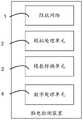
为实现上述目的,本发明提供了一种脑电检测装置,该脑电检测装置包括阻抗网络、模拟处理单元、模拟处理单元、模数转换单元和数字处理单元;所述阻抗网络的信号输出端与所述模拟处理单元的信号输入端电连接,所述阻抗网络的受驱动端与所述模拟处理单元的驱动端电连接,所述模拟处理单元的信号输出端与所述模数转换单元的信号输入端电连接,所述模数转换单元的信号输出端与所述数字处理单元的信号输入端相连接,所述模拟处理单元串接在所述阻抗网络的信号输出端和所述模拟处理单元的信号输入端之间,所述模拟处理单元的受控端与所述数字处理单元的控制端电连接。In order to achieve the above purpose, the present invention provides an EEG detection device, the EEG detection device includes an impedance network, an analog processing unit, an analog processing unit, an analog-to-digital conversion unit and a digital processing unit; the signal output end of the impedance network It is electrically connected to the signal input terminal of the analog processing unit, the driven terminal of the impedance network is electrically connected to the driving terminal of the analog processing unit, and the signal output terminal of the analog processing unit is electrically connected to the analog-to-digital conversion unit. The signal input end is electrically connected, the signal output end of the analog-to-digital conversion unit is connected with the signal input end of the digital processing unit, and the analog processing unit is connected in series with the signal output end of the impedance network and the analog processing unit Between the signal input terminals of the unit, the controlled terminal of the analog processing unit is electrically connected to the control terminal of the digital processing unit.
进一步地,所述脑电检测装置还包括辅助电路单元,所述辅助电路单元串接在所述阻抗网络和所述模拟处理单元之间。Further, the EEG detection device further includes an auxiliary circuit unit, and the auxiliary circuit unit is connected in series between the impedance network and the analog processing unit.
可选地,所述脑电检测装置还包括电源模块,所述电源模块包括:Optionally, the EEG detection device further includes a power supply module, and the power supply module includes:
正电源,所述正电源为恒流源,与所述模拟处理单元连接;a positive power supply, which is a constant current source and is connected to the analog processing unit;
负电源,所述负电源为恒流源,与所述模拟处理单元连接。A negative power supply, which is a constant current source, connected to the analog processing unit.
进一步地,所述数字处理单元包括:Further, the digital processing unit includes:
开关控制子单元,与所述模拟处理单元的受控端电连接;a switch control subunit, electrically connected to the controlled end of the analog processing unit;
阻抗检测子单元,与所述模数转换单元的信号输出端电连接,包括相互连接的测试信号滤波器和阻抗计算器;an impedance detection subunit, electrically connected to the signal output end of the analog-to-digital conversion unit, including a test signal filter and an impedance calculator connected to each other;
脑电信号处理子单元,与所述模数转换单元的信号输出端电连接,包括相互连接的脑电信号滤波器和脑电信号处理器。The EEG signal processing subunit is electrically connected to the signal output end of the analog-to-digital conversion unit, and includes an EEG signal filter and an EEG signal processor that are connected to each other.
具体地,所述模拟处理单元包括滤波放大电路和驱动电路,所述滤波放大电路的信号输入端与所述阻抗网络的信号输入端连接,所述滤波放大电路的信号输出端与所述模数转换单元的信号输入端连接,所述驱动电路的驱动端与所述阻抗网络的受驱动端连接。Specifically, the analog processing unit includes a filter amplifying circuit and a driving circuit, the signal input end of the filter amplifying circuit is connected to the signal input end of the impedance network, and the signal output end of the filter amplifying circuit is connected to the analog-digital The signal input end of the conversion unit is connected, and the driving end of the driving circuit is connected with the driven end of the impedance network.
具体地,所述阻抗网络包括至少两个脑电信号测试电极,阻抗测试辅助电极和驱动辅助电极,所述脑电信号测试电极分别与所述滤波放大电路的信号输入端连接,所述阻抗测试辅助电极与所述滤波放大电路的信号输入端连接,所述驱动辅助电极与所述驱动电路的驱动端连接。Specifically, the impedance network includes at least two EEG signal test electrodes, an impedance test auxiliary electrode and a driving auxiliary electrode, and the EEG signal test electrodes are respectively connected to the signal input ends of the filter and amplifier circuit. The auxiliary electrode is connected to the signal input end of the filter and amplifier circuit, and the drive auxiliary electrode is connected to the drive end of the drive circuit.
进一步地,所述模拟处理单元包括至少两组信号测试开关,所述信号测试开关与所述脑电信号测试电极一一对应,所述信号测试开关包括第一信号测试开关和第二信号测试开关,所述第一信号测试开关的一端与所述脑电信号测试电极的信号输出端连接,所述第一信号测试开关的另一端与所述正电源连接;所述第二信号测试开关的一端与所述脑电信号测试电极的信号输出端连接,所述第二信号测试开关的另一端与所述负电源连接。Further, the analog processing unit includes at least two groups of signal test switches, the signal test switches are in one-to-one correspondence with the EEG signal test electrodes, and the signal test switches include a first signal test switch and a second signal test switch. , one end of the first signal test switch is connected to the signal output end of the EEG signal test electrode, the other end of the first signal test switch is connected to the positive power supply; one end of the second signal test switch It is connected with the signal output end of the EEG signal test electrode, and the other end of the second signal test switch is connected with the negative power supply.
为了实现上述目的,本申请还提出一种脑电检测装置的阻抗检测方法,该脑电检测装置的阻抗检测方法的步骤包括:In order to achieve the above purpose, the present application also proposes an impedance detection method of an EEG detection device, and the steps of the impedance detection method of the EEG detection device include:
若处于脑电采集模式采集脑电信号,并根据所述脑电信号生成脑电信号处理结果;If in the EEG acquisition mode, collect EEG signals, and generate EEG signal processing results according to the EEG signals;
若处于阻抗检测模式,则获取电源测试信号,根据所述电源测试信号生成阻抗检测信号,并基于所述阻抗检测信号获取理论接触阻抗。If in the impedance detection mode, a power supply test signal is acquired, an impedance detection signal is generated according to the power supply test signal, and a theoretical contact impedance is acquired based on the impedance detection signal.
可选地,获取电流源的电流波幅和电路放大增益;Optionally, obtain the current amplitude and circuit amplification gain of the current source;
根据所述电流波幅、所述电路放大增益和所述阻抗检测信号计算理论接触阻抗。The theoretical contact impedance is calculated according to the current amplitude, the circuit amplification gain and the impedance detection signal.
为实现上述目的,本申请还提出一种存储介质,所述存储介质上存储有脑电检测装置的阻抗检测程序,所述脑电检测装置的阻抗检测程序被处理器执行时实现所述脑电检测装置。In order to achieve the above object, the present application also proposes a storage medium, on which an impedance detection program of an EEG detection device is stored, and the impedance detection program of the EEG detection device is executed by a processor to realize the EEG. detection device.
在本申请中,提供了一种脑电检测装置,由于该脑电检测装置包括相互连接的阻抗网络、模拟处理单元、模拟处理单元、模数转换单元和数字处理单元,通过上述脑电检测装置能够完成脑电信号的处理,以及装置内部阻抗的检测,从而保证对脑电信号的采集和处理的结果稳定可靠。In the present application, an EEG detection device is provided. Since the EEG detection device includes an impedance network, an analog processing unit, an analog processing unit, an analog-to-digital conversion unit, and a digital processing unit that are connected to each other, the EEG detection device can It can complete the processing of the EEG signal and the detection of the internal impedance of the device, so as to ensure the stable and reliable results of the collection and processing of the EEG signal.
附图说明Description of drawings
为了更清楚地说明本发明实施例或现有技术中的技术方案,下面将对实施例或现有技术描述中所需要使用的附图作简单地介绍,显而易见地,下面描述中的附图仅仅是本发明的一些实施例,对于本领域普通技术人员来讲,在不付出创造性劳动的前提下,还可以根据这些附图示出的结构获得其他的附图。In order to explain the embodiments of the present invention or the technical solutions in the prior art more clearly, the following briefly introduces the accompanying drawings that need to be used in the description of the embodiments or the prior art. Obviously, the accompanying drawings in the following description are only These are some embodiments of the present invention, and for those of ordinary skill in the art, other drawings can also be obtained according to the structures shown in these drawings without creative efforts.
图1为本发明一实施例的脑电检测装置的模块结构示意图;FIG. 1 is a schematic structural diagram of a module of an EEG detection device according to an embodiment of the present invention;
图2为本发明另一实施例的脑电检测装置的模块结构示意图;2 is a schematic structural diagram of a module of an EEG detection device according to another embodiment of the present invention;
图3为本发明又一实施例的脑电检测装置的模块结构示意图;3 is a schematic structural diagram of a module of an EEG detection device according to another embodiment of the present invention;
图4为本发明还一实施例的脑电检测装置的模块结构示意图;4 is a schematic structural diagram of a module of an EEG detection device according to another embodiment of the present invention;
图5为本发明一实施例的脑电检测装置的阻抗检测方法的流程图;5 is a flowchart of an impedance detection method of an EEG detection device according to an embodiment of the present invention;
图6为本发明一实施例的脑电检测装置的电路示意图。FIG. 6 is a schematic circuit diagram of an EEG detection device according to an embodiment of the present invention.
附图标号说明:Description of reference numbers:


本发明目的的实现、功能特点及优点将结合实施例,参照附图做进一步说明。The realization, functional characteristics and advantages of the present invention will be further described with reference to the accompanying drawings in conjunction with the embodiments.
具体实施方式Detailed ways
下面将结合本发明实施例中的附图,对本发明实施例中的技术方案进行清楚、完整地描述,显然,所描述的实施例仅仅是本发明的一部分实施例,而不是全部的实施例。基于本发明中的实施例,本领域普通技术人员在没有作出创造性劳动前提下所获得的所有其他实施例,都属于本发明保护的范围。The technical solutions in the embodiments of the present invention will be clearly and completely described below with reference to the accompanying drawings in the embodiments of the present invention. Obviously, the described embodiments are only a part of the embodiments of the present invention, not all of the embodiments. Based on the embodiments of the present invention, all other embodiments obtained by those of ordinary skill in the art without creative efforts shall fall within the protection scope of the present invention.
需要说明,本发明实施例中所有方向性指示(诸如上、下、左、右、前、后……)仅用于解释在某一特定姿态(如附图所示)下各部件之间的相对位置关系、运动情况等,如果该特定姿态发生改变时,则该方向性指示也相应地随之改变。It should be noted that all directional indications (such as up, down, left, right, front, back, etc.) in the embodiments of the present invention are only used to explain the relationship between various components under a certain posture (as shown in the accompanying drawings). The relative positional relationship, the movement situation, etc., if the specific posture changes, the directional indication also changes accordingly.
另外,在本发明中如涉及“第一”、“第二”等的描述仅用于描述目的,而不能理解为指示或暗示其相对重要性或者隐含指明所指示的技术特征的数量。由此,限定有“第一”、“第二”的特征可以明示或者隐含地包括至少一个该特征。在本发明的描述中,“多个”的含义是至少两个,例如两个,三个等,除非另有明确具体的限定。In addition, descriptions such as "first", "second", etc. in the present invention are only for descriptive purposes, and should not be construed as indicating or implying their relative importance or implicitly indicating the number of indicated technical features. Thus, a feature delimited with "first", "second" may expressly or implicitly include at least one of that feature. In the description of the present invention, "plurality" means at least two, such as two, three, etc., unless otherwise expressly and specifically defined.
在本发明中,除非另有明确的规定和限定,术语“连接”、“固定”等应做广义理解,例如,“固定”可以是固定连接,也可以是可拆卸连接,或成一体;可以是机械连接,也可以是电连接;可以是直接相连,也可以通过中间媒介间接相连,可以是两个元件内部的连通或两个元件的相互作用关系,除非另有明确的限定。对于本领域的普通技术人员而言,可以根据具体情况理解上述术语在本发明中的具体含义。In the present invention, unless otherwise expressly specified and limited, the terms "connected", "fixed" and the like should be understood in a broad sense, for example, "fixed" may be a fixed connection, a detachable connection, or an integrated; It can be a mechanical connection or an electrical connection; it can be a direct connection or an indirect connection through an intermediate medium, and it can be an internal communication between two elements or an interaction relationship between the two elements, unless otherwise explicitly defined. For those of ordinary skill in the art, the specific meanings of the above terms in the present invention can be understood according to specific situations.
另外,本发明各个实施例之间的技术方案可以相互结合,但是必须是以本领域普通技术人员能够实现为基础,当技术方案的结合出现相互矛盾或无法实现时应当认为这种技术方案的结合不存在,也不在本发明要求的保护范围之内。In addition, the technical solutions between the various embodiments of the present invention can be combined with each other, but must be based on the realization by those of ordinary skill in the art. When the combination of technical solutions is contradictory or cannot be achieved, it should be considered that the combination of technical solutions does not exist and is not within the scope of protection claimed by the present invention.
根据上述硬件结构,提出本发明方法各个实施例。According to the above hardware structure, various embodiments of the method of the present invention are proposed.
活体人体组织细胞始终产生很微弱的生物电,脑电信号是由大量脑神经细胞在高度相干状态下的电活动在大脑皮层上的总体效应,利用在头皮上安放的电极将脑细胞的电活动引出来并经脑电检测设备放大后作分析和记录,它包含一定波形、波幅、频率和相位且是变化的,即为脑电图分析。当脑组织发生功能性改变时,这种波形曲线会发生相应的改变,从而为临床诊断、治病提供依据。Living human tissue cells always produce very weak bioelectricity. The EEG signal is the overall effect of the electrical activity of a large number of brain nerve cells in a highly coherent state on the cerebral cortex. Electrodes placed on the scalp are used to convert the electrical activity of brain cells. It is extracted and amplified by EEG detection equipment for analysis and recording. It contains certain waveforms, amplitudes, frequencies and phases and changes, that is, EEG analysis. When functional changes occur in brain tissue, this waveform curve will change accordingly, thus providing a basis for clinical diagnosis and treatment.
由于脑电信号本身十分微弱,在测量过程中难免有各种外界因素导致的伪差和噪声影响脑电信号的质量。电极与头皮接触不良引起的干扰和工频干扰以及放大通道噪声是脑电检测中三个影响最大的干扰来源。一些传统脑电检测设备不具有监测电极连接情况的功能,另有一些只能部分测量导联电极连接情况,没办法作到测量全部的导联电极连接。Since the EEG signal itself is very weak, it is inevitable that artifacts and noises caused by various external factors will affect the quality of the EEG signal during the measurement process. Interference caused by poor contact between electrodes and scalp, power frequency interference and amplified channel noise are the three most influential sources of interference in EEG detection. Some traditional EEG detection equipment does not have the function of monitoring electrode connection, and some can only partially measure the connection of lead and electrode, and cannot measure all the connection of lead and electrode.
为了解决上述问题,本申请提出了一种脑电检测装置,参照图2,在本发明脑电检测装置的第一实施例中,所述脑电检测装置包括:阻抗网络1、模拟处理单元2、模数转换单元3和数字处理单元4;所述阻抗网络1的信号输出端与所述模拟处理单元2的信号输入端电连接,所述阻抗网络1的受驱动端与所述模拟处理单元2的驱动端电连接,所述模拟处理单元的信号输出端与所述模数转换单元3的信号输入端电连接,所述模数转换单元3的信号输出端与所述数字处理单元4的信号输入端相连接,所述模拟处理单元串接在所述阻抗网络1的信号输出端和所述模拟处理单元2的信号输入端之间,所述模拟处理单元的受控端与所述数字处理单元4的控制端电连接。In order to solve the above problems, the present application proposes an EEG detection device. Referring to FIG. 2 , in the first embodiment of the EEG detection device of the present invention, the EEG detection device includes: an impedance network 1 and an
本实施例中,脑电检测装置包括:阻抗网络1、模拟处理单元、模拟处理单元2、模数转换单元3和数字处理单元4。其中,阻抗网络1包括至少四个导联电极,用于安放在头皮上采集脑细胞的脑电信号,脑电信号是由大量脑神经细胞在高度相干状态下的电活动在大脑皮层上的总体效应。In this embodiment, the EEG detection device includes: an impedance network 1 , an analog processing unit, an
而阻抗网络1的信号输出端和模拟处理单元2的信号输入端电连接,在阻抗网络1采集得到脑电信号之后,将脑电信号传输至模拟处理单元2中,模拟处理单元2用于对脑电信号进行滤波和放大等处理;此外,模拟处理单元2的驱动端与阻抗网络1的受驱动端相连,用于保持脑电信号的可跟踪性。The signal output end of the impedance network 1 is electrically connected to the signal input end of the
模拟处理单元的信号输出端和模数转换单元3的信号输入端电连接,脑电信号经过滤波和放大之后,进入模数转换单元3,模数转换单元3对脑电信号进行数字量化和编码。在一实施例中,模拟处理单元为多个完全一致的三极管。The signal output end of the analog processing unit is electrically connected to the signal input end of the analog-to-
模数转换单元3的信号输出端又与数字处理单元4的信号输入端相连接,模数转换单元3将数字量化和编码之后的脑电信号输入至数字处理单元4中,数字处理单元4可以对脑电信号进行信号处理,以得到脑电图的波形。在一实施例中,模数转换单元3为AD转换器。The signal output end of the analog-to-
此外,模拟处理单元串接在阻抗网络1的信号输出端和模拟处理单元2的信号输入端之间,用于控制脑电信号检测过程的开启与关闭。In addition, the analog processing unit is connected in series between the signal output end of the impedance network 1 and the signal input end of the
本申请提供了一种脑电检测装置,该脑电检测装置包括相互连接的阻抗网络1、模拟处理单元、模拟处理单元2、模数转换单元3和数字处理单元4,通过上述脑电检测装置能够完成脑电信号的处理,以及装置内部阻抗的检测,从而保证对脑电信号的采集和处理的结果稳定可靠。The present application provides an EEG detection device, the EEG detection device includes an impedance network 1, an analog processing unit, an
在一实施例中,所述脑电检测装置还包括辅助电路单元5,所述辅助电路单元5串接在所述阻抗网络1和所述模拟处理单元2之间。In one embodiment, the EEG detection device further includes an
本实施例中,辅助电路单元5串接在阻抗网络1和模拟处理单元2之间,当阻抗网络1将采集得到的脑电信号传输至模拟处理单元2之前,会先将脑电信号传输至辅助电路单元5,辅助电路单元5用于除颤和ESD除颤,即对脑电信号中有害的大信号进行限制,然后再将脑电信号传输至模拟处理单元2。In this embodiment, the
在一实施例中,所述脑电检测装置还包括电源模块6,所述电源模块6包括至少三个正电源I1—In和负电源I0,所述正电源I1—In分别与所述阻抗网络1的信号输出端与所述模拟处理单元2的信号输入端的节点连接,所述负电源I0与所述模拟处理单元2的信号输入端连接。In one embodiment, the EEG detection device further includes a
脑电检测装置还包括电源模块6。本实施例中,电源模块6包括至少三个正电源I1—In和负电源I0,其中正电源I1—In和负电源I0均为电流源。此外,本申请中的脑电检测装置中至少存在一种工作模式,即脑电信号采集模式,而该脑电信号采集模式中,同时还能够采集到各导联电极对头皮的接触阻抗。The EEG detection device further includes a
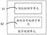
在一实施例中,所述数字处理单元4包括:In one embodiment, the
开关控制子单元,与所述模拟处理单元2的受控端电连接;a switch control subunit, electrically connected to the controlled end of the
阻抗检测子单元51,与所述模数转换单元3的信号输出端电连接,包括相互连接的测试信号滤波器和阻抗计算器;The
脑电信号处理子单元52,与所述模数转换单元3的信号输出端电连接,包括相互连接的脑电信号滤波器和脑电信号处理器。The EEG
本实施例中,数字处理单元4中分别包括开关控制子单元、阻抗检测子单元51和脑电信号处理子单元52。其中,开关控制子单元的控制端与模拟处理单元2的受控端电连接,用于控制模拟处理单元2中各开关的开启与闭合;阻抗检测子单元51的信号输入端与模数转换单元3的信号输出端电连接,用于接收模数转换单元3输出的阻抗测试信号,并通过测试信号滤波器过滤掉脑电信号,然后通过阻抗计算器计算出各个导联电极的理论接触阻抗。In this embodiment, the
脑电信号处理子单元52与模数转换单元3的信号输出端电连接,用于接收模数转换单元3输出的脑电信号,并通过脑电信号滤波器过滤掉阻抗测试信号,然后通过脑电信号处理器对脑电信号进行最终处理。The EEG
在一实施例中,所述模拟处理单元2包括滤波放大电路31和驱动电路32,所述滤波放大电路31的信号输入端与所述阻抗网络1的信号输入端连接,所述滤波放大电路31的信号输出端与所述模数转换单元3的信号输入端连接,所述驱动电路32的驱动端与所述阻抗网络1的受驱动端连接。In one embodiment, the
本实施例中,模拟处理单元2中包括滤波放大电路31和驱动电路32,滤波放大电路31的信号输入端与阻抗网络1的信号输出端连接,滤波放大电路31的信号输出端与模数转换单元3的信号输入端连接,用于对阻抗测试信号和脑电信号进行滤波和放大。驱动电路32的驱动端与阻抗网络1的受驱动端相连,无论是脑电采集模式还是阻抗测试模式,驱动电路32都能够提取脑电信号中的慢速变化波,并将慢速变化波经过阻抗模块到达用户的头皮,负反馈作用于头皮,抵消头皮上的静态电压波动,从而压缩脑电信号的动态范围使之与模拟处理单元2的信号输入范围相匹配,从而保持脑电信号的可跟踪性。In this embodiment, the
在一实施例中,所述阻抗网络1包括至少两个脑电信号测试电极Z1--Zn,阻抗测试辅助电极Zref和驱动辅助电极Zgnd,所述脑电信号测试电极Z1--Zn分别与所述滤波放大电路31的信号输入端连接,所述阻抗测试辅助电极Zref与所述滤波放大电路31的信号输入端连接,所述驱动辅助电极Zgnd与所述驱动电路32的驱动端连接。In one embodiment, the impedance network 1 includes at least two EEG signal test electrodes Z1--Zn, an impedance test auxiliary electrode Zref and a driving auxiliary electrode Zgnd, and the EEG signal test electrodes Z1--Zn are respectively connected with the EEG signal test electrodes Z1--Zn. The signal input terminal of the filter amplifying circuit 31 is connected, the impedance test auxiliary electrode Zref is connected to the signal input terminal of the filter amplifying circuit 31 , and the driving auxiliary electrode Zgnd is connected to the driving terminal of the driving circuit 32 .
本实施例中,阻抗网络1中包括至少两个脑电信号测试电极Z1--Zn、至少一个阻抗测试辅助电极Zref和至少一个驱动辅助电极Zgnd。脑电信号测试电极Z1--Zn分别与滤波放大电路31的信号输入端连接,阻抗测试辅助电极Zref与滤波放大电路31的信号输入端连接,驱动辅助电极Zgnd与驱动电路32的驱动端连接。其中,脑电信号测试电极Z1--Zn用于采集脑电信号,阻抗测试辅助电极Zref用于进行阻抗测试,驱动辅助电极Zgnd用于辅助驱动电路32保持脑电信号的可跟踪性。In this embodiment, the impedance network 1 includes at least two EEG signal testing electrodes Z1--Zn, at least one impedance testing auxiliary electrode Zref and at least one driving auxiliary electrode Zgnd. The EEG signal test electrodes Z1--Zn are respectively connected to the signal input end of the filter and amplifier circuit 31, the impedance test auxiliary electrode Zref is connected to the signal input end of the filter amplifier circuit 31, and the driving auxiliary electrode Zgnd is connected to the drive end of the drive circuit 32. The EEG signal test electrodes Z1--Zn are used for collecting EEG signals, the impedance test auxiliary electrode Zref is used for impedance test, and the driving auxiliary electrode Zgnd is used for the auxiliary drive circuit 32 to maintain the traceability of the EEG signal.
在一实施例中,所述信号正电源I1—In与所述脑电信号测试电极Z1--Zn一一对应,所述正电源I1—In的一端与所述脑电信号测试电极Z1--Zn的信号输出端、所述滤波放大电路31的信号输入端的节点连接。In one embodiment, the signal positive power source I1-In corresponds to the EEG signal test electrode Z1--Zn one-to-one, and one end of the positive power source I1-In corresponds to the EEG signal test electrode Z1-- The nodes of the signal output end of Zn and the signal input end of the filter and amplifying circuit 31 are connected.
本发明还提出一种脑电检测装置的阻抗检测方法,所述脑电检测装置的阻抗检测方法的步骤包括:The present invention also provides an impedance detection method for an EEG detection device, wherein the steps of the impedance detection method for the EEG detection device include:
步骤S100,获取控制指令,根据所述控制指令选择所述脑电检测装置的工作模式;Step S100, obtaining a control instruction, and selecting a working mode of the EEG detection device according to the control instruction;
步骤S200,若选择脑电采集模式,则采集脑电信号,并根据所述脑电信号生成脑电信号处理结果,并获取电源测试信号,根据所述电源测试信号生成阻抗检测信号,并基于所述阻抗检测信号获取理论接触阻抗。Step S200, if the EEG acquisition mode is selected, the EEG signal is collected, an EEG signal processing result is generated according to the EEG signal, a power supply test signal is obtained, an impedance detection signal is generated according to the power supply test signal, and an impedance detection signal is generated based on the EEG signal. The impedance detection signal is used to obtain the theoretical contact impedance.
本申请中,在脑电采集模式下,阻抗网络1中的至少两个脑电信号测试电极Z1--Zn放置在用户的头皮上,并分别采集人的头皮上的脑电信号,并且脑电信号可以同时到达模拟处理单元和辅助电路单元5,而在脑电采集模式下,模拟处理单元中的所有开关均断开,因此电源模块6不会对脑电采集产生影响,而辅助电路单元5对脑电信号中的有害大信号进行限制,然后脑电信号进入模拟处理单元2,模拟处理单元2将脑电信号进行滤波和放大,放大后的脑电信号进入模数转换单元3由模拟信号转换为数字信号,转换之后的脑电信号进入数字处理单元4,得到脑电信号处理结果。其中,脑电信号处理结果可以为曲线图模式的脑电图,也可以为文字模式的记录。In the present application, in the EEG acquisition mode, at least two EEG signal test electrodes Z1--Zn in the impedance network 1 are placed on the scalp of the user, and respectively collect the EEG signals on the scalp of the person, and the EEG The signal can reach the analog processing unit and the
在一实施例中,所述基于所述阻抗检测信号获取理论接触阻抗的步骤包括:In an embodiment, the step of obtaining the theoretical contact impedance based on the impedance detection signal includes:
获取正电源I1—In的电流波幅和电路放大增益;Obtain the current amplitude and circuit amplification gain of the positive power supply I1-In;
根据所述电流波幅、所述电路放大增益和所述阻抗检测信号计算理论接触阻抗。The theoretical contact impedance is calculated according to the current amplitude, the circuit amplification gain and the impedance detection signal.
本实施例中,以图6为例,由于正电源I1—In和负电源I0均为恒流源,那么就可以设恒流源的电流波幅为I,那么数字处理单元4中接收到的阻抗检测信号的波幅可以为U1,U2......Un-1,Un。In this embodiment, taking FIG. 6 as an example, since the positive power supply I1-In and the negative power supply I0 are both constant current sources, the current amplitude of the constant current source can be set as I, then the impedance received in the
那么就可以列出以下方程组:Then the following system of equations can be listed:

其中,Z1,Z2,Z3.......Zn,Zref,Zgnd分别为各导联电极对应的理论接触阻抗,Z1,Z2,Z3.......Zn为脑电信号测试电极Z1--Zn的理论接触阻抗,Zref为阻抗测试辅助电极Zref的理论接触阻抗,Zgnd为驱动辅助电极Zgnd的理论接触阻抗。而Z1r、Z2r......Znr分别为各脑电信号测试电极Z1--Zn对应的复合阻抗。Among them, Z1 , Z2 , Z3 ...... Zn , Zref , Zgnd are the theoretical contact impedance corresponding to each lead electrode, Z1 , Z2 , Z3 .......Zn is the theoretical contact impedance of the EEG signal test electrode Z1--Zn, Zref is the theoretical contact impedance of the impedance test auxiliary electrode Zref, andZgnd is the theoretical contact impedance of the driving auxiliary electrodeZgnd . And Z1r , Z2r ..... Znr are the composite impedance corresponding to each EEG signal test electrode Z1--Zn respectively.
具体地:Z1r=Z1+Zref;Z2r=Z2+Zref.......Znr=Zn+Zref。Specifically: Z1r =Z1 +Zref ; Z2r =Z2 +Zref ...... Znr =Zn +Zref .
g为模拟处理单元2的电路放大增益。在I、g、U1、U2......Un-1、Un都为已知量的情况下,可以计算得到各脑电信号测试电极Z1--Zn的复合阻抗和理论接触阻抗。在得到各脑电信号测试电极Z1--Zn的复合阻抗之后,可将这些复合阻抗与预设状态阈值进行比较,如果所有复合阻抗均小于或等于预设状态阈值,那么就认为复合阻抗对应的所有脑电信号测试电极Z1--Zn和阻抗测试辅助电极Zref处于正常状态;如果部分复合阻抗小于或等于预设状态阈值,那么就认为复合阻抗对应的脑电信号测试电极Z1--Zn处于正常状态,以及阻抗测试辅助电极Zref处于正常状态,如果所有的负荷阻抗均大于预设状态阈值,则认为阻抗测试辅助电极Zref阻抗过高或脱落,或者所有脑电信号测试电极Z1--Zn阻抗过高或脱落。g is the circuit amplification gain of the
本发明还提出一种脑电检测装置的阻抗检测设备,脑电检测装置的阻抗检测设备包括存储器、处理器、以及存储在所述存储器上并可在所述处理器上运行的脑电检测装置的阻抗检测程序,所述脑电检测装置的阻抗检测程序用于执行本发明各个实施例所述的方法。The present invention also provides an impedance detection device for an EEG detection device. The impedance detection device for the EEG detection device includes a memory, a processor, and an EEG detection device stored on the memory and running on the processor. The impedance detection program of the EEG detection device is used to execute the methods described in the various embodiments of the present invention.
本发明还提出一种存储介质,其上存储有脑电检测装置的阻抗检测程序。所述存储介质包括计算机可读存储介质,所述计算机可读存储介质可以是图1的中的存储器,也可以是如ROM(Read-Only Memory,只读存储器)/RAM(Random Access Memory,随机存取存储器)、磁碟、光盘中的至少一种,所述存储介质包括若干指令用以使得一台具有处理器的物联网终端设备(可以是手机,计算机,服务器,物联网终端,或者网络设备等)执行本发明各个实施例所述的方法。The invention also provides a storage medium on which the impedance detection program of the EEG detection device is stored. The storage medium includes a computer-readable storage medium, and the computer-readable storage medium may be the memory in FIG. 1 , or may be a ROM (Read-Only Memory, read-only memory)/RAM (Random Access Memory, random access memory), magnetic disk, optical disk, the storage medium includes several instructions to make an IoT terminal device with a processor (which can be a mobile phone, a computer, a server, an IoT terminal, or a network equipment, etc.) to execute the methods described in the various embodiments of the present invention.
在本发明中,术语“第一”“第二”“第三”“第四”“第五”仅用于描述的目的,而不能理解为指示或暗示相对重要性,对于本领域的普通技术人员而言,可以根据具体情况理解上述术语在本发明中的具体含义。In the present invention, the terms "first", "second", "third", "fourth" and "fifth" are only used for the purpose of description, and should not be construed as indicating or implying relative importance to ordinary skills in the art Personnel can understand the specific meanings of the above terms in the present invention according to specific situations.
在本说明书的描述中,参考术语“一个实施例”、“一些实施例”、“示例”、“具体示例”、或“一些示例”等的描述意指结合该实施例或示例描述的具体特征、结构、材料或者特点包含于本发明的多个实施例或示例中。在本说明书中,对上述术语的示意性表述不必须针对的是相同的实施例或示例。而且,描述的具体特征、结构、材料或者特点可以在任一个或多个实施例或示例中以合适的方式结合。此外,在不相互矛盾的情况下,本领域的技术人员可以将本说明书中描述的不同实施例或示例以及不同实施例或示例的特征进行结合和组合。In the description of this specification, description with reference to the terms "one embodiment," "some embodiments," "example," "specific example," or "some examples", etc., mean specific features described in connection with the embodiment or example , structures, materials or features are included in various embodiments or examples of the invention. In this specification, schematic representations of the above terms are not necessarily directed to the same embodiment or example. Furthermore, the particular features, structures, materials or characteristics described may be combined in any suitable manner in any one or more embodiments or examples. Furthermore, those skilled in the art may combine and combine the different embodiments or examples described in this specification, as well as the features of the different embodiments or examples, without conflicting each other.
尽管上面已经示出和描述了本发明的实施例,本发明保护的范围并不局限于此,可以理解的是,上述实施例是示例性的,不能理解为对本发明的限制,本领域的普通技术人员在本发明的范围内可以对上述实施例进行变化、修改和替换,这些变化、修改和替换都应涵盖在本发明的保护范围之内。因此,本发明的保护范围应以权利要求的保护范围为准。Although the embodiments of the present invention have been shown and described above, the scope of protection of the present invention is not limited thereto. It should be understood that the above embodiments are exemplary and should not be construed as limitations of the present invention. Those skilled in the art can make changes, modifications and substitutions to the above embodiments within the scope of the present invention, and these changes, modifications and substitutions should all be covered within the protection scope of the present invention. Therefore, the protection scope of the present invention should be subject to the protection scope of the claims.
Claims (10)
Translated fromChinesePriority Applications (1)
| Application Number | Priority Date | Filing Date | Title |
|---|---|---|---|
| CN202210359138.5ACN114699089B (en) | 2022-04-07 | 2022-04-07 | Electroencephalogram detection device, impedance detection method, and storage medium |
Applications Claiming Priority (1)
| Application Number | Priority Date | Filing Date | Title |
|---|---|---|---|
| CN202210359138.5ACN114699089B (en) | 2022-04-07 | 2022-04-07 | Electroencephalogram detection device, impedance detection method, and storage medium |
Publications (2)
| Publication Number | Publication Date |
|---|---|
| CN114699089Atrue CN114699089A (en) | 2022-07-05 |
| CN114699089B CN114699089B (en) | 2025-07-29 |
Family
ID=82172161
Family Applications (1)
| Application Number | Title | Priority Date | Filing Date |
|---|---|---|---|
| CN202210359138.5AActiveCN114699089B (en) | 2022-04-07 | 2022-04-07 | Electroencephalogram detection device, impedance detection method, and storage medium |
Country Status (1)
| Country | Link |
|---|---|
| CN (1) | CN114699089B (en) |
Cited By (3)
| Publication number | Priority date | Publication date | Assignee | Title |
|---|---|---|---|---|
| CN114699091A (en)* | 2022-04-07 | 2022-07-05 | 深圳市德力凯医疗设备股份有限公司 | Electroencephalogram detection device, impedance detection method, and storage medium |
| CN114699090A (en)* | 2022-04-07 | 2022-07-05 | 深圳市德力凯医疗设备股份有限公司 | Electroencephalogram detection device, impedance detection method, and storage medium |
| CN114916941A (en)* | 2022-04-07 | 2022-08-19 | 深圳市德力凯医疗设备股份有限公司 | EEG detection device, impedance detection method and storage medium |
Citations (11)
| Publication number | Priority date | Publication date | Assignee | Title |
|---|---|---|---|---|
| CN1502300A (en)* | 2002-10-24 | 2004-06-09 | 三星电子株式会社 | Device and method for measuring local skin impedance using multiple array electrodes |
| KR100774100B1 (en)* | 2007-07-31 | 2007-11-06 | 전력품질기술주식회사 | Improved Hybrid Harmonic Filter |
| CN101199418A (en)* | 2006-12-12 | 2008-06-18 | 深圳迈瑞生物医疗电子股份有限公司 | Brain impedance detection circuitry and EEG checking device |
| CN102944736A (en)* | 2012-11-22 | 2013-02-27 | 江苏大为科技股份有限公司 | Circuit for detecting wide-range, high-precision and multichannel currents based on optical couplings |
| CN103023330A (en)* | 2012-12-18 | 2013-04-03 | 深圳市明微电子股份有限公司 | Switching power supply and self-adaption multi-mode control circuit |
| CN205083476U (en)* | 2015-11-03 | 2016-03-16 | 北京怡和嘉业医疗科技有限公司 | A contact impedance detection circuitry and electroencephalograph for electroencephalograph |
| RU2646311C1 (en)* | 2016-11-11 | 2018-03-02 | Общество с ограниченной ответственностью "Научно-Технический Центр Завод Балансировочных машин" | Signal transmission system from sensors with analogue output for the two-wireless communication line |
| CN212213728U (en)* | 2019-12-17 | 2020-12-25 | 电子科技大学 | Sleep monitoring and sleep regulation device based on human multimodal signals |
| CN113397552A (en)* | 2021-05-12 | 2021-09-17 | 肇庆美兰特科技有限公司 | Novel electroencephalogram signal acquisition method and system |
| CN113476741A (en)* | 2016-11-16 | 2021-10-08 | 西安交通大学 | Transcranial direct current stimulation device and working method |
| CN113672025A (en)* | 2021-08-12 | 2021-11-19 | 深圳市中科蓝讯科技股份有限公司 | Power supply circuit, chip and earphone |
- 2022
- 2022-04-07CNCN202210359138.5Apatent/CN114699089B/enactiveActive
Patent Citations (11)
| Publication number | Priority date | Publication date | Assignee | Title |
|---|---|---|---|---|
| CN1502300A (en)* | 2002-10-24 | 2004-06-09 | 三星电子株式会社 | Device and method for measuring local skin impedance using multiple array electrodes |
| CN101199418A (en)* | 2006-12-12 | 2008-06-18 | 深圳迈瑞生物医疗电子股份有限公司 | Brain impedance detection circuitry and EEG checking device |
| KR100774100B1 (en)* | 2007-07-31 | 2007-11-06 | 전력품질기술주식회사 | Improved Hybrid Harmonic Filter |
| CN102944736A (en)* | 2012-11-22 | 2013-02-27 | 江苏大为科技股份有限公司 | Circuit for detecting wide-range, high-precision and multichannel currents based on optical couplings |
| CN103023330A (en)* | 2012-12-18 | 2013-04-03 | 深圳市明微电子股份有限公司 | Switching power supply and self-adaption multi-mode control circuit |
| CN205083476U (en)* | 2015-11-03 | 2016-03-16 | 北京怡和嘉业医疗科技有限公司 | A contact impedance detection circuitry and electroencephalograph for electroencephalograph |
| RU2646311C1 (en)* | 2016-11-11 | 2018-03-02 | Общество с ограниченной ответственностью "Научно-Технический Центр Завод Балансировочных машин" | Signal transmission system from sensors with analogue output for the two-wireless communication line |
| CN113476741A (en)* | 2016-11-16 | 2021-10-08 | 西安交通大学 | Transcranial direct current stimulation device and working method |
| CN212213728U (en)* | 2019-12-17 | 2020-12-25 | 电子科技大学 | Sleep monitoring and sleep regulation device based on human multimodal signals |
| CN113397552A (en)* | 2021-05-12 | 2021-09-17 | 肇庆美兰特科技有限公司 | Novel electroencephalogram signal acquisition method and system |
| CN113672025A (en)* | 2021-08-12 | 2021-11-19 | 深圳市中科蓝讯科技股份有限公司 | Power supply circuit, chip and earphone |
Cited By (5)
| Publication number | Priority date | Publication date | Assignee | Title |
|---|---|---|---|---|
| CN114699091A (en)* | 2022-04-07 | 2022-07-05 | 深圳市德力凯医疗设备股份有限公司 | Electroencephalogram detection device, impedance detection method, and storage medium |
| CN114699090A (en)* | 2022-04-07 | 2022-07-05 | 深圳市德力凯医疗设备股份有限公司 | Electroencephalogram detection device, impedance detection method, and storage medium |
| CN114916941A (en)* | 2022-04-07 | 2022-08-19 | 深圳市德力凯医疗设备股份有限公司 | EEG detection device, impedance detection method and storage medium |
| CN114699090B (en)* | 2022-04-07 | 2025-07-29 | 深圳德力凯医疗电子股份有限公司 | Electroencephalogram detection device, impedance detection method, and storage medium |
| CN114916941B (en)* | 2022-04-07 | 2025-07-29 | 深圳德力凯医疗电子股份有限公司 | Electroencephalogram detection device, impedance detection method, and storage medium |
Also Published As
| Publication number | Publication date |
|---|---|
| CN114699089B (en) | 2025-07-29 |
Similar Documents
| Publication | Publication Date | Title |
|---|---|---|
| JP5450436B2 (en) | Non-contact type biopotential sensor | |
| CN114699089A (en) | Electroencephalogram detection device, impedance detection method, and storage medium | |
| CN114916941A (en) | EEG detection device, impedance detection method and storage medium | |
| US8442628B2 (en) | Differential voltage sensing method | |
| EP2298164A2 (en) | Cardiac monitoring circuit with adaptive sampling | |
| US9622672B2 (en) | Digitally invertible universal amplifier for recording and processing of bioelectric signals | |
| CN110840454B (en) | Electroencephalogram signal acquisition device and method | |
| KR101832734B1 (en) | Improved bio-potential measurement system | |
| CN114699091A (en) | Electroencephalogram detection device, impedance detection method, and storage medium | |
| CN114699090A (en) | Electroencephalogram detection device, impedance detection method, and storage medium | |
| Su et al. | Wireless ECG detection system with low-power analog front-end circuit and bio-processing ZigBee firmware | |
| CN204468044U (en) | A kind of heart sound signal acquisition system | |
| CN113384276A (en) | EEG signal channel acquisition circuit | |
| EP4091548A1 (en) | Signal measurement method and device | |
| Szakacs-Simon et al. | Signal conditioning techniques for health monitoring devices | |
| CN215739008U (en) | EEG signal channel acquisition circuit | |
| CN116919416A (en) | Correction circuit, detection circuit and detection method for lead falling detection | |
| CN110897632A (en) | Full-wireless distributed human physiological signal acquisition active electrode system | |
| RU2102004C1 (en) | Device for reading, recording and analyzing electrophysiological signals and unit for protecting against emergency power supply currents | |
| Xu et al. | Low-cost circuit design for eeg signal amplification and extraction | |
| KR101211065B1 (en) | Wireless Control System Using Brain Computer Interface | |
| Chinna Babu et al. | A Review on OTA with Low Power and Low Noise Techniques for Medical Applications | |
| KR101772202B1 (en) | Monitoring device and method for attachment status of biopotential electrodes | |
| KR101832733B1 (en) | Bio-potential measurement system | |
| Saini | A Review on Low Voltage Low Power Operational Transconductance Amplifier (OTA) for Biomedical Application |
Legal Events
| Date | Code | Title | Description |
|---|---|---|---|
| PB01 | Publication | ||
| PB01 | Publication | ||
| SE01 | Entry into force of request for substantive examination | ||
| SE01 | Entry into force of request for substantive examination | ||
| CB02 | Change of applicant information | ||
| CB02 | Change of applicant information | Country or region after:China Address after:518000, 18th Floor, Building B, High tech Innovation Center, Guangqiao Road, Tianliao Community, Yutang Street, Guangming District, Shenzhen, Guangdong Province Applicant after:Shenzhen Delikai Medical Electronics Co.,Ltd. Address before:518107 18th floor, block B, high tech innovation center, guangqiao Road, Tian'an community, Yutang street, Guangming District, Shenzhen, Guangdong Applicant before:SHENZHEN DELICA MEDICAL EQUIPMENT Co.,Ltd. Country or region before:China | |
| GR01 | Patent grant | ||
| GR01 | Patent grant |