CN114690414A - Waveguide-based augmented reality device and method therefor - Google Patents
Waveguide-based augmented reality device and method thereforDownload PDFInfo
- Publication number
- CN114690414A CN114690414ACN202011607192.4ACN202011607192ACN114690414ACN 114690414 ACN114690414 ACN 114690414ACN 202011607192 ACN202011607192 ACN 202011607192ACN 114690414 ACN114690414 ACN 114690414A
- Authority
- CN
- China
- Prior art keywords
- image light
- assembly
- waveguide
- polarized image
- light
- Prior art date
- Legal status (The legal status is an assumption and is not a legal conclusion. Google has not performed a legal analysis and makes no representation as to the accuracy of the status listed.)
- Granted
Links
Images


Classifications
- G—PHYSICS
- G02—OPTICS
- G02B—OPTICAL ELEMENTS, SYSTEMS OR APPARATUS
- G02B27/00—Optical systems or apparatus not provided for by any of the groups G02B1/00 - G02B26/00, G02B30/00
- G02B27/01—Head-up displays
- G02B27/017—Head mounted
- G02B27/0172—Head mounted characterised by optical features
- G—PHYSICS
- G02—OPTICS
- G02B—OPTICAL ELEMENTS, SYSTEMS OR APPARATUS
- G02B27/00—Optical systems or apparatus not provided for by any of the groups G02B1/00 - G02B26/00, G02B30/00
- G02B27/01—Head-up displays
- G—PHYSICS
- G02—OPTICS
- G02B—OPTICAL ELEMENTS, SYSTEMS OR APPARATUS
- G02B27/00—Optical systems or apparatus not provided for by any of the groups G02B1/00 - G02B26/00, G02B30/00
- G02B27/28—Optical systems or apparatus not provided for by any of the groups G02B1/00 - G02B26/00, G02B30/00 for polarising
Landscapes
- Physics & Mathematics (AREA)
- General Physics & Mathematics (AREA)
- Optics & Photonics (AREA)
Abstract
Description
Translated fromChinese技术领域technical field
本发明涉及增强现实技术领域,特别是涉及一种基于波导的增强现实装置及其方法。The present invention relates to the technical field of augmented reality, in particular to a waveguide-based augmented reality device and a method thereof.
背景技术Background technique
近年来,微型显示芯片技术的出现,使得小型化和高分辨率的投影显示成为可能。随着投影显示技术的不断发展以及市场需求,可穿戴的微投影系统越来越受到重视,尤其是在现如今发展火热的增强现实(Augmented reality,AR)等领域。增强现实又称扩增现实或混合现实,是一种将虚拟物体叠加到真实环境并进行互动的技术,通过将虚拟物体的图像以及真实环境的图像透射到用户眼中,使用户获得虚拟与现实融合的体验。In recent years, the emergence of microdisplay chip technology has made miniaturized and high-resolution projection display possible. With the continuous development of projection display technology and market demand, wearable micro-projection systems have received more and more attention, especially in the field of augmented reality (AR), which is currently developing hotly. Augmented reality, also known as augmented reality or mixed reality, is a technology that superimposes virtual objects on the real environment and interacts with it. experience.
目前,虽然市场上存在多种AR光学系统方案,但真正能够面向消费者的产品仍然存在很多不足,比如,亮度低、视场角小、尺寸大、成本高、设备笨重等。特别是随着自发光显示芯片作为图像显示源的折反式光学系统出现,因其在控制成本、减小体积以及降低难度上具有一定优势而备受青睐。如图1所示,现有的折反式增强现实设备10P通常包括图像源组件11P、透镜12P、半反半透镜13P以及曲面反射镜14P,通过该图像源组件11P发射的图像光线,在经由该透镜12P聚焦后,再经由该半反半透镜13P和该曲面反射镜14P反射至人眼中以呈现放大的虚像,而人眼能够透过该半反半透镜13P和该曲面反射镜14P看到真实物体,使得虚拟图像与真实世界叠加即可完成增强交互。At present, although there are a variety of AR optical system solutions on the market, there are still many deficiencies in the products that can be truly consumer-oriented, such as low brightness, small field of view, large size, high cost, and bulky equipment. Especially with the emergence of catadioptric optical systems with self-luminous display chips as image display sources, they are favored because of their advantages in cost control, volume reduction, and difficulty reduction. As shown in FIG. 1 , an existing catadioptric augmented
然而,现有的折反式增强现实设备10P虽然能够通过折返图像光而增加光程,但会因采用的半反半透镜13P和曲面反射镜14P均为曲面元件而导致设备前端的整体尺寸却比较大;与此同时,图像源组件11P和透镜12P均位于设备的前端,造成设备前端的重量也比较重。However, although the existing catadioptric augmented
而随着波导技术的发展,波导技术也逐渐被广泛应用到增强现实领域,以替代现有的折返式增强现实设备10P中的半反半透镜13P和曲面反射镜14P。例如,如图2所示,现有的基于波导的增强现实设备20P通常包括图像源组件21P、透镜组件22P以及波导23P,这样通过该图像源组件21P发射的图像光线,在经由该透镜组件22P聚焦后,再经由该波导23P传导至人眼中以呈现放大的虚像,而人眼能够透过该波导23P看到真实物体,使得虚拟图像与真实世界叠加即可完成增强交互。With the development of the waveguide technology, the waveguide technology has gradually been widely used in the field of augmented reality to replace the
然而,该现有的基于波导的增强现实设备20P虽然能够解决设备前端尺寸较大、重量较重的问题,但因为该现有的基于波导的增强现实设备20P失去了折返光路而不得不增大该透镜组件22P中的透镜数量来延长光程,以确保图像光线具有足够的光程而形成质量较高的虚拟图像,这样该透镜组件22P的体积和重量将急剧变大,导致该现有的基于波导的增强现实设备20P的整体尺寸和重量也将变大,更难以接受的是该现有的基于波导的增强现实设备20P的大部分重量将集中到该透镜组件22P以造成重量分布不均匀,进而影响用户的佩戴舒适度。However, although the existing waveguide-based augmented
发明内容SUMMARY OF THE INVENTION
本发明的一优势在于提供一基于波导的增强现实装置及其方法,其能够在保证图像光具有足够的光程的同时,减小装置的尺寸和重量,有助于改善用户的佩戴舒适度。An advantage of the present invention is to provide a waveguide-based augmented reality device and a method thereof, which can reduce the size and weight of the device while ensuring that the image light has a sufficient optical path, and help improve the wearing comfort of the user.
本发明的另一优势在于提供一基于波导的增强现实装置及其方法,其中,在本发明的一实施例中,所述基于波导的增强现实装置能够采用平面折叠技术在较小的物理空间内增加图像光的光程,有助于提高装置结构的紧凑性,降低装置的尺寸和重量。Another advantage of the present invention is to provide a waveguide-based augmented reality device and a method thereof, wherein, in an embodiment of the present invention, the waveguide-based augmented reality device can use a planar folding technique in a smaller physical space Increasing the optical path of the image light helps to improve the compactness of the device structure and reduce the size and weight of the device.
本发明的另一优势在于提供一基于波导的增强现实装置及其方法,其中,在本发明的一实施例中,所述基于波导的增强现实装置能够在波导的边缘对平面折叠光组件进行封装,以在简化封装工艺、提高封装质量的同时,避免对波导的耦入区域和耦出区域产生干扰。Another advantage of the present invention is to provide a waveguide-based augmented reality device and a method thereof, wherein, in an embodiment of the present invention, the waveguide-based augmented reality device can encapsulate the planar folded optical component at the edge of the waveguide , so as to simplify the packaging process and improve the packaging quality, while avoiding interference to the coupling-in area and the coupling-out area of the waveguide.
本发明的另一优势在于提供一基于波导的增强现实装置及其方法,其中,在本发明的一实施例中,所述基于波导的增强现实装置能够整体地封装所述平面折叠光组件和所述波导,以便降低所述平面折叠光组件的投影区域与所述波导的耦入区域的对准难度。Another advantage of the present invention is to provide a waveguide-based augmented reality device and a method thereof, wherein, in an embodiment of the present invention, the waveguide-based augmented reality device can integrally encapsulate the planar folded optical component and all the The waveguide is used to reduce the difficulty of aligning the projection area of the planar folded light assembly with the coupling-in area of the waveguide.
本发明的另一优势在于提供一基于波导的增强现实装置及其方法,其中,在本发明的一实施例中,所述基于波导的增强现实装置能够利用所述平面折叠光组件的显影区域对光线进行会聚或发散,以替代曲面的远视或近视镜片,有助于使远视或近视用户直接使用所述基于波导的增强现实装置就能够看到清晰的虚拟图像和真实物体,从而获得良好的增强现实体验。Another advantage of the present invention is to provide a waveguide-based augmented reality device and method thereof, wherein, in an embodiment of the present invention, the waveguide-based augmented reality device can utilize the developing area pair of the planar folded optical component Convergence or divergence of light to replace curved lenses for hyperopia or myopia, helping to enable hyperopia or myopia users to see clear virtual images and real objects directly using the waveguide-based augmented reality device for good enhancement real experience.
本发明的另一优势在于提供一基于波导的增强现实装置及其方法,其中为了达到上述目的,在本发明中不需要采用昂贵的材料或复杂的结构。因此,本发明成功和有效地提供一解决方案,不只提供一基于波导的增强现实装置及其方法,同时还增加了所述基于波导的增强现实装置及其方法的实用性和可靠性。Another advantage of the present invention is to provide a waveguide-based augmented reality device and method thereof, wherein in order to achieve the above-mentioned objects, the present invention does not need to use expensive materials or complicated structures. Therefore, the present invention successfully and effectively provides a solution that not only provides a waveguide-based augmented reality device and method, but also increases the practicability and reliability of the waveguide-based augmented reality device and method.
为了实现上述至少一优势或其他优势和目的,本发明提供了一基于波导的增强现实装置,包括:In order to achieve at least one of the above advantages or other advantages and objectives, the present invention provides a waveguide-based augmented reality device, including:
一图像源组件,用于发射图像光;an image source component for emitting image light;
一波导组件,其中所述波导组件具有并排布置的耦入区域和耦出区域,并且所述波导组件的所述耦入区域对应于所述图像源组件;以及a waveguide assembly, wherein the waveguide assembly has an in-coupling region and an out-coupling region arranged side-by-side, and the coupling-in region of the waveguide assembly corresponds to the image source assembly; and
一平面折叠光组件,其中所述平面折叠光组件被设置于所述图像源组件和所述波导组件之间的光路中,其中所述平面折叠光组件具有光焦度,并且所述平面折叠光组件包括相互叠置的多个平面光学元件,以通过所述多个平面光学元件可选择偏转角度地折叠所述图像源组件和所述波导组件之间的光路,用于使来自所述图像源组件的该图像光在所述平面折叠光组件内被多次折返的同时被会聚或发散之后,先从所述波导组件的所述耦入区域耦入,再从所述波导组件的所述耦出区域耦出。A plane folded light assembly, wherein the plane folded light assembly is disposed in the optical path between the image source assembly and the waveguide assembly, wherein the plane folded light assembly has optical power, and the plane folded light assembly The assembly includes a plurality of planar optical elements stacked on top of each other to selectively fold an optical path between the image source assembly and the waveguide assembly by the plurality of planar optical elements for allowing the image source from the image source After the image light of the component is condensed or diverged while being folded multiple times in the planar folded optical component, it is first coupled in from the coupling region of the waveguide component, and then from the coupling area of the waveguide component. out-coupling.
根据本申请的一实施例,所述平面折叠光组件中的所述多个平面光学元件包括具有光焦度的一第二光学元件、一第三光学元件以及一第四光学元件,其中所述第二光学元件用于透射第一偏振图像光,且可选择角度地反射第二偏振图像光;其中所述第三光学元件用于将该第一偏振图像光和该第二偏振图像光与第三偏振图像光和第四偏振图像光相互转换;其中所述第四光学元件用于反射该第三偏振图像光,且透射该第四偏振图像光;其中该第一偏振图像光与该第二偏振图像光相互正交地偏振,并且该第三偏振图像光与该第四偏振图像光相互正交地偏振。According to an embodiment of the present application, the plurality of planar optical elements in the planar folded light assembly include a second optical element, a third optical element and a fourth optical element having optical power, wherein the The second optical element is used for transmitting the first polarized image light and selectively reflecting the second polarized image light; wherein the third optical element is used for combining the first polarized image light and the second polarized image light with the first polarized image light and the second polarized image light. The three-polarized image light and the fourth-polarized image light are mutually converted; wherein the fourth optical element is used to reflect the third-polarized image light and transmit the fourth-polarized image light; wherein the first polarized image light and the second polarized image light The polarized image light is polarized orthogonally to each other, and the third polarized image light and the fourth polarized image light are polarized orthogonally to each other.
根据本申请的一实施例,所述平面折叠光组件中的所述多个平面光学元件进一步包括一第一光学元件,其中所述第一光学元件用于将来自所述图像源组件的该图像光起偏为该第一偏振图像光,并且所述第一光学元件、所述第二光学元件、所述第三光学元件以及所述第四光学元件依次被叠置于所述图像源组件和所述波导组件之间的光路。According to an embodiment of the present application, the plurality of planar optical elements in the planar folded light assembly further includes a first optical element, wherein the first optical element is used to convert the image from the image source assembly The light is polarized to the first polarized image light, and the first optical element, the second optical element, the third optical element and the fourth optical element are sequentially stacked on the image source assembly and the optical paths between the waveguide assemblies.
根据本申请的一实施例,所述第一光学元件为一圆偏振件,其中所述圆偏振件用于将该图像光起偏为圆偏振光。According to an embodiment of the present application, the first optical element is a circular polarizer, wherein the circular polarizer is used to polarize the image light into circularly polarized light.
根据本申请的一实施例,所述平面折叠光组件中的所述多个平面光学元件进一步包括一第一光学元件,其中所述第一光学元件用于将来自所述图像源组件的该图像光起偏为该第四偏振图像光,并且所述第一光学元件、所述第四光学元件、所述第三光学元件以及所述第二光学元件依次被叠置于所述图像源组件和所述波导组件之间的光路。According to an embodiment of the present application, the plurality of planar optical elements in the planar folded light assembly further includes a first optical element, wherein the first optical element is used to convert the image from the image source assembly The light is polarized to the fourth polarized image light, and the first optical element, the fourth optical element, the third optical element, and the second optical element are sequentially stacked on the image source assembly and the optical paths between the waveguide assemblies.
根据本申请的一实施例,所述第一光学元件为一线偏振件,其中所述线偏振件用于将该图像光起偏为线偏振光。According to an embodiment of the present application, the first optical element is a linear polarizer, wherein the linear polarizer is used to polarize the image light into linear polarized light.
根据本申请的一实施例,所述第二光学元件为一偏振体全息件,用于透射左旋圆偏振图像光和右旋圆偏振图像光中的一种,并可选择角度地反射该左旋圆偏振图像光和该右旋圆偏振图像光中的另一种;其中所述第三光学元件为一1/4波片;其中所述第四光学元件为一偏振反射件,用于透射P偏振图像光和S偏振图像光中的一种,并反射该P偏振图像光和该S偏振图像光中的另一种。According to an embodiment of the present application, the second optical element is a polarized body hologram, used to transmit one of left-handed circularly polarized image light and right-handed circularly polarized image light, and can selectively reflect the left-handed circularly polarized image light at an angle Another one of the polarized image light and the right-handed circularly polarized image light; wherein the third optical element is a 1/4 wave plate; wherein the fourth optical element is a polarized reflector for transmitting P polarization One of the image light and the S-polarized image light, and the other of the P-polarized image light and the S-polarized image light is reflected.
根据本申请的一实施例,所述第二光学元件与所述第三光学元件被间隔地叠置,以在所述第二光学元件和所述第三光学元件之间形成一透光间隙。According to an embodiment of the present application, the second optical element and the third optical element are stacked at intervals to form a light transmission gap between the second optical element and the third optical element.
根据本申请的一实施例,所述平面折叠光组件中的所述多个平面光学元件进一步包括一平面透光元件,其中所述平面透光元件被设置于所述透光间隙,并且所述平面透光元件的折射率大于空气的折射率。According to an embodiment of the present application, the plurality of planar optical elements in the planar folded light assembly further include a planar light-transmitting element, wherein the planar light-transmitting element is disposed in the light-transmitting gap, and the The refractive index of the planar light-transmitting element is greater than that of air.
根据本申请的一实施例,所述平面折叠光组件与所述波导组件的所述耦入区域相匹配地设置。According to an embodiment of the present application, the planar folded optical component is arranged to match the coupling-in area of the waveguide component.
根据本申请的一实施例,所述平面折叠光组件同时与所述波导组件的所述耦入区域和所述耦出区域相匹配地设置。According to an embodiment of the present application, the planar folded optical component is arranged to match the coupling-in region and the coupling-out region of the waveguide assembly at the same time.
根据本申请的一实施例,所述平面折叠光组件同时与所述波导组件的所述耦入区域和所述耦出区域相匹配地设置,并且所述平面折叠光组件中的所述第一光学元件仅与所述波导组件的所述耦入区域相匹配地对应。According to an embodiment of the present application, the planar folded optical assembly is configured to match the coupling-in region and the coupling-out region of the waveguide assembly at the same time, and the first in the planar folded optical assembly Optical elements correspond only to the coupling-in regions of the waveguide assembly.
根据本申请的一实施例,所述平面折叠光组件中的所述第二光学元件具有并排布置的第一光学区域和第二光学区域,其中所述第二光学元件的所述第一光学区域对应于所述波导组件的所述耦入区域,用于透射该第一偏振图像光,且可选择角度地反射该第二偏振图像光;其中所述第二光学元件的所述第二光学区域对应于所述波导组件的所述耦出区域,用于透射该第二偏振图像光,且可选择角度地反射该第一偏振图像光。According to an embodiment of the present application, the second optical element in the planar folded light assembly has a first optical zone and a second optical zone arranged side by side, wherein the first optical zone of the second optical element the coupling-in area corresponding to the waveguide assembly for transmitting the first polarized image light and selectively reflecting the second polarized image light; wherein the second optical area of the second optical element The coupling-out area corresponding to the waveguide component is used for transmitting the second polarized image light and selectively reflecting the first polarized image light.
根据本申请的一实施例,所述第二光学元件包括偏振敏感方向相反的第一偏振体全息件和第二偏振体全息件,其中所述第一偏振体全息件和所述第二偏振体全息件被并排地设置以分别提供所述第一光学区域和所述第二光学区域。According to an embodiment of the present application, the second optical element comprises a first polarizer hologram and a second polarizer hologram with opposite polarization sensitive directions, wherein the first polarizer hologram and the second polarizer The holograms are arranged side by side to provide the first optical zone and the second optical zone, respectively.
根据本申请的一实施例,所述波导组件为SRG衍射波导或二维阵列波导。According to an embodiment of the present application, the waveguide component is an SRG diffractive waveguide or a two-dimensional array waveguide.
根据本申请的另一方面,本申请进一步提供了基于波导的增强现实装置的制造方法,包括步骤:According to another aspect of the present application, the present application further provides a method for manufacturing a waveguide-based augmented reality device, comprising the steps of:
对应地设置用于发射图像光的一图像源组件于一波导组件的耦入区域;和correspondingly disposing an image source assembly for emitting image light in the coupling-in region of a waveguide assembly; and
设置具有光焦度的一平面折叠光组件于该图像源组件和该波导组件之间的光路中,其中所述平面折叠光组件包括相互叠置的多个平面光学元件,以通过所述多个平面光学元件可选择偏转角度地折叠所述图像源组件和所述波导组件之间的光路,用于使来自所述图像源组件的该图像光在所述平面折叠光组件内被多次折返的同时被会聚或发散之后,先从所述波导组件的所述耦入区域耦入,再从所述波导组件的所述耦出区域耦出。A plane folded light assembly with optical power is arranged in the optical path between the image source assembly and the waveguide assembly, wherein the plane folded light assembly includes a plurality of plane optical elements stacked on each other to pass the plurality of plane optical elements The flat optical element folds the light path between the image source assembly and the waveguide assembly with a selectable deflection angle, so that the image light from the image source assembly is refracted multiple times within the flat folded light assembly After being converged or diverged at the same time, it is first coupled in from the coupling-in region of the waveguide assembly, and then coupled out from the coupling-out region of the waveguide assembly.
根据本申请的另一方面,本申请进一步提供了近眼显示方法,包括步骤:According to another aspect of the present application, the present application further provides a near-eye display method, comprising the steps of:
发射一图像光;emit an image light;
可选择偏转角度地多次折返该图像光以会聚或发散该图像光;以及Returning the image light multiple times with selectable deflection angles to converge or diverge the image light; and
全反射地传导被会聚或发散后的该图像光至人眼以成像。The condensed or diverged image light is transmitted to the human eye for imaging in total reflection.
根据本申请的一实施例,所述可选择偏转角度地多次折返该图像光以会聚或发散该图像光的步骤,包括步骤:According to an embodiment of the present application, the step of returning the image light multiple times with a selectable deflection angle to converge or diverge the image light includes the steps of:
起偏该图像光以形成一第一偏振图像光;polarizing the image light to form a first polarized image light;
透射该第一偏振图像光以转换为一第三偏振图像光;transmitting the first polarized image light to be converted into a third polarized image light;
反射回该第三偏振图像光以转换为一第二偏振图像光,其中该第二偏振图像光与该第一偏振图像光相互正交地偏振;reflecting back the third polarized image light to be converted into a second polarized image light, wherein the second polarized image light and the first polarized image light are polarized orthogonally to each other;
可选择角度地反射回该第二偏振图像光以发散或会聚该第二偏振图像光;以及selectably angularly reflected back the second polarized image light to diverge or converge the second polarized image light; and
转换该第二偏振图像光以形成一第四偏振图像光,其中该第四偏振图像光与该第三偏振图像光相互正交地偏振。The second polarized image light is converted to form a fourth polarized image light, wherein the fourth polarized image light and the third polarized image light are polarized orthogonally to each other.
根据本申请的一实施例,所述可选择偏转角度地多次折返该图像光以会聚或发散该图像光的步骤,包括步骤:According to an embodiment of the present application, the step of returning the image light multiple times with a selectable deflection angle to converge or diverge the image light includes the steps of:
起偏该图像光以形成一第四偏振图像光;polarizing the image light to form a fourth polarized image light;
透射该第四偏振图像光以转换为一第二偏振图像光;transmitting the fourth polarized image light to be converted into a second polarized image light;
可选择角度地反射回该第二偏振图像光以发散或会聚该第二偏振图像光;selectably reflecting back the second polarized image light to diverge or converge the second polarized image light;
转换该第二偏振图像光以形成一第三偏振图像光,其中该第三偏振图像光与该第四偏振图像光相互正交地偏振;以及converting the second polarized image light to form a third polarized image light, wherein the third polarized image light and the fourth polarized image light are polarized orthogonally to each other; and
反射回该第三偏振图像光以转换为一第一偏振图像光,其中该第一偏振图像光与该第二偏振图像光相互正交地偏振。The third polarized image light is reflected back to be converted into a first polarized image light, wherein the first polarized image light and the second polarized image light are polarized orthogonally to each other.
根据本申请的一实施例,所述全反射地传导被会聚或发散后的该图像光至人眼以成像的步骤,包括步骤:According to an embodiment of the present application, the step of totally reflecting the condensed or divergent image light to the human eye for imaging includes the steps of:
耦入该第四偏振图像光;coupled into the fourth polarized image light;
全反射地传导被耦入的该第四偏振图像光;以及Conducting the coupled-in fourth polarized image light in total reflection; and
耦出被全反射地传导的该第四偏振图像光。The fourth polarized image light that is conducted in total reflection is coupled out.
根据本申请的一实施例,所述全反射地传导被会聚或发散后的该图像光至人眼以成像的步骤,进一步包括步骤:According to an embodiment of the present application, the step of totally reflecting the condensed or divergent image light to the human eye for imaging further includes the steps of:
透射被耦出的该第四偏振图像光以转换为该第一偏振图像光;transmitting the coupled out fourth polarized image light to be converted into the first polarized image light;
可选择角度地反射回该第一偏振图像光以发散或会聚该第一偏振图像光;selectably reflecting back the first polarized image light to diverge or converge the first polarized image light;
转换该第一偏振图像光以形成该第三偏振图像光;以及converting the first polarized image light to form the third polarized image light; and
反射回该第三偏振图像光以转换为该第二偏振图像光而传播至人眼成像。The third polarized image light is reflected back to be converted into the second polarized image light and propagated to the human eye for imaging.
通过对随后的描述和附图的理解,本发明进一步的目的和优势将得以充分体现。Further objects and advantages of the present invention will be fully realized by an understanding of the ensuing description and drawings.
本发明的这些和其它目的、特点和优势,通过下述的详细说明,附图和权利要求得以充分体现。These and other objects, features and advantages of the present invention are fully embodied by the following detailed description, drawings and claims.
附图说明Description of drawings
图1示出了现有的折反式增强现实设备的结构示意图。FIG. 1 shows a schematic structural diagram of a conventional folding and transversal augmented reality device.
图2示出了现有的基于波导的增强现实设备的结构示意图。FIG. 2 shows a schematic structural diagram of an existing waveguide-based augmented reality device.
图3是根据本发明的一第一实施例的基于波导的增强现实装置的结构示意图。FIG. 3 is a schematic structural diagram of a waveguide-based augmented reality device according to a first embodiment of the present invention.
图4示出了根据本发明的上述第一实施例的所述基于波导的增强现实装置的平面折叠光组件的光路示意图。FIG. 4 shows a schematic diagram of the optical path of the planar folded optical component of the waveguide-based augmented reality device according to the above-mentioned first embodiment of the present invention.
图4A示出了根据本发明的上述第一实施例的所述平面折叠光组件的第一示例。Figure 4A shows a first example of the planar folded light assembly according to the above-described first embodiment of the present invention.
图4B示出了根据本发明的上述第一实施例的所述平面折叠光组件的第二示例。Figure 4B shows a second example of the planar folded light assembly according to the above-described first embodiment of the present invention.
图5示出了根据本发明的上述第一实施例的所述平面折叠光组件的一第一变形实施方式。FIG. 5 shows a first variant embodiment of the planar folded light assembly according to the above-described first embodiment of the present invention.
图6示出了根据本发明的上述第一实施例的所述平面折叠光组件的一第二变形实施方式。FIG. 6 shows a second variant embodiment of the planar folded light assembly according to the above-described first embodiment of the present invention.
图7示出了根据本发明的上述第一实施例的所述平面折叠光组件的一第三变形实施方式。FIG. 7 shows a third variant embodiment of the planar folded light assembly according to the above-described first embodiment of the present invention.
图8是根据本发明的一第二实施例的基于波导的增强现实装置的结构示意图。FIG. 8 is a schematic structural diagram of a waveguide-based augmented reality device according to a second embodiment of the present invention.
图9和图10是根据本发明的一第三实施例的基于波导的增强现实装置的结构示意图。9 and 10 are schematic structural diagrams of a waveguide-based augmented reality device according to a third embodiment of the present invention.
图11是根据本发明的一实施例的基于波导的增强现实装置的制造方法的流程示意图。FIG. 11 is a schematic flowchart of a method for manufacturing a waveguide-based augmented reality device according to an embodiment of the present invention.
图12是根据本发明的一实施例的近眼显示方法的流程示意图。FIG. 12 is a schematic flowchart of a near-eye display method according to an embodiment of the present invention.
图13A示出了根据本发明的上述实施例的所述近眼显示方法中步骤之一的一个示例。FIG. 13A shows an example of one of the steps in the near-eye display method according to the above-described embodiment of the present invention.
图13B示出了根据本发明的上述实施例的所述近眼显示方法中所述步骤之一的另一个示例。FIG. 13B shows another example of one of the steps in the near-eye display method according to the above-described embodiment of the present invention.
图14示出了根据本发明的上述实施例的近眼显示方法中步骤之二的流程示意图。FIG. 14 shows a schematic flowchart of the second step in the near-eye display method according to the above-mentioned embodiment of the present invention.
具体实施方式Detailed ways
以下描述用于揭露本发明以使本领域技术人员能够实现本发明。以下描述中的优选实施例只作为举例,本领域技术人员可以想到其他显而易见的变型。在以下描述中界定的本发明的基本原理可以应用于其他实施方案、变形方案、改进方案、等同方案以及没有背离本发明的精神和范围的其他技术方案。The following description serves to disclose the invention to enable those skilled in the art to practice the invention. The preferred embodiments described below are given by way of example only, and other obvious modifications will occur to those skilled in the art. The basic principles of the invention defined in the following description may be applied to other embodiments, variations, improvements, equivalents, and other technical solutions without departing from the spirit and scope of the invention.
本领域技术人员应理解的是,在本发明的揭露中,术语“纵向”、“横向”、“上”、“下”、“前”、“后”、“左”、“右”、“竖直”、“水平”、“顶”、“底”“内”、“外”等指示的方位或位置关系是基于附图所示的方位或位置关系,其仅是为了便于描述本发明和简化描述,而不是指示或暗示所指的装置或元件必须具有特定的方位、以特定的方位构造和操作,因此上述术语不能理解为对本发明的限制。It should be understood by those skilled in the art that in the disclosure of the present invention, the terms "portrait", "horizontal", "upper", "lower", "front", "rear", "left", "right", " The orientation or positional relationship indicated by vertical, horizontal, top, bottom, inner, outer, etc. is based on the orientation or positional relationship shown in the accompanying drawings, which are only for the convenience of describing the present invention and The description is simplified rather than indicating or implying that the device or element referred to must have a particular orientation, be constructed and operate in a particular orientation, and thus the above terms should not be construed as limiting the invention.
在本发明中,权利要求和说明书中术语“一”应理解为“一个或多个”,即在一个实施例,一个元件的数量可以为一个,而在另外的实施例中,该元件的数量可以为多个。除非在本发明的揭露中明确示意该元件的数量只有一个,否则术语“一”并不能理解为唯一或单一,术语“一”不能理解为对数量的限制。In the present invention, the term "a" in the claims and the description should be understood as "one or more", that is, in one embodiment, the number of an element may be one, and in another embodiment, the number of the element may be one Can be multiple. Unless it is clearly indicated in the disclosure of the present invention that the number of the element is only one, the term "a" should not be construed as unique or single, and the term "a" should not be construed as a limitation on the number.
在本发明的描述中,需要理解的是,属于“第一”、“第二”等仅用于描述目的,而不能理解为指示或者暗示相对重要性。本发明的描述中,需要说明的是,除非另有明确的规定和限定,属于“相连”、“连接”应做广义理解,例如,可以是固定连接,也可以是可拆卸连接或者一体地连接;可以是机械连接,也可以是电连接;可以是直接连接,也可以是通过媒介间接连结。对于本领域的普通技术人员而言,可以根据具体情况理解上述术语在本发明中的具体含义。In the description of the present invention, it should be understood that references to "first", "second", etc. are only for descriptive purposes, and should not be construed as indicating or implying relative importance. In the description of the present invention, it should be noted that, unless otherwise expressly specified and limited, “connected” and “connected” should be understood in a broad sense, for example, it may be a fixed connection, a detachable connection or an integral connection ; It can be a mechanical connection or an electrical connection; it can be a direct connection or an indirect connection through a medium. For those of ordinary skill in the art, the specific meanings of the above terms in the present invention can be understood according to specific situations.
在本说明书的描述中,参考术语“一个实施例”、“一些实施例”、“示例”、“具体示例”、或“一些示例”等的描述意指结合该实施例或示例描述的具体特征、结构、材料或者特点包含于本发明的至少一个实施例或示例中。在本说明书中,对上述术语的示意性表述不必须针对的是相同的实施例或示例。而且,描述的具体特征、结构、材料或者特点可以在任一个或多个实施例或示例中以合适的方式结合。此外,在不相互矛盾的情况下,本领域的技术人员可以将本说明书中描述的不同实施例或示例以及不同实施例或示例的特征进行结合和组合。In the description of this specification, description with reference to the terms "one embodiment," "some embodiments," "example," "specific example," or "some examples", etc., mean specific features described in connection with the embodiment or example , structure, material or feature is included in at least one embodiment or example of the present invention. In this specification, schematic representations of the above terms are not necessarily directed to the same embodiment or example. Furthermore, the particular features, structures, materials or characteristics described may be combined in any suitable manner in any one or more embodiments or examples. Furthermore, those skilled in the art may combine and combine the different embodiments or examples described in this specification, as well as the features of the different embodiments or examples, without conflicting each other.
近年来,随着增强现实技术的飞速发展,能够实现增强现实的设备或装置也越来越受到人们的欢迎和使用。但如图1所示,现有的折反式增强现实设备10P虽然能够通过折返图像光而增加光程,但会因采用的半反半透镜13P和曲面反射镜14P均为曲面元件而导致设备前端的整体尺寸却比较大;与此同时,图像源组件11P和透镜12P均位于设备的前端,造成设备前端的重量也比较重;而如图2所示,该现有的基于波导的增强现实设备20P虽然能够解决设备前端尺寸较大、重量较重的问题,但因为该现有的基于波导的增强现实设备20P失去了折返光路而不得不增大该透镜组件22P中的透镜数量来延长光程,以确保图像光线具有足够的光程而形成质量较高的虚拟图像,这样该透镜组件22P的体积和重量将急剧变大,导致该现有的基于波导的增强现实设备20P的整体尺寸和重量也将变大,更难以接受的是该现有的基于波导的增强现实设备20P的大部分重量将集中到该透镜组件22P以造成重量分布不均匀,进而影响用户的佩戴舒适度。In recent years, with the rapid development of augmented reality technology, devices or devices capable of realizing augmented reality are more and more popular and used by people. However, as shown in FIG. 1 , although the existing catadioptric
因此,为了解决上述问题,参考附图3至图4B所示,本发明的第一实施例提供了一种基于波导的增强现实装置,其能够在保证图像光具有足够的光程的同时,减小装置的尺寸和重量,有助于改善用户的佩戴舒适度。Therefore, in order to solve the above problems, referring to FIG. 3 to FIG. 4B , the first embodiment of the present invention provides an augmented reality device based on a waveguide, which can reduce the amount of light while ensuring that the image light has a sufficient optical path. The size and weight of the small device helps improve wearing comfort for the user.
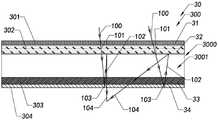
具体地,如图3和图4所示,所述基于波导的增强现实装置1可以包括用于发射图像光100的一图像源组件10、一波导组件20以及一平面折叠光组件30。所述波导组件20具有并排布置的耦入区域201和耦出区域202,并且所述波导组件20的所述耦入区域201对应于所述图像源组件10。所述平面折叠光组件30被设置于所述图像源组件10和所述波导组件20之间的光路中,其中所述平面折叠光组件30具有光焦度,并且所述平面折叠光组件30包括相互叠置的多个平面光学元件300,以通过所述多个平面光学元件300可选择偏转角度地折叠所述图像源组件10和所述波导组件20之间的光路,用于使来自所述图像源组件10的该图像光100在所述平面折叠光组件30内被多次折返的同时被会聚或发散之后,先从所述波导组件20的所述耦入区域201耦入,再从所述波导组件20的所述耦出区域202耦出,以导入人眼成像而观看到与所述图像光100对应的虚像。与此同时,外部的环境光线在透过所述波导组件20的所述耦出区域202后也能够导入人眼成像而观看到与环境光线对应的实像,从而获得增强现实体验。可以理解的是,本申请的该图像光100可以被实施为带有一定角度且携带图像信息的光线。Specifically, as shown in FIGS. 3 and 4 , the waveguide-based
值得注意的是,由于本发明的上述第一实施例的所述基于波导的增强现实装置1通过所述平面折叠光组件30可选择偏转角度地折叠所述光路,使得所述图像光100在所述平面折叠光组件30内沿着被折叠的所述光路多次折返且被会聚或发散,以在有限的空间内延长所述图像光100的光程的同时选择性地改变所述图像光100的会聚或发散角度,因此在提供同样长的光程和相同的会聚或发散效果时,所述平面折叠光组件30的厚度和尺寸将远远小于传统的透镜组(如图2所示的透镜组件22P)的厚度和尺寸,也就是说,所述平面折叠光组件30的体积和重量都远小于透镜组的体积和重量,进而使得整个装置的体积和重量均得以减小,有助于改善用户的佩戴舒适度。特别地,由于所述平面折叠光组件30的多个平面光学元件300均具有平整表面,且相互叠置,因此相比于现有的折返式增强现实设备10P中均具有弯曲表面的半反半透镜13P和曲面反射镜14P,本申请的基于波导的增强现实装置1在尺寸和紧凑程度上均优于现有的折返式增强现实设备10P,并且所述平面折叠光组件30更容易组装,极大地降低了所述基于波导的增强现实装置1的组装成本。It is worth noting that, because the waveguide-based
更具体地,如图3和图4所示,所述基于波导的增强现实装置1的所述平面折叠光组件30中的所述多个平面光学元件300可以包括一第一光学元件301、具有光焦度的一第二光学元件302、一第三光学元件303以及一第四光学元件304,并且所述第一光学元件301、所述第二光学元件302、所述第三光学元件303以及所述第四光学元件304被依次叠置于所述图像源组件10和所述波导组件20之间的光路中。所述第一光学元件301用于将该图像光100起偏为第一偏振图像光101。所述第二光学元件302用于透射该第一偏振图像光101,并且可选择角度地反射第二偏振图像光102。所述第三光学元件303用于将该第一偏振图像光101和该第二偏振图像光102与第三偏振图像光103和第四偏振图像光104相互转换。所述第四光学元件304用于反射该第三偏振图像光103,并且透射该第四偏振图像光104。可以理解的是,所述第二偏振图像光102在被所述第二光学元件302反射时,其入射角可以不等于反射角,而是按照预先设定的特定角度来反射所述第二偏振图像光102,以实现根据需要会聚或发散所述第二偏振图像光103。More specifically, as shown in FIGS. 3 and 4 , the plurality of planar
这样,如图4所示,首先,来自所述图像源组件10的所述图像光100传播至所述第一光学元件301以被所述第一光学元件301起偏为所述第一偏振图像光101;接着,所述第一偏振图像光101传播至所述第二光学元件302以在透过所述第二光学元件302后被所述第三光学元件303转换为所述第三偏振图像光103;然后,所述第三偏振图像光103传播至所述第四光学元件304以在被所述第四光学元件304反射回所述第三光学元件303后被所述第三光学元件303转换为所述第二偏振图像光102;之后,所述第二偏振图像光102传播至所述第二光学元件302以在被所述第二光学元件302可选择偏转角度地反射回所述第三光学元件303后被所述第三光学元件303转换为所述第四偏振图像光104;最后,所述第四偏振图像光104传播至所述第四光学元件304以透过所述第四光学元件304而传播至所述波导组件20的所述耦入区域201以从所述耦入区域201耦入所述波导组件20。可以理解的是,由于各种偏振态的图像光在所述平面折叠光组件30中的所述第二光学元件302和所述第四光学元件304之间来回折返,使得所述图像源组件10和所述波导组件20之间的光路在所述平面折叠光组件30内被折叠以实现在有限空间内延长光程的效果。In this way, as shown in FIG. 4 , first, the image light 100 from the image source assembly 10 propagates to the first
值得注意的是,所述第一偏振图像光101与所述第二偏振图像光102相互正交地偏振,并且所述第三偏振图像光103与所述第四偏振图像光104相互正交地偏振,以在确保折叠光路以延长光程的同时,使得所述第一光学元件301、所述第二光学元件302、所述第三光学元件303以及所述第四光学元件304能够利用现有的光学元件就能够实现上述功效,有助于降低所述平面折叠光组件30的制造难度。It is worth noting that the first polarized image light 101 and the second polarized image light 102 are mutually orthogonally polarized, and the third polarized image light 103 and the fourth polarized image light 104 are mutually orthogonally polarized polarization, so that the first
优选地,如图4所示,所述平面折叠光组件30中的所述第一光学元件301被实施为一圆偏振件31,其中所述圆偏振件31用于将图像光起偏为圆偏振光,例如,来自所述图像源组件10的所述图像光100能够被所述圆偏振件31起偏为左旋圆偏振图像光(即具有左旋圆偏振态的图像光)或右旋圆偏振图像光(即具有右旋圆偏振态的图像光)。特别地,所述圆偏振件31可以但不限于被实施为一圆偏振膜,有助于降低所述第一光学元件301的制造和组装难度。可以理解的是,所述圆偏振件31还可以被实施为诸如圆偏振片等其他形式的光学元件,只要能够将来自所述图像源组件10的所述图像光100起偏为所述第一偏振图像光101即可,本申请对此不再赘述。Preferably, as shown in FIG. 4 , the first
如图4所示,所述平面折叠光组件30中的所述第二光学元件302优选地被实施为一偏振体全息件32,其中所述偏振体全息件32被设计,用于透射所述左旋圆偏振图像光和所述右旋圆偏振图像光中的一种,并且可选择角度地反射所述左旋圆偏振图像光和所述右旋圆偏振图像光中的另一种。特别地,所述偏振体全息件32可以但不限于被实施为一偏振体全息膜,有助于降低所述第二光学元件302的制造和组装难度。As shown in FIG. 4 , the second
值得注意的是,所述偏振体全息件32是一种用全息技术制作的各向异性光学元件,一般为液晶排列形成的螺旋状光聚合物形成的光栅阵列结构,其具有角度选择性和偏振选择性,以在不同位置按照不同偏转角度来发射光线,使得所述偏振体全息件32的平面结构具有光焦度,以实现与曲面透镜一样的会聚或发散光线的功能。可以理解的是,所述偏振体全息件32也可以被实施为诸如偏振体全息片等其他形式的光学元件,只要能够透射所述第一偏振图像光101,并且反射所述第二偏振图像光102即可,本申请对此不再赘述。It is worth noting that the
如图4所示,所述平面折叠光组件30中的所述第三光学元件303优选地被实施为一1/4波片33,其中所述1/4波片33用于将线偏振光(如P偏振图像光或S偏振图像光)与圆偏振光(如所述左旋圆偏振图像光或所述右旋圆偏振图像光)相互转换。As shown in FIG. 4 , the third
如图4所示,所述平面折叠光组件30中的所述第四光学元件304优选地被实施为一偏振反射件34,其中所述偏振反射件34用于反射所述S偏振图像光和所述P偏振图像光中的一种,并透射所述S偏振图像光和所述P偏振图像光中的另一种。特别地,所述偏振反射件34可以但不限于被实施为一偏振反射膜,用于反射所述S偏振图像光,并透射所述P偏振图像光,有助于降低所述第四光学元件304的制造和组装难度。可以理解的是,所述偏振反射件34也可以被实施为诸如偏振分光片等其他形式的光学元件,只要能够透射所述第四偏振图像光104,并且反射所述第三偏振图像光103即可,本申请对此不再赘述。As shown in FIG. 4 , the fourth
示例性地,在本申请的第一示例中,如图4A所示,所述第一偏振图像光101和所述第二偏振图像光102可以依次被实施为具有左旋圆偏振态的图像光(简称左旋圆偏振图像光)和具有右旋圆偏振态的图像光(简称右旋圆偏振图像光),并且所述第三偏振图像光103和所述第四偏振图像光104对应地依次被实施为具有S偏振态的图像光(简称S偏振图像光)和具有P偏振态的图像光(简称P偏振图像光)。Exemplarily, in the first example of the present application, as shown in FIG. 4A , the first polarized image light 101 and the second polarized image light 102 may be sequentially implemented as image light with a left-handed circular polarization state ( referred to as left-handed circularly polarized image light) and image light having a right-handed circularly polarized state (referred to as right-handed circularly polarized image light), and the third polarized image light 103 and the fourth polarized image light 104 are sequentially implemented correspondingly. It is image light with S polarization state (referred to as S-polarized image light) and image light with P polarization state (referred to as P-polarized image light).
与此同时,在本申请的上述第一示例中,如图4A所示,所述平面折叠光组件30中的所述圆偏振件31用于将所述图像光100起偏为所述左旋圆偏振图像光;所述偏振体全息件32用于透射所述左旋圆偏振图像光,并可选择偏转角度地反射所述右旋圆偏振图像光;所述1/4波片33用于将所述P偏振图像光和所述S偏振图像光与所述左旋圆偏振图像光和右旋圆偏振图像光相互转换;所述偏振反射件34用于透射所述P偏振图像光,并反射所述S偏振图像光。Meanwhile, in the above-mentioned first example of the present application, as shown in FIG. 4A , the
这样,如图4A所示,首先,来自所述图像源组件10的所述图像光100传播至所述圆偏振件31以被所述圆偏振件31起偏为所述左旋圆偏振图像光;接着,所述左旋圆偏振图像光传播至所述偏振体全息件32以在透过所述偏振体全息件32后被所述1/4波片33转换为所述S偏振图像光;然后,所述S偏振图像光传播至所述偏振反射件34以在被所述偏振反射件34反射回所述1/4波片33后被所述1/4波片33转换为所述右旋圆偏振图像光;之后,所述右旋圆偏振图像光传播至所述偏振体全息件32以在被所述偏振体全息件32可选择偏转角度地反射回所述1/4波片33后被所述1/4波片33转换为所述P偏振图像光;最后,所述P偏振图像光传播至所述偏振反射件34以透过所述偏振反射件34而传播至所述波导组件20的所述耦入区域201以从所述耦入区域201耦入所述波导组件20,使得所述图像源组件10和所述波导组件20之间的光路在所述平面折叠光组件30内被可选择偏转角度地折叠以在实现在有限空间内延长光程的效果的同时,还能够根据需要会聚或发散图像光。In this way, as shown in FIG. 4A , first, the image light 100 from the image source assembly 10 propagates to the circular polarizer 31 to be polarized by the circular polarizer 31 into the left-handed circularly polarized image light; Next, the left-handed circularly polarized image light propagates to the polarizing body hologram 32 to be converted into the S-polarized image light by the quarter wave plate 33 after passing through the polarizing body hologram 32; then, The S-polarized image light propagates to the polarization reflector 34 to be converted into the right-handed circle by the quarter-wave plate 33 after being reflected back to the quarter-wave plate 33 by the polarization reflector 34 polarized image light; then, the right-handed circularly polarized image light propagates to the polarizing body hologram 32 to be reflected back to the quarter wave plate 33 by the polarizing body hologram 32 with a selectable deflection angle The 1/4 wave plate 33 is converted into the P-polarized image light; finally, the P-polarized image light propagates to the polarized reflector 34 to transmit to the waveguide assembly 20 through the polarized reflector 34 The coupling-in region 201 is coupled into the waveguide assembly 20 from the coupling-in region 201 , so that the optical path between the image source assembly 10 and the waveguide assembly 20 is blocked in the planar folded optical assembly 30 It can be folded with a selectable deflection angle to achieve the effect of extending the optical path in a limited space, while also condensing or diverging the image light as required.
值得注意的是,在本申请的第二示例中,如图4B所示,所述第一偏振图像光101和所述第二偏振图像光102也可以依次被实施为右旋圆偏振图像光和左旋圆偏振图像光,并且所述第三偏振图像光103和所述第四偏振图像光104仍然依次被实施为S偏振图像光和P偏振图像光。It is worth noting that, in the second example of the present application, as shown in FIG. 4B , the first polarized image light 101 and the second polarized image light 102 may also be sequentially implemented as right-handed circularly polarized image light and Left-handed circularly polarized image light, and the third polarized image light 103 and the fourth polarized image light 104 are still sequentially implemented as S-polarized image light and P-polarized image light.
与此同时,在本申请的上述第二示例中,如图4B所示,所述平面折叠光组件30中的所述圆偏振件31用于将所述图像光100起偏为所述右旋圆偏振图像光;所述平面折叠光组件30中的偏振体全息件32’被设计,用于透射所述右旋圆偏振图像光,并可选择偏转角度地反射所述左旋圆偏振图像光;所述1/4波片33用于将所述P偏振图像光和所述S偏振图像光与所述左旋圆偏振图像光和右旋圆偏振图像光相互转换;所述偏振反射件34用于透射所述P偏振图像光,并反射所述S偏振图像光。At the same time, in the above-mentioned second example of the present application, as shown in FIG. 4B , the
这样,如图4B所示,首先,来自所述图像源组件10的所述图像光100传播至所述圆偏振件31以被所述圆偏振件31起偏为所述右旋圆偏振图像光;接着,所述右旋圆偏振图像光传播至所述偏振体全息件32’以在透过所述偏振体全息件32’后被所述1/4波片33转换为所述S偏振图像光;然后,所述S偏振图像光传播至所述偏振反射件34以在被所述偏振反射件34反射回所述1/4波片33后被所述1/4波片33转换为所述左旋圆偏振图像光;之后,所述左旋圆偏振图像光传播至所述偏振体全息件32’以在被所述偏振体全息件32’可选择偏转角度地反射回所述1/4波片33后被所述1/4波片33转换为所述P偏振图像光;最后,所述P偏振图像光传播至所述偏振反射件34以透过所述偏振反射件34而传播至所述波导组件20的所述耦入区域201以从所述耦入区域201耦入所述波导组件20,仍能够使得所述图像源组件10和所述波导组件20之间的光路在所述平面折叠光组件30内被可选择偏转角度地折叠以在实现在有限空间内延长光程的效果的同时,还能够根据需要会聚或发散图像光。In this way, as shown in FIG. 4B , first, the image light 100 from the image source assembly 10 propagates to the
当然,在本申请的其他示例中,所述第三偏振图像光103和所述第四偏振图像光104也可以依次被实施为P偏振图像光和S偏振图像光。此时,相比于上述第一示例和上述第二示例,只需要将所述偏振反射件34调整为用于透射所述S偏振图像光,并反射所述P偏振图像光即可,本申请对此不再赘述。Of course, in other examples of the present application, the third polarized image light 103 and the fourth polarized image light 104 may also be sequentially implemented as P-polarized image light and S-polarized image light. At this time, compared with the above-mentioned first example and the above-mentioned second example, the
值得一提的是,根据本申请的上述第一实施例,所述波导组件20可以但不限于被实施为SRG(表面浮雕光栅)衍射波导或二维阵列波导等等,本申请对此不在赘述。It is worth mentioning that, according to the above-mentioned first embodiment of the present application, the
所述图像源组件10可以不限于被实施为自发光的OLED或Micro LED;也可以被实施为背光的LCD或LCOS,并利用LED或激光进行照明,本申请对此不再赘述。可以理解的是,当所述图像源组件10所发射的所述图像光100本身就为所述第一偏振图像光101时,所述平面折叠组件30中的所述第一光学元件301可以被省去,以便进一步减小所述平面折叠组件30的厚度。The image source assembly 10 may not be limited to be implemented as a self-luminous OLED or Micro LED; it may also be implemented as a backlight LCD or LCOS, and uses LEDs or lasers for illumination, which will not be repeated in this application. It can be understood that, when the
在本申请的上述实施例中,所述第二光学元件302和所述第三光学元件303优选地被间隔地叠置,以在所述第二光学元件302和所述第三光学元件303之间形成一透光间隙3000,使得所述第二光学元件302与所述第四光学元件304之间的距离变大,有助于增加所述平面折叠光组件30内的光程。In the above-mentioned embodiment of the present application, the second
更优选地,如图3所示,所述透光间隙3000被实施为一空气间隙3001,以在保证所述平面折叠光组件30的整体重量不增加的情况下,增加所述平面折叠光组件30内的光程;换言之,在所述第二光学元件302和所述第三光学元件303之间不设置其他光学元件,以在所述第二光学元件302和所述第三光学元件303之间形成所述空气间隙3001。此时,所述第一光学元件301与所述第二光学元件302可以相互紧贴,并且所述第三光学元件303与所述第四光学元件304可以相互紧贴。More preferably, as shown in FIG. 3 , the light-transmitting
值得注意的是,附图5示出了根据本发明的上述第一实施例的所述基于波导的增强现实装置1的第一变形实施方式。相比于根据本发明的上述第一实施例,根据本发明的所述第一变形实施方式的所述基于波导的增强现实装置1的不同之处在于:所述第三光学元件303和所述第四光学元件304被间隔地叠置,以在所述第三光学元件303和所述第四光学元件304之间形成所述透光间隙3000,仍能够使得所述第二光学元件302与所述第四光学元件304之间的距离变大,有助于增加所述平面折叠光组件30内的光程。此时,所述第一光学元件301、所述第二光学元件302以及所述第三光学元件303可以相互紧贴。It is worth noting that FIG. 5 shows a first variant implementation of the waveguide-based
附图6示出了根据本发明的上述第一实施例的所述基于波导的增强现实装置1的第二变形实施方式。相比于根据本发明的上述第一实施例,根据本发明的所述第二变形实施方式的所述基于波导的增强现实装置1的不同之处在于:所述平面折叠光组件30可以进一步包括一平面透光元件305,其中所述平面透光元件305被设置于所述透光间隙3000,并且所述平面透光元件305的折射率大于空气的折射率,以便在提供相同光程的情况下,所述平面透光元件305的厚度可以比所述空气间隙3001的厚度更薄,有助于进一步减小所述平面折叠光组件30的厚度。FIG. 6 shows a second variant embodiment of the waveguide-based
优选地,如图6所示,所述平面透光元件305被实施为一平面透镜35,其中所述平面透镜35具有一上平整表面351和一下平整表面352,并且所述第二光学元件302和所述第三光学元件303分别被对应地贴合于所述平面透镜35的所述上平整表面351和所述下平整表面352,以在保证所述第二光学元件302和所述第三光学元件303的平整度的同时,降低所述平面折叠光组件30的组装难度。Preferably, as shown in FIG. 6 , the plane light-transmitting
示例性地,当所述第二光学元件302为所述偏振体全息膜时,所述偏振体全息膜可以被镀于所述平面透镜35的所述上平整表面351,以确保所述偏振体全息膜具有较高的平整度。Exemplarily, when the second
当然,在本申请的其他示例中,所述第一光学元件301和所述第四光学元件304也可以分别被对应地贴合于所述第二光学元件302和所述第三光学元件303,以进一步降低所述平面折叠光组件30的组装难度。Of course, in other examples of the present application, the first
附图7示出了根据本发明的上述第一实施例的所述基于波导的增强现实装置1的第三变形实施方式。相比于根据本发明的上述第一实施例,根据本发明的所述第三变形实施方式的所述基于波导的增强现实装置1的不同之处在于:所述第二光学元件302与所述第四光学元件304的位置相互调换,并且所述第一光学元件301’用于将该图像光100起偏为所述第四偏振图像光104。换言之,所述平面折叠光组件30中的所述第一光学元件301’、所述第四光学元件304、所述第三光学元件303以及所述第二光学元件302依次被叠置于所述图像源组件10和所述波导组件20之间。FIG. 7 shows a third variant embodiment of the waveguide-based
优选地,如图7所示,所述第一光学元件301’被实施为一线偏振件31’,用于将该图像光100起偏为线偏振光,如P偏振图像光。当然,在本申请的其他示例中,所述线偏振件31’也可以用于将该图像光100起偏为S偏振图像光,此时所述第四光学元件304将透射S偏振图像光且反射P偏振图像光。Preferably, as shown in FIG. 7 , the first optical element 301' is implemented as a linear polarizer 31' for polarizing the
这样,如图7所示,首先,来自所述图像源组件10的所述图像光100传播至所述线偏振件31’以被所述线偏振件31’起偏为所述P偏振图像光(即所述第四偏振图像光104);接着,所述P偏振图像光传播至所述偏振反射件34以在透过所述偏振反射件34后被所述1/4波片33转换为所述左旋圆偏振图像光(即所述第二偏振图像光102);然后,所述左旋圆偏振图像光传播至所述偏振体全息件32以在被所述偏振体全息件32可选择偏转角度地反射回所述1/4波片33后被所述1/4波片33转换为所述S偏振图像光(即第三偏振图像光103);之后,所述S偏振图像光传播至所述偏振反射件34以在被所述偏振反射件34反射回所述1/4波片33后被所述1/4波片33转换为所述右旋圆偏振图像光(即第一偏振图像光101);最后,所述右旋圆偏振图像光传播至所述偏振体全息件32以透过所述偏振体全息件32而传播至所述波导组件20的所述耦入区域201以从所述耦入区域201耦入所述波导组件20,仍能够使得所述图像源组件10和所述波导组件20之间的光路在所述平面折叠光组件30内被可选择偏转角度地折叠以在实现在有限空间内延长光程的效果的同时,还能够根据需要会聚或发散图像光。In this way, as shown in FIG. 7 , first, the image light 100 from the image source assembly 10 propagates to the
值得一提的是,在本发明的上述第一实施例及其变形实施方式的所述基于波导的增强现实装置1中:所述平面折叠光组件30与所述波导组件20的所述耦入区域201相匹配地设置,也就是说,所述平面折叠光组件30对应于所述波导组件20的所述耦入区域201,使得经由所述平面折叠光组件30会聚或发散后的图像光与所述波导组件20的所述耦入区域201相匹配,以被从所述波导组件20的所述耦入区域201耦入所述波导组件20。It is worth mentioning that, in the waveguide-based
然而,由于所述平面折叠光组件30与所述波导组件20的所述耦入区域201相匹配,使得所述平面折叠光组件30只能被组装于在所述波导组件20的所述耦入区域201,因此这会给所述基于波导的增强现实装置1的组装带来诸多不便,如所述平面折叠光组件30与所述波导组件20的所述耦入区域201难以精准地对齐。特别地,当所述平面折叠光组件30中的所述透光间隙3000为所述空气间隙3001时,所述平面折叠光组件30则先需要利用组装支架进行单独地组装,以支撑所述多个平面光学元件300而保持足够的平整度,再将组装好的所述平面折叠光组件30安装于所述波导组件20的所述耦入区域201,但这样不仅会增加组装工序、增大组装难度,而且所述平面折叠光组件30的所述组装支架将遮挡用户的视线以影响用户的舒适体验。However, since the plane folded
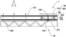
为了解决上述问题,本发明的第二实施例提供了一种基于波导的增强现实装置。具体地,如图8所示,相比于根据本申请的上述第一实施例,根据本申请的所述第二实施例的所述基于波导的增强现实装置1的不同之处在于:所述平面折叠光组件30同时与所述波导组件20的所述耦入区域201和所述耦出区域202相匹配地设置,也就是说,所述平面折叠光组件30同时对应于所述波导组件20的所述耦入区域201和所述耦出区域202,以便将所述平面折叠光组件30与所述波导组件20可以利用同一组装支架进行整体地组装,使得所述基于波导的增强现实装置1在外观上看起来和普通眼镜类似,即几毫米厚的平板,结构更紧凑,而不必担心所述组装支架影响用户的视线。In order to solve the above problems, a second embodiment of the present invention provides a waveguide-based augmented reality device. Specifically, as shown in FIG. 8 , compared with the above-mentioned first embodiment according to the present application, the waveguide-based
这样,与本申请的上述第一实施例相同的是:来自所述图像源组件10的所述图像光100经由所述平面折叠光组件30多次折返并转化为所述第四偏振图像光104以从所述波导组件20的所述耦入区域201耦入并从所述耦出区域202耦出所述波导组件20。而与本申请的上述第一实施例不同的是:从所述耦出区域202耦出的所述第四偏振图像光104将在透过所述第四光学元件304后传播至所述第三光学元件303以被转化为所述第一偏振图像光101;之后,所述第一偏振图像光101依次透过所述第二光学元件302和所述第一光学元件301以传播至人眼中形成虚像,仍能够使用户获得增强现实体验。可以理解的是,与本申请的上述第一实施例中的第一示例相同,本申请的所述第二实施例中所述第四偏振图像光104可以被实施为P偏振图像光,并且所述第一偏振图像光101被对应地实施为左旋圆偏振图像光。In this way, the same as the above-mentioned first embodiment of the present application is that the image light 100 from the image source assembly 10 is folded back multiple times through the plane folded
值得注意的是,由于从所述波导组件20的所述耦入区域201耦入所述波导组件20的图像光束通常是平行光,以确保所述图像光束在所述波导组件20内传导的光程保持一致,因此从所述波导组件20的所述耦出区域202耦出的图像光束因在所述平面折叠光组件30内未被可选择角度地反射而在入射至用户眼睛时仍然保持为平行光。而这些平行的图像光束虽然在导入视力正常的用户眼睛时形成清晰的虚像,但如果导入近视或远视用户的眼睛时却无法形成清晰的虚像,这就要求近视或远视用户在使用所述基于波导的增强现实装置1时不得不佩戴自己的近视或远视眼镜,很大程度地限制了近视或远视人群的使用和舒适体验。It is worth noting that, since the image beam coupled into the
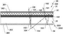
为了解决上述问题,本发明的第三实施例提供了一种基于波导的增强现实装置1,其能够满足近视或远视人群的需求,使其在无需佩戴近视或远视眼镜的情况下就能够获得较好的增强现实体验。具体地,如图9和图10所示,相比于根据本发明的上述第二实施例,根据本发明的所述第三实施例的所述基于波导的增强现实装置1A的不同之处在于:所述平面折叠光组件30A的所述第二光学元件302A具有并排布置的第一光学区域3021A和第二光学区域3022A,其中所述第二光学元件302A的所述第一光学区域3021A对应于所述波导组件20的所述耦入区域201,用于透射所述第一偏振图像光101,并可选择角度地反射所述第二偏振图像光102;其中所述第二光学元件302A的所述第二光学区域3022A对应于所述波导组件20的所述耦出区域202,用于透射所述第二偏振图像光102,并可选择角度地反射所述第一偏振图像光101。与此同时,所述平面折叠光组件30A的所述第一光学元件301A仅与所述波导组件20的所述耦入区域201相匹配地对应。In order to solve the above problems, the third embodiment of the present invention provides an
这样,与本申请的上述第二实施例类似的是:如图9和图10所示,首先,来自所述图像源组件10的所述图像光100传播至所述第一光学元件301以被所述第一光学元件301起偏为所述第一偏振图像光101;接着,所述第一偏振图像光101传播至所述第二光学元件302A的所述第一光学区域3021A以在透过所述第二光学元件302A的所述第一光学区域3021A后被所述第三光学元件303转换为所述第三偏振图像光103;然后,所述第三偏振图像光103传播至所述第四光学元件304以在被所述第四光学元件304反射回所述第三光学元件303后被所述第三光学元件303转换为所述第二偏振图像光102;之后,所述第二偏振图像光102传播至所述第二光学元件302A的所述第一光学区域3021A以在被所述第二光学元件302A的所述第一光学区域3021A可选择偏转角度地反射回所述第三光学元件303后被所述第三光学元件303转换为所述第四偏振图像光104;最后,所述第四偏振图像光104传播至所述第四光学元件304以透过所述第四光学元件304而传播至所述波导组件20的所述耦入区域201以从所述耦入区域201耦入所述波导组件20,进而在被所述波导组件20传导后从所述波导组件20的所述耦出区域202耦出所述波导组件20。In this way, similar to the above-mentioned second embodiment of the present application, as shown in FIG. 9 and FIG. 10 , first, the image light 100 from the image source assembly 10 propagates to the first optical element 301 to be The first optical element 301 is polarized to the first polarized image light 101; then, the first polarized image light 101 propagates to the first optical region 3021A of the second optical element 302A to transmit The first optical area 3021A of the second optical element 302A is converted into the third polarized image light 103 by the third optical element 303; then, the third polarized image light 103 propagates to the The fourth optical element 304 is converted into the second polarized image light 102 by the third optical element 303 after being reflected back to the third optical element 303 by the fourth optical element 304; after that, the second polarized image light 102 Image light 102 propagates to the first optical area 3021A of the second optical element 302A to be reflected back to the third optical area at a selectable deflection angle by the first optical area 3021A of the second optical element 302A The element 303 is then converted into the fourth polarized image light 104 by the third optical element 303; finally, the fourth polarized image light 104 propagates to the fourth optical element 304 to pass through the fourth optical element 304 and propagate to the coupling region 201 of the waveguide assembly 20 to be coupled into the waveguide assembly 20 from the coupling region 201 , and further, after being conducted by the waveguide assembly 20 , from the coupling region 20 of the waveguide assembly 20 The coupling-out region 202 is coupled out of the waveguide assembly 20 .
而与本申请的上述第二实施例不同的是:如图9和图10所示,首先,从所述耦出区域202耦出的所述第四偏振图像光104传播至所述第四光学元件304以在透过所述第四光学元件304后被所述第三光学元件303转化为所述第一偏振图像光101;其次,所述第一偏振图像光101传播至所述第二光学元件302A的所述第二光学区域3022A以在被所述第二光学元件302A的所述第二光学区域3022A反射回所述第三光学元件303后被所述第三光学元件303转换为所述第三偏振图像光103;之后,所述第三偏振图像光103传播至所述第四光学元件304以在被所述第四光学元件304反射回所述第三光学元件303后被所述第三光学元件303转换为所述第二偏振图像光102;最后,所述第二偏振图像光102先传播至所述第二光学元件302A的所述第二光学区域3022A以透过所述第二光学元件302A的所述第二光学区域3022A后,再传播至人眼中形成虚像,以使用户获得增强现实体验。The difference from the above-mentioned second embodiment of the present application is that, as shown in FIG. 9 and FIG. 10 , first, the fourth polarized image light 104 coupled out from the coupling-out region 202 propagates to the fourth optical The element 304 is converted into the first polarized image light 101 by the third optical element 303 after passing through the fourth optical element 304; secondly, the first polarized image light 101 propagates to the second optical element The second optical area 3022A of element 302A is converted to the third optical element 303 by the third optical element 303 after being reflected back to the third optical element 303 by the second optical area 3022A of the second optical element 302A The third polarized image light 103 ; after that, the third polarized image light 103 propagates to the fourth optical element 304 to be reflected by the fourth optical element 304 back to the third optical element 303 by the third optical element 303 The three optical elements 303 are converted into the second polarized image light 102; finally, the second polarized image light 102 first propagates to the second optical area 3022A of the second optical element 302A to pass through the second After the second optical area 3022A of the optical element 302A is transmitted to the human eye to form a virtual image, so that the user can obtain an augmented reality experience.
值得注意的是,相比于根据本申请的上述第二实施例,根据本申请的所述第三实施例的所述基于波导的增强现实装置1A的所述平面折叠光组件30A在对从所述耦出区域202耦出的图像光束进行多次折返的同时,还会可选择角度地反射该图像光束以发散或会聚光线,也就是说,与所述波导组件20的所述耦出区域202对应的所述平面折叠光组件30A利用折叠光路来实现光束的会聚或发散,使得从所述波导组件20的所述耦出区域202耦出的平行光束在通过所述平面折叠光组件30A之后形成会聚光束(如图9所示)或发散光束(如图10所示)以导入人眼成像,有助于使远视或近视人群在不佩戴远视或近视眼镜的情况下就能够看到清晰的虚像。与此同时,环境光线在穿过所述基于波导的增强现实装置1A时也会被会聚或发散,使得远视或近视人群在不佩戴远视或近视眼镜的情况下也能够看到清晰的环境实像,从而能够很好地满足远视或近视人群的需求,使其在无需佩戴远视或近视眼镜的情况下就能够获得较好的增强现实体验。It is worth noting that, compared with the above-mentioned second embodiment according to the present application, the planar folded
示例性地,如图9和图10所示,所述平面折叠光组件30A中所述第二光学元件302A包括偏振敏感方向相反的第一偏振体全息件321A和第二偏振体全息件322A,其中所述第一偏振体全息件321和所述第二偏振体全息件322A被并排地设置以分别提供所述第一光学区域3021A和所述第二光学区域3022A,其中所述第一偏振体全息件321A与上述偏振体全息件32相同,用于透射所述左旋圆偏振图像光,并可选择偏转角度地反射所述右旋圆偏振图像光;其中所述第二偏振体全息件322A与上述偏振体全息件32’相同,用于透射所述右旋圆偏振图像光,并可选择偏转角度地反射所述左旋圆偏振图像光。Exemplarily, as shown in FIG. 9 and FIG. 10 , the second
优选地,所述第二光学元件302A中的所述第一偏振体全息件321A一体地连接于所述第二偏振体全息件322A,以简化所述平面折叠光组件30A的组装。当然,在本申请的其他示例中,所述第二光学元件302A中的所述第一偏振体全息件321A也可以与所述第二偏振体全息件322A被间隔地布置,以便分别制作所述第一偏振体全息件321A和所述第二偏振体全息件322A。Preferably, the
值得注意的是,在本发明的上述实施例中,由于所述基于波导的增强现实装置1A的屈光度是由所述第二光学元件302A的光焦度(即反射角度)来决定的,因此,所述基于波导的增强现实装置1A通过选用具有不同光焦度的所述第二光学元件302A来获得不同的屈光度,以满足不同的近视或远视人群的需求。It is worth noting that, in the above-mentioned embodiment of the present invention, since the diopter of the waveguide-based
根据本发明的另一方面,本发明进一步提供了基于波导的增强现实装置的制造方法。具体地,如图11所示,所述基于波导的增强现实装置的制造方法,可以包括步骤:According to another aspect of the present invention, the present invention further provides a method of fabricating a waveguide-based augmented reality device. Specifically, as shown in FIG. 11 , the method for manufacturing the waveguide-based augmented reality device may include the steps:
S110:对应地设置用于发射图像光的一图像源组件于一波导组件的耦入区域;和S110: correspondingly disposing an image source assembly for emitting image light in a coupling region of a waveguide assembly; and
S120:设置具有光焦度的一平面折叠光组件于该图像源组件和该波导组件之间的光路中,其中所述平面折叠光组件包括相互叠置的多个平面光学元件,以通过所述多个平面光学元件可选择偏转角度地折叠所述图像源组件和所述波导组件之间的光路,用于使来自所述图像源组件的该图像光在所述平面折叠光组件内被多次折返的同时被会聚或发散之后,先从所述波导组件的所述耦入区域耦入,再从所述波导组件的所述耦出区域耦出。S120: Disposing a plane folded optical component with optical power in the optical path between the image source component and the waveguide component, wherein the plane folded optical component includes a plurality of plane optical elements superposed on each other, so as to pass the a plurality of planar optical elements selectively deflected to fold the light path between the image source assembly and the waveguide assembly for causing the image light from the image source assembly to be multiplexed within the planar folded light assembly After being converged or diverged while being folded back, it is first coupled in from the coupling-in region of the waveguide assembly, and then coupled out from the coupling-out region of the waveguide assembly.
值得注意的是,在所述基于波导的增强现实装置的制造方法的所述步骤S120中:依次叠置一第一光学元件、一第二光学元件、一第三光学元件以及一第四光学元件以形成所述平面折叠光组件。It is worth noting that, in the step S120 of the manufacturing method of the waveguide-based augmented reality device: a first optical element, a second optical element, a third optical element and a fourth optical element are stacked in sequence to form the planar folded light assembly.
值得一提的是,根据本发明的另一方面,本发明进一步提供了一种近眼显示方法。具体地,如图12所示,所述近眼显示方法,可以包括步骤:It is worth mentioning that, according to another aspect of the present invention, the present invention further provides a near-eye display method. Specifically, as shown in FIG. 12 , the near-eye display method may include the steps:
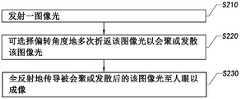
S210:发射一图像光;S210: emit an image light;
S220:可选择偏转角度地多次折返该图像光以会聚或发散该图像光;以及S230:全反射地传导被会聚或发散后的该图像光至人眼以成像。S220 : returning the image light multiple times with a selectable deflection angle to condense or diverging the image light; and S230 : transmitting the condensed or diverging image light to the human eye in total reflection for imaging.
在本申请的一示例中,如图13A所示,所述近眼显示方法的所述步骤S220,可以包括步骤:In an example of the present application, as shown in FIG. 13A , the step S220 of the near-eye display method may include the steps of:
S221:起偏该图像光以形成一第一偏振图像光;S221: polarize the image light to form a first polarized image light;
S222:透射该第一偏振图像光以转换为一第三偏振图像光;S222: Transmitting the first polarized image light to convert into a third polarized image light;
S223:反射回该第三偏振图像光以转换为一第二偏振图像光,其中该第二偏振图像光与该第一偏振图像光相互正交地偏振;S223: Reflecting the third polarized image light back to be converted into a second polarized image light, wherein the second polarized image light and the first polarized image light are polarized orthogonally to each other;
S224:可选择角度地反射回该第二偏振图像光以发散或会聚该第二偏振图像光;以及S224: Selectably reflect back the second polarized image light to diverge or converge the second polarized image light; and
S225:转换该第二偏振图像光以形成一第四偏振图像光,其中该第四偏振图像光与该第三偏振图像光相互正交地偏振。S225: Convert the second polarized image light to form a fourth polarized image light, wherein the fourth polarized image light and the third polarized image light are polarized orthogonally to each other.
在本申请的另一示例中,如图13B所示,所述近眼显示方法的所述步骤S220,可以包括步骤:In another example of the present application, as shown in FIG. 13B , the step S220 of the near-eye display method may include the steps of:
S221’:起偏该图像光以形成一第四偏振图像光;S221': polarize the image light to form a fourth polarized image light;
S222’:透射该第四偏振图像光以转换为一第二偏振图像光;S222': transmit the fourth polarized image light to be converted into a second polarized image light;
S223’:可选择角度地反射回该第二偏振图像光以发散或会聚该第二偏振图像光;S223': selectably reflect back the second polarized image light to diverge or converge the second polarized image light;
S224’:转换该第二偏振图像光以形成一第三偏振图像光,其中该第三偏振图像光与该第四偏振图像光相互正交地偏振;以及S224': Convert the second polarized image light to form a third polarized image light, wherein the third polarized image light and the fourth polarized image light are polarized orthogonally to each other; and
S225’:反射回该第三偏振图像光以转换为一第一偏振图像光,其中该第一偏振图像光与该第二偏振图像光相互正交地偏振。S225': The third polarized image light is reflected back to be converted into a first polarized image light, wherein the first polarized image light and the second polarized image light are polarized orthogonally to each other.
值得注意的是,如图14所示,所述近眼显示方法的所述步骤S230,可以包括步骤:It is worth noting that, as shown in FIG. 14 , the step S230 of the near-eye display method may include the steps of:
S231:耦入该第四偏振图像光;S231: coupling into the fourth polarized image light;
S232:全反射地传导被耦入的该第四偏振图像光;以及S232: Conducting the coupled fourth polarized image light in total reflection; and
S233:耦出被全反射地传导的该第四偏振图像光。S233: Coupling out the fourth polarized image light that is conducted in a total reflection manner.
优选地,如图14所示,所述近眼显示方法的所述步骤S230,进一步包括步骤:Preferably, as shown in FIG. 14 , the step S230 of the near-eye display method further includes the steps of:
S234:透射被耦出的该第四偏振图像光以转换为该第一偏振图像光;S234: Transmit the coupled out fourth polarized image light to be converted into the first polarized image light;
S235:可选择角度地反射回该第一偏振图像光以发散或会聚该第一偏振图像光;S235: Selectably reflect back the first polarized image light to diverge or converge the first polarized image light;
S236:转换该第一偏振图像光以形成该第三偏振图像光;以及S236: Convert the first polarized image light to form the third polarized image light; and
S237:反射回该第三偏振图像光以转换为该第二偏振图像光而传播至人眼成像。S237: Reflect the third polarized image light back to be converted into the second polarized image light and propagate to the human eye for imaging.
本领域的技术人员应理解,上述描述及附图中所示的本发明的实施例只作为举例而并不限制本发明。本发明的目的已经完整并有效地实现。本发明的功能及结构原理已在实施例中展示和说明,在没有背离所述原理下,本发明的实施方式可以有任何变形或修改。It should be understood by those skilled in the art that the embodiments of the present invention shown in the above description and the accompanying drawings are only examples and do not limit the present invention. The objects of the present invention have been fully and effectively achieved. The functional and structural principles of the present invention have been shown and described in the embodiments, and the embodiments of the present invention may be modified or modified in any way without departing from the principles.
Claims (21)
Translated fromChinesePriority Applications (2)
| Application Number | Priority Date | Filing Date | Title |
|---|---|---|---|
| CN202011607192.4ACN114690414B (en) | 2020-12-30 | 2020-12-30 | Waveguide-based augmented reality device and method |
| PCT/CN2021/135437WO2022143011A1 (en) | 2020-12-30 | 2021-12-03 | Waveguide-based augmented reality apparatus and method therefor |
Applications Claiming Priority (1)
| Application Number | Priority Date | Filing Date | Title |
|---|---|---|---|
| CN202011607192.4ACN114690414B (en) | 2020-12-30 | 2020-12-30 | Waveguide-based augmented reality device and method |
Publications (2)
| Publication Number | Publication Date |
|---|---|
| CN114690414Atrue CN114690414A (en) | 2022-07-01 |
| CN114690414B CN114690414B (en) | 2025-09-02 |
Family
ID=82131942
Family Applications (1)
| Application Number | Title | Priority Date | Filing Date |
|---|---|---|---|
| CN202011607192.4AActiveCN114690414B (en) | 2020-12-30 | 2020-12-30 | Waveguide-based augmented reality device and method |
Country Status (2)
| Country | Link |
|---|---|
| CN (1) | CN114690414B (en) |
| WO (1) | WO2022143011A1 (en) |
Cited By (1)
| Publication number | Priority date | Publication date | Assignee | Title |
|---|---|---|---|---|
| CN115616788A (en)* | 2022-12-02 | 2023-01-17 | 杭州光粒科技有限公司 | Holographic optical module, near-to-eye display system and augmented reality wearing equipment |
Families Citing this family (2)
| Publication number | Priority date | Publication date | Assignee | Title |
|---|---|---|---|---|
| CN115439422B (en)* | 2022-08-21 | 2023-03-28 | 哈尔滨理工大学 | Two-dimensional space differential operation and image edge detection method and device |
| CN118938469B (en)* | 2024-10-15 | 2025-02-28 | 歌尔光学科技有限公司 | A method for setting the function of a polarization selection layer, a diffraction optical waveguide, a display device, an electronic device and a storage medium |
Citations (9)
| Publication number | Priority date | Publication date | Assignee | Title |
|---|---|---|---|---|
| JP2016105177A (en)* | 2015-12-24 | 2016-06-09 | ソニー株式会社 | Display device |
| CN108803031A (en)* | 2018-05-29 | 2018-11-13 | 成都理想境界科技有限公司 | A kind of nearly eye display device and equipment, zoom module and Zooming method |
| CN110352370A (en)* | 2017-03-07 | 2019-10-18 | 苹果公司 | Wear-type display system |
| CN110471185A (en)* | 2019-08-28 | 2019-11-19 | 瑞声通讯科技(常州)有限公司 | Waveguide augmented reality display device |
| WO2019221875A1 (en)* | 2018-05-18 | 2019-11-21 | Facebook Technologies, Llc | Eye tracking based on waveguide imaging |
| CN111240091A (en)* | 2020-02-24 | 2020-06-05 | 京东方科技集团股份有限公司 | Transparent display device and manufacturing method thereof |
| CN211878327U (en)* | 2020-03-24 | 2020-11-06 | 深圳铅笔视界科技有限公司 | Near-to-eye display device and glasses |
| CN112136084A (en)* | 2018-05-18 | 2020-12-25 | 脸谱科技有限责任公司 | Optical assembly with polarizer holographic element |
| CN213814151U (en)* | 2020-12-30 | 2021-07-27 | 舜宇光学(浙江)研究院有限公司 | Augmented reality device based on waveguide |
Family Cites Families (2)
| Publication number | Priority date | Publication date | Assignee | Title |
|---|---|---|---|---|
| US11378811B2 (en)* | 2018-06-18 | 2022-07-05 | Facebook Technologies, Llc | Optical assembly with curved reflective polarizer for head mounted display |
| KR102064688B1 (en)* | 2018-12-28 | 2020-01-09 | 세종대학교산학협력단 | Integral imaging system using geometric phase lens and method for enhancement of expressible depth range thereof |
- 2020
- 2020-12-30CNCN202011607192.4Apatent/CN114690414B/enactiveActive
- 2021
- 2021-12-03WOPCT/CN2021/135437patent/WO2022143011A1/ennot_activeCeased
Patent Citations (9)
| Publication number | Priority date | Publication date | Assignee | Title |
|---|---|---|---|---|
| JP2016105177A (en)* | 2015-12-24 | 2016-06-09 | ソニー株式会社 | Display device |
| CN110352370A (en)* | 2017-03-07 | 2019-10-18 | 苹果公司 | Wear-type display system |
| WO2019221875A1 (en)* | 2018-05-18 | 2019-11-21 | Facebook Technologies, Llc | Eye tracking based on waveguide imaging |
| CN112136084A (en)* | 2018-05-18 | 2020-12-25 | 脸谱科技有限责任公司 | Optical assembly with polarizer holographic element |
| CN108803031A (en)* | 2018-05-29 | 2018-11-13 | 成都理想境界科技有限公司 | A kind of nearly eye display device and equipment, zoom module and Zooming method |
| CN110471185A (en)* | 2019-08-28 | 2019-11-19 | 瑞声通讯科技(常州)有限公司 | Waveguide augmented reality display device |
| CN111240091A (en)* | 2020-02-24 | 2020-06-05 | 京东方科技集团股份有限公司 | Transparent display device and manufacturing method thereof |
| CN211878327U (en)* | 2020-03-24 | 2020-11-06 | 深圳铅笔视界科技有限公司 | Near-to-eye display device and glasses |
| CN213814151U (en)* | 2020-12-30 | 2021-07-27 | 舜宇光学(浙江)研究院有限公司 | Augmented reality device based on waveguide |
Cited By (2)
| Publication number | Priority date | Publication date | Assignee | Title |
|---|---|---|---|---|
| CN115616788A (en)* | 2022-12-02 | 2023-01-17 | 杭州光粒科技有限公司 | Holographic optical module, near-to-eye display system and augmented reality wearing equipment |
| CN115616788B (en)* | 2022-12-02 | 2024-05-24 | 杭州光粒科技有限公司 | Holographic optical module, near-to-eye display system and augmented reality wearable device |
Also Published As
| Publication number | Publication date |
|---|---|
| CN114690414B (en) | 2025-09-02 |
| WO2022143011A1 (en) | 2022-07-07 |
Similar Documents
| Publication | Publication Date | Title |
|---|---|---|
| JP7285579B2 (en) | Augmented reality device and optical system therefor | |
| KR101111742B1 (en) | Image display device | |
| EP2124087B1 (en) | Substrate-guided imaging lens with first and second substrate | |
| WO2022143011A1 (en) | Waveguide-based augmented reality apparatus and method therefor | |
| KR20040097367A (en) | Image display unit | |
| WO2008129539A2 (en) | A collimating optical device and system | |
| KR102129669B1 (en) | Optical system of see-through head mounted display having total internal reflection element | |
| CN114942489A (en) | Optical module and head-mounted display device | |
| CN215986726U (en) | Augmented reality display system | |
| WO2021042891A1 (en) | Near-eye display optical system and near-eye display device | |
| CN110646942A (en) | Ultrathin optical amplification module and application thereof | |
| TWM596873U (en) | Optical system of miniature head-mounted display | |
| TW202332960A (en) | Waveguide with polarization volume hologram grating | |
| CN114660816A (en) | Optical device and AR apparatus | |
| US20250155714A1 (en) | Optical device for augmented reality using polarizing optical element | |
| CN213814151U (en) | Augmented reality device based on waveguide | |
| CN211506032U (en) | Near-to-eye display device | |
| CN117389050A (en) | Optical system and optical apparatus | |
| US20250147217A1 (en) | Optical display apparatus | |
| CN118759628B (en) | Optical waveguide assembly and near-to-eye display device | |
| CN112946884A (en) | Near-eye display device and method of manufacturing the same | |
| CN219799825U (en) | Light guide system, light source device and display equipment | |
| CN214846040U (en) | Near-to-eye display device | |
| CN215494361U (en) | Near-to-eye display device | |
| CN113126299B (en) | Projection ray apparatus and head-mounted smart machine |
Legal Events
| Date | Code | Title | Description |
|---|---|---|---|
| PB01 | Publication | ||
| PB01 | Publication | ||
| SE01 | Entry into force of request for substantive examination | ||
| SE01 | Entry into force of request for substantive examination | ||
| EE01 | Entry into force of recordation of patent licensing contract | Application publication date:20220701 Assignee:Zhejiang Shunwei Technology Co.,Ltd. Assignor:SUNNY OPTICAL (ZHEJIANG) RESEARCH INSTITUTE Co.,Ltd. Contract record no.:X2024330000055 Denomination of invention:Waveguide based augmented reality device and its method License type:Common License Record date:20240515 | |
| EE01 | Entry into force of recordation of patent licensing contract | ||
| GR01 | Patent grant |