CN114689325A - Test method for filling and degassing of truck cooling system - Google Patents
Test method for filling and degassing of truck cooling systemDownload PDFInfo
- Publication number
- CN114689325A CN114689325ACN202210295582.5ACN202210295582ACN114689325ACN 114689325 ACN114689325 ACN 114689325ACN 202210295582 ACN202210295582 ACN 202210295582ACN 114689325 ACN114689325 ACN 114689325A
- Authority
- CN
- China
- Prior art keywords
- degassing
- filling
- pipe
- control valve
- test method
- Prior art date
- Legal status (The legal status is an assumption and is not a legal conclusion. Google has not performed a legal analysis and makes no representation as to the accuracy of the status listed.)
- Pending
Links
Images

Classifications
- G—PHYSICS
- G01—MEASURING; TESTING
- G01M—TESTING STATIC OR DYNAMIC BALANCE OF MACHINES OR STRUCTURES; TESTING OF STRUCTURES OR APPARATUS, NOT OTHERWISE PROVIDED FOR
- G01M15/00—Testing of engines
- G01M15/04—Testing internal-combustion engines
- G—PHYSICS
- G01—MEASURING; TESTING
- G01M—TESTING STATIC OR DYNAMIC BALANCE OF MACHINES OR STRUCTURES; TESTING OF STRUCTURES OR APPARATUS, NOT OTHERWISE PROVIDED FOR
- G01M17/00—Testing of vehicles
- G01M17/007—Wheeled or endless-tracked vehicles
Landscapes
- Physics & Mathematics (AREA)
- General Physics & Mathematics (AREA)
- Chemical & Material Sciences (AREA)
- Engineering & Computer Science (AREA)
- Combustion & Propulsion (AREA)
- Filling Or Discharging Of Gas Storage Vessels (AREA)
Abstract
Translated fromChinese
Description
Translated fromChinese技术领域technical field
本发明涉及车辆加注除气技术领域,尤其涉及一种用于卡车冷却系统加注除气的试验方法。The invention relates to the technical field of vehicle filling and degassing, in particular to a test method for filling and degassing a truck cooling system.
背景技术Background technique
为保证重卡的冷却系统发挥正常,冷却系统需要具备除气性能,常用加注除气试验来判定,公开号为CN105174184B的专利公开了一种发动机防冻液加注设备及加注方法,其中发动机防冻液加注设备包括:设置于加注台架上的防冻液加注桶;与防冻液加注桶连接的用于将防冻液加注至发动机内的一电动油泵;连接于电动油泵与发动机之间的用于向发动机注入防冻液的加注管路;连接于发动机与防冻液加注桶之间的用于向防冻液加注桶回流防冻液排除发动机冷却系统内空气的回流管路,以及用于检测发动机冷却系统内空气是否排尽的检测装置,回流管路设置有透明导管,回流管路上还设置有用于检测回流管路内是否有空气残留的空气检测设备,如气体传感器,当空气检测设备检测到回流管路内无空气残留时,表明发动机冷却系统内的空气被除尽。该空气检测设备安装比较麻烦,费用较高。现有技术中也会采用高速相机观察透明导管内是否存有气泡,以判断冷却系统除气是否正常,该检测方式也存在费用较高的缺陷。In order to ensure the normal functioning of the cooling system of the heavy truck, the cooling system needs to have degassing performance, which is usually determined by the filling and degassing test. The patent publication number CN105174184B discloses an engine antifreeze filling equipment and filling method, wherein the engine is antifreeze. The liquid filling equipment includes: an antifreeze filling bucket arranged on the filling table; an electric oil pump connected with the antifreeze filling bucket for filling antifreeze into the engine; connected between the electric oil pump and the engine. The filling line between the engine and the antifreeze liquid is used to inject antifreeze into the engine; the return line connected between the engine and the antifreeze filling tank is used to return antifreeze to the antifreeze filling tank to remove the air in the engine cooling system, and A detection device used to detect whether the air in the engine cooling system is exhausted. The return line is provided with a transparent conduit, and the return line is also provided with an air detection device for detecting whether there is air remaining in the return line, such as a gas sensor. When the detection equipment detects that there is no air remaining in the return line, it indicates that the air in the engine cooling system has been removed. The installation of the air detection equipment is troublesome and expensive. In the prior art, a high-speed camera is also used to observe whether there are air bubbles in the transparent conduit, so as to judge whether the degassing of the cooling system is normal, and this detection method also has the disadvantage of high cost.
发明内容SUMMARY OF THE INVENTION
本发明提供一种用于卡车冷却系统加注除气的试验方法,用以解决现有技术中加检测注管内气泡的费用较高的问题。The invention provides a test method for filling and degassing a truck cooling system, which is used to solve the problem of high cost of adding and detecting air bubbles in the injection pipe in the prior art.
本发明提供一种用于卡车冷却系统加注除气的试验方法,包括如下步骤:The invention provides a test method for filling and degassing a truck cooling system, comprising the following steps:
在加注管上并联一个支管,在所述支管上设置第一流量控制阀和第一观察窗;A branch pipe is connected in parallel with the filling pipe, and a first flow control valve and a first observation window are arranged on the branch pipe;
调节所述第一流量控制阀调节支管内的冷冻液的流速,使所述支管内的冷冻液的流速小于加注管内的冷冻液的流速;通过所述第一观察窗观察支管内是否有气泡,以判断膨胀水箱的除气性能是否正常。Adjust the flow rate of the refrigerant in the branch pipe by adjusting the first flow control valve, so that the flow rate of the refrigerant in the branch pipe is less than the flow rate of the refrigerant in the filling pipe; observe whether there are air bubbles in the branch pipe through the first observation window , to judge whether the degassing performance of the expansion tank is normal.
根据本发明提供的一种用于卡车冷却系统加注除气的试验方法,在发动机与膨胀水箱之间的第一除气管上设置第二观察窗和第二流量控制阀,当所述膨胀水箱除气性能不足时,根据所述第二观察窗观察第一除气管内的气泡情况,操作所述第二流量控制阀调节进入膨胀水箱的冷冻液的流速。According to a test method for filling and degassing a truck cooling system provided by the present invention, a second observation window and a second flow control valve are arranged on the first degassing pipe between the engine and the expansion tank. When the degassing performance is insufficient, the air bubbles in the first degassing pipe are observed according to the second observation window, and the second flow control valve is operated to adjust the flow rate of the refrigerant entering the expansion tank.
根据本发明提供的一种用于卡车冷却系统加注除气的试验方法,在散热器与膨胀水箱之间的第二除气管上设置第三观察窗和第三流量控制阀,当所述膨胀水箱除气性能不足时,根据所述第三观察窗观察第二除气管内的气泡情况,操作所述第三流量控制阀调节进入膨胀水箱的冷冻液的流速。According to a test method for filling and degassing a truck cooling system provided by the present invention, a third observation window and a third flow control valve are arranged on the second degassing pipe between the radiator and the expansion tank. When the degassing performance of the water tank is insufficient, the air bubbles in the second degassing pipe are observed according to the third observation window, and the third flow control valve is operated to adjust the flow rate of the refrigerant entering the expansion water tank.
根据本发明提供的一种用于卡车冷却系统加注除气的试验方法,所述加注管上设置有透明管。According to a test method for filling and degassing a truck cooling system provided by the present invention, the filling pipe is provided with a transparent pipe.
根据本发明提供的一种用于卡车冷却系统加注除气的试验方法,所述第一流量控制阀、第二流量控制阀和第三流量控制阀均为节流阀。According to a test method for filling and degassing a truck cooling system provided by the present invention, the first flow control valve, the second flow control valve and the third flow control valve are all throttle valves.
根据本发明提供的一种用于卡车冷却系统加注除气的试验方法,所述第一观察窗、第二观察窗和第三观察窗分别为设置在支管、第一除气管和第二除气管上的透明管。According to a test method for filling and degassing a truck cooling system provided by the present invention, the first observation window, the second observation window and the third observation window are respectively provided in the branch pipe, the first degassing pipe and the second degassing pipe. Transparent tube on the trachea.
根据本发明提供的一种用于卡车冷却系统加注除气的试验方法,所述膨胀水箱内设有液位观察窗。According to a test method for filling and degassing a truck cooling system provided by the present invention, a liquid level observation window is provided in the expansion tank.
根据本发明提供的一种用于卡车冷却系统加注除气的试验方法,所述膨胀水箱的上端设有压力盖。According to a test method for filling and degassing a truck cooling system provided by the present invention, the upper end of the expansion tank is provided with a pressure cover.
根据本发明提供的一种用于卡车冷却系统加注除气的试验方法,还包括节温器,所述第一除气管设于节温器与膨胀水箱之间,所述散热器与节温器之间连接有进水管。According to a test method for filling and degassing a truck cooling system provided by the present invention, it further includes a thermostat, the first degassing pipe is arranged between the thermostat and the expansion tank, and the radiator is connected to the thermostat. A water inlet pipe is connected between the devices.
根据本发明提供的一种用于卡车冷却系统加注除气的试验方法,所述发动机内设有水泵,所述水泵与散热器之间连通有出水管,所述加注管的一端与出水管连通,另一端与膨胀水箱连通。According to a test method for filling and degassing a truck cooling system provided by the present invention, the engine is provided with a water pump, a water outlet pipe is communicated between the water pump and the radiator, and one end of the filling pipe is connected to the outlet pipe. The water pipe is communicated, and the other end is communicated with the expansion water tank.
本发明通过在加注管处并联支管,在支管上设置第一流量控制阀和第一观察窗,调节第一流量控制阀降低支管内冷冻液的流速,以便通过第一观察窗观察支管内的气泡情况,从而确定加注管内气泡情况,进而判断膨胀水箱的除气性能,相对于高速相机观察,该检验方式投入少、成本低和易于观察;其次,试验方法简单易于实施。In the present invention, the branch pipes are connected in parallel at the filling pipe, the first flow control valve and the first observation window are arranged on the branch pipe, and the first flow control valve is adjusted to reduce the flow rate of the refrigerant in the branch pipe, so as to observe the flow rate in the branch pipe through the first observation window. Compared with high-speed camera observation, this inspection method has less investment, low cost and easy observation; secondly, the test method is simple and easy to implement.
附图说明Description of drawings
为了更清楚地说明本发明或现有技术中的技术方案,下面将对实施例或现有技术描述中所需要使用的附图作简单地介绍,显而易见地,下面描述中的附图是本发明的一些实施例,对于本领域普通技术人员来讲,在不付出创造性劳动的前提下,还可以根据这些附图获得其他的附图。In order to explain the present invention or the technical solutions in the prior art more clearly, the following briefly introduces the accompanying drawings that need to be used in the description of the embodiments or the prior art. Obviously, the drawings in the following description are of the present invention. For some embodiments of the present invention, for those of ordinary skill in the art, other drawings can also be obtained from these drawings without any creative effort.
图1是本发明提供的用于卡车冷却系统加注除气的试验方法的工作流程图;Fig. 1 is the working flow chart of the test method for filling and degassing of truck cooling system provided by the present invention;
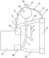
图2是本发明提供的用于卡车冷却系统加注除气的试验方法中所使用的加注除气结构示意图;2 is a schematic diagram of the filling and degassing structure used in the test method for filling and degassing of a truck cooling system provided by the present invention;
附图标记:Reference number:
1:加注管; 2:支管; 3:第一流量控制阀;1: Filling pipe; 2: Branch pipe; 3: First flow control valve;
4:透明管; 5:发动机; 6:膨胀水箱;4: Transparent tube; 5: Engine; 6: Expansion tank;
7:第一除气管; 8:第二流量控制阀; 9:散热器;7: The first degassing pipe; 8: The second flow control valve; 9: The radiator;
10:第二除气管; 11:第三流量控制阀;12:液位观察窗;10: The second degassing pipe; 11: The third flow control valve; 12: The liquid level observation window;
13:压力盖; 14:节温器; 15:进水管;13: pressure cover; 14: thermostat; 15: water inlet pipe;
16:水泵; 17:出水管。16: Water pump; 17: Outlet pipe.
具体实施方式Detailed ways
为使本发明的目的、技术方案和优点更加清楚,下面将结合本发明中的附图,对本发明中的技术方案进行清楚、完整地描述,显然,所描述的实施例是本发明一部分实施例,而不是全部的实施例。基于本发明中的实施例,本领域普通技术人员在没有作出创造性劳动前提下所获得的所有其他实施例,都属于本发明保护的范围。In order to make the objectives, technical solutions and advantages of the present invention clearer, the technical solutions in the present invention will be clearly and completely described below with reference to the accompanying drawings. Obviously, the described embodiments are part of the embodiments of the present invention. , not all examples. Based on the embodiments of the present invention, all other embodiments obtained by those of ordinary skill in the art without creative efforts shall fall within the protection scope of the present invention.
下面结合图1-图2描述本发明的用于卡车冷却系统加注除气的试验方法,本实施例提供了一种用于卡车冷却系统加注除气的试验方法,包括如下步骤:The test method for filling and degassing a truck cooling system of the present invention is described below with reference to FIGS. 1 to 2 . This embodiment provides a test method for filling and degassing a truck cooling system, including the following steps:
步骤一:在加注管1上并联一个支管2,在支管2上设置第一流量控制阀3和第一观察窗,加注管1上设置有透明管4,加注管1内冷冻液流速低的时候,可以通过加注管1上的透明管4观察气泡情况;Step 1: A
步骤二:调节第一流量控制阀3调节支管2内的冷冻液的流速,使支管2内的冷冻液的流速小于加注管1内的冷冻液的流速;通过第一观察窗观察支管2内是否有气泡,以判断膨胀水箱6的除气性能是否正常,即冷却系统是否除气成功。冷却系统加注除气时,加注管1内的流速比较大,肉眼观察比较费力,也容易出错。现有技术中,是通过高速相机观察加注管1内是否存有气泡来判断膨胀水箱6的除气性能是否正常。本发明中是通过调节第一流量控制阀3来降低支管2内的冷冻液流速,此时就比较方便通过肉眼观察支管2内是否存有气泡,而支管2有气泡则代表与支管2连通的加注管1有气泡,支管2无气泡则加注管1无气泡,即膨胀水箱6除气正常。本发明提供的观察结构对加注管1的冷冻液流速影响较小,对冷却系统加注除气影响小。Step 2: Adjust the first flow control valve 3 to adjust the flow rate of the refrigerant in the
步骤三:在发动机5与膨胀水箱6之间的第一除气管7上设置第二观察窗和第二流量控制阀8,当膨胀水箱6除气性能不足时,即加注管1内有气泡时,根据第二观察窗观察第一除气管7内的气泡情况,操作第二流量控制阀8调节进入膨胀水箱6的冷冻液的流速。具体为:当第一除气管7内的气泡多,调节第二流量控制阀8,使通过第一除气管7进入膨胀水箱6的冷冻液的流速变小,则冷冻液在膨胀水箱6内流动时间长,气泡分离的时间就长,从而能有效保证膨胀水箱6的除气性能;反之,则调节第二流量控制阀8,使通过第一除气管7进入膨胀水箱6的冷冻液的流速增大。Step 3: Set a second observation window and a second flow control valve 8 on the first degassing pipe 7 between the
步骤四:在散热器9与膨胀水箱6之间的第二除气管10上设置第三观察窗和第三流量控制阀11,当膨胀水箱6除气性能不足时,根据第三观察窗观察第二除气管10内的气泡情况,操作第三流量控制阀11调节进入膨胀水箱6的冷冻液的流速。具体为:当第二除气管10内的气泡多,调节第三流量控制阀11,使通过第二除气管10进入膨胀水箱6的冷冻液的流速变小,则冷冻液在膨胀水箱6内流动时间长,气泡分离的时间就长,从而能有效保证膨胀水箱6的除气性能;反之,则调节第三流量控制阀11,使通过第二除气管10进入膨胀水箱6的冷冻液的流速增大。Step 4: Set a third observation window and a third
具体的,第一流量控制阀3、第二流量控制阀8和第三流量控制阀11均为节流阀。Specifically, the first flow control valve 3 , the second flow control valve 8 and the third
具体的,第一观察窗、第二观察窗和第三观察窗分别为设置在支管2、第一除气管7和第二除气管10上的透明管4。Specifically, the first observation window, the second observation window and the third observation window are the transparent pipes 4 disposed on the
具体的,膨胀水箱6内设有液位观察窗12,膨胀水箱6的上端设有压力盖13。Specifically, the expansion tank 6 is provided with a liquid
本实施例还包括节温器14,第一除气管7设于节温器14与膨胀水箱6之间,散热器9与节温器14之间连接有进水管15。发动机5内设有水泵16,水泵16与散热器9之间连通有出水管17,加注管1的一端与出水管17连通,另一端与膨胀水箱6连通。This embodiment also includes a
本发明通过在加注管1处并联支管2,通过调节第一流量控制阀3降低支管2内冷冻液的流速,以便通过第一观察窗观察支管2内的气泡情况,从而确定加注管1内气泡情况,进而判断膨胀水箱6的除气性能,该检验方式成本低,也易于实施。当发现加注管1内有气泡,即膨胀水箱6除气性能不足时,观察第一除气管7和第二除气管10的气泡情况,根据气泡情况调节第二流量控制阀8和第三流量控制阀11以此控制各除气管内的冷冻液进入膨胀水箱6的流速,使除气管内的气泡量与除气管内的冷冻液流速成反比,以便保证膨胀水箱6的除气性能,该调节方式对现有设备改造小,改造成本低,也易于实施。In the present invention, the
最后应说明的是:以上实施例仅用以说明本发明的技术方案,而非对其限制;尽管参照前述实施例对本发明进行了详细的说明,本领域的普通技术人员应当理解:其依然可以对前述各实施例所记载的技术方案进行修改,或者对其中部分技术特征进行等同替换;而这些修改或者替换,并不使相应技术方案的本质脱离本发明各实施例技术方案的精神和范围。Finally, it should be noted that the above embodiments are only used to illustrate the technical solutions of the present invention, but not to limit them; although the present invention has been described in detail with reference to the foregoing embodiments, those of ordinary skill in the art should understand that it can still be The technical solutions described in the foregoing embodiments are modified, or some technical features thereof are equivalently replaced; and these modifications or replacements do not make the essence of the corresponding technical solutions deviate from the spirit and scope of the technical solutions of the embodiments of the present invention.
Claims (10)
Priority Applications (1)
| Application Number | Priority Date | Filing Date | Title |
|---|---|---|---|
| CN202210295582.5ACN114689325A (en) | 2022-03-23 | 2022-03-23 | Test method for filling and degassing of truck cooling system |
Applications Claiming Priority (1)
| Application Number | Priority Date | Filing Date | Title |
|---|---|---|---|
| CN202210295582.5ACN114689325A (en) | 2022-03-23 | 2022-03-23 | Test method for filling and degassing of truck cooling system |
Publications (1)
| Publication Number | Publication Date |
|---|---|
| CN114689325Atrue CN114689325A (en) | 2022-07-01 |
Family
ID=82139966
Family Applications (1)
| Application Number | Title | Priority Date | Filing Date |
|---|---|---|---|
| CN202210295582.5APendingCN114689325A (en) | 2022-03-23 | 2022-03-23 | Test method for filling and degassing of truck cooling system |
Country Status (1)
| Country | Link |
|---|---|
| CN (1) | CN114689325A (en) |
Cited By (2)
| Publication number | Priority date | Publication date | Assignee | Title |
|---|---|---|---|---|
| CN116296446A (en)* | 2023-02-21 | 2023-06-23 | 一汽解放汽车有限公司 | Degassing test system, expansion tank test system and vehicle simulation cooling system |
| CN118700778A (en)* | 2024-06-11 | 2024-09-27 | 一汽解放汽车有限公司 | Coolant filling exhaust device and method |
Citations (11)
| Publication number | Priority date | Publication date | Assignee | Title |
|---|---|---|---|---|
| EP0250734A2 (en)* | 1986-06-28 | 1988-01-07 | MAN Nutzfahrzeuge Aktiengesellschaft | Cooling-system in a liquid cooled vehicle-combustion engine |
| KR19980043595U (en)* | 1996-12-26 | 1998-09-25 | 박병재 | Mixed air measuring device of engine coolant |
| CN103808511A (en)* | 2012-11-12 | 2014-05-21 | 北汽福田汽车股份有限公司 | Method for measuring water feeding degassing performance of whole vehicle engine |
| CN206002311U (en)* | 2016-08-24 | 2017-03-08 | 东风康明斯发动机有限公司 | Multifunctional engine off gas system testing tool |
| CN206636641U (en)* | 2017-03-22 | 2017-11-14 | 北京福田康明斯发动机有限公司 | Measurement engine adds the device of water degassing performance |
| JP2018053830A (en)* | 2016-09-29 | 2018-04-05 | マツダ株式会社 | Gas-liquid separator and structure for degassing for engine coolant including gas-liquid separator |
| CN111044292A (en)* | 2019-12-23 | 2020-04-21 | 玉柴联合动力股份有限公司 | Be used for observing engine business turn over water pipe degassing test frock |
| CN212272380U (en)* | 2020-04-29 | 2021-01-01 | 江西凯马百路佳客车有限公司 | General type expansion tank with high-efficient degasification performance |
| CN215109142U (en)* | 2021-07-12 | 2021-12-10 | 武汉东测科技有限责任公司 | Defoaming mechanism of engine temperature control system |
| CN113820098A (en)* | 2021-08-31 | 2021-12-21 | 北京宇航系统工程研究所 | Liquid nitrogen cavitation test verification system and bubble generation process observation method |
| CN215971028U (en)* | 2021-07-05 | 2022-03-08 | 浙江吉利控股集团有限公司 | A cooling system for degassing |
- 2022
- 2022-03-23CNCN202210295582.5Apatent/CN114689325A/enactivePending
Patent Citations (12)
| Publication number | Priority date | Publication date | Assignee | Title |
|---|---|---|---|---|
| EP0250734A2 (en)* | 1986-06-28 | 1988-01-07 | MAN Nutzfahrzeuge Aktiengesellschaft | Cooling-system in a liquid cooled vehicle-combustion engine |
| US4759499A (en)* | 1986-06-28 | 1988-07-26 | Man Nutzfahrzeuge Gmbh | Motor vehicle engine cooling system |
| KR19980043595U (en)* | 1996-12-26 | 1998-09-25 | 박병재 | Mixed air measuring device of engine coolant |
| CN103808511A (en)* | 2012-11-12 | 2014-05-21 | 北汽福田汽车股份有限公司 | Method for measuring water feeding degassing performance of whole vehicle engine |
| CN206002311U (en)* | 2016-08-24 | 2017-03-08 | 东风康明斯发动机有限公司 | Multifunctional engine off gas system testing tool |
| JP2018053830A (en)* | 2016-09-29 | 2018-04-05 | マツダ株式会社 | Gas-liquid separator and structure for degassing for engine coolant including gas-liquid separator |
| CN206636641U (en)* | 2017-03-22 | 2017-11-14 | 北京福田康明斯发动机有限公司 | Measurement engine adds the device of water degassing performance |
| CN111044292A (en)* | 2019-12-23 | 2020-04-21 | 玉柴联合动力股份有限公司 | Be used for observing engine business turn over water pipe degassing test frock |
| CN212272380U (en)* | 2020-04-29 | 2021-01-01 | 江西凯马百路佳客车有限公司 | General type expansion tank with high-efficient degasification performance |
| CN215971028U (en)* | 2021-07-05 | 2022-03-08 | 浙江吉利控股集团有限公司 | A cooling system for degassing |
| CN215109142U (en)* | 2021-07-12 | 2021-12-10 | 武汉东测科技有限责任公司 | Defoaming mechanism of engine temperature control system |
| CN113820098A (en)* | 2021-08-31 | 2021-12-21 | 北京宇航系统工程研究所 | Liquid nitrogen cavitation test verification system and bubble generation process observation method |
Cited By (2)
| Publication number | Priority date | Publication date | Assignee | Title |
|---|---|---|---|---|
| CN116296446A (en)* | 2023-02-21 | 2023-06-23 | 一汽解放汽车有限公司 | Degassing test system, expansion tank test system and vehicle simulation cooling system |
| CN118700778A (en)* | 2024-06-11 | 2024-09-27 | 一汽解放汽车有限公司 | Coolant filling exhaust device and method |
Similar Documents
| Publication | Publication Date | Title |
|---|---|---|
| CN114689325A (en) | Test method for filling and degassing of truck cooling system | |
| CN114051356B (en) | Negative pressure liquid cooling system | |
| CN108953295A (en) | Booster detection system and detection method for hydraulic motor endurance test | |
| CN105650474B (en) | A kind of liquid nitrogen transfer pipeline preventing water attack | |
| US20210389028A1 (en) | Vapor leak separation and detection system | |
| CN106404314A (en) | Liquid medium leak detector | |
| CN207018300U (en) | A kind of governor valve test system | |
| CN101393069B (en) | Float valve sealability detection device | |
| CN213397631U (en) | Quick steady voltage water system of engine test rack | |
| CN213331555U (en) | Pump filling system for centrifugal pump | |
| CN219277799U (en) | Multi-oil-tank full-oil annunciator | |
| CN207881508U (en) | A kind of Power Plant Feedwater pump seal water return water system | |
| CN112128172A (en) | Exhaust device for low-pressure side of oil pump and using method | |
| CN114502405A (en) | Leak detection system | |
| CN111847370A (en) | Heavy oil railway unloading system capable of prejudging completion of unloading | |
| CN111089097B (en) | A closed loop temperature control system and test platform | |
| CN218207259U (en) | Self-circulation equipment for maintaining vacuum degree of siphon | |
| CN208125361U (en) | Heat dissipation cold plate flow resistance and pressure resistant testing device | |
| RU2008140642A (en) | METHOD FOR FILLING A HYDRAULIC HYDRAULIC SYSTEM WITH THE SPACE VEHICLE THERMAL REGULATING SYSTEM AND A DEVICE FOR ITS IMPLEMENTATION | |
| CN216202560U (en) | Workshop compressed air control alarm system | |
| CN115326161A (en) | Method for detecting fuel leakage, controller and fuel system | |
| CN107747638A (en) | A kind of U-shaped water seal arrangement | |
| US7950266B2 (en) | Method and apparatus for fluid pressure testing | |
| CN113670622A (en) | Cooling water return system and method for marine diesel engine bench test | |
| CN220667984U (en) | Hydraulic system for oil pump detection |
Legal Events
| Date | Code | Title | Description |
|---|---|---|---|
| PB01 | Publication | ||
| PB01 | Publication | ||
| SE01 | Entry into force of request for substantive examination | ||
| SE01 | Entry into force of request for substantive examination |