CN114681124A - Artificial chordae tendineae regulating and controlling device and artificial chordae tendineae regulating and controlling system - Google Patents
Artificial chordae tendineae regulating and controlling device and artificial chordae tendineae regulating and controlling systemDownload PDFInfo
- Publication number
- CN114681124A CN114681124ACN202011566110.6ACN202011566110ACN114681124ACN 114681124 ACN114681124 ACN 114681124ACN 202011566110 ACN202011566110 ACN 202011566110ACN 114681124 ACN114681124 ACN 114681124A
- Authority
- CN
- China
- Prior art keywords
- hook
- regulating
- piece
- artificial chordae
- artificial
- Prior art date
- Legal status (The legal status is an assumption and is not a legal conclusion. Google has not performed a legal analysis and makes no representation as to the accuracy of the status listed.)
- Granted
Links
Images


Classifications
- A—HUMAN NECESSITIES
- A61—MEDICAL OR VETERINARY SCIENCE; HYGIENE
- A61F—FILTERS IMPLANTABLE INTO BLOOD VESSELS; PROSTHESES; DEVICES PROVIDING PATENCY TO, OR PREVENTING COLLAPSING OF, TUBULAR STRUCTURES OF THE BODY, e.g. STENTS; ORTHOPAEDIC, NURSING OR CONTRACEPTIVE DEVICES; FOMENTATION; TREATMENT OR PROTECTION OF EYES OR EARS; BANDAGES, DRESSINGS OR ABSORBENT PADS; FIRST-AID KITS
- A61F2/00—Filters implantable into blood vessels; Prostheses, i.e. artificial substitutes or replacements for parts of the body; Appliances for connecting them with the body; Devices providing patency to, or preventing collapsing of, tubular structures of the body, e.g. stents
- A61F2/02—Prostheses implantable into the body
- A61F2/24—Heart valves ; Vascular valves, e.g. venous valves; Heart implants, e.g. passive devices for improving the function of the native valve or the heart muscle; Transmyocardial revascularisation [TMR] devices; Valves implantable in the body
- A61F2/2442—Annuloplasty rings or inserts for correcting the valve shape; Implants for improving the function of a native heart valve
- A61F2/2454—Means for preventing inversion of the valve leaflets, e.g. chordae tendineae prostheses
- A61F2/2457—Chordae tendineae prostheses
- A—HUMAN NECESSITIES
- A61—MEDICAL OR VETERINARY SCIENCE; HYGIENE
- A61F—FILTERS IMPLANTABLE INTO BLOOD VESSELS; PROSTHESES; DEVICES PROVIDING PATENCY TO, OR PREVENTING COLLAPSING OF, TUBULAR STRUCTURES OF THE BODY, e.g. STENTS; ORTHOPAEDIC, NURSING OR CONTRACEPTIVE DEVICES; FOMENTATION; TREATMENT OR PROTECTION OF EYES OR EARS; BANDAGES, DRESSINGS OR ABSORBENT PADS; FIRST-AID KITS
- A61F2/00—Filters implantable into blood vessels; Prostheses, i.e. artificial substitutes or replacements for parts of the body; Appliances for connecting them with the body; Devices providing patency to, or preventing collapsing of, tubular structures of the body, e.g. stents
- A61F2/02—Prostheses implantable into the body
- A61F2/24—Heart valves ; Vascular valves, e.g. venous valves; Heart implants, e.g. passive devices for improving the function of the native valve or the heart muscle; Transmyocardial revascularisation [TMR] devices; Valves implantable in the body
- A61F2/2442—Annuloplasty rings or inserts for correcting the valve shape; Implants for improving the function of a native heart valve
- A61F2/246—Devices for obstructing a leak through a native valve in a closed condition
Landscapes
- Health & Medical Sciences (AREA)
- Cardiology (AREA)
- Oral & Maxillofacial Surgery (AREA)
- Transplantation (AREA)
- Engineering & Computer Science (AREA)
- Biomedical Technology (AREA)
- Heart & Thoracic Surgery (AREA)
- Vascular Medicine (AREA)
- Life Sciences & Earth Sciences (AREA)
- Animal Behavior & Ethology (AREA)
- General Health & Medical Sciences (AREA)
- Public Health (AREA)
- Veterinary Medicine (AREA)
- Prostheses (AREA)
Abstract
Translated fromChinese
Description
Translated fromChinese技术领域technical field
本申请属于医疗器械技术领域,具体而言,涉及一种人工腱索调控装置以及人工腱索调控系统。The present application belongs to the technical field of medical devices, and in particular, relates to an artificial chord regulation device and an artificial chord regulation system.
背景技术Background technique
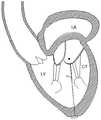
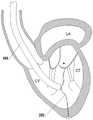
二尖瓣为左心房(图1、图2中由LA标示)和左心室(图1、图2中由LV标示)之间的单向“阀门”,可以保证血液从左心房流向左心室。二尖瓣关闭不全是当今最常见的心脏瓣膜疾病之一,主要是由于风湿性心脏病、二尖瓣粘液样变性、心脏缺血性疾病、心肌病变等引起二尖瓣结构中瓣环、瓣叶、腱索(图1、图2中由CT标示)以及乳头肌发生病变,导致二尖瓣的瓣叶不能完全闭合,左心室收缩时,血流的冲力会使得瓣叶脱入左心房,造成血液反流。The mitral valve is a one-way "valve" between the left atrium (indicated by LA in Figures 1 and 2) and the left ventricle (indicated by LV in Figures 1 and 2), allowing blood to flow from the left atrium to the left ventricle. Mitral regurgitation is one of the most common heart valve diseases today, mainly due to rheumatic heart disease, mitral valve myxoid degeneration, cardiac ischemic disease, cardiomyopathy, etc. The leaflets, chordae tendineae (marked by CT in Figures 1 and 2), and papillary muscles develop lesions, resulting in the failure of the leaflets of the mitral valve to close completely. Causes blood reflux.
针对二尖瓣关闭不全,可通过微创介入手术治疗,主要的介入治疗方式有人工腱索植入术、二尖瓣瓣环成形术及二尖瓣缘对缘修复术等,其中,人工腱索植入术是在瓣叶上植入人工腱索,能够有效地治疗因腱索断裂、瓣叶脱垂等导致的二尖瓣关闭不全,同时又保持二尖瓣结构的生理完整性。For mitral valve insufficiency, minimally invasive interventional surgery can be used to treat it. The main interventional treatments include artificial chordae tendineae implantation, mitral valve annuloplasty and mitral valve edge-to-edge repair. Among them, artificial tendon Cord implantation is the implantation of artificial chordae tendineae on the valve leaflets, which can effectively treat mitral valve insufficiency caused by chordae tendineae rupture and valve leaflet prolapse, while maintaining the physiological integrity of the mitral valve structure.
如图1所示,作为人工腱索x的医用缝线的一侧锚定在瓣叶上,另一侧锚定在乳头肌、心室壁或心尖上;人工腱索x植入初期,当左心室收缩时,医用缝线张紧,以代替原生腱索牵拉二尖瓣瓣叶使其恢复到正常的关闭状态;但是,如图2所示,人工腱索x植入一段时间后,左心室的体积会随着时间的推移而逐渐收缩到正常水平,相对应的,人工腱索的松紧状态则由张紧逐步变为松弛,从而导致对瓣叶的牵拉作用相应减弱,继而再度发生二尖瓣反流的情况。为解决这个问题,现有技术条件下,可重复进行手术,以植入新的长度缩短的人工腱索。As shown in Figure 1, one side of the medical suture used as the artificial chordae tendinea x is anchored on the valve leaflet, and the other side is anchored on the papillary muscle, ventricular wall or the apex; When the ventricle contracts, medical sutures are tensioned to replace the native chordae tendineae to pull the mitral valve leaflets back to their normal closed state; however, as shown in Figure 2, after the artificial chordae tendineae x were implanted for a period of time, The volume of the ventricle will gradually shrink to a normal level over time. Correspondingly, the tightness of the artificial chordae tendineae will gradually change from tension to relaxation, resulting in a corresponding weakening of the pulling effect on the valve leaflets, and then reoccurs. A condition of mitral regurgitation. To solve this problem, under the existing technical conditions, the operation can be repeated to implant new artificial chordae tendineae with shortened length.
发明内容SUMMARY OF THE INVENTION
本申请的目的在于提供一种人工腱索调控装置以及人工腱索调控系统,能够实时地、自适应地对人工腱索的有效长度进行调控,减弱或者消除由于人工腱索植入后随时间增长而松弛所导致的二尖瓣或其它心脏瓣膜的再度反流,避免重复手术。The purpose of this application is to provide an artificial chord regulation device and an artificial chord regulation system, which can adjust the effective length of the artificial chord in real time and adaptively, and reduce or eliminate the increase of the artificial chord over time after implantation. Re-regurgitation of the mitral valve or other heart valves caused by relaxation avoids repeated surgery.
为实现上述目的,本发明第一方面提供了一种人工腱索调控装置,包括调控主体件及钩形件;In order to achieve the above object, a first aspect of the present invention provides an artificial chord regulation device, comprising a main body part for regulation and a hook part;
所述调控主体件为具有弹性的自膨件,其内部中空,其远端开放,且其远端的径向尺寸大于其近端的径向尺寸;The regulating main body is an elastic self-expanding piece, its interior is hollow, its distal end is open, and the radial dimension of its distal end is larger than that of its proximal end;
所述钩形件包括至少一个钩形结构,以用于钩取人工腱索;the hook-shaped member includes at least one hook-shaped structure for hooking the artificial chordae;
所述钩形件钩取人工腱索时,所述钩形件的所述钩形结构伸出所述调控主体件的远端;When the hook-shaped member hooks the artificial tendon chord, the hook-shaped structure of the hook-shaped member extends out of the distal end of the regulating main body;
所述钩形件钩取人工腱索后,所述钩形件收容于所述调控主体件内且与所述调控主体件固定连接,所述钩形件牵拉部分所述人工腱索进入所述调控主体件内,所述调控主体件的远端与所述人工腱索位于所述钩形件的两侧的部分相抵持。After the hook-shaped member hooks the artificial tendon chord, the hook-shaped member is accommodated in the regulating main body and is fixedly connected with the regulating main body, and the hook-shaped member pulls part of the artificial tendon cable into the regulating body. In the regulating main body, the distal end of the regulating main body abuts against the parts of the artificial chordae on both sides of the hook-shaped member.
为实现上述目的,本发明第二方面提供了一种人工腱索调控系统,包括:可调弯鞘、输送装置以及如前述人工腱索调控装置;所述人工腱索调控装置的近端与所述输送装置的远端可拆卸连接,且所述人工腱索调控装置与所述输送装置均活动穿装于所述可调弯鞘内。In order to achieve the above purpose, a second aspect of the present invention provides an artificial chord regulation system, comprising: an adjustable sheath, a delivery device, and the aforementioned artificial chord regulation device; the proximal end of the artificial chord regulation device is connected to the The distal end of the delivery device is detachably connected, and both the artificial chordae regulation device and the delivery device are movably worn in the adjustable sheath.
本发明与现有技术相比,至少具有以下有益效果:Compared with the prior art, the present invention at least has the following beneficial effects:
本发明的人工腱索调控装置以及人工腱索调控系统,设置有弹性自膨的调控主体件及用于钩取腱索的钩形件,操作时,首先驱动钩形件的钩形结构伸出调控主体件的远端,并利用钩形结构对人工腱索进行钩取,之后再次驱动钩形件,以使其收容于调控主体件内且与调控主体件固定连接,在此过程中,人工腱索的冗长部分将被钩形件牵拉、收拢进调控主体件内,而调控主体件的远端将与人工腱索位于钩形件的两侧的部分相抵持,使得人工腱索弯折,从而缩短人工腱索的有效长度,此时调控主体件将在人工腱索的张力作用下,在人工腱索所在的径向方向上向外扩张变形;随着时间的推移,调控主体件的弹性特性使其总是趋向于恢复初始形状,从而调控主体件能够跟随由于心室体积变化导致的人工腱索有效长度的变化而发生实时地、适应性的变形,促使进入调控主体件内的人工腱索的长度逐渐增大,以补偿人工腱索的有效长度的变化量,进一步缩短人工腱索的有效长度。即,本发明的技术方案能够对人工腱索的有效长度进行实时的自适应调节,以保证人工腱索始终处于张紧状态,减弱或者消除由于人工腱索植入后随时间增长而松弛所导致的心脏瓣膜的再度反流,避免重复手术。The artificial tendon chord regulating device and the artificial tendon chord regulating system of the present invention are provided with an elastic self-expanding regulating main body and a hook-shaped member for hooking the tendon chord. During operation, the hook-shaped structure of the hook-shaped member is first driven to extend The distal end of the main body is regulated, and the artificial tendon chord is hooked by using the hook-shaped structure, and then the hook-shaped member is driven again, so that it is accommodated in the main body of regulation and is fixedly connected with the main body of regulation. The lengthy part of the chordae tendineae will be pulled by the hook-shaped member and tucked into the regulating body member, and the distal end of the regulating body member will abut against the parts of the artificial chordae tendineae on both sides of the hook-shaped member, so that the artificial chordae tendineae are bent , thereby shortening the effective length of the artificial chordae. At this time, the main body of the regulation will expand and deform outwards in the radial direction where the artificial chord is located under the tension of the artificial chord; The elastic properties make it always tend to return to the original shape, so that the regulating body can follow the change of the effective length of the artificial chordae tendineae due to the change of the ventricular volume to undergo real-time and adaptive deformation, and promote the artificial tendon entering the regulating body. The length of the chord is gradually increased to compensate for the variation of the effective length of the artificial chord and further shorten the effective length of the artificial chord. That is, the technical solution of the present invention can make real-time self-adaptive adjustment to the effective length of the artificial chordae tendineae, so as to ensure that the artificial chordae tendineae are always in a state of tension, and reduce or eliminate the relaxation caused by the growth of the artificial chordae tendineae over time after implantation. re-regurgitation of the heart valve, avoiding repeat surgery.
附图说明Description of drawings
此处的附图被并入说明书中并构成本说明书的一部分,示出了符合本发明的实施例,并与说明书一起用于解释本发明的原理。The accompanying drawings, which are incorporated in and constitute a part of this specification, illustrate embodiments consistent with the invention and together with the description serve to explain the principles of the invention.
为了更清楚地说明本发明实施例或现有技术中的技术方案,下面将对实施例或现有技术描述中所需要使用的附图作简单地介绍,显而易见地,对于本领域普通技术人员而言,在不付出创造性劳动性的前提下,还可以根据这些附图获得其它的附图。In order to more clearly illustrate the embodiments of the present invention or the technical solutions in the prior art, the following briefly introduces the accompanying drawings that need to be used in the description of the embodiments or the prior art. In other words, on the premise of no creative labor, other drawings can also be obtained based on these drawings.
图1为人工腱索植入初期处于张紧状态的示意图。Fig. 1 is a schematic diagram of the artificial chordae tendineae in a tension state at the initial stage of implantation.
图2为人工腱索植入一段时间后处于松弛状态的示意图。Figure 2 is a schematic diagram of the artificial chordae tendineae in a relaxed state after implantation for a period of time.
图3为根据本申请一示例性实施方式示出的人工腱索调控装置的剖视图。FIG. 3 is a cross-sectional view of an artificial chord regulating device according to an exemplary embodiment of the present application.
图4为图3中A位置的局部放大图。FIG. 4 is a partial enlarged view of the position A in FIG. 3 .
图5为一个角度示出的本申请的人工腱索调控装置钩取人工腱索后的示意图。FIG. 5 is a schematic diagram showing the artificial chord regulating device of the present application after hooking the artificial chord, shown from an angle.
图6为一个角度示出的本申请的人工腱索调控装置钩取人工腱索后的剖视图。FIG. 6 is a cross-sectional view of the artificial chord regulating device of the present application after hooking the artificial chord, shown from an angle.
图7为本申请的人工腱索调控装置调节人工腱索有效长度时,调控主体件变化示意图。FIG. 7 is a schematic diagram of the change of the main body for regulating and controlling when the artificial tendon chord regulating device of the present application regulates the effective length of the artificial tendon chord.
图8为图5中的调控主体件去除第一包覆物的结构示意图。FIG. 8 is a schematic structural diagram of the regulating main body in FIG. 5 with the first coating removed.
图9为本申请的人工腱索调控装置中配接件的结构示意图。FIG. 9 is a schematic structural diagram of a fitting in the artificial chord regulating device of the present application.
图10为又一角度示出的本申请的人工腱索调控装置钩取人工腱索后的剖视图。FIG. 10 is a cross-sectional view of the artificial chord regulating device of the present application after hooking the artificial chord, shown from another angle.
图11为图10中B位置的局部放大图。FIG. 11 is a partial enlarged view of position B in FIG. 10 .
图12为本申请的人工腱索调控装置中锚固件的锚片弹出的结构示意图。12 is a schematic structural diagram of the ejection of the anchor piece of the anchor in the artificial chord regulating device of the present application.
图13为图12中的锚片被收拢的结构示意图。FIG. 13 is a schematic view of the structure of the anchor sheet in FIG. 12 being folded.
图14为根据本申请一示例性实施方式示出的人工腱索调控系统的剖视图。14 is a cross-sectional view of an artificial chordae regulation system according to an exemplary embodiment of the present application.
图15为根据本申请一示例性实施方式示出的输送装置的剖视图。15 is a cross-sectional view of a delivery device according to an exemplary embodiment of the present application.
图16为图14中的调控主体件从可调弯鞘远端伸出后的结构示意图。FIG. 16 is a schematic structural diagram of the regulating body in FIG. 14 after extending from the distal end of the adjustable sheath.
图17为根据本申请又一示例性实施方式示出的人工腱索调控装置的钩形件的结构示意图。Fig. 17 is a schematic structural diagram of a hook-shaped member of an artificial chord regulation device according to yet another exemplary embodiment of the present application.
图18为本申请的人工腱索调控系统进入心脏内的示意图。FIG. 18 is a schematic diagram of the artificial chordae regulation system of the present application entering the heart.
其中,附图标记说明如下:Among them, the reference numerals are described as follows:
人工腱索调控装置1000、调控主体件1100、弹性网1101、第一包覆物1103、钩形件1200、锁定结构1300、锚固件1310、锚片1311、配接件1320、卡接部1330、加固件1400、人工腱索2000、可调弯鞘3000、输送装置4000、第一输送件4100,第二输送件4200、中间管4300,连接件4400。Artificial tendon
具体实施方式Detailed ways
为使本申请实施例的目的、技术方案和优点更加清楚,下面将结合本申请实施例中的附图,对本申请实施例中的技术方案进行清楚、完整地描述,显然,所描述的实施例是本申请的一部分实施例,而不是全部的实施例。基于本申请中的实施例,本领域普通技术人员在没有做出创造性劳动的前提下所获得的所有其它实施例,都属于本申请保护的范围。In order to make the purposes, technical solutions and advantages of the embodiments of the present application clearer, the technical solutions in the embodiments of the present application will be described clearly and completely below with reference to the drawings in the embodiments of the present application. Obviously, the described embodiments It is a part of the embodiments of this application, but not all of the embodiments. Based on the embodiments in the present application, all other embodiments obtained by those of ordinary skill in the art without creative work shall fall within the protection scope of the present application.
需要理解的是,“前”、“后”、“上”、“下”、“左”、“右”、“纵”、“横”、“竖直”、“水平”、“顶”、“底”、“内”、“外”、“头”、“尾”等指示的方位或位置关系为基于附图所示的方位或位置关系、以特定的方位构造和操作,仅是为了便于描述本技术方案,而不是指示所指的装置或元件必须具有特定的方位,因此不能理解为对本发明的限制。It should be understood that "front", "rear", "up", "down", "left", "right", "vertical", "horizontal", "vertical", "horizontal", "top", The orientation or positional relationship indicated by "bottom", "inner", "outer", "head", "tail", etc. is based on the orientation or positional relationship shown in the drawings, constructed and operated in a specific orientation, only for convenience The technical solution is described instead of indicating that the indicated device or element must have a specific orientation, so it should not be construed as a limitation on the present invention.
还需要说明的是,除非另有明确的规定和限定,“安装”、“相连”、“连接”、“固定”、“设置”等术语应做广义理解,例如,可以是固定连接,也可以是可拆卸连接,或成一体;可以是直接相连,也可以通过中间媒介间接相连,可以是两个元件内部的连通或两个元件的相互作用关系。当一个元件被称为在另一元件“上”或“下”时,该元件能够“直接地”或“间接地”位于另一元件之上,或者也可能存在一个或更多个居间元件。对于本领域的普通技术人员而言,可以根据具体情况理解上述术语在本发明中的具体含义。It should also be noted that, unless otherwise expressly specified and limited, terms such as "installation", "connection", "connection", "fixation" and "setup" should be understood in a broad sense, for example, it may be a fixed connection, or a It is a detachable connection or an integral body; it can be directly connected or indirectly connected through an intermediate medium, and it can be the internal communication of two elements or the interaction relationship between the two elements. When an element is referred to as being "on" or "under" another element, it can be "directly" or "indirectly" on the other element, or one or more intervening elements may also be present. For those of ordinary skill in the art, the specific meanings of the above terms in the present invention can be understood according to specific situations.
在本发明的描述中,仍需要说明的是,近端是指器械或部件靠近操作者的一端,远端是指器械或部件远离操作者的一端;轴向是指平行于器械或部件的远端与近端中心连线的方向,径向是指垂直于轴向的方向,周向是指环绕轴向的方向。In the description of the present invention, it should be noted that the proximal end refers to the end of the instrument or component close to the operator, the distal end refers to the end of the instrument or component away from the operator; the axial direction refers to the distal end parallel to the instrument or component The direction of the line connecting the center of the end and the proximal end, the radial direction refers to the direction perpendicular to the axial direction, and the circumferential direction refers to the direction surrounding the axial direction.
为了解决现有技术中人工腱索2000的松紧状态无法根据左心室体积变化情况进行自适应调节的问题,如图3-图13所示,本发明第一方面公开了一种人工腱索调控装置1000,包括调控主体件1100及钩形件1200。In order to solve the problem that the elastic state of the
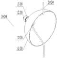
如图3、图5、图6与图8所示,调控主体件1100为具有弹性的自膨件,其内部中空,其远端开放,且其远端的径向尺寸大于其近端的径向尺寸,优选的,调控主体件1100的径向尺寸自其近端向其远端逐渐增大。具体的,调控主体件1100的整体形状可概呈碗形、锥筒形或喇叭形,以及其他满足本申请中调控主体件1100要求的其他形状,故本申请未对调控主体件1100的具体形状进行限定。As shown in FIG. 3 , FIG. 5 , FIG. 6 and FIG. 8 , the regulating
在一个具体的实施例中,如图3和图5所示,当调控主体件1100的整体形状概呈碗形时,调控主体件1100的母线相对于调控主体件1100的轴线呈向外凸起的弧形,该母线相对轴线旋转一周后即可大致形成碗形。In a specific embodiment, as shown in FIGS. 3 and 5 , when the overall shape of the regulating
为了保证调控主体件1100自身的弹性性能,根据本发明的一个实施例,如图3、图5和图8所示,调控主体件1100至少包括由形状记忆材料制作而成的弹性网1101。具体的,弹性网可以由形状记忆材料编织或切割而成,示例性的,可以采用由镍钛丝编织而成的弹性网,也可以采用镍钛管切割而成的网状结构,亦可是其他形状记忆材料,例如钴铬合金等,本实施例中采用镍钛丝编织定型而成。In order to ensure the elastic performance of the regulating
另外需要说明的是:调控主体件1100的远端的径向尺寸的范围为2.5mm-5mm,优选的,调控主体件1100远端的径向尺寸设置为3mm;调控主体件1100的近端的径向尺寸的范围为2mm-3mm;调控主体件1100的近端与远端的轴向距离优选1.5mm-4mm;其中,用于编织弹性网的镍钛丝的丝径范围为0.1mm-0.3mm,优选0.2mm,丝径太大或者太小都会影响弹性网在人工腱索2000作用下的变形程度及恢复初始形状的能力。以上尺寸的选定依据为:临床上人工腱索2000长期植入后的松弛量范围约为3mm-6mm,而且人工腱索2000对调控主体件1100的作用力应较小,介于1N-3N,按照以上尺寸范围编织而成的弹性网1101可以承受的作用力的数值范围为1N-5N,并且在该数值范围内作用力的作用下,弹性网1101具有良好的形变能力以及恢复至初始形状的回弹能力。In addition, it should be noted that the radial dimension of the distal end of the
钩形件1200包括至少一个钩形结构,至少一个钩形结构可以在调控主体件1100内进行360°转动,以用于钩取人工腱索2000。其中,在本申请的其中一个实施例中,如图3、图4、图10、图12和图13所示,钩形结构的数量设置为一个;为了更容易钩取人工腱索2000,减少钩形件1200转动,以节省钩取人工腱索2000的时间,在本申请的另一个实施例中,如图17所示,钩形结构的数量可设置为两个,两个钩形结构为对称设置;可以理解的是,在其他实施例中钩形结构的数量也可设置为两个以上,示例性的三个或者四个等,以提升对人工腱索2000钩取的便利性。具体的,钩形件1200选择生物相容性良好的刚性材料制作,例如SUS316L、PEEK等,钩形件1200的截面形状可为光滑的圆柱状以及其他方便钩取人工腱索2000的其他形状。The hook-shaped
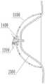
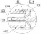
参照图3、图5、图6及图10,钩形件1200钩取人工腱索2000时,钩形件1200的钩形结构伸出调控主体件1100的远端;钩形件1200钩取人工腱索2000后,钩形件1200收容于调控主体件1100内且与调控主体件1100固定连接,钩形件1200牵拉部分人工腱索2000进入调控主体件1100内,调控主体件1100的远端与人工腱索2000位于钩形件1200的两侧的部分相抵持。3, 5, 6 and 10, when the hook-shaped
在上述实施例中,如图4所示,调控主体件1100的近端开放,钩形件1200钩取人工腱索2000前及钩形件1200钩取人工腱索2000时,钩形件1200的近端活动穿设于调控主体件1100的近端;钩形件1200钩取人工腱索2000后,钩形件1200的近端固定连接于调控主体件1100的近端,以保持将部分人工腱索2000收拢进调控主体件1100内。采用上述操作,结合图5,可以使得部分人工腱索2000弯折成“U”型或“几”型而收容于调控主体件1100内,从而有效缩短人工腱索2000的有效长度,并且通过调节钩形件1200的钩形结构相对调控主体件1100近端的距离,即可调节人工腱索2000在调控主体件1100内的弯折程度,从而实现对人工腱索2000的有效长度的初始调节,使得人工腱索2000的初始有效长度是合适的。应当说明的是,合适的人工腱索2000的有效长度应该是人工腱索2000能够牵拉瓣叶使得瓣叶可以正常闭合所需的长度。In the above embodiment, as shown in FIG. 4 , the proximal end of the regulating
具体操作过程如下:首先驱动钩形件1200的钩形结构伸出调控主体件1100的远端,并利用钩形结构对人工腱索2000进行钩取,之后再次驱动钩形件1200,以使其收容于调控主体件1100内且与调控主体件1100固定连接,在此过程中,部分人工腱索2000将被钩形件1200弯折后牵拉进入调控主体件1100内,而调控主体件1100的远端将与人工腱索2000位于钩形件1200的两侧的部分相抵持,此时如图7所示,调控主体件1100将在人工腱索2000的张力作用下,在人工腱索2000所在的径向方向上向外扩张变形。The specific operation process is as follows: first, the hook-shaped structure of the hook-shaped
随着时间的推移,心室体积逐渐减小,人工腱索2000有逐渐松弛的趋势,调控主体件1100自身的弹性特性促使调控主体件1100在自身回弹力的作用下逐渐发生趋于恢复初始形状的形变,在此过程中,调控主体件1100能够跟随由于心室体积变化导致的人工腱索2000有效长度的变化而发生实时地、适应性的变形,促使进入调控主体件1100内的人工腱索2000的长度逐渐增大,以补偿人工腱索2000的有效长度的变化量,进一步缩短人工腱索2000的有效长度。具体的,结合图7对上述调节过程进行解释:调控主体件1100在自身弹性力的作用下,从向外扩张位置A1回弹至位置A2的过程中,弧长并未变化,但钩形件1200与调控主体件1100远端边缘之间的弦长由B1增加到B2,即收容于调控主体件1100的人工腱索2000的长度增大。综上,本申请的人工腱索调控装置1000可以实现根据左心室体积变化情况,对人工腱索2000的有效长度进行实时地自适应调节,以保证人工腱索2000始终处于张紧状态,二尖瓣在心室收缩期能够保持闭合,有效避免出现腱索植入后的再度反流现象。With the passage of time, the volume of the ventricle gradually decreases, and the
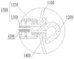
在上述实施例中,如图3、图4、图10以及图11所示,钩形件1200钩取人工腱索2000后,调控主体件1100的近端与钩形件1200的近端通过锁定结构1300固定连接。在本实施例中,锁定结构1300包括:相配合的锚固件1310和配接件1320。如图10、图11以及图12所示,锚固件1310包括若干个与钩形件1200的近端固定连接且向外翻翘的锚片1311,优选的,若干锚片1311在钩形件1200的近端的周向上间隔布置,多个锚片1311经由热定型处理后在自然状态下呈向外翻翘状。配接件1320套设于钩形件1200的近端外,且配接件1320的远端与调控主体件1100的近端固定连接。如图9-图11所示,配接件1320上设有若干卡接部1330,锚片1311与卡接部1330配合连接;优选的,若干卡接部1330在配接件1320的周向上间隔布置;卡接部1330为卡孔或卡槽。In the above embodiment, as shown in FIG. 3 , FIG. 4 , FIG. 10 and FIG. 11 , after the hook-shaped
具体的,钩形件1200钩取人工腱索2000后,锚固件1310的若干个锚片1311将一一对应插入设置于配接件1320上的卡孔内,从而实现调控主体件1100的近端与钩形件1200的近端稳定地固定连接,进而保持前述已做好初始调节的人工腱索2000的有效长度。Specifically, after the hook-shaped
应当知晓,此处的锁定结构1300仅用作举例,并不是对本申请的限制,本领域的普通技术人员基于本申请的启示,采用的其他锁定结构1300均在本申请的保护范围内。It should be known that the
根据本发明的一个实施例,结合图3、图5与图8,为了避免调控主体件1100对人工腱索2000造成损伤,调控主体件1100的远端部分包覆有第一包覆物1103,具体的,可以在整个弹性网1101上包覆第一包覆物1103,或者为了节省成本,仅在弹性网1101与人工腱索2000接触的远端包覆第一包覆物1103即可。第一包覆物可以采用具有生物相容性的柔性材质,在本实施例中,采用的是聚酯布。According to an embodiment of the present invention, referring to FIG. 3 , FIG. 5 and FIG. 8 , in order to avoid damage to the
钩形件1200的钩形结构上可包覆有第二包覆物(未图示),可以选用包覆聚酯布等织物或者覆硅胶膜来形成第二包覆物,从而减少在长期植入状态下,钩形结构对人工腱索2000的损伤。The hook-shaped structure of the hook-shaped
根据本发明的一个实施例,如图3与图4所示,调控主体件1100的近端与钩形件1200的近端之间还设有加固件1400。具体的,加固件1400内部中空,供钩形件1200的近端穿过,装配时,首先将调控主体件1100的近端焊接于配接件1320的远端,之后再将加固件1400的近端插入调控主体件1100的近端内,并通过焊接固定,上述设计,一方面可以增大调控主体件1100的连接稳定性,另一方面,可以增强调控主体件1100近端的抗形变能力;According to an embodiment of the present invention, as shown in FIG. 3 and FIG. 4 , a reinforcing
并且本实施例中,进一步将加固件1400的远端径向尺寸设计为大于近端径向尺寸,当钩形件1200钩取人工腱索2000后,钩形结构的开口的末端与加固件1400的远端贴合,或者与加固件1400的远端形成微小的间隙,其中,上述间隙小于人工腱索2000的直径,从而有效避免人工腱索2000从钩形结构内脱出。And in this embodiment, the radial dimension of the distal end of the reinforcing
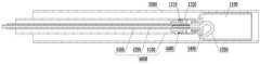
如图14-图16所示,结合图3、图4及图10至图13,本发明还公开了一种人工腱索调控系统,包括:可调弯鞘3000、输送装置4000以及前述人工腱索调控装置1000。人工腱索调控装置1000的近端与输送装置4000的远端可拆卸连接,且人工腱索调控装置1000与输送装置4000均活动穿装于可调弯鞘3000内。其中,可调弯鞘3000在现有技术中常见,通常包括调弯手柄及为可调弯的鞘管,通过调弯手柄可实现鞘管远端段的角度调弯,在此不做过多赘述。As shown in FIGS. 14-16 , in conjunction with FIGS. 3 , 4 and 10 to 13 , the present invention also discloses an artificial chord regulation system, including: an
具体的,如图14所示,由于调控主体件1100为具有弹性的自膨件,故在输送状态时,人工腱索调控装置1000的调控主体件1100将被收容于可调弯鞘3000的内腔,处于收拢状态,而当植入状态时,如图16所示,输送装置4000将驱动调控主体件1100伸出可调弯鞘3000的远端,此时,自膨件将在自身弹性力的作用下回弹至定型状态,之后通过输送装置4000驱动钩形件1200的钩形结构伸出调控主体件1100的远端,以钩取人工腱索2000;之后再次通过输送装置4000驱动钩形件1200,以使其收容于调控主体件1100内,在此过程中,部分人工腱索2000将被钩形件1200弯折后牵拉进入调控主体件1100内,而调控主体件1100的远端将与人工腱索2000位于钩形件1200的两侧的部分相抵持,从而实现对人工腱索2000的初始有效长度进行调节;接下来通过锁定结构1300将钩形件1200的近端与调控主体件1100进行锁定即可,以保持人工腱索2000的初始有效长度;最后只需将人工腱索调控装置1000的近端与输送装置4000的远端分离即可,并将输送装置4000撤回,而如图5所示的由钩形件1200、调控主体件1100、配接件1320、锚固件1310以及加固件1400构成的人工腱索调控装置1000留置于心室内,以对人工腱索2000的有效长度进行后续的实时自适应调节,以保证人工腱索2000始终处于张紧状态。Specifically, as shown in FIG. 14 , since the regulating
具体的,如图14和图15所示,输送装置4000包括:活动穿设于可调弯鞘3000内的第一输送件4100以及活动穿设于第一输送件4100内的第二输送件4200;第一输送件4100的远端与调控主体件1100的近端可拆卸连接,第二输送件4200的远端与钩形件1200的近端可拆卸连接;第一输送件4100用于驱动主体调控件伸出可调弯鞘3000的远端,第二输送件4200用于驱动钩形件1200相对主体调控件轴向运动及钩取人工腱索2000;植入完成后,首先将第一输送件4100与配接件1320分离,之后将第二输送件4200与钩形件1200的近端分离。Specifically, as shown in FIGS. 14 and 15 , the
在本实施例中,第一输送件4100和第二输送件4200均设置为中空管,其它实施例中的第二输送件4200还可以为杆;另外,本实施例中,如图14所示,可拆卸连接方式采用螺接,在其它实施例中还可以采用卡扣等。进一步的,如图15所示,第一输送件4100通过连接件4400与配接件1320可拆卸连接,其中,连接件4400的近端与第一输送件4100的远端固定连接,连接件4400的远端与配接件1320的近端通过螺纹连接,以实现第一输送件4100与调控主体件1100的可拆卸连接。In this embodiment, the first conveying
根据本发明的一个实施例,如图12、图13、图14以及图15所示,第一输送件4100与第二输送件4200之间活动套设有中间管4300,中间管4300用于控制钩形件1200由可相对主体调控件1100轴向运动的状态转变至与调控主体件1100固定连接的状态。具体的,如图3及图13所示,锚固件1310活动穿装于中间管4300内,中间管4300先对若干个锚片1311进行收拢和约束,此状态下,钩形件1200可以在第二输送件4200的驱动下,相对主体调控件1100进行轴向运动,以钩取人工腱索2000;如图11和图12所示,当钩形件1200已经钩取人工腱索2000且钩形件1200返回至相对调控主体件1100的初始位置后,向近端回撤中间管4300以解除对锚片1311的束缚,此时,若干个锚片1311将自动展开且一一对应弹入设置于配接件1320上的卡孔内,从而实现将调控主体件1100的近端与钩形件1200的近端固定连接在一起,进而实现保持前述已调节好的人工腱索2000的初始有效长度。According to an embodiment of the present invention, as shown in FIG. 12 , FIG. 13 , FIG. 14 and FIG. 15 , an
参照图18,以下对本申请的人工腱索调控系统对植入二尖瓣的人工腱索进行调控的使用过程进行说明:Referring to FIG. 18 , the following describes the use process of the artificial chordae tendineae regulating system of the present application for regulating the artificial chordae tendineae implanted in the mitral valve:
第一步:股动脉穿刺形成小切口后,将穿刺导丝(图未示出)经股动脉-腹主动脉-胸主动脉-主动脉弓送至左心室LV;The first step: after puncturing the femoral artery to form a small incision, the puncture guide wire (not shown) is sent to the left ventricle LV through the femoral artery-abdominal aorta-thoracic aorta-aortic arch;
第二步,将可调弯鞘3000沿穿刺导丝送入,直至可调弯鞘3000远端进入左心室LV,到达人工腱索2000附近,撤出穿刺导丝;In the second step, the
第三步,向近端后撤可调弯鞘3000或者同时向远端推送第一输送件4100、第二输送件4200及中间管4300,使得调控主体件1100伸出可调弯鞘3000的远端并展开成碗状形状;The third step is to withdraw the
第四步,同时向远端推送第二输送件4200及中间管4300,使得钩形件1200伸出调控主体件1100的远端,通过驱动第二输送件4200使得钩形件1200钩住人工腱索2000并回撤;The fourth step is to push the second conveying
第五步,向近端后撤中间管4300,若干个锚片1311弹入配接件1320的卡孔内,以实现钩形件1200与调控主体件1100的固定连接;In the fifth step, the
第六步,解除第一输送件4100与配接件1320的连接以及第二输送件4200与钩形件1200的连接,撤出第一输送件4100、中间管4300、第二输送件4200,完成人工腱索调控装置1000的植入。The sixth step is to release the connection between the first conveying
后续,随着时间的推移,如之前所述,人工腱索调控装置1000将对人工腱索2000的有效长度进行实时地、自适应地调节。Subsequently, over time, as described above, the artificial
以上仅是以调控植入二尖瓣的人工腱索为例,可以理解的是,本申请的人工腱索调控装置及人工腱索调控系统也可以对植入三尖瓣的人工腱索进行调控。The above is only an example of regulating the artificial chordae tendineae implanted in the mitral valve. It can be understood that the artificial chordae tendineae regulating device and the artificial chordae tendineae regulating system of the present application can also regulate the artificial chordae tendineae implanted in the tricuspid valve. .
以上仅是本发明的具体实施方式,使本领域技术人员能够理解或实现本发明。对这些实施例的多种修改对本领域的技术人员来说将是显而易见的,本文中所定义的一般原理可以在不脱离本发明的精神或范围的情况下,在其它实施例中实现。因此,本发明将不会被限制于本文所示的这些实施例,而是要符合与本文所申请的原理和新颖特点相一致的最宽的范围。The above are only specific embodiments of the present invention, so that those skilled in the art can understand or implement the present invention. Various modifications to these embodiments will be readily apparent to those skilled in the art, and the generic principles defined herein may be implemented in other embodiments without departing from the spirit or scope of the invention. Thus, the present invention is not intended to be limited to the embodiments shown herein, but is to be accorded the widest scope consistent with the principles and novel features claimed herein.
Claims (16)
Priority Applications (1)
| Application Number | Priority Date | Filing Date | Title |
|---|---|---|---|
| CN202011566110.6ACN114681124B (en) | 2020-12-25 | 2020-12-25 | Artificial tendon regulation device and artificial tendon regulation system |
Applications Claiming Priority (1)
| Application Number | Priority Date | Filing Date | Title |
|---|---|---|---|
| CN202011566110.6ACN114681124B (en) | 2020-12-25 | 2020-12-25 | Artificial tendon regulation device and artificial tendon regulation system |
Publications (2)
| Publication Number | Publication Date |
|---|---|
| CN114681124Atrue CN114681124A (en) | 2022-07-01 |
| CN114681124B CN114681124B (en) | 2025-07-11 |
Family
ID=82129341
Family Applications (1)
| Application Number | Title | Priority Date | Filing Date |
|---|---|---|---|
| CN202011566110.6AActiveCN114681124B (en) | 2020-12-25 | 2020-12-25 | Artificial tendon regulation device and artificial tendon regulation system |
Country Status (1)
| Country | Link |
|---|---|
| CN (1) | CN114681124B (en) |
Citations (5)
| Publication number | Priority date | Publication date | Assignee | Title |
|---|---|---|---|---|
| US20200155313A1 (en)* | 2017-11-07 | 2020-05-21 | Hangzhou Valgen Medtech Co., Ltd. | Artificial Chordae Tendineae Implantation System |
| US20200155315A1 (en)* | 2017-07-31 | 2020-05-21 | Hangzhou Valgen Medtech Co., Ltd. | Artificial chordae tendineae and artificial chordae tendineae implantation system |
| CN211934430U (en)* | 2019-12-31 | 2020-11-17 | 杭州德晋医疗科技有限公司 | Chordae tendineae regulating implant, chordae tendineae regulating device and chordae tendineae regulating system |
| CN212015867U (en)* | 2019-12-31 | 2020-11-27 | 杭州德晋医疗科技有限公司 | Minimally invasive artificial chordae tendineae adjusting system |
| CN215384904U (en)* | 2020-12-25 | 2022-01-04 | 杭州德晋医疗科技有限公司 | Artificial chordae tendineae regulating and controlling device and artificial chordae tendineae regulating and controlling system |
- 2020
- 2020-12-25CNCN202011566110.6Apatent/CN114681124B/enactiveActive
Patent Citations (5)
| Publication number | Priority date | Publication date | Assignee | Title |
|---|---|---|---|---|
| US20200155315A1 (en)* | 2017-07-31 | 2020-05-21 | Hangzhou Valgen Medtech Co., Ltd. | Artificial chordae tendineae and artificial chordae tendineae implantation system |
| US20200155313A1 (en)* | 2017-11-07 | 2020-05-21 | Hangzhou Valgen Medtech Co., Ltd. | Artificial Chordae Tendineae Implantation System |
| CN211934430U (en)* | 2019-12-31 | 2020-11-17 | 杭州德晋医疗科技有限公司 | Chordae tendineae regulating implant, chordae tendineae regulating device and chordae tendineae regulating system |
| CN212015867U (en)* | 2019-12-31 | 2020-11-27 | 杭州德晋医疗科技有限公司 | Minimally invasive artificial chordae tendineae adjusting system |
| CN215384904U (en)* | 2020-12-25 | 2022-01-04 | 杭州德晋医疗科技有限公司 | Artificial chordae tendineae regulating and controlling device and artificial chordae tendineae regulating and controlling system |
Also Published As
| Publication number | Publication date |
|---|---|
| CN114681124B (en) | 2025-07-11 |
Similar Documents
| Publication | Publication Date | Title |
|---|---|---|
| JP7340279B2 (en) | Devices, systems, and methods for reshaping heart valve annulus | |
| US20220054269A1 (en) | Device, system, and method for transcatheter treatment of valvular regurgitation | |
| US10456256B2 (en) | Heart valve repair | |
| US10449049B2 (en) | Prosthesis for preventing valve regurgitation | |
| JP2024503697A (en) | Heart valve sealing device and delivery device therefor | |
| JP5371440B2 (en) | Papillary muscle position control device, system and method | |
| JP2025078640A (en) | Axisymmetric adjustable device for treating mitral regurgitation | |
| CN102131479B (en) | Heart valve downsizing device and method | |
| WO2022006087A2 (en) | Systems and methods for heart valve leaflet repair | |
| CN110603007A (en) | Devices and methods for transcatheter mitral and tricuspid valve repair | |
| CN112912035A (en) | Implant for improving the coaptation of atrioventricular valves | |
| US20120179184A1 (en) | Heart valve remodeling | |
| WO2008067010A2 (en) | Method and apparatus for reshaping a ventricle | |
| CN115105265A (en) | A repair device that prevents mitral regurgitation | |
| WO2025039492A1 (en) | Valve prosthesis device having segmented tapered structure | |
| CN114376767A (en) | Annuloplasty device | |
| CN215384904U (en) | Artificial chordae tendineae regulating and controlling device and artificial chordae tendineae regulating and controlling system | |
| CN114681124A (en) | Artificial chordae tendineae regulating and controlling device and artificial chordae tendineae regulating and controlling system | |
| TWI893153B (en) | Systems for heart valve leaflet repair | |
| US20250302624A1 (en) | Leaflet augmenter | |
| US20250090313A1 (en) | Prosthetic valve device with a segmented tapered structure | |
| BR122024013415A2 (en) | SYSTEM FOR USE WITHIN A HEART VALVE FOR THE TREATMENT OF A LEAFLET | |
| BR122024013420A2 (en) | SYSTEM FOR USE WITH A VALVE OF A HEART OF A SINGLE INDIVIDUAL | |
| TW202224648A (en) | Systems and methods for heart valve leaflet repair | |
| CN104582637A (en) | Devices, systems and methods for transcatheter treatment of valvular regurgitation |
Legal Events
| Date | Code | Title | Description |
|---|---|---|---|
| PB01 | Publication | ||
| PB01 | Publication | ||
| SE01 | Entry into force of request for substantive examination | ||
| SE01 | Entry into force of request for substantive examination | ||
| GR01 | Patent grant | ||
| GR01 | Patent grant |