CN114680376A - Atomizer and electronic atomization device - Google Patents
Atomizer and electronic atomization deviceDownload PDFInfo
- Publication number
- CN114680376A CN114680376ACN202011557169.9ACN202011557169ACN114680376ACN 114680376 ACN114680376 ACN 114680376ACN 202011557169 ACN202011557169 ACN 202011557169ACN 114680376 ACN114680376 ACN 114680376A
- Authority
- CN
- China
- Prior art keywords
- liquid
- atomizer
- pump
- fluid
- nebulizer
- Prior art date
- Legal status (The legal status is an assumption and is not a legal conclusion. Google has not performed a legal analysis and makes no representation as to the accuracy of the status listed.)
- Pending
Links
Images


Classifications
- A—HUMAN NECESSITIES
- A24—TOBACCO; CIGARS; CIGARETTES; SIMULATED SMOKING DEVICES; SMOKERS' REQUISITES
- A24F—SMOKERS' REQUISITES; MATCH BOXES; SIMULATED SMOKING DEVICES
- A24F40/00—Electrically operated smoking devices; Component parts thereof; Manufacture thereof; Maintenance or testing thereof; Charging means specially adapted therefor
- A24F40/10—Devices using liquid inhalable precursors
- A—HUMAN NECESSITIES
- A24—TOBACCO; CIGARS; CIGARETTES; SIMULATED SMOKING DEVICES; SMOKERS' REQUISITES
- A24F—SMOKERS' REQUISITES; MATCH BOXES; SIMULATED SMOKING DEVICES
- A24F40/00—Electrically operated smoking devices; Component parts thereof; Manufacture thereof; Maintenance or testing thereof; Charging means specially adapted therefor
- A24F40/40—Constructional details, e.g. connection of cartridges and battery parts
Landscapes
- Special Spraying Apparatus (AREA)
Abstract
Description
Translated fromChinese技术领域technical field
本申请实施例涉及气溶胶生成系统技术领域,尤其涉及一种雾化器及电子雾化装置。The embodiments of the present application relate to the technical field of aerosol generation systems, and in particular, to an atomizer and an electronic atomization device.
背景技术Background technique
烟制品(例如,香烟、雪茄等)在使用过程中燃烧烟草以产生烟草烟雾。人们试图通过制造在不燃烧的情况下释放化合物的产品来替代这些燃烧烟草的制品。Smoking articles (eg, cigarettes, cigars, etc.) burn tobacco during use to produce tobacco smoke. Attempts have been made to replace these tobacco-burning products by making products that release compounds without burning them.
此类产品的示例为加热装置,其通过加热而不是燃烧材料来释放化合物。例如,该材料可为烟草或其他非烟草产品,这些非烟草产品可包含或可不包含尼古丁。作为另一示例,存在有气溶胶提供制品,例如,所谓的电子雾化装置。这些装置通常包含液体,该液体被加热以使其发生汽化,从而产生可吸入蒸气或气溶胶。已知的电子雾化装置中采用液体泵向加热器传递液体,液体泵在非工作时仍然有少量的液体渗流向加热器,影响通过液体泵供应给加热器的液体的量的准确性。An example of such a product is a heating device that releases a compound by heating rather than burning a material. For example, the material may be tobacco or other non-tobacco products, which may or may not contain nicotine. As another example, there are aerosol-providing articles, such as so-called electronic atomizing devices. These devices typically contain a liquid that is heated to vaporize it, resulting in a breathable vapor or aerosol. In the known electronic atomization device, a liquid pump is used to transfer liquid to the heater. When the liquid pump is not working, a small amount of liquid seeps to the heater, which affects the accuracy of the amount of liquid supplied to the heater by the liquid pump.
发明内容SUMMARY OF THE INVENTION
本申请实施例提供一种雾化器,被配置为雾化液体基质生成气溶胶;包括:The embodiment of the present application provides an atomizer, which is configured to atomize a liquid substrate to generate an aerosol; including:
储液腔,用于存储液体基质;Liquid storage chamber for storing liquid matrix;
雾化组件,用于雾化液体基质生成气溶胶;Atomization components for atomizing liquid substrates to generate aerosols;
液体泵,被配置为从所述储液腔吸取液体基质,并将吸取的液体基质供应至所述雾化组件;a liquid pump configured to draw a liquid substrate from the liquid storage chamber and supply the drawn liquid substrate to the atomizing assembly;
流体阀,定位于所述液体泵与雾化组件之间,被配置为选择性地导通或关闭所述液体泵与雾化组件之间的液体通道。A fluid valve, positioned between the liquid pump and the atomization assembly, is configured to selectively open or close the liquid passage between the liquid pump and the atomization assembly.
以上雾化器,通过流体阀可以在液体泵非使用时关闭液体基质在液体泵与雾化组件之间的流动,进而使通过液体泵提供给雾化组件的液体基质的量更加准确。In the above atomizer, the fluid valve can close the flow of the liquid matrix between the liquid pump and the atomizing assembly when the liquid pump is not in use, thereby making the amount of the liquid substrate supplied to the atomizing assembly by the liquid pump more accurate.
在优选的实施中,所述流体阀被配置为根据所述液体泵的启动导通所述液体泵与雾化组件之间的液体通道。In a preferred implementation, the fluid valve is configured to open the fluid passage between the fluid pump and the atomizing assembly upon activation of the fluid pump.
在优选的实施中,所述流体阀被配置为根据用户的抽吸动作导通所述液体泵与雾化组件之间的液体通道。In a preferred implementation, the fluid valve is configured to open the fluid passage between the fluid pump and the atomizing assembly in accordance with a user's pumping action.
在优选的实施中,所述液体泵具有向所述雾化组件供应液体基质的液体出口端;In a preferred implementation, the liquid pump has a liquid outlet port for supplying a liquid substrate to the atomizing assembly;
所述流体阀被配置为根据所述液体出口端的压力变化以导通所述液体泵与雾化组件之间的液体通道。The fluid valve is configured to open a fluid passage between the fluid pump and the atomizing assembly in response to pressure changes at the fluid outlet end.
在优选的实施中,所述流体阀包括关闭所述液体泵与雾化组件的液体通道的柔性的阀门部分,该阀门部分被构造成能响应所述液体出口端的压力变化产生形变,进而导通所述液体泵与雾化组件之间的液体通道。In a preferred implementation, the fluid valve includes a flexible valve portion that closes the liquid channel of the liquid pump and the atomizing assembly, and the valve portion is configured to deform in response to a pressure change at the liquid outlet end, thereby conducting conduction. The liquid channel between the liquid pump and the atomizing assembly.
在优选的实施中,所述阀门部分上设置有在产生形变时扩大的切口或狭缝或孔。In a preferred implementation, the valve portion is provided with cuts or slits or holes that expand upon deformation.
在优选的实施中,所述流体阀包括结合至所述液体出口端的保持部分,并通过该保持部分使所述流体阀保持在于所述液体出口端。In a preferred implementation, the fluid valve includes a retaining portion coupled to the liquid outlet end and by which the fluid valve is retained at the liquid outlet end.
在优选的实施中,所述保持部分被构造成至少部分围绕所述液体出口端。In a preferred implementation, the retaining portion is configured to at least partially surround the liquid outlet end.
在优选的实施中,所述液体泵包括可振动的压电陶瓷。In a preferred implementation, the liquid pump comprises a vibrating piezoelectric ceramic.
在优选的实施中,还包括:In a preferred implementation, it also includes:
壁,被配置为界定所述储液腔;所述壁的至少部分是柔性的。a wall configured to define the reservoir; at least a portion of the wall is flexible.
在优选的实施中,所述壁的柔性部分外侧的气压被保持与大气压相同。In a preferred implementation, the air pressure outside the flexible portion of the wall is kept the same as atmospheric pressure.
在优选的实施中,还包括:吸嘴盖,被构造成围绕所述壁的柔性部分;所述吸嘴盖毗邻所述壁的柔性部分的内表面上设有气槽,所述壁的柔性部分的外侧通过该气槽与大气保持连通。In a preferred implementation, it further comprises: a nozzle cover configured to surround the flexible portion of the wall; an air groove is provided on the inner surface of the nozzle cover adjacent to the flexible portion of the wall, the flexible portion of the wall is The outside of the part is kept in communication with the atmosphere through this air groove.
在优选的实施中,所述雾化组件包括:In a preferred implementation, the atomizing assembly includes:
刚性的多孔体,具有沿该多孔体的长度方向贯穿该多孔体的通道;a rigid porous body having channels extending through the porous body along its length;
柔性的导液纤维,被布置成位于所述通道内,并被构造成接收所述液体泵供应的液体基质;a flexible fluid-conducting fiber disposed within the channel and configured to receive a fluid matrix supplied by the fluid pump;
加热元件,结合于所述多孔体上,并用于加热所述多孔体的至少部分液体基质生成气溶胶。A heating element is attached to the porous body and used to heat at least a portion of the liquid matrix of the porous body to generate an aerosol.
在优选的实施中,还包括:In a preferred implementation, it also includes:
支架,被构造成保持所述液体泵和雾化组件。A stand configured to hold the liquid pump and atomizing assembly.
在优选的实施中,所述支架具有沿所述雾化器的纵向方向相背的第一端和第二端;In a preferred implementation, the bracket has a first end and a second end opposite in the longitudinal direction of the nebulizer;
所述支架设有由所述第一端贯穿至第二端的烟气输出通道,用于至少部分提供输出气溶胶的气流路径。The bracket is provided with a flue gas output channel penetrating from the first end to the second end for at least partially providing an air flow path for the output aerosol.
在优选的实施中,所述第一端比所述第二端更靠近所述储液腔;所述支架设有靠近所述第一端的第一保持空间、以及靠近所述第二端的第二保持空间;其中,所述液体泵被保持于所述第一保持空间,所述雾化组件被保持于所述第二保持空间;In a preferred implementation, the first end is closer to the liquid storage chamber than the second end; the bracket is provided with a first holding space close to the first end, and a first holding space close to the second end Two holding spaces; wherein, the liquid pump is held in the first holding space, and the atomizing assembly is held in the second holding space;
所述第一保持空间和第二保持空间被构造成位于所述烟气输出通道的同一侧。The first holding space and the second holding space are configured to be located on the same side of the flue gas output channel.
在优选的实施中,还包括:用于为所述雾化组件供电的第一电触头,以及为所述液体泵供电的第二电触头。In a preferred implementation, it further comprises: a first electrical contact for powering the atomizing assembly, and a second electrical contact for powering the liquid pump.
在优选的实施中,还包括:In a preferred implementation, it also includes:
电触头,用于为所述雾化器供电;electrical contacts for powering the atomizer;
电路板,被配置为在所述电触头与所述液体泵之间引导电流。A circuit board configured to conduct electrical current between the electrical contacts and the liquid pump.
在优选的实施中,所述液体泵偏离所述雾化器的中心轴线布置。In a preferred implementation, the liquid pump is arranged offset from the central axis of the atomizer.
本申请的又一个实施例还提出一种雾化器,被配置为雾化液体基质生成气溶胶;包括:Yet another embodiment of the present application also provides an atomizer configured to atomize a liquid substrate to generate an aerosol; including:
储液腔,用于存储液体基质;Liquid storage chamber for storing liquid matrix;
雾化组件,用于雾化液体基质生成气溶胶;Atomization components for atomizing liquid substrates to generate aerosols;
液体泵,被配置为从所述储液腔吸取液体基质,并将吸取的液体基质供应至所述雾化组件;a liquid pump configured to draw a liquid substrate from the liquid storage chamber and supply the drawn liquid substrate to the atomizing assembly;
支架,被构造成保持所述液体泵和雾化组件。A stand configured to hold the liquid pump and atomizing assembly.
在优选的实施中,所述支架具有沿所述雾化器的纵向方向相背的第一端和第二端,所述第一端比所述第二端更靠近所述储液腔;所述支架设有靠近所述第一端的第一保持空间、以及靠近所述第二端的第二保持空间;其中,所述液体泵被保持于所述第一保持空间,所述雾化组件被保持于所述第二保持空间;In a preferred implementation, the bracket has a first end and a second end opposite to each other in the longitudinal direction of the atomizer, the first end being closer to the liquid storage chamber than the second end; the The bracket is provided with a first holding space near the first end and a second holding space near the second end; wherein, the liquid pump is held in the first holding space, and the atomizing assembly is maintained in the second holding space;
所述雾化器内还设有沿毗邻所述第二保持空间边缘的收集腔,用于收集从所述第一保持空间渗出的液体基质。The atomizer is also provided with a collection cavity along the edge adjacent to the second holding space for collecting the liquid matrix seeping out from the first holding space.
本申请的又一个实施例还提出一种电子雾化装置,包括雾化液体基质生成气溶胶的雾化器、以及为所述雾化器供电的电源机构;所述雾化器包括以上所述的雾化器。Yet another embodiment of the present application also provides an electronic atomization device, comprising an atomizer for atomizing a liquid substrate to generate aerosol, and a power supply mechanism for supplying power to the atomizer; the atomizer includes the above-mentioned atomizer.
附图说明Description of drawings
一个或多个实施例通过与之对应的附图中的图片进行示例性说明,这些示例性说明并不构成对实施例的限定,附图中具有相同参考数字标号的元件表示为类似的元件,除非有特别申明,附图中的图不构成比例限制。One or more embodiments are exemplified by the pictures in the corresponding drawings, and these exemplifications do not constitute limitations of the embodiments, and elements with the same reference numerals in the drawings are denoted as similar elements, Unless otherwise stated, the figures in the accompanying drawings do not constitute a scale limitation.
图1是本申请一实施例提供的电子雾化装置的结构示意图;1 is a schematic structural diagram of an electronic atomization device provided by an embodiment of the present application;
图2是图1中雾化器从电源机构中移出状态的结构示意图;Fig. 2 is the structural representation of the state in which the atomizer is removed from the power supply mechanism in Fig. 1;
图3是图2中雾化器又一个视角下的结构示意图;Fig. 3 is the structural representation under another angle of view of the atomizer in Fig. 2;
图4是图3中雾化器一个视角下的吸嘴盖与内壳的分解示意图;FIG. 4 is an exploded schematic view of the nozzle cover and the inner shell from a viewing angle of the atomizer in FIG. 3;
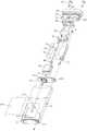
图5是图4中一个视角下内壳内各部件装配前的分解示意图;Fig. 5 is the exploded schematic diagram of each component in the inner shell from a viewing angle in Fig. 4 before assembly;
图6是图4中另一个视角下内壳内各部件装配前的分解示意图;Fig. 6 is the exploded schematic diagram of each component in the inner shell from another perspective in Fig. 4 before assembling;
图7是图5中电路板装配于端盖内的剖面示意图;FIG. 7 is a schematic cross-sectional view of the circuit board in FIG. 5 being assembled in the end cap;
图8是图5中内壳内各部件装配后的剖面示意图;FIG. 8 is a schematic cross-sectional view of each component in the inner casing in FIG. 5 after being assembled;
图9是图5中流体阀又一个视角下的结构示意图;FIG. 9 is a schematic structural diagram of the fluid valve in another perspective in FIG. 5;
图10是又一个实施例的流体阀的结构示意图;10 is a schematic structural diagram of a fluid valve according to another embodiment;
图11是又一个实施例的流体阀的结构示意图;11 is a schematic structural diagram of a fluid valve according to another embodiment;
图12是又一个实施例提供的雾化组件的结构示意图;12 is a schematic structural diagram of an atomizing assembly provided by another embodiment;
图13是又一个视角下吸嘴盖的结构示意图。FIG. 13 is a schematic structural diagram of the nozzle cover from another viewing angle.
具体实施方式Detailed ways
为了便于理解本申请,下面结合附图和具体实施方式,对本申请进行更详细的说明。In order to facilitate the understanding of the present application, the present application will be described in more detail below with reference to the accompanying drawings and specific embodiments.
本申请提出一种电子雾化装置,可以参见图1至图2所示,包括存储液体基质并对其雾化生成气溶胶的雾化器100、以及为雾化器100供电的电源机构200。The present application proposes an electronic atomization device, as shown in FIG. 1 to FIG. 2 , including an
电源机构200沿长度方向的下端设置有用于充电的充电接口210;电源机构200沿长度方向的上端设置有接收腔220;雾化器100的至少一部分可移除地接收和容纳在接收腔220内时与电源机构200的形成电连接。同时,雾化器100可以从接收腔220移出,以便于更换。The lower end of the
进一步雾化器100具有沿长度方向相对的近端110和远端120;在使用中,近端110作为用户嘴部抽吸使用的一端、远端120是接收于电源机构200的一端。雾化器100具有形成于近端110的吸嘴口A。Further, the
进一步参见图3所示,雾化器100包括:Referring further to Figure 3, the
外壳10,该外壳10靠近远端120的端部为敞口;the
端盖20,设置外壳10的敞口上以封闭外壳10;The
磁吸元件21,设置于端盖20上,用于当雾化器100至少部分接收于接收腔220内时与电源机构200磁性吸附,从而使雾化器100稳定保持在接收腔220内。The magnetic attracting
端盖20上还设置有进气口23,用于在抽吸中供外部空气进入至雾化器100内。The
端盖20上还设置有电连接孔22,当雾化器100至少部分接收于接收腔220内时,电源机构200的电极、电极弹针、供电的端子等可以通过该电连接孔22与雾化器100内部的电器部件形成电连接。The
图4示出了雾化器100的外壳10的分解示意图,外壳10包括:4 shows an exploded schematic view of the
内壳11,为透明材质;内部安装各功能部件,装配后它们部分可见;The
吸嘴盖12,覆盖内壳11的至少一部分,并可以从内壳11上移除;采用不透明的材质制备;安装中通过内壳11外壁上的卡凸111配合形成固定。吸嘴盖12靠近吸嘴口A的至少部分表面呈凹陷121的构造,便于用户抽吸中嘴唇的接触。The
同时,内壳11表面上设置有沿长度方向延伸的凸棱112,吸嘴盖12上配合设置有沿长度防线延伸的缺口122,由凸棱112和缺口122配合在结合和移除的过程中提供引导和定位。At the same time, the surface of the
内壳11靠近近端110的端部设置有注液孔15,用于向内壳11内的液体基质存储的部件进行注液。内壳11靠近近端110的端部还设置有气溶胶输出孔14,由该气溶胶输出孔14输出内部生成的气溶胶。The end of the
在内壳11靠近近端110的端部设置有柔性的第一密封元件13,该第一密封元件13具有沿朝注液孔15延伸出的密封部分131,用于密封注液孔15;第一密封元件13还设置有与气溶胶输出孔14相对的气孔132,以保证气溶胶的顺畅输出。A flexible first sealing element 13 is provided at the end of the
进一步参见图5至图7示,内壳11内包括:Further referring to FIGS. 5 to 7 , the
由内壳11内靠近上端的一部分空间界定的储液腔113,用于存储液体基质,并且是与注液孔15连通的,在使用中可以通过注液孔15对储液腔113进行注液。同时,储液腔113背离注液孔15的另一侧具有出液孔1131,储液腔113内的液体基质由该出液孔1131离开储液腔113。The
根据图5所示的优选实施,内壳11界定的储液腔113是具有沿厚度方向一侧的敞口的,进而由柔性密封膜114对储液腔113的敞口进行密封,形成完成的储液空间。并且在储液腔113内的液体基质消耗中,通过柔性密封膜114的柔性产生形变,收缩储液腔113的空间,进而消除或缓解内部的负压。According to the preferred implementation shown in FIG. 5 , the
在一个可选的实施中,柔性密封膜114采用弹性体橡胶材质制备,例如TPU材质(Thermoplastic polyurethanes,热塑性聚氨酯弹性体橡胶)等。在可选的实施中,柔性密封膜114是通过胶水与内壳11粘结的;或者在其他的可选实施中,柔性密封膜114是通过焊接结合的。In an optional implementation, the
由内壳11内靠近下端的部分空间界定的容纳腔116,容纳腔116用于安装各雾化功能相关的器件。当然,容纳腔116与储液腔113是设置有第二密封元件117,用于对储液腔113的液体基质流向容纳腔116的路径之外的缝隙进行密封。An
内壳11内还包括:雾化组件60,包括导液元件61、以及结合在导液元件61上的加热元件62;其中导液元件61通过毛细浸润吸收有储液腔113传递的液体基质,加热元件62用于对导液元件61内的至少部分液体基质加热生成供吸食的气溶胶。导液元件61可以采用或包括多孔陶瓷体、纤维棉、纤维绳、多孔材料等等;加热元件62可以采用电阻性的金属材料,例如铁、镍、铬或它们的合金等等。在图5至图7的优选实施例中,导液元件61是申请人在201920645593.5号专利中提出的具有横向贯穿的液体通道的多孔陶瓷体、或者是常用的上表面具有凹槽的杯状陶瓷。装配中同样是由上支架50容纳和保持,并向多孔陶瓷体传递液体基质。或者在其他的常规实施中,雾化组件60包括导液的柔性棉纤维、以及结合在棉纤维上的发热丝线圈等。The
进一步内壳11内还包括:液体泵30,该液体泵30定位于雾化组件60与储液腔113之间,并是与雾化组件60和储液腔113均是流体连通的,进而被构造成从储液腔113吸出液体基质并传递至雾化组件60,进而呈现如图5至图8中箭头R1所示的液体基质的传递路径。根据图5和图8所示,液体泵30具有入口端31和出口端32;其中,入口端31与储液腔113流体连通具体是与储液腔113的出液孔1131连通、出口端32与雾化组件60流体连通。Further, the
在可选的实施中,液体泵30采用的是包括可振动的压电陶瓷片的微型压电液泵(例如常州市易威奇公司出品的PSS7-B型微型计量液泵),通过可振动的压电陶瓷片的往复振动进而吸取和泵出液体基质;或者在其他的可选实施中,液体泵30还可以采用以隔膜膨胀和收缩的振动隔膜泵等等。In an optional implementation, the
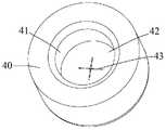
进一步参见图5和图9所示,液体泵30的出口端32设置有流体阀40,该流体阀40用于选择性的打开液体泵30的出口端32;当然在实施中,流体阀40是当液体泵30工作时打开出口端32,而在液体泵30非工作时该流体阀40是关闭的,以避免在非工作状态下储液腔113内的液体基质以液体泵30作为通道大量流出至雾化组件60,形成漏液。Further referring to FIG. 5 and FIG. 9 , the outlet end 32 of the
在图9所示的优选实施中,流体阀40是由柔性密封材料例如硅胶制备的,其结构包括:In the preferred implementation shown in FIG. 9, the
环形的保持部分41,围绕液体泵30的出口端32,进而便于流体阀40保持和安装在出口端32上;The
阀门部分42,位于保持部分41的一端,用于密封或关闭出口端32;a
切口或狭缝43,在图9中优选是交叉的十字型;进而当出口端32有液体基质泵出时,该切口或狭缝43可以使柔性材质的阀门部分42产生形变进而打开或者扩大切口或狭缝43,使泵出的液体基质传递至雾化组件60。当然,在液体泵30非工作时,切口或狭缝43是收拢的,进而可以阻止出口端32朝雾化组件60渗出液体。进而在实施中,流体阀40主要是阀门部分42是响应于液体泵30的出口端32的压力变化,进而打开液体基质的传递通路;具体当出口端32有液体基质泵出时,则泵出液体基质的过程中使阀门部分42靠近出口端32一侧的压力增大,进而冲开切口或狭缝43。The incision or slit 43 is preferably a cross-shaped cross in FIG. 9; and when the liquid substrate is pumped out of the
在其他的可选实施中,流体阀40还可以是电控式的阀门。In other optional implementations, the
或者在其他的可选实施中,流体阀40是通过监测液体泵30的启动进而打开液体基质的传递通路;通常如果液体泵30的启动是根据用户的抽吸来控制的,则流体阀40可以根据监测的用户的抽吸动作进而打开液体基质的传递通路。在可选的实施中,用户的抽吸动作是由电源机构200内设置的气流传感器监测的。Or in other alternative implementations, the
或者图10示出了又一个实施例的流体阀40a的示意图,阀门部分42a设置有若干微米级的筛孔43a,筛孔43a的孔径0.3~0.8mm;则当液体泵30非工作时,由液体泵30的出口端32渗流出的液体基质由于毛细张力形成弯月面或液膜,进而不会继续渗漏;当液体泵30工作时产生的压力能冲开液膜或破坏弯月面,从而导通流体阀40a。Or FIG. 10 shows a schematic diagram of a
或者图11示出了又一个实施例的流体阀40b的示意图,阀门部分42a上设置有U形的切口或狭缝43b,并由该U形的切口或狭缝43b界定位于U形的切口或狭缝43b内的可活动的部分431b;当液体泵30泵出液体基质时产生的压力能使可活动的部分431b朝外翘起或活动,进而扩大U形的切口或狭缝43b使液体基质能流向雾化组件。在液体泵30非工作时,可活动的部分431b回复至图11所示的状态以阻止非使用状态的液体基质渗出。Alternatively, FIG. 11 shows a schematic diagram of a
为了便于雾化组件60和液体泵30在内壳11内的安装和固定,内壳11的容纳腔116内设置有支架50;该支架50设置有:In order to facilitate the installation and fixation of the atomizing
第一安装空间51,靠近储液腔113,用于容纳和保持液体泵30;The
第二安装空间52,靠近端盖20,用于容纳和保持雾化组件60;The
其中,在布置的方式上第一安装空间51是偏离支架50的中心轴线的,并且沿纵向方向第一安装空间51和第二安装空间52至少部分是相对偏置的,则在装配后液体泵30的出口端32是朝着或对着雾化组件60一端的。装配后,第一安装空间51或液体泵30是偏离雾化器100的中心轴线的。Wherein, in the way of arrangement, the
支架50与雾化组件60之间,具体是在第二安装空间52的内壁与雾化组件60之间设置有第三密封元件70,用于对第二安装空间52与雾化组件60之间的间隙进行密封。A
支架50上设置有沿纵向方向贯穿的烟气通道53,用于将雾化组件60生成的气溶胶输出至气溶胶输出孔14。根据图5至图8中所示,烟气通道53是靠近支架50沿宽度方向的其中一侧布置的;则布置上第一安装空间51和第二安装空间52是位于烟气通道53的同一侧的。The
进一步在图5和图7所示的优选实施中,雾化组件60的导液元件61具有朝端盖20的雾化面,加热元件62形成于雾化面上。在抽吸过程中的气流路径上,参见图5至图8中箭头R2所示,外部空气由端盖20上的进气口23进入雾化组件60与端盖20之间,而后由导液元件61雾化面的一侧流经另一侧携带生成的气溶胶由支架50的烟气通道53输出至气溶胶输出孔14。Further in the preferred implementation shown in FIGS. 5 and 7 , the liquid-conducting
进一步为了便于对液体泵30和雾化组件60供电,内壳11内还设置有电路板80。该电路板80上设置有与端盖20上的电连接孔22相对的电触头82;进而使电源机构200的电极、电极弹针、供电的端子通过该电触头82对电连接在电路板80上的各雾化器100内的电器元件供电。Further, in order to facilitate power supply to the
例如,电路板80上具有延伸出的电极柱81,在实施中通过该电极柱与雾化组件60的加热元件62焊接或抵靠形成导通,进而在电源机构200与加热元件62之间引导电流。在又一个的可选的实施中,液体泵30是通过导线直接焊接在电路板80上实现供电的。For example, the
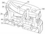
进一步为了对电路板80进行固定和保护,参见图7和图8所示,端盖20内部是具有中空的容纳空间的,端盖20具有位于远端120的盖板25,该盖板25是可拆卸或移除的以打开中空的容纳空间。电路板80是被容纳和保持在端盖20的容纳空间内的;并且端盖20上设置有朝支架50并且可以拆卸的保持元件24,该保持元件24将电路板80压紧或夹持等方式使其安装后稳定保持在端盖20内。In order to further fix and protect the
根据图6至图8所示的优选实施,保持元件24朝向雾化组件60的表面上毗邻雾化组件60的边缘的位置设置有收集槽241,用于收集和存储由雾化组件60的边缘渗流出的液体基质。According to the preferred implementation shown in FIGS. 6 to 8 , a collecting
同时,保持元件24位于电路板80与雾化组件60之间,进而可以用于承接气溶胶的冷凝液或者渗出的液体以避免它们渗流至电路板80上以保护电路板80。在优选的实施中,保持元件24朝向雾化组件60表面至少部分被构造成倾斜的弧形斜面242,用于引导抽吸中的气流。At the same time, the holding
进一步图12示出了又一个实施例示出的雾化组件60的示意图,包括刚性的多孔体61a和柔性的导液纤维63a;其中,Further, FIG. 12 shows a schematic diagram of the
多孔体61a,具有沿厚度方向相对的第一侧壁611a和第二侧壁612a,以及在第一侧壁611a和第二侧壁612a之间延伸的基体部分613a,进而由第一侧壁611a、第二侧壁612a和基体部分613a界定了沿长度方向贯穿多孔体61a的液体通道614a;导液纤维63a例如纤维棉是被容纳和保持在液体通道614a内的。采用具有刚性的多孔体61a和柔性的导液纤维63a的雾化组件60,对于安装和将液体基质准确地向雾化面上的加热元件62供应是有利的。并且在实施中,由液体泵30的出口端32是通过流体阀40对准导液纤维63a的,则在工作中由液体泵30的出口端32泵出的液体基质先由导液纤维63a吸收后,再传递至多孔体61a。The
图13示出了吸嘴盖12的又一个视角的示意图;吸嘴盖12毗邻柔性密封膜114的内壁上设置有沿纵向延伸并与大气连通的槽123。在储液腔113内的液体基质逐渐消耗使内部负压逐渐增大时,槽123能始终保证柔性密封膜114与吸嘴盖12的内壁之间具有间隙、而非与吸嘴盖12的内壁紧贴,能保证柔性密封膜114的外侧气压始终为大气压,进而能大于内侧气压促进柔性密封膜114能顺畅朝储液腔113内变形,以消除或缓解或平衡储液腔113的负压。FIG. 13 shows a schematic view of the suction nozzle cover 12 from another perspective; the inner wall of the
在以上实施中,当液体泵30工作时泵出的液体基质的速度小于雾化组件60雾化的速度时,雾化组件60将干烧;当液体泵30工作时泵出的液体基质的速度大于雾化组件60雾化的速度时,未雾化的多余的液体基质达到一定量时将溢出例如溢出至抽吸气流中。In the above implementation, when the speed of the liquid substrate pumped out by the
在一个优选的实施中,以加热元件62的电阻1.1欧姆、雾化功率6瓦、设计流量0.1ml/min、液体基质的密度ρ=1.15g/ml,液体胶基质的冷凝率0.15为例,理论计算在抽吸中TPM为5mg/口。对应以上实施,将液体泵30工作时泵出的液体基质的流速控制在0.30±0.02ml/min范围内,且液体泵30连续运行2小时,流速衰减小于0.02ml/min;确保液体泵30的供液流速与雾化速度平衡,防止出现液体基质外溢或干烧的现象。In a preferred implementation, the resistance of the
需要说明的是,本申请的说明书及其附图中给出了本申请的较佳的实施例,但并不限于本说明书所描述的实施例,进一步地,对本领域普通技术人员来说,可以根据上述说明加以改进或变换,而所有这些改进和变换都应属于本申请所附权利要求的保护范围。It should be noted that the description of the present application and the accompanying drawings provide preferred embodiments of the present application, but are not limited to the embodiments described in the present specification. Improvements or changes are made according to the above description, and all these improvements and changes should fall within the protection scope of the appended claims of the present application.
Claims (20)
Translated fromChinesePriority Applications (1)
| Application Number | Priority Date | Filing Date | Title |
|---|---|---|---|
| CN202011557169.9ACN114680376A (en) | 2020-12-25 | 2020-12-25 | Atomizer and electronic atomization device |
Applications Claiming Priority (1)
| Application Number | Priority Date | Filing Date | Title |
|---|---|---|---|
| CN202011557169.9ACN114680376A (en) | 2020-12-25 | 2020-12-25 | Atomizer and electronic atomization device |
Publications (1)
| Publication Number | Publication Date |
|---|---|
| CN114680376Atrue CN114680376A (en) | 2022-07-01 |
Family
ID=82130342
Family Applications (1)
| Application Number | Title | Priority Date | Filing Date |
|---|---|---|---|
| CN202011557169.9APendingCN114680376A (en) | 2020-12-25 | 2020-12-25 | Atomizer and electronic atomization device |
Country Status (1)
| Country | Link |
|---|---|
| CN (1) | CN114680376A (en) |
Cited By (1)
| Publication number | Priority date | Publication date | Assignee | Title |
|---|---|---|---|---|
| WO2025077549A1 (en)* | 2023-10-13 | 2025-04-17 | 深圳市合元科技有限公司 | Electronic atomization device |
Citations (15)
| Publication number | Priority date | Publication date | Assignee | Title |
|---|---|---|---|---|
| US20020195242A1 (en)* | 2001-06-20 | 2002-12-26 | Garner Scott D. | Porous vapor valve for improved loop thermosiphon performance |
| CN1518861A (en)* | 2003-01-23 | 2004-08-11 | 钧 诸 | Water control valve and pipe as well as application in micro irrigation technique for plant |
| CN105283088A (en)* | 2013-05-28 | 2016-01-27 | Sis资源有限公司 | One-way valve for cartomizer section of electronic cigarettes |
| CN107846970A (en)* | 2015-07-10 | 2018-03-27 | 菲利普莫里斯生产公司 | Aerosol-generating articles comprising liquid delivery elements |
| CN109832669A (en)* | 2017-11-29 | 2019-06-04 | 上海新型烟草制品研究院有限公司 | A kind of electronic cigarette leakproof oil fogger |
| CN110602956A (en)* | 2017-03-29 | 2019-12-20 | Jt国际股份公司 | Apparatus, system and method for generating aerosol |
| CN110623309A (en)* | 2019-10-09 | 2019-12-31 | 深圳格林韵达科技有限公司 | Anti-leakage oil one-way intake valve, electronic cigarette heating chamber components and electronic cigarette |
| CN110710718A (en)* | 2019-11-20 | 2020-01-21 | 常州市穆塞电气控制设备有限公司 | an electronic cigarette |
| CN210203317U (en)* | 2019-05-07 | 2020-03-31 | 深圳市合元科技有限公司 | Atomizer and electronic cigarette |
| CN210407103U (en)* | 2019-04-11 | 2020-04-28 | 深圳市康特客科技有限公司 | Electronic cigarette and atomization device thereof |
| CN111109677A (en)* | 2020-01-17 | 2020-05-08 | 深圳麦克韦尔科技有限公司 | Electronic atomization device and atomizer and atomization assembly thereof |
| CN111213917A (en)* | 2020-01-03 | 2020-06-02 | 深圳雪雾科技有限公司 | A flexible switch, electron cigarette bullet and electron cigarette for electron cigarette |
| CN111468197A (en)* | 2020-04-13 | 2020-07-31 | 长春理工大学 | Hydraulic-driven elastic diaphragm micro valve for centrifugal microfluidic system and preparation method thereof |
| CN211746967U (en)* | 2019-12-17 | 2020-10-27 | 深圳麦克韦尔科技有限公司 | Atomizer and electronic atomization device |
| CN211746945U (en)* | 2020-02-25 | 2020-10-27 | 常州市派腾电子技术服务有限公司 | Nebulizer and aerosol generating device |
- 2020
- 2020-12-25CNCN202011557169.9Apatent/CN114680376A/enactivePending
Patent Citations (15)
| Publication number | Priority date | Publication date | Assignee | Title |
|---|---|---|---|---|
| US20020195242A1 (en)* | 2001-06-20 | 2002-12-26 | Garner Scott D. | Porous vapor valve for improved loop thermosiphon performance |
| CN1518861A (en)* | 2003-01-23 | 2004-08-11 | 钧 诸 | Water control valve and pipe as well as application in micro irrigation technique for plant |
| CN105283088A (en)* | 2013-05-28 | 2016-01-27 | Sis资源有限公司 | One-way valve for cartomizer section of electronic cigarettes |
| CN107846970A (en)* | 2015-07-10 | 2018-03-27 | 菲利普莫里斯生产公司 | Aerosol-generating articles comprising liquid delivery elements |
| CN110602956A (en)* | 2017-03-29 | 2019-12-20 | Jt国际股份公司 | Apparatus, system and method for generating aerosol |
| CN109832669A (en)* | 2017-11-29 | 2019-06-04 | 上海新型烟草制品研究院有限公司 | A kind of electronic cigarette leakproof oil fogger |
| CN210407103U (en)* | 2019-04-11 | 2020-04-28 | 深圳市康特客科技有限公司 | Electronic cigarette and atomization device thereof |
| CN210203317U (en)* | 2019-05-07 | 2020-03-31 | 深圳市合元科技有限公司 | Atomizer and electronic cigarette |
| CN110623309A (en)* | 2019-10-09 | 2019-12-31 | 深圳格林韵达科技有限公司 | Anti-leakage oil one-way intake valve, electronic cigarette heating chamber components and electronic cigarette |
| CN110710718A (en)* | 2019-11-20 | 2020-01-21 | 常州市穆塞电气控制设备有限公司 | an electronic cigarette |
| CN211746967U (en)* | 2019-12-17 | 2020-10-27 | 深圳麦克韦尔科技有限公司 | Atomizer and electronic atomization device |
| CN111213917A (en)* | 2020-01-03 | 2020-06-02 | 深圳雪雾科技有限公司 | A flexible switch, electron cigarette bullet and electron cigarette for electron cigarette |
| CN111109677A (en)* | 2020-01-17 | 2020-05-08 | 深圳麦克韦尔科技有限公司 | Electronic atomization device and atomizer and atomization assembly thereof |
| CN211746945U (en)* | 2020-02-25 | 2020-10-27 | 常州市派腾电子技术服务有限公司 | Nebulizer and aerosol generating device |
| CN111468197A (en)* | 2020-04-13 | 2020-07-31 | 长春理工大学 | Hydraulic-driven elastic diaphragm micro valve for centrifugal microfluidic system and preparation method thereof |
Cited By (1)
| Publication number | Priority date | Publication date | Assignee | Title |
|---|---|---|---|---|
| WO2025077549A1 (en)* | 2023-10-13 | 2025-04-17 | 深圳市合元科技有限公司 | Electronic atomization device |
Similar Documents
| Publication | Publication Date | Title |
|---|---|---|
| JP7016395B2 (en) | Cartridges, battery units and e-cigarettes | |
| CN217446684U (en) | Electronic atomization device | |
| CN215347013U (en) | Atomizers and Electronic Atomizers | |
| CN212852492U (en) | Aerosol generating device and aerosol electronic inhaler | |
| CN215684777U (en) | Atomizers and Electronic Atomizers | |
| CN112273728A (en) | A power supply assembly and electronic atomization device | |
| CN115153093A (en) | Electronic atomization device | |
| CN218354595U (en) | Atomizer and electronic atomization device | |
| TW202126198A (en) | Electronic cigarette | |
| CN215684857U (en) | Atomizer and electronic atomization device | |
| CN222466045U (en) | Electronic atomizing device and liquid reservoir for same | |
| CN215958310U (en) | Atomizers and Electronic Atomizers | |
| CN214677559U (en) | Atomizing storehouse and atomizer | |
| CN114680376A (en) | Atomizer and electronic atomization device | |
| CN216983562U (en) | Atomizer and electronic atomization device | |
| CN215684856U (en) | Atomizer, electronic atomization device and sealing element for atomizer | |
| CN215347034U (en) | Atomizers and Electronic Atomizers | |
| CN222109288U (en) | Electronic atomization device and second body | |
| CN215347024U (en) | Atomizers and Electronic Atomizers | |
| CN214283306U (en) | Power supply module and electronic atomization device | |
| CN222109281U (en) | Electronic atomization device, device body and liquid source | |
| CN222303121U (en) | Atomizer and electronic atomization device | |
| CN218737218U (en) | Atomizer and electronic atomization device thereof | |
| CN216983599U (en) | Atomizers and Electronic Atomizers | |
| KR102845864B1 (en) | Aerosol generator having sealed air intake pass |
Legal Events
| Date | Code | Title | Description |
|---|---|---|---|
| PB01 | Publication | ||
| PB01 | Publication | ||
| SE01 | Entry into force of request for substantive examination | ||
| SE01 | Entry into force of request for substantive examination |