CN114674207A - Bottom surface flatness measuring device and method for flat-bottom blind hole - Google Patents
Bottom surface flatness measuring device and method for flat-bottom blind holeDownload PDFInfo
- Publication number
- CN114674207A CN114674207ACN202210460266.9ACN202210460266ACN114674207ACN 114674207 ACN114674207 ACN 114674207ACN 202210460266 ACN202210460266 ACN 202210460266ACN 114674207 ACN114674207 ACN 114674207A
- Authority
- CN
- China
- Prior art keywords
- measuring
- blind hole
- needle
- flatness
- flat
- Prior art date
- Legal status (The legal status is an assumption and is not a legal conclusion. Google has not performed a legal analysis and makes no representation as to the accuracy of the status listed.)
- Granted
Links
Images


Classifications
- G—PHYSICS
- G01—MEASURING; TESTING
- G01B—MEASURING LENGTH, THICKNESS OR SIMILAR LINEAR DIMENSIONS; MEASURING ANGLES; MEASURING AREAS; MEASURING IRREGULARITIES OF SURFACES OR CONTOURS
- G01B5/00—Measuring arrangements characterised by the use of mechanical techniques
- G01B5/28—Measuring arrangements characterised by the use of mechanical techniques for measuring roughness or irregularity of surfaces
- Y—GENERAL TAGGING OF NEW TECHNOLOGICAL DEVELOPMENTS; GENERAL TAGGING OF CROSS-SECTIONAL TECHNOLOGIES SPANNING OVER SEVERAL SECTIONS OF THE IPC; TECHNICAL SUBJECTS COVERED BY FORMER USPC CROSS-REFERENCE ART COLLECTIONS [XRACs] AND DIGESTS
- Y02—TECHNOLOGIES OR APPLICATIONS FOR MITIGATION OR ADAPTATION AGAINST CLIMATE CHANGE
- Y02E—REDUCTION OF GREENHOUSE GAS [GHG] EMISSIONS, RELATED TO ENERGY GENERATION, TRANSMISSION OR DISTRIBUTION
- Y02E30/00—Energy generation of nuclear origin
- Y02E30/30—Nuclear fission reactors
Landscapes
- Physics & Mathematics (AREA)
- General Physics & Mathematics (AREA)
- A Measuring Device Byusing Mechanical Method (AREA)
Abstract
Description
Translated fromChinese技术领域technical field
本发明属于盲孔测量技术领域,更具体地说,涉及一种平底盲孔的底面平面度测量装置和方法。The invention belongs to the technical field of blind hole measurement, and more particularly relates to a bottom surface flatness measurement device and method of a flat-bottom blind hole.
背景技术Background technique
盲孔是连接表层和内层而不贯通整板的导通孔。在生产加工中,各类盲孔类零件是较为常见的。其中,一些生产设备和工艺中对于一些所需的盲孔类零件的盲孔的精度具有较高的要求,目前,测量盲孔的几何量主要有盲孔深度和盲孔内径。但是,在一些特殊设备中,对于盲孔类零件的盲孔的底面平面度也有着较高的要求。Blind vias are vias that connect the surface layer and the inner layer without penetrating the entire board. In production and processing, various types of blind hole parts are more common. Among them, some production equipment and processes have high requirements for the accuracy of blind holes of some required blind holes. At present, the geometric quantities of blind holes are mainly blind hole depth and blind hole inner diameter. However, in some special equipment, there is also a high requirement for the flatness of the bottom surface of the blind hole of the blind hole type parts.
目前,一般采用塑形复制品法对平底盲孔的底面平面度进行测量,测量时向盲孔中浇注塑性材料将盲孔填充,待材料凝固成型后将孔内的复制品取出,通过对复制品的底面平面度进行测量来确定平底盲孔的底面平面度。但是,对于孔径小于2mm、深径比大于10的平底盲孔,注模时很难保证复制品的质量,容易出现复制品与盲孔底面不够贴合而导致复制品的底面平面度与盲孔底面平面度不一致的情况。同时,复制品从这种孔中取出非常困难,取出过程往往会使得复制品表面出现损伤,使得复制品难以完整地反映平底盲孔平面度的特征,导致对于孔径小于2mm、深径比大于10的平底盲孔的平面度测量十分困难。At present, the flatness of the bottom surface of flat-bottomed blind holes is generally measured by the plastic replica method. During the measurement, injection molding material is poured into the blind hole to fill the blind hole. After the material is solidified and formed, the replica in the hole is taken out. The bottom surface flatness of the product is measured to determine the bottom surface flatness of the flat-bottom blind hole. However, for flat-bottomed blind holes with a diameter of less than 2 mm and an aspect ratio greater than 10, it is difficult to ensure the quality of the replica during injection molding. Inconsistencies in the flatness of the bottom surface. At the same time, it is very difficult to remove the replica from such a hole, and the removal process often causes damage to the surface of the replica, making it difficult for the replica to fully reflect the flatness of the flat-bottomed blind hole. It is very difficult to measure the flatness of flat-bottomed blind holes.
现有技术中也存在一些平面度测量方法,例如激光和光纤测量方法,然而在实际使用时发现,这种测量方式对于孔径和孔深的测量结果较为精确,但是对于深径比大于10的微小平底盲孔,激光和光纤难以完整地照射至盲孔底部,测量结果不够精确。市面上其余的一些平面度测量设备也难以适用于这种孔径小于2mm、深径比大于10的平底盲孔的底面平面度的测量。There are also some flatness measurement methods in the prior art, such as laser and optical fiber measurement methods. However, in actual use, it is found that this measurement method is more accurate for the measurement results of the aperture and hole depth, but is more than 10. For flat-bottomed blind holes, it is difficult for lasers and optical fibers to completely irradiate the bottom of the blind holes, and the measurement results are not accurate enough. Some other flatness measurement equipments on the market are also difficult to apply to the measurement of the flatness of the bottom surface of the flat-bottom blind hole with a diameter of less than 2 mm and an aspect ratio of more than 10.
如中国专利申请号为:CN201610369045.5,公开日为:2016年8月10日的专利文献,公开了一种测平面度工装,包括平面底板,均垂直设置于平面底板上并分别位于平面底板两侧端的两立柱,横架于两立柱之间并与平面底板相平行设置的横杆,套装于横杆上可沿横杆滑移的滑块,以及设置于滑块侧面用于检测平面度的百分表;所述百分表包括依次相连的表体和测量杆,表体的背面和滑块相连,测量杆末端的测量头指向平面底板并与平面底板保持用于放置待测件的工件间隙。For example, the Chinese patent application number is: CN201610369045.5, and the publication date is: the patent document on August 10, 2016, which discloses a flatness measuring tool, including a flat bottom plate, which are vertically arranged on the plane bottom plate and are respectively located on the plane bottom plate. Two uprights on both sides, a crossbar placed between the two uprights and parallel to the plane bottom plate, a slider set on the crossbar that can slide along the crossbar, and a side of the slider for detecting flatness The dial indicator consists of a dial body and a measuring rod connected in sequence, the back of the dial body is connected to the slider, and the measuring head at the end of the measuring rod points to the plane bottom plate and maintains a position with the plane bottom plate for placing the test piece. Workpiece clearance.
又如中国专利申请号为:CN202011037773.9,公开日为:2020年12月25日的专利文献,公开了一种壳体平面度测量装置,包括检测桌面,所述检测桌面中心设置有旋转台,所述旋转台上放置有机壳,所述检测桌面左侧中心固定安装有支撑架,所述支撑架顶部通过电动十字滑轨连接有电动升降杆,所述电动升降杆底端通过调节组件连接有千分表,所述调节组件包括固定安装在电动升降杆底端的安装板,所述安装板中心转动安装有连接柱,所述安装板下表面右侧以及右侧面上端均固定安装有限位板,所述连接柱侧壁贯穿开设有螺纹孔,所述连接柱底端与千分表顶部中心固定连接,所述限位板上贯穿螺纹安装有与螺纹孔相匹配的锁紧螺柱。Another example is the Chinese patent application number: CN202011037773.9, the patent document published on December 25, 2020, discloses a casing flatness measuring device, including a detection table top, and the center of the detection table top is provided with a rotary table , a housing is placed on the rotating table, a support frame is fixedly installed in the center of the left side of the detection table, the top of the support frame is connected with an electric lifting rod through an electric cross rail, and the bottom end of the electric lifting rod passes through an adjustment component A dial indicator is connected, the adjustment assembly includes a mounting plate fixedly installed on the bottom end of the electric lift rod, the center of the mounting plate is rotatably installed with a connecting column, and the right side of the lower surface of the mounting plate and the upper end of the right side are fixedly installed and limited. A threaded hole is formed through the side wall of the connecting column, the bottom end of the connecting column is fixedly connected with the top center of the dial indicator, and a locking stud matching the threaded hole is installed through the thread on the limiting plate .
上述两种方案中的设备虽然可以对物品表面的平面度进行测量,但是均不适用于深径比大于10的微小平底盲孔的底面平面度的测量。Although the devices in the above two solutions can measure the flatness of the surface of the article, they are not suitable for the measurement of the flatness of the bottom surface of the tiny flat-bottomed blind holes with the aspect ratio greater than 10.
发明内容SUMMARY OF THE INVENTION
1、要解决的问题1. The problem to be solved
本发明提供一种平底盲孔的底面平面度测量装置,解决了现有的孔径小于2mm、深径比大于10的平底盲孔的平面度测量十分困难的问题,能够实现对深径比大于10的微小平底盲孔的底面平面度的测量,结构简单,制备方便。The invention provides a bottom surface flatness measuring device of a flat-bottom blind hole, which solves the problem that the flatness measurement of the existing flat-bottom blind holes with a diameter of less than 2 mm and an aspect ratio greater than 10 is very difficult, and can realize the measurement of the depth-diameter ratio greater than 10. The measurement of the flatness of the bottom surface of the tiny flat-bottomed blind hole has the advantages of simple structure and convenient preparation.
本发明还提供一种平底盲孔的底面平面度测量方法,能够精准地测量出较大深径比的微小平底盲孔的底面平面度,且测量方法操作便捷,对工作人员的要求较低,适用于各种情况下的平底盲孔的测量。The invention also provides a bottom surface flatness measurement method of a flat-bottom blind hole, which can accurately measure the bottom surface flatness of a small flat-bottom blind hole with a large aspect ratio, and the measurement method is convenient to operate and has low requirements on staff. It is suitable for the measurement of flat bottom blind holes in various situations.
2、技术方案2. Technical solutions
为解决上述问题,本发明采用如下的技术方案。In order to solve the above problems, the present invention adopts the following technical solutions.
一种平底盲孔的底面平面度测量装置,包括量针、定位滑块和针尖;所述量针为圆柱结构,采用刚性材料制备;所述定位滑块滑动安装在量针上,所述针尖位于量针的底部。A device for measuring the flatness of the bottom surface of a flat-bottomed blind hole, comprising a measuring needle, a positioning slider and a needle tip; the measuring needle is a cylindrical structure and is made of rigid materials; the positioning slider is slidably installed on the measuring needle, and the needle tip at the bottom of the measuring needle.
作为技术方案的进一步改进,所述定位滑块采用弹性材料制备,其内侧具有直径小于量针的圆孔,所述圆孔一侧的定位滑块上具有缺口,所述定位滑块套设在量针上。As a further improvement of the technical solution, the positioning slider is made of elastic material, the inner side has a circular hole with a diameter smaller than that of the measuring needle, the positioning slider on one side of the circular hole has a gap, and the positioning slider is sleeved on the on the measuring needle.
作为技术方案的进一步改进,所述定位滑块的下端面的平面度不大于0.005mm,且其下端面与量针的母线的垂直度不大于0.01mm。As a further improvement of the technical solution, the flatness of the lower end surface of the positioning slider is not more than 0.005mm, and the perpendicularity between the lower end surface and the generatrix of the measuring needle is not more than 0.01mm.
一种平底盲孔的底面平面度测量方法,包括以下步骤:A method for measuring the flatness of the bottom surface of a flat-bottomed blind hole, comprising the following steps:
一、准备1. Preparation
准备一组测量装置,使每个测量装置的针尖的端部与量针的中心点之间的水平距离不同;Prepare a set of measuring devices so that the horizontal distance between the end of the needle tip of each measuring device and the center point of the measuring needle is different;
二、测量2. Measurement
控制测量装置的量针伸入盲孔内,使针尖的端部与盲孔底面接触,并使定位滑块的下端面接触盲孔的上端面,然后取出量针,测出定位滑块的下端面与针尖的端部之间的高度差并记录;重复操作,对盲孔底部的多个点进行测量并记录数据;Control the measuring needle of the measuring device to extend into the blind hole, so that the end of the needle tip is in contact with the bottom surface of the blind hole, and the lower end face of the positioning slider contacts the upper end face of the blind hole, then take out the measuring needle, and measure the lower end of the positioning slider. The height difference between the end face and the end of the needle tip is recorded; repeat the operation to measure and record the data at multiple points at the bottom of the blind hole;
三、计算3. Calculation
通过记录的数据计算出盲孔底部的平面度。The flatness of the bottom of the blind hole is calculated from the recorded data.
作为技术方案的进一步改进,所述步骤二中,将量针伸入盲孔内前,使定位滑块的下端面与针尖的端部之间的高度差小于盲孔深度。As a further improvement of the technical solution, in the second step, before the measuring needle is inserted into the blind hole, the height difference between the lower end surface of the positioning slider and the end of the needle tip is less than the depth of the blind hole.
作为技术方案的进一步改进,所述步骤二中,重复操作的具体测量过程为:当一个测量装置的针尖的端部与量针的横截面中心的水平距离大于0时,控制相对于初始状态分别处于不同转动角度下的该测量装置进行定位滑块的下端面与针尖的端部之间的高度差的测量和数据记录。As a further improvement of the technical solution, in the second step, the specific measurement process of the repeated operation is: when the horizontal distance between the end of the needle tip of a measuring device and the center of the cross-section of the measuring needle is greater than 0, the control relative to the initial state separately The measuring device at different rotational angles performs the measurement and data recording of the height difference between the lower end face of the positioning slide and the end of the needle tip.
作为技术方案的进一步改进,所述量针的直径小于盲孔的直径0.05-0.1mm。As a further improvement of the technical solution, the diameter of the measuring needle is smaller than the diameter of the blind hole by 0.05-0.1 mm.
作为技术方案的进一步改进,所述量针的硬度大于HV350。As a further improvement of the technical solution, the hardness of the measuring needle is greater than HV350.
作为技术方案的进一步改进,所述量针采用工具钢、锰钢、陶瓷和钨钢中的任意一种或多种制备。As a further improvement of the technical solution, the measuring needle is prepared by any one or more of tool steel, manganese steel, ceramics and tungsten steel.
作为技术方案的进一步改进,所述步骤二中,采用影像测量仪进行所述高度差的测量。As a further improvement of the technical solution, in the second step, an image measuring instrument is used to measure the height difference.
3、有益效果3. Beneficial effects
相比于现有技术,本发明的有益效果为:Compared with the prior art, the beneficial effects of the present invention are:
(1)本发明一种平底盲孔的底面平面度测量装置,解决了现有的孔径小于2mm、深径比大于10的平底盲孔的平面度测量十分困难的问题,能够实现对深径比大于10的微小平底盲孔的底面平面度的测量,尤其是,该装置的整体结构较为简单,制作成本较低,为施工生产提供了极大的便捷性;(1) The bottom surface flatness measurement device of a flat-bottom blind hole of the present invention solves the problem that the flatness measurement of the existing flat-bottom blind holes with a diameter of less than 2 mm and a depth-to-diameter ratio greater than 10 is very difficult. The measurement of the flatness of the bottom surface of the tiny flat-bottomed blind holes larger than 10, in particular, the overall structure of the device is relatively simple, the production cost is low, and it provides great convenience for construction and production;
(2)本发明一种平底盲孔的底面平面度测量装置,区别于传统的滑槽滑轨安装等滑动连接结构,直接采用弹性材料制备的定位滑块通过过盈配合套装在量针上,与量针之间贴合紧密,在对定位滑块下端面与针尖端部之间的高度差进行测量时,定位滑块不易发生松动,有效地提高了测量的精准度;(2) The device for measuring the flatness of the bottom surface of a flat-bottomed blind hole of the present invention is different from the traditional sliding connection structure such as the installation of sliding grooves and slide rails. It is closely fitted with the measuring needle. When measuring the height difference between the lower end surface of the positioning slider and the tip of the needle, the positioning slider is not easy to loosen, which effectively improves the measurement accuracy;
(3)本发明一种平底盲孔的底面平面度测量方法,采用上述测量装置,能够精准地测量出较大深径比的微小平底盲孔的底面平面度,且测量方法操作便捷,对工作人员的要求较低,适用于各种情况下的平底盲孔的测量。(3) A method for measuring the bottom surface flatness of a flat-bottomed blind hole of the present invention, using the above-mentioned measuring device, can accurately measure the bottom surface flatness of a small flat-bottomed blind hole with a larger aspect ratio, and the measurement method is convenient to operate, and it is suitable for work. The requirements for personnel are low, and it is suitable for the measurement of flat-bottom blind holes in various situations.
附图说明Description of drawings
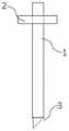
图1为本发明定位滑块的结构示意图;1 is a schematic structural diagram of a positioning slider of the present invention;
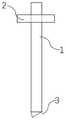
图2为针尖的端部与量针的横截面中心之间的水平距离为0时的测量装置;Figure 2 is the measuring device when the horizontal distance between the end of the needle tip and the center of the cross section of the measuring needle is 0;
图3为针尖的端部与量针的横截面中心之间的水平距离为量针的横截面半径时的测量装置;Figure 3 is the measuring device when the horizontal distance between the end of the needle tip and the center of the cross-section of the measuring needle is the radius of the cross-section of the measuring needle;
图4为针尖的端部与量针的横截面中心之间的水平距离为量针的1/2横截面半径时的测量装置;Figure 4 is a measuring device when the horizontal distance between the end of the needle tip and the center of the cross-section of the measuring needle is 1/2 of the cross-sectional radius of the measuring needle;
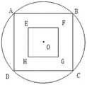
图5为测量点位置图;Figure 5 is the location map of the measuring point;
图中:1、量针;2、定位滑块;3、针尖;4、圆孔;5、缺口。In the picture: 1. Measuring needle; 2. Positioning slider; 3. Needle tip; 4. Round hole; 5. Notch.
具体实施方式Detailed ways
下文对本发明的示例性实施例进行了详细描述。尽管这些示例性实施例被充分详细地描述以使得本领域技术人员能够实施本发明,但应当理解可实现其他实施例且可在不脱离本发明的精神和范围的情况下对本发明作各种改变。下文对本发明的实施例的更详细的描述并不用于限制所要求的本发明的范围,而仅仅为了进行举例说明且不限制对本发明的特点和特征的描述,以提出执行本发明的最佳方式,并足以使得本领域技术人员能够实施本发明。因此,本发明的范围仅由所附权利要求来限定。Exemplary embodiments of the present invention are described in detail below. Although these exemplary embodiments have been described in sufficient detail to enable those skilled in the art to practice the invention, it should be understood that other embodiments may be realized and various changes may be made without departing from the spirit and scope of the invention . The following more detailed description of embodiments of the invention is not intended to limit the scope of the invention as claimed, but is intended to illustrate and not limit the description of the features and characteristics of the invention to suggest the best mode for carrying out the invention , and is sufficient to enable those skilled in the art to practice the present invention. Accordingly, the scope of the present invention is to be limited only by the appended claims.
实施例Example
一种平底盲孔的底面平面度测量装置,用于对平底盲孔的底面平面度,尤其适用于采用常规设备和方法难以测量平面度的孔径小于2mm、深径比大于10的平底盲孔,下面对其具体结构进行详细描述。A device for measuring the flatness of the bottom surface of a flat-bottomed blind hole is used to measure the flatness of the bottom surface of the flat-bottomed blind hole, and is especially suitable for the flat-bottomed blind hole with a diameter of less than 2 mm and a depth-to-diameter ratio greater than 10, which is difficult to measure flatness by conventional equipment and methods. Its specific structure will be described in detail below.
如图1至图4所示,该测量装置包括量针1、定位滑块2和针尖3。其中,量针1为圆柱结构,采用工具钢、锰钢、陶瓷和钨钢中的任意一种或多种刚性材料制备,本实施例为工具钢。定位滑块2采用弹性材料制备,本实施例为橡胶,其内侧具有直径小于量针1的圆孔4,圆孔4一侧的定位滑块2上具有缺口5,定位滑块2套设在量针1上。针尖3位于量针1的底部,根据实际测量需求调整针尖3的端部距离量针1的横截面中心之间的水平距离。制备测量装置时,为了保证用于与盲孔底部接触的针尖3的端部的位置精准,对于针尖3和量针1需要采用一体成型的加工方式。As shown in FIG. 1 to FIG. 4 , the measuring device includes a measuring
区别于传统的滑槽滑轨安装等滑动连接结构,本实施例直接采用弹性材料制备的定位滑块2通过过盈配合套装在量针1上,与量针1之间贴合紧密,在对定位滑块2下端面与针尖3端部之间的高度差进行测量时,定位滑块2不易发生松动,有效地提高了测量的精准度。Different from the traditional sliding connection structure such as chute and slide rail installation, this embodiment directly adopts the
本实施例中,为了保证最后的测量结果精准,定位滑块2的下端面的平面度不大于0.005mm,且其下端面与量针1的母线的垂直度不大于0.01mm。In this embodiment, in order to ensure the accuracy of the final measurement result, the flatness of the lower end surface of the
具体的测量方法包括以下步骤:The specific measurement method includes the following steps:
一、准备1. Preparation
准备一组测量装置,使每个测量装置的针尖3的端部与量针2的中心点之间的水平距离不同。本实施例中,如图2至图4所示,采用一组共三个测量装置,其中,装置I的针尖3的端部距离量针的横截面中心之间的水平距离为0,装置II的针尖3的端部距离量针的横截面中心之间的水平距离为量针的横截面半径,装置III的针尖3的端部距离量针的横截面中心之间的水平距离为量针的1/2横截面半径。A set of measuring devices is prepared so that the horizontal distance between the end of the
为了保证测量精准,量针1的直径小于盲孔的直径0.05-0.1mm,且硬度需大于HV350,防止量针1弯曲而影响测量结果,量针1的长度需大于盲孔的深度。In order to ensure accurate measurement, the diameter of the measuring
二、测量2. Measurement
如图5所示,首先,控制装置I的量针1伸入盲孔内,使针尖3的端部与盲孔底面接触,并使定位滑块2的下端面接触盲孔的上端面,然后取出量针1,测出定位滑块2的下端面与针尖3的端部之间的高度差并记录,此时测量的为O点的盲孔深度。As shown in FIG. 5 , first, the measuring
接着,控制装置II重复上述操作,并在测量和数据记录后转动90°再次测量,依次测量出A、B、C和D点的盲孔深度。Next, the control device II repeats the above-mentioned operations, and after measurement and data recording, rotates 90° to measure again, and sequentially measures the blind hole depths at points A, B, C and D.
最后,控制装置III重复上述操作,并在测量和数据记录后转动90°再次测量,依次测量出E、F、G和H点的盲孔深度。Finally, the control device III repeats the above-mentioned operations, and after the measurement and data recording, rotates 90° to measure again, and sequentially measures the blind hole depths at points E, F, G and H.
三、计算3. Calculation
对每个测量点进行多次测量,并求得每个测量点的深度的极差和平均深度,然后通过打表法选取测量点数据,计算出盲孔底部的平面度。Perform multiple measurements on each measurement point, and obtain the range and average depth of the depth of each measurement point, and then select the measurement point data by punching the table method to calculate the flatness of the bottom of the blind hole.
1、需要说明的是,由于本方案采用接触式测量,测量力的大小会导致针尖压入深度的不同影响测量结果。但是,运用本方法,在实际测量时,对同样的材料来说,在提取有限数目的点时,量针1的测量力来自量针1自重和测量操作,所造成的形变有限,而且操作量针1的每次测量力大致相同,所以测量力对各点的影响应是相同的,对平面度评定结果不造成影响,可以忽略。1. It should be noted that, since this solution adopts contact measurement, the size of the measurement force will cause the different indentation depths of the needle tip to affect the measurement results. However, using this method, in the actual measurement, for the same material, when extracting a limited number of points, the measuring force of the measuring
下面给出具体测量时的一些数据来对本方法进一步体现,一共是五组测量数据,每组对每个测量点测量五次,选取O、A、B、C、D五个测量点的数据计算,具体见表1至表5。Some data during specific measurement are given below to further embody this method. There are five groups of measurement data in total. Each group measures each measurement point five times, and selects the data of five measurement points O, A, B, C, and D to calculate , see Table 1 to Table 5 for details.
表1Table 1

表2Table 2

表3table 3

表4Table 4

表5table 5

综上所述,本实施例的一种平底盲孔的底面平面度测量装置和方法,解决了现有的孔径小于2mm、深径比大于10的平底盲孔的平面度测量十分困难的问题,能够精准地测量出较大深径比的微小平底盲孔的底面平面度。To sum up, the device and method for measuring the flatness of the bottom surface of a flat-bottomed blind hole in this embodiment solves the problem that it is very difficult to measure the flatness of the existing flat-bottomed blind hole with a diameter of less than 2 mm and a depth-to-diameter ratio greater than 10. It can accurately measure the bottom surface flatness of small flat-bottom blind holes with large aspect ratio.
本发明所述实例仅仅是对本发明的优选实施方式进行描述,并非对本发明构思和范围进行限定,在不脱离本发明设计思想的前提下,本领域工程技术人员对本发明的技术方案作出的各种变形和改进,均应落入本发明的保护范围。The examples described in the present invention are only to describe the preferred embodiments of the present invention, and do not limit the concept and scope of the present invention. Deformations and improvements should fall within the protection scope of the present invention.
Claims (10)
Translated fromChinesePriority Applications (1)
| Application Number | Priority Date | Filing Date | Title |
|---|---|---|---|
| CN202210460266.9ACN114674207B (en) | 2022-04-28 | 2022-04-28 | Bottom surface flatness measuring device and method for flat-bottom blind hole |
Applications Claiming Priority (1)
| Application Number | Priority Date | Filing Date | Title |
|---|---|---|---|
| CN202210460266.9ACN114674207B (en) | 2022-04-28 | 2022-04-28 | Bottom surface flatness measuring device and method for flat-bottom blind hole |
Publications (2)
| Publication Number | Publication Date |
|---|---|
| CN114674207Atrue CN114674207A (en) | 2022-06-28 |
| CN114674207B CN114674207B (en) | 2024-04-12 |
Family
ID=82079974
Family Applications (1)
| Application Number | Title | Priority Date | Filing Date |
|---|---|---|---|
| CN202210460266.9AActiveCN114674207B (en) | 2022-04-28 | 2022-04-28 | Bottom surface flatness measuring device and method for flat-bottom blind hole |
Country Status (1)
| Country | Link |
|---|---|
| CN (1) | CN114674207B (en) |
Citations (20)
| Publication number | Priority date | Publication date | Assignee | Title |
|---|---|---|---|---|
| GB565556A (en)* | 1942-08-12 | 1944-11-15 | Ford Motor Co | Improved measuring instrument |
| GB1449457A (en)* | 1973-01-04 | 1976-09-15 | Forrest J O | Measurement reference apparatus |
| FR2678726A1 (en)* | 1991-07-01 | 1993-01-08 | Aerospatiale | Device for measuring the length of the cylindrical part of a countersunk hole |
| US20030217479A1 (en)* | 2002-05-24 | 2003-11-27 | Shen He Yun | Tool and method for measuring depth of countersunk portion of a hole |
| US20070088366A1 (en)* | 2005-10-13 | 2007-04-19 | Alberto Fernandez | Depth gauge |
| JP2007147591A (en)* | 2005-11-29 | 2007-06-14 | Machvision Inc | Analysis method of dents or protrusions in micropores after copper filling |
| JP3141561U (en)* | 2008-02-26 | 2008-05-08 | 株式会社ミツトヨ | Surface roughness measuring device |
| US20080104855A1 (en)* | 2006-11-07 | 2008-05-08 | Eidosmed Llc | Digital depth gauge |
| CN102087087A (en)* | 2010-11-25 | 2011-06-08 | 西南铝业(集团)有限责任公司 | Measuring tool and method for measuring pinhole depth and curvature |
| WO2013123932A1 (en)* | 2012-02-21 | 2013-08-29 | Breitmeier Messtechnik Gmbh | Measurement device and method for measuring the surface microstructure profile or the roughness of a surface of a body |
| US20150040414A1 (en)* | 2012-01-20 | 2015-02-12 | Mitsubishi Heavy Industries, Ltd. | Hole-shape measuring apparatus and hole-shape measuring method |
| CN105841595A (en)* | 2016-05-30 | 2016-08-10 | 苏州卓诚钛设备有限公司 | Flatness measurement tool |
| CN205561706U (en)* | 2016-03-14 | 2016-09-07 | 潍柴动力股份有限公司 | A measuring apparatu for measuring distance between blind hole terminal surface and orientating group face |
| CN205785042U (en)* | 2016-05-30 | 2016-12-07 | 苏州卓诚钛设备有限公司 | Survey flatness frock |
| CN207751435U (en)* | 2018-02-05 | 2018-08-21 | 东莞市恒成汽车装备科技有限公司 | A kind of deep hole measurement of planeness cubing |
| CN210603114U (en)* | 2019-09-24 | 2020-05-22 | 苏州英示测量科技有限公司 | Measure measuring device of blind hole degree of depth |
| CN213714269U (en)* | 2020-09-04 | 2021-07-16 | 中国航空工业集团公司西安飞行自动控制研究所 | Auxiliary depth measuring tool for non-flat-bottom deep hole |
| CN215676838U (en)* | 2021-07-30 | 2022-01-28 | 宁夏北鼎新材料产业技术有限公司 | Metal casting inspection device |
| CN215725624U (en)* | 2021-06-29 | 2022-02-01 | 晋西工业集团有限责任公司 | Blind hole depth auxiliary detection tool |
| CN215725623U (en)* | 2021-06-29 | 2022-02-01 | 晋西工业集团有限责任公司 | Blind hole depth auxiliary detection device |
- 2022
- 2022-04-28CNCN202210460266.9Apatent/CN114674207B/enactiveActive
Patent Citations (21)
| Publication number | Priority date | Publication date | Assignee | Title |
|---|---|---|---|---|
| GB565556A (en)* | 1942-08-12 | 1944-11-15 | Ford Motor Co | Improved measuring instrument |
| GB1449457A (en)* | 1973-01-04 | 1976-09-15 | Forrest J O | Measurement reference apparatus |
| FR2678726A1 (en)* | 1991-07-01 | 1993-01-08 | Aerospatiale | Device for measuring the length of the cylindrical part of a countersunk hole |
| US20030217479A1 (en)* | 2002-05-24 | 2003-11-27 | Shen He Yun | Tool and method for measuring depth of countersunk portion of a hole |
| US20070088366A1 (en)* | 2005-10-13 | 2007-04-19 | Alberto Fernandez | Depth gauge |
| CN101874737A (en)* | 2005-10-13 | 2010-11-03 | 新特斯有限责任公司 | Depth gauge |
| JP2007147591A (en)* | 2005-11-29 | 2007-06-14 | Machvision Inc | Analysis method of dents or protrusions in micropores after copper filling |
| US20080104855A1 (en)* | 2006-11-07 | 2008-05-08 | Eidosmed Llc | Digital depth gauge |
| JP3141561U (en)* | 2008-02-26 | 2008-05-08 | 株式会社ミツトヨ | Surface roughness measuring device |
| CN102087087A (en)* | 2010-11-25 | 2011-06-08 | 西南铝业(集团)有限责任公司 | Measuring tool and method for measuring pinhole depth and curvature |
| US20150040414A1 (en)* | 2012-01-20 | 2015-02-12 | Mitsubishi Heavy Industries, Ltd. | Hole-shape measuring apparatus and hole-shape measuring method |
| WO2013123932A1 (en)* | 2012-02-21 | 2013-08-29 | Breitmeier Messtechnik Gmbh | Measurement device and method for measuring the surface microstructure profile or the roughness of a surface of a body |
| CN205561706U (en)* | 2016-03-14 | 2016-09-07 | 潍柴动力股份有限公司 | A measuring apparatu for measuring distance between blind hole terminal surface and orientating group face |
| CN105841595A (en)* | 2016-05-30 | 2016-08-10 | 苏州卓诚钛设备有限公司 | Flatness measurement tool |
| CN205785042U (en)* | 2016-05-30 | 2016-12-07 | 苏州卓诚钛设备有限公司 | Survey flatness frock |
| CN207751435U (en)* | 2018-02-05 | 2018-08-21 | 东莞市恒成汽车装备科技有限公司 | A kind of deep hole measurement of planeness cubing |
| CN210603114U (en)* | 2019-09-24 | 2020-05-22 | 苏州英示测量科技有限公司 | Measure measuring device of blind hole degree of depth |
| CN213714269U (en)* | 2020-09-04 | 2021-07-16 | 中国航空工业集团公司西安飞行自动控制研究所 | Auxiliary depth measuring tool for non-flat-bottom deep hole |
| CN215725624U (en)* | 2021-06-29 | 2022-02-01 | 晋西工业集团有限责任公司 | Blind hole depth auxiliary detection tool |
| CN215725623U (en)* | 2021-06-29 | 2022-02-01 | 晋西工业集团有限责任公司 | Blind hole depth auxiliary detection device |
| CN215676838U (en)* | 2021-07-30 | 2022-01-28 | 宁夏北鼎新材料产业技术有限公司 | Metal casting inspection device |
Non-Patent Citations (2)
| Title |
|---|
| 孟凡增: "超高压容器人造水晶高压釜超深度盲孔检测手段", 压力容器, no. 06* |
| 舒平生;: "深孔综合参数测试装置设计及测试方法研究", 工具技术, no. 06, 20 June 2017 (2017-06-20)* |
Also Published As
| Publication number | Publication date |
|---|---|
| CN114674207B (en) | 2024-04-12 |
Similar Documents
| Publication | Publication Date | Title |
|---|---|---|
| CN205102763U (en) | Flatness detecting jig | |
| CN213456497U (en) | Static bending force detection device of flexible circuit board | |
| CN201811915U (en) | Test system for initial defect of specimen | |
| CN221859454U (en) | A roller inspection tool | |
| CN114674207A (en) | Bottom surface flatness measuring device and method for flat-bottom blind hole | |
| CN219403542U (en) | Y-direction hole detection device for milling machine screw nut seat | |
| CN2685818Y (en) | Shell member centre hole depth measuring instrument | |
| CN217844988U (en) | Tapered roller measuring instrument | |
| CN217442469U (en) | Thin needle contact type rock mass structural plane three-dimensional morphology measuring instrument | |
| CN216815295U (en) | Measuring tool for detecting span of lead screw | |
| CN113188402B (en) | Spring detection tool | |
| CN112082458B (en) | Building engineering construction monitor | |
| CN210718892U (en) | Axial position measuring device | |
| CN107752229B (en) | A shoe last measuring instrument | |
| CN207544461U (en) | A shoe last measuring instrument | |
| CN219223575U (en) | Support and device for measuring thickness and flatness of sheet | |
| CN213238675U (en) | Exchange blade holder precision detection device | |
| CN207894371U (en) | A kind of multi-faceted altimeter of precision workpiece | |
| CN220250885U (en) | General gauge for outer cone | |
| CN213090671U (en) | Article surface flatness measuring device | |
| CN216115811U (en) | Horizontal lathe bed guide rail precision detection frock | |
| CN222027577U (en) | Roller runout measuring device | |
| CN220322278U (en) | On-vehicle camera CAS face measuring tool | |
| CN205785043U (en) | A kind of horizontal plane deflection measuring apparatus | |
| CN219121353U (en) | Sheet thickness gauge |
Legal Events
| Date | Code | Title | Description |
|---|---|---|---|
| PB01 | Publication | ||
| PB01 | Publication | ||
| SE01 | Entry into force of request for substantive examination | ||
| SE01 | Entry into force of request for substantive examination | ||
| GR01 | Patent grant | ||
| GR01 | Patent grant |