CN114668190A - Nebulizer for Lateral Induction - Google Patents
Nebulizer for Lateral InductionDownload PDFInfo
- Publication number
- CN114668190A CN114668190ACN202210281050.6ACN202210281050ACN114668190ACN 114668190 ACN114668190 ACN 114668190ACN 202210281050 ACN202210281050 ACN 202210281050ACN 114668190 ACN114668190 ACN 114668190A
- Authority
- CN
- China
- Prior art keywords
- atomizing
- atomization
- hole
- liquid
- porous body
- Prior art date
- Legal status (The legal status is an assumption and is not a legal conclusion. Google has not performed a legal analysis and makes no representation as to the accuracy of the status listed.)
- Pending
Links
Images


Classifications
- A—HUMAN NECESSITIES
- A24—TOBACCO; CIGARS; CIGARETTES; SIMULATED SMOKING DEVICES; SMOKERS' REQUISITES
- A24F—SMOKERS' REQUISITES; MATCH BOXES; SIMULATED SMOKING DEVICES
- A24F40/00—Electrically operated smoking devices; Component parts thereof; Manufacture thereof; Maintenance or testing thereof; Charging means specially adapted therefor
- A24F40/40—Constructional details, e.g. connection of cartridges and battery parts
- A24F40/46—Shape or structure of electric heating means
- A—HUMAN NECESSITIES
- A24—TOBACCO; CIGARS; CIGARETTES; SIMULATED SMOKING DEVICES; SMOKERS' REQUISITES
- A24F—SMOKERS' REQUISITES; MATCH BOXES; SIMULATED SMOKING DEVICES
- A24F40/00—Electrically operated smoking devices; Component parts thereof; Manufacture thereof; Maintenance or testing thereof; Charging means specially adapted therefor
- A24F40/10—Devices using liquid inhalable precursors
- A—HUMAN NECESSITIES
- A24—TOBACCO; CIGARS; CIGARETTES; SIMULATED SMOKING DEVICES; SMOKERS' REQUISITES
- A24F—SMOKERS' REQUISITES; MATCH BOXES; SIMULATED SMOKING DEVICES
- A24F40/00—Electrically operated smoking devices; Component parts thereof; Manufacture thereof; Maintenance or testing thereof; Charging means specially adapted therefor
- A24F40/40—Constructional details, e.g. connection of cartridges and battery parts
- A24F40/42—Cartridges or containers for inhalable precursors
- A—HUMAN NECESSITIES
- A24—TOBACCO; CIGARS; CIGARETTES; SIMULATED SMOKING DEVICES; SMOKERS' REQUISITES
- A24F—SMOKERS' REQUISITES; MATCH BOXES; SIMULATED SMOKING DEVICES
- A24F40/00—Electrically operated smoking devices; Component parts thereof; Manufacture thereof; Maintenance or testing thereof; Charging means specially adapted therefor
- A24F40/40—Constructional details, e.g. connection of cartridges and battery parts
- A24F40/44—Wicks
- A—HUMAN NECESSITIES
- A24—TOBACCO; CIGARS; CIGARETTES; SIMULATED SMOKING DEVICES; SMOKERS' REQUISITES
- A24F—SMOKERS' REQUISITES; MATCH BOXES; SIMULATED SMOKING DEVICES
- A24F40/00—Electrically operated smoking devices; Component parts thereof; Manufacture thereof; Maintenance or testing thereof; Charging means specially adapted therefor
- A24F40/40—Constructional details, e.g. connection of cartridges and battery parts
- A24F40/48—Fluid transfer means, e.g. pumps
- A24F40/485—Valves; Apertures
- A—HUMAN NECESSITIES
- A24—TOBACCO; CIGARS; CIGARETTES; SIMULATED SMOKING DEVICES; SMOKERS' REQUISITES
- A24F—SMOKERS' REQUISITES; MATCH BOXES; SIMULATED SMOKING DEVICES
- A24F47/00—Smokers' requisites not otherwise provided for
- H—ELECTRICITY
- H05—ELECTRIC TECHNIQUES NOT OTHERWISE PROVIDED FOR
- H05B—ELECTRIC HEATING; ELECTRIC LIGHT SOURCES NOT OTHERWISE PROVIDED FOR; CIRCUIT ARRANGEMENTS FOR ELECTRIC LIGHT SOURCES, IN GENERAL
- H05B3/00—Ohmic-resistance heating
- H05B3/20—Heating elements having extended surface area substantially in a two-dimensional plane, e.g. plate-heater
- H05B3/22—Heating elements having extended surface area substantially in a two-dimensional plane, e.g. plate-heater non-flexible
Landscapes
- Catching Or Destruction (AREA)
- Electrostatic Spraying Apparatus (AREA)
Abstract
Translated fromChinese
Description
Translated fromChinese技术领域technical field
本发明涉及电子烟雾化器技术领域,更具体的说,本发明涉及一种横向导液的雾化器。The present invention relates to the technical field of electronic cigarette atomizers, and more particularly, the present invention relates to an atomizer for lateral liquid conduction.
背景技术Background technique
现有的电子雾化设备,其基本任务是提供加热过程,将电子雾化设备内储存的雾化液如电子烟烟液等溶液转化为气雾、烟雾、气溶胶、蒸气等。The basic task of the existing electronic atomization equipment is to provide a heating process to convert the atomized liquid stored in the electronic atomization equipment, such as electronic cigarette liquid and other solutions, into aerosol, smoke, aerosol, vapor, and the like.
电子雾化设备,一般包括可拆卸连接的电池组件和雾化器,电池组件内安装有电池,该电池用于给雾化器供应电源,雾化器包括安装于雾化座上的雾化芯,雾化芯在通电时可将待雾化的溶液即雾化液加热雾化成气雾或气溶胶。Electronic atomization equipment, generally including a detachable battery assembly and an atomizer, a battery is installed in the battery assembly, the battery is used to supply power to the atomizer, and the atomizer includes an atomization core installed on the atomization seat , the atomizing core can heat and atomize the solution to be atomized, that is, the atomizing liquid, into aerosol or aerosol when it is energized.
市场上现有雾化器的雾化芯,开始出现多孔体导液材料,雾化液一般从储液腔流动至多孔体的上表面,上表面再渗透至下表面进行雾化,需渗透穿过整个多孔体,导液效果差,容易导致雾化量不足。另外,电子雾化设备的雾化器包括雾化器壳体、雾化罩、雾化芯、雾化座、底座、连接电极等,配件多、结构复杂,且雾化芯的发热电阻需要焊接电极引线,雾化芯安装到雾化器内时,包括需要在连接电极引线时进行穿孔引出,工艺复杂,难于实现自动化生产。The atomizing core of the existing atomizers on the market begins to appear porous liquid-conducting materials. The atomizing liquid generally flows from the liquid storage chamber to the upper surface of the porous body, and the upper surface penetrates to the lower surface for atomization. Through the entire porous body, the liquid guiding effect is poor, and it is easy to cause insufficient atomization. In addition, the atomizer of the electronic atomization device includes the atomizer shell, the atomization cover, the atomization core, the atomization seat, the base, the connection electrode, etc., with many accessories and complex structure, and the heating resistance of the atomization core needs to be welded When the electrode lead and the atomizing core are installed in the atomizer, including the need to perforate and lead out when connecting the electrode lead, the process is complicated and it is difficult to realize automatic production.
发明内容SUMMARY OF THE INVENTION
本发明为克服上述技术的不足而提供一种横向导液的雾化器。The present invention provides a transverse liquid-conducting atomizer to overcome the deficiencies of the above-mentioned technologies.
本发明的技术方案是这样实现的:包括外壳,所述外壳的内上部设有储存雾化液的储液腔,所述外壳的内底部套接设有上下连接的底座和电极座,所述外壳的中心设有上下连通且与所述储液腔分隔的气流通道,所述气流通道内设有雾化腔,所述雾化腔内横向架设有雾化芯,所述雾化芯设有横向的中心通孔,所述中心通孔的两端连通至所述储液腔,所述雾化芯包括多孔体,所述多孔体的至少一面设为雾化面,所述雾化面上敷设有发热层,所述发热层的两个远端分别连接设有电极盘,所述发热层设有供雾化液或气雾流出的雾化通孔,所述雾化液可横向进入所述中心通孔并渗透至所述多孔体的雾化面,所述发热层通电发热时使雾化液蒸发成气雾并通过气流通道排出,所述电极座上设有弹性电极,所述弹性电极抵触连接于所述电极盘上。The technical scheme of the present invention is realized as follows: including a casing, the inner upper part of the casing is provided with a liquid storage chamber for storing the atomized liquid, the inner bottom of the casing is sleeved with a base and an electrode seat connected up and down, the The center of the outer casing is provided with an air flow channel that communicates up and down and is separated from the liquid storage cavity, an atomization cavity is arranged in the air flow channel, and an atomization core is arranged transversely in the atomization cavity, and the atomization core is provided with A transverse central through hole, two ends of the central through hole are connected to the liquid storage cavity, the atomizing core includes a porous body, at least one side of the porous body is set as an atomizing surface, and the atomizing surface is A heating layer is laid, two distal ends of the heating layer are respectively connected with electrode plates, and the heating layer is provided with an atomization through hole for the outflow of the atomized liquid or aerosol, and the atomized liquid can enter the The central through hole penetrates into the atomization surface of the porous body. When the heating layer is energized and heated, the atomized liquid is evaporated into a mist and discharged through the airflow channel. The electrode holder is provided with an elastic electrode. The electrodes are in contact with the electrode disk.
优选地,所述底座的上端面连接设有雾化芯座,所述雾化芯座的内部设有上下贯通的雾化通道,所述雾化通道为所述气流通道的其中一段,所述雾化腔设于所述雾化通道内,所述雾化芯座的两侧分别设有将所述储液腔与中心通孔连通的进液通孔。Preferably, an atomization core seat is connected to the upper end surface of the base, and an atomization channel that runs through up and down is arranged inside the atomization core seat, and the atomization channel is one section of the airflow channel. The atomization cavity is arranged in the atomization channel, and the two sides of the atomization core seat are respectively provided with liquid inlet through holes connecting the liquid storage cavity and the central through hole.
优选地,所述雾化芯座的内部两侧分别嵌设有支撑块,所述进液通孔设于所述支撑块上,所述雾化芯的两端分别连接于所述支撑块的内侧,所述雾化芯座由硬质材料制成,所述支撑块由软质材料构成,所述雾化芯座与支撑块一体成型制成。Preferably, support blocks are embedded on both sides of the inner part of the atomization core seat, the liquid inlet through holes are provided on the support blocks, and both ends of the atomization core are respectively connected to the support blocks. On the inner side, the atomization core seat is made of hard material, the support block is made of soft material, and the atomization core seat and the support block are integrally formed.
优选地,所述雾化通道的上端内侧壁处径向向内设有环形凸肩,所述环形凸肩的下部沿雾化通道的内侧壁向上设有环形槽,所述环形槽用于阻挡、吸附气雾向上流出时携带的冷凝液滴。Preferably, an annular shoulder is arranged radially inward at the inner side wall of the upper end of the atomization channel, and an annular groove is formed on the lower part of the annular shoulder along the inner side wall of the atomization channel, and the annular groove is used for blocking , Absorb the condensed droplets carried by the aerosol when it flows upwards.
优选地,所述多孔体除雾化面以外的外表面设有覆膜层,所述覆膜层由致密陶瓷层、或金属氧化物镀膜层、或塑胶层、或硅胶层构成。Preferably, the outer surface of the porous body except the atomized surface is provided with a coating layer, and the coating layer is composed of a dense ceramic layer, or a metal oxide coating layer, or a plastic layer, or a silica gel layer.
优选地,所述雾化面设于所述多孔体的底面以及相对的两个侧面。Preferably, the atomizing surface is provided on the bottom surface and two opposite side surfaces of the porous body.
优选地,所述雾化面设为圆弧形的曲面。Preferably, the atomization surface is set as an arc-shaped curved surface.
优选地,所述雾化芯还包括座体,所述中心通孔设于所述座体内,所述座体的其中一面沿所述中心通孔的方向设有安装凹槽,所述安装凹槽的内部与所述中心通孔贯通,所述安装凹槽的内侧壁嵌设所述多孔体,所述多孔体向外的一面设为所述雾化面。Preferably, the atomizing core further comprises a seat body, the central through hole is provided in the seat body, and one surface of the seat body is provided with an installation groove along the direction of the central through hole, and the installation groove The inside of the groove communicates with the central through hole, the porous body is embedded in the inner side wall of the installation groove, and the outward surface of the porous body is set as the atomization surface.
优选地,所述多孔体由多孔陶瓷体、或微孔玻璃体、或微孔金属体构成,所述发热层由多孔金属片、或金属镀膜构成,所述电极盘由金属片、或金属印刷层构成。Preferably, the porous body is composed of a porous ceramic body, a microporous glass body, or a microporous metal body, the heat generating layer is composed of a porous metal sheet or a metal coating, and the electrode disk is composed of a metal sheet or a metal printing layer constitute.
优选地,所述金属镀膜包括过渡膜与发热膜,所述过渡膜与发热膜均设有所述雾化通孔,所述雾化通孔为微通孔。Preferably, the metal coating film includes a transition film and a heating film, the transition film and the heating film are both provided with the atomization through holes, and the atomization through holes are micro through holes.
本发明横向导液的雾化器的有益效果是:该横向导液的雾化器,包括储液腔和雾化腔,安装时,将雾化芯装于雾化器的壳体内,且雾化芯横向置于雾化腔中,雾化芯的中心通孔两端直接连通至储液腔,储液腔中的雾化液即可畅通地流动至中心通孔内,中心通孔内的雾化液可向多孔体四周渗透扩散,使供液迅速充分,保证足够的雾化量;另外,本发明的雾化器及其雾化芯,结构简单,电极盘无需焊接引线,可与弹簧电极进行弹性连接,可以非常方便地组装到雾化器内,有助于实现雾化器的自动化生产。The beneficial effect of the lateral liquid-guiding atomizer of the present invention is that: the lateral liquid-guiding atomizer includes a liquid storage chamber and an atomizing chamber, and during installation, the atomizing core is installed in the shell of the atomizer, and the atomization is The atomizing core is placed horizontally in the atomizing chamber, and both ends of the central through hole of the atomizing core are directly connected to the liquid storage chamber, and the atomized liquid in the liquid storage chamber can flow smoothly into the central through hole, and the The atomizing liquid can permeate and diffuse around the porous body, so that the liquid supply is quick and sufficient, and a sufficient amount of atomization is ensured; in addition, the atomizer and the atomizing core of the present invention have a simple structure, the electrode plate does not need to be welded with leads, and can be combined with the spring. The electrodes are elastically connected, which can be easily assembled into the atomizer, which is helpful for the automatic production of the atomizer.
附图说明Description of drawings
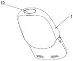
图1为本发明实施例雾化器的立体视图;1 is a perspective view of an atomizer according to an embodiment of the present invention;
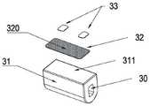
图2为本发明实施例雾化器的立体结构分解图;2 is an exploded view of the three-dimensional structure of the atomizer according to the embodiment of the present invention;
图3为本发明实施例雾化器的正面剖视图;Fig. 3 is the front sectional view of the atomizer of the embodiment of the present invention;
图4为本发明实施例雾化器的侧面剖视图;Fig. 4 is the side sectional view of the atomizer of the embodiment of the present invention;
图5为本发明实施例雾化器的雾化组件的剖视图;5 is a cross-sectional view of an atomizing assembly of an atomizer according to an embodiment of the present invention;
图6为本发明实施例雾化器的雾化芯座的立体分解结构图;6 is a perspective exploded structural view of an atomizing core seat of an atomizer according to an embodiment of the present invention;
图7为本发明实施例雾化器的雾化芯座的剖视图;7 is a cross-sectional view of an atomizing core seat of an atomizer according to an embodiment of the present invention;
图8为本发明实施例雾化器的雾化芯的立体视图一;8 is a perspective view one of the atomizing core of the atomizer according to the embodiment of the present invention;
图9为本发明实施例雾化器的雾化芯的立体分解结构图一;9 is a perspective exploded structural diagram 1 of the atomizing core of the atomizer according to the embodiment of the present invention;
图10为本发明实施例雾化器的发热层的立体分解结构图;FIG. 10 is a three-dimensional exploded structural view of the heating layer of the atomizer according to the embodiment of the present invention;
图11为本发明实施例雾化器的雾化芯的立体分解结构图二;Fig. 11 is a perspective exploded structural diagram 2 of the atomizing core of the atomizer according to the embodiment of the present invention;
图12为本发明实施例雾化器的雾化芯的立体分解结构图三;12 is a three-dimensional exploded structural diagram of the atomizing core of the atomizer according to the embodiment of the present invention;
图13为本发明实施例雾化器的雾化芯的立体分解结构图四;Fig. 13 is the three-dimensional exploded structure diagram 4 of the atomizing core of the atomizer of the embodiment of the present invention;
图14为本发明实施例雾化器的雾化芯的立体视图二;Fig. 14 is the second perspective view of the atomizing core of the atomizer according to the embodiment of the present invention;
图15为本发明实施例雾化器的雾化芯的立体分解结构图五;Fig. 15 is a three-dimensional exploded structural diagram 5 of the atomizing core of the atomizer according to the embodiment of the present invention;
图16为本发明实施例雾化器的雾化芯的多孔体的立体视图。16 is a perspective view of the porous body of the atomizing core of the atomizer according to the embodiment of the present invention.
具体实施方式Detailed ways
为了使本发明的目的、技术方案及优点更加清楚明白,以下结合附图及实施例,对本发明进行进一步详细说明。In order to make the objectives, technical solutions and advantages of the present invention clearer, the present invention will be further described in detail below with reference to the accompanying drawings and embodiments.
本发明横向导液的雾化器,与电池组件连接可以组成电子烟。为便于行文描述,如图3所示将该横向导液的雾化器的吸口10朝上竖直放置,本文所述有关各部件的“上、下、上部、下部、上端、下端、上面、下面、向上、向下”等描述,均是指在吸口朝上竖直放置时的上下位置关系。The atomizer for lateral liquid conduction of the present invention can be connected with the battery assembly to form an electronic cigarette. For the convenience of description, as shown in FIG. 3, the
实施例一Example 1
如图1-图4所示,本实施例的横向导液的雾化器,设有外壳1,外壳1的内上部设有储液腔13,外壳1的内底部套接设有底座4和电极座5,外壳1的中心设有上下连通且与储液腔13分隔的气流通道7,气流通道7内设有雾化腔201,雾化腔201内横向架设有雾化芯3。底座4的上端面连接设有雾化芯座2,雾化芯座2的内部设有上下贯通的雾化通道20,雾化通道20为气流通道7的其中一段,雾化腔201设于雾化通道20的下部。具体是,外壳1的上端设有吸口10及下端设有开口12,吸口10向外壳内延伸设有出雾管11,开口12内套接设有底座4和电极座5,出雾管11的下端连接设有雾化芯座2,出雾管11与雾化芯座2的连接处还设有密封套8。雾化芯座2的下端连接底座4,外壳1的内壁与出雾管11、雾化芯座2和底座4之间的空腔构成储液腔13,底座4由软性材料如硅胶制成,以便与壳体1的内壁、以及与雾化芯座2的底部形成密封连接,防止储液腔13的雾化液泄露。雾化芯座2的两侧分别设有连通储液腔13的进液通孔210,雾化芯座2的内部设有上下贯通的雾化通道20,雾化通道20的下部设有雾化腔201,雾化腔201内横向架设有雾化芯3,雾化芯3的两侧设有空隙使雾化通道20保持上下连通。雾化芯3内部设有横向的中心通孔30,中心通孔30的两端连通并正对进液通孔210,即进液通孔210将储液腔13与中心通孔30连通。As shown in FIGS. 1 to 4 , the horizontal liquid-conducting atomizer of this embodiment is provided with a
如图5、图6、图7所示,图5为雾化组件,包括密封套8、雾化芯座2、雾化芯3、底座4的组合结构。雾化芯座2为上小下大的结构,雾化芯座2的上端套接于出雾管11的下端,中部内径及外径均扩大,底端形成为一压盖23,压盖23的外侧壁与外壳1的内壁套接,压盖23抵接于底座4上。雾化芯座2的内底部即雾化腔201的两侧分别嵌设有支撑块21,进液通孔210设于支撑块21上,雾化芯3的两端分别连接于支撑块21的内侧,雾化芯座2由硬质材料如塑胶制成,支撑块21由软质材料如硅胶构成,雾化芯座2与支撑块21一体成型制成。其中,雾化芯座2的两侧设有安装孔22,支撑块21的外侧位于进液通孔210处设有与凸部211,凸部211恰好嵌设于安装孔22内。支撑块21具有支撑雾化芯3以及在雾化芯座2与雾化芯3端部之间起到密封作用,保证储液腔13与中心通孔30连通的同时,隔绝储液腔13与雾化通道20之间的连通,防止漏液。As shown in FIGS. 5 , 6 and 7 , FIG. 5 shows the atomization assembly, including the combined structure of the
如图7所示,雾化通道20的上端内侧壁处径向向内设有环形凸肩24,环形凸肩24的下部沿雾化通道20的内侧壁向上设有环形槽25,环形槽25用于阻挡、吸附气雾向上流出时携带的冷凝液滴,避免气雾中未被完全雾化的小液滴或冷凝液滴被吸入用户口中,造成不好的使用体验。As shown in FIG. 7 , the inner side wall of the upper end of the
如图1-图5所示,电极座5上设有两个弹性电极51,弹性电极51抵触连接于雾化芯的电极盘33上。电极座5上还设有磁体52,以便使该雾化器与电池组件进行磁力连接。底座4和电极座5的中心分别设有上下连通的进气通道6,进气通道6向上与雾化腔201连通。另底座4上还设有注液通孔40,电极座5上设有柱塞53用于给储液腔13注液后封堵注液通孔40。本发明的雾化器及其雾化芯,结构简单,电极盘33无需焊接引线,可与弹簧电极51进行弹性连接,可非常方便地组装到雾化器内,有助于实现雾化器的自动化生产。As shown in FIGS. 1-5 , the
如图8、图9所示,雾化芯3包括多孔体31,多孔体31的一面设为雾化面311,雾化面311上敷设有发热层32,发热层32的两个远端分别连接设有电极盘33,发热层32设有供雾化液或气雾流出的雾化通孔320,储液腔13存储的雾化液可横向进入中心通孔30并渗透至雾化面311,发热层32通电发热时使雾化液蒸发成气雾,气雾散发至雾化腔201。本实施例中的雾化芯3,其雾化面311设于雾化芯3的底部,发热层32加热产生的气雾自雾化芯3的底部散发后经雾化芯3的两侧空隙向上流动。As shown in FIG. 8 and FIG. 9 , the
如图3中自A点为起点的连续箭头方向为雾化液流动的方向,即雾化器工作时,雾化液自储液腔13流动,经进液通孔210进入中心通孔30。本发明的雾化芯3装于雾化器的壳体内,且雾化芯3横向置于雾化腔201中,雾化芯的中心通孔30的两端直接连通至储液腔13,储液腔13中的雾化液即可畅通地流动至中心通孔30内,中心通孔30内的雾化液可向多孔体31四周渗透扩散,使供液迅速充分,保证足够的雾化量,给用户提供良好的吸烟体验。The direction of the continuous arrows starting from point A in FIG. 3 is the direction of the flow of the atomized liquid, that is, when the atomizer is working, the atomized liquid flows from the
如图4中自B点向C点的连续箭头方向,为气体流动的方向,即雾化器工作时,外界气体自底座4和电极座5的进气通道6流入到雾化腔201,雾化液在多孔体的雾化面311上被加热雾化,在雾化腔201内产生气雾并被进入的气体携带,继续向上流经雾化通道20、出雾管11、吸口10后被吸入用户口中。上述进气通道6、雾化腔201、雾化通道20、出雾管11和吸口10共同构成气流通道7。The direction of the continuous arrow from point B to point C in FIG. 4 is the direction of gas flow, that is, when the atomizer is working, the outside air flows into the
本实施例中,多孔体31为多孔陶瓷体,发热层32为金属镀膜,该金属镀膜由金属纳米镀膜构成,金属镀膜上的雾化通孔320是许多均匀分布且微米级的微通孔320,微通孔320可使多孔体31内的雾化液从金属镀膜渗出并雾化。电极盘33由金属银印刷层构成,金属银具有良好的导电性能和良好的接触效果,且不易分解、具有良好的稳定性能。本发明中的发热层32为金属镀膜,金属镀膜的发热面积很大,同时气雾可无阻碍地从微通孔中释放出来,雾化液的雾化量得到极大的提高;金属镀膜整个面发热,受热均匀,不容易产生积碳与漏液的现象;在高温工作下没有不均衡的热应力,金属镀膜没有断路风险,使得产品的使用一致性得到提升,给用户带来良好的使用体验。In this embodiment, the
如图10所示,本实施例的发热层32的金属镀膜包括过渡膜321与发热膜322,金属镀膜的外侧还设有保护膜323。过渡膜321与发热膜322、保护膜323相互贴合连接,过渡膜321与发热膜322、保护膜323均设有微通孔便于雾化液渗出并雾化。过渡膜321由金属钛构成、主要不用于发热,发热膜322由金属铂构成、主要用于发热。发热膜322选用铂金属,系因考虑到铂Pt不仅具有较低的电阻率,更重要是因它的化学惰性,可以有效地阻止薄膜与陶瓷基底间在工作高温下的相互扩散导致阻值升高影响雾化芯工作的一致性。过渡膜321钛层不仅可以增强金属铂Pt与基底的粘附性,而且可以在雾化器工作的高温下阻止金属铂与陶瓷基体中的硅材料发生反应生成硅化物。As shown in FIG. 10 , the metal plating film of the
本实施例中保护膜323由氮化硅材料构成,保护膜323用以保护发热膜322,具有防止发热膜被氧化、腐蚀,同时具有绝缘作用。In this embodiment, the
实施例二
如图11所示,在实施例一所述结构特点的基础上,本实施例的多孔体31除雾化面311以外的外表面还设有覆膜层34。由于在雾化设备工作时因雾化通道产生负压,雾化液容易从多孔体31的非雾化面渗漏出来,未雾化的液滴容易被吸入用户口中,造成用户不良体验。该覆膜层34由致密、不可渗透的材料制成,包裹了多孔体31的非雾化面,可避免雾化液从多孔体31渗漏,从而改善上述不足。在本实施例中,覆膜层34由致密陶瓷层构成,多孔体31由多孔陶瓷体构成,两者可由不同的陶瓷基体材料一体成型后烧结制成。As shown in FIG. 11 , on the basis of the structural features described in the first embodiment, the
在其他实施例中,覆膜层34也可由金属氧化物镀膜层、或塑胶层、或硅胶层构成。In other embodiments, the
实施例三
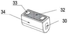
如图12所示,在实施例一所述结构特点的基础上,本实施例将雾化面311设于多孔体31的底面以及相对的两个侧面,即包括雾化芯3的底面和两个侧面的三个面都可发热雾化,这样可以增加雾化面积、加大雾化量,使用户具有更好的雾化吸食体验。As shown in FIG. 12 , on the basis of the structural features described in the first embodiment, in this embodiment, the
实施例四
如图13所示,在实施例一所述结构的基础上,本实施例将雾化芯底部的雾化面311设为圆弧形的曲面,发热膜32以曲面镀膜的形式贴附于雾化面311上,电极盘33由金属银印刷层的形式构成。雾化面311设为圆弧形的曲面,使得在相同空间增加了雾化面积从而增加雾化量,使用户具有更好吸食体验。As shown in FIG. 13 , on the basis of the structure described in the first embodiment, in this embodiment, the
实施例五
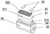
如图14、图15、图16所示,在实施例一所述结构特点的基础上,本实施例的雾化芯3,还包括座体34,中心通孔30横向设于座体34的中心,座体34的其中一面沿中心通孔30的方向设有安装凹槽341,安装凹槽341的内部与中心通孔30贯通,安装凹槽341的内侧壁嵌设有耐热且可渗透雾化液的多孔体31,多孔体31向外的一面设雾化面311,有通电可发热的发热层32,发热层32的两个远端分别连接设有电极盘33,电极盘33敷设于发热层32的表面,用于连接提供电源的电极。多孔体31朝向中心通孔30的一面沿中心通孔30纵向设有导液槽312,设有导液槽312可减少多孔体31自导液槽一面至雾化面311的厚度,以便雾化液可以更快地渗透至雾化面311。中心通孔30的两端可将雾化液导入多孔体31内,雾化液可在多孔体31内渗透至雾化面311并被发热层32加热蒸发成气雾。As shown in FIG. 14 , FIG. 15 and FIG. 16 , on the basis of the structural features described in the first embodiment, the
本发明实施例的座体34由致密陶瓷体构成,多孔体31由多孔陶瓷体构成,两者由不同的陶瓷基体材料成型为一体后烧结制成。发热层32由金属镀膜构成。金属镀膜设有雾化通孔320,雾化通孔320便于雾化液或气雾通过,金属镀膜通电发热时使雾化面311上的雾化液蒸发成气雾并从雾化通孔320散发出来。本实施例的雾化芯设有座体34,使雾化芯3具有更好的密封、绝缘和隔热效果。The
在其它实施例中,座体34也可由硬质塑胶体构成,多孔体31也可由微孔玻璃体、或微孔金属体构成,发热层32也可由发热电阻丝、或多孔金属片构成,电极盘33也可由金属片、或金属镀膜构成,电极盘33也可连接电极引线。多孔体31与发热层32之间还可设有绝缘层。在其它实施例中,雾化芯3也可将其雾化面311设于雾化芯3的上部。In other embodiments, the
以上所描述的仅为本发明的较佳实施例,上述具体实施例不是对本发明的限制。在本发明的技术思想范畴内,可以出现各种变形及修改,凡本领域的普通技术人员根据以上描述所做的润饰、修改或等同替换,均属于本发明所保护的范围。The above descriptions are only preferred embodiments of the present invention, and the above specific embodiments do not limit the present invention. Within the scope of the technical idea of the present invention, various deformations and modifications may occur, and all modifications, modifications or equivalent replacements made by those of ordinary skill in the art according to the above descriptions belong to the scope of protection of the present invention.
Claims (10)
Priority Applications (4)
| Application Number | Priority Date | Filing Date | Title |
|---|---|---|---|
| CN202210281050.6ACN114668190A (en) | 2022-03-21 | 2022-03-21 | Nebulizer for Lateral Induction |
| US18/848,935US20250204593A1 (en) | 2022-03-21 | 2023-02-16 | Vaporizer allowing for transversely guiding liquid |
| PCT/CN2023/076501WO2023179257A1 (en) | 2022-03-21 | 2023-02-16 | Atomizer for transverse liquid guide |
| EP23773508.9AEP4477100A4 (en) | 2022-03-21 | 2023-02-16 | Atomizer for transverse liquid guide |
Applications Claiming Priority (1)
| Application Number | Priority Date | Filing Date | Title |
|---|---|---|---|
| CN202210281050.6ACN114668190A (en) | 2022-03-21 | 2022-03-21 | Nebulizer for Lateral Induction |
Publications (1)
| Publication Number | Publication Date |
|---|---|
| CN114668190Atrue CN114668190A (en) | 2022-06-28 |
Family
ID=82075082
Family Applications (1)
| Application Number | Title | Priority Date | Filing Date |
|---|---|---|---|
| CN202210281050.6APendingCN114668190A (en) | 2022-03-21 | 2022-03-21 | Nebulizer for Lateral Induction |
Country Status (4)
| Country | Link |
|---|---|
| US (1) | US20250204593A1 (en) |
| EP (1) | EP4477100A4 (en) |
| CN (1) | CN114668190A (en) |
| WO (1) | WO2023179257A1 (en) |
Cited By (4)
| Publication number | Priority date | Publication date | Assignee | Title |
|---|---|---|---|---|
| CN115088880A (en)* | 2022-07-29 | 2022-09-23 | 深圳市赛尔美电子科技有限公司 | Liquid atomization method and atomization device |
| CN115281385A (en)* | 2022-07-29 | 2022-11-04 | 深圳麦克韦尔科技有限公司 | Electronic atomization device and its atomizer, atomizing core and manufacturing method of atomizing core |
| WO2023179257A1 (en)* | 2022-03-21 | 2023-09-28 | 惠州市新泓威科技有限公司 | Atomizer for transverse liquid guide |
| WO2023179258A1 (en)* | 2022-03-21 | 2023-09-28 | 惠州市新泓威科技有限公司 | Atomization core provided with liquid-guiding central through-hole |
Citations (7)
| Publication number | Priority date | Publication date | Assignee | Title |
|---|---|---|---|---|
| CN108308711A (en)* | 2018-01-15 | 2018-07-24 | 惠州市新泓威科技有限公司 | Electronic cigarette atomizer |
| CN109414078A (en)* | 2018-09-10 | 2019-03-01 | 深圳麦克韦尔股份有限公司 | Electronic cigarette, atomizing component and its nebulising element |
| CN208850676U (en)* | 2018-07-13 | 2019-05-14 | 惠州市新泓威科技有限公司 | Atomizer with integrated transverse atomizing core and electronic cigarette thereof |
| CN215075502U (en)* | 2021-03-18 | 2021-12-10 | 深圳市华诚达发展有限公司 | Elastic electrode and electronic atomization device |
| CN215224772U (en)* | 2020-11-18 | 2021-12-21 | 深圳市非我科技有限公司 | Atomizer capable of conveniently and quickly discharging oil smoke |
| CN215224778U (en)* | 2021-03-12 | 2021-12-21 | 吉万(深圳)科技有限公司 | Ceramic atomizing core, atomizer and aerosol generating device |
| CN113826962A (en)* | 2021-09-22 | 2021-12-24 | 东莞市维万特智能科技有限公司 | Atomizing core, atomizer, aerosol generating device and preparation method of atomizing core |
Family Cites Families (12)
| Publication number | Priority date | Publication date | Assignee | Title |
|---|---|---|---|---|
| CN105962421B (en)* | 2016-07-01 | 2018-12-25 | 林光榕 | Using the electronic smoke atomizer of ultrasonic atomization unit |
| CN106820269B (en)* | 2017-01-12 | 2023-04-07 | 惠州市新泓威科技有限公司 | Electronic cigarette atomizer |
| CN110464052B (en)* | 2019-08-06 | 2025-01-10 | 深圳麦克韦尔科技有限公司 | Atomizer assembly, atomizer and electronic atomizer device |
| CN110558632B (en)* | 2019-10-23 | 2024-06-14 | 深圳市你我网络科技有限公司 | Atomizer and electronic cigarette |
| CN212877607U (en)* | 2020-04-10 | 2021-04-06 | 惠州市吉瑞科技有限公司深圳分公司 | Heating ceramic body structure, atomizer and electronic cigarette |
| CN214962605U (en)* | 2021-01-29 | 2021-12-03 | 惠州市新泓威科技有限公司 | Atomizer with atomizing cavity arranged at bottom in atomizing core |
| CN113693280B (en)* | 2021-08-17 | 2024-10-15 | 惠州市新泓威科技有限公司 | Electronic atomizer for gas-liquid separation |
| CN215913321U (en)* | 2021-08-26 | 2022-03-01 | 深圳雾曼科技有限公司 | Coated ceramic heating core and electronic cigarette |
| CN114041627B (en)* | 2021-09-24 | 2025-01-10 | 深圳市华诚达精密工业有限公司 | Heating atomization core and electronic atomization device thereof |
| CN113876042A (en)* | 2021-09-26 | 2022-01-04 | 深圳市克莱鹏科技有限公司 | Cigarette bullet and electron cigarette |
| CN217364699U (en)* | 2022-03-21 | 2022-09-06 | 惠州市新泓威科技有限公司 | Electronic cigarette atomizer capable of transversely guiding liquid |
| CN114668190A (en)* | 2022-03-21 | 2022-06-28 | 惠州市新泓威科技有限公司 | Nebulizer for Lateral Induction |
- 2022
- 2022-03-21CNCN202210281050.6Apatent/CN114668190A/enactivePending
- 2023
- 2023-02-16WOPCT/CN2023/076501patent/WO2023179257A1/ennot_activeCeased
- 2023-02-16USUS18/848,935patent/US20250204593A1/enactivePending
- 2023-02-16EPEP23773508.9Apatent/EP4477100A4/enactivePending
Patent Citations (7)
| Publication number | Priority date | Publication date | Assignee | Title |
|---|---|---|---|---|
| CN108308711A (en)* | 2018-01-15 | 2018-07-24 | 惠州市新泓威科技有限公司 | Electronic cigarette atomizer |
| CN208850676U (en)* | 2018-07-13 | 2019-05-14 | 惠州市新泓威科技有限公司 | Atomizer with integrated transverse atomizing core and electronic cigarette thereof |
| CN109414078A (en)* | 2018-09-10 | 2019-03-01 | 深圳麦克韦尔股份有限公司 | Electronic cigarette, atomizing component and its nebulising element |
| CN215224772U (en)* | 2020-11-18 | 2021-12-21 | 深圳市非我科技有限公司 | Atomizer capable of conveniently and quickly discharging oil smoke |
| CN215224778U (en)* | 2021-03-12 | 2021-12-21 | 吉万(深圳)科技有限公司 | Ceramic atomizing core, atomizer and aerosol generating device |
| CN215075502U (en)* | 2021-03-18 | 2021-12-10 | 深圳市华诚达发展有限公司 | Elastic electrode and electronic atomization device |
| CN113826962A (en)* | 2021-09-22 | 2021-12-24 | 东莞市维万特智能科技有限公司 | Atomizing core, atomizer, aerosol generating device and preparation method of atomizing core |
Cited By (4)
| Publication number | Priority date | Publication date | Assignee | Title |
|---|---|---|---|---|
| WO2023179257A1 (en)* | 2022-03-21 | 2023-09-28 | 惠州市新泓威科技有限公司 | Atomizer for transverse liquid guide |
| WO2023179258A1 (en)* | 2022-03-21 | 2023-09-28 | 惠州市新泓威科技有限公司 | Atomization core provided with liquid-guiding central through-hole |
| CN115088880A (en)* | 2022-07-29 | 2022-09-23 | 深圳市赛尔美电子科技有限公司 | Liquid atomization method and atomization device |
| CN115281385A (en)* | 2022-07-29 | 2022-11-04 | 深圳麦克韦尔科技有限公司 | Electronic atomization device and its atomizer, atomizing core and manufacturing method of atomizing core |
Also Published As
| Publication number | Publication date |
|---|---|
| EP4477100A4 (en) | 2025-06-25 |
| EP4477100A1 (en) | 2024-12-18 |
| WO2023179257A1 (en) | 2023-09-28 |
| US20250204593A1 (en) | 2025-06-26 |
Similar Documents
| Publication | Publication Date | Title |
|---|---|---|
| CN114668190A (en) | Nebulizer for Lateral Induction | |
| CN112120291B (en) | Atomizer core, atomizer and electronic atomization device | |
| US20210195940A1 (en) | Electronic cigarette and atomizer thereof | |
| CN217364699U (en) | Electronic cigarette atomizer capable of transversely guiding liquid | |
| CN212911688U (en) | Atomizer and aerosol generating device thereof | |
| CN114947219A (en) | Electron smog spinning disk atomiser with soft atomizing core | |
| CN113455736B (en) | Atomizer and electronic atomization device | |
| CN209768989U (en) | Atomizing device and electronic atomizing equipment | |
| WO2022088898A1 (en) | Atomizer having integrated atomization assembly and reservoir-type atomization core | |
| WO2022161035A1 (en) | Atomizer with atomization core having protection cover | |
| CN112931972A (en) | Atomizer with atomizing cavity at inner bottom of atomizing core | |
| CN215958369U (en) | Nebulizer and aerosol generating device | |
| CN113142667A (en) | Atomizing core, atomizer and electron cigarette | |
| WO2022198940A1 (en) | Electronic cigarette having function of preventing leakage of e-liquid and condensate | |
| WO2023019797A1 (en) | Electronic atomization device | |
| CN214962605U (en) | Atomizer with atomizing cavity arranged at bottom in atomizing core | |
| CN117243420A (en) | Heating piece, atomizer core, atomizer and electronic cigarette | |
| CN220109122U (en) | Atomizer and electronic atomization device | |
| CN218551344U (en) | Electromagnetic coil, atomization structure, atomizer and electronic atomization device | |
| CN217771508U (en) | Atomization assembly, atomizer and aerosol generating device | |
| CN216853801U (en) | Atomizing core, atomizer and electron cigarette | |
| CN215531655U (en) | Electronic atomizer | |
| CN214903779U (en) | Atomizer with atomizing core provided with sleeve | |
| CN217364691U (en) | Atomizing core with central through hole for guiding liquid | |
| WO2022161029A1 (en) | Integrated atomization core having shell |
Legal Events
| Date | Code | Title | Description |
|---|---|---|---|
| PB01 | Publication | ||
| PB01 | Publication | ||
| SE01 | Entry into force of request for substantive examination | ||
| SE01 | Entry into force of request for substantive examination |