CN114667477A - Contact Lens Solutions for Myopia Management - Google Patents
Contact Lens Solutions for Myopia ManagementDownload PDFInfo
- Publication number
- CN114667477A CN114667477ACN202080067307.7ACN202080067307ACN114667477ACN 114667477 ACN114667477 ACN 114667477ACN 202080067307 ACN202080067307 ACN 202080067307ACN 114667477 ACN114667477 ACN 114667477A
- Authority
- CN
- China
- Prior art keywords
- contact lens
- optical
- zone
- eye
- toric
- Prior art date
- Legal status (The legal status is an assumption and is not a legal conclusion. Google has not performed a legal analysis and makes no representation as to the accuracy of the status listed.)
- Granted
Links
Images


Classifications
- G—PHYSICS
- G02—OPTICS
- G02C—SPECTACLES; SUNGLASSES OR GOGGLES INSOFAR AS THEY HAVE THE SAME FEATURES AS SPECTACLES; CONTACT LENSES
- G02C7/00—Optical parts
- G02C7/02—Lenses; Lens systems ; Methods of designing lenses
- G02C7/04—Contact lenses for the eyes
- G02C7/041—Contact lenses for the eyes bifocal; multifocal
- G—PHYSICS
- G02—OPTICS
- G02C—SPECTACLES; SUNGLASSES OR GOGGLES INSOFAR AS THEY HAVE THE SAME FEATURES AS SPECTACLES; CONTACT LENSES
- G02C7/00—Optical parts
- G02C7/02—Lenses; Lens systems ; Methods of designing lenses
- G02C7/04—Contact lenses for the eyes
- G—PHYSICS
- G02—OPTICS
- G02B—OPTICAL ELEMENTS, SYSTEMS OR APPARATUS
- G02B3/00—Simple or compound lenses
- G02B3/02—Simple or compound lenses with non-spherical faces
- G02B3/06—Simple or compound lenses with non-spherical faces with cylindrical or toric faces
- G—PHYSICS
- G02—OPTICS
- G02C—SPECTACLES; SUNGLASSES OR GOGGLES INSOFAR AS THEY HAVE THE SAME FEATURES AS SPECTACLES; CONTACT LENSES
- G02C7/00—Optical parts
- G02C7/02—Lenses; Lens systems ; Methods of designing lenses
- G02C7/04—Contact lenses for the eyes
- G02C7/048—Means for stabilising the orientation of lenses in the eye
- G—PHYSICS
- G02—OPTICS
- G02C—SPECTACLES; SUNGLASSES OR GOGGLES INSOFAR AS THEY HAVE THE SAME FEATURES AS SPECTACLES; CONTACT LENSES
- G02C2202/00—Generic optical aspects applicable to one or more of the subgroups of G02C7/00
- G02C2202/02—Mislocation tolerant lenses or lens systems
- G—PHYSICS
- G02—OPTICS
- G02C—SPECTACLES; SUNGLASSES OR GOGGLES INSOFAR AS THEY HAVE THE SAME FEATURES AS SPECTACLES; CONTACT LENSES
- G02C2202/00—Generic optical aspects applicable to one or more of the subgroups of G02C7/00
- G02C2202/24—Myopia progression prevention
Landscapes
- Physics & Mathematics (AREA)
- Health & Medical Sciences (AREA)
- Ophthalmology & Optometry (AREA)
- General Physics & Mathematics (AREA)
- Optics & Photonics (AREA)
- General Health & Medical Sciences (AREA)
- Eyeglasses (AREA)
Abstract
Description
Translated fromChinese相关申请的交叉引用CROSS-REFERENCE TO RELATED APPLICATIONS
本申请要求于2019年9月25日提交且题为“A contact lens for myopia(用于近视的接触透镜)”的序列号为2019/903580的澳大利亚临时申请和于2020年2月14日提交且题为“Contact lens(接触透镜)”的序列号为2020/900412的另一澳大利亚临时申请的优先权,这两个澳大利亚临时申请的全部内容通过参引并入本文中。This application claims Australian Provisional Application Serial No. 2019/903580, filed on September 25, 2019 and entitled "A contact lens for myopia" and filed on February 14, 2020 and Priority to another Australian provisional application with serial number 2020/900412 entitled "Contact lens", the entire contents of which are incorporated herein by reference.
技术领域technical field
本公开涉及用于与患有眼轴长度相关的疾病比如近视的眼睛一起使用的接触透镜。本发明涉及用于管理眼睛的近视的接触透镜;其中,接触透镜配置有:光学区,光学区被限定成基本上关于该接触透镜的光轴定中心,该光学区用以为眼睛提供基本上环曲面的或散光的方向性提示;以及围绕光学区的非光学周边载体区,非光学周边载体区配置有基本上旋转对称的厚度轮廓,以进一步提供在时间上和空间上变化的方向性提示或光学停止信号,进而减慢、改善、控制、抑制或降低近视随着时间的进展速率。The present disclosure relates to contact lenses for use with eyes suffering from axial length-related disorders, such as myopia. The present invention relates to a contact lens for managing myopia of the eye; wherein the contact lens is configured with an optic zone defined substantially centered about the optical axis of the contact lens, the optic zone serving to provide a substantially circular ring to the eye A curved or astigmatic directional cue; and a non-optical peripheral carrier zone surrounding the optical zone, the non-optical peripheral carrier zone being configured with a substantially rotationally symmetric thickness profile to further provide a temporally and spatially varying directional cue or Optical stop signal, which in turn slows, improves, controls, inhibits or reduces the rate of myopia progression over time.
背景技术Background technique
人的眼睛在出生时是远视的,其中,眼球的长度对于眼睛的总光焦度来说过短。随着人从童年到成年,眼球会继续生长直到眼睛的屈光状态稳定。眼睛的生长被理解为由反馈机制控制并且主要由视觉体验来调节,以使眼睛的光学与眼轴长度匹配并且保持内稳态。这个过程被称为正视化。Human eyes are hyperopic at birth, where the length of the eyeball is too short for the total optical power of the eye. As a person progresses from childhood to adulthood, the eyeball continues to grow until the refractive state of the eye stabilizes. Eye growth is understood to be controlled by feedback mechanisms and regulated primarily by visual experience to match the optics of the eye to the axial length and maintain homeostasis. This process is called emmetropization.
引导正视化过程的信号通过对视网膜处接收到的光能进行调制来启动。视网膜图像特征由生物过程监测,该生物过程调制信号以使眼睛生长开始或停止、加速或减慢。这个过程在光学与眼球长度之间进行协调以实现或保持正视。从这种正视化过程中脱轨会导致屈光障碍、比如近视。据假设,增加的视网膜活动会抑制眼睛生长,并且反之亦然。The signals that guide the emmetropization process are initiated by modulating the light energy received at the retina. Retinal image features are monitored by biological processes that modulate signals to start or stop, speed up or slow down eye growth. This process coordinates between optics and eye length to achieve or maintain emmetropia. Derailment from this emmetropization process can lead to refractive impairments such as myopia. It is hypothesized that increased retinal activity inhibits eye growth, and vice versa.
在世界的许多地区,尤其是在东亚地区中,近视的发病率正在以惊人的速率增加。在近视个体中,眼睛的轴向长度与眼睛的总体焦度不匹配,从而导致远处物体聚焦在视网膜的前方。The incidence of myopia is increasing at an alarming rate in many parts of the world, especially in East Asia. In myopic individuals, the axial length of the eye does not match the overall power of the eye, causing distant objects to focus in front of the retina.
一对简单的负单视觉透镜可以矫正近视。虽然这样的装置可以在光学上纠正与眼轴长度相关联的屈光不正,但是这些装置不能解决近视进展中眼睛过度生长的根本原因。A pair of simple negative single vision lenses can correct myopia. While such devices can optically correct refractive errors associated with axial length, these devices do not address the underlying cause of eye overgrowth in myopia progression.
高度近视情况下的眼轴长度过长与严重的视力威胁状况比如白内障、青光眼、近视黄斑病以及视网膜脱离相关联。因此,仍然需要用于这种个体的下述特定光学装置:该特定光学装置不仅可以矫正潜在的屈光不正,而且还可以防止眼睛过度变长或近视过度进展,由此治疗效果随着时间基本上保持一致。Axial length in high myopia is associated with serious vision-threatening conditions such as cataracts, glaucoma, myopic macular disease, and retinal detachment. Therefore, there remains a need for a specific optical device for such individuals that not only corrects the underlying refractive error, but also prevents excessive lengthening of the eye or excessive progression of myopia, whereby the therapeutic effect is substantially over time remain consistent.
定义definition
除非在下文中另有限定,否则本文中使用的术语是通常由本领域中技术人员所使用的。Unless otherwise defined below, the terms used herein are those commonly used by those skilled in the art.
术语“近视眼睛”是指下述眼睛:已经经历近视、处于近视前期阶段、有患上近视的风险、被诊断为具有朝向近视进展的屈光状况、以及具有小于1DC的散光。The term "myopia eye" refers to an eye that has experienced myopia, is in a pre-myopia stage, is at risk of developing myopia, has been diagnosed with a refractive condition that progresses toward myopia, and has astigmatism less than 1 DC.
术语“进展性近视眼睛”是指患有确定的被诊断为进展性的近视的眼睛,其被衡量为以至少-0.25D/年的屈光误差发生改变或者以至少0.1mm/年的轴向长度发生改变。The term "progressive myopia eye" refers to an eye with established myopia diagnosed as progressive myopia, measured as a change in refractive error of at least -0.25 D/year or an axial axis of at least 0.1 mm/year Length changes.
术语“有患上近视的风险的眼睛”是指下述眼睛:这种眼睛当时可能是正视的或低度远视的,但是基于遗传因素(例如,父母双方都是近视)和/或年龄(例如,年轻时是低度远视)和/或环境因素(例如,在户外消耗的时间)和/或行为因素(例如,执行近距离任务所消耗的时间),这种眼睛已经被识别为具有增加的变近视风险。The term "eye at risk of developing myopia" refers to an eye that may be emmetropic or low hyperopic at the time, but based on genetic factors (eg, both parents are nearsighted) and/or age (eg, , low hyperopia at a young age) and/or environmental factors (eg, time spent outdoors) and/or behavioral factors (eg, time spent performing near tasks), such eyes have been identified as having increased Risk of becoming myopia.
术语“光学停止信号”或“停止信号”是指可以有利于减慢、逆转、阻止、延缓、抑制或控制眼睛的生长和/或眼睛的屈光状况的光学信号或方向性提示。The term "optical stop signal" or "stop signal" refers to an optical signal or directional cue that may be beneficial in slowing, reversing, arresting, retarding, inhibiting or controlling the growth of the eye and/or the refractive condition of the eye.
术语“在空间上变化的光学停止信号”是指在视网膜处提供的在空间上横跨眼睛的视网膜改变的光学信号或方向性提示。The term "spatially varying optical stop signal" refers to an optical signal or directional cue provided at the retina that varies spatially across the retina of the eye.
术语“在时间上变化的光学停止信号”是指在视网膜处提供的随着时间改变的光学信号或方向性提示。The term "time-varying optical stop signal" refers to a time-varying optical signal or directional cue provided at the retina.
术语“在空间上和时间上变化的光学停止信号”是指在视网膜处提供的随着时间且在空间上横跨眼睛的视网膜而改变的光学信号或方向性提示。The term "spatially and temporally varying optical stop signal" refers to an optical signal or directional cue provided at the retina that varies temporally and spatially across the retina of the eye.
术语“接触透镜”是指用以配合在佩戴者的角膜上来影响眼睛的光学性能的成品接触透镜,该成品接触透镜通常包装在小瓶、泡罩包装或类似物中。The term "contact lens" refers to a finished contact lens, typically packaged in vials, blister packs, or the like, for fitting over the cornea of the wearer to affect the optical properties of the eye.
术语“光学区”或“光区”是指接触透镜上具有处方所规定的光学效果的区域。光学区还可以被区分成具有围绕光学中心或光轴的变化的焦度分布的区域。光学区还可以通过前光区和后光区来区分。前光区和后光区是指接触透镜的前表面区域和后表面区域,前表面区域和后表面区域各自有助于处方光学效果。接触透镜的光学区可以是圆形的或椭圆形的或其他不规则形状的。接触透镜的仅具有球面焦度的光区通常是圆形的。然而,在某些实施方式中,环曲面的引入可能导致椭圆形的光学区。The term "optical zone" or "optical zone" refers to the area on a contact lens that has the optical effect specified by the prescription. The optical zone can also be distinguished as a region with a varying power distribution around an optical center or optical axis. Optical zones can also be distinguished by front and rear light zones. Front and back areas refer to the front and back surface areas of a contact lens, each of which contributes to the prescription optical effect. The optic zone of a contact lens may be circular or oval or other irregular shapes. The light area of a contact lens that has only spherical power is generally circular. However, in some embodiments, the introduction of a torus may result in an elliptical optical zone.
术语“光学中心”或“视中心”是指接触透镜的光学区的几何中心。术语“几何学的”和“几何的”在本质上是相同的。The term "optical center" or "optical center" refers to the geometric center of the optic zone of a contact lens. The terms "geometric" and "geometric" are essentially the same.
术语“光轴”是指穿过光学中心并且与接触透镜的包含边缘的平面基本上垂直的线。The term "optical axis" refers to the line passing through the optical center and substantially perpendicular to the plane of the contact lens containing the edge.
术语“混合区”是将接触透镜的光学区和周边载体区连接的区或是位于接触透镜的光学区与周边载体区之间的区。术语“混合区”与“共混区”在某些实施方式中同义并且可以位于接触透镜的前表面或后表面或两个表面上。共混区可以是两个不同的相邻表面弯曲之间的抛光的、平滑的结合部。混合区的厚度也可以被称为结合部厚度。The term "hybrid zone" is the zone connecting the optic zone and the peripheral carrier zone of the contact lens or the zone between the optic zone and the peripheral carrier zone of the contact lens. The term "mixing zone" is synonymous with "blending zone" in certain embodiments and may be located on the front surface or the back surface or both surfaces of the contact lens. The blend zone can be a polished, smooth junction between two distinct adjacent surface curvatures. The thickness of the mixing zone may also be referred to as the junction thickness.
术语“离焦”是指基本上位于视网膜前后的区域。换言之,大约正好位于视网膜前方和/或大约正好位于视网膜后方的区域。The term "out-of-focus" refers to the area substantially in front of and behind the retina. In other words, an area approximately just in front of the retina and/or approximately just behind the retina.
术语“载体区”是将接触透镜的混合区与边缘连接的非光学区或是位于接触透镜的混合区与边缘之间的非光学区。在某些实施方式中,术语“周边区”或“周边载体区”与“载体区”同义并且不具有处方所规定的光学效果。The term "carrier zone" is the non-optical zone that connects the blended zone and the rim of the contact lens or the non-optical zone that is located between the blended zone and the rim of the contact lens. In certain embodiments, the terms "peripheral zone" or "peripheral carrier zone" are synonymous with "carrier zone" and do not have the optical effects specified by the prescription.
术语或短语“球面光学区”可以是指具有均匀的焦度分布而没有大量的主球面像差的光学区。The term or phrase "spherical optical zone" may refer to an optical zone having a uniform power distribution without substantial principal spherical aberrations.
术语或短语“非球面光学区”可以是指不具有均匀的光焦度分布的光学区。在某些实施方式中,非球面光学区还可以被分类为低阶像差、比如散光或环曲面。术语或短语“散光光学区”或“环曲面光学区”可以是指具有球柱面焦度分布的光学区。The term or phrase "aspheric optical zone" may refer to an optical zone that does not have a uniform power distribution. In certain embodiments, aspheric optical zones may also be classified as lower-order aberrations, such as astigmatism or toric. The terms or phrases "astigmatic optic zone" or "toroidal optic zone" may refer to an optic zone having a sphero-cylindrical power distribution.
术语“压载”是指载体区内厚度轮廓的非旋转对称分布,这种非旋转对称分布用以影响接触透镜当安置在眼睛上时的旋转取向。The term "ballast" refers to the rotationally asymmetric distribution of the thickness profile within the carrier region which is used to affect the rotational orientation of the contact lens when placed on the eye.
术语“棱镜压载”是指用于产生楔形设计的竖向棱镜,该楔形设计将帮助稳定环曲面接触透镜在眼睛上的旋转和取向。The term "prism ballast" refers to the vertical prism used to create a wedge-shaped design that will help stabilize the rotation and orientation of the toric contact lens on the eye.
术语“削薄(slab-off)”是指靠近接触透镜的下周缘和上周缘的边缘在一个或更多个离散区域中将该接触透镜有目的地减薄,以实现所期望的接触透镜旋转稳定性。The term "slab-off" refers to the purposeful thinning of a contact lens in one or more discrete regions near the edges of the lower and upper peripheries of the contact lens to achieve the desired contact lens Rotational stability.
术语“截断”是指接触透镜的被设计成呈近乎直线的下边缘,以用于控制接触透镜的旋转稳定性。The term "truncated" refers to the lower edge of the contact lens which is designed to be nearly straight for controlling the rotational stability of the contact lens.
术语“负”、“平”或“正”载体分别是指如在距透镜直径大约0.1mm距离处所测量的边缘厚度大于结合部厚度、边缘厚度等于结合部厚度、以及边缘厚度小于结合部厚度的接触透镜。The terms "negative", "flat" or "positive" support refer to a carrier with an edge thickness greater than the bond thickness, edge thickness equal to the bond thickness, and edge thickness less than the bond thickness, respectively, as measured at a distance of approximately 0.1 mm from the diameter of the lens. contact lens.
术语“模型眼睛”可以是指示意性的、光线追踪的或物理模型眼睛。The term "model eye" may refer to a semantic, ray traced or physical model eye.
如本文中所使用的术语“屈光度”、“焦度”或“D”是屈光能力的单位量度,其被限定为透镜或光学系统沿着光轴的以米计的焦距的倒数。通常,字母“D”表示球面屈光度,并且字母“DC”表示柱面屈光度。The terms "diopter", "power" or "D" as used herein are a unit measure of refractive power, which is defined as the reciprocal of the focal length in meters of a lens or optical system along the optical axis. Typically, the letter "D" refers to spherical diopter, and the letter "DC" refers to cylindrical diopter.
术语“斯图姆氏类圆锥体”或“斯图姆氏间距”是指由于配置成基本上关于光学中心或光轴定中心的散光、环曲面或非对称的焦度轮廓而在视网膜上或围绕视网膜形成的合成的大致轴上离焦图像,其用椭圆形模糊图案表示,椭圆形模糊图案包括切向平面和矢状平面并且具有最小弥散圆。The term "Sturm's cone" or "Sturm's distance" refers to the distance on the retina or due to an astigmatism, toric or asymmetric power profile configured to be substantially centered about the optical center or optical axis. A composite roughly on-axis out-of-focus image formed around the retina, represented by an elliptical blur pattern that includes a tangential and sagittal plane and has a circle of least confusion.
术语“焦度轮廓”是指横跨光学区的局部光焦度的一维焦度轮廓,一维焦度轮廓作为以光学中心为参照位于给定方位角角度处的径向距离的函数,或者作为在给定的径向距离处测量的方位角角度的函数。The term "power profile" refers to the one-dimensional power profile of the local power across the optical zone as a function of radial distance at a given azimuthal angle with reference to the optical center, or As a function of the azimuth angle measured at a given radial distance.
术语“焦度图”是指横跨光学区的在笛卡尔坐标系或极坐标系中的二维焦度分布。术语“径向的”是指沿着方位角角度限定的从光学中心向光区的边缘辐射的方向。术语“方位角的”是指关于所限定的光轴或光学中心在径向距离处的沿着限定圆周的方向。The term "power map" refers to a two-dimensional power distribution in Cartesian or polar coordinates across the optical zone. The term "radial" refers to the direction of radiation from the optical center to the edge of the optical zone defined along the azimuthal angle. The term "azimuthal" refers to a direction along a defined circumference at radial distances with respect to a defined optical axis or optical center.
术语“后顶焦度”是指在光学区上的整个区域或特定区域上的后顶焦距的倒数,以屈光度(D)表示。术语“光区的子午线”是指围绕视中心沿任何方位角角度的任何子午线。The term "back vertex power" refers to the reciprocal of the back vertex length, expressed in diopters (D), over the entire area or a specific area over the optical zone. The term "meridian of an optical zone" refers to any meridian at any azimuthal angle around the apparent center.
术语“SPH”或“球面”焦度是指光区的所有子午线之间的基本上均匀的焦度。术语“CYL”、“柱面”焦度是指光区内两条主子午线之间的后顶焦度之差。The term "SPH" or "spherical" power refers to a substantially uniform power between all meridians of an optical zone. The terms "CYL", "cylindrical" power refer to the difference in back vertex power between two principal meridians within the optical region.
术语“非对称光区”是指局部焦度在沿着任意选择的子午线保持镜像对称的同时围绕视中心沿着方位角方向的变化。The term "asymmetric optical zone" refers to the change in local power in an azimuthal direction about the apparent center while maintaining mirror symmetry along an arbitrarily chosen meridian.
术语“子午线矫正”或“眼睛的子午线矫正”是指在眼睛的视网膜上沿至少一个子午线对眼睛进行部分矫正。术语“子午线散光”或“眼睛的子午线散光”是指沿眼睛的至少一个子午线引入或诱发的散光。The term "meridian correction" or "meridian correction of the eye" refers to partial correction of the eye along at least one meridian on the retina of the eye. The term "meridian astigmatism" or "meridian astigmatism of the eye" refers to astigmatism introduced or induced along at least one meridian of the eye.
术语“特定配合”是指非光学周边载体区配置有关于光学中心基本上旋转对称的厚度轮廓以有利于接触透镜随着时间的基本上自由的旋转。本发明中提到的特定配合是指非光学周边载体区配置有基本上不存在压载或棱镜或任何截断的厚度轮廓。The term "specific fit" means that the non-optical peripheral carrier region is configured with a thickness profile that is substantially rotationally symmetric about the optical center to facilitate substantially free rotation of the contact lens over time. The specific fit referred to in the present invention means that the non-optical peripheral carrier region is configured with a thickness profile that is substantially free of ballast or prisms or any truncated.
术语“中央凹子区域”是指与眼睛的视网膜的中央凹坑紧密相邻的区域。术语“中央凹旁区域”是指与眼睛的视网膜的中央凹区域紧密相邻的区域。The term "foveal subregion" refers to the region immediately adjacent to the fovea of the retina of the eye. The term "parafoveal area" refers to the area in close proximity to the foveal area of the retina of the eye.
术语“黄斑子区域”是指眼睛的视网膜的黄斑区域内的区域。术语“黄斑旁区域”是指与眼睛的视网膜的黄斑区域紧密相邻的区域。The term "macular subregion" refers to an area within the macular region of the retina of the eye. The term "paramacular area" refers to the area in close proximity to the macular area of the retina of the eye.
发明内容SUMMARY OF THE INVENTION
某些公开的实施方式包括用于更改进入人眼的入射光的波前特性的接触透镜。某些公开的实施方式涉及用于矫正、管理和治疗屈光不正的接触透镜的配置。Certain disclosed embodiments include contact lenses for modifying the wavefront characteristics of incident light entering the human eye. Certain disclosed embodiments relate to contact lens configurations for correcting, managing, and treating refractive errors.
所提出的发明的实施方式中的一个实施方式旨在不仅矫正近视屈光不正并且同时提供阻止进一步的眼睛生长或近视进展的光学停止信号。所提出的光学装置提供了强加在视网膜中央区域和视网膜周边区域上的基本上连续改变的散光模糊(即,光学停止信号)。One of the embodiments of the proposed invention aims to not only correct myopic refractive error but at the same time provide an optical stop signal that prevents further eye growth or myopia progression. The proposed optical device provides a substantially continuously varying astigmatic blur (ie, optical stop signal) imposed on the central retinal region and the retinal peripheral region.
本公开包括散光的接触透镜或环曲面的接触透镜,散光的接触透镜或环曲面的接触透镜被有目的地设计为不具有稳定载体区以在中央视网膜和周边视网膜上提供在时间上和空间上变化的散光模糊停止信号。The present disclosure includes astigmatic contact lenses or toric contact lenses that are purposely designed without a stable carrier zone to provide temporal and spatial temporal and spatial distribution on the central and peripheral retinas Changed astigmatism blur stop signal.
所提出的另一实施方式是一种非对称的接触透镜,非对称的接触透镜用于矫正近视屈光不正并且还提供抑制进一步的眼睛生长或使眼睛生长速率减慢的光学停止信号。所提出的实施方式的另一特征可以包括所提出的接触透镜的旋转非对称光学区与旋转对称载体区之间的混合部。该混合区可以是圆形的或椭圆形的。Another proposed embodiment is an asymmetric contact lens for correcting myopic refractive error and also providing an optical stop signal that inhibits further eye growth or slows the rate of eye growth. Another feature of the proposed embodiment may include a hybrid between the rotationally asymmetric optical zone and the rotationally symmetric carrier zone of the proposed contact lens. The mixing zone can be circular or oval.
配置有基本上关于光学中心或光轴定中心的环曲面矫正的某些实施方式可以通过提供在时间上和空间上变化的停止信号来克服现有技术的限制。因此,允许使近视进展的治疗效果的饱和度最小化。在另一实施方式中,本发明涉及一种用于减慢、延缓或防止近视进展中的至少一项的接触透镜。Certain embodiments configured with a toric correction centered substantially about the optical center or optical axis may overcome the limitations of the prior art by providing a temporally and spatially varying stop signal. Thus, it is allowed to minimize the saturation of the therapeutic effect of myopia progression. In another embodiment, the present invention relates to a contact lens for use in at least one of slowing, retarding or preventing progression of myopia.
本公开的另一实施方式是一种接触透镜,该接触透镜包括前表面、后表面、光学中心、围绕光学中心的光区、基本上围绕光学中心限定的环曲面的或散光的焦度轮廓,其中,环曲面的或散光的轮廓配置成至少部分地提供足够的中央凹矫正并且至少部分地提供用以降低近视进展速率的光学停止信号;所述接触透镜还配置有旋转对称的周边载体区以提供在时间上和空间上变化的光学停止信号;使得减缓眼睛生长进展的治疗效果随着时间基本上保持一致。Another embodiment of the present disclosure is a contact lens comprising an anterior surface, a posterior surface, an optical center, an optical zone surrounding the optical center, a toric or astigmatic power profile defined substantially around the optical center, wherein the toric or astigmatic profile is configured to, at least in part, provide adequate foveal correction and at least in part provide an optical stop signal to reduce the rate of myopia progression; the contact lens is further configured with a rotationally symmetric peripheral carrier region to Provides a temporally and spatially varying optical stop signal; making the therapeutic effect of slowing the progression of eye growth substantially consistent over time.
根据各实施方式中的一个实施方式,本公开涉及一种用于近视眼睛的接触透镜。接触透镜包括前表面、后表面、光轴、围绕光轴的光区、围绕光轴的非对称焦度轮廓,其中,非对称轮廓配置成至少部分地提供足够的子午线矫正并且至少部分地提供用以降低近视进展速率的光学停止信号;所述接触透镜还配置有旋转对称的周边载体区以提供在时间上和空间上变化的光学停止信号;使得减缓眼睛生长进展的治疗效果随着时间基本上保持一致。According to one of the various embodiments, the present disclosure relates to a contact lens for a myopic eye. The contact lens includes an anterior surface, a posterior surface, an optical axis, an optical zone around the optical axis, and an asymmetrical power profile around the optical axis, wherein the asymmetrical profile is configured to at least partially provide adequate meridional correction and at least partially provide usefulness. an optical stop signal to reduce the rate of myopia progression; the contact lens is also configured with a rotationally symmetric peripheral carrier region to provide a temporally and spatially varying optical stop signal; so that the therapeutic effect of slowing the progression of eye growth substantially over time be consistent.
本公开中呈现的实施方式涉及对改进的光学设计和接触透镜的持续需求,这些改进的光学设计和接触透镜可以抑制近视的进展,同时为佩戴者提供合理且足够的视觉性能以便进行佩戴者可以承担的作为他们日常生活的一部分的一系列活动。本发明公开内容的各实施方式的各个方面解决了佩戴者的这类需求。Embodiments presented in this disclosure relate to a continuing need for improved optical designs and contact lenses that can inhibit the progression of myopia while providing the wearer with reasonable and adequate visual performance so that the wearer can A range of activities undertaken as part of their daily life. Various aspects of the various embodiments of the present disclosure address such needs of the wearer.
附图说明Description of drawings
图1图示了接触透镜实施方式的前视图和横截面图。根据某些实施方式,前视图还图示了视中心、光区、混合区以及载体区。Figure 1 illustrates a front view and a cross-sectional view of an embodiment of a contact lens. According to certain embodiments, the front view also illustrates the viewing center, the light zone, the mixing zone, and the carrier zone.
图2图示了另一接触透镜实施方式的前视图和横截面图。实施方式的光区中的球柱面矫正可以导致椭圆形的光学区。根据某些实施方式,前视图还图示了,实施方式的载体区的径向横截面具有基本上近似的厚度。Figure 2 illustrates a front view and a cross-sectional view of another contact lens embodiment. Sphero-cylindrical correction in the optical zone of an embodiment may result in an elliptical optical zone. According to certain embodiments, the front view also illustrates that the radial cross-sections of the carrier regions of the embodiments have substantially similar thicknesses.
图3图示了本文中所公开的又一接触透镜实施方式的前视图。前视图还图示了接触透镜由于载体区设计的配置而基本上围绕光学中心的潜在自由旋转。根据某些实施方式,通过接触透镜的设计有基本上近似的径向厚度轮廓的载体区来便于该接触透镜的基本上自由的旋转。3 illustrates a front view of yet another contact lens embodiment disclosed herein. The front view also illustrates the potential free rotation of the contact lens substantially around the optical center due to the configuration of the carrier area design. According to certain embodiments, substantially free rotation of the contact lens is facilitated by the design of a carrier region of the contact lens with a substantially approximate radial thickness profile.
图4图示了当具有一定可见波长(例如,589nm)且聚散度为0D的入射光入射到未矫正的-3D近视模型眼睛上时在视网膜平面处的轴上几何光斑分析的示意图。4 illustrates a schematic diagram of an on-axis geometric speckle analysis at the retinal plane when incident light having a certain visible wavelength (eg, 589 nm) and a vergence of OD is incident on an uncorrected -3D myopia model eye.
图5图示了当具有一定可见波长(例如,589nm)且聚散度为0D的入射光入射到利用现有技术的单视觉接触透镜所矫正的-3D近视模型眼睛上时在视网膜平面处的轴上几何光斑分析的示意图。Figure 5 illustrates at the retinal plane when incident light having a certain visible wavelength (eg, 589 nm) and a vergence of 0D is incident on a -3D myopia model eye corrected with a prior art monovision contact lens Schematic illustration of on-axis geometric spot analysis.
图6图示了当具有一定可见波长(589nm)且聚散度为0D的入射光入射到利用本文中所公开的接触透镜实施方式中的一种接触透镜实施方式所矫正的-3D近视模型眼睛上时在视网膜平面处的轴上离焦几何光斑分析的示意图。Figure 6 illustrates a -3D myopia model eye corrected using one of the contact lens embodiments disclosed herein when incident light having a certain visible wavelength (589 nm) and a vergence of 0D is incident on the eye Schematic illustration of the on-axis defocus geometric spot analysis when on-axis at the retinal plane.
图7图示了接触透镜实施方式中的一种接触透镜实施方式的具有本文中所公开的环曲面或球柱面处方的仅光学区的放大截面的示意图。本实施方式的光学区内的焦度轮廓分布使用如本文中所公开的径向焦度分布函数和方位角焦度分布函数来配置。7 illustrates a schematic diagram of an enlarged cross-section of only the optic zone of one of the contact lens embodiments with a toric or sphero-cylindrical formulation disclosed herein. The power profile distribution within the optical zone of this embodiment is configured using the radial power distribution function and the azimuthal power distribution function as disclosed herein.
图8示出了当前公开的示例性实施方式的光学区内的焦度图分布。图9示出了本公开的示例性实施方式的整个接触透镜的径向厚度分布。FIG. 8 shows the power map distribution within the optical zone of the presently disclosed exemplary embodiment. FIG. 9 shows the radial thickness distribution of the entire contact lens of an exemplary embodiment of the present disclosure.
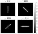
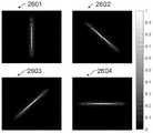
图10图示了当具有一定可见波长(例如,589nm)且聚散度为0D的入射光入射到利用图8和图9中描述的接触透镜实施方式所矫正的-3D近视模型眼睛上时在视网膜平面处的被描绘为轴上点扩散函数的由于接触透镜旋转而在时间上和空间上变化的信号。FIG. 10 illustrates a -3D myopia model eye corrected using the contact lens embodiments described in FIGS. 8 and 9 when incident light having a certain visible wavelength (eg, 589 nm) and a vergence of 0D is incident on the eye. Temporally and spatially varying signal at the retinal plane due to contact lens rotation, depicted as an on-axis point spread function.
图11图示了当具有一定可见波长(例如,589nm)且聚散度为0D的入射光入射到利用图8和图9中描述的接触透镜实施方式所矫正的-3D近视模型眼睛上时的被描绘为宽视野离焦几何光斑分析的由于接触透镜旋转而在时间上和空间上变化的信号。Figure 11 illustrates when incident light having a certain visible wavelength (eg, 589 nm) and a vergence of 0D is incident on a -3D myopia model eye corrected using the contact lens embodiments described in Figures 8 and 9 Temporally and spatially varying signal due to contact lens rotation, depicted as wide-field defocus geometry spot analysis.
图12图示了由于接触透镜旋转而被描绘为图10的在时间上和空间上变化的点扩散函数的针对主子午线和垂直子午线的轴上的离焦的、光学传递函数的模数的视网膜信号,该视网膜信号在具有一定可见波长(例如,589nm)且聚散度为0D的入射光入射到利用图8和图9中描述的接触透镜实施方式所矫正的-3D近视模型眼睛上时被计算出。12 illustrates retina for defocus, modulo of the optical transfer function on the axes of the principal and vertical meridians, plotted as the temporally and spatially varying point spread function of FIG. 10 due to contact lens rotation The retinal signal is detected when incident light having a certain visible wavelength (eg, 589 nm) and a vergence of 0D is incident on a -3D myopia model eye corrected using the contact lens embodiment described in Figures 8 and 9 Calculate.
图13示出了当前公开的另一示例性实施方式的光区内的焦度图分布。FIG. 13 shows the power map distribution within the optical region of another exemplary embodiment of the present disclosure.
图14示出了现有技术的整个接触透镜的径向厚度分布。Figure 14 shows the radial thickness distribution of the entire contact lens of the prior art.
图15示出了图13中所示的当前公开的示例性实施方式的整个接触透镜的径向厚度分布。FIG. 15 shows the radial thickness distribution of the entire contact lens of the presently disclosed exemplary embodiment shown in FIG. 13 .
图16图示了当具有一定可见波长(589nm)且聚散度为0D的入射光为入射到利用图13和图15中描述的接触透镜实施方式所矫正的-3D近视模型眼睛上时在视网膜平面处的被描绘为轴上点扩散函数的由于接触透镜旋转而在时间上和空间上变化的信号。Figure 16 illustrates the retinal appearance when incident light having a certain visible wavelength (589 nm) and a vergence of 0D is incident on a -3D myopia model eye corrected using the contact lens embodiments described in Figures 13 and 15 The temporally and spatially varying signal at the plane due to the rotation of the contact lens, depicted as the on-axis point spread function.
图17图示了当具有一定可见波长(589nm)且聚散度为0D的入射光入射到利用图13和图15中描述的接触透镜实施方式所矫正的-3D近视模型眼睛上时的被描绘为宽视野离焦几何光斑分析的由于接触透镜旋转而在时间上和空间上变化的信号。Figure 17 illustrates the depiction when incident light having a certain visible wavelength (589 nm) and a vergence of 0D is incident on a -3D myopia model eye corrected using the contact lens embodiments described in Figures 13 and 15 Temporally and spatially varying signal due to contact lens rotation for wide-field defocus geometry spot analysis.
图18图示了由于接触透镜旋转而被描绘为图16的在时间上和空间上变化的点扩散函数的针对主子午线和垂直子午线的轴上的、离焦的、光学传递函数的模数的视网膜信号,该视网膜信号在具有一定可见波长(例如,589nm)且聚散度为0D的入射光入射到利用图13和图15中描述的接触透镜实施方式所矫正的-3D近视模型眼睛上时被计算出。FIG. 18 illustrates the modulus of the on-axis, out-of-focus, optical transfer functions for the axes of the principal and perpendicular meridians, plotted as the temporally and spatially varying point spread function of FIG. 16 due to contact lens rotation. Retinal signal when incident light having a certain visible wavelength (eg, 589 nm) and a vergence of 0D is incident on a -3D myopia model eye corrected using the contact lens embodiment described in Figures 13 and 15 is calculated.
图19示出了当前公开的另一示例性实施方式的光区内的焦度图分布。FIG. 19 shows the power map distribution within the optical region of another exemplary embodiment of the present disclosure.
图20示出了当前公开的另一示例性实施方式的整个接触透镜的径向厚度分布。FIG. 20 shows the radial thickness distribution of the entire contact lens of another exemplary embodiment of the present disclosure.
图21图示了当具有一定可见波长(589nm)且聚散度为0D的入射光入射到利用图19和图20中描述的接触透镜实施方式所矫正的-3D近视模型眼睛上时在视网膜平面处的被描述为轴上点扩散函数的由于接触透镜旋转而在时间上和空间上变化的信号。Figure 21 illustrates the retinal plane when incident light having a certain visible wavelength (589nm) and a vergence of 0D is incident on a -3D myopia model eye corrected using the contact lens embodiment described in Figures 19 and 20 The temporally and spatially varying signal due to the rotation of the contact lens, described as the on-axis point spread function, at .
图22图示了当具有一定可见波长(589nm)且聚散度为0D的入射光入射到利用图19和图20中描述的接触透镜实施方式所矫正的-3D近视模型眼睛上时的被描绘为宽视野离焦几何光斑分析的由于接触透镜旋转而在时间上和空间上变化的信号。Figure 22 illustrates the depiction when incident light having a certain visible wavelength (589 nm) and a vergence of 0D is incident on a -3D myopia model eye corrected using the contact lens embodiments described in Figures 19 and 20 Temporally and spatially varying signal due to contact lens rotation for wide-field defocus geometry spot analysis.
图23图示了由于接触透镜旋转而被描绘为图21的在时间上和空间上变化的点扩散函数的针对主子午线和垂直子午线的轴上的、离焦的、光学传递函数的模数的视网膜信号,该视网膜信号在具有一定可见波长(例如589nm)和聚散度为0D的入射光入射到用图19和图20中描述的接触透镜实施方式所矫正的-3D近视模型眼睛上时被计算出。FIG. 23 illustrates the on-axis, defocused, modulo of the optical transfer function for the axes of the principal and perpendicular meridians, plotted as the temporally and spatially varying point spread function of FIG. 21 due to contact lens rotation. Retinal signal, which is detected when incident light having a certain visible wavelength (eg, 589 nm) and a vergence of 0D is incident on a -3D myopia model eye corrected with the contact lens embodiment described in Figures 19 and 20. Calculate.
图24示出了当前公开的另一示例性实施方式的光区内的焦度图分布。FIG. 24 shows the power map distribution within the optical region of another exemplary embodiment of the present disclosure.
图25示出了本公开的另一示例性实施方式的整个接触透镜的径向厚度分布。FIG. 25 shows the radial thickness distribution of the entire contact lens of another exemplary embodiment of the present disclosure.
图26图示了当具有一定可见波长(589nm)且聚散度为0D的入射光为入射到利用图24和图25中描述的接触透镜实施方式所矫正的-3D近视模型眼睛上时在视网膜平面处的被描绘为轴上点扩散函数的由于接触透镜旋转而在时间上和空间上变化的信号。Figure 26 illustrates the retinal appearance of a -3D myopia model eye corrected using the contact lens embodiment described in Figures 24 and 25 when incident light having a certain visible wavelength (589 nm) and a vergence of 0D is incident on the eye. The temporally and spatially varying signal at the plane due to the rotation of the contact lens, depicted as the on-axis point spread function.
图27图示了当具有一定可见波长(589nm)且聚散度为0D的入射光为入射到利用图24和图25中描述的接触透镜实施方式所矫正的-3D近视模型眼睛上时的被描绘为宽视野离焦几何光斑分析的由于接触透镜旋转而在时间上和空间上变化的信号。FIG. 27 illustrates the result when incident light having a certain visible wavelength (589 nm) and a vergence of 0D is incident on a -3D myopia model eye corrected using the contact lens embodiments described in FIGS. 24 and 25. Temporally and spatially varying signal due to contact lens rotation, depicted as a wide-field defocus geometry spot analysis.
图28图示了由于接触透镜旋转而被描绘为图26的在时间上和空间上变化的点扩散函数的针对主子午线和垂直子午线的轴上的、离焦的、光学传递函数的模数的视网膜信号,该视网膜信号在具有一定可见波长(例如,589nm)和聚散度为0D的入射光入射到利用图24和图25中描述的接触透镜实施方式所矫正的-3D近视模型眼睛上时被计算出。FIG. 28 illustrates the modulus of the on-axis, out-of-focus, optical transfer functions for the axes of the principal and perpendicular meridians, plotted as the temporally and spatially varying point spread function of FIG. 26 due to contact lens rotation. Retinal signal when incident light with a certain visible wavelength (eg, 589 nm) and a vergence of 0D is incident on a -3D myopia model eye corrected using the contact lens embodiments described in Figures 24 and 25 is calculated.
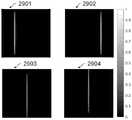
图29图示了当具有一定可见波长(589nm)且聚散度为0D的入射光入射到利用图13和图15中描述的接触透镜实施方式所矫正的-3D近视模型眼睛上时在视网膜平面处的被描绘为轴上点扩散函数的由于接触透镜偏心而在时间上和空间上变化的信号。Figure 29 illustrates the retinal plane when incident light having a certain visible wavelength (589 nm) and a vergence of 0D is incident on a -3D myopia model eye corrected using the contact lens embodiment described in Figures 13 and 15 The temporally and spatially varying signal due to the decentration of the contact lens is depicted as the on-axis point spread function at .
图30图示了当具有一定可见波长(589nm)且聚散度为0D的入射光入射到利用图13和图15中描述的接触透镜实施方式所矫正的-3D近视模型眼睛上时的被描绘为宽视野离焦几何光斑分析的由于接触透镜偏心而在时间上和空间上变化的信号。Figure 30 illustrates the depiction when incident light having a certain visible wavelength (589 nm) and a vergence of 0D is incident on a -3D myopia model eye corrected using the contact lens embodiments described in Figures 13 and 15 Temporally and spatially varying signal due to contact lens decentered analysis for wide-field defocus geometry spot analysis.
图31图示了由于接触透镜偏心而被描绘为图29的在时间上和空间上变化的点扩散函数的针对主子午线和垂直子午线的轴上的、离焦的、光学传递函数的模数的视网膜信号,该视网膜信号在具有一定可见波长(例如,589nm)且聚散度为0D的入射光入射到利用图13和图15中描述的接触透镜实施方式所矫正的-3D近视模型眼睛上时被计算出。Figure 31 illustrates the on-axis, out-of-focus, modulus of the optical transfer function for the axes of the principal and perpendicular meridians, depicted as the temporally and spatially varying point spread function of Figure 29 due to contact lens decentered Retinal signal when incident light having a certain visible wavelength (eg, 589 nm) and a vergence of 0D is incident on a -3D myopia model eye corrected using the contact lens embodiment described in Figures 13 and 15 is calculated.
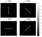
图32a图示了作为图19中描述的接触透镜实施方式的变型的原型接触透镜(透镜#1)的所测量的厚度轮廓。图32b图示了作为图19中描述的接触透镜实施方式的变型的原型接触透镜(透镜#2)的所测量的厚度轮廓。FIG. 32a illustrates the measured thickness profile of a prototype contact lens (Lens #1 ) that is a variation of the contact lens embodiment described in FIG. 19 . FIG. 32b illustrates the measured thickness profile of a prototype contact lens (Lens #2) that is a variation of the contact lens embodiment described in FIG. 19 .
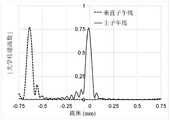
图33a图示了作为图19中描述的接触透镜实施方式的变型的原型接触透镜(透镜#1)的光区的所测量的相对子午线焦度。图33b图示了作为图19中描述的接触透镜实施方式的变型的原型接触透镜的光区的所测量的相对子午线焦度。FIG. 33a illustrates the measured relative meridional power for the optical area of a prototype contact lens (Lens #1 ) that is a variation of the contact lens embodiment described in FIG. 19 . FIG. 33b illustrates the measured relative meridional power for the optical area of a prototype contact lens that is a variation of the contact lens embodiment described in FIG. 19 .
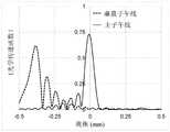
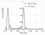
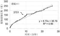
图34a图示了商业上可获得的环曲面接触透镜(对照#1)的两个主子午线(竖向子午线和水平子午线)的所测量的厚度轮廓。图34b示出了商业上可获得的环曲面接触透镜(对照#2)的两个主子午线(竖向子午线和水平子午线)的所测量的厚度轮廓。Figure 34a illustrates the measured thickness profiles for two principal meridians (vertical and horizontal) of a commercially available toric contact lens (Control #1). Figure 34b shows the measured thickness profiles for the two principal meridians (vertical and horizontal) of a commercially available toric contact lens (Control #2).
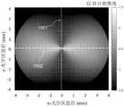
图35示出了用于对接触透镜随着时间的旋转进行测量的装置的图片。Figure 35 shows a picture of an apparatus for measuring the rotation of a contact lens over time.
图36示出了本文中所公开的接触透镜实施方式的前视图。前视图还图示了一种方法,即可以使用接触透镜上的两个标记来测量两个原型接触透镜(透镜#1和透镜#2)随着时间的方位角位置、旋转量或围绕光轴的转数。Figure 36 shows a front view of an embodiment of a contact lens disclosed herein. The front view also illustrates a method by which the two markings on the contact lenses can be used to measure the azimuthal position, amount of rotation, or around the optical axis of two prototype contact lenses (
图37a示出了一个原型接触透镜(透镜#1)随着时间、即在佩戴透镜大约30分钟内所测量的方位角定位。Figure 37a shows the azimuthal positioning of a prototype contact lens (Lens #1) measured over time, ie, approximately 30 minutes of wearing the lens.
图37b示出了一个商业可获得的环曲面接触透镜(对照#1)随着时间、即在佩戴透镜大约30分钟内所测量的方位角定位。Figure 37b shows the azimuthal positioning of a commercially available toric contact lens (Control #1) measured over time, ie, approximately 30 minutes of wearing the lens.
具体实施方式Detailed ways
在本部分中,将参照一个或更多个实施方式对本公开进行详细描述,其中一些实施方式由附图进行图示和支持。示例和实施方式通过说明的方式提供并且不应被解释为限制本公开的范围。In this section, the present disclosure will be described in detail with reference to one or more embodiments, some of which are illustrated and supported by the accompanying drawings. The examples and implementations are provided by way of illustration and should not be construed as limiting the scope of the present disclosure.
关于可以共用本公开的共同特性和特征的若干实施方式而提供以下描述。应当理解的是,一个实施方式的一个或更多个特征可以与任何其他实施方式的可以构成另外的实施方式的一个或更多个特征相结合。The following description is provided with respect to several embodiments that may share the common characteristics and features of the present disclosure. It should be understood that one or more features of one embodiment may be combined with one or more features of any other embodiment which may constitute additional embodiments.
本文中所公开的功能性和结构性信息不应被解释为以任何方式进行限制,并且应当仅被解释为用于教示本领域中技术人员以各种方式采用所公开的实施方式和这些实施方式的变型的代表性基础。The functional and structural information disclosed herein should not be construed as limiting in any way, and should only be construed as teaching one skilled in the art to variously employ the disclosed embodiments and these embodiments The representative basis of the variant.
包括在详细描述部分中使用的子标题和相关主题标题仅是为了便于读者参考,并且决不应当用于限制在整个发明或者公开的权利要求中找到的主题。子标题和相关主题标题不应当用来解释权利要求的范围或权利要求的限制。The subheadings and related subject headings used in the Detailed Description section are included for ease of reference by the reader only and should in no way be used to limit the subject matter found throughout the invention or in the disclosed claims. Subheadings and related subject headings should not be used to interpret the scope or limitation of the claims.
发展性近视或进展性近视的风险可以基于以下因素中的一者或更多者:遗传、种族、生活方式、环境、过度近距离工作等。本公开的某些实施方式针对处于发展性近视或进展性近视的风险的人。The risk of developing myopia or progressive myopia can be based on one or more of the following factors: genetics, ethnicity, lifestyle, environment, working too closely, etc. Certain embodiments of the present disclosure are directed to persons at or at risk of developing myopia.
迄今为止,已经提出了许多接触透镜光学设计来控制眼睛的生长速率,即近视进展。一些具有用于延缓近视进展速率的特征的接触透镜设计选项包括具有一定程度的相对正焦度的设计,这些设计与透镜的通常关于接触透镜的光轴旋转对称分布的处方焦度有关。To date, a number of contact lens optical designs have been proposed to control the growth rate of the eye, ie myopia progression. Some contact lens design options with features for slowing the rate of myopia progression include designs with some degree of relative positive power associated with the lens' prescription power, which is typically distributed rotationally symmetrically about the contact lens' optical axis.
基于同步图像的现有光学设计的一些问题在于,这些光学设计由于引入相当大的视觉干扰而损害了位于各种其他距离处的视觉质量。这种副作用主要归因于:相当高水平的同步散焦、相当大量的球面像差的使用、或光区内焦度的剧烈变化。Some problems with existing optical designs based on synchronized images are that these optical designs impair visual quality at various other distances by introducing considerable visual disturbance. This side effect is mainly attributable to: a relatively high level of simultaneous defocusing, the use of a relatively large amount of spherical aberration, or dramatic changes in power within the optical region.
鉴于接触透镜佩戴的顺应性对这种透镜的功效的影响,视觉性能的显著降低可能会使得顺应性较差,因此导致功效更差。Given the effect of compliance of contact lens wear on the efficacy of such lenses, a significant reduction in visual performance may result in poorer compliance and therefore worse efficacy.
正视化的简单线性模型表明停止信号的幅度随着时间累积。换言之,累积的停止信号取决于曝光的总幅度而非其时间分布。然而,本发明人已经从各种光学设计的临床试验报告中观察到,不均衡地,所实现的功效或对进展速率的减慢作用的比例在最初的6个月至12个月内较大。A simple linear model of emmetropization shows that the magnitude of the stop signal accumulates over time. In other words, the accumulated stop signal depends on the total amplitude of the exposure rather than its temporal distribution. However, the inventors have observed from clinical trial reports of various optical designs that, unevenly, the proportion of efficacy or slowing effect on progression rate achieved is greater in the first 6 to 12 months .
在最初突然开始治疗以后,可以观察到功效随着时间减弱。因此,鉴于临床观察,与临床结果一致的更忠实的正视化模型表明,在停止信号累加之前可能存在延迟,然后随着时间推移出现饱和,并且停止信号的有效性可能会衰减。Efficacy may be observed to diminish over time after initial abrupt initiation of treatment. Thus, given clinical observations, a more faithful emmetropization model consistent with clinical findings suggests that there may be a delay before the stop signal accumulates, then saturation occurs over time, and the effectiveness of the stop signal may decay.
本领域中需要一种接触透镜,该接触透镜通过提供在时间上和空间上变化的停止信号来延缓眼睛生长的速率例如延缓近视进展以使治疗效果的这种饱和最小化,而不需要给佩戴者增加在给定时间段期间于具有不同光学设计的接触透镜之间进行切换的负担。There is a need in the art for a contact lens that slows the rate of eye growth, such as myopia progression, by providing a temporally and spatially varying stop signal to minimize this saturation of the therapeutic effect without requiring wear This increases the burden of switching between contact lenses with different optical designs during a given time period.
因此,存在对具有下述机制的光学设计的需要:在不显著损害视觉性能的情况下实现在降低和/或减慢近视进展方面的随着时间基本上更大和/或基本上一致的功效。在一个或更多个示例中,功效基本上一致的加长时间可以被认为是至少6、12、18、24、36、48或60个月。Accordingly, there exists a need for an optical design with a mechanism that achieves substantially greater and/or substantially consistent efficacy over time in reducing and/or slowing myopia progression without significantly compromising visual performance. In one or more examples, an extended period of substantially consistent efficacy can be considered to be at least 6, 12, 18, 24, 36, 48, or 60 months.
本公开的各实施方式涉及一种光学干预,该光学干预利用有目的地配置的散光模糊对视觉系统的影响来抑制近视进展的速率或使近视进展的速率减速。更具体地,一些实施方式涉及一种环曲面接触透镜,该环曲面接触透镜被有目的地设计成在非光学周边载体区中不具有任何稳定或基本稳定,并且该环曲面接触透镜具有用于使速率减速或停止进展性近视屈光不正的光学特性。Embodiments of the present disclosure relate to an optical intervention that utilizes the effect of purposefully configured astigmatic blur on the visual system to suppress or slow the rate of myopia progression. More specifically, some embodiments relate to a toric contact lens that is purposefully designed to have no or substantial stability in the non-optical peripheral carrier region, and that has a toric contact lens for Optical properties that slow down or stop progressive myopic refractive errors.
光学特性可以至少部分地包括:在佩戴者眼睛的视网膜水平处引入散光模糊与旋转对称的周边载体区相结合地用作对于近视眼睛或可能正在向近视进展的眼睛的在时间上和空间上变化的停止信号。The optical properties may include, at least in part, the introduction of astigmatic blur at the level of the retina of the wearer's eye in combination with a rotationally symmetric peripheral carrier region serving as a temporal and spatial variation for myopic eyes or eyes that may be progressing toward myopia stop signal.
本公开还涉及通过利用散光提示以使近视进展速率减速的接触透镜来修改入射光的装置、方法和/或系统。The present disclosure also relates to devices, methods and/or systems for modifying incident light through a contact lens that utilizes astigmatism cues to decelerate the rate of myopia progression.
在一些实施方式中,接触透镜装置或方法基于散光模糊信号提供停止信号以延缓眼睛生长速率或者停止佩戴者眼睛的眼睛生长或屈光不正状态。在一些实施方式中,配置有旋转对称的周边载体区的所述接触透镜装置提供在时间上和空间上变化的停止信号以用于提高管理进展性近视的有效性。In some embodiments, the contact lens device or method provides a stop signal based on the astigmatism blur signal to slow the rate of eye growth or stop the eye growth or refractive error state of the wearer's eye. In some embodiments, the contact lens device configured with a rotationally symmetric peripheral carrier region provides a temporally and spatially varying stop signal for increasing the effectiveness of managing progressive myopia.
在一些实施方式中,接触透镜装置或方法并非仅基于正球面像差或同步散焦,它经受佩戴者的潜在视觉性能劣化。In some embodiments, the contact lens device or method is not based solely on positive spherical aberration or synchronous defocus, which suffers from potential degradation of the wearer's visual performance.
下面的示例性实施方式涉及通过下述接触透镜来修改入射光的方法:该接触透镜在被矫正的眼睛的视网膜平面处提供同步散光提示。这可以通过使用接触透镜的环曲面光学区以至少部分地提供对近视的子午线矫正来实现。The following exemplary embodiments relate to methods of modifying incident light by means of a contact lens that provides synchronous astigmatism cues at the retinal plane of the corrected eye. This can be achieved by using the toric optic zone of the contact lens to provide at least in part meridian correction for myopia.
接触透镜的环曲面光学区的用途可以配置有下述性质:这些性质被设计成通过在视网膜水平处引入散光方向性提示来降低近视进展速率。在某些实施方式中,利用环曲面接触透镜获得的散光方向性提示的使用可以配置成在空间上和时间上是可变的。The use of the toric optic zone of a contact lens can be configured with properties designed to reduce the rate of myopia progression by introducing astigmatic directional cues at the retinal level. In certain embodiments, the use of astigmatic directional cues obtained with toric contact lenses can be configured to be spatially and temporally variable.
本公开的某些其他实施方式涉及一种光学干预,该光学干预利用接触透镜中有目的地配置的非对称区的作用来向视觉系统提供方向性提示以抑制近视进展的速率或使近视进展的速率减速。更具体地,一些实施方式涉及所述接触透镜,该接触透镜被有目的地设计成在非光学周边载体区中不具有任何稳定或基本稳定,并且该接触透镜具有用于使速率减速或停止进展性近视屈光不正的光学特性。Certain other embodiments of the present disclosure relate to an optical intervention that utilizes the effect of purposefully configured asymmetric zones in a contact lens to provide directional cues to the visual system to inhibit the rate of myopia progression or to increase the rate of myopia progression. Speed slows down. More specifically, some embodiments relate to the contact lens that is purposefully designed to have no stabilization or substantial stabilization in the non-optical peripheral carrier region, and that has a function to slow down the rate or stop the progression. Optical properties of myopic refractive error.
图1示出了本发明的实施方式可以应用的示例性接触透镜实施方式(100)的总体结构,以未按比例的前视图(100a)和横截面图(100b)示出了该透镜。示例性接触透镜实施方式(100)的前视图还图示了包括视中心(101)、光区(102)、混合区(103)、对称的非光学周边载体区(104)以及透镜直径(105)的基板。在该示例性示例中,透镜直径为大约14mm,光区直径为大约8mm,混合区宽度为大约0.25mm,并且载体区宽度为大约2.75mm。Figure 1 shows the general structure of an exemplary contact lens embodiment (100) to which embodiments of the present invention may be applied, showing the lens in a front view (100a) and a cross-sectional view (100b), which are not to scale. The front view of the exemplary contact lens embodiment (100) also illustrates the inclusion of an apparent center (101), an optical zone (102), a mixing zone (103), a symmetric non-optical peripheral carrier zone (104), and a lens diameter (105). ) of the substrate. In this illustrative example, the lens diameter is approximately 14 mm, the light zone diameter is approximately 8 mm, the mixing zone width is approximately 0.25 mm, and the carrier zone width is approximately 2.75 mm.
图2示出了另一示例性接触透镜实施方式的未按比例的前视图(200a)和横截面图(200b)。示例性接触透镜实施方式的前视图还图示了包括视中心(201)、光区(202)、混合区(203)和非光学周边载体区(204)的基板。在该示例性示例中,透镜直径为大约14mm直径,光区(202)是球柱面的、或散光的、或环曲面的、或非对称的,光区是椭圆形的并且水平直径为大约8mm且竖向直径为大约7.5mm,混合区沿水平子午线的宽度为大约0.25mm且沿竖向子午线的宽度为大约0.38mm,并且对称的周边载体区宽度为大约2.75mm。对称的周边载体区(204)的径向横截面(204a至204h)具有相同或基本上近似的厚度轮廓。Figure 2 shows a not-to-scale front view (200a) and cross-sectional view (200b) of another exemplary contact lens embodiment. The front view of the exemplary contact lens embodiment also illustrates a substrate including an optical center (201), an optical zone (202), a hybrid zone (203), and a non-optical peripheral carrier zone (204). In this illustrative example, the lens diameter is approximately 14 mm in diameter, the optic zone (202) is spherocylindrical, or astigmatic, or toric, or asymmetric, the optic zone is elliptical and the horizontal diameter is approximately 8 mm and a vertical diameter of about 7.5 mm, the mixing zone has a width along the horizontal meridian of about 0.25 mm and a width along the vertical meridian of about 0.38 mm, and the symmetric peripheral carrier zone has a width of about 2.75 mm. The radial cross-sections (204a to 204h) of the symmetric peripheral carrier region (204) have the same or substantially similar thickness profiles.
在某些实施方式中,沿着不同径向横截面(204a至204h)的厚度轮廓的差异可以配置成实现围绕透镜的光学中心的所期望的眼上旋转。优选的眼上旋转可以通过使周边厚度轮廓横跨所有的半子午线保持旋转对称来实现。In certain embodiments, the differences in thickness profiles along the different radial cross-sections (204a-h) can be configured to achieve a desired on-ocular rotation about the optical center of the lens. Preferred supraocular rotation can be achieved by maintaining rotational symmetry of the peripheral thickness profile across all semi-meridians.
例如,径向厚度轮廓(例如,204a至204h)可以配置成使得:对于距透镜中心的任何给定距离,其他径向横截面中的任何径向横截面的厚度轮廓基本上相同或者在4%、6%、8%或10%的变化幅度内。For example, the radial thickness profiles (eg, 204a to 204h) may be configured such that, for any given distance from the center of the lens, the thickness profile of any of the other radial cross-sections is substantially the same or at 4% , 6%, 8% or 10% variation.
在一个示例中,对于距透镜中心的任何给定距离,径向厚度轮廓204a在径向厚度轮廓204e的5%、8%或10%的变化幅度内。在另一示例中,对于距透镜中心的任何给定距离,径向厚度轮廓204c在径向厚度轮廓204g的4%、6%或8%的变化幅度内。In one example, the
在又一示例中,径向厚度轮廓(例如,204a至204h)可以配置成使得对于距透镜中心的任何给定距离,径向横截面中的任何径向横截面的厚度轮廓在所有径向横截面的平均值的4%、6%、8%或10%的变化幅度内。为了确定所制造的非光学周边载体区域的径向厚度轮廓例如204a至204h是否符合它们的标称轮廓,可能需要沿着接触透镜的方位角方向在限定的径向距离处进行厚度的横截面测量。在一些其他示例中,可以将在一个径向横截面中所测量的峰值厚度与在非光学周边载体区域的另一径向横截面中所测量的峰值厚度进行比较。In yet another example, the radial thickness profiles (eg, 204a-204h) can be configured such that for any given distance from the center of the lens, the thickness profile of any one of the radial cross-sections is at all radial cross-sections. Within 4%, 6%, 8% or 10% variation of the mean value of the cross section. To determine whether the radial thickness profiles of fabricated non-optical peripheral carrier regions, such as 204a to 204h, conform to their nominal profiles, cross-sectional thickness measurements at defined radial distances along the azimuthal direction of the contact lens may be required . In some other examples, the peak thickness measured in one radial cross-section can be compared to the peak thickness measured in another radial cross-section of the non-optical peripheral carrier region.
在一些实施方式中,一个或更多个径向横截面之间的峰值厚度的差异可以不大于20μm、30μm、40μm、50μm或60μm。在一些实施方式中,一个或更多个垂直径向横截面之间的峰值厚度的差异可以不大于20μm、30μm、40μm、50μm或60μm。In some embodiments, the difference in peak thickness between one or more radial cross-sections may be no greater than 20 μm, 30 μm, 40 μm, 50 μm, or 60 μm. In some embodiments, the difference in peak thickness between one or more perpendicular radial cross-sections may be no greater than 20 μm, 30 μm, 40 μm, 50 μm, or 60 μm.
在该示例性示例中,接触透镜实施方式(200)的球柱面的或散光的或环曲面的光区(202)的球面焦度具有-3D的球面焦度以矫正-3D近视眼睛并且具有+1.25DC的柱面焦度以在眼睛的视网膜处诱发或引入子午线散光。在本公开的一些其他示例中,用以矫正和管理近视眼睛的接触透镜的球面焦度可以在-0.5D与-12D之间,并且用以在近视眼睛的视网膜处诱发或引入期望的子午线散光的可期望的散光的或环曲面的或柱面的焦度范围可以在+0.75DC至+2.5DC之间。In this illustrative example, the spherical power of the sphero-cylindrical or astigmatic or toric optical region ( 202 ) of the contact lens embodiment ( 200 ) has a spherical power of -3D to correct for -3D myopic eyes and has +1.25DC of cylindrical power to induce or introduce meridian astigmatism at the retina of the eye. In some other examples of the present disclosure, the spherical power of a contact lens used to correct and manage myopic eyes may be between -0.5D and -12D, and to induce or introduce desired meridian astigmatism at the retina of myopic eyes The desired range of astigmatic or toric or cylindrical power may be between +0.75DC and +2.5DC.
图3示出了图2中所示的示例性接触透镜(300)实施方式的前视图。该附图示意地图示了下眼睑(303)和上眼睑(304)对接触透镜实施方式(300)的取向的作用,尤其是对关于视中心(301)所限定的光学区(302)的取向的作用。FIG. 3 shows a front view of the exemplary contact lens ( 300 ) embodiment shown in FIG. 2 . This figure schematically illustrates the effect of the lower eyelid (303) and the upper eyelid (304) on the orientation of the contact lens embodiment (300), in particular on the optical zone (302) defined with respect to the center of vision (301). the role of orientation.
由于下眼睑(303)和上眼睑(304)的组合动作所促成的自然眨眼,接触透镜(300)可以在视中心(301)上旋转或关于视中心(301)周围旋转。这可能导致由限定成基本上关于光学中心或光轴定中心的光学区(302)所施加的散光的或环曲面的或非对称的刺激的取向和位置随着眨眼而变化,进而提供了基本上自由的旋转和/或偏心,从而导致在时间上和空间上变化的刺激以降低近视佩戴者的进展速率;其中,管理近视的有效性随着时间基本上保持一致。The contact lens (300) may rotate on or about the center of vision (301) due to natural blinking facilitated by the combined action of the lower eyelid (303) and the upper eyelid (304). This may result in the orientation and location of astigmatic or toric or asymmetric stimuli applied by an optical zone (302) defined substantially centered about the optical center or optical axis changing with blink, thereby providing a fundamental free rotation and/or eccentricity, resulting in temporally and spatially varying stimuli to reduce the rate of progression of myopia wearers; wherein the effectiveness of managing myopia remains substantially consistent over time.
在一些实施方式中,例如,如参照图2和图3所描述的,接触透镜被设计成至少在自然眨眼动作的影响下表现出基本上自由的旋转。例如,全天佩戴透镜,优选地佩戴透镜超过6小时至12小时,眼睑相互作用将使接触透镜易于在眼睛上以大量不同的取向或配置来定向。由于基本上围绕所述接触透镜的光学中心配置的散光的或环曲面的或非对称的光学器件,用以控制眼睛生长速率的方向性提示可以配置成在空间上和时间上变化。In some embodiments, for example, as described with reference to Figures 2 and 3, the contact lens is designed to exhibit substantially free rotation at least under the influence of a natural blinking action. For example, wearing the lens throughout the day, preferably for more than 6 hours to 12 hours, the eyelid interaction will allow the contact lens to be easily oriented in a number of different orientations or configurations on the eye. The directional cues used to control the rate of eye growth can be configured to vary both spatially and temporally due to astigmatic or toric or asymmetric optics configured substantially around the optical center of the contact lens.
在一些实施方式中,接触透镜实施方式的表面参数例如后表面半径和/或非球面度可以针对个体眼睛进行调整,使得接触透镜的期望的眼上旋转可以实现。例如,所述接触透镜可以配置成比眼睛的角膜的最平坦子午线的曲率半径平至少0.3mm,以在佩戴透镜期间增加眼上旋转的发生。In some embodiments, surface parameters of contact lens embodiments, such as posterior surface radius and/or asphericity, can be adjusted for an individual eye so that a desired on-ocular rotation of the contact lens can be achieved. For example, the contact lens may be configured to be at least 0.3 mm flatter than the radius of curvature of the flattest meridian of the cornea of the eye to increase the occurrence of on-ocular rotation during lens wear.
在其他实施方式中,接触透镜可以被设计成在佩戴透镜1小时内具有小于20度的旋转并且每佩戴一天会具有小于180度的旋转。应当理解的是,该接触透镜仍然能够仅通过透镜的随机取向来产生在时间上和空间上变化的停止信号,该随机取向由接触透镜在插入时的取向支配。In other embodiments, the contact lens may be designed to have less than 20 degrees of rotation within 1 hour of wearing the lens and less than 180 degrees of rotation per day of wear. It will be appreciated that the contact lens is still capable of producing a temporally and spatially varying stop signal only by the random orientation of the lens, which is governed by the orientation of the contact lens upon insertion.
图4示出了未矫正的-3D近视模型眼睛(400)。当聚散度为0D的一定可见波长(例如,589nm)的入射光(401)入射到未矫正的近视眼睛上时,位于视网膜上的合成图像具有由散焦引起的对称模糊(402)。该示意图表示了视网膜平面处的轴上几何光斑分析。Figure 4 shows an uncorrected-3D myopia model eye (400). When incident light (401) of a certain visible wavelength (eg, 589 nm) with vergence OD is incident on an uncorrected myopic eye, the composite image on the retina has a symmetrical blur (402) caused by defocus. This schematic represents on-axis geometric spot analysis at the retinal plane.
图5示出了当图4的-3D近视模型眼睛(500)利用现有技术的单视觉球面接触透镜(501)来矫正时视网膜平面处的轴上几何光斑分析的示意图。在此,在该示例中,当聚散度为0D的可见波长(例如,589nm)的入射光(502)入射到经矫正的近视眼睛上时,视网膜上的合成图像具有对称的清晰焦点(503)。Figure 5 shows a schematic diagram of on-axis geometric speckle analysis at the retinal plane when the -3D myopia model eye (500) of Figure 4 is corrected using a prior art single vision spherical contact lens (501). Here, in this example, when incident light (502) at a visible wavelength (eg, 589 nm) with a vergence of 0D is incident on a corrected myopic eye, the composite image on the retina has a symmetrical sharp focus (503 ).
图6示出了当图4的-3D近视模型眼睛(600)利用本文中所公开的示例性实施方式中的一个示例性实施方式的接触透镜(602)来矫正时视网膜平面处的轴上、离焦、几何光斑分析的示意图。在此,在该示例中,当聚散度为0D的可见波长(例如,589nm)的入射光(601)入射到经矫正的近视眼睛(600)上时,视网膜上的合成离焦图像形成斯图姆氏类锥体或间距(603),其具有最小弥散圆(605)以及关于切向平面(604)和矢状平面(606)的椭圆形模糊图案。视网膜后方的图像(607和608)都失焦。在该示例中,本公开的示例性实施方式配置成使得矢状平面位于视网膜上而切向平面和最小弥散圆都位于视网膜的前方。模糊圆大小的图形尺寸为200μm。Figure 6 shows the on-axis, on-axis, retinal plane when the -3D myopia model eye (600) of Figure 4 is corrected using the contact lens (602) of one of the exemplary embodiments disclosed herein Schematic representation of out-of-focus, geometric spot analysis. Here, in this example, when incident light ( 601 ) of a visible wavelength (eg, 589 nm) with a vergence of 0D is incident on a corrected myopic eye ( 600 ), a composite out-of-focus image on the retina forms a Tum's cone or spacing (603) with a circle of least confusion (605) and an elliptical blur pattern about the tangential plane (604) and the sagittal plane (606). The images behind the retina (607 and 608) are both out of focus. In this example, exemplary embodiments of the present disclosure are configured such that the sagittal plane lies on the retina and the tangential plane and the circle of least confusion lie in front of the retina. The size of the pattern of the blur circle size is 200 μm.
位于视网膜前方的切向平面(604)中的椭圆形模糊图案被称为子午线散光,而矢状平面(606)中的椭圆形模糊图案被称为子午线矫正。The elliptical blur pattern in the tangential plane (604) in front of the retina is called meridian astigmatism, and the elliptical blur pattern in the sagittal plane (606) is called meridian correction.
在另一示例中,接触透镜实施方式(602)可以被规定成使得切向平面(604)中的椭圆形模糊图案位于视网膜前方并且矢状平面(606)中的椭圆形模糊图案不位于视网膜后方。斯图姆氏类锥体或间距的深度、即矢状平面与切向平面之间的离焦距离可以配置成在约+0.5DC至+3DC之间。切向平面(604)中的椭圆形模糊图案的位置可以位于视网膜前方0.6mm与0.13mm之间。矢状平面(606)中的椭圆形模糊图案的位置可以位于视网膜前方约0.13mm与0mm之间。In another example, the contact lens embodiment (602) may be specified such that the elliptical blur pattern in the tangential plane (604) is located in front of the retina and the elliptical blur pattern in the sagittal plane (606) is not located behind the retina . The depth of the Sturm-like cone or spacing, ie the defocus distance between the sagittal and tangential planes, can be configured to be between about +0.5DC to +3DC. The location of the elliptical blur pattern in the tangential plane (604) may be between 0.6mm and 0.13mm in front of the retina. The location of the elliptical blur pattern in the sagittal plane (606) may be between about 0.13 mm and 0 mm in front of the retina.
在一些示例中,所述子午线矫正可以限于中央凹子区域、中央凹区域、黄斑子区域、黄斑区域或黄斑旁区域;而在其他示例中,子午线矫正可以延伸至视网膜上更宽的视场角度,例如包括至少10度、20度或30度。In some examples, the meridional correction may be limited to the foveal, foveal, macular, macular, or paramacular regions; while in other examples, the meridional correction may extend to a wider field of view on the retina , for example including at least 10 degrees, 20 degrees or 30 degrees.
在一些示例中,所述子午线散光可以限于中央凹子区域、中央凹区域、黄斑子区域、黄斑区域或黄斑旁区域;而在其他示例中,子午线散光可以延伸至视网膜上更宽的视场角度,例如包括至少10度、20度或30度。In some examples, the meridional astigmatism may be limited to the foveal, foveal, macular, macular, or paramacular regions; while in other examples, the meridional astigmatism may extend to a wider field of view on the retina , for example including at least 10 degrees, 20 degrees or 30 degrees.
视网膜上的光学停止信号的侧向范围由散光的或环曲面的或非对称的焦度分布的幅度确定,或者由所述散光的或环曲面的或非对称的焦度分布在光区内的表面面积确定。The lateral extent of the optical stop signal on the retina is determined by the magnitude of the astigmatic or toric or asymmetric power distribution, or by the astigmatic or toric or asymmetric power distribution within the optical region Surface area is determined.
此外,由于旋转对称的周边载体区,视网膜前方的光学停止刺激即椭圆形模糊图案的取向和位置基本上随着时间因自然眨眼动作而变化。接触透镜的眼上旋转和偏心提供了在空间上和时间上变化的信号。Furthermore, due to the rotationally symmetric peripheral carrier area, the orientation and position of the optical stop stimulus, ie the elliptical blur pattern, in front of the retina changes substantially over time due to natural blinking action. On-ocular rotation and decentering of contact lenses provide spatially and temporally varying signals.
在这些附图和示例中所公开的具体结构性和功能性细节不应被解释为是限制性的,而仅仅是作为用于教示本领域中技术人员以许多其他变型采用所公开的实施方式的代表性基础。Specific structural and functional details disclosed in these drawings and examples are not to be interpreted as limiting, but merely as teachings for teaching one skilled in the art to employ the disclosed embodiments in many other modifications Representational basis.
在图4至图6中出于说明性目的而选择了示意性模型眼睛(表1)。然而,在其他示例性实施方式中,可以使用诸如Liou-Brennan、Escu Dero-Navarro等的示意性光线追踪模型眼睛来代替上述简单的模型眼睛。还可以更改角膜、晶状体、视网膜、眼部介质或其组合的参数,以帮助进一步模拟本文中所公开的实施方式。Illustrative model eyes (Table 1) were chosen for illustrative purposes in Figures 4-6. However, in other exemplary embodiments, illustrative ray traced model eyes such as Liou-Brennan, Escu Dero-Navarro, etc. may be used in place of the simple model eyes described above. Parameters of the cornea, lens, retina, ocular media, or combinations thereof may also be altered to help further emulate the embodiments disclosed herein.
本文中提供的示例已经使用-3D近视模型眼睛来公开本发明,然而,本公开可以扩展至其他程度的近视,例如-1D、-2D、-5D或-6D。此外,应当理解的是,本领域中技术人员可以引申至具有不同程度的近视与高达1DC的散光结合的眼睛。在示例实施方式中,参考了589nm的特定波长,然而,应当理解的是,本领域中技术人员可以引申至420nm与760nm之间的其他可见波长。The examples provided herein have disclosed the invention using a -3D myopia model eye, however, the present disclosure can be extended to other degrees of myopia, such as -1D, -2D, -5D or -6D. Furthermore, it should be understood that one skilled in the art can extend to eyes having varying degrees of myopia combined with astigmatism up to 1 DC. In the example embodiment, reference is made to a specific wavelength of 589 nm, however, it should be understood that other visible wavelengths between 420 nm and 760 nm may be extended to those skilled in the art.
本公开的某些实施方式涉及下述接触透镜:该接触透镜可以在由于自然眨眼动作而发生的接触透镜的自然眼上旋转和偏心的帮助下实现向进展性近视眼睛提供的在时间上和空间上变化的、换言之是基本上在视网膜位置中基本随着时间变化的停止信号。这种在时间上和空间上变化的停止信号可以使现有技术中所观察到的功效的隐含的饱和效应最小化。Certain embodiments of the present disclosure relate to contact lenses that can achieve the temporal and spatial temporal and spatial effects provided to progressive myopic eyes with the aid of the natural on-eye rotation and eccentricity of the contact lens that occurs due to the natural blinking action. A stop signal that varies substantially over time, in other words substantially in retinal position. This temporally and spatially varying stop signal can minimize the saturation effects implicit in the efficacy observed in the prior art.
本公开的某些实施方式涉及下述接触透镜:这些接触透镜可以为进展性近视眼睛提供在空间上和时间上变化的停止信号,而不管接触透镜由佩戴者以哪个取向佩戴或插入。Certain embodiments of the present disclosure relate to contact lenses that can provide a spatially and temporally varying stop signal for progressive myopic eyes regardless of the orientation in which the contact lens is worn or inserted by the wearer.
在本公开的一些实施方式中,可以使用散光的或环曲面的、非对称的焦度轮廓来配置停止信号,该焦度轮廓被限定成基本上关于视中心或光轴定中心。可以使用沿着视中心的径向的和/或方位角的焦度轮廓来配置散光的或环曲面的焦度分布。In some embodiments of the present disclosure, the stop signal may be configured using an astigmatic or toric, asymmetric power profile, which is defined to be substantially centered about the apparent center or optical axis. The astigmatic or toric power profile can be configured using radial and/or azimuthal power profiles along the apparent center.
图7图示了接触透镜实施方式中的一种隐形透镜实施方式的具有本文中所公开的接触透镜实施方式的散光的、环曲面的或球柱面处方(701)的仅光学区(702)的放大截面的示意图(700)。本实施方式的光学区内的焦度轮廓分布使用如本文中所公开的径向焦度分布函数(703)和方位角(704)焦度分布函数来配置。Figure 7 illustrates the optic-only zone (702) of one of the contact lens embodiments with the astigmatic, toric, or sphero-cylindrical prescription (701) of the contact lens embodiments disclosed herein Schematic representation of an enlarged cross-section of ( 700 ). The power profile distribution within the optical zone of this embodiment is configured using the radial (703) and azimuthal (704) power distribution functions as disclosed herein.
在本公开的某些实施方式中,散光的或环曲面的或非对称的焦度分布可以使用以下表达式来配置:环曲面实施方式的焦度分布=球面+柱面/2*(径向)焦度分布函数*(方位角)焦度分布函数。在一些实施方式中,径向分布函数可以采取以下形式:径向焦度分布=Cρ2,其中,C是膨胀系数并且Rho(ρ)(703)是归一化的径向坐标ρ0/ρ最大。Rho(ρ0)是给定点处的径向坐标,而ρ最大是光区(705)的最大径向坐标或半直径。在一些实施方式中,方位角焦度分布函数可以采取以下形式:方位角焦度分布=cos mθ,其中,在一些实施方式中,m可以是1与6之间的任何整数,并且Theta(θ)是方位角角度(704)。In certain embodiments of the present disclosure, an astigmatic or toric or asymmetric power profile may be configured using the following expression: Power profile of a toric embodiment=sphere+cylindrical/2*(radial ) power distribution function * (azimuth) power distribution function. In some embodiments, the radial distribution function may take the form: radial power distribution = Cρ2 , where C is the coefficient of expansion and Rho(ρ) (703) is the normalized radial coordinate ρ0 /ρmax . Rho(ρ0 ) is the radial coordinate at a given point, and ρmax is thelargest radial coordinate or semi-diameter of the optical zone (705). In some embodiments, the azimuthal power distribution function may take the form: azimuthal power distribution = cos mθ, where, in some embodiments, m may be any integer between 1 and 6, and Theta(θ ) is the azimuth angle (704).
在本公开的某些实施方式中,可能需要处理下述事实:大多数角膜具有一些散光或者可能具有足够高的需要矫正的眼睛散光。角膜散光或眼睛散光可以有利地或不利地与接触透镜柱面焦度相结合,并且这种结合可能导致所设想的实施方式的不同视觉性能。In certain embodiments of the present disclosure, it may be necessary to address the fact that most corneas have some astigmatism or may have sufficiently high ocular astigmatism to be corrected. Corneal astigmatism or ocular astigmatism can be advantageously or disadvantageously combined with contact lens cylindrical power, and this combination can result in different visual performance of the contemplated embodiments.
尽管性能的这种变化可能有利于就对近视进展的功效而言所衡量的治疗效果或管理效果,但是性能的变化对佩戴者来说可能是值得注意的或者在某些情况下是麻烦的。一些减少这种视觉性能变化的方法可以通过使用环曲面透镜来矫正眼睛散光而实现。While such changes in performance may be beneficial for therapeutic or management effects as measured in terms of efficacy on myopia progression, changes in performance may be noticeable or, in some cases, bothersome to the wearer. Some ways to reduce this variation in visual performance can be achieved by correcting eye astigmatism using toric lenses.
在这样的情况下,针对人的眼睛可能需要稳定的透镜并且可以开出多个接触透镜处方,或者应用于人眼的具有不同柱面焦度和/或轴线的多个接触透镜根据特定说明使透镜随着时间旋转。In such cases, a stable lens may be required for the human eye and multiple contact lenses may be prescribed, or multiple contact lenses with different cylindrical powers and/or axes applied to the human eye may be used according to specific instructions The lens rotates over time.
例如,可以在不同天、不同周或不同月内佩戴不同的透镜对。当在特定说明下为每只眼睛佩戴两个或更多个透镜时,设计中的变化允许实现类似的在空间上和时间上的治疗效果以减慢近视的进展;其中,近视进展的减慢随着时间基本上一致。For example, different lens pairs may be worn on different days, weeks or months. Variations in design allow to achieve similar spatial and temporal therapeutic effects to slow the progression of myopia when two or more lenses are worn for each eye under specific instructions; wherein the slowing of myopia progression Basically the same over time.
多个接触透镜可能不是本公开的优选实施方式,因为接触透镜给佩戴者和眼睛护理从业者带来不便;然而,在此可以设想到并引起注意的是,作为本发明的替代性使用方法提供给本领域中技术人员。Multiple contact lenses may not be a preferred embodiment of the present disclosure due to the inconvenience of contact lenses to wearers and eye care practitioners; however, it is contemplated and noted herein that an alternative method of use of the present invention is provided to those skilled in the art.
在本公开的另一实施方式中,为了应付需要矫正的诸如至少+1.25DC、+1.5DC、+1.75DC或+2DC的较高散光量问题,眼镜透镜可以被规定成被佩戴以解决受影响眼睛的球柱面误差,并且专用接触透镜可以被规定成与眼镜透镜同时佩戴、与下述接触透镜同时佩戴:该接触透镜配置成引起期望水平的散光或环曲面以用作在时间上和空间上变化的停止信号。In another embodiment of the present disclosure, in order to cope with higher amounts of astigmatism requiring correction, such as at least +1.25DC, +1.5DC, +1.75DC or +2DC, spectacle lenses may be prescribed to be worn to address the affected Sphero-cylindrical errors of the eye, and specialized contact lenses may be prescribed to be worn concomitantly with spectacle lenses, concomitantly with contact lenses configured to induce a desired level of astigmatism or torus for use in time and space on changing stop signal.
示意性模型眼睛用于模拟当前公开的示例性实施方式的光学性能结果(图8至图31)。用于光学建模和性能模拟的示意模型眼睛的处方参数列于表1中。Illustrative model eyes were used to simulate the optical performance results of the presently disclosed exemplary embodiments (FIGS. 8-31). The prescription parameters of the schematic model eye used for optical modeling and performance simulation are listed in Table 1.
处方提供了针对589nm的单色波长所限定的-3D近视眼睛。表1中描述的处方不应被解释为展示所设想的示例性实施方式的效果的必要方法。该处方只是可以由本领域中技术人员出于光学模拟目的所使用的许多方法中的一个方法。在表2中提供了四(4)个示例性接触透镜实施方式的处方。The prescription provides a -3D myopic eye defined for a monochromatic wavelength of 589 nm. The recipes described in Table 1 should not be construed as a necessary means of demonstrating the effects of the contemplated exemplary embodiments. This recipe is just one of many methods that can be used by those skilled in the art for optical simulation purposes. Prescriptions for four (4) exemplary contact lens embodiments are provided in Table 2.

表1:提供-3D近视模型眼睛的示意模型眼睛的处方。Table 1: Schematic model eye prescriptions provided - 3D myopia model eye.
模型接触透镜示例性实施方式的参数仅模拟光区以用于性能效果。为了证明性能变化作为时间的函数,在表面上的偏心/倾斜功能已被用来模仿在体内生理上会发生的平移和旋转。对于光学性能结果的模拟,示例性实施方式沿着水平子午线和垂直子午线旋转0°、45°、90°和135°或偏心±0.75mm。The parameters of the exemplary embodiment of the model contact lens only model the optical zone for performance effects. To demonstrate changes in performance as a function of time, eccentricity/tilt functions on surfaces have been used to mimic translation and rotation that would occur physiologically in vivo. For the simulation of the optical performance results, the exemplary embodiments were rotated by 0°, 45°, 90° and 135° or eccentricity ±0.75mm along the horizontal and vertical meridians.
图8图示了示例性实施方式(示例#1)横跨8mm光区直径的二维焦度图(以D计)。透镜配置有-3D的球面焦度和+1DC的柱面焦度;当焦度轮廓分解成两条主子午线时,一条主子午线(竖向实线,801)的焦度约为-3D,并且另一主子午线(水平虚线,802)的焦度约为-2D。FIG. 8 illustrates a two-dimensional power map (in D) of an exemplary embodiment (Example #1 ) across an 8 mm spot diameter. The lens is configured with a spherical power of -3D and a cylindrical power of +1DC; when the power profile is decomposed into two principal meridians, one principal meridian (solid vertical line, 801) has a power of approximately -3D, and The other principal meridian (dashed horizontal line, 802) has a power of about -2D.
横跨围绕光学中心——虚线和实线的交叉点——的方位角的焦度变化遵循简单的余弦分布,如本文中所描述。图8中描述的接触透镜配置成为-3D的近视模型眼睛至少部分地提供中央凹矫正或至少部分地提供子午线矫正,并且进一步在模型眼睛的视网膜处提供所诱发或引入的子午线停止信号。The power variation across the azimuth angle around the optical center - the intersection of the dashed and solid lines - follows a simple cosine distribution, as described herein. The contact lens depicted in Figure 8 is configured to provide at least partially foveal correction or at least partially meridian correction for a myopic model eye in -3D, and further provide an induced or induced meridian stop signal at the retina of the model eye.
在该示例中,主子午线(801)至少部分地提供子午线矫正并且主子午线(802)在模型眼睛的视网膜处提供子午线停止信号。In this example, the principal meridian (801) at least partially provides meridian correction and the principal meridian (802) provides a meridian stop signal at the retina of the model eye.
图9图示了本发明的示例性实施方式的横截面厚度轮廓。对于接触透镜示例#1(图8),示出了垂直子午线的沿着光区的陡峭部段(901)和平坦部段(902)的两个厚度轮廓。Figure 9 illustrates a cross-sectional thickness profile of an exemplary embodiment of the present invention. For Contact Lens Example #1 (FIG. 8), two thickness profiles along the steep section (901) and the flat section (902) of the vertical meridian are shown.
图8中描绘的接触透镜实施方式的球柱面焦度分布产生具有长轴(902,平坦的子午线)和短轴(901,陡峭的子午线)的椭圆形光学区。在该示例性实施方式中,短轴(901,陡峭的子午线)与非光学周边载体区(903)之间的区导致阶梯状的过渡或混合区域(904)。The sphero-cylindrical power distribution of the contact lens embodiment depicted in Figure 8 produces an elliptical optical zone with a major axis (902, a flat meridian) and a minor axis (901, a steep meridian). In this exemplary embodiment, the region between the short axis (901, the steep meridian) and the non-optical peripheral carrier region (903) results in a stepped transition or mixing region (904).
在该示例性实施方式中,横跨示例性实施方式(示例#1)的主子午线的焦度变化被设计为是最小的(即,平坦的焦度轮廓)。然而,在本公开的一些其他实施方式中,可以设想到横跨主子午线的焦度变化。如图9中所观察到的,透镜的周边非光学区具有基本上旋转对称的载体区。由于上下眼睑的联合动作所促成的自然眨眼,这种设计有利于在接触透镜实施方式(实施方式#1)的光学中心上或关于该光学中心附近进行基本上自由的旋转,这种旋转又导致由光学区强加的散光刺激随着眨眼而变化,从而导致在时间上和空间上变化的刺激,以降低近视进展的速率;使得用以降低眼睛生长进展的方向性提示和功效随着时间基本上保持一致。In this exemplary embodiment, the power variation across the principal meridian of the exemplary embodiment (Example #1) is designed to be minimal (ie, a flat power profile). However, in some other embodiments of the present disclosure, power variations across the principal meridian are contemplated. As observed in Figure 9, the peripheral non-optical zone of the lens has a substantially rotationally symmetric carrier zone. Due to the natural blinking facilitated by the combined action of the upper and lower eyelids, this design facilitates substantially free rotation on or about the optical center of the contact lens embodiment (Embodiment #1), which in turn results in Astigmatism stimuli imposed by the optic zone vary with blinking, resulting in temporally and spatially varying stimuli to reduce the rate of myopia progression; making directional cues and efficacy to reduce eye growth progression substantially over time be consistent.
当聚散度为0D的可见波长(589nm)的入射光入射到表1的利用示例性实施方式(示例#1)所矫正的近视眼睛上时在视网膜平面处合成的轴上的在时间上和空间上变化的点扩散函数如图10中所示,其中,透镜的主子午线位于0°(1001)、45°(1002)、90°(1003)和135°(1104)处。The temporal and The spatially varying point spread function is shown in Figure 10, where the principal meridian of the lens is located at 0° (1001), 45° (1002), 90° (1003) and 135° (1104).
示例性实施方式(示例#1)的旋转对称的周边载体区有利于被描述为视网膜上的矢状平面的点扩散函数的散光刺激由于接触透镜旋转而随着自然眨眼动作发生变化,从而向眼睛提供在时间上和空间上变化的信号。The rotationally symmetric peripheral carrier region of the exemplary embodiment (Example #1) facilitates an astigmatic stimulus, which is described as the point spread function of the sagittal plane on the retina, that changes with natural blinking due to contact lens rotation to the eye. Provides a signal that varies in time and space.
图11图示了广角的(即,±10°的视野)在时间上和空间上变化的信号,其中,接触透镜实施方式的主子午线围绕光学中心旋转0°、45°、90°和135°,以模拟接触透镜随着时间的旋转。Figure 11 illustrates temporally and spatially varying signals for a wide angle (ie, ±10° field of view) where the principal meridian of a contact lens embodiment is rotated 0°, 45°, 90° and 135° about the optical center , to simulate the rotation of the contact lens over time.
图11的离焦几何光斑图表示了光学停止信号的时间积分,该时间积分通过对当接触透镜实施方式配合在-3D近视模型眼睛上并且进一步以4种不同的配置旋转(旋转0°、45°、90°和135°)进而模拟所述接触透镜的眼上旋转从而产生在空间上和时间上变化的光学停止信号时合成的响应进行积分来获得。The out-of-focus geometric spot diagram of Figure 11 represents the time integral of the optical stop signal, obtained by comparing the time integral of when the contact lens embodiment is fitted on a -3D myopia model eye and further rotated in 4 different configurations (

表2:本公开的四个示例性接触透镜实施方式的光学区的处方。Table 2: Prescriptions for the optical zones of four exemplary contact lens embodiments of the present disclosure.
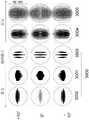
在五(5)个位置1101至1105处计算关于视网膜平面的离焦几何光斑分析;其中,列1101和1102代表位于视网膜前方-0.3mm和-0.1mm的视网膜位置;列1103表示位于视网膜上0mm的位置;并且列1104和1105表示位于视网膜后方+0.3mm和+0.1mm的视网膜位置。The out-of-focus geometric speckle analysis with respect to the retinal plane is calculated at five (5)
如可以观察到的,关于视网膜的离焦图像拼合图(montage)形成了具有椭圆形模糊图案的斯图姆氏类圆锥体或间距(1100),该斯图姆氏类圆锥体或间距包括切向平面(1101)和矢状平面(1103)以及最小弥散圆(1102)。在视网膜后方,椭圆形模糊图案(1104、1105)在尺寸上保持增大。在优选的配置中,接触透镜实施方式被规定成使得椭圆形焦点中的一个椭圆形焦点(切向的)位于视网膜前方而另一椭圆形焦点(矢状的)位于视网膜上。As can be observed, the montage of out-of-focus images with respect to the retina forms a Sturm's cone or interval (1100) with an elliptical blur pattern, which includes a tangent The sagittal plane (1101) and the sagittal plane (1103) and the circle of least confusion (1102). Behind the retina, the elliptical blur patterns (1104, 1105) remain increasing in size. In a preferred configuration, the contact lens embodiment is defined such that one of the elliptical foci (tangential) is located in front of the retina and the other elliptical focus (sagittal) is located on the retina.
位于视网膜前方的切向平面(1101)中的椭圆形模糊图案被称为子午线散光,而矢状平面(1103)中的椭圆形模糊图案被称为子午线矫正。在本公开的其他示例中,接触透镜实施方式可以被规定成使得两个椭圆形焦点(切向的和矢状的)都位于视网膜前方;在该示例中,矢状平面的位置配置成为眼睛至少部分地提供子午线矫正。在又一配置中,接触透镜实施方式可以被规定成使得椭圆形焦点中的一个椭圆形焦点(切向的)位于视网膜前方并且最小弥散圆位于视网膜上。此外,在这些所设想的配置中的每一者中,凭借配置到所设想的实施方式中的旋转对称的周边载体区,位于视网膜前方或位于视网膜上的散光的或环曲面的光学刺激由于眼睛上接触透镜旋转而随着自然眨眼动作发生变化,从而提供在时间上和空间上变化的光学信号。The elliptical blurring pattern in the tangential plane (1101) in front of the retina is called meridian astigmatism, and the elliptical blurring pattern in the sagittal plane (1103) is called meridional correction. In other examples of the present disclosure, contact lens embodiments may be specified such that both elliptical foci (tangential and sagittal) are located in front of the retina; in this example, the position of the sagittal plane is configured such that the eye is at least Partially provides meridian correction. In yet another configuration, the contact lens embodiment may be specified such that one of the elliptical foci (tangential) is located in front of the retina and the circle of least dispersion is located on the retina. Furthermore, in each of these envisaged configurations, by virtue of the rotationally symmetric peripheral carrier region configured into the envisaged embodiments, astigmatic or toric optical stimuli located in front of or on the retina are due to the eye The upper contact lens rotates to change with the natural blinking action, thereby providing a temporally and spatially varying optical signal.
图12图示了视网膜信号,该视网膜信号被描述为在时间上和空间上变化的点扩散函数的针对主子午线和垂直子午线的轴上的、离焦的、光学传递函数的模数;当具有可见波长(589nm)和0D聚散度的入射光入射在表1的-3D近视模型眼睛上时,该近视模型眼睛使用本文中所描述的接触透镜实施方式(示例#1)进行矫正。Figure 12 illustrates retinal signals described as the modulo of the temporally and spatially varying point spread functions for the axes of the principal and perpendicular meridians, out of focus, optical transfer functions; when having Incident light of visible wavelength (589 nm) and OD vergence was incident on the -3D myopic model eye of Table 1 corrected using the contact lens embodiment described herein (Example #1).
在该示例性的实施方式中,主子午线的光学传递函数的峰值位于视网膜平面处或视网膜平面稍前方,这为-3D近视眼睛提供至少部分的中央凹矫正或至少部分的子午线矫正。In this exemplary embodiment, the optical transfer function of the principal meridian has a peak at or slightly in front of the retinal plane, which provides at least partial foveal correction or at least partial meridional correction for -3D myopic eyes.
垂直子午线的光学传递函数的峰值在视网膜前方约0.38mm处,这提供了所诱发或引入的子午线停止信号。在此示例中,主子午线和垂直子午线的峰值分别与矢状平面和切向平面的椭圆模糊图案同义。The peak of the optical transfer function of the perpendicular meridian is approximately 0.38 mm in front of the retina, which provides the induced or induced meridian stop signal. In this example, the peaks of the principal and vertical meridians are synonymous with elliptical blur patterns in the sagittal and tangential planes, respectively.
在一些其他实施方式中,主子午线的光学传递函数的峰值可以在视网膜上并且在视网膜的前方不超过0.1mm处。在一些其他实施方式中,垂直子午线的光学传递函数的峰值可以在视网膜的前方约0.25mm、0.35mm、0.45mm或0.6mm处。在一些实施方式中,主子午线的峰值与垂直子午线的峰值之间的距离可以被优化以改善视觉性能,同时实现对光学停止信号有贡献的期望水平的诱发的子午线散光。In some other embodiments, the peak of the optical transfer function of the principal meridian may be on the retina and no more than 0.1 mm in front of the retina. In some other embodiments, the peak of the optical transfer function of the perpendicular meridian may be about 0.25 mm, 0.35 mm, 0.45 mm, or 0.6 mm in front of the retina. In some embodiments, the distance between the peak of the principal meridian and the peak of the vertical meridian can be optimized to improve visual performance while achieving a desired level of induced meridian astigmatism that contributes to the optical stop signal.
图13图示了示例性的实施方式(示例#2)的横跨8mm光区直径的二维焦度图(以D为单位)。透镜配置有-3D的球面焦度和+1.5DC的柱面焦度;当焦度轮廓被分解成两个主子午线时,一个主子午线(竖向实线,1301)的焦度约为-3D,而另一主子午线(水平虚线,1302)的焦度约为-1.5D。如本文中所描述的,横跨围绕光学中心、即围绕虚线和实线的交点的方位角的焦度变化遵循简单的余弦分布。FIG. 13 illustrates a two-dimensional power map (in D) across an 8 mm spot diameter for an exemplary embodiment (Example #2). The lens is configured with a spherical power of -3D and a cylindrical power of +1.5DC; when the power profile is decomposed into two principal meridians, one principal meridian (solid vertical line, 1301) has a power of approximately -3D , while the other principal meridian (dashed horizontal line, 1302) has a power of about -1.5D. As described herein, the power variation across the azimuth angle around the optical center, ie around the intersection of the dashed and solid lines, follows a simple cosine distribution.
透镜的沿着一个主子午线的球面焦度为-3D,这用于对表1中所描述的-3D近视模型眼睛进行至少部分的中央凹矫正或至少部分的子午线矫正,并且+1.5DC的散光的或环曲面的或柱面的焦度在模型眼睛的视网膜处提供所诱发的子午线停止信号。The spherical power of the lens along one principal meridian is -3D, which is used for at least partial foveal correction or at least partial meridian correction for the -3D myopic model eye described in Table 1, and +1.5DC of astigmatism The or toric or cylindrical power provides an induced meridian stop signal at the retina of the model eye.
图14图示了具有环曲面光区的现有技术的透镜的厚度轮廓。图14的现有技术的透镜具有棱镜压载稳定区。在仔细检查棱镜压载透镜的竖向子午线和水平子午线的径向厚度轮廓时,棱镜压载透镜是现有技术的具有-3.00/+1.50x90°的处方的典型透镜。Figure 14 illustrates the thickness profile of a prior art lens with a toric optical zone. The prior art lens of Figure 14 has a prismatic ballast stabilization zone. Upon careful examination of the radial thickness profiles of the vertical and horizontal meridians of the prismatic ballast lens, the prismatic ballast lens is a typical prior art lens with a prescription of -3.00/+1.50x90°.
水平部分(1401)是对称的,而竖向部分具有厚的下部(1402)部分和薄的上部(1403)部分,以在配合至眼睛时提供稳定的取向。竖向截面中陡峭的厚度曲率和水平子午线中的平坦的厚度曲率与所需的角膜散光相匹配,并且这提供了沿着任何子午线的良好视力。The horizontal portion (1401) is symmetrical, while the vertical portion has a thick lower (1402) portion and a thin upper (1403) portion to provide a stable orientation when fitted to the eye. The steep thickness curvature in the vertical section and the flat thickness curvature in the horizontal meridian match the desired corneal astigmatism, and this provides good vision along any meridian.
相反地,图15图示了本发明的示例性的实施方式(示例#2)的厚度轮廓。示出了接触透镜实施方式(示例#2)的沿着光区的陡峭部分和平坦部分的垂直子午线的两个厚度轮廓。图13中所描绘的接触透镜实施方式的球柱面焦度分布导致具有长轴(1501,平坦的子午线)和短轴(1502,陡峭的子午线)的椭圆形光学区。In contrast, Figure 15 illustrates the thickness profile of an exemplary embodiment of the present invention (Example #2). Two thickness profiles along the vertical meridian of the steep and flat portions of the optical zone are shown for a contact lens embodiment (Example #2). The sphero-cylindrical power profile of the contact lens embodiment depicted in Figure 13 results in an elliptical optical zone with a major axis (1501, a flat meridian) and a minor axis (1502, a steep meridian).
在该示例性的实施方式中,短轴(1502,陡峭的子午线)与非光学周边载体区(1503)之间的区导致阶梯式过渡区或混合区(1504)。在该示例性的实施方式中,横跨示例性实施方式(示例#2)的主子午线的焦度变化被设计为是最小的(即平坦的焦度轮廓)。In this exemplary embodiment, the region between the minor axis (1502, the steep meridian) and the non-optical peripheral carrier region (1503) results in a stepped transition or mixing region (1504). In this exemplary embodiment, the power variation across the principal meridian of the exemplary embodiment (Example #2) is designed to be minimal (ie, a flat power profile).
如图15中可以看出,透镜的周边非光学区具有基本上旋转对称的载体区。这种设计促进了接触透镜实施方式(示例#2)由于因上眼睑和下眼睑的组合动作促成的自然眨眼而在光学中心上或者关于光学中心附近基本上自由地旋转,这又导致由光学区施加的散光刺激随眨眼而变化,进而导致在时间上和空间上变化的刺激,以降低近视佩戴者的近视进展的速率;其中,减小眼睛生长速率的方向性提示和功效随时间基本上保持一致。As can be seen in Figure 15, the peripheral non-optical zone of the lens has a substantially rotationally symmetric carrier zone. This design facilitates substantially free rotation of the contact lens embodiment (Example #2) on or about the optical center due to the natural blink caused by the combined action of the upper and lower eyelids, which in turn results in a Applied astigmatic stimuli vary with blinking, resulting in temporally and spatially varying stimuli to reduce the rate of myopia progression in myopic wearers; wherein the directional cues and efficacy of reducing the rate of eye growth remain substantially over time Consistent.
当聚散度为0D的可见波长(589nm)的入射光入射在表1的使用示例性的实施方式(示例#2)进行矫正的近视眼睛上时在视网膜平面处合成的轴上的在时间上和空间上变化的点扩散函数在图16中图示,其中,透镜的主子午线位于0°(1601)、45°(1602)、90°(1603)和135°(1604)处。可以注意到,当与使用示例1(图10)所获得的结果相比较时,示例2(图16)中在视网膜处捕获的轴上点扩散函数的长度增加,这是由于该接触透镜实施方式(示例#2)的柱面焦度增加。Temporal on axis synthesized at retinal plane when incident light of visible wavelength (589 nm) with vergence 0D is incident on the myopic eye of Table 1 corrected using the exemplary embodiment (Example #2) The and spatially varying point spread functions are illustrated in Figure 16, where the principal meridian of the lens is located at 0° (1601), 45° (1602), 90° (1603) and 135° (1604). It can be noted that the length of the on-axis point spread function captured at the retina in Example 2 (Figure 16) increases when compared to the results obtained using Example 1 (Figure 10) due to this contact lens implementation The cylindrical power of (Example #2) increases.
示例性的实施方式(示例#2)的旋转对称周边载体区有利于被描述为视网膜上的矢状平面的点扩散函数的散光刺激由于接触透镜旋转而随着自然眨眼动作发生变化,从而向眼睛提供在时间上和空间上变化的信号。The rotationally symmetric peripheral carrier region of the exemplary embodiment (Example #2) facilitates an astigmatic stimulus, which is described as the point spread function of the sagittal plane on the retina, that changes with natural blinking due to contact lens rotation to the eye. Provides a signal that varies in time and space.
图17图示了广角的(即,±10°的视野)、在时间上和空间上变化的信号,其中,接触透镜实施方式(示例#2)的主子午线围绕光学中心旋转0°、45°、90°和135°,以模拟接触透镜随时间的旋转。图17的离焦几何光斑图表示光学停止信号的时间积分,该光学停止信号的时间积分是通过对当接触透镜实施方式配合在-3D近视模型眼睛上并且进一步以4种不同的配置旋转(旋转0°、45°、90°和135°)进而模拟所述接触透镜在眼睛上的旋转从而产生在空间上和时间上变化的光学停止信号时合成的响应进行积分而获得的。Figure 17 illustrates a wide angle (ie, ±10° field of view), temporally and spatially varying signal where the principal meridian of a contact lens embodiment (Example #2) is rotated 0°, 45° about the optical center , 90°, and 135° to simulate the rotation of the contact lens over time. The out-of-focus geometric spot diagram of Figure 17 represents the time integral of the optical stop signal obtained by comparing the time integral of the optical stop signal when the contact lens embodiment is fitted on a -3D myopia model eye and further rotated in 4 different configurations (rotational 0°, 45°, 90°, and 135°) were then obtained by integrating the synthesized responses when simulating the rotation of the contact lens on the eye resulting in a spatially and temporally varying optical stop signal.
在五(5)个位置1701至1705处计算关于视网膜平面的离焦几何光斑分析;其中,列1701和列1702表示位于视网膜前方-0.3mm和-0.15mm的视网膜位置;列1703表示位于视网膜上0mm的位置;并且列1704和列1705表示位于视网膜后方+0.3mm和+0.15mm的视网膜位置。The out-of-focus geometric speckle analysis with respect to the retinal plane is calculated at five (5)
可以看出,关于视网膜的离焦图像拼合图形成了具有椭圆形模糊图案的斯图姆氏类圆锥体或间距(1700),该斯图姆氏类圆锥体或间距包括切向平面(1701)和矢状平面(1703)以及最小弥散圆(1702)。在视网膜后方,椭圆形模糊图案(1704、1705)的尺寸不断增加。在优选的配置中,接触透镜实施方式被规定成使得椭圆形焦点中的一个椭圆形焦点(切向的)位于视网膜的前方而另一椭圆形焦点(矢状的)位于视网膜上。It can be seen that the out-of-focus image patch for the retina forms a Sturm's cone or interval (1700) with an elliptical blur pattern that includes a tangential plane (1701) and sagittal plane (1703) and minimum circle of confusion (1702). Behind the retina, the elliptical blur pattern (1704, 1705) increases in size. In a preferred configuration, the contact lens embodiment is defined such that one of the elliptical foci (tangential) is located in front of the retina and the other elliptical focus (sagittal) is located on the retina.
当与示例1(图11)相比较时,通过示例2(图17)获得的离焦图像中所描绘的矢状平面和切向平面的长度增加,这是由于该透镜实施方式(示例#2)的柱面焦度增加。每个光斑图的比例被标注为300μm。The length of the sagittal and tangential planes depicted in the out-of-focus images obtained by Example 2 (Figure 17) increases when compared to Example 1 (Figure 11) due to this lens implementation (Example #2 ) the cylindrical power increases. The scale of each spot pattern is marked as 300 μm.
在本公开的其他示例中,接触透镜实施方式可以被规定为使得两个椭圆形焦点(切向的和矢状的)均位于视网膜的前方。在又一配置中,接触透镜实施方式可以被规定为使得椭圆形焦点中的一个椭圆形焦点(切向的)位于视网膜的前方并且最小弥散圆位于视网膜上。In other examples of the present disclosure, contact lens embodiments may be specified such that both elliptical foci (tangential and sagittal) are located in front of the retina. In yet another configuration, the contact lens embodiment may be specified such that one of the elliptical foci (tangential) is located in front of the retina and the circle of least confusion is located on the retina.
此外,在这些所设想的配置中的每一者中,凭借配置到所设想的实施方式中的旋转对称的周边载体区,位于视网膜前方或位于视网膜上的散光的或环曲面的光学刺激由于接触透镜在眼睛上的旋转而随自然眨眼动作发生变化,从而提供在时间上和空间上变化的光学信号。Furthermore, in each of these envisaged configurations, by virtue of the rotationally symmetric peripheral carrier region configured into the envisaged embodiments, astigmatic or toric optical stimuli located in front of or on the retina due to contact Rotation of the lens on the eye follows the natural blinking action, providing an optical signal that varies in time and space.
图18图示了视网膜信号,该视网膜信号被描述为在时间上和空间上变化的点扩散函数的主子午线和垂直子午线的轴上的、离焦的、光学传递函数的模数;当具有可见波长(589nm)和0D聚散度的入射光入射在表1的-3D近视模型眼睛上时,该近视模型眼睛用本文中所描述的接触透镜实施方式(示例#2)进行矫正。Figure 18 illustrates retinal signals described as temporally and spatially varying point spread functions on the axes of the principal and perpendicular meridians, out of focus, and the modulus of the optical transfer function; when with visible Incident light of wavelength (589 nm) and OD vergence was incident on the -3D myopic model eye of Table 1, which was corrected with the contact lens embodiment described herein (Example #2).
在该示例性的实施方式中,主子午线的光学传递函数的峰值位于视网膜平面处或视网膜平面稍前方,这为-3D近视眼睛提供至少部分的中央凹矫正或至少部分的子午线矫正。In this exemplary embodiment, the optical transfer function of the principal meridian has a peak at or slightly in front of the retinal plane, which provides at least partial foveal correction or at least partial meridional correction for -3D myopic eyes.
垂直子午线的光学传递函数的峰值在视网膜前方约0.64mm处,这提供了所诱发或引入的子午线停止信号。在此示例中,主子午线和垂直子午线的峰值分别与矢状平面和切向平面的椭圆形模糊图案同义。The peak of the optical transfer function of the perpendicular meridian is approximately 0.64 mm in front of the retina, which provides the induced or induced meridian stop signal. In this example, the peaks of the principal and vertical meridians are synonymous with elliptical blur patterns in the sagittal and tangential planes, respectively.
在一些其他实施方式中,主子午线的光学传递函数的峰值可以在视网膜上并且在视网膜的前方不超过0.1mm处。在一些其他实施方式中,垂直子午线的光学传递函数的峰值可以在视网膜的前方约0.25mm、0.35mm、0.45mm或0.6mm处。在一些实施方式中,主子午线的峰值与垂直子午线的峰值之间的距离可以被优化以改善视觉性能,同时实现对光学停止信号有贡献的期望水平的诱发的子午线散光。In some other embodiments, the peak of the optical transfer function of the principal meridian may be on the retina and no more than 0.1 mm in front of the retina. In some other embodiments, the peak of the optical transfer function of the perpendicular meridian may be about 0.25 mm, 0.35 mm, 0.45 mm, or 0.6 mm in front of the retina. In some embodiments, the distance between the peak of the principal meridian and the peak of the vertical meridian can be optimized to improve visual performance while achieving a desired level of induced meridian astigmatism that contributes to the optical stop signal.
图19图示了示例性的实施方式(示例#3)的横跨8mm光区直径的二维焦度图(以D为单位)。透镜配置有-3D的球面焦度和+1.5DC的柱面焦度;除了球柱面焦度分布之外,该透镜还配置为在光学区的端部处具有限定的-0.75D的主球面像差。Figure 19 illustrates a two-dimensional power plot (in D) across an 8 mm spot diameter for an exemplary embodiment (Example #3). The lens is configured with a spherical power of -3D and a cylindrical power of +1.5DC; in addition to the sphero-cylindrical power distribution, the lens is configured with a defined principal spherical surface of -0.75D at the end of the optic zone aberrations.
当焦度图被分解成两个主子午线时,一个主子午线(竖向实线,1901)的焦度约为-3D,其中上面所限定的负的主球面像差的大小被限定在整个光区上;并且另一主子午线(水平虚线,1902)的焦度约为-1.5D,其中上面所限定的负的主球面像差的大小被限定在整个光区上。如本文中所描述的,横跨围绕光学中心、即围绕虚线和实线的交点的方位角的焦度变化遵循复杂的余弦分布。When the power map is decomposed into two principal meridians, one principal meridian (solid vertical line, 1901) has a power of about -3D, where the magnitude of the negative principal spherical aberration defined above is limited across the entire light and the power of the other principal meridian (dashed horizontal line, 1902) is about -1.5D, where the magnitude of the negative principal spherical aberration defined above is defined over the entire optical area. As described herein, the power variation across the azimuth angle around the optical center, ie around the intersection of the dashed and solid lines, follows a complex cosine distribution.
在一些示例性的实施方式中,基本上非对称的焦度分布使用由以下表达式描述的焦度分布函数来表示:球面+方位角分量,其中,球面是指用以矫正眼睛的距离球面处方焦度,焦度分布函数的方位角分量被描述为Ca*cos(mθ),其中,Ca为方位角系数,m为1与6之间的整数,并且Theta(θ)为光区的给定点的方位角角度。In some exemplary embodiments, a substantially asymmetric power distribution is represented using a power distribution function described by the following expression: Spherical + Azimuth component, where Spherical refers to the distance spherical prescription used to correct the eye Power, the azimuth component of the power distribution function is described as Ca *cos(mθ), where Ca is the azimuth coefficient, m is an integer between 1 and 6, and Theta(θ) is the The azimuth angle of the given point.
在一些其他示例性的实施方式中,基本上非对称的焦度分布使用由以下表达式描述的焦度分布函数来表示:球面+(径向分量)*(方位角分量),其中,球面是指用以矫正近视眼睛的距离球面处方焦度,焦度分布函数的径向分量被描述为Cr*ρ,其中,Cr是膨胀系数,并且Rho(ρ)是归一化的径向坐标(ρ0/ρ最大);焦度分布函数的方位角分量被描述为Ca*cos(mθ),其中,m可以是1与6之间的任何整数,并且Theta(θ)是方位角角度,其中,Rho(ρ0)是给定点的径向坐标,其中,ρ最大是视区的最大径向坐标或半径。示例#3的接触透镜实施方式被配置成为表1中所描述的-3D近视模型眼睛提供至少部分的中央凹矫正或至少部分的子午线矫正,并且基本上以光轴为中心的非对称的焦度分布(其被限定为关于方位角的复杂的余弦分布)在模型眼睛的视网膜处提供诱发的子午线停止信号。在本公开的其他实施方式中,改变主球面像差的其他大小例如在接触透镜的整个光区上限定的-0.5D、-1D、-1.25D可能是更期望的。在本公开的一些其他实施方式中,正球面像差的期望大小可以在光学区的小区域上配置为例如5mm、6mm或7mm。In some other exemplary embodiments, a substantially asymmetric power distribution is represented using a power distribution function described by the following expression: sphere+(radial component)*(azimuth component), where sphere is Refers to the distance spherical prescription power used to correct myopic eyes, the radial component of the power distribution function is described as Cr *ρ, where Cr is the expansion coefficient and Rho(ρ) is the normalized radial coordinate (ρ0 /ρmax ); the azimuthal component of the power distribution function is described as Ca *cos(mθ), where m can be any integer between 1 and 6, and Theta(θ) is the azimuth angle , where Rho(ρ0 ) is the radial coordinate of a given point, where ρmax is themaximum radial coordinate or radius of the viewport. The contact lens embodiment of
图20图示了本发明的示例性实施方式(示例#3)的横截面厚度轮廓。对于接触透镜示例#3,示出了沿着光区的陡峭部分(2001)和平坦部分(2002)的垂直子午线的两个厚度轮廓。在该示例性的实施方式中,沿着图19中所描绘的接触透镜实施方式的方位角方向限定的非对称的焦度分布导致具有长轴(2002,平坦的子午线)和短轴(2001,陡峭的子午线)的椭圆形光学区,该非对称的焦度分布可以表示为围绕光学中心的复杂的余弦分布。Figure 20 illustrates the cross-sectional thickness profile of an exemplary embodiment of the present invention (Example #3). For Contact
在该示例性的实施方式中,短轴(2001,陡峭的子午线)与非光学周边载体区(2003)之间的区产生阶梯式过渡区或混合区(2004)。如图20中可以看出,透镜的周边非光学区具有基本上旋转对称的载体区。这种设计促进了接触透镜实施方式(示例#3)由于因上眼睑和下眼睑的组合动作促成的自然眨眼而在光学中心上或关于光学中心附近基本上自由地旋转,这又导致由光学区施加的散光刺激随眨眼而变化,进而导致在时间上和空间上变化的刺激,以降低近视佩戴者的进展速率,其中,减小眼睛生长进展的方向性提示和功效随时间基本上保持一致。In this exemplary embodiment, the region between the short axis (2001, the steep meridian) and the non-optical peripheral carrier region (2003) produces a stepped transition or mixing region (2004). As can be seen in Figure 20, the peripheral non-optical zone of the lens has a substantially rotationally symmetric carrier zone. This design facilitates the substantially free rotation of the contact lens embodiment (Example #3) on or about the optical center due to the natural blinking caused by the combined action of the upper and lower eyelids, which in turn results in a The applied astigmatic stimuli varied with blinking, resulting in temporally and spatially varying stimuli to reduce the rate of progression in myopic wearers, wherein the directional cues and efficacy of reducing eye growth progression remained substantially consistent over time.
当聚散度为0D的可见波长(589nm)的入射光入射在表1的使用示例性的实施方式(示例#3)进行矫正的近视眼睛上时在视网膜平面处合成的轴上的在时间上和空间上变化的点扩散函数在图21中图示,其中,透镜的主子午线位于0°(2101)、45°(2202)、90°(2203)和135°(2204)处。Temporal on axis synthesized at retinal plane when incident light of visible wavelength (589 nm) with vergence 0D is incident on the myopic eye of Table 1 corrected using the exemplary embodiment (Example #3) The and spatially varying point spread functions are illustrated in Figure 21, where the principal meridian of the lens is located at 0° (2101), 45° (2202), 90° (2203) and 135° (2204).
可以注意到,当与使用示例1和示例2(图10和图16)所获得的结果相比较时,示例3(图21)中在视网膜处捕获的轴上点扩散函数的长度减小,这是由于在该接触透镜实施方式(示例#3)中引入了负的主球面像差。It can be noted that the length of the on-axis point spread function captured at the retina in Example 3 (Figure 21) decreases when compared to the results obtained using Example 1 and Example 2 (Figure 10 and Figure 16), which This is due to the introduction of negative principal spherical aberration in this contact lens embodiment (Example #3).
示例性的实施方式(示例#3)的旋转对称周边载体区有利于被描述为视网膜上的矢状平面的点扩散函数的散光刺激由于接触透镜旋转而随着自然眨眼动作发生变化,从而为眼睛提供在时间上和空间上变化的信号。The rotationally symmetric peripheral carrier region of the exemplary embodiment (Example #3) facilitates astigmatic stimulation, which is described as the point spread function of the sagittal plane on the retina, as a function of natural blinking due to contact lens rotation, thereby providing an eye Provides a signal that varies in time and space.
图22图示了广角的(即,±10°的视野)、在时间上和空间上变化的信号,其中,接触透镜实施方式(示例#3)的主子午线围绕光学中心旋转了0°、45°、90°和135°,以模拟接触透镜随时间的旋转。Figure 22 illustrates a wide angle (ie, ±10° field of view), temporally and spatially varying signal where the principal meridian of a contact lens embodiment (Example #3) is rotated 0°, 45° about the optical center °, 90°, and 135° to simulate the rotation of the contact lens over time.
图22的离焦几何光斑图表示光学停止信号的时间积分,该光学停止信号的时间积分是通过对当接触透镜实施方式配合在-3D近视模型眼睛上并且进一步以4种不同的配置旋转(旋转0°、45°、90°和135°)进而模拟所述接触透镜在眼睛上的旋转从而产生在空间上和时间上变化的光学停止信号时合成的响应进行积分而获得的。The out-of-focus geometric spot diagram of FIG. 22 represents the time integral of the optical stop signal obtained by comparing the time integral of the optical stop signal when the contact lens embodiment is fitted on a -3D myopia model eye and further rotated in 4 different configurations (rotational 0°, 45°, 90°, and 135°) were then obtained by integrating the synthesized responses when simulating the rotation of the contact lens on the eye resulting in a spatially and temporally varying optical stop signal.
在五(5)个位置2201至2205处计算关于视网膜平面的离焦几何光斑分析;其中,列2201和列2202表示位于视网膜的前方-0.3mm和-0.15mm的视网膜位置;列2203表示位于视网膜上0mm的位置;并且列2204和列2205表示位于视网膜后方+0.3mm和+0.15mm的视网膜位置。The out-of-focus geometric speckle analysis with respect to the retinal plane is computed at five (5)
可以看出,关于视网膜的离焦图像拼合图形成了具有椭圆的模糊图案的斯图姆氏类圆锥体或间距(2200),该斯图姆氏类圆锥体或间距包括切向平面(2201)和矢状平面(2203)以及最小弥散圆(2202)。在视网膜后方,椭圆的模糊图案(2204、2205)的尺寸不断增加。在优选的配置中,接触透镜实施方式被规定成使得椭圆形焦点中的一个椭圆形焦点(切向的)位于视网膜的前方而另一椭圆形焦点(矢状的)位于视网膜上。It can be seen that the out-of-focus image mosaic for the retina forms a Sturm cone or interval with an elliptical blur pattern (2200) that includes a tangential plane (2201) and sagittal plane (2203) and minimum circle of confusion (2202). Behind the retina, the elliptical blur pattern (2204, 2205) increases in size. In a preferred configuration, the contact lens embodiment is defined such that one of the elliptical foci (tangential) is located in front of the retina and the other elliptical focus (sagittal) is located on the retina.
当与示例1和示例2(图11和图17)相比较时,通过示例2(图17)获得的离焦图像中所描绘的矢状平面和切向平面的长度减小,这是因为该透镜实施方式(示例#2)中引入负的主球面像差。每个光斑图的比例被标注为300μm。在本公开的其他示例中,接触透镜实施方式可以规定为使得两个椭圆形焦点(切向的和矢状的)均位于视网膜的前方。在又一配置中,接触透镜实施方式可以规定为使得椭圆形焦点中的一个椭圆形焦点(切向的)位于视网膜的前方并且最小弥散圆位于视网膜上。此外,在这些所设想的配置中的每一者中,凭借配置到所设想的实施方式中的旋转对称的周边载体区,位于视网膜的前方或位于视网膜上的非对称的模糊刺激由于接触透镜在眼睛上的旋转而随着自然眨眼动作发生变化,从而提供了在时间上和空间上变化的光学信号。The length of the sagittal and tangential planes depicted in the out-of-focus images obtained by Negative principal spherical aberration is introduced in the lens embodiment (Example #2). The scale of each spot pattern is marked as 300 μm. In other examples of the present disclosure, contact lens embodiments may be specified such that both elliptical foci (tangential and sagittal) are located in front of the retina. In yet another configuration, the contact lens embodiment may be specified such that one of the elliptical foci (tangential) is located in front of the retina and the circle of least dispersion is located on the retina. Furthermore, in each of these envisaged configurations, by virtue of the rotationally symmetric peripheral carrier region configured into the envisaged embodiments, asymmetrical blurred stimuli located in front of or on the retina due to the contact lens in the The rotation on the eye changes with the natural blinking action, providing optical signals that vary in time and space.
图23图示了被描述为在时间上和空间上变化的点扩散函数的针对主子午线和垂直子午线的轴上的、离焦的、光学传递函数的模数的视网膜信号;当具有可见波长(589nm)和0D聚散度的入射光入射在表1的-3D近视模型眼睛上时,该近视模型眼睛使用本文中所描述的接触透镜实施方式(示例#3)进行矫正。Figure 23 illustrates retinal signals for on-axis, out-of-focus, modulus of optical transfer functions for the axes of the principal and perpendicular meridians, described as temporally and spatially varying point spread functions; when having visible wavelengths ( 589 nm) and 0D vergence incident light on the -3D myopic model eye of Table 1 corrected using the contact lens embodiment described herein (Example #3).
在该示例性的实施方式中,主子午线的光学传递函数的峰值位于视网膜平面处或视网膜平面稍前方,这为-3D近视眼睛提供至少部分的中央凹矫正或者至少部分的子午线矫正。垂直子午线的光学传递函数的峰值在视网膜前方约0.42mm处,这提供了所诱发或引入的子午线的停止信号。在此示例中,主子午线和垂直子午线的峰值分别与矢状平面和切向平面的椭圆模糊图案同义。In this exemplary embodiment, the optical transfer function of the principal meridian has a peak at or slightly in front of the retinal plane, which provides at least partial foveal correction or at least partial meridian correction for -3D myopic eyes. The peak of the optical transfer function of the perpendicular meridian is approximately 0.42 mm in front of the retina, which provides a stop signal for the induced or introduced meridian. In this example, the peaks of the principal and vertical meridians are synonymous with elliptical blur patterns in the sagittal and tangential planes, respectively.
在一些其他实施方式中,主子午线的光学传递函数的峰值可以在视网膜上并且在视网膜的前方不超过0.1mm处。在一些其他实施方式中,垂直子午线的光学传递函数的峰值可以在视网膜的前方约0.25mm、0.35mm、0.45mm或0.6mm处。在一些实施方式中,主子午线的峰值与垂直子午线的峰值之间的距离可以被优化以改善视觉性能,同时实现对光学停止信号有贡献的期望水平的诱发的子午线散光。In some other embodiments, the peak of the optical transfer function of the principal meridian may be on the retina and no more than 0.1 mm in front of the retina. In some other embodiments, the peak of the optical transfer function of the perpendicular meridian may be about 0.25 mm, 0.35 mm, 0.45 mm, or 0.6 mm in front of the retina. In some embodiments, the distance between the peak of the principal meridian and the peak of the vertical meridian can be optimized to improve visual performance while achieving a desired level of induced meridian astigmatism that contributes to the optical stop signal.
图24图示了示例性的实施方式(示例#4)的横跨8mm光区直径的二维焦度图(以D为单位)。透镜配置有-3D的球面焦度和+1.5DC的柱面焦度;除了球柱面焦度分布之外,该透镜配置成在光学区的端部处具有限定的+0.75D的主球面像差。当焦度图分解成两个主子午线时,一个主子午线(竖向实线,2401)的焦度约为-3D,其中上面所限定的正的主球面像差的大小被限定在整个光区上;并且另一主子午线(水平虚线,2402)的焦度约为-1.5D,其中上面所限定的正的主球面像差的大小被限定在整个光区上。如本文中所描述的,横跨围绕光学中心、即围绕虚线和实线的交点的方位角的焦度变化遵循复杂的余弦分布。Figure 24 illustrates a two-dimensional power map (in D) across an 8 mm spot diameter for an exemplary embodiment (Example #4). The lens is configured with a spherical power of -3D and a cylindrical power of +1.5DC; in addition to the sphero-cylindrical power distribution, the lens is configured to have a defined principal spherical image of +0.75D at the end of the optic zone Difference. When the power map is decomposed into two principal meridians, one principal meridian (solid vertical line, 2401) has a power of about -3D, where the magnitude of the positive principal spherical aberration defined above is limited to the entire optical area and the power of the other principal meridian (dashed horizontal line, 2402) is about -1.5D, where the magnitude of the positive principal spherical aberration defined above is defined over the entire optical zone. As described herein, the power variation across the azimuth angle around the optical center, ie around the intersection of the dashed and solid lines, follows a complex cosine distribution.
在一些示例性的实施方式中,基本上非对称的焦度分布使用下述焦度分布函数来表示:该焦度分布函数至少部分地使用具有通用表达式(n、m)的第一类贝塞尔循环函数的项中的至少一个或更多个项来描述;其中,当n取值为1、2、3并且m取值为±2时,获得贝塞尔循环函数的项中的至少一个或更多个项。在一些其他示例性的实施方式中,方位角焦度分布函数呈cos2(mθ)的形式,其中,m是1与6之间的整数,包括1和6。In some exemplary embodiments, a substantially asymmetric power distribution is represented using a power distribution function that uses, at least in part, a first class of shellfish having the general expression (n, m). Described by at least one or more of the terms of the Bessel cycle function; wherein, when n takes the value of 1, 2, 3 and m takes the value of ±2, at least one of the terms of the Bessel cycle function is obtained one or more items. In some other exemplary embodiments, the azimuthal power distribution function is in the form of cos2 (mθ), where m is an integer between 1 and 6, inclusive.
示例#4的接触透镜实施方式被配置成为表1中所描述的-3D近视模型眼睛提供至少部分的中央凹矫正或至少部分的子午线矫正,并且关于光轴的非对称焦度分布(其被限定为关于方位角的复杂的余弦分布)在模型眼睛的视网膜处提供了诱发的子午线停止信号。The contact lens embodiment of
在本公开的其他实施方式中,改变主球面像差的其他大小,例如在接触透镜的整个光区上限定的+0.5D、+1D、+1.25D可能是更期望的。在本公开的一些其他实施方式中,正球面像差的期望大小可以在光学区的小区域上配置为例如5mm、6mm或7mm。In other embodiments of the present disclosure, it may be more desirable to vary other magnitudes of the principal spherical aberration, such as +0.5D, +1D, +1.25D defined over the entire optical area of the contact lens. In some other embodiments of the present disclosure, the desired magnitude of positive spherical aberration may be configured, eg, 5 mm, 6 mm, or 7 mm over a small area of the optical zone.
图25图示了本发明的示例性的实施方式(示例#4)的横截面厚度轮廓。对于接触透镜示例#4,示出了沿着光区的陡峭部分(2501)和平坦部分(2502)的垂直子午线的两个厚度轮廓。在该示例性的实施方式中,沿着图24中所描绘的接触透镜实施方式的方位角方向限定的非对称的焦度分布——该非对称的焦度分布可以表示为围绕光学中心的复杂的余弦分布——导致具有长轴(2502,平坦的子午线)和短轴(2501,陡峭的子午线)的椭圆形光学区。在该示例性的实施方式中,短轴(2501,陡峭的子午线)与非光学周边载体区(2503)之间的区产生阶梯式过渡区或混合区(2504)。Figure 25 illustrates the cross-sectional thickness profile of an exemplary embodiment of the present invention (Example #4). For Contact
如图25中可以看出,透镜的周边非光学区具有基本上旋转对称的载体区。这种设计促进了接触透镜实施方式(示例#4)由于因上眼睑和下眼睑的组合动作促成的自然眨眼而在光学中心上或关于该光学中心附近基本上自由地旋转,这又导致由光学区施加的非对称的刺激随眨眼而变化,进而导致在时间上和空间上变化的刺激,以降低近视佩戴者的进展速率,其中,减小眼睛生长进展的方向性提示和功效随时间基本上保持一致。As can be seen in Figure 25, the peripheral non-optical zone of the lens has a substantially rotationally symmetric carrier zone. This design facilitates substantially free rotation of the contact lens embodiment (Example #4) on or about the optical center due to the natural blink caused by the combined action of the upper and lower eyelids, which in turn results in The asymmetric stimulus applied by the area varies with blinking, resulting in temporally and spatially varying stimuli to reduce the rate of progression in myopic wearers, wherein the directional cues and efficacy of reducing eye growth progression substantially over time be consistent.
当聚散度为0D的可见波长(589nm)的入射光入射在表1的使用示例性的实施方式(示例#4)进行矫正的近视眼睛上时在视网膜平面处合成的轴上的在时间上和空间上变化的点扩散函数在图26中图示,其中,透镜的主子午线位于0°(2601)、45°(2602)、90°(2603)和135°(2604)处。Temporal time on the axis synthesized at the retinal plane when incident light of visible wavelength (589 nm) with vergence 0D is incident on the myopic eye of Table 1 corrected using the exemplary embodiment (Example #4) The and spatially varying point spread functions are illustrated in Figure 26, where the principal meridian of the lens is located at 0° (2601), 45° (2602), 90° (2603) and 135° (2604).
可以注意到,当与使用示例3(图21)所获得的结果相比较时,示例4(图26)中在视网膜处捕获的轴上点扩散函数略微清晰,这是由于在该接触透镜实施方式(示例#4)中引入了正的主球面像差。示例性的实施方式(示例#4)的旋转对称周边载体区有利于被描绘为视网膜上的矢状平面的点扩散函数的散光刺激由于接触透镜旋转而随着自然眨眼动作发生变化,从而为眼睛提供在时间上和空间上变化的信号。It can be noted that the on-axis point spread function captured at the retina in Example 4 (FIG. 26) is slightly sharper when compared to the results obtained using Example 3 (FIG. 21), due to the fact that in this contact lens implementation A positive principal spherical aberration is introduced in (Example #4). The rotationally symmetric peripheral carrier region of the exemplary embodiment (Example #4) facilitates astigmatic stimulation, which is depicted as the point spread function of the sagittal plane on the retina, as a function of natural blinking action due to contact lens rotation, thereby providing an eye Provides a signal that varies in time and space.
图27图示了广角的(即,±10°的视野)、在时间上和空间上变化的信号,其中,接触透镜实施方式(示例#4)的主子午线围绕光学中心旋转了0°、45°、90°和135°,以模拟接触透镜随时间的旋转。图27的离焦几何光斑图表示光学停止信号的时间积分,该光学停止信号的时间积分是通过对当接触透镜实施方式配合在-3D近视模型眼睛上并且进一步以4种不同的配置旋转(旋转0°、45°、90°和135°)进而模拟所述接触透镜在眼睛上的旋转从而产生在空间上和时间上变化的光学停止信号时合成的响应进行积分而获得的。在五(5)个位置2701至2705处计算关于视网膜平面的离焦几何光斑分析;其中,列2701和列2702表示位于视网膜的前方-0.3mm和-0.15mm的视网膜位置;列2703表示位于视网膜上0mm的位置;并且列2704和列2705表示位于视网膜后方+0.3mm和+0.15mm的视网膜位置。可以看出,关于视网膜的离焦图像拼合图形成了具有椭圆的模糊图案的斯图姆氏类圆锥体或间距(2700),该斯图姆氏类圆锥体或间距包括切向平面(2701)和矢状平面(2703)以及最小弥散圆(2702)。在视网膜后方,椭圆的模糊图案(2704、2705)的尺寸不断增加。在优选的配置中,接触透镜实施方式被规定成使得椭圆形焦点中的一个椭圆形焦点(切向的)位于视网膜的前方而另一椭圆形焦点(矢状的)位于视网膜上。当与示例2(图17)相比较时,示例4(图27)中的离焦图像稍微增大,这是因为该透镜的负的球面像差。每个光斑图的比例被标注为300μm。Figure 27 illustrates a wide angle (ie, ±10° field of view), temporally and spatially varying signal where the principal meridian of the contact lens embodiment (Example #4) is rotated 0°, 45° about the optical center °, 90°, and 135° to simulate the rotation of the contact lens over time. The out-of-focus geometric spot diagram of FIG. 27 represents the time integral of the optical stop signal obtained by comparing the time integral of the optical stop signal when the contact lens embodiment is fitted on a -3D myopia model eye and further rotated in 4 different configurations (rotational 0°, 45°, 90°, and 135°) were then obtained by integrating the synthesized responses when simulating the rotation of the contact lens on the eye resulting in a spatially and temporally varying optical stop signal. The out-of-focus geometric speckle analysis with respect to the retinal plane is calculated at five (5)
在本公开的其他示例中,接触透镜实施方式可以规定为使得两个椭圆形焦点(切向的和矢状的)均位于视网膜的前方。在又一配置中,接触透镜实施方式可以规定为使得椭圆形焦点中的一个椭圆形焦点(切向的)位于视网膜的前方并且最小弥散圆位于视网膜上。此外,在这些所设想的配置中的每一者中,凭借配置到所设想的实施方式中的旋转对称的周边载体区,位于视网膜的前方或位于视网膜上的非对称的模糊刺激由于接触透镜在眼睛上的旋转而随着自然眨眼动作发生变化,从而提供了在时间上和空间上变化的光学信号。In other examples of the present disclosure, contact lens embodiments may be specified such that both elliptical foci (tangential and sagittal) are located in front of the retina. In yet another configuration, the contact lens embodiment may be specified such that one of the elliptical foci (tangential) is located in front of the retina and the circle of least dispersion is located on the retina. Furthermore, in each of these envisaged configurations, by virtue of the rotationally symmetric peripheral carrier region configured into the envisaged embodiments, asymmetrical blurred stimuli located in front of or on the retina due to the contact lens in the The rotation on the eye changes with the natural blinking action, providing optical signals that vary in time and space.
图28图示了被描述为在时间上和空间上变化的点扩散函数的针对主子午线和垂直子午线的轴上的、离焦的、光学传递函数的模数的视网膜信号;当具有可见波长(589nm)和0D聚散度的入射光入射在表1的-3D近视模型眼睛上时,该近视模型眼睛使用本文中所描述的接触透镜实施方式(示例#4)进行矫正。在该示例性的实施方式中,主子午线的光学传递函数的峰值位于视网膜平面处或视网膜平面稍前方,这为-3D近视眼睛提供至少部分的中央凹矫正或者至少部分的子午线矫正。垂直子午线的光学传递函数的峰值在视网膜前方约0.45mm处,这提供了所诱发或引入的子午线的停止信号。在该示例中,主子午线和垂直子午线的峰值分别与矢状平面和切向平面的椭圆模糊图案同义。在一些其他实施方式中,主子午线的光学传递函数的峰值可以在视网膜上并且在视网膜前方不超过0.1mm处。在一些其他实施方式中,垂直子午线的光学传递函数的峰值可以在视网膜的前方约0.25mm、0.35mm、0.45mm或0.6mm处。在一些实施方式中,主子午线的峰值与垂直子午线的峰值之间的距离可以被优化以改善视觉性能,同时实现对光学停止信号有贡献的期望水平的诱发的子午线散光。当聚散度为0D的可见波长(589nm)的入射光入射在表1的使用示例性的实施方式(示例#2)进行矫正的近视眼睛上时,在视网膜平面处通过透镜沿着x轴偏心0.75mm(2901)和-0.75mm(2902)以及沿着y轴偏心0.75mm(2903)和-0.75mm(2904)所得到的轴上偏心点扩展函数在图29中图示。28 illustrates retinal signals for on-axis, out-of-focus, modulus of optical transfer functions for the axes of the principal and perpendicular meridians, described as temporally and spatially varying point spread functions; when having visible wavelengths ( 589 nm) and 0D vergence incident light on the -3D myopic model eye of Table 1 corrected using the contact lens embodiment described herein (Example #4). In this exemplary embodiment, the optical transfer function of the principal meridian has a peak at or slightly in front of the retinal plane, which provides at least partial foveal correction or at least partial meridian correction for -3D myopic eyes. The peak of the optical transfer function of the perpendicular meridian is approximately 0.45 mm in front of the retina, which provides a stop signal for the induced or introduced meridian. In this example, the peaks of the principal and vertical meridians are synonymous with elliptical blur patterns in the sagittal and tangential planes, respectively. In some other embodiments, the peak of the optical transfer function of the principal meridian may be on the retina and no more than 0.1 mm in front of the retina. In some other embodiments, the peak of the optical transfer function of the perpendicular meridian may be about 0.25 mm, 0.35 mm, 0.45 mm, or 0.6 mm in front of the retina. In some embodiments, the distance between the peak of the principal meridian and the peak of the vertical meridian can be optimized to improve visual performance while achieving a desired level of induced meridian astigmatism that contributes to the optical stop signal. When incident light of visible wavelength (589 nm) with a vergence of 0D is incident on the myopic eye of Table 1 corrected using the exemplary embodiment (Example #2), decentered by the lens along the x-axis at the retinal plane The resulting on-axis off-center point spread functions for 0.75mm (2901) and -0.75mm (2902) and 0.75mm (2903) and -0.75mm (2904) off-center along the y-axis are illustrated in FIG. 29 .
图30图示了广角的(即,±10°的视野)、在时间上和空间上变化(即,随着时间的推移,透镜沿着x轴和y轴偏心±0.75mm)的关于视网膜平面的几何光斑分析;当表1的-3D近视模型眼睛使用本文中所公开的示例性实施方式中的一者(示例#2)进行矫正时。图30的离焦几何光斑图表示光学停止信号的空间积分,该光学停止信号的空间积分是通过对当接触透镜实施方式配合在-3D近视模型眼睛上并进一步以2种不同的配置偏心(沿着x轴和y轴偏心±0.75mm)进而模拟所述接触透镜的眼上旋转从而产生在空间上和时间上变化的光学停止信号时所得到的响应进行积分而获得的。Figure 30 illustrates wide-angle (ie, ±10° field of view), temporally and spatially varying (ie, lens decentered ±0.75 mm along the x- and y-axes over time) with respect to the retinal plane Geometric spot analysis of ; when the -3D myopia model eye of Table 1 was corrected using one of the exemplary embodiments disclosed herein (Example #2). The out-of-focus geometric speckle plot of Figure 30 represents the spatial integral of the optical stop signal obtained by comparing when a contact lens embodiment is fitted on a -3D myopic model eye and further decentered in 2 different configurations (along the obtained by integrating the responses obtained when the on-ocular rotation of the contact lens is simulated to produce a spatially and temporally varying optical stop signal with respect to the x- and y-axes eccentricity ±0.75 mm).
可以看出,关于视网膜的离焦图像拼合图形成了具有椭圆的模糊图案的斯图姆氏类圆锥体或间距(3000),该斯图姆氏类圆锥体或间距具有矢状(3002)平面和切向平面(3003)以及最小弥散圆(3001)。在视网膜后方,模糊图案(3004、3005)的尺寸不断增加。接触透镜实施方式规定为使得椭圆形焦点中的一个椭圆形焦点位于视网膜的前方。此外,由于旋转对称的周边载体区,视网膜前方的刺激随着自然眨眼动作发生变化,即,在该示例性的实施方式中,视网膜前方的刺激由于透镜偏心而发生变化(在时间上和空间上变化的信号)。It can be seen that the out-of-focus image patch for the retina forms a Sturm's cone or interval (3000) with an elliptical blur pattern with a sagittal (3002) plane and the tangential plane (3003) and the circle of least confusion (3001). Behind the retina, the blur pattern (3004, 3005) increases in size. Contact lens embodiments are defined such that one of the elliptical foci is located in front of the retina. Furthermore, due to the rotationally symmetric peripheral carrier area, the stimulus in front of the retina changes with the natural blinking action, i.e., in this exemplary embodiment, the stimulus in front of the retina changes due to lens eccentricity (both temporally and spatially). changing signal).
图31图示了当透镜偏心时被描述为在时间上和空间上变化的点扩散函数的针对主子午线和垂直子午线的轴上的、离焦的、光学传递函数的模数的视网膜信号;当具有可见波长(589nm)和0D聚散度的入射光入射在表1的-3D近视模型眼睛上时,该近视模型眼睛使用本文中所描述的接触透镜实施方式(示例#2)进行矫正。主子午线的光学传递函数的峰值位于视网膜平面处或视网膜平面稍前方,这为-3D近视眼睛提供子午线矫正。垂直子午线的光学传递函数的峰值在视网膜前方约0.64mm处,这提供了所诱发的子午线的停止信号。Figure 31 illustrates retinal signals for on-axis, out-of-focus, modulus of the optical transfer function for the axes of the principal and perpendicular meridians, described as a temporally and spatially varying point spread function when the lens is decentered; when Incident light having a visible wavelength (589 nm) and OD vergence was incident on the -3D myopia model eye of Table 1 corrected using the contact lens embodiment described herein (Example #2). The peak of the optical transfer function of the principal meridian is located at or slightly in front of the retinal plane, which provides meridian correction for -3D myopic eyes. The peak of the optical transfer function of the perpendicular meridian is approximately 0.64 mm in front of the retina, which provides a stop signal for the induced meridian.
在某些其他实施方式中,由视网膜上的轴上区域和离轴区域接收到的光信号的变化或主要变化由斯图姆氏类圆锥体或间距配置,其中光学停止信号是指斯图姆氏类圆锥体或间距的一部分落在视网膜前方,而斯图姆氏类圆锥体或间距的其余部分在视网膜周围。斯图姆氏类圆锥体或间距的提供子午线停止信号的比例可以是约10%、20%、30%、40%、50%、60%、70%、80%、90%或100%。In certain other embodiments, the changes or major changes in the optical signal received by the on-axis and off-axis regions on the retina are configured by Sturm's cones or spacing, wherein the optical stop signal refers to Sturm A portion of the cone of Sturm's or septum lies in front of the retina, while the remainder of the cone of Sturm's or septum is around the retina. The proportion of Sturm's cones or spacings that provide a meridian stop signal may be about 10%, 20%, 30%, 40%, 50%, 60%, 70%, 80%, 90%, or 100%.
在某些实施方式中,接触透镜实施方式的光学区的散光部分或环曲面部分至少部分地为近视眼睛提供子午线矫正,并至少部分地提供子午线停止信号,以降低近视进展的速率。所引入或诱发的散光、光学停止信号可能至少为+0.5DC、+0.75DC、+1DC、+1.25DC、+1.5DC、+1.75DC、+2DC、+2.25DC或+2.5DC。In certain embodiments, the astigmatic or toric portion of the optic zone of the contact lens embodiment provides at least in part meridian correction for the myopic eye and at least in part provides a meridian stop signal to reduce the rate of myopia progression. The induced or induced astigmatism, optical stop signal may be at least +0.5DC, +0.75DC, +1 DC, +1.25DC, +1.5DC, +1.75DC, +2DC, +2.25DC or +2.5DC.
在某些实施方式中,由接触透镜实施方式的光学区的散光部分或环曲面部分的短轴和长轴所限定的、至少部分地为近视眼睛提供子午线矫正并且至少部分地提供子午线停止信号以减少近视进展速率的表面范围可以为至少30%、40%、50%、60%、70%或80%。In certain embodiments, a meridian correction is provided at least in part for the myopic eye and a meridian stop signal is provided at least in part by the short axis and the long axis of the astigmatic portion or toric portion of the optic zone of the contact lens embodiment, at least in part. The extent of the surface that reduces the rate of myopia progression may be at least 30%, 40%, 50%, 60%, 70% or 80%.
在某些其他实施方式中,所引入或诱发的散光、光学停止信号的期望处方可以以负柱面形式表示。例如,用于本公开的实施方式的意在矫正并管理-3D近视模型眼睛的负柱面形式的处方将是-2D的球面焦度和-1DC的柱面焦度;在该示例中,该实施方式将为近视模型眼睛提供部分中央凹矫正或者至少部分子午线矫正,并且还为近视眼睛提供至少1DC的散光模糊(即停止信号)。In certain other embodiments, the desired prescription for the induced or induced astigmatism, optical stop signal, may be represented in negative cylinder form. For example, a prescription for an embodiment of the present disclosure intended to correct and manage the negative cylindrical form of a -3D myopic model eye would be -2D spherical power and -1DC cylindrical power; in this example, the Embodiments will provide partial foveal correction or at least partial meridian correction for myopic model eyes, and also provide at least 1 DC astigmatic blur (ie stop signal) for myopic eyes.
在某些实施方式中,接触透镜的环曲面光学区中所诱发的散光可以是至少+0.5DC、+0.75DC、+1DC、+1.25DC、+1.5DC、+1.75DC、+2DC、+2.25DC或+2.5DC。在某些实施方式中,接触透镜的环曲面光学区中所诱发的散光可以在+0.50DC与+0.75DC之间、+0.5DC与+1DC之间、以及+0.5DC与+1.25DC之间、+0.5DC与1.5DC之间、0.5DC与1.75DC之间、0.5DC与2DC之间、0.5DC与2.25DC之间、或0.5DC与2.5DC之间。In certain embodiments, the induced astigmatism in the toric optic zone of the contact lens can be at least +0.5DC, +0.75DC, +1DC, +1.25DC, +1.5DC, +1.75DC, +2DC, +2.25 DC or +2.5DC. In certain embodiments, the induced astigmatism in the toric optic zone of the contact lens can be between +0.50DC and +0.75DC, between +0.5DC and +1DC, and between +0.5DC and +1.25DC , between +0.5DC and 1.5DC, between 0.5DC and 1.75DC, between 0.5DC and 2DC, between 0.5DC and 2.25DC, or between 0.5DC and 2.5DC.
在某些实施方式中,接触透镜的环曲面光学区的直径可以是至少6mm、6.5mm、7mm、7.5mm、8mm、8.5mm或9mm。在某些实施方式中,接触透镜的环曲面光学区的直径可以在6mm至7mm之间、7mm至8mm之间、7.5mm至8.5mm之间、或7mm至9mm之间。In certain embodiments, the diameter of the toric optic zone of the contact lens may be at least 6 mm, 6.5 mm, 7 mm, 7.5 mm, 8 mm, 8.5 mm, or 9 mm. In certain embodiments, the diameter of the toric optic zone of the contact lens may be between 6mm and 7mm, between 7mm and 8mm, between 7.5mm and 8.5mm, or between 7mm and 9mm.
在某些实施方式中,接触透镜的共混区或混合区的宽度可以是至少0.05mm、0.1mm、0.15mm、0.25mm、0.35mm或0.5mm。在某些实施方式中,接触透镜的共混区或混合区的宽度可以在0.05mm与0.15mm之间、0.1mm与0.3mm之间、或者0.25mm与0.5mm之间。在一些实施方式中,混合区可以是对称的,而在一些其他实施方式中,混合区可以是非对称的,例如为椭圆形。在某些其他实施方式中,本领域技术人员可以考虑在不使用共混区或混合区的情况下实践本发明。In certain embodiments, the width of the blended or mixed regions of the contact lens may be at least 0.05 mm, 0.1 mm, 0.15 mm, 0.25 mm, 0.35 mm, or 0.5 mm. In certain embodiments, the width of the blended or mixed regions of the contact lens may be between 0.05 mm and 0.15 mm, between 0.1 mm and 0.3 mm, or between 0.25 mm and 0.5 mm. In some embodiments, the mixing zone may be symmetrical, while in some other embodiments, the mixing zone may be asymmetrical, eg, elliptical. In certain other embodiments, those skilled in the art may consider practicing the present invention without the use of a blending zone or mixing zone.
在某些实施方式中,接触透镜的光学区的由环曲面矫正构成的、被限定为关于光轴或光学中心基本上同心的主要部分可以理解为表示接触透镜的光学区的至少50%、60%、70%、80%、90%、95%、98%或100%。在某些实施方式中,接触透镜的光学区的由环曲面矫正构成的、被限定为关于光轴或光学中心基本上同心的主要部分可以理解为表示接触透镜的光学区的50%与70%之间、60%与80%之间、60%与90%之间、50%与95%之间、80%与95%之间、85%与98%之间、或者50%与100%之间。In certain embodiments, the major portion of the optic zone of a contact lens that consists of the toric correction, defined as being substantially concentric with respect to the optical axis or optical center, may be understood to represent at least 50%, 60% of the optic zone of the contact lens %, 70%, 80%, 90%, 95%, 98% or 100%. In certain embodiments, the major portion of the optic zone of a contact lens that consists of the toric correction, defined as being substantially concentric with respect to the optical axis or optical center, may be understood to represent 50% and 70% of the optic zone of the contact lens between 60% and 80%, between 60% and 90%, between 50% and 95%, between 80% and 95%, between 85% and 98%, or between 50% and 100% between.
在某些实施方式中,接触透镜的周边非光学区或载体区的宽度可以是至少2.25mm、2.5mm、2.75mm或3mm。在某些实施方式中,接触透镜的周边区或载体区的宽度可以在2.25mm与2.75mm之间、2.5mm与3mm之间、或者2mm与3.5mm之间。在某些实施方式中,接触透镜的周边区或载体区是基本上对称的,且横跨水平子午线、竖向子午线和其他倾斜子午线具有基本上近似的径向厚度轮廓。In certain embodiments, the width of the peripheral non-optical zone or carrier zone of the contact lens may be at least 2.25 mm, 2.5 mm, 2.75 mm, or 3 mm. In certain embodiments, the width of the peripheral region or carrier region of the contact lens may be between 2.25mm and 2.75mm, between 2.5mm and 3mm, or between 2mm and 3.5mm. In certain embodiments, the peripheral region or carrier region of the contact lens is substantially symmetrical and has a substantially approximate radial thickness profile across the horizontal, vertical, and other oblique meridians.
在某些实施方式中,接触透镜的周边区或载体区是基本上对称的,且横跨水平子午线、竖向子午线和其他倾斜的子午线具有基本上近似的径向厚度轮廓,这可以意味着周边载体区的横跨半子午线中的任一者的厚度轮廓在任何其他半子午线的厚度轮廓的7%、9%、11%、13%或15%的变化幅度之内。其中,在子午线中的任意不同子午线之间进行比较的径向厚度轮廓是在径向距离处测量的。In certain embodiments, the peripheral region or carrier region of the contact lens is substantially symmetrical and has a substantially approximate radial thickness profile across the horizontal meridian, vertical meridian, and other oblique meridians, which can mean that the peripheral The thickness profile of the carrier region across any of the semi-meridians is within a 7%, 9%, 11%, 13% or 15% variation of the thickness profile of any other semi-meridian. Therein, the radial thickness profiles compared between any of the different ones of the meridians are measured at radial distances.
在某些实施方式中,接触透镜的周边区或载体区是基本上对称的,且横跨水平子午线、竖向子午线和其他倾斜的子午线具有基本上近似的径向厚度轮廓,这可以意味着周边载体区的横跨子午线中的任一者的厚度轮廓在任何其他子午线的厚度轮廓的7%、9%、11%、13%或15%的变化幅度之内。其中,在子午线中的任意不同子午线之间进行比较的径向厚度轮廓是在径向距离处测量的。在某些实施方式中,接触透镜的周边区或载体区是基本上旋转对称的,且横跨水平子午线、竖向子午线和其他倾斜的子午线具有基本上近似的径向厚度轮廓,这可以意味着周边载体区内的横跨半子午线中的任一者的最厚点在任何其他半子午线的最厚周边点的10μm、15μm、20μm、25μm、30μm、35μm或40μm的最大变化之内。为了避免疑义,厚度轮廓是沿径向方向测量的。In certain embodiments, the peripheral region or carrier region of the contact lens is substantially symmetrical and has a substantially approximate radial thickness profile across the horizontal meridian, vertical meridian, and other oblique meridians, which can mean that the peripheral The thickness profile of the carrier zone across any of the meridians is within a 7%, 9%, 11%, 13% or 15% variation of the thickness profile of any other meridian. Therein, the radial thickness profiles compared between any of the different ones of the meridians are measured at radial distances. In certain embodiments, the peripheral or carrier region of the contact lens is substantially rotationally symmetric and has a substantially approximate radial thickness profile across the horizontal, vertical, and other oblique meridians, which may mean that The thickest point across any of the semi-meridians within the peripheral carrier region is within a maximum variation of 10 μm, 15 μm, 20 μm, 25 μm, 30 μm, 35 μm or 40 μm of the thickest peripheral point of any other semi-meridian. For the avoidance of doubt, the thickness profile is measured in the radial direction.
在某些实施方式中,接触透镜的周边区或载体区是基本上旋转对称的,且横跨水平子午线、竖向子午线和其他倾斜的子午线具有基本上近似的径向厚度轮廓,这可以意味着周边载体区内的横跨子午线中的任一者的最厚点在任何其他子午线的最厚周边点的10μm、15μm、20μm、25μm、30μm、35μm或40μm的最大变化之内。为了避免疑义,厚度轮廓是沿径向方向测量的。在某些实施方式中,接触透镜的周边区或非光学载体区配置成基本上不含压载、不含任何光学棱镜、不含棱镜压载、不含削薄设计或不含截断设计,这通常用于常规的环曲面接触透镜或非对称的接触透镜,意在稳定接触透镜在眼睛上的取向。In certain embodiments, the peripheral or carrier region of the contact lens is substantially rotationally symmetric and has a substantially approximate radial thickness profile across the horizontal, vertical, and other oblique meridians, which may mean that The thickest point across any of the meridians within the peripheral carrier region is within a maximum variation of 10 μm, 15 μm, 20 μm, 25 μm, 30 μm, 35 μm or 40 μm of the thickest peripheral point of any other meridian. For the avoidance of doubt, the thickness profile is measured in the radial direction. In certain embodiments, the peripheral region or non-optical carrier region of the contact lens is configured to be substantially free of ballast, free of any optical prisms, free of prism ballast, free of a thinned design, or free of a truncated design, which Commonly used for conventional toric contact lenses or asymmetric contact lenses to stabilize the orientation of the contact lens on the eye.
在某些实施方式中,接触透镜随时间基本上自由的旋转可以为每天旋转180度至少一次、两次、三次、四次、五次或十次,并且在佩戴透镜1小时内旋转至少10度、15度、20度或25度。在其他实施方式中,接触透镜随时间基本上自由的旋转可以是每天旋转90度至少一次、两次、三次、四次、五次或十次,并且在佩戴透镜2小时内旋转至少10度、15度、20度或25度。在一些实施方式中,接触透镜的环曲面部分可以定位、形成或安置在前表面、后表面或其组合上。在一些实施方式中,接触透镜的被限定为关于接触透镜的光轴或光学中心基本上同心的环曲面部分用于产生停止信号的特定特征,停止信号例如为基本上在视网膜的前方的具有矢状焦线或切向焦线的所诱发的散光。In certain embodiments, the substantially free rotation of the contact lens over time may be at least one, two, three, four, five, or ten rotations of 180 degrees per day, and at least 10 degrees of rotation within 1 hour of wearing the lens , 15 degrees, 20 degrees or 25 degrees. In other embodiments, the substantially free rotation of the contact lens over time may be at least one, two, three, four, five, or ten rotations of 90 degrees per day and at least 10 degrees of rotation within 2 hours of wearing the lens, 15 degrees, 20 degrees or 25 degrees. In some embodiments, the toric portion of the contact lens may be positioned, formed, or disposed on the front surface, the back surface, or a combination thereof. In some embodiments, the toric portion of the contact lens that is defined as being substantially concentric with respect to the optical axis or optical center of the contact lens is a particular feature used to generate a stop signal, eg, a stop signal with a vector substantially in front of the retina Astigmatism induced by the focal line or the tangential focal line.
在某些其他示例中,接触透镜的定位、形成或安置在接触透镜的两个表面中的一个表面以及另一表面上的环曲面部分可以具有其他特征以进一步减缓眼睛生长。例如,使用诸如彗形像差、三叶形像差或主球面像差的附加的光学特征来改善实施方式的视觉性能,同时提供方向性提示或停止信号以用于降低眼睛的生长速率。In certain other examples, the toric portion of the contact lens positioned, formed, or disposed on one of the two surfaces of the contact lens and the other surface may have other features to further reduce eye growth. For example, additional optical features such as coma, trefoil, or principal spherical aberration are used to improve the visual performance of embodiments, while providing directional cues or stop signals for reducing the growth rate of the eye.
在某些实施方式中,光学区、混合区和/或周边载体区的形状可以通过以下各者中的一者或更多者来描述:球形、非球形、扩展奇数多项式、扩展偶数多项式、圆锥曲线、双圆锥曲线、环曲面或泽尼克多项式。In certain embodiments, the shape of the optical zone, mixing zone, and/or peripheral carrier zone may be described by one or more of the following: spherical, aspherical, extended odd polynomial, extended even polynomial, conic Curve, biconic, toric, or Zernike polynomial.
在一些其他实施方式中,横跨光学中心的径向和/或方位角焦度分布可以通过适当的贝塞尔函数、雅可比多项式、泰勒多项式、傅里叶展开式或其组合来描述。在本公开的一个实施方式中,可以仅使用散光、散光的或环曲面的焦度轮廓来配置停止信号。然而,在其他实施方式中,诸如主球面像差、彗形像差、三叶形像差的高阶像差可以与所配置的散光的、环曲面的或非对称的模糊相结合。如本领域技术人员可以理解的,本发明可以与可能影响近视进展的装置/方法中的任一装置/方法结合使用。这些可以包括但不限于各种设计的眼镜透镜、滤色器、药物制剂、行为变化和环境条件。In some other embodiments, the radial and/or azimuthal power distribution across the optical center may be described by suitable Bessel functions, Jacobian polynomials, Taylor polynomials, Fourier expansions, or combinations thereof. In one embodiment of the present disclosure, the stop signal may be configured using only astigmatic, astigmatic, or toric power profiles. However, in other embodiments higher order aberrations such as principal spherical aberration, coma, trefoil may be combined with configured astigmatic, toric or asymmetric blur. As will be appreciated by those skilled in the art, the present invention may be used in conjunction with any of the devices/methods that may affect the progression of myopia. These can include, but are not limited to, spectacle lenses of various designs, color filters, pharmaceutical formulations, behavioral changes, and environmental conditions.
原型接触透镜透镜#1和透镜#2:设计、计量和临床数据Prototype Contact
根据一名受试者的右眼和左眼的处方制造了具有旋转对称的周边载体区的两个环曲面接触透镜,以评估视觉性能并测量当戴在眼睛上时透镜随时间的旋转量。Two toric contact lenses with rotationally symmetric peripheral carrier regions were fabricated according to the prescription of one subject's right and left eyes to assess visual performance and measure the amount of lens rotation over time when worn on the eye.
如本文中所公开的,透镜#1和透镜#2是本发明的示例性实施方式。这两个透镜(透镜#1和透镜#2)的球面焦度为-2.00D并且柱面焦度为+1.50DC。然而,接触透镜实施方式包含子午线负球面像差,其中,球面像差的大小被选择成使得配置有正圆柱的主子午线在光区的端部处混合到球面中。这种方法将8mm光区上的平均柱面焦度降低至约+0.8DC。当与单视力矫正相比较时,这两个透镜均提供了临床上可接受的视觉性能。As disclosed herein,
表4示出了所制造的两个透镜、即用于右眼的透镜#1和用于左眼的透镜#2的所测得的基弧、透镜直径和中心厚度值。接触透镜材料是Contaflex 42(Contamac公司,英国),该材料所测得的折射率为1.432。Table 4 shows the measured base arc, lens diameter and center thickness values for the two lenses fabricated,

表4:透镜#1和透镜#2的所测得的基弧、直径和中心厚度值。Table 4: Measured base arc, diameter and center thickness values for
图32a和图32b图示了两个原型接触透镜即透镜#1(图32a)和透镜#2(图32b)的两个垂直子午线的所测得的厚度轮廓,这两个透镜是图19中所描述的接触透镜实施方式的变体。Figures 32a and 32b illustrate the measured thickness profiles for two perpendicular meridians of two prototype contact lenses, Lens #1 (Figure 32a) and Lens #2 (Figure 32b), which are in Figure 19 Variations of the described contact lens embodiments.
使用Optimec is830(Optimec有限公司,英国)和周边棱镜测量厚度轮廓,即确定每个透镜的子午线的两个周边峰值之间的厚度差。在透镜#1(3201)中,对于子午线1和子午线2而言的厚度差分别为32.5μm和2.3μm。类似地,在透镜#2(3020)中,对于子午线1和子午线2而言的厚度差分别为22.9μm和0.4μm。Thickness profiles were measured using an Optimec is830 (Optimec Ltd, UK) and a peripheral prism, ie the thickness difference between the two peripheral peaks of the meridian of each lens was determined. In lens #1 (3201), the difference in thickness for
如这些原型接触透镜的周边旋转对称载体区的设计所预期的,横跨两个子午线的周边厚度差是最小的,从而提供了无旋转稳定的周边载体区。As anticipated by the design of the peripheral rotationally symmetric carrier region of these prototype contact lenses, the difference in peripheral thickness across the two meridians is minimal, thereby providing a rotationally non-stabilized peripheral carrier region.
虽然Optimec is830允许对周边厚度轮廓进行可靠测量,但是在中央光区中,仪器的测量可变性增加,并且不能从这些测量中得到透镜#1和透镜#2的环曲面光区的竖向子午线与水平子午线之间的预期的厚度差。替代地,使用焦度绘图仪器NIMOevo(Lamb Da-X公司,比利时)来测量并确认透镜#1和透镜#2的中央光区的柱面焦度。While the Optimec is830 allows reliable measurements of peripheral thickness profiles, in the central light zone the instrument's measurement variability increases and it is not possible to derive from these measurements the vertical meridian of the toric light zones for
图33a和图33b图示了在对两个原型接触透镜即透镜#1(3301)和透镜#2(3302)的数据进行余弦拟合后由NIMOevo测得的相对子午线焦度,这两个原型接触透镜是图19中所描述的接触透镜实施方式的变体。对于8mm的孔径,透镜#1和透镜#2的所测得的柱面焦度分别为0.78DC和0.74DC,这与预期的柱面焦度(即,柱面焦度加上子午线的负球面像差)一致。Figures 33a and 33b illustrate the relative meridional power measured by NIMOevo after cosine fitting to the data of two prototype contact lenses, Lens #1 (3301) and Lens #2 (3302), The contact lens is a variation of the contact lens embodiment described in FIG. 19 . For an aperture of 8mm, the measured cylindrical power of
图34a和图34b图示了两种商业可得的环曲面接触透镜(对照#1和对照#2)的竖向子午线和水平子午线的所测得的厚度轮廓。为了避免疑义,对照#1和对照#2是现有技术透镜的示例。这些透镜是具有-1.25DC的柱面焦度的Biofinity Toric透镜(CooperVision公司,美国)(材料:comfilcon A)。Figures 34a and 34b illustrate the measured thickness profiles for the vertical and horizontal meridians of two commercially available toric contact lenses (
在该示例中,使用Optimec is830(Optimec有限公司,英国)和周边棱镜来测量厚度轮廓,即确定每个透镜的子午线的两个周边峰值之间的厚度差。在对照#1(3401)中,对于子午线1(竖向的)和子午线2(水平的)而言的厚度差分别为197.5μm和28μm。在对照#2(3402)中,对于子午线1和子午线2而言的厚度差分别为198.5μm和0.03μm。与对于两个子午线而言相似的原型接触透镜即透镜#1(3201)和透镜#2(3202)的厚度轮廓和厚度差不同,这两种商业可得的环曲面接触透镜对照#1(3401)和对照#2(3402)沿着子午线2示出明显的周边棱镜。这些周边棱镜的目的是使环曲面接触透镜(现有技术)稳定。In this example, an Optimec is 830 (Optimec Ltd, UK) and a peripheral prism were used to measure the thickness profile, ie to determine the difference in thickness between the two peripheral peaks of the meridian of each lens. In Control #1 (3401), the difference in thickness for Meridian 1 (vertical) and Meridian 2 (horizontal) was 197.5 μm and 28 μm, respectively. In Control #2 (3402), the difference in thickness for
图35示出了用于对接触透镜随时间的旋转进行测量的装置(3500)的图片。该装置(3500)包括简单的眼镜架(3501),该眼镜架附接有带有小型相机(3503)(SQ11微型高清相机)的安装臂。相机定位成使得当戴在眼睛上时可以随着时间为接触透镜拍摄视频,以评估本文中所公开的接触透镜实施方式的旋转、即在空间上和时间上变化的刺激。Figure 35 shows a picture of an apparatus (3500) for measuring the rotation of a contact lens over time. The device (3500) includes a simple spectacle frame (3501) attached to a mounting arm with a compact camera (3503) (SQ11 Micro HD Camera). The camera is positioned so that a video of the contact lens can be taken over time when worn on the eye to assess rotational, ie, spatially and temporally varying stimuli, of the contact lens embodiments disclosed herein.
图36示出了本文中所公开的接触透镜实施方式(3600)的正视图,该接触透镜实施方式(3600)包括对称的非光学周边载体区(3601),该非光学周边载体区(3601)在下眼睑(3603)和上眼睑(3604)的影响下允许接触透镜实施方式在其光学中心上或围绕其光学中心自由旋转。该正视图还图示了一种方法,即可以使用在接触透镜实施方式上沿着同一子午线的两个不同标记(3605a和3605b)与装置(3500)结合来测量随时间变化的接触透镜的方位角位置(3602)、即旋转量。在该示例性的实施方式(3600)中,接触透镜标记(3605b)沿着45°子午线定位。在其他实施方式中,标记可以具有不同的形状、尺寸或颜色,并且标记的数量可以多于2个,以在检测随时间变化的接触透镜的方位角位置时提供额外的便利。Figure 36 shows a front view of a contact lens embodiment (3600) disclosed herein that includes a symmetric non-optical peripheral carrier region (3601) that includes a non-optical peripheral carrier region (3601) The contact lens embodiment is allowed to freely rotate on or about its optical center under the influence of the lower eyelid (3603) and the upper eyelid (3604). The front view also illustrates a method by which two different markers (3605a and 3605b) along the same meridian on the contact lens embodiment can be used in conjunction with the device (3500) to measure the orientation of the contact lens over time Angular position (3602), that is, the amount of rotation. In the exemplary embodiment (3600), the contact lens indicia (3605b) are located along the 45° meridian. In other embodiments, the indicia may be of different shapes, sizes or colors, and the number of indicia may be greater than 2, to provide additional convenience in detecting the azimuthal position of the contact lens over time.
图37a和图37b示出了所测得的原型接触透镜#1(3701)和商业可得的环曲面接触透镜对照#1(3702)随时间变化的方位角位置、即在当佩戴所描述的装置(3500)并遵循所描述的方法(3600)时佩戴透镜约30分钟内变化的方位角位置。与仅示出少量的透镜旋转的商业可得的环曲面接触透镜对照#1不同,原型接触透镜#1在透镜佩戴大约25分钟后旋转了约250°。在一些实施方式中,接触透镜可以配置有允许接触透镜在近视眼睛上基本上自由旋转的特定配合;其中,接触透镜的基本上自由的旋转被测量为接触透镜每天旋转180度至少一次、两次、三次、四次或五次,并且在佩戴透镜1小时内至少旋转15度、20度、25度、30度或35度。在以下示例组中描述了几个其他示例性实施方式。Figures 37a and 37b show the measured azimuthal position of prototype contact lens #1 (3701) and commercially available toric contact lens control #1 (3702) over time, i.e., when worn as described The device (3500) and following the described method (3600), the azimuthal position of the lens that changes over about 30 minutes while wearing the lens. Unlike the commercially available toric contact
示例组“A”——散光焦度分布Example Group "A" - Astigmatic Power Distribution
一种用于眼睛的接触透镜,该接触透镜包括围绕光学中心的光学区以及围绕光学区的非光学周边载体区;其中,光学区配置有基本上关于光学中心定中心的基本上环曲面的或散光的焦度分布、至少部分地为眼睛提供子午线矫正、并且至少部分地提供子午线散光,从而产生方向性提示以用作用于眼睛的停止信号;并且其中,非光学周边载体区配置有关于光学中心基本上旋转对称的厚度轮廓。A contact lens for an eye, the contact lens comprising an optic zone surrounding an optical center and a non-optical peripheral carrier zone surrounding the optic zone; wherein the optic zone is configured with a substantially toric or a power distribution of astigmatism, at least partially providing meridian correction for the eye, and at least partially providing meridian astigmatism, thereby producing a directional cue to serve as a stop signal for the eye; and wherein the non-optical peripheral carrier region is configured with respect to the optical center Basically rotationally symmetric thickness profile.
根据示例组A的一项或更多项权利要求所述的接触透镜,其中,光学区的配置有基本上环曲面的或散光的焦度分布的范围包括光学区的至少50%,并且视区的其余部分配置有针对眼睛的球面矫正。The contact lens of one or more claims of Example Group A, wherein the extent of the optic zone configured with a substantially toric or astigmatic power distribution includes at least 50% of the optic zone and the optic zone The rest is configured with spherical correction for the eye.
根据示例组A的一项或更多项权利要求所述的接触透镜,其中,子午线矫正和子午线散光由光学区的配置有基本上环曲面的或散光的焦度分布的区域提供,该区域延伸横跨接触透镜的中央区域的至少4mm。A contact lens according to one or more claims of Example Group A, wherein the meridional correction and meridian astigmatism are provided by a region of the optic zone configured with a substantially toric or astigmatic power distribution, the region extending At least 4mm across the central area of the contact lens.
根据示例组A的一项或更多项权利要求所述的接触透镜,其中,光学区的基本上环曲面的或散光的焦度分布配置在接触透镜的前表面上。A contact lens according to one or more claims of example group A, wherein a substantially toric or astigmatic power distribution of the optical zone is disposed on the front surface of the contact lens.
根据示例组A的一项或更多项权利要求所述的接触透镜,其中,光学区的基本上环曲面的或散光的焦度分布配置在接触透镜的后表面上。A contact lens according to one or more claims of example group A, wherein a substantially toric or astigmatic power distribution of the optical zone is disposed on the rear surface of the contact lens.
根据示例组A的一项或更多项权利要求所述的接触透镜,其中,光学区的基本上环曲面的或散光的焦度分布部分地由接触透镜的前表面配置并且部分地由接触透镜的后表面配置。A contact lens according to one or more claims of Example Group A, wherein the substantially toric or astigmatic power distribution of the optical zone is configured in part by the front surface of the contact lens and in part by the contact lens rear surface configuration.
根据示例组A的一项或更多项权利要求所述的接触透镜,其中,非光学周边载体区内的横跨任一个半子午线的最厚点在任何其他半子午线的最厚周边点的30μm的最大变化范围内。A contact lens according to one or more claims of Example Group A, wherein the thickest point across any one semi-meridian in the non-optical peripheral carrier region is 30 μm from the thickest peripheral point of any other semi-meridian within the maximum variation range.
根据示例组A的一项或更多项权利要求所述的接触透镜,其中,非光学周边载体区的所述基本上旋转对称的区域在任何子午线中的厚度轮廓在非光学周边载体区的围绕接触透镜的光学中心测量的平均厚度轮廓的至少6%之内。The contact lens of one or more claims of Example Group A, wherein the substantially rotationally symmetric region of the non-optical peripheral carrier region has a thickness profile in any meridian surrounding the non-optical peripheral carrier region Within at least 6% of the average thickness profile measured at the optical center of the contact lens.
根据示例组A的一项或更多项权利要求所述的接触透镜,包括位于光学区与非光学周边载体区之间的球面混合区,其中,球面混合区的宽度跨越至少0.1mm,该宽度是在横跨接触透镜的光学中心的半弦直径上测量的。A contact lens according to one or more claims of Example Group A, comprising a spherical mixing zone between the optical zone and the non-optical peripheral carrier zone, wherein the width of the spherical mixing zone spans at least 0.1 mm, the width It is measured on the half-chord diameter across the optical center of the contact lens.
根据示例组A的一项或更多项权利要求所述的接触透镜,其中,基本上环曲面的或散光的焦度分布具有至少+0.75D柱面焦度的有效散光或环曲面。A contact lens according to one or more claims of Example Group A, wherein the substantially toric or astigmatic power profile has an effective astigmatism or toric of at least +0.75D cylindrical power.
根据示例组A的一项或更多项权利要求所述的接触透镜,其中,基本上环曲面的或散光的焦度分布具有至少+1.25D柱面焦度的有效散光或环曲面度。A contact lens according to one or more claims of Example Group A, wherein the substantially toric or astigmatic power profile has an effective astigmatic or toric power of at least +1.25D cylindrical power.
根据示例组A的一项或更多项权利要求所述的接触透镜,其中,基本上环曲面的或散光的焦度分布具有至少+1.75D柱面焦度的有效散光或环曲面度。A contact lens according to one or more claims of Example Group A, wherein the substantially toric or astigmatic power profile has an effective astigmatic or toric power of at least +1.75D cylindrical power.
根据示例组A的一项或更多项权利要求所述的接触透镜,其中,基本上环曲面的或散光的焦度分布具有至少+2.25D柱面焦度的有效散光或环曲面度。A contact lens according to one or more claims of Example Group A, wherein the substantially toric or astigmatic power profile has an effective astigmatic or toric power of at least +2.25D cylindrical power.
根据示例组A的一项或更多项权利要求所述的接触透镜,其中,基本上环曲面的或散光的焦度分布与限定在整个光区上的至少+1D的主球面像差相结合。A contact lens according to one or more claims of Example Group A, wherein the substantially toric or astigmatic power distribution is combined with a principal spherical aberration of at least +1 D defined over the entire optical area .
根据示例组A的一项或更多项权利要求所述的接触透镜,其中,基本上环曲面的或散光的焦度分布与限定在整个光区上的至少-1D的主球面像差相结合。A contact lens according to one or more claims of Example Group A, wherein the substantially toric or astigmatic power profile is combined with a principal spherical aberration of at least -ID defined over the entire optical area .
根据示例组A的一项或更多项权利要求所述的接触透镜,其中,配置有基本上环曲面的或散光的焦度分布的基本区域的形状设置在光学区的大致圆形或椭圆形的区域内。A contact lens according to one or more claims of example group A, wherein the shape of the base region configured with the substantially toric or astigmatic power distribution is provided in the substantially circular or elliptical shape of the optic zone within the area.
根据示例组A的一项或更多项权利要求所述的接触透镜,其中,非光学周边载体区提供特定配合,该特定配合为佩戴者的眼睛提供在时间上和空间上变化的光学停止信号,以提供用以基本上控制眼睛的生长的方向性信号。A contact lens according to one or more claims of Example Group A, wherein the non-optical peripheral carrier zone provides a specific fit that provides a temporally and spatially varying optical stop signal to the wearer's eye , to provide a directional signal to substantially control the growth of the eye.
根据示例组A的一项或更多项权利要求所述的接触透镜,其中,非光学周边载体区配置成允许以下各项中的至少一项:在近视眼睛上佩戴一小时期间接触透镜旋转至少15度;以及在佩戴8小时期间接触透镜旋转180度至少三次。The contact lens of one or more claims of Example Set A, wherein the non-optical peripheral carrier region is configured to allow at least one of: the contact lens to rotate at least during one hour of wear on the
根据示例组A的一项或更多项权利要求所述的接触透镜,其中,非光学周边载体区提供特定配合以为佩戴者的眼睛提供在时间上和空间上变化的光学停止信号,其中,变化的光学信号提供用以抑制或减缓眼睛随时间的生长的基本上一致的方向性刺激或方向提示。The contact lens of one or more claims of Example Group A, wherein the non-optical peripheral carrier region provides a specific fit to provide a temporally and spatially varying optical stop signal to the wearer's eye, wherein the varying The optical signal provides a substantially consistent directional stimulus or directional cue to inhibit or slow the growth of the eye over time.
根据示例组A的一项或更多项权利要求所述的接触透镜,其中,接触透镜配置成用于无散光或散光小于1D的柱面焦度的近视眼睛。A contact lens according to one or more claims of Example Group A, wherein the contact lens is configured for a myopic eye with no astigmatism or a cylindrical power with astigmatism less than ID.
根据示例组A的一项或更多项权利要求所述的接触透镜,其中,接触透镜能够为佩戴者提供足以与使用适当配合的商业的单视接触透镜所获得的性能相当的视觉性能。A contact lens according to one or more claims of Example Group A, wherein the contact lens is capable of providing the wearer with visual performance sufficient to be comparable to that obtained using a properly fitted commercial single vision contact lens.
根据示例组A中的一项或更多项权利要求所述的接触透镜,其中,接触透镜配置有基本上覆盖光区的散光的或环曲面焦度区,其中,径向焦度轮廓由标准圆锥曲线、双圆锥曲线、偶数或奇数扩展多项式或其组合描述。A contact lens according to one or more claims in Example Group A, wherein the contact lens is configured with an astigmatic or toric power region substantially covering the optical region, wherein the radial power profile is determined by the standard Description of a conic, biconic, even or odd extended polynomial, or a combination thereof.
根据示例组A的一项或更多项权利要求所述的接触透镜,其中,接触透镜配置成用于具有患上近视的风险的眼睛。A contact lens according to one or more claims of Example Group A, wherein the contact lens is configured for use with an eye at risk of developing myopia.
根据示例组A的一项或更多项权利要求所述的接触透镜,其中,光学区配置成至少部分地为眼睛提供足够的中央凹矫正,并且还配置成至少部分地提供用以降低眼睛生长的速率的、在时间上和空间上变化的停止信号。The contact lens of one or more claims of Example Group A, wherein the optic zone is configured to provide, at least in part, sufficient foveal correction for the eye, and is also configured to provide, at least in part, to reduce eye growth A temporally and spatially varying stop signal at a rate.
根据示例组A的一项或更多项权利要求所述的接触透镜,其中,光学区配置成至少部分地为眼睛提供足够的中央凹矫正,并且还配置成至少部分地提供在时间上和空间上变化的停止信号,以随时间基本上一致地降低眼睛生长的速率。The contact lens of one or more claims of Example Set A, wherein the optic zone is configured to provide, at least in part, adequate foveal correction for the eye, and is also configured to provide, at least in part, temporally and spatially A variable stop signal to reduce the rate of eye growth substantially uniformly over time.
根据示例组A的一项或更多项权利要求所述的接触透镜,其中,接触透镜能够改变入射光并且利用通过至少部分地由中央光学区并入的所诱发的散光提供的方向性提示来减缓近视进展的速率。A contact lens according to one or more claims of Example Group A, wherein the contact lens is capable of changing incident light and utilizing directional cues provided by induced astigmatism at least partially incorporated by the central optic zone Slows the rate of myopia progression.
根据示例组A的一项或更多项权利要求所述的接触透镜,其中,接触透镜借助于至少部分地由旋转对称的非光学周边载体区促进的接触透镜在眼睛上的旋转来向佩戴者提供在时间上和空间上可变的停止信号。A contact lens according to one or more claims of Example Group A, wherein the contact lens is oriented to the wearer by means of rotation of the contact lens on the eye facilitated at least in part by a rotationally symmetric non-optical peripheral carrier region Provides a temporally and spatially variable stop signal.
一种方法,包括:对近视眼睛应用接触透镜或者为近视眼睛开具接触透镜的处方,接触透镜包括对近视眼睛有效的配置:提供球面矫正以至少减少眼睛的近视误差;并且将散光误差引入至近视眼睛;并且于接触透镜的佩戴期间在眼睛上旋转,由此散光误差在时间上和空间上是可变的。A method comprising: applying or prescribing a contact lens to a myopic eye, the contact lens comprising a configuration effective for the myopic eye: to provide spherical correction to at least reduce myopic error in the eye; and to introduce astigmatism error to myopia The eye; and is rotated on the eye during wearing of the contact lens, whereby the astigmatism error is temporally and spatially variable.
根据上述权利要求所述的方法,其中,接触透镜是根据示例组A的上述权利要求中的任一项或更多项所述的接触透镜。4. The method of the preceding claim, wherein the contact lens is a contact lens according to any one or more of the preceding claims of example group A.
示例组“B”——利用其他焦度轮廓变型限定的非对称分布Example Group "B" - Asymmetric Distribution Defined with Other Power Profile Variations
一种用于眼睛的接触透镜,该接触透镜包括围绕光学中心的光学区以及围绕光学区的非光学周边载体区;其中,光学区配置有基本上关于光学中心定中心的非对称的焦度分布、至少部分地为眼睛提供子午线矫正、并且至少部分地为眼睛提供子午线停止信号,并且其中,非光学周边载体区配置成基本上无压载或者以不同的方式配置成当在眼睛上时允许透镜旋转,以为子午线停止信号提供主要在时间上和空间上的变化。A contact lens for an eye, the contact lens comprising an optic zone surrounding an optical center and a non-optical peripheral carrier zone surrounding the optic zone; wherein the optic zone is configured with an asymmetric power distribution substantially centered about the optical center , at least partially providing a meridian correction to the eye, and at least partially providing a meridian stop signal to the eye, and wherein the non-optical peripheral carrier region is configured to be substantially ballast free or otherwise configured to allow a lens when on the eye Rotation to provide a major temporal and spatial change to the meridian stop signal.
根据示例组B的一项或更多项权利要求所述的接触透镜,其中,光学区的配置有基本上关于光学中心基本非对称的焦度分布的范围包括光学区的至少50%,并且视区的其余部分配置有针对近视眼睛的球面矫正。The contact lens of one or more claims of Example Group B, wherein the optic zone is configured with a power distribution that is substantially asymmetric about the optical center in a range that includes at least 50% of the optic zone, and The rest of the zone is configured with spherical correction for myopic eyes.
根据示例组B的一项或更多项权利要求所述的接触透镜,其中,子午线矫正和子午线停止信号由光学区的配置有基本非对称分布的区域提供,该区域延伸横跨接触透镜的中央区域的至少4mm。The contact lens of one or more claims of Example Set B, wherein the meridian correction and meridian stop signals are provided by a region of the optic zone configured with a substantially asymmetric distribution extending across the center of the contact lens area of at least 4mm.
根据示例组B的一项或更多项权利要求所述的接触透镜,其中,光学区的基本上非对称的焦度分布被配置在接触透镜的前表面上。The contact lens of one or more claims of Example Group B, wherein the substantially asymmetric power distribution of the optical zone is configured on the front surface of the contact lens.
根据示例组B的一项或更多项权利要求所述的接触透镜,其中,光学区的基本上非对称的焦度分布被配置在接触透镜的后表面上。The contact lens of one or more claims of Example Group B, wherein the substantially asymmetric power distribution of the optical zone is configured on the rear surface of the contact lens.
根据示例组B中的一项或更多项权利要求所述的接触透镜,其中,光学区的基本上非对称的焦度分布部分地由接触透镜的前表面配置并且部分地由接触透镜的后表面配置。The contact lens of one or more claims in Example Group B, wherein the substantially asymmetric power distribution of the optical zone is configured in part by a front surface of the contact lens and in part by a rear surface of the contact lens Surface configuration.
根据示例组B的一项或更多项权利要求所述的接触透镜,其中,非光学周边载体区内的横跨任何一个子午线的最厚点在任何其他子午线的最厚周边点的30μm的最大变化范围内。A contact lens according to one or more claims of Example Group B, wherein the thickest point across any one meridian in the non-optical peripheral carrier region is at a maximum of 30 μm from the thickest peripheral point of any other meridian within the range of change.
根据示例组B的一项或更多项权利要求所述的接触透镜,其中,非光学周边载体区的基本上旋转对称的区域在任一子午线中的厚度轮廓在非光学周边载体区的围绕接触透镜的光学中心测量的平均厚度轮廓的6%之内。The contact lens of one or more claims of Example Group B, wherein the substantially rotationally symmetric region of the non-optical peripheral carrier region has a thickness profile in any meridian at the surrounding contact lens of the non-optical peripheral carrier region within 6% of the average thickness profile measured by the optical center.
根据示例组B的一项或更多项权利要求所述的接触透镜,包括位于光学区与非光学周边载体区之间的球面混合区,其中,球面混合区的宽度跨越至少0.1mm,该宽度是在横跨接触透镜的光学中心的半弦直径上测量的。A contact lens according to one or more claims of Example Group B, comprising a spherical mixing zone between the optical zone and the non-optical peripheral carrier zone, wherein the width of the spherical mixing zone spans at least 0.1 mm, the width It is measured on the half-chord diameter across the optical center of the contact lens.
根据示例组B的一项或更多项权利要求所述的接触透镜,其中,横跨基本上非对称的焦度分布的最小焦度与最大焦度的差为至少为+1.25D。The contact lens of one or more claims of Example Group B, wherein the difference between the minimum power and the maximum power across the substantially asymmetric power distribution is at least +1.25D.
根据示例组B的一项或更多项权利要求所述的接触透镜,其中,基本上非对称的焦度分布使用由以下表达式描述的焦度分布函数来表示:球面+方位角分量,其中,球面是指用以矫正眼睛的距离球面处方焦度,焦度分布函数的方位角分量被描述为Ca*cos(mθ),其中,Ca为方位角系数,m为1与6之间的整数,并且Theta(θ)为光学区的给定点的方位角角度。The contact lens of one or more claims of Example Group B, wherein the substantially asymmetric power distribution is represented using a power distribution function described by the following expression: spherical + azimuthal component, where , the spherical surface refers to the distance spherical prescription power used to correct the eye, and the azimuth angle component of the power distribution function is described as Ca *cos(mθ), where Ca is the azimuth angle coefficient and m is between 1 and 6 and Theta(θ) is the azimuthal angle of a given point of the optical zone.
根据示例组B的一项或更多项权利要求所述的接触透镜,其中,基本上非对称的焦度分布使用由以下表达式描述的焦度分布函数来表示:球面+(径向分量)*(方位角分量),其中,球面是指用以矫正近视眼睛的距离球面处方焦度,焦度分布函数的径向分量被描述为Cr*ρ,其中,Cr是膨胀系数,并且Rho(ρ)是归一化的径向坐标(ρ0/ρ最大);焦度分布函数的方位角分量被描述为Ca*cos(mθ),其中,m可以是1与6之间的任何整数,并且Theta(θ)是方位角角度,其中,Rho(ρ0)是给定点的径向坐标,其中,ρ最大是光区的最大径向坐标或半径。A contact lens according to one or more claims of Example Group B, wherein the substantially asymmetric power distribution is represented using a power distribution function described by the following expression: Spherical + (radial component) *(azimuthal component), where spherical refers to the distance spherical prescription power used to correct myopic eyes, and the radial component of the power distribution function is described as Cr *ρ, where Cr is the expansion coefficient, and Rho (ρ) is the normalized radial coordinate (ρ0 /ρmax ); the azimuthal component of the power distribution function is described as Ca *cos(mθ), where m can be any value between 1 and 6 Integer, and Theta(θ) is the azimuth angle, where Rho(ρ0 ) is the radial coordinate of the given point, where ρmax is themaximum radial coordinate or radius of the optical zone.
根据示例组B的一项或更多项权利要求所述的接触透镜,其中,基本上非对称的焦度分布使用下述焦度分布函数来表示:该焦度分布函数至少部分地使用具有通用表达式(n、m)的第一类贝塞尔循环函数的项中的至少一个或更多个项来描述;其中,当n取值为1、2、3并且m取值为±2时,获得贝塞尔循环函数的项中的至少一个或更多个项。A contact lens according to one or more claims of Example Group B, wherein the substantially asymmetric power distribution is represented using a power distribution function that uses, at least in part, a power distribution function having a general is described by at least one or more of the terms of the Bessel cyclic function of the first kind of expression (n, m); wherein, when n takes the value of 1, 2, 3 and m takes the value of ±2 , obtain at least one or more of the terms of the Bezier loop function.
根据示例组B的一项或更多项权利要求所述的接触透镜,其中,方位角焦度分布函数呈cos2(mθ)的形式,其中,m是1与6之间的整数,包括1和6。The contact lens of one or more claims of Example Group B, wherein the azimuthal power distribution function is in the form of cos2 (mθ), wherein m is an integer between 1 and 6, inclusive and 6.
根据示例组B的一项或更多项权利要求所述的接触透镜,其中,配置有基本上非对称的焦度分布的基本区域的形状设置在光学区的大致圆形或椭圆形的区域内。A contact lens according to one or more claims of Example Group B, wherein the shape of the base area configured with the substantially asymmetric power distribution is disposed within a substantially circular or elliptical area of the optic zone .
根据示例组B的一项或更多项权利要求所述的接触透镜,其中,非光学周边载体区提供特定配合,该特定配合为佩戴者的眼睛提供在时间上和空间上变化的光学停止信号,以提供用以基本上控制眼睛的生长的方向性信号。A contact lens according to one or more claims of Example Group B, wherein the non-optical peripheral carrier zone provides a specific fit that provides a temporally and spatially varying optical stop signal to the wearer's eye , to provide a directional signal to substantially control the growth of the eye.
根据示例组B的一项或更多项权利要求所述的接触透镜,其中,非光学周边载体区配置成允许以下各项中的至少一项:在近视眼睛上佩戴一小时期间接触透镜旋转至少15度;或者在佩戴8小时期间接触透镜旋转180度至少三次。The contact lens of one or more claims of Example Set B, wherein the non-optical peripheral carrier region is configured to allow at least one of: the contact lens to rotate at least during one hour of wear on the
根据示例组B的一项或更多项权利要求所述的接触透镜,其中,非光学周边载体区提供特定配合,该特定配合为佩戴者的眼睛提供在时间上和空间上变化的光学停止信号,以提供用以基本上控制眼睛的眼睛生长的方向性信号。A contact lens according to one or more claims of Example Group B, wherein the non-optical peripheral carrier zone provides a specific fit that provides a temporally and spatially varying optical stop signal to the wearer's eye , to provide a directional signal to substantially control eye growth of the eye.
根据示例组B的一项或更多项权利要求所述的接触透镜,其中,非光学周边载体区提供特定配合,该特定配合为佩戴者的眼睛提供在时间上和空间上变化的光学停止信号,以提供方向性信号,以基本上随时间一致地控制眼睛的眼睛生长。A contact lens according to one or more claims of Example Group B, wherein the non-optical peripheral carrier zone provides a specific fit that provides a temporally and spatially varying optical stop signal to the wearer's eye , to provide a directional signal to control eye growth in the eye substantially consistently over time.
根据示例组B的一项或更多项权利要求所述的接触透镜,其中,接触透镜配置成用于无散光或散光小于1D的柱面焦度的近视眼睛。The contact lens of one or more claims of Example Group B, wherein the contact lens is configured for a myopic eye with no astigmatism or a cylindrical power with astigmatism less than ID.
根据示例组B的一项或更多项权利要求所述的接触透镜,其中,接触透镜能够为佩戴者提供足以与使用商业的单视接触透镜所获得的性能相当的视觉性能。A contact lens according to one or more claims of Example Group B, wherein the contact lens is capable of providing the wearer with visual performance sufficient to be comparable to that obtained using a commercial single vision contact lens.
根据示例组B的一项或更多项权利要求所述的接触透镜,其中,接触透镜配置有基本上横跨光区的散光的或环曲面的焦度轮廓,该焦度轮廓由贝塞尔函数、雅可比多项式、泰勒多项式、傅里叶展开或其组合来描述。A contact lens according to one or more claims of Example Group B, wherein the contact lens is configured with an astigmatic or toric power profile substantially across the optic zone, the power profile being defined by Bessel functions, Jacobian polynomials, Taylor polynomials, Fourier expansions, or combinations thereof.
根据示例组B的一项或更多项权利要求所述的接触透镜,其中,接触透镜配置成用于具有患上近视的风险的眼睛。The contact lens of one or more claims of Example Group B, wherein the contact lens is configured for use with an eye at risk of developing myopia.
根据示例组B的一项或更多项权利要求所述的接触透镜,其中,光学区配置成至少部分地为眼睛提供足够的中央凹矫正,并且还配置成至少部分地提供用以降低眼睛生长的速率的、在时间上和空间上变化的停止信号。The contact lens of one or more claims of Example Set B, wherein the optic zone is configured to provide, at least in part, sufficient foveal correction for the eye, and is also configured to provide, at least in part, to reduce eye growth A temporally and spatially varying stop signal at a rate.
根据示例组B的一项或更多项权利要求所述的接触透镜,其中,光学区配置成至少部分地为眼睛提供足够的中央凹矫正,并且还配置成至少部分地提供用以降低眼睛生长的速率的、在时间上和空间上变化的停止信号,其中,眼睛生长的治疗或管理的功效随时间基本上一致。The contact lens of one or more claims of Example Set B, wherein the optic zone is configured to provide, at least in part, sufficient foveal correction for the eye, and is also configured to provide, at least in part, to reduce eye growth A temporally and spatially varying stop signal at a rate where the efficacy of the treatment or management of eye growth is substantially consistent over time.
根据示例组B的一项或更多项权利要求所述的接触透镜,其中,接触透镜能够改变入射光并且利用通过至少部分地由中央光学区并入的所诱发的散光光学信号提供的方向性提示来减缓近视进展的速率。The contact lens of one or more claims of Example Group B, wherein the contact lens is capable of changing incident light and utilizing the directionality provided by the induced astigmatism optical signal incorporated at least in part by the central optic zone Tips to slow down the rate of myopia progression.
一种方法,包括:对近视眼睛应用接触透镜或者为近视眼睛开具接触透镜的处方,接触透镜包括对近视眼睛有效的配置:提供球面矫正以至少减少近视眼睛的近视误差;并且将停止信号引入至近视眼睛;并且于接触透镜的佩戴期间在眼睛上旋转,由此停止信号在时间上和空间上是可变的。A method comprising: applying or prescribing a contact lens to a myopic eye, the contact lens comprising a configuration effective for the myopic eye: to provide spherical correction to at least reduce myopic error in the myopic eye; and introducing a stop signal to myopic eye; and rotates on the eye during wearing of the contact lens, whereby the stop signal is temporally and spatially variable.
根据上述权利要求所述的方法,其中,接触透镜是根据示例组B的上述权利要求中的任一项或更多项所述的接触透镜。5. The method of the preceding claim, wherein the contact lens is a contact lens according to any one or more of the preceding claims of Example Group B.
Claims (20)
Priority Applications (1)
| Application Number | Priority Date | Filing Date | Title |
|---|---|---|---|
| CN202411798000.0ACN119828360A (en) | 2019-09-25 | 2020-09-23 | Contact lens for a myopic eye, method, contact lens for an eye and method of slowing the progression of myopia in an eye |
Applications Claiming Priority (5)
| Application Number | Priority Date | Filing Date | Title |
|---|---|---|---|
| AU2019903580AAU2019903580A0 (en) | 2019-09-25 | A contact lens for myopia | |
| AU2019903580 | 2019-09-25 | ||
| AU2020900412 | 2020-02-14 | ||
| AU2020900412AAU2020900412A0 (en) | 2020-02-14 | Contact Lens | |
| PCT/AU2020/051004WO2021056057A1 (en) | 2019-09-25 | 2020-09-23 | A contact lens solution for myopia management |
Related Child Applications (1)
| Application Number | Title | Priority Date | Filing Date |
|---|---|---|---|
| CN202411798000.0ADivisionCN119828360A (en) | 2019-09-25 | 2020-09-23 | Contact lens for a myopic eye, method, contact lens for an eye and method of slowing the progression of myopia in an eye |
Publications (2)
| Publication Number | Publication Date |
|---|---|
| CN114667477Atrue CN114667477A (en) | 2022-06-24 |
| CN114667477B CN114667477B (en) | 2025-01-10 |
Family
ID=75164733
Family Applications (2)
| Application Number | Title | Priority Date | Filing Date |
|---|---|---|---|
| CN202080067307.7AActiveCN114667477B (en) | 2019-09-25 | 2020-09-23 | Contact Lens Solutions for Myopia Management |
| CN202411798000.0APendingCN119828360A (en) | 2019-09-25 | 2020-09-23 | Contact lens for a myopic eye, method, contact lens for an eye and method of slowing the progression of myopia in an eye |
Family Applications After (1)
| Application Number | Title | Priority Date | Filing Date |
|---|---|---|---|
| CN202411798000.0APendingCN119828360A (en) | 2019-09-25 | 2020-09-23 | Contact lens for a myopic eye, method, contact lens for an eye and method of slowing the progression of myopia in an eye |
Country Status (8)
| Country | Link |
|---|---|
| US (1) | US20220334409A1 (en) |
| EP (1) | EP4034938A4 (en) |
| JP (2) | JP7597797B2 (en) |
| KR (1) | KR20220066329A (en) |
| CN (2) | CN114667477B (en) |
| AU (3) | AU2020354783B2 (en) |
| TW (2) | TWI848179B (en) |
| WO (1) | WO2021056057A1 (en) |
Families Citing this family (5)
| Publication number | Priority date | Publication date | Assignee | Title |
|---|---|---|---|---|
| CA3216043A1 (en)* | 2021-04-29 | 2022-11-03 | Baskar ARUMUGAM | Methods of increased contact lens rotation |
| CA3210711C (en)* | 2021-04-29 | 2024-05-28 | Coopervision International Limited | Lens sets for use in preventing or slowing the development or progression of myopia and related methods |
| US20230032140A1 (en)* | 2021-07-28 | 2023-02-02 | Coopervision International Limited | Methods of increased contact lens rotation and related contact lenses |
| CN117170117B (en)* | 2023-07-31 | 2024-10-11 | 北京大学人民医院 | Myopia prevention and control spectacle lens with fractal microstructure |
| TWI853722B (en)* | 2023-09-28 | 2024-08-21 | 視陽光學股份有限公司 | Contact lens |
Citations (9)
| Publication number | Priority date | Publication date | Assignee | Title |
|---|---|---|---|---|
| US4256369A (en)* | 1978-05-04 | 1981-03-17 | Spofa, Spojene Podniky Pro Zdravotnichou | Toric hydrogel contact lens |
| US20050057723A1 (en)* | 2001-04-16 | 2005-03-17 | Youssef Wakil | Determining clinical refraction of eye |
| US20090040458A1 (en)* | 2007-08-07 | 2009-02-12 | Ming Ye | Toric contact lens with improved posterior surface design |
| US20140104563A1 (en)* | 2012-10-17 | 2014-04-17 | Brien Holen Vision Institute | Lenses, Devices, Methods and Systems for Refractive Error |
| US20160367647A1 (en)* | 2003-12-19 | 2016-12-22 | Osio Corporation d/b/a Yolia Health | Treatment of ophthalmic conditions |
| TWI595286B (en)* | 2016-06-07 | 2017-08-11 | 九揚貿易有限公司 | Continuous zoom contact lenses |
| CN107407825A (en)* | 2015-03-18 | 2017-11-28 | 埃西勒国际通用光学公司 | Method for identifying ophthalmic lenses with unwanted astigmatism |
| CN107533241A (en)* | 2015-04-13 | 2018-01-02 | 目立康株式会社 | The contact lens and its design method and manufacture method suppressed for myopia progression |
| KR101936067B1 (en)* | 2017-10-11 | 2019-01-08 | 주식회사 인터로조 | Contact Lens For keratoconus |
Family Cites Families (18)
| Publication number | Priority date | Publication date | Assignee | Title |
|---|---|---|---|---|
| US6595639B1 (en)* | 2000-11-10 | 2003-07-22 | Ocular Sciences, Inc. | Junctionless ophthalmic lenses and methods for making same |
| US7383321B2 (en)* | 2002-07-09 | 2008-06-03 | Moyer Alan L | Method and system for communicating between a remote printer and a server |
| US6883915B2 (en) | 2002-02-14 | 2005-04-26 | Novartis Ag | Contact lenses with off-center sphere surface |
| US7036931B2 (en) | 2003-01-29 | 2006-05-02 | Novartis Ag | Ophthalmic lenses |
| US7101041B2 (en)* | 2004-04-01 | 2006-09-05 | Novartis Ag | Contact lenses for correcting severe spherical aberration |
| WO2011061790A1 (en)* | 2009-11-17 | 2011-05-26 | 株式会社メニコン | Contact lens |
| US8668333B2 (en)* | 2010-12-08 | 2014-03-11 | Valdemar Portney | Contra-aspheric toric ophthalmic lens |
| US10394051B2 (en)* | 2010-12-23 | 2019-08-27 | Brien Holden Vision Institute | Toric ophthalmic lens having extended depth of focus |
| CA2887655C (en) | 2012-10-17 | 2021-11-02 | Brien Holden Vision Institute | Lenses, devices, methods and systems for refractive error |
| US8974053B2 (en)* | 2013-01-31 | 2015-03-10 | Johnson & Johnson Vision Care, Inc. | Contact lens having peripheral high modulus zones |
| TWI493241B (en) | 2013-05-24 | 2015-07-21 | Hiline Optical Co Ltd | Len device and visual control method |
| CN107407826B (en)* | 2015-03-20 | 2020-09-01 | 依视路国际公司 | Ophthalmic lens and method of determining the same |
| US10877294B2 (en)* | 2015-06-23 | 2020-12-29 | Johnson & Johnson Vision Care, Inc. | Contact lens comprising non-coaxial lenslets for preventing and/or slowing myopia progression |
| US9927633B2 (en)* | 2015-10-28 | 2018-03-27 | Johnson & Johnson Vision Care, Inc. | Friction stabilized contact lenses |
| EP3656350B1 (en)* | 2016-03-23 | 2021-06-23 | Johnson & Johnson Surgical Vision, Inc. | Ophthalmic apparatus with corrective meridians having extended tolerance band by modifying refractive powers in uniform meridian distribution |
| JP6646531B2 (en)* | 2016-06-20 | 2020-02-14 | Hoya株式会社 | Contact lens and method of manufacturing the same |
| US10901237B2 (en)* | 2018-01-22 | 2021-01-26 | Johnson & Johnson Vision Care, Inc. | Ophthalmic lens with an optically non-coaxial zone for myopia control |
| JP6559866B1 (en)* | 2018-10-11 | 2019-08-14 | Hoya株式会社 | Ophthalmic lens, design method thereof, production method thereof, and ophthalmic lens set |
- 2020
- 2020-09-23EPEP20869910.8Apatent/EP4034938A4/enactivePending
- 2020-09-23CNCN202080067307.7Apatent/CN114667477B/enactiveActive
- 2020-09-23CNCN202411798000.0Apatent/CN119828360A/enactivePending
- 2020-09-23WOPCT/AU2020/051004patent/WO2021056057A1/ennot_activeCeased
- 2020-09-23USUS17/641,086patent/US20220334409A1/enactivePending
- 2020-09-23KRKR1020227012952Apatent/KR20220066329A/enactivePending
- 2020-09-23JPJP2022519374Apatent/JP7597797B2/enactiveActive
- 2020-09-23AUAU2020354783Apatent/AU2020354783B2/enactiveActive
- 2020-09-25TWTW109133378Apatent/TWI848179B/enactive
- 2020-09-25TWTW113123834Apatent/TW202445214A/enunknown
- 2022
- 2022-09-29AUAU2022241546Apatent/AU2022241546B2/enactiveActive
- 2024
- 2024-11-28JPJP2024207674Apatent/JP2025024244A/enactivePending
- 2024-12-19AUAU2024278596Apatent/AU2024278596A1/enactivePending
Patent Citations (9)
| Publication number | Priority date | Publication date | Assignee | Title |
|---|---|---|---|---|
| US4256369A (en)* | 1978-05-04 | 1981-03-17 | Spofa, Spojene Podniky Pro Zdravotnichou | Toric hydrogel contact lens |
| US20050057723A1 (en)* | 2001-04-16 | 2005-03-17 | Youssef Wakil | Determining clinical refraction of eye |
| US20160367647A1 (en)* | 2003-12-19 | 2016-12-22 | Osio Corporation d/b/a Yolia Health | Treatment of ophthalmic conditions |
| US20090040458A1 (en)* | 2007-08-07 | 2009-02-12 | Ming Ye | Toric contact lens with improved posterior surface design |
| US20140104563A1 (en)* | 2012-10-17 | 2014-04-17 | Brien Holen Vision Institute | Lenses, Devices, Methods and Systems for Refractive Error |
| CN107407825A (en)* | 2015-03-18 | 2017-11-28 | 埃西勒国际通用光学公司 | Method for identifying ophthalmic lenses with unwanted astigmatism |
| CN107533241A (en)* | 2015-04-13 | 2018-01-02 | 目立康株式会社 | The contact lens and its design method and manufacture method suppressed for myopia progression |
| TWI595286B (en)* | 2016-06-07 | 2017-08-11 | 九揚貿易有限公司 | Continuous zoom contact lenses |
| KR101936067B1 (en)* | 2017-10-11 | 2019-01-08 | 주식회사 인터로조 | Contact Lens For keratoconus |
Also Published As
| Publication number | Publication date |
|---|---|
| WO2021056057A1 (en) | 2021-04-01 |
| TW202445214A (en) | 2024-11-16 |
| KR20220066329A (en) | 2022-05-24 |
| EP4034938A4 (en) | 2023-10-18 |
| AU2022241546A1 (en) | 2022-10-27 |
| AU2020354783B2 (en) | 2022-07-07 |
| AU2020354783A1 (en) | 2022-03-10 |
| TWI848179B (en) | 2024-07-11 |
| CN119828360A (en) | 2025-04-15 |
| AU2024278596A1 (en) | 2025-01-16 |
| CN114667477B (en) | 2025-01-10 |
| TW202131060A (en) | 2021-08-16 |
| JP2025024244A (en) | 2025-02-19 |
| JP2022549903A (en) | 2022-11-29 |
| US20220334409A1 (en) | 2022-10-20 |
| AU2022241546B2 (en) | 2024-09-26 |
| JP7597797B2 (en) | 2024-12-10 |
| EP4034938A1 (en) | 2022-08-03 |
Similar Documents
| Publication | Publication Date | Title |
|---|---|---|
| JP7586902B2 (en) | Freeform contact lens solutions for myopia | |
| CN114667477B (en) | Contact Lens Solutions for Myopia Management | |
| AU2022291542B2 (en) | Freeform contact lenses for myopia management | |
| CN115427872B (en) | Contact lenses for myopia with or without astigmatism | |
| HK40076358A (en) | A contact lens solution for myopia management | |
| HK40075713A (en) | A freeform contact lens solution for myopia |
Legal Events
| Date | Code | Title | Description |
|---|---|---|---|
| PB01 | Publication | ||
| PB01 | Publication | ||
| SE01 | Entry into force of request for substantive examination | ||
| SE01 | Entry into force of request for substantive examination | ||
| REG | Reference to a national code | Ref country code:HK Ref legal event code:DE Ref document number:40076358 Country of ref document:HK | |
| TA01 | Transfer of patent application right | ||
| TA01 | Transfer of patent application right | Effective date of registration:20240202 Address after:New South Wales Australia Applicant after:Enshi Holdings Ltd. Country or region after:Australia Applicant after:BRIGHTEN OPTIX CO.,LTD. Country or region after:Taiwan, China Address before:New South Wales Australia Applicant before:Enshi Holdings Ltd. Country or region before:Australia | |
| GR01 | Patent grant | ||
| GR01 | Patent grant |