CN114667471A - Camera with vertically offset field of view - Google Patents
Camera with vertically offset field of viewDownload PDFInfo
- Publication number
- CN114667471A CN114667471ACN202080076725.2ACN202080076725ACN114667471ACN 114667471 ACN114667471 ACN 114667471ACN 202080076725 ACN202080076725 ACN 202080076725ACN 114667471 ACN114667471 ACN 114667471A
- Authority
- CN
- China
- Prior art keywords
- camera
- image sensor
- image
- distortion
- view
- Prior art date
- Legal status (The legal status is an assumption and is not a legal conclusion. Google has not performed a legal analysis and makes no representation as to the accuracy of the status listed.)
- Pending
Links
Images


Classifications
- H—ELECTRICITY
- H04—ELECTRIC COMMUNICATION TECHNIQUE
- H04N—PICTORIAL COMMUNICATION, e.g. TELEVISION
- H04N23/00—Cameras or camera modules comprising electronic image sensors; Control thereof
- H04N23/60—Control of cameras or camera modules
- H04N23/698—Control of cameras or camera modules for achieving an enlarged field of view, e.g. panoramic image capture
- G—PHYSICS
- G02—OPTICS
- G02B—OPTICAL ELEMENTS, SYSTEMS OR APPARATUS
- G02B13/00—Optical objectives specially designed for the purposes specified below
- G02B13/0005—Optical objectives specially designed for the purposes specified below having F-Theta characteristic
- G—PHYSICS
- G02—OPTICS
- G02B—OPTICAL ELEMENTS, SYSTEMS OR APPARATUS
- G02B13/00—Optical objectives specially designed for the purposes specified below
- G02B13/001—Miniaturised objectives for electronic devices, e.g. portable telephones, webcams, PDAs, small digital cameras
- G—PHYSICS
- G02—OPTICS
- G02B—OPTICAL ELEMENTS, SYSTEMS OR APPARATUS
- G02B27/00—Optical systems or apparatus not provided for by any of the groups G02B1/00 - G02B26/00, G02B30/00
- G02B27/0012—Optical design, e.g. procedures, algorithms, optimisation routines
- G—PHYSICS
- G02—OPTICS
- G02B—OPTICAL ELEMENTS, SYSTEMS OR APPARATUS
- G02B27/00—Optical systems or apparatus not provided for by any of the groups G02B1/00 - G02B26/00, G02B30/00
- G02B27/0025—Optical systems or apparatus not provided for by any of the groups G02B1/00 - G02B26/00, G02B30/00 for optical correction, e.g. distorsion, aberration
- G—PHYSICS
- G06—COMPUTING OR CALCULATING; COUNTING
- G06T—IMAGE DATA PROCESSING OR GENERATION, IN GENERAL
- G06T5/00—Image enhancement or restoration
- G06T5/80—Geometric correction
- H—ELECTRICITY
- H04—ELECTRIC COMMUNICATION TECHNIQUE
- H04N—PICTORIAL COMMUNICATION, e.g. TELEVISION
- H04N23/00—Cameras or camera modules comprising electronic image sensors; Control thereof
- H04N23/50—Constructional details
- H04N23/55—Optical parts specially adapted for electronic image sensors; Mounting thereof
- H—ELECTRICITY
- H04—ELECTRIC COMMUNICATION TECHNIQUE
- H04N—PICTORIAL COMMUNICATION, e.g. TELEVISION
- H04N23/00—Cameras or camera modules comprising electronic image sensors; Control thereof
- H04N23/90—Arrangement of cameras or camera modules, e.g. multiple cameras in TV studios or sports stadiums
- G—PHYSICS
- G02—OPTICS
- G02B—OPTICAL ELEMENTS, SYSTEMS OR APPARATUS
- G02B7/00—Mountings, adjusting means, or light-tight connections, for optical elements
- G02B7/02—Mountings, adjusting means, or light-tight connections, for optical elements for lenses
- G02B7/021—Mountings, adjusting means, or light-tight connections, for optical elements for lenses for more than one lens
- G—PHYSICS
- G02—OPTICS
- G02B—OPTICAL ELEMENTS, SYSTEMS OR APPARATUS
- G02B7/00—Mountings, adjusting means, or light-tight connections, for optical elements
- G02B7/02—Mountings, adjusting means, or light-tight connections, for optical elements for lenses
- G02B7/022—Mountings, adjusting means, or light-tight connections, for optical elements for lenses lens and mount having complementary engagement means, e.g. screw/thread
- G—PHYSICS
- G02—OPTICS
- G02B—OPTICAL ELEMENTS, SYSTEMS OR APPARATUS
- G02B7/00—Mountings, adjusting means, or light-tight connections, for optical elements
- G02B7/02—Mountings, adjusting means, or light-tight connections, for optical elements for lenses
- G02B7/025—Mountings, adjusting means, or light-tight connections, for optical elements for lenses using glue
- G—PHYSICS
- G06—COMPUTING OR CALCULATING; COUNTING
- G06T—IMAGE DATA PROCESSING OR GENERATION, IN GENERAL
- G06T2207/00—Indexing scheme for image analysis or image enhancement
- G06T2207/20—Special algorithmic details
- G06T2207/20081—Training; Learning
Landscapes
- Physics & Mathematics (AREA)
- General Physics & Mathematics (AREA)
- Optics & Photonics (AREA)
- Engineering & Computer Science (AREA)
- Multimedia (AREA)
- Signal Processing (AREA)
- Theoretical Computer Science (AREA)
- Studio Devices (AREA)
- Geometry (AREA)
Abstract
Description
Translated fromChinese背景技术Background technique
相机通常包括彼此刚性地附连的透镜和图像传感器,使得透镜的光轴与图像传感器的光学中心对准。这种对准允许相机指向感兴趣的主体,以便对感兴趣的主体进行成像,同时最优/高效地利用图像传感器面积。例如,这样的相机可以通过倾斜(即,向上和向下旋转)和/或平移(即,向左和向右旋转)来指向,使得将感兴趣的主体定位在相机的视野中。发明内容A camera typically includes a lens and an image sensor rigidly attached to each other such that the optical axis of the lens is aligned with the optical center of the image sensor. This alignment allows the camera to be pointed at the subject of interest in order to image the subject of interest while making optimal/efficient use of the image sensor area. For example, such a camera may be pointed by tilting (ie, rotating up and down) and/or panning (ie, rotating left and right) such that a subject of interest is positioned within the camera's field of view. SUMMARY OF THE INVENTION
公开了一种相机。该相机包括图像传感器和相对于图像传感器固定的f-θ透镜。f-θ透镜被配置成将来自场景的物光引导到图像传感器上。f-θ透镜的光轴偏离图像传感器的光学中心,使得图像传感器被配置成捕获具有相对于f-θ透镜的光轴的角度偏置的视野。A camera is disclosed. The camera includes an image sensor and an f-theta lens fixed relative to the image sensor. The f-theta lens is configured to direct object light from the scene onto the image sensor. The optical axis of the f-theta lens is offset from the optical center of the image sensor, such that the image sensor is configured to capture a field of view with an angular offset relative to the optical axis of the f-theta lens.
提供本公开内容以便以简化的形式介绍以下在具体实施方式中还描述的概念的选集。本发明内容并不旨在标识所要求保护的主题的关键特征或必要特征,也不旨在用于限制所要求保护的主题的范围。此外,所要求保护的主题不限于解决在本公开的任一部分中提及的任何或所有缺点的实现。This disclosure is provided to introduce a selection of concepts in a simplified form that are also described below in the Detailed Description. This Summary is not intended to identify key features or essential features of the claimed subject matter, nor is it intended to be used to limit the scope of the claimed subject matter. Furthermore, the claimed subject matter is not limited to implementations that solve any or all disadvantages noted in any part of this disclosure.
附图说明Description of drawings
图1示意性地示出了示例相机。Figure 1 schematically shows an example camera.
图2示意性地示出了示例相机控制器。Figure 2 schematically illustrates an example camera controller.
图3示意性地示出了具有跨水平视野一致的角度分辨率的示例相机。Figure 3 schematically illustrates an example camera with consistent angular resolution across a horizontal field of view.
图4示出了示例相机的视野的示例视野角度图。FIG. 4 shows an example field of view angle diagram of the field of view of an example camera.
图5示出了由包括图像传感器和f-θ透镜的相机捕获的原始图像中的像素位置的示例映射,f-θ透镜具有偏离图像传感器的光学中心、到达基于畸变校正投影的经畸变校正的图像中的像素位置的光轴。Figure 5 shows an example mapping of pixel locations in a raw image captured by a camera comprising an image sensor and an f-theta lens with an optical center off the image sensor to a distortion-corrected projection based distortion-corrected projection The optical axis of the pixel location in the image.
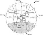
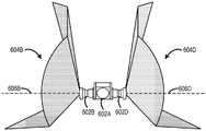
图6和7示意性地示出了示例多相机系统。6 and 7 schematically illustrate example multi-camera systems.
图8是用于控制相机的示例方法的流程图。8 is a flowchart of an example method for controlling a camera.
图9示意地示出示例计算系统。9 schematically illustrates an example computing system.
具体实施方式Detailed ways
在常规相机中,角度分辨率可在相机的图像传感器的不同像素之间变化。如本文所使用的,术语像素的“角度分辨率”是根据从像素的视角来看的、被成像场景中的对象所对向(subtend)的角度来定义的。例如,用于对被成像场景中的人类主体的面部进行成像的像素的数量可以基于场景中人类主体的视野角度和深度而变化。作为一个示例,由于相机中使用的特定类型的透镜的透镜畸变特性,图像传感器的不同像素可具有不同的角度分辨率。在透镜刚性地附连到图像传感器以使得透镜的光轴与图像传感器的光学中心对准的相机中,由透镜类型定义的径向畸变曲线的原点或图像高度对视野角度(IH vs FA)与图像传感器的活动中心或光学中心位于同一位置,使得与透镜光轴对准的水平平面包含跨传感器的位置到跨目标场景的视野角度的映射,该映射遵循从中心到任一水平边缘的IH vs FA关系。对于在图像高度和视野角度之间具有线性关系的透镜类型(即,f-θ透镜类型),具有一致角度分辨率的水平平面与透镜的光轴对准,并且图像传感器的与该平面对准的各像素表示具有在目标场景中对向的基本恒定的角度的相邻投影像素弧,并且因此以相同的角度分辨率进行成像。In conventional cameras, the angular resolution can vary between different pixels of the camera's image sensor. As used herein, the term "angular resolution" of a pixel is defined in terms of the angle subtended by objects in the imaged scene from the pixel's perspective. For example, the number of pixels used to image the face of a human subject in the imaged scene may vary based on the viewing angle and depth of the human subject in the scene. As one example, different pixels of an image sensor may have different angular resolutions due to the lens distortion characteristics of the particular type of lens used in a camera. In cameras where the lens is rigidly attached to the image sensor such that the optical axis of the lens is aligned with the optical center of the image sensor, the origin of the radial distortion curve, or image height versus field of view (IH vs FA), defined by the lens type, is different from the angle of view (IH vs FA). The active center or optical center of the image sensor is co-located such that the horizontal plane aligned with the optical axis of the lens contains a mapping of the position across the sensor to the angle of view across the target scene, which follows the IH vs from the center to either horizontal edge FA relationship. For lens types that have a linear relationship between image height and field of view (ie, f-theta lens types), a horizontal plane with consistent angular resolution is aligned with the optical axis of the lens, and the image sensor's optical axis is aligned with this plane Each pixel of represents an arc of adjacent projected pixels having a substantially constant angle subtending in the target scene, and is therefore imaged with the same angular resolution.
此外,常规相机通常采用低TV畸变(或ftan(θ))透镜,该透镜具有跨与透镜光轴正交的物体一致的空间分辨率的光学平面。此类透镜的直线畸变特性对于许多类型的常见被成像场景(例如,室内房间、平面物体(如页面、标志或海报)、外部景观)以及直线物体在图像中呈直线状(或具有跨与光轴正交的被成像平面物体一致的空间分辨率的直线)的场景是有益的,除其他原因外。然而,对于中高视野相机,低TV畸变透镜的直线畸变特性也会导致图像的角部和边缘的畸变(例如拉伸),因为ftan(θ)透镜图像畸变关系不具有一致角度分辨率的平面。由于成像遵循切线关系,基于投影原点,当从远离代表投影原点的位置的有利地点观看时,效果是明显的,使得视角可能与成像视野不匹配。为了避免此类畸变并实现更高的图像质量,相机可以倾斜(和/或平移)以将感兴趣的主要主体定位在相机视野中受角部/边缘畸变影响最小的区域中。在相机倾斜的场景中,沿水平线超过一定距离的感兴趣的主体会以不一致的角度分辨率被捕获,使得感兴趣的主体发生畸变。此外,在相机被用于对不同距离处的多个感兴趣的主体进行成像的场景中,倾斜相机以对感兴趣的主要主体进行成像会导致以不一致的角度分辨率捕获其他感兴趣的主体(沿水平线定位),这会导致这些其他感兴趣的主体发生畸变。此外,沿图像边缘定位的感兴趣主体可能发生畸变。In addition, conventional cameras typically employ a low TV distortion (or ftan(θ)) lens with an optical plane of consistent spatial resolution across objects orthogonal to the optical axis of the lens. The linear distortion properties of such lenses are linear in the image for many types of commonly imaged scenes (e.g., indoor rooms, flat objects such as pages, signs, or posters, exterior landscapes), and rectilinear objects are imaged plane objects with consistent spatial resolution (straight lines) are beneficial, among other reasons. However, for mid- and high-field cameras, the straight-line distortion characteristics of low-TV distortion lenses can also cause distortion (eg, stretching) in the corners and edges of the image, because the ftan(θ) lens image distortion relationship does not have a plane of uniform angular resolution. Since imaging follows a tangent relationship, based on the projection origin, the effect is pronounced when viewed from a vantage point away from the location representing the projection origin, such that the viewing angle may not match the imaging field of view. To avoid such distortions and achieve higher image quality, the camera can be tilted (and/or panned) to position the main subject of interest in areas of the camera's field of view that are least affected by corner/edge distortion. In scenes where the camera is tilted, subjects of interest beyond a certain distance along the horizon are captured with inconsistent angular resolution, distorting the subject of interest. Furthermore, in scenarios where the camera is used to image multiple subjects of interest at different distances, tilting the camera to image the main subject of interest can result in other subjects of interest being captured at inconsistent angular resolution ( positioning along the horizontal line), which causes distortions in these other subjects of interest. Additionally, objects of interest located along the edges of the image may be distorted.
因此,本公开涉及一种针对径向应用进行优化的相机。具体而言,相机被优化成具有如下水平区域的视野:该水平区域对于距相机的指定径向距离而言具有一致的角度分辨率,以便以最小畸变对一个或多个感兴趣的主体进行成像。此外,相机被配置成使得视野具有垂直角度偏置,该垂直角度偏置将一致角度分辨率的水平区域定位成捕获感兴趣区域,其中感兴趣的主体在被成像场景中最可能位于该感兴趣区域,而不需要相机倾斜来瞄准感兴趣区域。例如,相机可以被配置成将一致角度分辨率的水平区域定位成与感兴趣的主体可能在其中站立或坐着的被成像场景中的感兴趣区域对准。Accordingly, the present disclosure relates to a camera optimized for radial applications. Specifically, the camera is optimized to have a field of view with a horizontal area of consistent angular resolution for a specified radial distance from the camera in order to image one or more subjects of interest with minimal distortion . Additionally, the camera is configured such that the field of view has a vertical angular offset that positions the horizontal area of uniform angular resolution to capture the area of interest where the subject of interest is most likely to be located in the imaged scene area without the need to tilt the camera to aim at the area of interest. For example, the camera may be configured to position a horizontal area of uniform angular resolution in alignment with the area of interest in the imaged scene in which the subject of interest may be standing or sitting.
此类优化可以通过在相机中使用f-θ透镜来实现,以针对水平区域产生跨相机的水平视野一致的角度分辨率。此外,相机的图像传感器可以固定到f-θ透镜,使得f-θ透镜的光轴偏离图像传感器的光学中心,以创建具有相对于f-θ透镜的光轴的垂直角度偏置的视野。经垂直角度偏置的视野对一致角度分辨率的水平区域进行移位以合适地对感兴趣的主体进行成像,而无需倾斜相机。Such optimization can be achieved by using an f-theta lens in the camera to produce angular resolution for horizontal regions that is consistent across the camera's horizontal field of view. Additionally, the camera's image sensor can be fixed to the f-theta lens such that the optical axis of the f-theta lens is offset from the optical center of the image sensor to create a field of view with a vertical angular offset relative to the optical axis of the f-theta lens. The vertically angularly offset field of view shifts a horizontal area of consistent angular resolution to properly image the subject of interest without tilting the camera.
通过以一致的角度分辨率对感兴趣的主体进行成像,可以减少像素浪费,从而优化跨水平区域的像素利用率。此类经优化的像素利用率允许在图像传感器的相似像素跨度内对距相机相似径向距离的相似大小的对象进行成像。对感兴趣主体的这种捕获具有一致的每对象宽度像素比率,其与距相机给定径向距离的视野角无关,这可以允许用于评估图像的人工智能/机器学习模型具有识别在距相机的径向距离内的感兴趣主体的经提高的性能一致性。此外,通过不需要倾斜相机而以低畸变来捕获感兴趣的主体,可以减少可应用于所得图像的畸变校正操作的数量。另外,在相机被用于具有固定位置的设备(例如,包括在已安装的显示器、网络相机或视频会议设备中)的情况下,由于相机的镜筒不必倾斜,因此可以减小设备的形状因子(例如高度)。此外,通过在相机中使用f-θ透镜,像素的分辨率可以跨整个图像传感器上在径向上一致,使得可以用足够高的分辨率对感兴趣的主体进行成像,而不管感兴趣的主体在相机视野中的位置如何。此外,在多相机应用中,当将来自不同相机的多个图像缝合在一起时,诸如用于360度成像时,感兴趣主体的这种低畸变图像可以允许减少处理操作。By imaging the subject of interest with consistent angular resolution, pixel waste can be reduced to optimize pixel utilization across horizontal regions. Such optimized pixel utilization allows imaging of similar sized objects at similar radial distances from the camera within similar pixel spans of the image sensor. This capture of a subject of interest has a consistent pixel-per-object-width ratio that is independent of the angle of view for a given radial distance from the camera, which can allow AI/ML models for evaluating images to have the ability to recognize images at a distance from the camera. Improved performance consistency for a subject of interest within a radial distance of . Furthermore, by capturing the subject of interest with low distortion without needing to tilt the camera, the number of distortion correction operations that can be applied to the resulting image can be reduced. Additionally, where the camera is used in a device with a fixed position (eg, included in a mounted display, web camera, or videoconferencing device), the device's form factor can be reduced because the lens barrel of the camera does not have to be tilted (eg height). Furthermore, by using an f-theta lens in the camera, the resolution of the pixels can be radially uniform across the entire image sensor, so that the subject of interest can be imaged with a sufficiently high resolution, regardless of where the subject of interest is located. How is the position in the camera's field of view. Furthermore, in multi-camera applications, such low-distortion images of a subject of interest may allow for reduced processing operations when stitching together multiple images from different cameras, such as for 360-degree imaging.
图1以简化形式示意性地示出了示例相机100。相机100可以被包括到任何合适的电子设备中,诸如单相机设备、多相机设备(例如,360度多相机系统)、移动电话、头戴式虚拟现实或增强现实设备、平板、膝上型设备、遥控无人机、视频会议设备或另一类型的电子设备。FIG. 1 schematically illustrates an
相机100被配置成对场景102进行成像。相机100包括图像传感器104和f-θ透镜106,f-θ透镜106被定位成将来自场景102的物光107引导到图像传感器104上。在一些实施例中,f-θ透镜106可被包括在两个或更多个透镜或其他光学元件的光学系统中。使得透镜元件保持在透镜镜筒108中,f-θ透镜106可以经由支架安装结构110保持在相对于图像传感器104的固定位置。支架安装结构110可包括任何合适的材料。在一个示例中,支架安装结构110包括金属,诸如铝。在另一示例中,支架安装结构110包括聚合物,诸如玻璃填充聚合物。f-θ透镜106可以按任何合适的方式在操作上耦合到支架安装结构110。在一个示例中,透镜镜筒108和支架安装结构110各自可以是带螺纹的,使得f-θ透镜106被拧入支架安装结构110中。在另一示例中,透镜镜筒108可以是不带螺纹的圆柱形,并通过粘合剂结合到支架安装结构110(诸如放置在带有用于粘合剂的间隙的管状安装架中的杆形镜筒)。Camera 100 is configured to
f-θ透镜106可被用在相机100中,以提供跨图像传感器104的整个水平视野一致的角度分辨率。图3示意性地示出了具有跨相机100的水平视野一致的角度分辨率的示例相机,诸如相机100。由于相机100中的f-θ透镜106的光学特性,图像传感器104的水平面中的每一像素可具有跨在场景102中具有指定径向距离(Z-距离)的弧300的相同角度分辨率。换言之,感兴趣的主体304可位于场景102中沿着弧300的任何位置,并且感兴趣的主体304将使用相机100的图像传感器104的相同数量的像素(P#)来被成像。这种一致的角度分辨率可被应用于场景102中在相机视野的指定水平区域内具有距相机100的任何合适径向距离的任何合适的弧。归因于例如由于感兴趣的主体相对于相机100的位置的姿态角,这种一致的角度分辨率允许以较少的像素对向变化进而以最小的畸变变化来对感兴趣的主体进行成像。The f-theta lens 106 may be used in the
相比之下,使用ftan(θ)透镜的相机以跨相机的视野发生变化的角度分辨率对人类主体进行成像。例如,当人类主体位于沿着场景中的指定弧在相机视野的更高视野角(例如,边缘、角部)时,此类相机可能使用较多数量的像素。此外,当人类主体位于沿着场景中的指定弧在靠近相机视野的中心时,此类相机可能使用较少数量的像素对人类主体进行成像。换言之,具有ftan(θ)透镜的相机不具有跨相机的水平视野一致的角度分辨率,并且因此沿着水平区域,具有f-θ透镜106的相机100可以用比具有ftan(θ)透镜的相机更少的像素对向变化来对人类主体的弧进行成像。In contrast, cameras using ftan(theta) lenses image human subjects with angular resolution that varies across the camera's field of view. For example, such cameras may use a higher number of pixels when human subjects are located at higher viewing angles (eg, edges, corners) of the camera's field of view along specified arcs in the scene. Furthermore, such cameras may use a smaller number of pixels to image the human subject when the human subject is located close to the center of the camera's field of view along a designated arc in the scene. In other words, a camera with an ftan(theta) lens does not have a consistent angular resolution across the camera's horizontal field of view, and thus along the horizontal area, a
返回图1,在所示的非限制性示例相机100中,透镜镜筒108在操作上耦合到支架安装结构110。支架安装结构110被安装到印刷电路板(PCB)112。在一个示例中,支架安装结构110经由粘合剂结合到PCB 112。图像传感器104安装在PCB 112上,使得f-θ透镜106的光轴114具有相对于图像传感器104的光学中心118的固定偏移。具体而言,光轴114从图像传感器104的光学中心118垂直地移位。Returning to FIG. 1 , in the
透镜镜筒108、支架安装结构110以及PCB 112共同保持f-θ透镜106与图像传感器104光学对准(例如,对于使用螺纹透镜镜筒108和支架安装结构110的情形,支架安装结构110可以相对于PCB 112接合就位,以固定x、y、z位置和尖端/倾斜角,同时螺纹可以基本上用于设置焦点)。或者,与使用主动对准(AA)的情形一样,预聚焦位置可以通过光学或机械方式在透镜镜筒108和支架安装结构110之间固定聚焦位置来设置。一旦以这种方式固定,透镜和支架组装件就可以在所有自由度上进行主动调整,并通过支架安装结构110和PCB112之间的间隙接合来进行接合,以固定x、y、最终z焦点、尖端、倾斜和方位旋转。The
在一些示例中,支架安装结构110是刚性支架结构,其沿着六个自由度(例如,x、y、z、尖端、倾斜、方位旋转)的每个轴固定透镜镜筒108,并且从而相对于图像传感器104来固定f-θ透镜106中的所有元件。例如,固定焦点相机可具有此类布置。在一些示例中,支架安装结构110可允许透镜镜筒108相对于图像传感器104沿至少一个轴移动(例如,用于图像稳定化和/或聚焦,诸如通过在透镜镜筒108和支架安装结构110之间放置自动聚焦音圈致动器)。在此类示例中,即使f-θ透镜106的位置可以相对于图像传感器104的位置沿Z轴移动,f-θ透镜106的光轴114和图像传感器104的光学中心118之间的偏移仍然是固定的。In some examples, the
如上所述,f-θ透镜106的光轴114具有相对于图像传感器104的光学中心118的固定偏移。在所示的示例中,图像传感器104被示为具有相对于与f-θ透镜106在光学上对准的假想图像传感器104’的位置移位的位置。如侧边栏122所示,f-θ透镜106的光轴将与假想图像传感器104’的光学中心120对准。然而,实际图像传感器104相对于f-θ透镜106向下垂直移位(即,沿着Y轴),使得图像传感器104的实际光学中心118与f-θ透镜106的光轴114垂直地偏移开。假想图像传感器104’的光学中心120(以及相应地f-θ透镜106的光轴114)和图像传感器104的实际光学中心118之间的偏移使图像传感器104所捕获的视野相对于假想图像传感器的视野发生垂直角度偏置。换言之,图像传感器104’的视野相对于光学中心120垂直地对称,而图像传感器104的视野相对于光学中心118垂直地偏置。透镜在图像传感器成像平面上形成真实的反转图像,位于由透镜f-θ设计所确定的图像圈内。由于透镜的成像属性,沿成像平面的垂直维度的像素位置映射到沿目标场景中垂直轴的视野角的角指向(angular pointing)。对于透镜光轴指向水平面的相机,假想图像传感器104’从透镜图像圈的中心部分捕获图像,从而包含垂直视野的从水平面向上和向下的相等部分。被成像内容绕光轴对称,并且因此图像中心表示的指向角与透镜光轴之间没有角度偏移。然而,由于图像传感器104向下移位,因此透镜在图像传感器成像平面处形成真实的反转图像,使得图像传感器捕获透镜的图像圈的垂直地偏移的下部,因此感测区的下边缘对于目标场景中的高视野角进行成像,而感测区的上边缘对于目标场景中的低视野角进行成像。该偏移配置提供由图像的中心表示的指向角与透镜的光轴之间的角度偏移,在这一情形中是向上偏移角,如图1所示。请注意,x,y反转图像由图像传感器读出次序进行计算和校正,以便图像看起来与目标场景的观看者所看到的一样。这种垂直角度偏置优化了相机的视野,以沿着视野的水平区域一致的角度分辨率来捕获感兴趣的主体,如将在下文进一步详细讨论的。As described above, the
注意在所示示例中,f-θ透镜106被配置成接受来自场景102的一区域(例如,图像圈)的物光,并且其中图像传感器104的大小被调整为对小于场景102的该区域的子区域进行成像。换言之,f-θ透镜106的接受区大于图像传感器104的感测区(例如,像素区)。该大小关系允许图像传感器104相对于f-θ镜106移位,而不限制图像传感器的视野。在其他实现中,图像传感器104的大小可以使其对大于f-θ透镜106的接受区的区域(即,f-θ透镜106的接受区小于图像传感器104的感测区(例如,像素区))进行成像。Note that in the example shown, the f-theta lens 106 is configured to accept object light from an area of the scene 102 (eg, the image circle), and wherein the
此外,注意,在所示的示例中,图像传感器104的光学中心118与f-θ透镜的光轴114水平地对准。在其他示例中,作为垂直地偏移的替换或补充,图像传感器的光学中心可以与f-θ透镜的光轴水平地偏移开,以便水平地移位图像传感器104的视野的偏置。Also, note that in the example shown, the
图像传感器104的光学中心118可以相对于f-θ透镜106的光轴114垂直地偏移任意合适的距离,以垂直地对图像传感器104的视野进行角度偏置。在一些示例中,偏移距离至少是图像传感器104的高度的15%。在更具体的示例中,偏移距离是图像传感器104的高度的约20%到25%。例如,如果图像传感器的高度是约4毫米,则偏移距离可以是约1毫米。本文可设想其他偏移距离。The
如上所述,图像传感器104和f-θ透镜106之间的偏移垂直地偏置图像传感器104的视野,以垂直地移位一致角度分辨率的水平区域的位置。具体而言,一致角度分辨率的水平区域被定位成捕获场景102中的感兴趣区域,其中感兴趣的主体最有可能位于该感兴趣区域中,而无需将相机100倾斜以对准感兴趣区域。图4示出了由诸如相机100之类的相机进行成像的示例场景的示例视野角绘图(map)400。视野角绘图400的透视图是相机100和场景的侧视图。从相机100径向延伸的实线表示视野角。例如,80度视野角在相机100上方延伸,而负80度视野角在相机下方延伸。虚弧线表示距相机的不同径向距离。与每一弧线相关联的数字表示用于对人类主体的脸部进行成像的示例指定角度像素密度或像素/度比率(例如,跨脸部54个像素)。注意,在其他示例中可使用其他角度像素密度要求。在另一示例中,用于对人脸进行成像的指定角度像素密度要求是跨脸部35个像素。角度像素密度要求可以是因应用而异的。例如,角度像素密度要求可以基于使用用于脸部识别、脸部检测或其他形式的机器视觉的捕获。沿视野绘图400的x轴列出了距离,而沿y轴列出了高度。As described above, the offset between the
相机100具有水平区域(H-区域)402的视野,该水平区域402对于距相机100的指定径向距离(每一虚弧线)具有一致的角度分辨率,以便以最小畸变对一个或多个感兴趣的主体进行成像。水平区域402在视野中的大小和位置被调整成捕获处于各种位置的各种大小的人类主体。例如,水平区域402可以捕捉较矮坐姿高度、平均坐姿高度、较高坐姿高度、较矮站姿高度、平均站姿高度和较高站姿高度的人类主体。水平区域402被定位成允许对位于(坐着或站着)距相机100相对远的距离(例如,~11英尺)处的感兴趣主体以合适的像素分辨率进行成像(例如,每度角像素密度22个像素以跨人类主体的脸部对54个像素进行成像)。如果人类主体在水平区域402内移动得更靠近相机100,则人类主体的脸部的像素分辨率将简单地增加。以此方式,相机100被配置成具有良好的深度性能,或者在近距离到远距离范围内具有可接受的性能,用于以机器视觉的可接受像素分辨率来捕获人类主体,并且可以考虑用于观看者可消费的图像内容。The
水平区域402可以具有任何合适的大小以使用一致角度分辨率和最小畸变来捕获对象。在一些示例中,水平区域402可以覆盖距图像传感器的光学中心至少+/-20度的仰角。在一些示例中,视野的水平区域402可包括视野的垂直尺寸的至少40%。本文可以设想其他合适的水平区域尺寸。
视野具有垂直角度偏置,该垂直角度偏置将一致角度分辨率的水平区域定位成捕获感兴趣区域,其中感兴趣的主体在被成像场景中最可能位于该感兴趣区域,而不需要相机倾斜来瞄准感兴趣区域。例如,图像传感器和f-θ透镜被定向成使得光轴基本上平行于水平线。除其他工业设计优点外,相对于具有倾斜相机配置的设备而言,相机100在设备内的这种平面/水平物理定位可以降低该设备的高度形状因子。The field of view has a vertical angular offset that positions a horizontal area of consistent angular resolution to capture the area of interest where the subject of interest is most likely to be located in the scene being imaged, without the need for camera tilt to target the area of interest. For example, the image sensor and f-theta lens are oriented such that the optical axis is substantially parallel to the horizontal. Among other industrial design advantages, this planar/horizontal physical positioning of the
返回图1,相机100还包括控制器116,控制器116被配置成控制图像传感器104以采集场景102的图像,以及执行本文所讨论的相机100的其他控制操作。控制器116可包括逻辑子系统和存储子系统。逻辑子系统包括配置成执行存储子系统所保持的指令以执行本文公开的任何操作、算法、计算或转换的一个或多个物理设备。在一些实现中,逻辑子系统可以采取专用集成电路(ASIC)或片上系统(SoC)的形式,其中指令中的一些或全部是硬件编码或固件编码的。控制器116的逻辑子系统和存储子系统参考图9进一步详细讨论。Returning to FIG. 1, the
如本文所使用的,术语“原始图像”是指在没有任何畸变校正的情况下生成的图像,并且可以包括单色图像、彩色图像和至少部分地经处理的图像(例如,应用拜耳Bayer滤波器)。相机100可被配置成校正图像畸变以用于图像呈现、将物理场景的多个图像缝合在一起以形成全景图像、以及用于输入到机器学习模型,以及其他应用。如图2所示,控制器116被配置成经由图像传感器104采集场景的原始图像204。控制器116可以被配置成将原始图像204加载到相机100的存储器202中。控制器116可以包括畸变校正机206,其被配置成根据畸变校正投影212平移原始图像204的诸像素的像素位置,以生成经畸变校正的图像214。As used herein, the term "raw image" refers to an image that is generated without any distortion correction, and can include monochrome images, color images, and at least partially processed images (eg, applying a Bayer filter ).
畸变校正投影212可以将原始图像204的像素位置和经畸变校正的图像214的经平移像素位置之间的关系定义为逆函数,其中传感器坐标被映射到畸变校正投影212的投影平面和/或表面坐标。畸变校正投影212可采取任何合适的形式。例如,畸变校正投影212可以包括圆柱形投影、球形投影或两个或更多个不同畸变校正投影的组合。此外,可以使用透镜指向和投影的其他取向。例如,场景的360°水平扫描成像可以与球形投影和圆柱形投影中的任一者或组合一起使用。The distortion-corrected
在一些实现中,畸变校正机206可以被配置成从多个不同的畸变校正投影(例如,直线、球形和圆柱形)中选择畸变校正投影212,以便根据所选择的畸变校正投影来生成经畸变校正的图像214。畸变校正机206可以按任何合适的方式从多个不同的畸变校正投影中选择畸变校正投影。在一些示例中,畸变校正机206可以基于相机100的工作条件从多个不同的畸变校正投影中动态地选择畸变校正投影。在一些示例中,畸变校正机206可被配置成至少基于相机100的操作模式从多个不同的畸变校正投影中选择畸变校正投影。In some implementations, the
在一些示例中,畸变校正机206可被配置成至少基于指示对畸变校正投影的选择的用户输入来从多个不同的畸变校正投影中选择畸变校正投影。例如,相机100可任选地包括显示器,并且多个不同的畸变校正投影中的每一者可以在显示器上呈现的用户界面中被列出和/或预览。相机100的用户可以选择畸变校正投影之一,以被用于生成畸变校正图像214。可以基于任何合适类型的用户输入从多个不同的畸变校正投影中选择畸变校正投影。In some examples, the
畸变校正机206可被配置成根据畸变投影212以任何合适的方式确定原始图像的诸像素的像素位置和经畸变校正的图像214的诸像素的经平移的像素位置之间的关系。畸变校正机206可以被配置成根据使用图像传感器参数208和/或透镜畸变参数210作为输入的畸变校正投影212来执行畸变校正映射。在一个示例中,图像传感器参数208可包括图像传感器104的分辨率(例如,在x和y维度两者中包括在图像传感器中的像素数量)和图像传感器104的诸像素的像素大小(例如,在x和y维度两者中的像素的大小)。在其他示例中,对于畸变校正投影212,可以考虑其他图像传感器参数。
在一些示例中,畸变校正机206可被配置成使用查找表,该查找表基于图像传感器参数208和透镜畸变参数210根据畸变校正投影212将原始图像的诸像素的像素位置映射到经畸变校正的图像的诸像素的经平移的像素位置。在一些示例中,畸变校正机206可被配置成使用拟合方程,其中拟合方程的参数是从图像传感器参数208和透镜畸变参数210导出的。在一些示例中,畸变校正机206可被配置成使用抛物线百分比(p)畸变作为原始图像204的视野角的函数来估计经平移的像素位置。In some examples,
在其他示例中,畸变校正机206可任选地被配置成进一步至少基于图像传感器旋转参数来生成经畸变校正的图像214。在经畸变校正的图像214被包括在缝合在一起的多个图像(例如全景图像或3D图像)中的情形中,可以考虑图像传感器旋转参数用于像素映射。对于使用f-θ透镜106和图像传感器104的特定类型的相机配置,传感器参数208和透镜畸变参数210可以是先验已知的。在一些实现中,传感器参数208和透镜畸变参数210可以存储在存储器202中,并且在一些实现中,传感器参数208和透镜畸变参数可以硬编码到畸变校正机206的畸变校正算法中。In other examples, the
注意,如在基于畸变校正投影的个体像素的基础上,通过指示经畸变校正的图像的每一整数(x,y)像素到原始输入图像(x',y')内的浮点位置的映射的网状网格,原始图像中不同像素的像素位置可以被平移和/或内插。如此,在不同的实例中,不同像素的像素位置可以被不同地平移(例如,不同像素的不同平移方向和/或距离),不同像素的像素位置可以被相同地平移(例如,不同像素的相同平移方向和/或距离),和/或一些像素的像素位置可以在原始图像204和经畸变校正的图像214之间保持相同。此外,畸变校正可包括拉伸和/或压缩图像的各部分。Note that by indicating the mapping of each integer (x,y) pixel of the distortion-corrected image to a floating point position within the original input image (x',y'), as on the basis of the individual pixels of the distortion-corrected projection A mesh grid where the pixel positions of different pixels in the original image can be translated and/or interpolated. As such, in different instances, pixel positions for different pixels may be translated differently (eg, different translation directions and/or distances for different pixels), and pixel positions for different pixels may be translated identically (eg, the same for different pixels translation direction and/or distance), and/or the pixel positions of some pixels may remain the same between the original image 204 and the distortion-corrected image 214. Additionally, distortion correction may include stretching and/or compressing portions of the image.
在一些实现中,控制器116可以被配置成,诸如在多相机系统中(例如,图6和图7所示的多相机系统600)控制多个相机。在此类实现中,畸变校正机206可以被配置成从不同相机接收多个原始图像204。不同原始图像可以由不同相机同时捕获,并且可以具有场景102的不同视野。例如,不同相机可以相对彼此固定,使得不同视野共同捕获场景102的360度视图。畸变校正机206可以被配置成执行该多个图像的图像处理操作,以将该多个图像缝合在一起来形成场景的全景图像216。在一些示例中,全景图像可以是场景102的360度图像。畸变校正机206可被配置成执行任何合适的图像处理操作,以将多个图像缝合在一起以形成全景图像。在一些示例中,畸变校正机206可以被配置成执行多个阶段的处理操作。例如,畸变校正机206可以首先对每一图像执行畸变校正操作,并随后将经畸变校正的图像缝合在一起,以生成经畸变校正的经缝合的全景图像216。控制器116包括一个或多个机器学习对象检测模型218,其被配置成分析经由图像传感器采集的经畸变校正的图像214/216以检测和/或识别经畸变校正的图像214/216中的内容。机器学习对象检测模型218可以采用任何合适的机器视觉技术来检测和/或识别图像中的内容。作为非限制性示例,机器学习对象检测模型可包括一个或多个先前训练的人工神经网络。在一些示例中,机器学习对象检测模型218可以被配置成执行较低级别的分析以标识图像内的特征,例如可以指示选择哪一畸变校正投影的角部和边缘。在其他示例中,机器学习对象检测模型218可被配置成执行更高级别的分析以识别图像中的对象,诸如不同的人。在一些示例中,机器学习对象检测模型218可预先训练以执行面部识别来标识图像中的感兴趣的主体。机器学习对象检测模型218可以预先训练来输出至少一个置信度分数,该置信度分数指示在经畸变校正的图像214/216中存在对应对象的置信度。例如,机器学习对象检测模型218可以被训练来输出与人类主体相对应的置信度(例如,图像中存在人类主体的置信度是93%)。在一些实现中,机器学习对象检测模型218先前已被训练来输出与图像中可能存在的不同感兴趣的主体相对应的多个置信度分数(例如,Steve在图像中的置信度是93%,Phil在图像中的置信度是3%)。在一些实现中,机器学习对象检测模型218可被配置成在同一图像中标识两个或更多个不同的感兴趣主体,并输出每一这样的感兴趣主体的一个或多个置信度分数(Steve在图像的第一部分中的置信度是93%;Phil在图像的第二部分中的置信度是88%)。In some implementations, controller 116 may be configured to control multiple cameras, such as in a multi-camera system (eg,
控制器116可以被配置成以任何合适的形式输出经畸变校正的图像214/216。在一些示例中,控制器116可将经畸变校正的图像214/216输出为定义像素矩阵的数据结构,每一像素包括值(例如,颜色/亮度/深度)。控制器116可以被配置成将经畸变校正的图像214/216输出到相机100内部或外部的任何合适的接收者。在一个示例中,控制器116可被配置成将经畸变校正的图像214/216输出到另一处理组件以进行附加图像处理(例如,滤波、计算机视觉、图像压缩)。在一些示例中,处理组件可被结合到相机100中。在一些示例中,处理组件可被结合到与相机100通信的远程计算设备中。在另一示例中,控制器116可被配置成将经畸变校正的图像214/216输出到内部或外部显示设备以进行视觉呈现。Controller 116 may be configured to output distortion corrected images 214/216 in any suitable form. In some examples, the controller 116 may output the distortion corrected images 214/216 as a data structure defining a matrix of pixels, each pixel including a value (eg, color/brightness/depth). Controller 116 may be configured to output distortion corrected images 214 / 216 to any suitable recipient, internal or external to
图5示出了示例原始图像500和示例经畸变校正的图像502。原始图像500包括同心圆形式的诸轮廓线,其表示f-θ透镜的视野角(以度为单位)。作为一个示例,f-θ透镜可以在图像平面上的图像圈内支撑高达180度。在所示示例中,诸轮廓线表示从0度到90度的10度增量。原始图像500中的外围线(outline)504表示基于图像传感器相对于f-θ透镜的大小和位置的经畸变校正的图像502的帧边缘。在所示示例中,原始图像500由支持约131度水平视野的相机生成,且图像传感器相对于f-θ透镜的光轴垂直地偏移约0.95毫米。一致角度畸变的水平区域506位于距f-θ透镜的光轴的水平面约+/-20度的仰角范围内。FIG. 5 shows an example
原始图像500是利用极投影(诸如球形或圆柱形投影)来进行畸变校正的,以产生经畸变投影校正的图像502。两个畸变校正投影之间的主要区别在于,由于垂直轴的切线关系,与球形经畸变校正的图像相比,圆柱形经畸变校正的图像的高度将被拉伸。可以对原始图像500进行畸变校正,以适合经畸变投影校正的图像502的矩形帧边缘,使得将畸变投影校正的图像502适于呈现,诸如在显示器上。此外,在一些使用场景中,诸如对于机器视觉,由于原始图像500中的外围线504之外的图像内容可以包括在畸变校正输出中,因此经校正的图像可能不需要局限于经畸变校正的图像502的矩形框边。
在一些实现中,导出的投影映射方程可以作为矩阵运算来执行,以便于并行地计算经畸变校正的图像内的所有像素。作为一个示例,可为x值的二维(2D)数组X和y值的2D数组Y这两者生成网状网格数组。2D数组X可以从一维(1D)x位置网格被导出,2D数组Y可以从经畸变校正的图像802的1D y位置网格被导出。给定投影方程的矩阵计算可应用于2D数组X和Y,以确定原始图像500中X'值的2D阵列X'和原始图像500中y'值的2D阵列Y'。2D阵列X'和Y'中的值表示原始图像500中投影到经畸变校正的图像502中的(x,y)像素位置(例如,整数(x,y)像素值)的(x’,y’)像素位置。在一些示例中,该操作可以包括插值,以便提高经畸变校正的图像502到原始图像500的映射的分辨率。在此类示例中,分数像素位置(例如,浮点(x’,y’)像素值)可以通过该操作生成。此外,在一些示例中,矩阵数组X'和Y'可被用于在设备内的固件中执行给定的投影映射。在一些此类示例中,可以按适合于视频的帧速率来执行这样的畸变校正投影映射。In some implementations, the derived projection mapping equations may be performed as matrix operations to facilitate computing all pixels within the distortion-corrected image in parallel. As one example, a mesh grid array may be generated for both a two-dimensional (2D) array X of x values and a 2D array Y of y values. The 2D array X can be derived from a one-dimensional (1D) x position grid, and the 2D array Y can be derived from a 1D y position grid of the distortion corrected
图6和7示意性地示出了示例多相机系统600。图6示意性地示出了多相机系统600的俯视图。图7示意性地示出了多相机系统600的侧视图。多相机系统600包括多个相机602(例如,602A、602B、602C、602D)。多个相机602可以代表图1所示的相机100。在一些实现中,多相机系统600中的多个相机602可以由共享控制器控制,诸如图2所示的控制器116。6 and 7 schematically illustrate an
多个相机602中的每一者都具有相对于多相机系统600的每一其他相机的固定位置。具体而言,多个相机的诸f-θ透镜的光轴基本上是共面的。换言之,没有相机被倾斜,倾斜可能会降低多相机系统600的高度形状因子。Each of the plurality of cameras 602 has a fixed position relative to every other camera of the
在所示示例中,多相机系统600包括四个相机,并且每一相机与每一相邻相机在径向上偏移90度,使得每一相机602具有指向不同基本方向的视野604(例如604A、604B、604C、604D)。每一相机的视野与每一相邻相机的视野交叠。例如,相机602A的视野604A与相机604B的视野604B和相机604D的视野604D交叠。如图7所示,基于每一相机602中的图像传感器和f-θ透镜的偏移配置,每一视野604垂直地偏置。换言之,每一视野604相对于相机602的f-θ透镜的光轴606不是垂直对称的。相对于其中对于每一相机,图像传感器的光学中心与透镜的光轴对准并且相机向上倾斜以捕获场景的配置而言,视野的这一垂直偏置在诸相邻相机的视野之间提供了更大的交叠。此类增加的交叠提供了如下益处:需要经减少数目的处理操作就能将多个相机602所捕获的图像缝合在一起以生成经缝合的全景图像(例如,360度图像)。In the example shown, the
多相机系统可包括以相对于彼此的任何合适方式来布置的任何合适数量的相机,以便共同提供针对场景的指定区域的视野。例如,对于使用不同于四个相机(例如,2、3、5、6或更多)的多相机系统实现而言,诸相机可以相对于彼此布置成使得一个相机的视野与多相机系统的至少一个其他相机的视野交叠,以便共同提供针对场景的指定区域的视野。图8是用于控制相机的示例方法800的流程图。例如,方法800可以由图1所示的相机100的控制器116来执行。在一些实现中,控制器116可以被配置成控制包括多个相机的多相机系统,诸如图6和图7中所示的多相机系统600。在802,通过一个或多个相机的图像传感器来采集场景的一个或多个原始图像。在804,从一个或多个畸变校正投影中选择畸变校正投影。在一些实现中,畸变校正投影可以从多个不同的畸变校正投影(例如,球形、圆柱形、360度球形、360度圆柱形)中进行选择。在806,通过根据所选择的畸变校正投影平移原始图像的诸像素的像素位置来输出一个或多个经畸变校正的图像。在从多相机系统的多个相机采集多个原始图像的一些实现中,在808,可任选地,可通过将对应于多个不同相机的多个经畸变校正的图像缝合在一起来输出场景的经缝合的全景图像。在一些示例中,经缝合的全景图像可以是场景的360度图像。在一些实现中,在810,可任选地,可通过一个或多个机器学习对象检测模型来评估经畸变校正的图像。每一机器学习对象检测模型可以预先训练来输出至少一个置信度分数,该置信度分数指示在经畸变校正的图像中存在对应对象的置信度。在一些示例中,机器学习对象检测模型可预先训练以执行场景中的一个或多个人类主体的面部识别。A multi-camera system may include any suitable number of cameras arranged in any suitable manner relative to each other to collectively provide a field of view for a designated area of a scene. For example, for multi-camera system implementations using different than four cameras (eg, 2, 3, 5, 6, or more), the cameras may be arranged relative to each other such that the field of view of one camera is at least the same as that of the multi-camera system. The fields of view of one of the other cameras overlap to collectively provide a field of view for a specified area of the scene. 8 is a flowchart of an
本文所描述的方法和过程可以与一个或多个计算设备的计算系统绑定。具体而言,此类方法和过程可被实现为可执行计算机应用程序、网络可访问的计算服务、应用编程接口(API)、库或上述和/或其他计算资源的组合。The methods and processes described herein may be tied to the computing system of one or more computing devices. In particular, such methods and processes may be implemented as executable computer applications, network-accessible computing services, application programming interfaces (APIs), libraries, or combinations of the foregoing and/or other computing resources.
图9示意性地示出了计算系统900的简化表示,该计算系统900被配置成提供本文中描述的任何乃至所有计算功能性。计算系统900可采取下列各项的形式:一个或多个相机、个人计算机、网络可访问的服务器计算机、平板计算机、家庭娱乐计算机、游戏设备、移动计算设备、移动通信设备(例如,智能电话)、虚拟/增强/混合现实计算设备、可穿戴计算设备、物联网(IoT)设备、嵌入式计算设备、和/或其他计算设备。例如,计算系统900可以采取图1所示的相机100的形式,或者图6和7所示的多相机系统600的任一相机602的形式。FIG. 9 schematically shows a simplified representation of a
计算系统900包括逻辑子系统902和存储子系统904。计算系统900可任选地包括显示子系统906、输入子系统908、通信子系统910、和/或在图9中未示出的其他子系统。
逻辑子系统902包括被配置成执行指令的一个或多个物理设备。例如,逻辑子系统902可被配置成执行作为一个或多个应用、服务、或其他逻辑构造的一部分的指令。逻辑子系统902可包括被配置成执行软件指令的一个或多个硬件处理器。附加地或替换地,逻辑子系统902可包括被配置成执行硬件或固件指令的一个或多个硬件或固件设备。逻辑子系统902的处理器可以是单核的或多核的,并且其上所执行的指令可被配置成用于串行、并行和/或分布式处理。逻辑子系统902的各个个体组件可任选地分布在两个或更多个分开的设备中间,这些设备可位于远程并且/或者被配置成用于协同处理。逻辑子系统902的各方面可由以云计算配置进行配置的可远程访问的联网计算设备来虚拟化和执行。Logic subsystem 902 includes one or more physical devices configured to execute instructions. For example, logic subsystem 902 may be configured to execute instructions that are part of one or more applications, services, or other logical constructs. Logic subsystem 902 may include one or more hardware processors configured to execute software instructions. Additionally or alternatively, logic subsystem 902 may include one or more hardware or firmware devices configured to execute hardware or firmware instructions. The processors of logic subsystem 902 may be single-core or multi-core, and the instructions executed thereon may be configured for serial, parallel, and/or distributed processing. The various individual components of logic subsystem 902 may optionally be distributed among two or more separate devices, which may be located remotely and/or configured for cooperative processing. Aspects of logic subsystem 902 may be virtualized and executed by remotely accessible networked computing devices configured in a cloud computing configuration.
存储子系统904包括被配置成临时和/或永久地保持计算机信息(诸如可由逻辑子系统902执行的数据和指令)的一个或多个物理设备。当存储子系统904包括两个或更多个设备时,这些设备可以共处一处和/或位于远程。存储子系统904可包括易失性、非易失性、动态、静态、读/写、只读、随机存取、顺序存取、位置可寻址、文件可寻址和/或内容可寻址设备。存储子系统904可以包括可移动和/或内置设备。当逻辑子系统902执行指令时,存储子系统904的状态可被变换——例如,以保持不同的数据。
逻辑子系统902和存储子系统904的各方面可以被一起集成到一个或多个硬件逻辑组件中。此类硬件逻辑组件可包括例如程序和应用专用集成电路(PASIC/ASIC)、程序和应用专用标准产品(PSSP/ASSP)、片上系统(SOC)、以及复杂可编程逻辑器件(CPLD)。例如,逻辑子系统和存储子系统可被包括在图1和2所示的控制器116中。Aspects of logic subsystem 902 and
逻辑子系统902和存储子系统904可以协作以实例化一个或多个逻辑机。图2中所示的畸变校正机206和机器学习对象检测模型218是此类逻辑机的示例。如本文所使用的,术语“机器”被用来统一指代硬件、固件、软件、指令、和/或协作以提供计算机功能性的任何其他组件的组合。换言之,“机器”从来都不是抽象概念,而总是具有有形形式。机器可以由单个计算设备实例化,或者机器可以包括由两个或更多个不同计算设备实例化的两个或更多个子组件。在一些实现中,机器包括与远程组件(例如,由服务器计算机的网络提供的云计算服务)协作的本地组件(例如,由计算机处理器执行的软件应用)。赋予特定机器其功能性的软件和/或其他指令可任选地被保存为一个或多个合适的存储设备上的一个或多个未执行模块。Logic subsystem 902 and
机器可使用现有技术和/或未来机器学习(ML)、人工智能(AI)和/或自然语言处理(NLP)技术的任何合适的组合来实现。可包括在一个或多个机器的实现中的技术的非限制性示例包括:支持向量机、多层神经网络、卷积神经网络(例如,包括用于处理图像和/或视频的空间卷积网络、用于处理音频信号和/或自然语言句子的时间卷积神经网络,和/或配置成卷积和池化跨一个或多个时间和/或空间维度的特征的任何其他合适的卷积神经网络)、递归神经网络(例如,长-短期记忆网络)、联想存储器(例如,查找表、哈希表、Bloom滤波器、神经图灵机和/或神经随机存取存储器)、字嵌入模型(例如,GloVe或Word2Vec)、无监督空间和/或聚类方法(例如,最近邻算法、拓扑数据分析和/或k-均值聚类)、图形模型(例如(隐藏)马尔可夫模型、马尔可夫随机场、(隐藏)条件随机场和/或AI知识库)和/或自然语言处理技术(例如,标记化、词干提取、构成和/或依赖分析、和/或意图识别、分段模型和/或超分段模型(例如,隐藏动态模型))。Machines may be implemented using any suitable combination of existing and/or future machine learning (ML), artificial intelligence (AI) and/or natural language processing (NLP) techniques. Non-limiting examples of techniques that may be included in an implementation of one or more machines include: support vector machines, multilayer neural networks, convolutional neural networks (eg, including spatial convolutional networks for processing images and/or video) , a temporal convolutional neural network for processing audio signals and/or natural language sentences, and/or any other suitable convolutional neural network configured to convolve and pool features across one or more temporal and/or spatial dimensions networks), recurrent neural networks (e.g., long-short term memory networks), associative memories (e.g., look-up tables, hash tables, Bloom filters, neural Turing machines, and/or neural random access memory), word embedding models (e.g., , GloVe or Word2Vec), unsupervised spatial and/or clustering methods (e.g. nearest neighbor algorithm, topological data analysis and/or k-means clustering), graphical models (e.g. (hidden) Markov models, Markov random fields, (hidden) conditional random fields and/or AI knowledge bases) and/or natural language processing techniques (e.g. tokenization, stemming, composition and/or dependency analysis, and/or intent recognition, segmentation models and /or a hyper-segmented model (e.g., a hidden dynamic model)).
在一些示例中,可使用一个或多个可微函数来实现本文描述的方法和过程,其中可微函数的梯度可参考可微函数的输入和/或输出(例如,参考训练数据和/或参考目标功能)来计算和/或估计。此类方法和过程可至少部分地由一组可训练的参数来确定。因此,用于特定方法或过程的可训练参数可通过任何适当的训练规程来调整,以便持续地改进该方法或过程的功能。In some examples, the methods and processes described herein may be implemented using one or more differentiable functions, wherein the gradient of the differentiable function may refer to the input and/or output of the differentiable function (eg, with reference to training data and/or reference target function) to calculate and/or estimate. Such methods and processes may be determined, at least in part, by a set of trainable parameters. Thus, the trainable parameters for a particular method or process can be adjusted by any suitable training protocol in order to continuously improve the function of the method or process.
用于调整可训练参数的训练规程的非限制性示例包括有监督训练(例如,使用梯度下降或任何其他合适的优化方法)、零样本(zero-shot)、少样本(few-shot)、无监督学习方法(例如,基于从无监督聚类方法导出的类的分类)、强化学习(例如基于反馈的深度Q学习)和/或生成性对抗神经网络训练方法、信念传播、RANSAC(随机样本共识)、带上下文的bandit方法、最大似然方法和/或期望最大化。在一些示例中,可参考测量多个组件的集体功能的性能的目标功能(例如,参考增强反馈和/或参考经标记的训练数据)同时训练本文描述的系统的多个方法、过程和/或组件。同时训练多种方法、过程和/或组件可改进此类集体功能。在一些示例中,一个或多个方法、过程和/或组件可独立于其他组件来训练(例如,对历史数据进行离线训练)。Non-limiting examples of training procedures for tuning trainable parameters include supervised training (eg, using gradient descent or any other suitable optimization method), zero-shot, few-shot, no Supervised learning methods (eg, classification based on classes derived from unsupervised clustering methods), reinforcement learning (eg, feedback-based deep Q-learning) and/or generative adversarial neural network training methods, belief propagation, RANSAC (random sample consensus) ), bandit methods with context, maximum likelihood methods, and/or expectation maximization. In some examples, various methods, processes, and/or methods of the systems described herein may be simultaneously trained with reference to a target function that measures the performance of the collective functions of multiple components (eg, with reference to augmented feedback and/or with reference to labeled training data). components. Training multiple methods, procedures, and/or components simultaneously can improve such collective functions. In some examples, one or more methods, processes, and/or components may be trained independently of other components (eg, offline training on historical data).
当被包括时,显示子系统906可被用来呈现由存储子系统904保持的数据的视觉表示。该视觉表示可采取图形用户界面(GUI)的形式。显示子系统906可包括利用实质上任何类型的技术的一个或多个显示设备。在一些实现中,显示子系统906可包括一个或多个虚拟现实、增强现实或混合现实显示器。When included,
在包括输入子系统908时,输入子系统908可以包括或对接于一个或多个输入设备。输入设备可包括传感器设备或用户输入设备。用户输入设备的各示例包括键盘、鼠标、触摸屏或游戏控制器。在一些实现中,输入子系统908可以包括所选择的自然用户输入(NUI)部件或与其对接。此类部件可以是集成的或外围的,并且输入动作的换能和/或处理可以在板上或板外被处置。示例NUI部件可以包括用于语音和/或话音识别的话筒;用于机器视觉和/或姿势识别的红外、彩色、立体和/或深度相机;以及用于运动检测和/或意图识别的头部跟踪器、眼部跟踪器、加速度计、和/或陀螺仪。Where input subsystem 908 is included, input subsystem 908 may include or interface with one or more input devices. Input devices may include sensor devices or user input devices. Examples of user input devices include a keyboard, mouse, touch screen, or game controller. In some implementations, the input subsystem 908 may include or interface with selected natural user input (NUI) components. Such components may be integrated or peripheral, and the transduction and/or processing of input actions may be handled on-board or off-board. Example NUI components may include microphones for speech and/or voice recognition; infrared, color, stereo and/or depth cameras for machine vision and/or gesture recognition; and heads for motion detection and/or intent recognition Trackers, eye trackers, accelerometers, and/or gyroscopes.
当包括通信子系统910时,通信子系统910可被配置成将计算系统900与一个或多个其他计算设备通信地耦合。通信子系统910可包括与一个或多个不同通信协议兼容的有线和/或无线通信设备。通信子系统910可以被配置成经由个域网、局域网和/或广域网进行通信。When included,
在一示例中,一种相机包括:具有光学中心的图像传感器;以及f-θ透镜,所述f-θ透镜耦合到所述图像传感器并被配置成将来自场景的物光引导到所述图像传感器上,其中所述f-θ透镜的光轴具有与所述图像传感器的光学中心的固定偏移,使得所述图像传感器被配置成捕获具有相对于所述f-θ透镜的光轴的角度偏置的视野。在该示例和/或其他示例中,f-θ透镜的光轴相对于图像传感器的光学中心可垂直地偏移开垂直偏移距离,所述垂直偏移距离适合于在所述图像传感器的视野中创建水平区域,其中所述水平区域中的每一像素在所述场景中具有指定径向距离的圆弧上具有相同的角分辨率。在该示例和/或其他示例中,图像传感器的视野中的水平区域可覆盖距所述图像传感器的光学中心至少为+/-20度的仰角。在该示例和/或其他示例中,视野的水平区域可包括视野的垂直尺寸的至少40%。在该示例和/或其他示例中,垂直偏移距离可以是图像传感器的高度的至少15%。在该示例和/或其他示例中,f-θ透镜可被配置成接受来自场景的一区域的物光,并且其中图像传感器的大小可被调整为对小于场景的该区域的子区域进行成像。在该示例和/或其他示例中,图像传感器和f-θ透镜可被定向成使得光轴基本上平行于水平线。在该示例和/或其他示例中,相机还可包括控制器,该控制器被配置成经由图像传感器采集场景的原始图像,并通过根据畸变校正投影来偏移原始图像的诸像素的像素位置以根据原始图像来输出经畸变校正的图像。在该示例和/或其他示例中,畸变校正投影可包括圆柱形投影和球形投影中的至少一者。在该示例和/或其他示例中,控制器可被配置成使用一个或多个机器学习对象检测模型来评估经畸变校正的图像,每一此类机器学习对象检测模型先前被训练以输出指示图像中存在对应对象的置信度的至少一个置信度分数。In one example, a camera includes: an image sensor having an optical center; and an f-theta lens coupled to the image sensor and configured to direct object light from a scene to the image on a sensor, wherein the optical axis of the f-theta lens has a fixed offset from the optical center of the image sensor, such that the image sensor is configured to capture an angle with respect to the optical axis of the f-theta lens Biased field of view. In this example and/or other examples, the optical axis of the f-theta lens may be offset vertically relative to the optical center of the image sensor by a vertical offset distance suitable for use in the image sensor's field of view Creates a horizontal region in , where each pixel in the horizontal region has the same angular resolution over an arc of a specified radial distance in the scene. In this example and/or other examples, the horizontal area in the field of view of the image sensor may cover an elevation angle of at least +/- 20 degrees from the optical center of the image sensor. In this example and/or other examples, the horizontal area of the field of view may comprise at least 40% of the vertical dimension of the field of view. In this example and/or other examples, the vertical offset distance may be at least 15% of the height of the image sensor. In this and/or other examples, the f-theta lens may be configured to accept object light from an area of the scene, and wherein the image sensor may be sized to image a sub-area smaller than the area of the scene. In this example and/or other examples, the image sensor and f-theta lens may be oriented such that the optical axis is substantially parallel to the horizontal. In this and/or other examples, the camera may further include a controller configured to acquire, via the image sensor, a raw image of the scene and to offset pixel positions of pixels of the raw image by correcting the projection according to the distortion to The distortion-corrected image is output from the original image. In this example and/or other examples, the distortion-corrected projection may include at least one of a cylindrical projection and a spherical projection. In this example and/or other examples, the controller may be configured to evaluate the distortion-corrected image using one or more machine learning object detection models, each such machine learning object detection model previously trained to output an indicative image At least one confidence score of the confidence that the corresponding object exists in .
在另一示例中,一种多相机系统包括多个相机,每一相机具有相对于每一其他相机的固定位置,并且每一相机包括具有光轴的图像传感器;以及f-θ透镜,所述f-θ透镜耦合到所述图像传感器并被配置成将来自场景的物光引导到所述图像传感器上,其中所述f-θ透镜的光轴具有与所述图像传感器的光学中心的固定偏移,使得所述图像传感器被配置成捕获具有相对于所述f-θ透镜的光轴的角度偏置的视野。在该示例和/或其他示例中,多相机系统还可包括控制器,该控制器被配置成:对于多个相机中的每一相机,经由该相机的图像传感器来采集场景的原始图像;通过根据畸变校正投影来平移原始图像的诸像素的像素位置以根据原始图像来输出经畸变校正的图像;以及基于与相机中的每一者相对应的经畸变校正的图像来输出场景的经缝合的全景图像。在该示例和/或其他示例中,经缝合的全景图像可以是场景的360度图像。在该示例和/或其他示例中,对于多个相机中的每一相机,f-θ透镜的光轴相对于所述图像传感器的光学中心可垂直地偏移开垂直偏移距离,所述垂直偏移距离适合于在所述图像传感器的视野中创建水平区域,其中所述水平区域中的每一像素在所述场景中具有指定径向距离的圆弧上具有相同的角分辨率。In another example, a multi-camera system includes a plurality of cameras, each camera having a fixed position relative to each other camera, and each camera including an image sensor having an optical axis; and an f-theta lens, the An f-theta lens is coupled to the image sensor and configured to direct object light from a scene onto the image sensor, wherein the optical axis of the f-theta lens has a fixed offset from the optical center of the image sensor is shifted such that the image sensor is configured to capture a field of view with an angular offset relative to the optical axis of the f-theta lens. In this example and/or other examples, the multi-camera system may further include a controller configured to: for each camera of the plurality of cameras, acquire a raw image of the scene via the camera's image sensor; Shifting the pixel positions of the pixels of the original image according to the distortion-corrected projection to output a distortion-corrected image according to the original image; and outputting a stitched stitched image of the scene based on the distortion-corrected image corresponding to each of the cameras Panoramic image. In this example and/or other examples, the stitched panoramic image may be a 360-degree image of the scene. In this example and/or other examples, for each of the plurality of cameras, the optical axis of the f-theta lens may be offset vertically relative to the optical center of the image sensor by a vertical offset distance, the vertical The offset distance is suitable for creating a horizontal area in the image sensor's field of view, wherein each pixel in the horizontal area has the same angular resolution over an arc of a specified radial distance in the scene.
在又一示例中,一种相机,包括:具有光学中心的图像传感器;f-θ透镜,所述f-θ透镜耦合到所述图像传感器并被配置成将来自场景的物光引导到所述图像传感器上,其中所述f-θ透镜的光轴具有与所述图像传感器的光学中心的固定偏移,使得所述图像传感器被配置成捕获具有相对于所述f-θ透镜的光轴的垂直角度偏置的视野;以及控制器,该控制器被配置成经由图像传感器采集场景的原始图像,并通过根据畸变校正投影来偏移原始图像的诸像素的像素位置以根据原始图像来输出经畸变校正的图像。在该示例和/或其他示例中,所述f-θ透镜的光轴相对于所述图像传感器的光学中心可垂直地偏移开垂直偏移距离,所述垂直偏移距离适合于在所述图像传感器的视野中创建水平区域,其中所述水平区域中的每一像素在所述场景中具有指定径向距离的圆弧上具有相同的角分辨率。在该示例和/或其他示例中,畸变校正投影可包括圆柱形投影。在该示例和/或其他示例中,畸变校正投影可包括球形投影。在该示例和/或其他示例中,控制器可被配置成使用一个或多个机器学习对象检测模型来评估经畸变校正的图像,每一此类机器学习对象检测模型先前已被训练以输出指示图像中存在对应对象的置信度的至少一个置信度分数。在该示例和/或其他示例中,一个或多个机器学习对象检测模型可先前已被训练来输出指示经畸变校正的图像中存在脸部的置信度的至少一个置信度分数。In yet another example, a camera comprising: an image sensor having an optical center; an f-theta lens coupled to the image sensor and configured to direct object light from a scene to the On an image sensor, wherein the optical axis of the f-theta lens has a fixed offset from the optical center of the image sensor, such that the image sensor is configured to capture an optical axis with respect to the optical axis of the f-theta lens a vertically angularly offset field of view; and a controller configured to acquire, via the image sensor, a raw image of the scene, and to output a modified image from the raw image by offsetting pixel positions of pixels of the raw image according to the distortion-corrected projection Distortion corrected image. In this example and/or other examples, the optical axis of the f-theta lens may be vertically offset relative to the optical center of the image sensor by a vertical offset distance suitable for use in the A horizontal area is created in the field of view of the image sensor, wherein each pixel in the horizontal area has the same angular resolution over an arc of a specified radial distance in the scene. In this example and/or other examples, the distortion corrected projection may comprise a cylindrical projection. In this example and/or other examples, the distortion-corrected projections may include spherical projections. In this example and/or other examples, the controller may be configured to evaluate the distortion corrected image using one or more machine learning object detection models, each such machine learning object detection model having been previously trained to output an indication At least one confidence score for the confidence that the corresponding object is present in the image. In this example and/or other examples, one or more machine learning object detection models may have been previously trained to output at least one confidence score indicative of the confidence that a face is present in the distortion corrected image.
应当理解,本文中所描述的配置和/或办法本质上是示例性的,并且这些具体实施例或示例不应被视为具有限制意义,因为许多变体是可能的。本文中所描述的具体例程或方法可表示任何数目的处理策略中的一个或多个。由此,所解说和/或所描述的各种动作可按所解说和/或所描述的顺序执行、按其他顺序执行、并行地执行,或者被省略。同样,以上所描述的过程的次序可被改变。It should be understood that the configurations and/or approaches described herein are exemplary in nature and that these specific embodiments or examples should not be considered in a limiting sense, as many variations are possible. The specific routines or methods described herein may represent one or more of any number of processing strategies. As such, various actions illustrated and/or described may be performed in the order illustrated and/or described, in other orders, in parallel, or omitted. Likewise, the order of the processes described above may be changed.
本公开的主题包括此处公开的各种过程、系统和配置以及其他特征、功能、动作和/或属性、以及它们的任一和全部等价物的所有新颖且非显而易见的组合和子组合。The subject matter of the present disclosure includes all novel and nonobvious combinations and subcombinations of the various processes, systems, and configurations, and other features, functions, acts, and/or properties disclosed herein, and any and all equivalents thereof.
Claims (10)
Applications Claiming Priority (3)
| Application Number | Priority Date | Filing Date | Title |
|---|---|---|---|
| US16/667,592US20210127059A1 (en) | 2019-10-29 | 2019-10-29 | Camera having vertically biased field of view |
| US16/667,592 | 2019-10-29 | ||
| PCT/US2020/056735WO2021086702A1 (en) | 2019-10-29 | 2020-10-22 | Camera having vertically biased field of view |
Publications (1)
| Publication Number | Publication Date |
|---|---|
| CN114667471Atrue CN114667471A (en) | 2022-06-24 |
Family
ID=73476224
Family Applications (1)
| Application Number | Title | Priority Date | Filing Date |
|---|---|---|---|
| CN202080076725.2APendingCN114667471A (en) | 2019-10-29 | 2020-10-22 | Camera with vertically offset field of view |
Country Status (4)
| Country | Link |
|---|---|
| US (1) | US20210127059A1 (en) |
| EP (1) | EP4052080A1 (en) |
| CN (1) | CN114667471A (en) |
| WO (1) | WO2021086702A1 (en) |
Families Citing this family (12)
| Publication number | Priority date | Publication date | Assignee | Title |
|---|---|---|---|---|
| TWI742481B (en)* | 2019-12-09 | 2021-10-11 | 茂傑國際股份有限公司 | Video conference panoramic image expansion method |
| NL2025575B1 (en) | 2020-05-13 | 2021-11-30 | Microsoft Technology Licensing Llc | Correcting distortion from camera pitch angle |
| CA3194435A1 (en) | 2020-10-02 | 2022-04-07 | Jacobi Colton Grillo | Image-capturing doorbell device |
| US11277941B1 (en) | 2020-10-02 | 2022-03-15 | Google Llc | Thermal-control system of a video-recording doorbell and associated video-recording doorbells |
| JP7691222B2 (en)* | 2020-10-09 | 2025-06-11 | キヤノン株式会社 | Imaging device, lens device, camera body, control method and program |
| KR102672387B1 (en)* | 2020-12-09 | 2024-06-10 | 서울과학기술대학교 산학협력단 | Lstm based personalization view point estimation apparatus and method |
| CN114764890A (en)* | 2020-12-30 | 2022-07-19 | 富泰华工业(深圳)有限公司 | Pedestrian passageway environment assessment method and device and electronic equipment |
| EP4381729A1 (en)* | 2021-08-02 | 2024-06-12 | Google LLC | Asymmetric camera sensor positioning for enhanced package detection |
| US20240094599A1 (en)* | 2022-02-09 | 2024-03-21 | Meta Platforms Technologies, Llc | Optical image stabilization with asymmetric stroke for camera devices |
| CN114845013B (en)* | 2022-03-02 | 2024-09-27 | 中国北方车辆研究所 | Panoramic distributed optical sensing system without blind area and splicing |
| CN115065816B (en)* | 2022-05-09 | 2023-04-07 | 北京大学 | Real geospatial scene real-time construction method and real-time construction device |
| US11978230B1 (en)* | 2023-08-08 | 2024-05-07 | Birdstop, Inc. | Aerial object position determination system |
Citations (7)
| Publication number | Priority date | Publication date | Assignee | Title |
|---|---|---|---|---|
| US20120328152A1 (en)* | 2011-06-22 | 2012-12-27 | Canon Kabushiki Kaisha | Image processing apparatus, image processing method and storage medium |
| US20140085409A1 (en)* | 2012-09-25 | 2014-03-27 | GM Global Technology Operations LLC | Wide fov camera image calibration and de-warping |
| US20160044284A1 (en)* | 2014-06-13 | 2016-02-11 | Magna Electronics Inc. | Vehicle vision system with panoramic view |
| US20160058949A1 (en)* | 2013-04-10 | 2016-03-03 | Sanofi | Drive Mechanism for a Drug Delivery Device |
| US20160269629A1 (en)* | 2015-03-13 | 2016-09-15 | Sensormatic Electronics, LLC | Wide angle fisheye security camera having offset lens and image sensor |
| US20170061687A1 (en)* | 2015-09-01 | 2017-03-02 | Siemens Healthcare Gmbh | Video-based interactive viewing along a path in medical imaging |
| US20180367777A1 (en)* | 2017-06-15 | 2018-12-20 | Lenovo (Singapore) Pte. Ltd. | Tracking a point of interest in a panoramic video |
Family Cites Families (3)
| Publication number | Priority date | Publication date | Assignee | Title |
|---|---|---|---|---|
| US7012757B2 (en)* | 2002-05-08 | 2006-03-14 | Be Here Corporation | Method for designing a lens system and resulting apparatus |
| EP3010761B1 (en)* | 2013-06-21 | 2019-07-24 | Magna Electronics Inc. | Vehicle vision system |
| EP3214474B1 (en)* | 2014-10-29 | 2019-07-24 | Hitachi Automotive Systems, Ltd. | Optical system, image capturing device and distance measuring system |
- 2019
- 2019-10-29USUS16/667,592patent/US20210127059A1/ennot_activeAbandoned
- 2020
- 2020-10-22EPEP20808551.4Apatent/EP4052080A1/ennot_activeWithdrawn
- 2020-10-22WOPCT/US2020/056735patent/WO2021086702A1/ennot_activeCeased
- 2020-10-22CNCN202080076725.2Apatent/CN114667471A/enactivePending
Patent Citations (7)
| Publication number | Priority date | Publication date | Assignee | Title |
|---|---|---|---|---|
| US20120328152A1 (en)* | 2011-06-22 | 2012-12-27 | Canon Kabushiki Kaisha | Image processing apparatus, image processing method and storage medium |
| US20140085409A1 (en)* | 2012-09-25 | 2014-03-27 | GM Global Technology Operations LLC | Wide fov camera image calibration and de-warping |
| US20160058949A1 (en)* | 2013-04-10 | 2016-03-03 | Sanofi | Drive Mechanism for a Drug Delivery Device |
| US20160044284A1 (en)* | 2014-06-13 | 2016-02-11 | Magna Electronics Inc. | Vehicle vision system with panoramic view |
| US20160269629A1 (en)* | 2015-03-13 | 2016-09-15 | Sensormatic Electronics, LLC | Wide angle fisheye security camera having offset lens and image sensor |
| US20170061687A1 (en)* | 2015-09-01 | 2017-03-02 | Siemens Healthcare Gmbh | Video-based interactive viewing along a path in medical imaging |
| US20180367777A1 (en)* | 2017-06-15 | 2018-12-20 | Lenovo (Singapore) Pte. Ltd. | Tracking a point of interest in a panoramic video |
Also Published As
| Publication number | Publication date |
|---|---|
| WO2021086702A1 (en) | 2021-05-06 |
| EP4052080A1 (en) | 2022-09-07 |
| US20210127059A1 (en) | 2021-04-29 |
Similar Documents
| Publication | Publication Date | Title |
|---|---|---|
| CN114667471A (en) | Camera with vertically offset field of view | |
| US11743416B2 (en) | Apparatus and methods for the storage of overlapping regions of imaging data for the generation of optimized stitched images | |
| US11277544B2 (en) | Camera-specific distortion correction | |
| CN105210368B (en) | Background difference extraction element and background difference extracting method | |
| US10104292B2 (en) | Multishot tilt optical image stabilization for shallow depth of field | |
| US10650592B2 (en) | Methods and apparatus for providing rotated spherical viewpoints | |
| US10911677B1 (en) | Multi-camera video stabilization techniques | |
| US20220366547A1 (en) | Distortion correction via modified analytical projection | |
| JP5743016B2 (en) | Apparatus and method for generating images | |
| US11812154B2 (en) | Method, apparatus and system for video processing | |
| EP4150558A1 (en) | Correcting distortion from camera pitch angle | |
| US11917295B2 (en) | Method for correcting shaking at high magnification and electronic device therefor | |
| JP2017062831A (en) | Method and image processing apparatus | |
| CN118212137A (en) | Video processing method, device, equipment and storage medium | |
| Lee et al. | A mobile spherical mosaic system | |
| CN119473480A (en) | Image display method, device and electronic device | |
| JP2019003676A (en) | Image processing system, image processing method, and program |
Legal Events
| Date | Code | Title | Description |
|---|---|---|---|
| PB01 | Publication | ||
| PB01 | Publication | ||
| SE01 | Entry into force of request for substantive examination | ||
| SE01 | Entry into force of request for substantive examination | ||
| WD01 | Invention patent application deemed withdrawn after publication | Application publication date:20220624 | |
| WD01 | Invention patent application deemed withdrawn after publication |