CN114667432A - Non-contact optical measuring device and interchangeable optical probe - Google Patents
Non-contact optical measuring device and interchangeable optical probeDownload PDFInfo
- Publication number
- CN114667432A CN114667432ACN202080065715.9ACN202080065715ACN114667432ACN 114667432 ACN114667432 ACN 114667432ACN 202080065715 ACN202080065715 ACN 202080065715ACN 114667432 ACN114667432 ACN 114667432A
- Authority
- CN
- China
- Prior art keywords
- optical
- probe
- measurement device
- noncontact
- optical measurement
- Prior art date
- Legal status (The legal status is an assumption and is not a legal conclusion. Google has not performed a legal analysis and makes no representation as to the accuracy of the status listed.)
- Pending
Links
Images


Classifications
- G—PHYSICS
- G01—MEASURING; TESTING
- G01B—MEASURING LENGTH, THICKNESS OR SIMILAR LINEAR DIMENSIONS; MEASURING ANGLES; MEASURING AREAS; MEASURING IRREGULARITIES OF SURFACES OR CONTOURS
- G01B5/00—Measuring arrangements characterised by the use of mechanical techniques
- G01B5/0002—Arrangements for supporting, fixing or guiding the measuring instrument or the object to be measured
- G01B5/0004—Supports
- G—PHYSICS
- G01—MEASURING; TESTING
- G01B—MEASURING LENGTH, THICKNESS OR SIMILAR LINEAR DIMENSIONS; MEASURING ANGLES; MEASURING AREAS; MEASURING IRREGULARITIES OF SURFACES OR CONTOURS
- G01B11/00—Measuring arrangements characterised by the use of optical techniques
- G01B11/24—Measuring arrangements characterised by the use of optical techniques for measuring contours or curvatures
- G01B11/2441—Measuring arrangements characterised by the use of optical techniques for measuring contours or curvatures using interferometry
- G—PHYSICS
- G01—MEASURING; TESTING
- G01B—MEASURING LENGTH, THICKNESS OR SIMILAR LINEAR DIMENSIONS; MEASURING ANGLES; MEASURING AREAS; MEASURING IRREGULARITIES OF SURFACES OR CONTOURS
- G01B11/00—Measuring arrangements characterised by the use of optical techniques
- G01B11/08—Measuring arrangements characterised by the use of optical techniques for measuring diameters
- G01B11/12—Measuring arrangements characterised by the use of optical techniques for measuring diameters internal diameters
- G—PHYSICS
- G01—MEASURING; TESTING
- G01B—MEASURING LENGTH, THICKNESS OR SIMILAR LINEAR DIMENSIONS; MEASURING ANGLES; MEASURING AREAS; MEASURING IRREGULARITIES OF SURFACES OR CONTOURS
- G01B11/00—Measuring arrangements characterised by the use of optical techniques
- G01B11/24—Measuring arrangements characterised by the use of optical techniques for measuring contours or curvatures
- G01B11/25—Measuring arrangements characterised by the use of optical techniques for measuring contours or curvatures by projecting a pattern, e.g. one or more lines, moiré fringes on the object
- G01B11/2518—Projection by scanning of the object
- G—PHYSICS
- G01—MEASURING; TESTING
- G01B—MEASURING LENGTH, THICKNESS OR SIMILAR LINEAR DIMENSIONS; MEASURING ANGLES; MEASURING AREAS; MEASURING IRREGULARITIES OF SURFACES OR CONTOURS
- G01B11/00—Measuring arrangements characterised by the use of optical techniques
- G01B11/30—Measuring arrangements characterised by the use of optical techniques for measuring roughness or irregularity of surfaces
- G—PHYSICS
- G01—MEASURING; TESTING
- G01B—MEASURING LENGTH, THICKNESS OR SIMILAR LINEAR DIMENSIONS; MEASURING ANGLES; MEASURING AREAS; MEASURING IRREGULARITIES OF SURFACES OR CONTOURS
- G01B21/00—Measuring arrangements or details thereof, where the measuring technique is not covered by the other groups of this subclass, unspecified or not relevant
- G01B21/02—Measuring arrangements or details thereof, where the measuring technique is not covered by the other groups of this subclass, unspecified or not relevant for measuring length, width, or thickness
- G01B21/04—Measuring arrangements or details thereof, where the measuring technique is not covered by the other groups of this subclass, unspecified or not relevant for measuring length, width, or thickness by measuring coordinates of points
- G01B21/047—Accessories, e.g. for positioning, for tool-setting, for measuring probes
- G—PHYSICS
- G01—MEASURING; TESTING
- G01B—MEASURING LENGTH, THICKNESS OR SIMILAR LINEAR DIMENSIONS; MEASURING ANGLES; MEASURING AREAS; MEASURING IRREGULARITIES OF SURFACES OR CONTOURS
- G01B9/00—Measuring instruments characterised by the use of optical techniques
- G01B9/02—Interferometers
- G01B9/02015—Interferometers characterised by the beam path configuration
- G—PHYSICS
- G01—MEASURING; TESTING
- G01B—MEASURING LENGTH, THICKNESS OR SIMILAR LINEAR DIMENSIONS; MEASURING ANGLES; MEASURING AREAS; MEASURING IRREGULARITIES OF SURFACES OR CONTOURS
- G01B9/00—Measuring instruments characterised by the use of optical techniques
- G01B9/02—Interferometers
- G01B9/0209—Low-coherence interferometers
- G—PHYSICS
- G01—MEASURING; TESTING
- G01B—MEASURING LENGTH, THICKNESS OR SIMILAR LINEAR DIMENSIONS; MEASURING ANGLES; MEASURING AREAS; MEASURING IRREGULARITIES OF SURFACES OR CONTOURS
- G01B2210/00—Aspects not specifically covered by any group under G01B, e.g. of wheel alignment, caliper-like sensors
- G01B2210/50—Using chromatic effects to achieve wavelength-dependent depth resolution
Landscapes
- Physics & Mathematics (AREA)
- General Physics & Mathematics (AREA)
- Engineering & Computer Science (AREA)
- Computer Vision & Pattern Recognition (AREA)
- Length Measuring Devices By Optical Means (AREA)
Abstract
Translated fromChinese
Description
Translated fromChinese相关申请Related applications
本申请要求于2019年9月18日提交的美国临时专利申请第62/902,311号的优先权,该临时申请的全部内容通过引用并入本文。This application claims priority to US Provisional Patent Application No. 62/902,311, filed September 18, 2019, the entire contents of which are incorporated herein by reference.
技术领域technical field
本公开总体上涉及计量设备,并且更具体地涉及用于包括尺寸测量、表面粗糙度测量和几何特征扫描的各种检查任务的非接触式光学测量设备。The present disclosure relates generally to metrology devices, and more particularly to non-contact optical measurement devices for various inspection tasks including dimensional measurement, surface roughness measurement, and geometric feature scanning.
背景技术Background technique
Castore的美国专利第5,781,297号描述了一种用于距离测量的混合频率和振幅调制光纤外差干涉仪。来自频率调制激光二极管的光束被分成参考光束和目标光束。闭环控制系统调制参考光束的振幅,以维持目标返回光束和参考光束中的功率之间的平衡。这使传感器能够与反射率变化很大的目标一起并且横跨目标光束到目标的大范围入射角进行操作。参考光束和目标返回光束在检测器处发生干涉以产生拍频波。拍频与目标到传感器的距离线性相关。拍频波的频率被确定为高精度,从而使位置具有高精度。US Patent No. 5,781,297 to Castore describes a hybrid frequency and amplitude modulated fiber heterodyne interferometer for distance measurement. The beam from the frequency modulated laser diode is split into a reference beam and a target beam. The closed-loop control system modulates the amplitude of the reference beam to maintain a balance between the power in the target return beam and the reference beam. This enables the sensor to operate with targets with widely varying reflectivity and across a wide range of incidence angles of the target beam to the target. The reference beam and the target return beam interfere at the detector to generate beat waves. The beat frequency is linearly related to the distance from the target to the sensor. The frequency of the beat wave is determined with high precision, so that the position has high precision.
Deichmann等人的美国专利第7,625,335号描述了一种用于对有限尺寸的或具有受限可访问性的内表面或腔体进行三维扫描的扫描仪。该扫描仪包括具有轴线的探头和至少一个光源以及一个适于围绕探头的轴线进行360°扫描的相机。可以使用可通过扫描仪获得的3D扫描数据来创建真实对象的三维复制品。US Patent No. 7,625,335 to Deichmann et al. describes a scanner for three-dimensional scanning of interior surfaces or cavities of limited size or limited accessibility. The scanner includes a probe having an axis and at least one light source and a camera adapted to scan 360° about the axis of the probe. Three-dimensional replicas of real objects can be created using 3D scan data available through scanners.
Bondurant等人的美国专利第10,036,629号描述了一种光学螺纹轮廓仪,其包括CCD成像仪和光学三角测量,以执行螺纹表面的非接触式表征。US Patent No. 10,036,629 to Bondurant et al. describes an optical thread profiler that includes a CCD imager and optical triangulation to perform non-contact characterization of thread surfaces.
非接触式光学测量设备的其他尝试包括来自魁北克Pointe Claire的诺瓦坎技术公司(Novacam Technologies Inc.)和德国亚琛的菲奥耐克公司(Fionec GmbH)的那些设备。Other attempts at non-contact optical measurement devices include those from Novacam Technologies Inc., Pointe Claire, Quebec, and Fionec GmbH, Aachen, Germany.
发明内容SUMMARY OF THE INVENTION
一种用于基于从光源发射并被工件表面反射以入射到光谱传感器上的光的可配置光传播路径来检测或测量不同的几何工件特征的非接触式光学测量设备包括:准直器,其被配置为对从光源发出的光进行准直,以建立沿光轴定向的准直光;旋转运动台,其被配置为引起围绕光轴的旋转运动;旋转运动传感器,其被配置为跟踪由旋转运动台施加的可控旋转量;以及一组可更换光学探头,该组中的每个构件包括与该组中的其他构件的探头光学配置不同的探头光学配置,并且每个构件可拆卸地安装到旋转运动台上,以随着可控旋转量被施加于该探头光学配置而沿着相应的传播路径引导准直光,使得准直光的反射部分被引导朝向光谱传感器。A non-contact optical measurement device for detecting or measuring different geometric workpiece features based on a configurable light propagation path of light emitted from a light source and reflected by a workpiece surface to be incident on a spectral sensor includes: a collimator that is configured to collimate light emitted from the light source to create collimated light oriented along the optical axis; a rotary motion stage is configured to induce rotational motion about the optical axis; a rotary motion sensor is configured to track the a controllable amount of rotation applied by a rotary motion stage; and a set of replaceable optical probes, each member of the set including a probe optical configuration that differs from that of the other members of the set, and each member being removably Mounted on a rotating motion stage to direct collimated light along a corresponding propagation path as a controllable amount of rotation is applied to the probe optical configuration such that the reflected portion of the collimated light is directed towards the spectral sensor.
还公开了光纤钻孔检查工具和自由空间光学测量设备,由此使光学探头小型化以便检测或测量包括小直径钻孔的各种特征。在一些实施例中,光纤钻孔检查工具包括可旋转的小直径套管(即,长针),在该套管中容纳光纤(也被称为光管)。位于套管的远端处的反射镜引导从套管发射的光,使得光入射到钻孔表面上。反射光通过光管返回到与光管光学相关的光场相机(例如,类似于管道镜)。相机接收光以便捕获二维和三维信息。Fiber optic borehole inspection tools and free space optical measurement devices are also disclosed, thereby miniaturizing optical probes for detecting or measuring various features including small diameter boreholes. In some embodiments, the fiber optic borehole inspection tool includes a rotatable small diameter cannula (ie, a long needle) in which an optical fiber (also referred to as a light pipe) is received. A mirror located at the distal end of the cannula directs light emitted from the cannula so that the light is incident on the borehole surface. The reflected light is returned through the light pipe to a light field camera (eg, similar to a borescope) optically associated with the light pipe. Cameras receive light in order to capture 2D and 3D information.
所公开的钻孔测量方法适用于孔内径(ID)的计量测量、整个表面轮廓以及表面粗糙度和光洁度的评估。此外,在一些实施例中,干涉测量法也可用于获得内表面的表面粗糙度或光洁度质量。The disclosed borehole measurement method is suitable for metrological measurement of hole inner diameter (ID), overall surface profile and evaluation of surface roughness and finish. Additionally, in some embodiments, interferometry may also be used to obtain the surface roughness or finish quality of the inner surface.
所公开的技术提供了捕获小孔的内部特征的优点,具有检查小于6mm的孔和钻孔(包括具有内螺纹的孔(hole)和钻孔(bore))的能力。所公开的创新适用于许多检查应用,例如:航空航天发动机叶片中的冷却孔;医用指甲板;接骨螺钉和牙种植体头部上的头部驱动轮廓;燃料喷射器孔和排气歧管开孔;支架内径检查;以及用于油和气体的气箱和液体输送系统、锅炉和半导体设备中的阀门。在上述每种应用中,孔的直径有时小于6mm。特别地,航空航天和医疗领域是存在小孔的市场,并且可以使用所公开的技术容易地检查。The disclosed technique provides the advantage of capturing the internal features of small holes, with the ability to inspect holes and bores (including internally threaded holes and bores) smaller than 6 mm. The disclosed innovations are suitable for many inspection applications such as: cooling holes in aerospace engine blades; medical nail plates; head drive profiles on bone screws and dental implant heads; fuel injector holes and exhaust manifold openings. bores; bracket ID inspection; and valves for oil and gas tanks and liquid delivery systems, boilers, and semiconductor equipment. In each of the above applications, the diameter of the hole is sometimes less than 6mm. In particular, the aerospace and medical fields are markets where small holes exist and can be easily inspected using the disclosed techniques.
其他方面和优点将从以下参照附图进行的实施例的详细描述中变得明显。Other aspects and advantages will become apparent from the following detailed description of embodiments with reference to the accompanying drawings.
附图说明Description of drawings
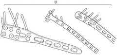
图1是包括处于复合角度的多个小螺纹孔的骨板的一组透视图。Figure 1 is a set of perspective views of a bone plate including a plurality of small threaded holes at compound angles.
图2是在三维体积中具有不同横截面形状、角度、深度和尺寸的多个孔的飞行器发动机叶片的透视图。Figure 2 is a perspective view of an aircraft engine blade having a plurality of holes of different cross-sectional shapes, angles, depths and sizes in a three-dimensional volume.
图3是根据一个实施例的包括用于测量圆柱形侧壁的45°镜尖端的光纤钻孔检查工具的混合框图和侧视图。3 is a hybrid block diagram and side view of a fiber optic drill inspection tool including a 45° mirror tip for measuring cylindrical sidewalls, according to one embodiment.
图4是根据一个实施例的可配置有一组可更换光学探头的非接触式光学测量设备的框图。4 is a block diagram of a non-contact optical measurement device that may be configured with a set of replaceable optical probes, according to one embodiment.
图5是根据一个实施例的探头尖端中的光学组合件的注释侧视图。5 is an annotated side view of an optical assembly in a probe tip according to one embodiment.
图6是根据一个实施例的注释系统框图。6 is a block diagram of an annotation system according to one embodiment.
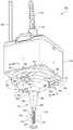
图7是根据一个实施例的配置有第一可更换光学探头的非接触式光学测量设备的等距视图。7 is an isometric view of a non-contact optical measurement device configured with a first replaceable optical probe according to one embodiment.
图8是沿图7中的线8-8截取的截面图。FIG. 8 is a cross-sectional view taken along line 8 - 8 in FIG. 7 .
图9和图10是表示为图像的点云的示意图,这些图像显示出使用图7和图8的配置有第一可更换光学探头的非接触式光学测量设备测量的M8螺纹。9 and 10 are schematic diagrams of point clouds represented as images showing M8 threads measured using the non-contact optical measurement device of FIGS. 7 and 8 configured with the first replaceable optical probe.
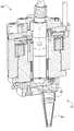
图11是根据一个实施例如图7和图8所示但配备有第二可更换光学探头的非接触式光学测量设备的等距视图。Figure 11 is an isometric view of the non-contact optical measurement device shown in Figures 7 and 8 but equipped with a second interchangeable optical probe, according to one embodiment.
图12是沿图11中的线12-12截取的截面图。FIG. 12 is a cross-sectional view taken along line 12 - 12 in FIG. 11 .
图13是使用图11和图12的配置有第二可更换光学探头的非接触式光学测量设备进行的二维扫描的点云的注释示意图。13 is an annotated schematic diagram of a point cloud of a two-dimensional scan using the non-contact optical measurement device of FIGS. 11 and 12 configured with a second interchangeable optical probe.
图14是执行齿圈的检查的第三可更换光学探头的俯视图。FIG. 14 is a top view of the third interchangeable optical probe that performs inspection of the ring gear.
图15是根据一个实施例配置有用于二维扫描的f-θ透镜的如图7和图8所示配备有第一可更换光学探头的非接触式光学测量设备的等距视图。15 is an isometric view of the non-contact optical measurement device equipped with the first interchangeable optical probe shown in FIGS. 7 and 8 configured with an f-theta lens for two-dimensional scanning, according to one embodiment.
具体实施方式Detailed ways
图1和图2示出具有多个小钻孔(bore)的设备的示例,每个小钻孔都将被快速检查。例如,图1示出三个骨板10。图2示出飞行器发动机叶片20。Figures 1 and 2 show an example of a device with multiple bores, each to be quickly inspected. For example, FIG. 1 shows three
图3示出光纤钻孔检查工具60,其被配置为将激光束62施加到圆柱形侧壁66的内表面64,该圆柱形侧壁66限定了钻孔76或其他被检查的孔洞。例如,根据一些实施例,内表面64可以是由支架限定的管的一部分。FIG. 3 shows a fiber optic borehole inspection tool 60 configured to apply a laser beam 62 to an
光纤钻孔检查工具60包括可旋转、可延伸和可替换的光学探头组合件80。在一些实施例中,光学探头组合件80包括具有内部90的套管88,激光束62从套管88的近端92和远端94被传送通过该内部90。套管88可选地容纳引导激光束62并接收从侧壁66的内表面64反射的光的光纤(未示出)。The fiber optic borehole inspection tool 60 includes a rotatable, extendable, and replaceable
在图3所示的示例中,诸如反射镜110之类的光学器件被安装在远端94处,以便将由激光源和准直模块(参见例如图6)轴向发射的光朝着内表面64横向转向。然后由内表面64反射的光被反射镜110沿轴向方向重新定向回来。In the example shown in FIG. 3 , optics such as
所接收和重定向的光通过光纤向套管88的近端92传播,在该点处,光在光传感器120处被捕获。在其他实施例中,光纤被自由空间、自由空间光学器件、多个光纤或这三者的组合替代。The received and redirected light travels through the optical fiber towards the
关于适用于传感器120的传感器,一些实施例可以包括干涉仪传感器。因此,激光束62的相位变化被用于获得宽度距离测量值(即内径(ID)测量值),如从反射镜110的位置到内表面64所测量的那样。在其他实施例中,如稍后参照图5和图6所解释,可以采用各种技术(例如,锥光全息术、低相干干涉仪(LCI)、彩色共焦等)来测量孔和其他几何特征。With regard to suitable sensors for
根据另一实施例,提供一种光学开关,使得两个或更多个传感器可以被切换以用于依次通过耦合到光学开关的输入侧上的光纤实施两种或更多种测量技术(例如,LCI、彩色共焦等)。这使得可以为开关的输出侧上的通用光学准直模块选择适当的技术。According to another embodiment, an optical switch is provided such that two or more sensors can be switched for implementing two or more measurement techniques (eg, two or more measurement techniques) in turn through an optical fiber coupled to the input side of the optical switch. LCI, color confocal, etc.). This makes it possible to select an appropriate technology for a generic optical collimation module on the output side of the switch.
为了测量内表面64(在一些实施例中包括可选的螺纹)的轮廓的尺寸,套管88是可旋转和可延伸的。技术人员将理解,有多种技术可用于实现组合件80与内表面64之间的相对运动。例如,通过旋转致动器系统130实现旋转。在一个实施例中,电机132旋转第一齿轮136,该第一齿轮136与第二齿轮140互相啮合并将旋转运动传递到第二齿轮140。第二齿轮140耦接到套管88以施加旋转。以旋转或弧形距离的形式对旋转量进行编码,从而可以将信息准确地映射到内表面64上的特征的方位角位置。类似地,线性平台150提供套管88的延伸和缩回。线性移动量也被编码以用于映射从内表面64检测或测量的特征的纵向位置。当同时应用旋转和线性移动时(例如,在插入或拔出光学探头组合件80时),执行螺旋检查。The
光学探头组合件80包括用于检查内表面64的反射镜110,而另一组合件没有这样的反射镜。因此,光被发射和轴向反射以检查钻孔的底壁表面。附加组合件还可用于其他专门的检查任务,例如底切部(undercuts)的检查。The
在一些实施例中,光学探头组合件80是一组可替换探头组合件的构件。例如,图4示出可配置有一组可更换光学探头162的非接触式光学测量设备160,每个光学探头具有专用于其功能的微型光学器件,以实现光学测量参数的配置和到测量部位的不同物理光束递送传播路径。因此,随着不同的光学探头162被更换,设备160被配置用于基于从光源170发射并被工件表面反射以入射到光谱传感器174(例如,彩色共焦、LCI和其他类型的光谱传感器)上的光的可配置光传播路径166来检测或测量不同的几何工件特征。In some embodiments, the
在一些实施例中,光源170和光谱传感器174是统称为传感器的单个模块。在其他实施例中,光源170和光谱传感器174是独立的模块。光源170和光谱传感器174的示例是可从德国Gaggenau的Precitec GmbH&Co.KG获得的CHR2IT DW。附加的示例在图6中示出。其他实施例可以使用激光。In some embodiments, light source 170 and
光源170和光谱传感器174可以远离准直器178定位并且与准直器178光纤耦合176以在准直器178与光源170和光谱传感器174之间提供相对窄的红外波段(1.07微米波长)光180。在一些实施例中,光源170和光谱传感器174不是远离准直器178定位,而是与准直器178和图4中所示的其他部件一起位于共同外壳中。还有其他实施例可以使用自由空间光学器件作为光纤176的替代品。光纤176的一个示例是可从Precitec GmbH&Co.KG获得的单模光纤。Light source 170 and
准直器178接收从光源170发射的光180并形成沿光轴190定向的准直光186。技术人员将理解,准直光186例如由于衍射而包括一些发散,并且可接受的发散量取决于所需的应用。准直器178的一个示例是可从新泽西州Newton的Thorlabs,Inc.获得的F260 APC-1064。
旋转运动台196被配置为引起围绕光轴190的旋转运动。换句话说,在准直空间中并且在光180被准直器178剪切之后,施加旋转运动。因此,这种剪切允许在准直空间中的完全360°(或更多)的自由旋转。此外,从固定的或可安装到旋转运动台196的自由空间光学器件的角度来看,准直光束200随着旋转运动传感器208(例如,编码器)被配置为(直接或间接)跟踪由旋转运动台196施加的可控旋转量而旋转。例如,跟踪可以包括确定旋转、方位角或任何其他形式的位置信息,这些位置信息可用于推导出已被采集光谱数据的空间位置。The
在一组可更换光学探头162中,每个构件包括与该组中的其他构件的探头光学配置不同的探头光学配置212,使得准直光束200可以从光轴190横向偏移,相对于光轴190以一定角度定向,或横向偏移和成角度的组合。因此,每个探头162随着可控旋转量被施加于探头光学配置而沿着相应的传播路径引导准直光200,使得准直光的反射部分被引导朝向光谱传感器174。因此,特定几何特征的测量通过可更换光学探头162相对于光轴190的精确运动而变得可能。In a set of replaceable
在图4的示例中,第一光束214与光轴190同轴(例如,用于钻孔深度测量)。第二光束218由位于探头的远端处的45°镜尖端以90°引导(参见例如图5、图7和图8)。第三光束228被从远端以向上的中间角引导(例如,用于测量底切部)。第四光束230被从近端以向下的中间角引导。第五光束236被从近端以直角发射。第六光束240从光轴190横向偏移并且被向下(或以另一角度)引导。从旋转光轴起的横向偏移也被称为径向偏移。In the example of FIG. 4, the
在一些实施例中,每种类型的光束传播路径由不同的探头建立。在另一实施例中,可以在重新配置其光学器件之后由通用探头提供两个或更多个光束。例如,可以插入反射镜以从光束214改变为光束218。此外,技术人员将理解,术语光束不需要排除在对表面进行采样时产生的一串脉冲。In some embodiments, each type of beam propagation path is established by a different probe. In another embodiment, two or more beams may be provided by the universal probe after reconfiguring its optics. For example, a mirror can be inserted to change from
安装装置246充当通用接口,以便该组可更换光学探头162的任何选定构件可拆卸地安装到旋转运动台196上。因此,各个探头尖端可以使用物理固位(retention)技术(例如磁性或真空耦合)通过通用精密接口可重复地附接到公共旋转运动轴(与光轴190同轴)。通用接口还实现各种探头尖端的自动更换。Mounting
在一些实施例中,旋转运动台196的旋转面上的高精度运动安装使得能够实现光学探头162相对于准直器178的旋转和探头162的自动更换。因此,该组可更换光学探头162的每个构件都可以容易地可拆卸地安装到旋转运动台196。精确的安装以及在准直空间中的旋转将探头的光轴相对于传感器174的光轴190和旋转运动轴线的未对准的不利影响最小化。In some embodiments, the high precision kinematic mounting on the surface of rotation of the
图5示出一个示例,其中在准直模块的下游,探头尖端242可以根据期望的测量规范进行光学配置。例如,在LCI的情况下,这将包括分束器和反射镜以在探头尖端内形成干涉仪的参考分支,并且包括球面或非球面聚焦透镜以获取准直光束并将其聚焦到一个光斑。对于彩色共焦,可以包括额外的光学器件以产生色散。在彩色共焦的情况下,探头尖端可以包括彩色透镜和反射元件。通过将透镜靠近测量部位放置在探头尖端中,可以实现较大的数值钻孔,从而减小光斑尺寸并提高分辨率。Figure 5 shows an example where, downstream of the collimation module, the
图6以框图的形式示出非接触式光学测量设备160。为简明起见,不再重复先前描述的部件的细节,并且结合图7-图15所示的实施例对探头162的附加细节进行注释和描述。例如,图7-图10示出用于使用同轴探头轴线和转向镜探头尖端测量圆柱形几何形状的探头250的示例;图11-图13示出用于使用圆形扫描和向下定向的径向偏移探头轴线测量平面几何形状的探头254的示例;图14示出用于使用横向定向(或成角度)的径向偏移探头轴线测量多面几何形状的探头260的示例;并且图15示出系统266的示例,该系统266包括探头268和f-θ透镜270,用于使用线性扫描和电流可调的探头尖端镜(例如,探头254的修改版本)来测量平面几何形状。当依次使用一组可更换光学探头162的不同构件来获取旋转和光谱信息时,复杂的几何形状是可测量的。FIG. 6 shows a non-contact
图6还示出基于来自旋转运动传感器208(图5)的位置信息274和来自光谱传感器174的光谱信息276生成几何表面的图像或点云(参见例如图9和图10)的处理设备272。处理设备272可以体现为远程定位的通用计算机、工作站、执行实时操作系统的嵌入式处理计算机、定制ASIC、FPGA、GPU或者被配置为从机器可读或计算机可读介质(例如,非暂时性机器可读存储介质)读取指令并执行本文描述的任何一种或多种方法的其他设备。在一些实施例中,处理设备272包括一个或多个处理器(或处理器核)、一个或多个存储器/存储设备以及一个或多个通信资源,其中的每一个都可以通过网络或总线通信地耦合。6 also shows a
图7和图8示出配备有探头250的非接触式光学测量设备280,其中图8示出的探头250包括探头光学配置284,其包括具有Mirau参考表面292的聚焦透镜290、用于形成在探头尖端310内的参考光束(未示出)和测量光束218的分束器300,以及90°转向镜314,该转向镜将光束218径向引导到钻孔326(图9和图10)的内壁320(图7、图9和图10),使得准直光200的反射部分330(图7)被引导朝向远程定位的光谱传感器(未显示)。在一些实施例中,探头250支持1mm到3mm弹跳的反射镜选项和其他角度。反射镜314是可移除的,或者它的位置是沿着尖端310或与尖端310一起可调节的。因此,可以控制以下光学参数:测量范围、工作距离和光斑尺寸。FIGS. 7 and 8 show a non-contact
图8还示出了旋转运动台196包括伺服旋转电机334,该伺服旋转电机334响应于由信号线338从控制电路(例如,处理设备272,图6)携带的控制信号执行空气轴承336(也被称为空气主轴)的旋转。控制信号也由一对光学编码器340从平台196提供,该对光学编码器340在电机334的相对侧上相互成角度地间隔开。光学编码器340是可从格洛斯特郡(Gloucestershire)Wotton-under-Edge的Renishaw plc获得的A4A1X30D10B。电机334顶部的编码器盘344生成用于跟踪由电机334施加的可控旋转量的可检测信号。编码器盘344是A-9405-4050,它也可从Renishaw plc获得。8 also shows that the
可包括磁性运动基座(mount)360,以用于在空气主轴336上更换探头162。例如,运动基座360包括运动底座(base)364(图7),该运动底座364具有三个工具球368,这三个工具球368围绕空气主轴336的底表面370相互成角度地间隔开。运动基座360还包括运动帽380,该运动帽380具有三对偏心安装销钉384,这些销钉也围绕探头162的上表面386(图8)相互成角度地间隔开。技术人员将理解,在另一实施例中,运动底座364可以位于探头162上并且运动帽380可以位于空气主轴336的底表面370上。A
每个偏心安装销钉384可围绕其纵向轴线旋转,以在手动配置步骤期间利用其偏心度来对准光学轴线和旋转轴线。例如,销钉384可以通过使用远端上的扳手将其旋转+/-180°来将工具球368上的接触点向上或向下调整0.2mm,以改善或调整运动帽380在运动底座364上的安置。Each
当安装在可从俄勒冈州Wilsonville的DWFritz Automation,Inc.获得的五轴ZeroTouch(零接触)运动和计量平台中时,非接触式光学测量设备280能够在测量体积内的任何一点和取向处进行六自由度运动和测量。该测量体积和五轴运动平台是Aqui等人的美国专利第10,598,521号的主题,该专利已转让给本申请人DWFritz Automation。因此,根据一个实施例,耦合到旋转运动台196的所谓伽马旋转轴线的直角探头250可以增强现有的计量系统。When mounted in a five-axis ZeroTouch motion and metrology platform available from DWFritz Automation, Inc. of Wilsonville, Oregon, the non-contact
图9和图10示出以由处理设备272(图6)生成的图像的形式生成点云的示例。随着探头250在钻孔326内旋转,反射光信息276(图6)的强度由传感器174采样并且位置信息274被用于确定采集采样强度的空间位置。本领域技术人员将理解,可以采用各种其他扫描或图像捕获技术。可以使用这些技术对各种其他类型的圆柱形几何形状(例如钻孔和其他螺纹孔)进行成像。此外,应当理解,在一些实施例中,施加给探头的可控旋转量可以包括对于一些检测和测量任务不旋转。例如,不需要旋转的静态探头可以包括单个共焦传感器,用于利用光束214(图4)来检查钻孔深度。9 and 10 illustrate examples of point clouds being generated in the form of images generated by processing device 272 (FIG. 6). As the
图11和图12示出配备有探头254的非接触式光学测量设备280。探头254包括0°探头尖端400,该探头尖端在光学系统的准直区域中通过反射镜402的两次连续90°反射而径向偏移。因此,平台196的旋转追踪圆形路径404(图11)以在与零件运动(例如飞刀)结合时实现快速二维扫描。这提供了优于二维激光三角测量的几个优点,包括通过测量范围的线性度、无阴影、多层厚度测量能力、更小的光斑尺寸,并且扫描圆的直径可以通过反射镜402相对于探头尖端400的布置被设定处于不同距离。例如,各种可滑动反射镜和尖端被考虑在内。11 and 12 show a non-contact
图13示出二维扫描416的示例表示。尖端400被旋转到其圆形光束路径上的各个位置,同时表面420在线性运动台(未示出)上线性移动422。可以通过探头尖端400的非线性角速度和用于数据采集的选择性触发来控制点云数据的均匀性。也可以通过旋转的选择性触发来避免冗余数据。例如,圆圈中的数字表示当从上到下扫描零件并且探头旋转时,将扫描区域划分为奇数列和偶数列。选择性触发使得能够在其旋转通过上半圆时进行奇数列的数据收集,而在其旋转通过下半圆时进行偶数列的数据收集。当零件被扫描时,这将产生比恒定触发率更均匀的点云密度。FIG. 13 shows an example representation of a two-
图14示出使用探头260扫描齿圈440的示例。探头260类似于探头254,但是包括90°探头尖端(或其他角度),其面朝着径向向外448、向内或处于中间角度。通常,当扫描齿圈时,探头被定位成局部垂直于在具有压力角的节圆(pitch circle)上的齿并且可能不平行于探头旋转轴线。因此,可以部署两个或更多个探头尖端来测量复杂的几何形状。FIG. 14 shows an example of scanning the
图15示出使用系统266进行的二维线性扫描的示例,该系统266包括f-θ透镜270、立方体分束器470、参考镜472和配备有探头268的非接触式光学测量设备280。探头268包括在位于f-θ透镜270的后焦点处的探头尖端478处的90°扫描镜476。透镜270由此充当单轴检流计。立方体分束器470将光束480分成从反射镜472表面反射的参考分支482和从工件表面(未示出)反射的测量分支486。当与工件表面的运动相结合时,测量分支486能够实现快速二维扫描。FIG. 15 shows an example of a two-dimensional linear
本领域技术人员现在将理解可以对上述实施例的细节进行许多改变而不背离本发明的基本原理。因此,本发明的范围应由权利要求和等效物来确定。Those skilled in the art will now understand that many changes may be made to the details of the above-described embodiments without departing from the underlying principles of the invention. Accordingly, the scope of the invention should be determined by the claims and equivalents.
Claims (17)
Applications Claiming Priority (3)
| Application Number | Priority Date | Filing Date | Title |
|---|---|---|---|
| US201962902311P | 2019-09-18 | 2019-09-18 | |
| US62/902,311 | 2019-09-18 | ||
| PCT/US2020/051475WO2021055736A1 (en) | 2019-09-18 | 2020-09-18 | Non-contact optical measurement devices and exchangeable optical probes |
Publications (1)
| Publication Number | Publication Date |
|---|---|
| CN114667432Atrue CN114667432A (en) | 2022-06-24 |
Family
ID=74883717
Family Applications (1)
| Application Number | Title | Priority Date | Filing Date |
|---|---|---|---|
| CN202080065715.9APendingCN114667432A (en) | 2019-09-18 | 2020-09-18 | Non-contact optical measuring device and interchangeable optical probe |
Country Status (8)
| Country | Link |
|---|---|
| US (1) | US20220373323A1 (en) |
| EP (1) | EP4018157A4 (en) |
| JP (1) | JP7434535B2 (en) |
| KR (1) | KR20220064994A (en) |
| CN (1) | CN114667432A (en) |
| CA (1) | CA3155008A1 (en) |
| MX (1) | MX2022003333A (en) |
| WO (1) | WO2021055736A1 (en) |
Cited By (2)
| Publication number | Priority date | Publication date | Assignee | Title |
|---|---|---|---|---|
| CN114199501A (en)* | 2021-12-20 | 2022-03-18 | 中国空气动力研究与发展中心空天技术研究所 | Two-degree-of-freedom electric pneumatic probe mounting support |
| CN116907369A (en)* | 2023-09-06 | 2023-10-20 | 太原科技大学 | Spiral welded pipe diameter laser detection system and application method thereof |
Families Citing this family (1)
| Publication number | Priority date | Publication date | Assignee | Title |
|---|---|---|---|---|
| DE102021208378A1 (en)* | 2021-08-03 | 2023-02-09 | Sms Group Gmbh | Arrangement for the optical measurement of a thread on an end of a metal pipe or on a socket and method for measurement |
Citations (11)
| Publication number | Priority date | Publication date | Assignee | Title |
|---|---|---|---|---|
| WO2006128733A2 (en)* | 2005-06-03 | 2006-12-07 | Werth Messtechnik Gmbh | Coordinate measuring unit and method for measuring an object with a coordinate measuring unit |
| CN101080608A (en)* | 2005-04-14 | 2007-11-28 | 松下电器产业株式会社 | Appearance inspection device and method |
| CN101166948A (en)* | 2005-04-26 | 2008-04-23 | 瑞尼斯豪公司 | Surface detection device with optical sensor |
| CN101802542A (en)* | 2007-09-14 | 2010-08-11 | 莱卡地球系统公开股份有限公司 | Method and measuring device for gauging surfaces |
| CN103424074A (en)* | 2012-05-25 | 2013-12-04 | 株式会社三丰 | Interchangeable optics configuration for a chromatic range sensor optical pen |
| US20150211850A1 (en)* | 2014-01-30 | 2015-07-30 | Mitutoyo Corporation | Interchangeable reflective assembly for a chromatic range sensor optical pen |
| CN105277152A (en)* | 2014-07-23 | 2016-01-27 | 特莎有限公司 | Probe holder for measuring system |
| CN107037444A (en)* | 2017-06-07 | 2017-08-11 | 深圳大学 | Optical system and laser radar |
| US20180017499A1 (en)* | 2015-06-08 | 2018-01-18 | National Research Council Of Canada | Real-time inspection of automated ribbon placement |
| JP2018205301A (en)* | 2017-06-06 | 2018-12-27 | 株式会社日立製作所 | Distance measuring device and three-dimensional shape measuring device. |
| CN109477714A (en)* | 2016-07-28 | 2019-03-15 | 瑞尼斯豪公司 | Contactless gauge head and operating method |
Family Cites Families (8)
| Publication number | Priority date | Publication date | Assignee | Title |
|---|---|---|---|---|
| US6668466B1 (en)* | 2000-10-19 | 2003-12-30 | Sandia Corporation | Highly accurate articulated coordinate measuring machine |
| US7881896B2 (en)* | 2002-02-14 | 2011-02-01 | Faro Technologies, Inc. | Portable coordinate measurement machine with integrated line laser scanner |
| US9739595B2 (en)* | 2008-12-11 | 2017-08-22 | Automated Precision Inc. | Multi-dimensional measuring system with measuring instrument having 360° angular working range |
| US8860952B2 (en)* | 2011-06-09 | 2014-10-14 | Quest Metrology, LLC | Optical thread profiler |
| US8736817B2 (en)* | 2012-05-25 | 2014-05-27 | Mitutoyo Corporation | Interchangeable chromatic range sensor probe for a coordinate measuring machine |
| US10254105B2 (en)* | 2016-12-05 | 2019-04-09 | Quality Vision International, Inc. | Exchangeable lens module system for probes of optical measuring machines |
| US10794688B2 (en)* | 2018-03-07 | 2020-10-06 | Mitutoyo Corporation | Optical interference measuring device |
| JP7193992B2 (en)* | 2018-11-28 | 2022-12-21 | 株式会社日立製作所 | Shape measuring system, probe tip, shape measuring method, and program |
- 2020
- 2020-09-18CNCN202080065715.9Apatent/CN114667432A/enactivePending
- 2020-09-18EPEP20864433.6Apatent/EP4018157A4/enactivePending
- 2020-09-18WOPCT/US2020/051475patent/WO2021055736A1/ennot_activeCeased
- 2020-09-18CACA3155008Apatent/CA3155008A1/enactivePending
- 2020-09-18KRKR1020227012269Apatent/KR20220064994A/enactivePending
- 2020-09-18JPJP2022517508Apatent/JP7434535B2/enactiveActive
- 2020-09-18USUS17/753,972patent/US20220373323A1/enactivePending
- 2020-09-18MXMX2022003333Apatent/MX2022003333A/enunknown
Patent Citations (11)
| Publication number | Priority date | Publication date | Assignee | Title |
|---|---|---|---|---|
| CN101080608A (en)* | 2005-04-14 | 2007-11-28 | 松下电器产业株式会社 | Appearance inspection device and method |
| CN101166948A (en)* | 2005-04-26 | 2008-04-23 | 瑞尼斯豪公司 | Surface detection device with optical sensor |
| WO2006128733A2 (en)* | 2005-06-03 | 2006-12-07 | Werth Messtechnik Gmbh | Coordinate measuring unit and method for measuring an object with a coordinate measuring unit |
| CN101802542A (en)* | 2007-09-14 | 2010-08-11 | 莱卡地球系统公开股份有限公司 | Method and measuring device for gauging surfaces |
| CN103424074A (en)* | 2012-05-25 | 2013-12-04 | 株式会社三丰 | Interchangeable optics configuration for a chromatic range sensor optical pen |
| US20150211850A1 (en)* | 2014-01-30 | 2015-07-30 | Mitutoyo Corporation | Interchangeable reflective assembly for a chromatic range sensor optical pen |
| CN105277152A (en)* | 2014-07-23 | 2016-01-27 | 特莎有限公司 | Probe holder for measuring system |
| US20180017499A1 (en)* | 2015-06-08 | 2018-01-18 | National Research Council Of Canada | Real-time inspection of automated ribbon placement |
| CN109477714A (en)* | 2016-07-28 | 2019-03-15 | 瑞尼斯豪公司 | Contactless gauge head and operating method |
| JP2018205301A (en)* | 2017-06-06 | 2018-12-27 | 株式会社日立製作所 | Distance measuring device and three-dimensional shape measuring device. |
| CN107037444A (en)* | 2017-06-07 | 2017-08-11 | 深圳大学 | Optical system and laser radar |
Cited By (4)
| Publication number | Priority date | Publication date | Assignee | Title |
|---|---|---|---|---|
| CN114199501A (en)* | 2021-12-20 | 2022-03-18 | 中国空气动力研究与发展中心空天技术研究所 | Two-degree-of-freedom electric pneumatic probe mounting support |
| CN114199501B (en)* | 2021-12-20 | 2023-04-25 | 中国空气动力研究与发展中心空天技术研究所 | Two-degree-of-freedom electric pneumatic probe mounting support |
| CN116907369A (en)* | 2023-09-06 | 2023-10-20 | 太原科技大学 | Spiral welded pipe diameter laser detection system and application method thereof |
| CN116907369B (en)* | 2023-09-06 | 2023-12-12 | 太原科技大学 | Spiral welded pipe diameter laser detection system and application method thereof |
Also Published As
| Publication number | Publication date |
|---|---|
| EP4018157A4 (en) | 2023-08-30 |
| EP4018157A1 (en) | 2022-06-29 |
| JP2022549181A (en) | 2022-11-24 |
| CA3155008A1 (en) | 2021-03-25 |
| KR20220064994A (en) | 2022-05-19 |
| JP7434535B2 (en) | 2024-02-20 |
| WO2021055736A1 (en) | 2021-03-25 |
| MX2022003333A (en) | 2022-05-16 |
| US20220373323A1 (en) | 2022-11-24 |
Similar Documents
| Publication | Publication Date | Title |
|---|---|---|
| US7903245B2 (en) | Multi-beam optical probe and system for dimensional measurement | |
| JP7005750B2 (en) | Coherence tomography optical device orientation devices, coherence tomography, and laser processing systems | |
| JP6256995B2 (en) | Coordinate measuring system and method | |
| CN105829828B (en) | Method for measuring penetration depth of laser beam into workpiece and laser processing equipment | |
| JP7434535B2 (en) | Non-contact optical measurement equipment and replaceable optical probes | |
| EP3702723B1 (en) | Apparatus and method for measuring a profile of an internally threaded surface | |
| JP2020051892A (en) | Measurement system and method for manufacturing shaft with hole | |
| WO2021187191A1 (en) | Inner surface shape measurement device, alignment method for inner surface shape measurement device, and magnification calibration method | |
| CN104913732A (en) | Normal-tracking-type aspheric surface measuring method and system based on composite laser interference | |
| CN109579782B (en) | High-precision large-working-distance auto-collimation three-dimensional angle measuring device and method | |
| CN117716201A (en) | A measurement and positioning system based on machine vision and laser triangulation | |
| US8593644B2 (en) | White light optical profilometer for measuring complex surfaces | |
| Tong et al. | A novel laser-based system for measuring internal thread parameters | |
| Zhang et al. | A system for measuring high-reflective sculptured surfaces using optical noncontact probe | |
| JP2021148770A (en) | Magnification calibration method for inner surface shape measuring machine, and inner surface shape measuring machine | |
| US20040263840A1 (en) | Calibration of reconfigurable inspection machine | |
| JP7058869B2 (en) | Optical imaging probe and optical measuring device | |
| CN109579778B (en) | Device and method for measuring three-dimensional angle based on dual-wavelength light splitting auto-collimation | |
| JP2019191417A (en) | Optical imaging probe | |
| TW201326737A (en) | Measuring system and method for morphology of hole surface | |
| JP2013253915A (en) | Lens surface interval measurement device | |
| JP4922905B2 (en) | Method and apparatus for measuring position variation of rotation center line | |
| CN115096209B (en) | Non-contact auxiliary positioning laser interferometry system | |
| TW202445096A (en) | Probe and shape measuring device | |
| JP2025108861A (en) | Grating projection device and shape measuring device equipped with same |
Legal Events
| Date | Code | Title | Description |
|---|---|---|---|
| PB01 | Publication | ||
| PB01 | Publication | ||
| SE01 | Entry into force of request for substantive examination | ||
| SE01 | Entry into force of request for substantive examination | ||
| TA01 | Transfer of patent application right | ||
| TA01 | Transfer of patent application right | Effective date of registration:20240724 Address after:U.S.A. Applicant after:Industrial Metrology Solutions Co.,Ltd. Country or region after:U.S.A. Address before:oregon Applicant before:Defritz automation Country or region before:U.S.A. |