CN114665273A - Dual-band millimeter wave planar antenna - Google Patents
Dual-band millimeter wave planar antennaDownload PDFInfo
- Publication number
- CN114665273A CN114665273ACN202210230718.4ACN202210230718ACN114665273ACN 114665273 ACN114665273 ACN 114665273ACN 202210230718 ACN202210230718 ACN 202210230718ACN 114665273 ACN114665273 ACN 114665273A
- Authority
- CN
- China
- Prior art keywords
- metal
- patch
- dual
- width
- planar antenna
- Prior art date
- Legal status (The legal status is an assumption and is not a legal conclusion. Google has not performed a legal analysis and makes no representation as to the accuracy of the status listed.)
- Granted
Links
- 239000002184metalSubstances0.000claimsabstractdescription116
- 229910052751metalInorganic materials0.000claimsabstractdescription116
- 230000005855radiationEffects0.000claimsabstractdescription56
- 239000000758substrateSubstances0.000claimsabstractdescription24
- 238000004891communicationMethods0.000abstractdescription5
- 238000004088simulationMethods0.000description8
- 238000010586diagramMethods0.000description3
- 238000000034methodMethods0.000description3
- 230000009286beneficial effectEffects0.000description2
- 238000013461designMethods0.000description2
- 238000001514detection methodMethods0.000description2
- 238000005516engineering processMethods0.000description2
- RYGMFSIKBFXOCR-UHFFFAOYSA-NCopperChemical compound[Cu]RYGMFSIKBFXOCR-UHFFFAOYSA-N0.000description1
- 229910052802copperInorganic materials0.000description1
- 239000010949copperSubstances0.000description1
- 230000008878couplingEffects0.000description1
- 238000010168coupling processMethods0.000description1
- 238000005859coupling reactionMethods0.000description1
- 238000011161developmentMethods0.000description1
- PCHJSUWPFVWCPO-UHFFFAOYSA-NgoldChemical compound[Au]PCHJSUWPFVWCPO-UHFFFAOYSA-N0.000description1
- 229910052737goldInorganic materials0.000description1
- 239000010931goldSubstances0.000description1
- 230000036541healthEffects0.000description1
- 230000010354integrationEffects0.000description1
- 238000002955isolationMethods0.000description1
- 238000012986modificationMethods0.000description1
- 230000004048modificationEffects0.000description1
- 238000005457optimizationMethods0.000description1
- 238000011160researchMethods0.000description1
- 239000013585weight reducing agentSubstances0.000description1
Images


Classifications
- H—ELECTRICITY
- H01—ELECTRIC ELEMENTS
- H01Q—ANTENNAS, i.e. RADIO AERIALS
- H01Q9/00—Electrically-short antennas having dimensions not more than twice the operating wavelength and consisting of conductive active radiating elements
- H01Q9/04—Resonant antennas
- H01Q9/0407—Substantially flat resonant element parallel to ground plane, e.g. patch antenna
- H01Q9/045—Substantially flat resonant element parallel to ground plane, e.g. patch antenna with particular feeding means
- H—ELECTRICITY
- H01—ELECTRIC ELEMENTS
- H01Q—ANTENNAS, i.e. RADIO AERIALS
- H01Q1/00—Details of, or arrangements associated with, antennas
- H01Q1/48—Earthing means; Earth screens; Counterpoises
- H—ELECTRICITY
- H01—ELECTRIC ELEMENTS
- H01Q—ANTENNAS, i.e. RADIO AERIALS
- H01Q1/00—Details of, or arrangements associated with, antennas
- H01Q1/52—Means for reducing coupling between antennas; Means for reducing coupling between an antenna and another structure
- H—ELECTRICITY
- H01—ELECTRIC ELEMENTS
- H01Q—ANTENNAS, i.e. RADIO AERIALS
- H01Q5/00—Arrangements for simultaneous operation of antennas on two or more different wavebands, e.g. dual-band or multi-band arrangements
- H01Q5/20—Arrangements for simultaneous operation of antennas on two or more different wavebands, e.g. dual-band or multi-band arrangements characterised by the operating wavebands
- H—ELECTRICITY
- H01—ELECTRIC ELEMENTS
- H01Q—ANTENNAS, i.e. RADIO AERIALS
- H01Q5/00—Arrangements for simultaneous operation of antennas on two or more different wavebands, e.g. dual-band or multi-band arrangements
- H01Q5/50—Feeding or matching arrangements for broad-band or multi-band operation
- H—ELECTRICITY
- H01—ELECTRIC ELEMENTS
- H01Q—ANTENNAS, i.e. RADIO AERIALS
- H01Q9/00—Electrically-short antennas having dimensions not more than twice the operating wavelength and consisting of conductive active radiating elements
- H01Q9/04—Resonant antennas
- H01Q9/0407—Substantially flat resonant element parallel to ground plane, e.g. patch antenna
Landscapes
- Waveguide Aerials (AREA)
Abstract
Translated fromChinese
Description
Translated fromChinese技术领域technical field
本申请属于毫米波平面技术领域,尤其涉及一种双频段毫米波平面天线。The present application belongs to the technical field of millimeter wave planes, and in particular relates to a dual-band millimeter wave plane antenna.
背景技术Background technique
毫米波是指波长在毫米量级的电磁波,因为其频率较高,绝对带宽较大,波长较短,探测精确更高,毫米波器件更易小型化等诸多优点而受到越来越多的关注。近年来,随着毫米波集成电路的迅猛发展,毫米波的应用场景也愈发广泛,例如,车载毫米波雷达、毫米波健康检测等。Millimeter waves refer to electromagnetic waves with wavelengths in the order of millimeters. They have attracted more and more attention due to their higher frequency, larger absolute bandwidth, shorter wavelength, higher detection accuracy, and easier miniaturization of millimeter wave devices. In recent years, with the rapid development of millimeter-wave integrated circuits, the application scenarios of millimeter-wave have become more and more extensive, such as vehicle-mounted millimeter-wave radar, millimeter-wave health detection, etc.
但是,若要实现将PCB电路板和天线的集成,从而实现低成本、结构紧凑的毫米波无线通信系统,毫米波平面天线的设计就显得尤为重要,同样,毫米波天线的设计也是目前学术界和工业界研究的热点之一。However, in order to realize the integration of the PCB circuit board and the antenna, so as to realize a low-cost and compact millimeter-wave wireless communication system, the design of the millimeter-wave planar antenna is particularly important. and one of the hotspots of industrial research.
现有的毫米波平面天线,采用的是三片贴片级联的形式,但是只能在单一频段工作,不具有多频段的特性。对于多频段的毫米波应用场景,现有的技术不能完全适用,甚至还可能影响系统的整体性能。在需要同时覆盖多个频段时,例如需要63.5GHz和77GHz两个频段,则需要额外增加一个工作频段的新天线,导致增加了天线的数量,增强了天线间的互耦,增加了系统复杂性和成本。The existing millimeter-wave planar antenna adopts the form of three-piece patch cascade, but it can only work in a single frequency band and does not have the characteristics of multiple frequency bands. For multi-band millimeter wave application scenarios, existing technologies cannot be fully applied, and may even affect the overall performance of the system. When multiple frequency bands need to be covered at the same time, for example, two frequency bands of 63.5GHz and 77GHz are required, a new antenna in the working frequency band needs to be added, which increases the number of antennas, enhances the mutual coupling between antennas, and increases the complexity of the system. and cost.
发明内容SUMMARY OF THE INVENTION
本申请的目的是提供一种双频段毫米波平面天线,以满足多频段的毫米波应用场景,降低成本。The purpose of this application is to provide a dual-band millimeter-wave planar antenna to meet multi-band millimeter-wave application scenarios and reduce costs.
为了实现上述目的,本申请技术方案如下:In order to achieve the above purpose, the technical solutions of the present application are as follows:
一种双频段毫米波平面天线,包括介质基板、设置在所述介质基板上表面的金属辐射贴片、设置在所述介质基板下表面的金属地板,以及馈线,所述金属辐射贴片包括矩形且长宽尺寸相同的第一金属辐射贴片、第二金属辐射贴片和第三金属辐射贴片,所述第二金属辐射贴片和第三金属辐射贴片各个角设置有对称的L形槽,所述第三金属辐射贴片与所述馈线的连接部设置有凹槽。A dual-band millimeter-wave planar antenna, comprising a dielectric substrate, a metal radiating patch arranged on the upper surface of the dielectric substrate, a metal floor arranged on the lower surface of the dielectric substrate, and a feeder, the metal radiating patch comprising a rectangular And the first metal radiation patch, the second metal radiation patch and the third metal radiation patch with the same length and width, the second metal radiation patch and the third metal radiation patch are provided with symmetrical L-shapes at each corner A groove is provided at the connection part of the third metal radiation patch and the feeder.
进一步的,所述馈线远离所述金属辐射贴片的一端的宽度大于用于连接所述金属辐射贴片的一端的宽度。Further, the width of one end of the feed line away from the metal radiating patch is greater than the width of one end used to connect the metal radiating patch.
进一步的,所述馈线远离所述金属辐射贴片的一端的宽度为0.18毫米,连接所述金属辐射贴片的一端的宽度为0.1毫米。Further, the width of one end of the feed line away from the metal radiation patch is 0.18 mm, and the width of the end connected to the metal radiation patch is 0.1 mm.
进一步的,所述馈线宽度小的一端包括用于连接所述第一金属辐射贴片的第一段、用于连接所述第二金属辐射贴片的第二段和用于连接所述第三金属辐射贴片的第三段,所述第二段的长度大于第一段,所述第三段的长度小于第一段。Further, an end with a smaller width of the feed line includes a first section for connecting the first metal radiating patch, a second section for connecting the second metal radiating patch, and a second section for connecting the third metal radiating patch. In the third segment of the metal radiation patch, the length of the second segment is greater than that of the first segment, and the length of the third segment is shorter than that of the first segment.
进一步的,所述第一段的长度为1.13毫米,所述第二段的长度为1.23毫米,所述第三段的长度为1.1毫米。Further, the length of the first section is 1.13 mm, the length of the second section is 1.23 mm, and the length of the third section is 1.1 mm.
进一步的,所述介质基板上表面对应所述馈线远离所述金属辐射贴片的一端设置有表层金属地面板,所述表层金属地面板位于所述馈线的两侧,形成便于所述馈线经过的缺口。Further, a surface metal ground plate is provided on the upper surface of the dielectric substrate corresponding to the end of the feeder away from the metal radiation patch, and the surface metal ground plate is located on both sides of the feeder, forming a convenient passage for the feeder to pass through. gap.
进一步的,所述缺口的宽度为0.522毫米,所述表层金属地面板的宽度为1.23毫米。Further, the width of the gap is 0.522 mm, and the width of the surface metal floor panel is 1.23 mm.
进一步的,所述表层金属地面板上设置有若干与所述金属地板连接的金属化过孔。Further, a plurality of metallized vias connected to the metal floor are provided on the surface metal floor.
进一步的,所述L形槽自所述第二金属辐射贴片或第三金属辐射贴片任意一个长边上下两侧,向贴片内部延伸并向贴片中部延伸,所述第二金属辐射贴片或第三金属辐射贴片的L形槽沿贴片两个中线两两对称。Further, the L-shaped groove extends from the upper and lower sides of any one long side of the second metal radiation patch or the third metal radiation patch to the interior of the patch and to the middle of the patch, the second metal radiation patch. The L-shaped grooves of the patch or the third metal radiating patch are symmetrical along the two midlines of the patch.
进一步的,所述L形槽的宽度为0.05毫米,所述L形槽向贴片内部延伸的横向宽度为0.26毫米,所述L形槽向贴片中部延伸的纵向宽度为0.3毫米,所述L形槽与金属辐射贴片短边边缘之间的距离为0.03毫米。Further, the width of the L-shaped groove is 0.05 mm, the lateral width of the L-shaped groove extending to the interior of the patch is 0.26 mm, the longitudinal width of the L-shaped groove extending to the middle of the patch is 0.3 mm, and the The distance between the L-shaped groove and the short edge of the metal radiating patch is 0.03 mm.
本申请提出的一种双频段毫米波平面天线,可以同时覆盖63.5GHz和77GHz两个频段,并且方向图具有较好的一致性,可以广泛应用于多频段毫米波通信的场景。本申请主要是利用微带贴片天线开槽的方法,实现了一种工作于毫米波频段的多频段平面天线,开槽的方法主要会影响贴片天线辐射体上的电流分布,进而影响天线的辐射特性以及工作频段。本申请设计的天线可以同时工作于63.5GHz和77GHz两个频段,这与现阶段常见的毫米波器件的工作频率是吻合的。也就是说,这样一副天线就可以解决双频段毫米波通信的需求,也就在一定程度上减少了天线数量,降低了系统复杂性,便于产品的小型化,提升了系统整体的可靠性。并且该天线工作于不同频段时的辐射方向图也具有良好的一致性,所以在实际投入使用时,不需要对产品的使用场景和工作模式可能对天线性能的影响做过多的额外考虑,所以这就有助于进一步提高系统的稳定性和可靠性。The dual-band millimeter-wave planar antenna proposed in this application can cover two frequency bands of 63.5GHz and 77GHz at the same time, and the pattern has good consistency, and can be widely used in multi-band millimeter-wave communication scenarios. This application mainly uses the method of slotting a microstrip patch antenna to realize a multi-band planar antenna operating in the millimeter wave frequency band. The slotting method mainly affects the current distribution on the radiator of the patch antenna, which in turn affects the antenna. radiation characteristics and operating frequency bands. The antenna designed in this application can work in two frequency bands of 63.5GHz and 77GHz at the same time, which is consistent with the working frequency of common millimeter wave devices at this stage. In other words, such a pair of antennas can meet the needs of dual-band millimeter-wave communication, which reduces the number of antennas to a certain extent, reduces the complexity of the system, facilitates the miniaturization of products, and improves the overall reliability of the system. And the radiation pattern of the antenna working in different frequency bands also has good consistency, so when it is actually put into use, there is no need to do too much additional consideration to the impact of the product's usage scenarios and working modes on the antenna performance, so This helps to further improve the stability and reliability of the system.
附图说明Description of drawings
图1为本申请一种双频段毫米波平面天线结构示意图;1 is a schematic structural diagram of a dual-band millimeter-wave planar antenna of the application;
图2为本申请实施例双频段毫米波平面天线尺寸示意图;2 is a schematic diagram of the dimensions of a dual-band millimeter-wave planar antenna according to an embodiment of the present application;
图3为本申请实施例金属辐射贴片尺寸示意图;3 is a schematic diagram of the size of a metal radiation patch according to an embodiment of the present application;
图4为本申请平面天线回波损耗曲线;Fig. 4 is the return loss curve of the planar antenna of the present application;
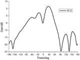
图5为本申请平面天线77GHz的E面方向图;Fig. 5 is the E-plane pattern of the plane antenna 77GHz of the present application;
图6为本申请平面天线77GHz的H面方向图;Fig. 6 is the H-plane pattern of the plane antenna 77GHz of the present application;
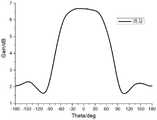
图7为本申请平面天线63.5GHz的E面方向图;FIG. 7 is an E-plane pattern of the planar antenna 63.5GHz of the present application;
图8为本申请平面天线63.5GHz的H面方向图。FIG. 8 is an H-plane pattern of the 63.5 GHz planar antenna of the present application.
具体实施方式Detailed ways
为了使本申请的目的、技术方案及优点更加清楚明白,以下结合附图及实施例,对本申请进行进一步详细说明。应当理解,此处描述的具体实施例仅用以解释本申请,并不用于限定本申请。In order to make the purpose, technical solutions and advantages of the present application more clearly understood, the present application will be described in further detail below with reference to the accompanying drawings and embodiments. It should be understood that the specific embodiments described herein are only used to explain the present application, but not to limit the present application.
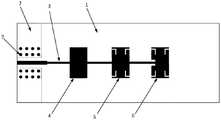
在一个实施例中,如图1所示,本申请一种双频段毫米波平面天线,包括介质基板1、设置在所述介质基板1上表面的金属辐射贴片、设置在所述介质基板1下表面的金属地板,以及馈线3。In one embodiment, as shown in FIG. 1 , a dual-band millimeter-wave planar antenna of the present application includes a
对于平面天线来说,金属辐射贴片设置在介质基板1的上表面,以电磁波能量的形式发射或接收电磁波能量,特别是无线电毫米波信号。金属辐射贴片(简称贴片)采用印刷电路板技术印制在介质基板1的中间部位。优选的,金属辐射贴片采用辐射性能较好的金属片形成,如铜或者金等。介质基板1未绝缘薄板,用于承载金属辐射贴片,介质基板1优选的采用介电常数较低的介质板,较低的介电常数有利于增加天线带宽。在一个具体的实施例中,介质基板1的介电常数为3.66,损耗角正切是0.0015。For a planar antenna, the metal radiating patch is arranged on the upper surface of the
金属地板的大小和介质基板1的大小相同,金属地板位于介质基板1的下表面,图1为俯视图,未示出金属地板。The size of the metal floor is the same as that of the
在一个优选的具体实施例中,介质基板1的宽度为10.52mm,长度为24.08mm,厚度为0.25mm。In a preferred specific embodiment, the width of the
而馈线3用于为金属辐射贴片提供信号馈电,为了便于连接外部信号,馈线3远离金属辐射贴片的一端一般沿着介质基板1长度方向的一个边沿向金属辐射贴片方向延伸。当有多个金属辐射贴片时,金属辐射贴片之间也通过馈线连接。The
在本实施例中,所述金属辐射贴片包括矩形且长宽尺寸相同的第一金属辐射贴片4、第二金属辐射贴片5和第三金属辐射贴片6,所述第二金属辐射贴片5和第三金属辐射贴片6各个角设置有对称的L形槽,所述第三金属辐射贴片6与所述馈线3的连接部设置有凹槽。In this embodiment, the metal radiation patch includes a rectangular first
本实施例设置有三个大小相同的矩形金属辐射贴片,第一金属辐射贴片4为一个完整的金属贴片,在其上方并没有设置任何缺口或图形形状。第二金属辐射贴片5的外形也是矩形,与第一金属辐射贴片4不同的是,第二金属辐射贴片5的任意一个长边上下两侧,在距离两个短边预设距离的位置分别向内开设有一个条形槽,条形槽向贴片内部延伸后并向贴片中部延伸,形成一个L形槽。形成的四个L形槽分别沿贴片两个中线两两对称。同样的,第三金属辐射贴片6各个角设置有对称的L形槽,与第二金属辐射贴片5的L形槽一致。This embodiment is provided with three rectangular metal radiating patches of the same size, and the first
本实施例开槽采用L形槽,可以改变贴片上的电流分布,以便形成双频段工作特性。In this embodiment, an L-shaped slot is used for slotting, and the current distribution on the patch can be changed, so as to form a dual-band operating characteristic.
所不同的是,如图3所示,第三金属辐射贴片6相比第二金属辐射贴片5,在面向馈线3的一侧长边上还设置有一凹槽,馈线3穿过该凹槽的中部与第三金属辐射贴片6连接。本实施例凹槽的作用主要是用于馈线和金属贴片的阻抗匹配。The difference is that, as shown in FIG. 3 , compared with the second
在一个具体的实施例中,如图2、图3所示,金属辐射贴片的长度P_L为1.55mm,宽度P_W为0.88mm。L形槽的宽度为G_H为0.05mm,L形槽向贴片内部延伸的横向宽度G_L_X为0.26mm,L形槽向贴片中部延伸的纵向宽度G_L_Y为0.3mm。L形槽与金属辐射贴片短边边缘之间的距离G_W为0.03mm。In a specific embodiment, as shown in FIG. 2 and FIG. 3 , the length P_L of the metal radiation patch is 1.55 mm, and the width P_W is 0.88 mm. The width of the L-shaped groove G_H is 0.05mm, the lateral width G_L_X of the L-shaped groove extending to the interior of the patch is 0.26mm, and the longitudinal width G_L_Y of the L-shaped groove extending to the middle of the patch is 0.3mm. The distance G_W between the L-shaped groove and the short edge of the metal radiating patch is 0.03mm.
第三金属辐射贴片6凹槽的深度P3_G_W为0.2mm,凹槽的长度为0.3mm。馈线3经过凹槽与第三金属辐射贴片连接,凹槽的两边距离馈线3的距离P3_G_L为0.1mm。The depth P3_G_W of the groove of the third
在一个具体的实施例中,所述馈线3远离所述金属辐射贴片的一端的宽度大于用于连接所述金属辐射贴片的一端的宽度。In a specific embodiment, the width of one end of the
为了便于连接外部馈电信号,本实施例馈线3用于连接外部馈电信号的部分宽度大于用于连接金属辐射贴片的部分。如图2所示,馈线3用于连接外部馈电信号的部分宽度F_W1为0.18mm(毫米);用于连接金属辐射贴片的部分较窄,其宽度F_W2为0.1mm。本实施例馈线3的不同宽度是用来进行阻抗匹配,馈线3较宽的一端的特性阻抗应控制在50欧姆左右。In order to facilitate the connection of the external feed signal, the width of the portion of the
在一个具体的实施例中,所述馈线3宽度小的一端包括用于连接所述第一金属辐射贴片4的第一段、用于连接所述第二金属辐射贴片5的第二段和用于连接所述第三金属辐射贴片6的第三段,所述第二段的长度大于第一段,所述第三段的长度小于第一段。In a specific embodiment, an end with a smaller width of the
如图2所示,第一段的长度F_W2_L1为1.13mm,第二段的长度F_W2_L2为1.23mm,第三段的长度F_W2_L3为1.1mm。As shown in FIG. 2 , the length F_W2_L1 of the first segment is 1.13 mm, the length F_W2_L2 of the second segment is 1.23 mm, and the length F_W2_L3 of the third segment is 1.1 mm.
需要说明的是,馈线3各段的具体长度是仿真优化的结果,上述实施例仅为一个具体的实例,本领域技术人员可以根据实际的应用需要进行优化。It should be noted that the specific length of each section of the
在另一个具体的实施例中,所述介质基板1上表面对应所述馈线3远离所述金属辐射贴片的一端设置有表层金属地面板2,所述表层金属地面板2位于所述馈线3的两侧,形成便于所述馈线3经过的缺口。In another specific embodiment, the upper surface of the
如图2所示,表层金属地面板2位于馈线3的两侧,其宽度W_TOP_GND为1.23mm。表层金属地面板2中间的缺口宽度G_F为0.522mm。As shown in FIG. 2 , the surface
在另一个具体的实施例中,所述表层金属地面板2上设置有若干与所述金属地板连接的金属化过孔7。In another specific embodiment, the surface
如图2所示,金属化过孔7的直径R_V是0.15mm。表层金属地面板2以及金属化过孔的存在主要是考虑高频PCB设计时,需要尽量提高走线之间的隔离度,表层金属地面板的存在会减少走线之间的串扰。As shown in FIG. 2 , the diameter R_V of the metallized via 7 is 0.15 mm. The existence of the surface
本申请双频段毫米波平面天线回波损耗曲线如图4所示,从仿真结果图中可以看到,在63.5GHz和77GHz的频点上,天线的回波损耗均小于-10dB,满足天线在这些频点的工作需求。The return loss curve of the dual-band millimeter-wave planar antenna of this application is shown in Figure 4. It can be seen from the simulation results that at the frequency points of 63.5GHz and 77GHz, the return loss of the antenna is less than -10dB, which satisfies The working requirements of these frequencies.
本申请双频段毫米波平面天线在77GHz仿真得到的方向图如图5和图6所示,其中图5是仿真得到的E面方向图,可以看到天线在77GHz的最大辐射方向在Theta=2°时,基本就是在天线阵面的法线方向,并且天线的最大增益约为7.7dB。图6是仿真得到的天线在77GHz的H面方向图,可以看到H面的增大辐射方向仍然在天线阵面的法线方向,H面的最大增益也约为7.7dB,H面的3dB波瓣宽度约为100°。The patterns obtained by the simulation of the dual-band millimeter-wave planar antenna of the present application at 77GHz are shown in Figures 5 and 6, of which Figure 5 is the pattern of the E-plane obtained by simulation. It can be seen that the maximum radiation direction of the antenna at 77GHz is at Theta=2 When °, it is basically in the normal direction of the antenna front, and the maximum gain of the antenna is about 7.7dB. Figure 6 is the H-plane pattern of the simulated antenna at 77GHz. It can be seen that the increased radiation direction of the H-plane is still in the normal direction of the antenna front. The maximum gain of the H-plane is also about 7.7dB, and the H-plane is 3dB. The lobe width is about 100°.
本申请双频段毫米波平面天线在63.5GHz仿真得到的方向图如图7和图8所示。其中图7是仿真得到的E面方向图,可以看到天线在63.5GHz的最大辐射大约在Theta=26°时,即最大辐射方向相比于天线阵面的法线方向发生了稍微的偏转,天线的最大增益约为6.7dB。图8是仿真得到的Theta=26°平面的天线方向图,在该平面内,天线的最大增益仍然约为6.7dB,并且在该平面内的天线波瓣宽度约为150°,可以实现较好的覆盖范围。The patterns obtained by the simulation of the dual-band millimeter-wave planar antenna of the present application at 63.5 GHz are shown in FIG. 7 and FIG. 8 . Figure 7 is the E-plane pattern obtained by simulation. It can be seen that the maximum radiation of the antenna at 63.5GHz is about Theta=26°, that is, the maximum radiation direction is slightly deflected compared to the normal direction of the antenna front. The maximum gain of the antenna is about 6.7dB. Figure 8 is the antenna pattern of the plane Theta=26° obtained by simulation. In this plane, the maximum gain of the antenna is still about 6.7dB, and the antenna lobe width in this plane is about 150°, which can achieve better coverage.
根据上述仿真结果,表明本申请双频段毫米波平面天线可以实现双频段工作特性,并且在63.5GHz和77GHz的辐射方向图具有较好的一致性,这对于毫米波无线通信产品的实际使用具有重要的意义。本申请在低剖面和不额外增加天线尺寸的前提下,实现了双频段的工作特性,对于毫米波双频段工作需求的应用场景,可以减少天线的使用数量,另外,毫米波平面天线的形式,也非常便于天线与PCB电路板的集成,这就有利于降低系统复杂性和成本,从而实现产品的小型化、轻量化,以及提高系统的稳定性。According to the above simulation results, it is shown that the dual-band millimeter-wave planar antenna of the present application can achieve dual-band operating characteristics, and the radiation patterns at 63.5GHz and 77GHz have good consistency, which is important for the practical use of millimeter-wave wireless communication products. meaning. The application achieves dual-band operation characteristics under the premise of low profile and no additional antenna size. For the application scenarios of millimeter-wave dual-band operation requirements, the number of antennas used can be reduced. In addition, the form of millimeter-wave planar antenna, It is also very convenient to integrate the antenna with the PCB circuit board, which is beneficial to reduce the complexity and cost of the system, thereby realizing the miniaturization and weight reduction of the product, and improving the stability of the system.
需要说明的是,本申请实施例中给出了一些具体的尺寸,仅仅是在所述频段工作性能较好的一种特殊情况。本申请属于共面波导的结构,主要通过控制馈线的线宽和馈线与两侧金属地的距离来控制馈线的特性阻抗。然而本领域技术人员容易理解的是,本领域技术人员可以根据具体的频段和方向图要求,对上述尺寸进行适应的调整,以满足所设计天线的增益和方向图需求。It should be noted that some specific dimensions are given in the embodiments of the present application, which are only a special case where the working performance is better in the frequency band. The present application belongs to the structure of the coplanar waveguide, and the characteristic impedance of the feeder is mainly controlled by controlling the line width of the feeder and the distance between the feeder and the metal ground on both sides. However, those skilled in the art can easily understand that, those skilled in the art can adjust the above dimensions according to specific frequency band and pattern requirements, so as to meet the gain and pattern requirements of the designed antenna.
以上所述实施例仅表达了本申请的几种实施方式,其描述较为具体和详细,但并不能因此而理解为对发明专利范围的限制。应当指出的是,对于本领域的普通技术人员来说,在不脱离本申请构思的前提下,还可以做出若干变形和改进,这些都属于本申请的保护范围。因此,本申请专利的保护范围应以所附权利要求为准。The above-mentioned embodiments only represent several embodiments of the present application, and the descriptions thereof are specific and detailed, but should not be construed as a limitation on the scope of the invention patent. It should be pointed out that for those skilled in the art, without departing from the concept of the present application, several modifications and improvements can be made, which all belong to the protection scope of the present application. Therefore, the scope of protection of the patent of the present application shall be subject to the appended claims.
Claims (10)
Priority Applications (1)
| Application Number | Priority Date | Filing Date | Title |
|---|---|---|---|
| CN202210230718.4ACN114665273B (en) | 2022-03-10 | 2022-03-10 | Dual-band millimeter wave planar antenna |
Applications Claiming Priority (1)
| Application Number | Priority Date | Filing Date | Title |
|---|---|---|---|
| CN202210230718.4ACN114665273B (en) | 2022-03-10 | 2022-03-10 | Dual-band millimeter wave planar antenna |
Publications (2)
| Publication Number | Publication Date |
|---|---|
| CN114665273Atrue CN114665273A (en) | 2022-06-24 |
| CN114665273B CN114665273B (en) | 2024-11-22 |
Family
ID=82030265
Family Applications (1)
| Application Number | Title | Priority Date | Filing Date |
|---|---|---|---|
| CN202210230718.4AActiveCN114665273B (en) | 2022-03-10 | 2022-03-10 | Dual-band millimeter wave planar antenna |
Country Status (1)
| Country | Link |
|---|---|
| CN (1) | CN114665273B (en) |
Citations (9)
| Publication number | Priority date | Publication date | Assignee | Title |
|---|---|---|---|---|
| CN101267063A (en)* | 2007-11-19 | 2008-09-17 | 哈尔滨工业大学 | A millimeter-wave band 4×4 conical conformal dual-band microstrip antenna and its design method |
| CN102057536A (en)* | 2008-04-04 | 2011-05-11 | 雷斯潘公司 | Single-feed multi-cell metamaterial antenna devices |
| CN209001122U (en)* | 2018-10-31 | 2019-06-18 | 南通至晟微电子技术有限公司 | The double array antennas of 5G millimeter wave two-band |
| CN110165399A (en)* | 2019-05-29 | 2019-08-23 | 中天宽带技术有限公司 | The dual-band antenna and electronic equipment of single port feed |
| CN110311219A (en)* | 2019-07-18 | 2019-10-08 | 中国电子科技集团公司第三十八研究所 | A serial-fed microstrip array antenna and system for millimeter-wave radar |
| CN210607637U (en)* | 2019-12-03 | 2020-05-22 | 上海航天电子有限公司 | Microstrip slot patch antenna |
| US20210249769A1 (en)* | 2018-06-12 | 2021-08-12 | Iee International Electronics & Engineering S.A. | Antenna array system for monitoring vital signs of people |
| CN114069190A (en)* | 2020-08-07 | 2022-02-18 | 福耀玻璃工业集团股份有限公司 | A circularly polarized microstrip antenna, OBU device and vehicle glass |
| CN114069214A (en)* | 2021-11-18 | 2022-02-18 | 安徽大学 | 5G millimeter wave dual-band antenna based on dual-ring structure |
- 2022
- 2022-03-10CNCN202210230718.4Apatent/CN114665273B/enactiveActive
Patent Citations (9)
| Publication number | Priority date | Publication date | Assignee | Title |
|---|---|---|---|---|
| CN101267063A (en)* | 2007-11-19 | 2008-09-17 | 哈尔滨工业大学 | A millimeter-wave band 4×4 conical conformal dual-band microstrip antenna and its design method |
| CN102057536A (en)* | 2008-04-04 | 2011-05-11 | 雷斯潘公司 | Single-feed multi-cell metamaterial antenna devices |
| US20210249769A1 (en)* | 2018-06-12 | 2021-08-12 | Iee International Electronics & Engineering S.A. | Antenna array system for monitoring vital signs of people |
| CN209001122U (en)* | 2018-10-31 | 2019-06-18 | 南通至晟微电子技术有限公司 | The double array antennas of 5G millimeter wave two-band |
| CN110165399A (en)* | 2019-05-29 | 2019-08-23 | 中天宽带技术有限公司 | The dual-band antenna and electronic equipment of single port feed |
| CN110311219A (en)* | 2019-07-18 | 2019-10-08 | 中国电子科技集团公司第三十八研究所 | A serial-fed microstrip array antenna and system for millimeter-wave radar |
| CN210607637U (en)* | 2019-12-03 | 2020-05-22 | 上海航天电子有限公司 | Microstrip slot patch antenna |
| CN114069190A (en)* | 2020-08-07 | 2022-02-18 | 福耀玻璃工业集团股份有限公司 | A circularly polarized microstrip antenna, OBU device and vehicle glass |
| CN114069214A (en)* | 2021-11-18 | 2022-02-18 | 安徽大学 | 5G millimeter wave dual-band antenna based on dual-ring structure |
Non-Patent Citations (3)
| Title |
|---|
| ANDREAS R. DIEWALD ET AL: "Radar target simulator with complex-valued delay line modeling based on standard radar components", 《ADVANCES IN RADIO SCIENCE》, 31 December 2018 (2018-12-31), pages 203 - 213* |
| G. VISWANADH RAVITEJA ET AL: "Defected Ground Structured Microstrip Patch Antenna with Quad L – Shaped Slot for Gain Enhancement at 4.8 GHz Frequency", 《COMMUNICATIONS ON APPLIED ELECTRONICS (CAE)》, vol. 7, no. 21, 31 October 2018 (2018-10-31), pages 1 - 6* |
| RUI-HU WEN ET AL: "Design of dual band millimeter wave beam shaped array antenna", 《2021 13TH INTERNATIONAL SYMPOSIUM ON ANTENNAS, PROPAGATION AND EM THEORY (ISAPE)》, 4 December 2021 (2021-12-04), pages 1 - 3, XP034114330, DOI: 10.1109/ISAPE54070.2021.9753285* |
Also Published As
| Publication number | Publication date |
|---|---|
| CN114665273B (en) | 2024-11-22 |
Similar Documents
| Publication | Publication Date | Title |
|---|---|---|
| KR100675383B1 (en) | Ultra-Small Wideband Microstrip Antenna | |
| CN114552210B (en) | Low-profile millimeter wave filtering antenna | |
| CN205752538U (en) | A dual-band planar monopole antenna fed by a symmetrical double-ring structure coplanar waveguide | |
| CN110311219A (en) | A serial-fed microstrip array antenna and system for millimeter-wave radar | |
| CN104157978B (en) | A kind of corner-fed high isolation dual polarized stacked microstrip antenna of modified model | |
| CN107634337B (en) | Patch Array Antenna Based on Soft Surface Structure | |
| CN108736153B (en) | Three-frequency low-profile patch antenna | |
| WO2019223318A1 (en) | Indoor base station and pifa antenna thereof | |
| CN106450726A (en) | Broadband slotted end-fire microstrip antenna | |
| CN112635994A (en) | Microstrip series feed antenna and millimeter wave radar | |
| CN115714257A (en) | LTCC-based miniaturized low-profile circularly polarized antenna and application | |
| CN110165401A (en) | Integral substrate gap waveguide feed gaps couple super surface circular polarized antenna | |
| CN111180877B (en) | A substrate-integrated waveguide horn antenna and its control method | |
| CN116130946A (en) | A dual-notch high-isolation ultra-wideband MIMO antenna | |
| CN115377674A (en) | A 5G millimeter-wave broadband dual-polarization antenna unit and antenna array | |
| US8593368B2 (en) | Multi-band antenna and electronic apparatus having the same | |
| CN101707288A (en) | Folding ultra-broadband tapered slot antenna | |
| CN110233329A (en) | A kind of miniaturization high-isolation common reflector based on structure multiplexing | |
| CN109687126B (en) | A Circularly Polarized Microstrip Antenna with Quasi-C Structure | |
| CN102760944B (en) | Omnidirectional radiation vibrator array antenna for loaded coupled feeding | |
| CN114865288B (en) | MSTL-based frequency scanning antenna and microstrip transmission line duplex conformal circuit | |
| CN117060086A (en) | Open cavity miniaturized broadband antenna based on substrate integrated waveguide | |
| CN114665273B (en) | Dual-band millimeter wave planar antenna | |
| CN215377686U (en) | Antenna assembly and electronic equipment | |
| CN112054289B (en) | Electronic device |
Legal Events
| Date | Code | Title | Description |
|---|---|---|---|
| PB01 | Publication | ||
| PB01 | Publication | ||
| SE01 | Entry into force of request for substantive examination | ||
| SE01 | Entry into force of request for substantive examination | ||
| GR01 | Patent grant | ||
| GR01 | Patent grant |