CN114660061A - Cloud cover state observation system - Google Patents
Cloud cover state observation systemDownload PDFInfo
- Publication number
- CN114660061A CN114660061ACN202210240388.7ACN202210240388ACN114660061ACN 114660061 ACN114660061 ACN 114660061ACN 202210240388 ACN202210240388 ACN 202210240388ACN 114660061 ACN114660061 ACN 114660061A
- Authority
- CN
- China
- Prior art keywords
- cloud
- visible light
- infrared band
- data processing
- processing terminal
- Prior art date
- Legal status (The legal status is an assumption and is not a legal conclusion. Google has not performed a legal analysis and makes no representation as to the accuracy of the status listed.)
- Granted
Links
Images

Classifications
- G—PHYSICS
- G01—MEASURING; TESTING
- G01N—INVESTIGATING OR ANALYSING MATERIALS BY DETERMINING THEIR CHEMICAL OR PHYSICAL PROPERTIES
- G01N21/00—Investigating or analysing materials by the use of optical means, i.e. using sub-millimetre waves, infrared, visible or ultraviolet light
- G01N21/84—Systems specially adapted for particular applications
- G—PHYSICS
- G01—MEASURING; TESTING
- G01N—INVESTIGATING OR ANALYSING MATERIALS BY DETERMINING THEIR CHEMICAL OR PHYSICAL PROPERTIES
- G01N21/00—Investigating or analysing materials by the use of optical means, i.e. using sub-millimetre waves, infrared, visible or ultraviolet light
- G01N21/01—Arrangements or apparatus for facilitating the optical investigation
- G—PHYSICS
- G01—MEASURING; TESTING
- G01W—METEOROLOGY
- G01W1/00—Meteorology
- Y—GENERAL TAGGING OF NEW TECHNOLOGICAL DEVELOPMENTS; GENERAL TAGGING OF CROSS-SECTIONAL TECHNOLOGIES SPANNING OVER SEVERAL SECTIONS OF THE IPC; TECHNICAL SUBJECTS COVERED BY FORMER USPC CROSS-REFERENCE ART COLLECTIONS [XRACs] AND DIGESTS
- Y02—TECHNOLOGIES OR APPLICATIONS FOR MITIGATION OR ADAPTATION AGAINST CLIMATE CHANGE
- Y02A—TECHNOLOGIES FOR ADAPTATION TO CLIMATE CHANGE
- Y02A90/00—Technologies having an indirect contribution to adaptation to climate change
- Y02A90/10—Information and communication technologies [ICT] supporting adaptation to climate change, e.g. for weather forecasting or climate simulation
Landscapes
- Life Sciences & Earth Sciences (AREA)
- Immunology (AREA)
- Environmental & Geological Engineering (AREA)
- Chemical & Material Sciences (AREA)
- Analytical Chemistry (AREA)
- Biochemistry (AREA)
- General Health & Medical Sciences (AREA)
- Health & Medical Sciences (AREA)
- General Physics & Mathematics (AREA)
- Pathology (AREA)
- Physics & Mathematics (AREA)
- Engineering & Computer Science (AREA)
- Atmospheric Sciences (AREA)
- Biodiversity & Conservation Biology (AREA)
- Ecology (AREA)
- Environmental Sciences (AREA)
- Studio Devices (AREA)
Abstract
Translated fromChinese
Description
Translated fromChinese技术领域technical field
本发明涉及气象观测技术领域,特别涉及一种云量状态观测系统。The invention relates to the technical field of meteorological observation, in particular to a cloud state observation system.
背景技术Background technique
云量观测可以广泛的应用到气象、科研、天文、军事等领域,是获取中低空云层信息的重要途径。云量观测设备通过观测云层状态的变化,向外部提供云层气象预警信息,辅助和优化望远镜的观测和调度。Cloud cover observation can be widely used in meteorology, scientific research, astronomy, military and other fields, and is an important way to obtain cloud information in the middle and low altitudes. The cloud cover observation equipment provides cloud meteorological warning information to the outside by observing the changes of cloud state, assisting and optimizing the observation and scheduling of telescopes.
目前市面上的云量观测设备主要分为两类:可见光波段云量观测设备和红外波段云量观测设备,对于可见光波段云量观测设备,可见光波段探测器成像真实、细节丰富,但是受外界光线影响较大,图像易被外界干扰。对于红外波段云量观测设备,红外波段探测器受天光背景亮度的影响小,无论外界环境的光线亮度强弱,都能够得到清晰的云层图像,可以进行云层状态的全天时观测,但其在成像效果和细节方面不如可见光探测器。由此集成有可见光波段云量观测设备和红外波段云量观测设备的云量观测系统应运而生,但现有的云量观测系统集成度不够,自身缺少调平结构和缺少对成像模块的有效保护。At present, the cloud cover observation equipment on the market is mainly divided into two categories: the visible light band cloud cover observation equipment and the infrared wave band cloud cover observation equipment. For the visible light band cloud cover observation equipment, the visible light band detector has real imaging and rich details, but it is affected by external light. The influence is large, and the image is easily disturbed by the outside world. For infrared-band cloud cover observation equipment, the infrared-band detector is less affected by the brightness of the sky light background. Regardless of the brightness of the external environment, clear cloud images can be obtained, and the cloud state can be observed throughout the day. Imaging and detail are inferior to visible light detectors. As a result, the cloud cover observation system integrated with the visible light band cloud cover observation equipment and the infrared band cloud cover observation equipment came into being. Protect.
发明内容SUMMARY OF THE INVENTION
本发明的目的是为了克服已有技术的缺陷,提出一种云量状态观测系统,将红外波段探测器与可见光波段探测器的优势进行整合,实现全天时高质量的成像。The purpose of the present invention is to overcome the defects of the prior art, and to propose a cloud cover state observation system, which integrates the advantages of infrared band detectors and visible light band detectors to achieve high-quality imaging throughout the day.
为实现上述目的,本发明采用以下具体技术方案:For achieving the above object, the present invention adopts following concrete technical scheme:
本发明提供的云量状态观测系统,包括:云量仪、数据处理终端和防护装置;其中,云量仪包括可见光波段成像模块、红外波段成像模块、支撑架和图像传输模块;其中,红外波段成像模块包括红外波段探测器、透镜组、反射集光镜和镜座,反射集光镜固定在镜座上,透镜组与红外波段探测器依次置于反射集光镜的反射方向上,光线经反射集光镜反射进入透镜组,经透镜组汇聚于红外波段探测器的靶面,形成红外波段云量图;在红外波段探测器的外部罩有探测器防护罩,支撑架的一端与镜座固定连接,另一端与探测器防护罩固定连接;可见光波段成像模块固定在探测器防护罩的上方,可见光波段成像模块包括可见光相机,可见光相机配有广角镜头,广角镜头朝向天空,通过可见光相机拍摄得到可见光波段云量图;图像传输模块与数据处理终端进行通信,用于将可见光波段云量图与红外波段云量图传输至数据处理终端;数据处理终端用于对可见光波段云量图与红外波段云量图进行图像融合,并对当前天区的云层状态进行分析。The cloud cover state observation system provided by the present invention includes: a cloud cover meter, a data processing terminal and a protection device; wherein, the cloud cover meter includes a visible light band imaging module, an infrared band imaging module, a support frame and an image transmission module; wherein, the infrared band The imaging module includes an infrared band detector, a lens group, a reflecting light collecting mirror and a mirror base. The reflecting light collecting mirror is fixed on the mirror base. The lens group and the infrared wave band detector are placed in the reflection direction of the reflecting light collecting mirror in turn. The reflecting light-collecting mirror is reflected into the lens group, and converges on the target surface of the infrared waveband detector through the lens group to form the infrared waveband cloud cover map; the infrared waveband detector is covered with a detector protective cover, and one end of the support frame is connected to the mirror base Fixed connection, the other end is fixedly connected with the detector shield; the visible light band imaging module is fixed above the detector shield, the visible light band imaging module includes a visible light camera, the visible light camera is equipped with a wide-angle lens, the wide-angle lens faces the sky, and visible light is obtained by shooting with the visible light camera Band cloud cover map; the image transmission module communicates with the data processing terminal to transmit the visible light band cloud cover map and the infrared band cloud cover map to the data processing terminal; the data processing terminal is used for the visible light band cloud cover map and the infrared band cloud cover map. Image fusion is performed on the volume map, and the cloud state in the current sky area is analyzed.
优选地,云量状态观测系统还包括气象监测模块和防护装置;其中,防护装置包括防护盖体、电机、旋转轴和连接块,连接块套装在旋转轴上,旋转轴的一端通过联轴器与电机的输出轴固定连接,防护盖体与连接块固定连接,通过电机带动旋转轴转动,使所述反射集光镜外部的防护盖体开启或关闭。Preferably, the cloud cover state observation system further includes a weather monitoring module and a protective device; wherein, the protective device includes a protective cover, a motor, a rotating shaft and a connecting block, the connecting block is sleeved on the rotating shaft, and one end of the rotating shaft passes through a coupling The protective cover is fixedly connected with the output shaft of the motor, and the protective cover is fixedly connected with the connecting block, and the rotating shaft is driven to rotate by the motor, so that the protective cover outside the reflecting light-collecting mirror is opened or closed.
气象监测模块与数据处理终端进行通信,用于实时监测当前的气象数据,并传输至数据处理终端,数据处理终端根据当前的天气状况对电机进行控制,实现对反射集光镜的自动防护。The meteorological monitoring module communicates with the data processing terminal to monitor the current meteorological data in real time, and transmit it to the data processing terminal. The data processing terminal controls the motor according to the current weather conditions to realize the automatic protection of the reflective concentrator.
优选地,在旋转轴的径向两侧分别设置有关盖限位开关和开盖限位开关,在旋转轴上还固定有用于触发关盖限位开关或开盖限位开关动作的挡片。Preferably, a cover limit switch and a cover opening limit switch are respectively provided on both radial sides of the rotating shaft, and a blocking plate for triggering the action of the cover closing limit switch or the cover opening limit switch is also fixed on the rotating shaft.
优选地,在关盖限位开关和开盖限位开关的外部罩有限位开关保护壳体,在电机的外部罩有电机保护壳体。Preferably, a limit switch protective casing is covered on the outside of the cover-closing limit switch and the cover-opening limit switch, and a motor protective casing is covered on the outside of the motor.
优选地,气象监测模块为雨雪传感器、雨量传感器或雪量传感器。Preferably, the weather monitoring module is a rain and snow sensor, a rain sensor or a snow sensor.
优选地,在镜座的下表面设置有用于调节镜座高度的伸缩式调平机构。Preferably, a telescopic leveling mechanism for adjusting the height of the mirror base is provided on the lower surface of the mirror base.
优选地,伸缩式调平机构包括三段式套筒,第一段套筒的下端一体成型有底座,第一段套筒的上端与第二段套筒的下端螺纹连接,第二段套筒的上端与第三段套筒的下端螺纹连接,第三段套筒的上端与镜座螺纹连接。Preferably, the telescopic leveling mechanism includes a three-segment sleeve, the lower end of the first sleeve is integrally formed with a base, the upper end of the first sleeve is threadedly connected with the lower end of the second sleeve, and the second sleeve is threaded. The upper end of the sleeve is threadedly connected with the lower end of the third section of the sleeve, and the upper end of the third section of the sleeve is threadedly connected with the mirror base.
优选地,伸缩式调平机构包括套装的两根中空支撑柱,在两根中空支撑柱上分别开设有等间距排列的调节孔,两根中空支撑柱通过调节螺钉锁紧固定,其中的一根中空支撑柱与镜座的下表面固定连接,另一根中空支撑柱的底端螺纹连接有底座。Preferably, the telescopic leveling mechanism includes two hollow support columns set in a sleeve, and adjustment holes arranged at equal intervals are respectively opened on the two hollow support columns, and the two hollow support columns are locked and fixed by adjusting screws, and one of them is The hollow support column is fixedly connected with the lower surface of the mirror base, and the bottom end of the other hollow support column is threadedly connected with a base.
优选地,在镜座的上表面还固定有两个垂直摆放的水平仪,用于监测云量仪的水平状态。Preferably, two level gauges placed vertically are also fixed on the upper surface of the mirror base for monitoring the level state of the cloud gauge.
与现有技术相比,本发明能够取得如下技术效果:Compared with the prior art, the present invention can achieve the following technical effects:
1、云量仪结合红外波段探测器与可见光波段探测器的优势,能够实现全天时的云量观测,观测情况不受天光背景等因素的影响,并且成像真实、细节丰富。1. The cloud cover meter combines the advantages of infrared band detectors and visible light band detectors, and can realize cloud cover observation throughout the day. The observation situation is not affected by factors such as sky light background, and the imaging is realistic and detailed.
2、红外波段探测器与反射集光镜的配合使用能够实现大视场、全天时的云量监测。2. The use of infrared band detectors and reflective concentrators can realize cloud cover monitoring in a large field of view and throughout the day.
3、两个探测器相互配合进行观测,使用图像融合技术将两个探测器的成像信息融合到一幅图像中,使最终的图像拥有两种不同波段图像的内容,从而展示更多的云层信息细节,有利于后期的云层处理和定位等操作。3. The two detectors cooperate with each other to observe each other, and use the image fusion technology to fuse the imaging information of the two detectors into one image, so that the final image has the content of two different band images, so as to show more cloud layer information The details are beneficial to the later operations such as cloud layer processing and positioning.
4、通过伸缩式调平机构与水平仪即可将云量仪调至水平,无需使用外部设备额外调平,调平后探测器的相面与当前地点的水平面基本平行,云量仪能够与地平式坐标系对齐。4. The cloud level meter can be adjusted to the level through the telescopic leveling mechanism and the level meter, without the need to use external equipment for additional leveling. After leveling, the phase plane of the detector is basically parallel to the horizontal plane of the current location, and the cloud level meter can be level with the ground. coordinate system alignment.
5、气象监测模块能够实时监测天气的变化,并在下雨或下雪时控制电机将反射集光镜外部的防护盖体关闭,实现对反射集光镜的自动保护。5. The meteorological monitoring module can monitor the weather changes in real time, and control the motor to close the protective cover outside the reflecting light collecting mirror when it rains or snow, so as to realize the automatic protection of the reflecting light collecting mirror.
附图说明Description of drawings
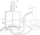
图1是根据本发明实施例提供的云量状态观测系统的主视图;1 is a front view of a cloud cover state observation system provided according to an embodiment of the present invention;
图2是图1沿波浪线截断后的俯视图;Fig. 2 is the top view after Fig. 1 is cut along wavy line;
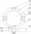
图3是根据本发明实施例提供的防护装置的结构示意图。FIG. 3 is a schematic structural diagram of a protection device provided according to an embodiment of the present invention.
其中的附图标记包括:数据处理终端1、红外波段探测器21、透镜组22、反射集光镜23、镜座24、镜体固定块25、架体固定块26、可见光波段成像模块3、支撑架4、伸缩式调平机构5、第一水平仪601、第一水平仪602、防护装置7、防护盖体71、电机72、旋转轴73、连接块74、关盖限位开关75、开盖限位开关76、挡片77、电机保护壳体78、限位开关保护壳体79、气象监测模块8、抽拉式电箱9、把手91、螺钉92。The reference numerals include: data processing terminal 1,
具体实施方式Detailed ways
在下文中,将参考附图描述本发明的实施例。在下面的描述中,相同的模块使用相同的附图标记表示。在相同的附图标记的情况下,它们的名称和功能也相同。因此,将不重复其详细描述。Hereinafter, embodiments of the present invention will be described with reference to the accompanying drawings. In the following description, the same modules are denoted by the same reference numerals. In the case of the same reference numerals, their names and functions are also the same. Therefore, its detailed description will not be repeated.
为了使本发明的目的、技术方案及优点更加清楚明白,以下结合附图及具体实施例,对本发明进行进一步详细说明。应当理解,此处所描述的具体实施例仅用以解释本发明,而不构成对本发明的限制。In order to make the objectives, technical solutions and advantages of the present invention clearer, the present invention will be further described in detail below with reference to the accompanying drawings and specific embodiments. It should be understood that the specific embodiments described herein are only used to explain the present invention, but not to limit the present invention.
图1和图2分别示出了根据本发明实施例提供的云量状态观测系统的整体结构和局部俯视结构。FIG. 1 and FIG. 2 respectively show the overall structure and the partial top-view structure of the cloud cover state observation system provided according to the embodiment of the present invention.
如图1和图2所示,本发明实施例提供的云量状态观测系统包括数据处理终端1、云量仪和防护装置7,云量仪用于采集红外波段云量图,防护装置7用于对云量仪的局部结构进行防护。As shown in FIG. 1 and FIG. 2 , the cloud cover state observation system provided by the embodiment of the present invention includes a data processing terminal 1, a cloud cover meter, and a
云量仪包括红外波段成像模块、支撑架4和图像传输模块,红外波段成像模块包括红外波段探测器21、透镜组22、反射集光镜23和镜座24,在镜座24的内圈设置有镜体固定块25,在镜座24的外圈设置有架体固定块26,反射集光镜23通过镜体固定块25固定在镜座24上,透镜组22与外波段探测器21红依次置于反射集光镜23的反射方向上,在红外波段探测器21的外部罩有探测器防护罩,支撑架4作为红外波段成像模块的支撑结构通过架体固定块26固定在镜座24上,支撑架4的一端与架体固定块26固定连接,另一端与探测器防护罩固定连接。The cloud meter includes an infrared waveband imaging module, a support frame 4 and an image transmission module. The infrared waveband imaging module includes an
支撑架4由多根支撑杆组成,使云量状态观测系统在采集云量图像时更加牢固稳定。若支撑杆的数量过少,会导致红外波段成像模块的支撑不够稳定,若支撑杆的数量过多,则会遮挡探测范围,因此将支撑杆设置为3根,在确保牢固稳定的同时减少对探测范围的遮挡。架体固定块26的数量与支撑杆的数量相同。The support frame 4 is composed of a plurality of support rods, which makes the cloud cover state observation system more firm and stable when collecting cloud cover images. If the number of support rods is too small, the support of the infrared band imaging module will not be stable enough. If the number of support rods is too large, the detection range will be blocked. Therefore, the number of support rods is set to 3 to ensure firmness and stability while reducing the need for Occlusion of the detection range. The number of the frame body fixing blocks 26 is the same as that of the support rods.
红外波段成像模块的工作原理为:红外光经反射集光镜23反射进入透镜组22,经透镜组22汇聚于红外波段探测器21的靶面,成像为红外波段云量图。The working principle of the infrared band imaging module is as follows: the infrared light is reflected by the
本发明将红外波段探测器与反射集光镜相结合,用以进行云层状态的观测。红外波段探测器受天光背景的影响小,能够实现全天时的云量监测。将红外波段探测器与反射集光镜配合使用可以扩大云量状态观测系统的视场角,从而使云量状态观测系统感测到更大的视野。The invention combines the infrared band detector with the reflection light collecting mirror to observe the cloud state. The infrared band detector is less affected by the sky light background, and can monitor the cloud cover throughout the day. Using the infrared band detector with the reflective concentrator can expand the field of view of the cloud cover state observation system, so that the cloud cover state observation system can sense a larger field of view.
作为一种优选地实施方式,云量仪还包括可见光波段成像模块3,可见光波段成像模块3用于采集可见光波段云量图,并通过图像传输模块将可见光波段云量图与红外波段云量图传输至数据处理终端1,数据处理终端1通过图像融合技术将两个探测器的成像信息融合到一幅图像中,使最终的图像拥有两种不同波段图像的内容,从而展示更多的云层信息细节,有利于后期的云层处理和定位等操作。As a preferred embodiment, the cloud cover further includes a visible light
对于添加可见光波段成像模块3的情况,将探测器防护罩的正上方作为扩展平台,可见光波段成像模块3安装在该扩展平台上。可见光波段成像模块3包括可见光相机,可见光相机配有广角镜头,广角镜头朝向天空,广角镜头可以为普通广角镜头或超广角镜头,本发明实施例优选采用一种特殊的超广角镜头即鱼眼镜头,使镜头达到最大视角。For the case of adding the visible light
将可见光波段成像模块3和红外波段成像模块上下布置而不是水平布置,目的是为了便于图像配准,降低可见光波段云量图与红外波段云量图的融合难度。The purpose of arranging the visible light
本发明实施例提供的云量状态观测系统还包括伸缩式调平机构5,伸缩式调平机构5固定在镜座24的下表面,伸缩式调平机构5通过调节自身的高度来调整云量仪的水平度。The cloud cover state observation system provided by the embodiment of the present invention further includes a
例如伸缩式调平机构5包括三段式套筒,第一段套筒的下端一体成型有底座,第一段套筒的上端与第二段套筒的下端螺纹连接,第二段套筒的上端与第三段套筒的下端螺纹连接,第三段套筒的上端与镜座24的下表面螺纹连接。For example, the
第二段套筒的上端与下端所加工的螺纹的螺距不同,通过不同螺距的螺纹实现对伸缩式调平机构5的粗调与精调。The thread pitches of the threads machined on the upper end and the lower end of the second section of the sleeve are different, and the coarse adjustment and fine adjustment of the
底座与第一段套筒还可以为分体结构,第一段套筒的下端通过螺钉与底座固定连接。The base and the first section of the sleeve can also be of separate structures, and the lower end of the first section of the sleeve is fixedly connected to the base through screws.
又如伸缩式调平机构5包括两根中空支撑柱和底座,在两根中空支撑柱上分别开设有等间距排列的调节孔,两根中空支撑柱套装在一起,向调节孔内拧入调节螺钉将两根中空支撑柱锁紧固定,其中的一根中空支撑柱与镜座24的下表面固定连接,另一根中空支撑柱的底端与底座螺纹连接。Another example is that the
通过调节螺钉与不同调节孔的配合,实现对伸缩式调平机构5的粗调,通过旋转与底座连接的中空支撑柱,实现对伸缩式调平机构5的精调。The coarse adjustment of the
为了检测伸缩式调平机构5是否将云量仪调至水平,在镜座24的上表面还固定有相互垂直摆放的第一水平仪601和第一水平仪602,通过观察第一水平仪601和第一水平仪602中气泡的位置检测云量仪的水平状态。In order to detect whether the
本发明实施例中的云量状态观测系统为便携式系统,系统不需要安装,在使用时直接将系统放置在室外,根据系统携带的两个相互垂直设置的水平仪来调整伸缩式调平机构5的高度,将云量仪调至水平。云量仪不需要使用外部设备额外调平,经过水平调平后,可见光波段探测器、红外波段探测器的像面与当前地点的水平面基本平行,使得两个探测器的观测视角与东北天坐标系相对准,避免因部分区域成像内容为地面,而影响云量仪的观测俯仰角。The cloud cover state observation system in the embodiment of the present invention is a portable system, and the system does not need to be installed. When in use, the system is directly placed outdoors, and the
将可见光波段成像模块固定在红外波段成像模块的上方,可见光波段成像模块的成像中心与红外波段成像模块的成像中心基本一致,两个探测器的像面基本平行。在进行图像融合时,便于确定配准点,能够减少图像坐标变换的复杂度,减少预处理的难度,节省数据处理的时间。The visible light band imaging module is fixed above the infrared band imaging module, the imaging center of the visible light band imaging module is basically the same as the imaging center of the infrared band imaging module, and the image planes of the two detectors are basically parallel. When performing image fusion, it is convenient to determine the registration point, which can reduce the complexity of image coordinate transformation, reduce the difficulty of preprocessing, and save data processing time.
图3示出了根据本发明实施例提供的防护装置的结构。FIG. 3 shows the structure of a protective device provided according to an embodiment of the present invention.
如图3所示,防护装置7包括防护盖体71、电机72、旋转轴73和连接块74,防护盖体71为半球形结构,其与连接块74固定连接,连接块74套装在旋转轴73上通过螺钉固定,旋转轴73的一端通过联轴器与电机72的输出轴固定连接,通过电机72带动旋转轴73转动,使反射集光镜23外部的防护盖体71开启或关闭。As shown in FIG. 3 , the
电机72可以是步进电机、直流无刷电机、直流有刷电机或永磁同步电机。在电机72的外部罩有电机保护壳体78,电机保护壳体78固定在镜座24上,从而实现电机72的安装固定。The
电机72由电机控制器进行控制,电机控制器用于接收数据处理终端1发送的开盖指令和关盖指令,根据开盖指令控制电机72带动防护盖体71进行开盖操作,根据关盖指令控制电机72带动防护盖体71进行关盖操作。The
在旋转轴73的径向两侧分别设置有关盖限位开关75和开盖限位开关76,在旋转轴73上还固定有用于触发关盖限位开关75或开盖限位开关76动作的挡片77。Relevant
关盖限位开关75和开盖限位开关76可以为光电式或机械式,分别与电机控制器进行通信。当挡片77在电机72的带动下触发关盖限位开关75时,关盖限位开关75向电机控制器发出关盖限位信号,电机控制器接收到该关盖限位信号后立即停止电机72转动,此时防护盖体71处于关盖位置;当挡片77在电机72的带动下触发开盖限位开关76时,开盖限位开关76向电机控制器发出开盖限位信号,电机控制器接收到该开盖限位信号后立即停止电机72转动,此时防护盖体71处于开盖位置。The lid-
关盖限位开关75、开盖限位开关76和挡片77构成限位装置,在本发明的一个示例中,限位装置的数量为两套,在一套限位装置失效时,另一套限位装置能够继续工作,保证云量状态观测系统的正常运行。The lid-
只要两个关盖限位开关75中的任意一个发出限位信号,就认为防护盖体71处于关盖位置。同理,只要两个开盖限位开关76中的任意一个发出限位信号,就认为防护盖体71处于开盖位置。As long as any one of the two cover-closing limit switches 75 sends a limit signal, it is considered that the
在本发明的一个具体示例中,在限位装置的外部罩有限位开关保护壳体79,关盖限位开关75和开盖限位开关76分别固定在限位开关保护壳体79内。In a specific example of the present invention, a limit
为了缩小限位开关保护壳体79的体积,减少限位开关保护壳体79所占据的空间,旋转轴73采用阶梯轴,缩小旋转轴73的部分直径,能够节省一部分空间。In order to reduce the volume of the limit switch
电机驱动器可以通过通信接口(CAN、RS422、RS232、RS485、网口)与数据处理终端1进行通信。The motor driver can communicate with the data processing terminal 1 through a communication interface (CAN, RS422, RS232, RS485, network port).
电机控制器与数据处理终端1之间具有通讯故障诊断功能,具体实现方法是:There is a communication fault diagnosis function between the motor controller and the data processing terminal 1, and the specific implementation method is as follows:
(1)、电机控制器与数据处理终端1之间的通讯频率是固定的,例如AHz(A为一个固定值);(1) The communication frequency between the motor controller and the data processing terminal 1 is fixed, such as AHz (A is a fixed value);
(2)、电机控制器内部循环定时1s,当到达定时时间查询接收到的数据处理终端1的数据帧数,如果帧数少于g*A(g为小于1的常数),则认为是通讯故障,电机控制器控制电机72停止转动,同时生成故障码并发送给数据处理终端1。(2) The internal cycle timing of the motor controller is 1s. When the timing time is reached, the number of data frames received by the data processing terminal 1 is queried. If the number of frames is less than g*A (g is a constant less than 1), it is considered as communication If there is a fault, the motor controller controls the
数据处理终端1也采用同样的方式诊断通讯故障。The data processing terminal 1 also diagnoses communication failures in the same manner.
电机控制器还具有开关盖故障诊断功能,能够诊断防护盖体71是否出现开盖功能故障或关盖功能故障。具体实现方法如下:The motor controller also has a switch cover fault diagnosis function, which can diagnose whether the
①、分别测量出防护盖体71正常打开、关闭所需的时间,开盖时间定义为to(to为一个固定值),关盖时间定义为tc(tc为一个固定值);①. Measure the time required for the
②、从电机控制器接收到开盖指令时,开始记录电机72的运行时间,如果运行时间超过k*to(k为大于1且小于1.5的系数,k值过大,在某些故障状态下,可能会导致电机72长时间堵转,致使电机72烧毁),电机控制器仍然未接收到开盖限位信号,电机控制器判定开盖功能异常,若此时电机72在转动,电机控制器会立即控制电机72停止转动,电机控制器会生成故障码并上报给数据处理终端1;②. When receiving the cover opening command from the motor controller, start recording the running time of the
③、从电机控制器接收到关盖指令时,开始记录电机72的运行时间,如果运行时间超过k*tc,电机控制器仍然未接收到关盖限位信号,电机控制器判定关盖功能异常,若此时电机72在转动,电机控制器会立即控制电机72停止转动,电机控制器会生成故障码并上报给数据处理终端1。③. When receiving the lid closing command from the motor controller, start recording the running time of the
与防护装置7相配合,云量状态观测系统还包括气象监测模块8,气象监测模块8与数据处理终端1进行通信,用于实时监测当前的气象数据,并传输至数据处理终端1,数据处理终端1根据当前的天气状况向电机控制器发出开盖指令或关盖指令。In cooperation with the
气象监测模块8可以采用监测是否下雪的雪量传感器或采用监测是否下雨的雨量传感器,气象监测模块8还可以采用将两者功能相集成的雨雪传感器,雨雪传感器既能监测是否下雨又能监测是否下雪。The
当气象监测模块8监测到下雪或下雨信息时,将信息发送至数据处理终端1,通过数据处理终端1判断是否需要关闭防护盖体71,如果需要关闭防护盖体71,则下发关盖指令至电机控制器,电机控制器控制电机72带动反射集光镜23外部的防护盖体71关闭,从而保证反射集光镜23的镀层不受外界恶劣天气的侵蚀,通过气象监测模块8的监测能够实现对对反射集光镜23的自动保护。When the
数据处理终端1采用上位机电脑、嵌入式系统或IOT设备。在数据处理终端1内安装有云量仪观测软件。除了能根据天气情况自动关闭或打开防护盖体71之外,用户还可以通过云量仪观测软件中的开关按钮直接给电机控制器下达开盖指令或关盖指令,来控制防护盖体71的开启或关闭动作。The data processing terminal 1 adopts a host computer, an embedded system or an IOT device. The cloud gauge observation software is installed in the data processing terminal 1 . In addition to automatically closing or opening the
图像传输模块与数据处理终端1之间的通信方式可以为有线通信或无线通信,图像传输模块具有CameraLink接口、光纤接口、CAN接口、RS422接口、RS232接口、RS485接口、网口等数据端口与数据处理终端1进行有线通信,CameraLink接口与光纤接口用于传输图像数据,而CAN接口、RS422接口、RS232接口、RS485接口、网口用于传输数据指令。The communication mode between the image transmission module and the data processing terminal 1 can be wired communication or wireless communication. The image transmission module has a CameraLink interface, an optical fiber interface, a CAN interface, an RS422 interface, an RS232 interface, an RS485 interface, a network port and other data ports and data ports. The processing terminal 1 conducts wired communication, the CameraLink interface and the optical fiber interface are used to transmit image data, and the CAN interface, RS422 interface, RS232 interface, RS485 interface, and network port are used to transmit data commands.
图像传输模块与数据处理终端1之间的无线通信方式可以通过WiFi模块、蓝牙模块或移动通信网络模块等无线传输模块实现。The wireless communication mode between the image transmission module and the data processing terminal 1 can be realized by a wireless transmission module such as a WiFi module, a Bluetooth module or a mobile communication network module.
在本发明实施例的另一个示例中,在镜座24的底部固定有滑道,在滑道上滑动连接有抽拉式电箱9,图像传输模块、电机控制器及向各电器元件供电的供电模块安装在抽拉式电箱9内,在抽拉式电箱9上安装有把手91,通过把手91进行抽拉。在抽拉式电箱9的底部与滑道上分别开设有螺纹孔,当螺钉92旋入螺纹孔后,将抽拉式电箱9固定,防止抽拉式电箱9通过滑道向外滑出,当取下螺钉92后,通过把手91将抽拉式电箱9抽出。拉式电箱9便于检修,并为云量状态观测系统的安装与维护提供了便利条件。In another example of the embodiment of the present invention, a slideway is fixed at the bottom of the
在本说明书的描述中,参考术语“一个实施例”、“一些实施例”、“示例”、“具体示例”、或“一些示例”等的描述意指结合该实施例或示例描述的具体特征、结构、材料或者特点包含于本发明的至少一个实施例或示例中。在本说明书中,对上述术语的示意性表述不必须针对的是相同的实施例或示例。而且,描述的具体特征、结构、材料或者特点可以在任一个或多个实施例或示例中以合适的方式结合。此外,在不相互矛盾的情况下,本领域的技术人员可以将本说明书中描述的不同实施例或示例以及不同实施例或示例的特征进行结合和组合。In the description of this specification, description with reference to the terms "one embodiment," "some embodiments," "example," "specific example," or "some examples", etc., mean specific features described in connection with the embodiment or example , structure, material or feature is included in at least one embodiment or example of the present invention. In this specification, schematic representations of the above terms are not necessarily directed to the same embodiment or example. Furthermore, the particular features, structures, materials or characteristics described may be combined in any suitable manner in any one or more embodiments or examples. Furthermore, those skilled in the art may combine and combine the different embodiments or examples described in this specification, as well as the features of the different embodiments or examples, without conflicting each other.
尽管上面已经示出和描述了本发明的实施例,可以理解的是,上述实施例是示例性的,不能理解为对本发明的限制,本领域的普通技术人员在本发明的范围内可以对上述实施例进行变化、修改、替换和变型。Although the embodiments of the present invention have been shown and described above, it should be understood that the above-mentioned embodiments are exemplary and should not be construed as limiting the present invention. Embodiments are subject to variations, modifications, substitutions and variations.
以上本发明的具体实施方式,并不构成对本发明保护范围的限定。任何根据本发明的技术构思所作出的各种其他相应的改变与变形,均应包含在本发明权利要求的保护范围内。The above specific embodiments of the present invention do not constitute a limitation on the protection scope of the present invention. Any other corresponding changes and modifications made according to the technical concept of the present invention shall be included in the protection scope of the claims of the present invention.
Claims (9)
Priority Applications (1)
| Application Number | Priority Date | Filing Date | Title |
|---|---|---|---|
| CN202210240388.7ACN114660061B (en) | 2022-03-10 | 2022-03-10 | Cloud State Observation System |
Applications Claiming Priority (1)
| Application Number | Priority Date | Filing Date | Title |
|---|---|---|---|
| CN202210240388.7ACN114660061B (en) | 2022-03-10 | 2022-03-10 | Cloud State Observation System |
Publications (2)
| Publication Number | Publication Date |
|---|---|
| CN114660061Atrue CN114660061A (en) | 2022-06-24 |
| CN114660061B CN114660061B (en) | 2023-07-07 |
Family
ID=82028842
Family Applications (1)
| Application Number | Title | Priority Date | Filing Date |
|---|---|---|---|
| CN202210240388.7AActiveCN114660061B (en) | 2022-03-10 | 2022-03-10 | Cloud State Observation System |
Country Status (1)
| Country | Link |
|---|---|
| CN (1) | CN114660061B (en) |
Cited By (2)
| Publication number | Priority date | Publication date | Assignee | Title |
|---|---|---|---|---|
| CN116027461A (en)* | 2022-12-23 | 2023-04-28 | 上海航天控制技术研究所 | Center control method and system for full-automatic space target photoelectric observation station |
| CN116047626A (en)* | 2022-11-18 | 2023-05-02 | 中国科学院长春光学精密机械与物理研究所 | A visible light band cloud cover monitoring method and system thereof |
Citations (13)
| Publication number | Priority date | Publication date | Assignee | Title |
|---|---|---|---|---|
| US20080251733A1 (en)* | 2007-03-28 | 2008-10-16 | Qinetiq Limited | Multiple waveband millimetre and sub-millimetre wave detection system |
| CN204177990U (en)* | 2014-08-08 | 2015-02-25 | 华云升达(北京)气象科技有限责任公司 | A kind of all-sky cloud amount automatic observer with lens protection ball cover |
| US20170299686A1 (en)* | 2014-09-26 | 2017-10-19 | Reuniwatt | Detection unit and method for identifying and monitoring clouds in an observed area of the sky |
| WO2018067996A1 (en)* | 2016-10-06 | 2018-04-12 | View, Inc. | Infrared cloud detector systems and methods |
| US20190094415A1 (en)* | 2017-09-28 | 2019-03-28 | Rosemount Aerospace Inc. | Microscopic imager for aircraft cloud condition detection |
| CN209231197U (en)* | 2018-12-27 | 2019-08-09 | 江苏中美环境监测股份有限公司 | Air monitoring car |
| CN110275281A (en)* | 2019-05-30 | 2019-09-24 | 中国科学院长春光学精密机械与物理研究所 | A space-based total reflection far-ultraviolet and visible light dual-band coronal imaging system |
| CN111526772A (en)* | 2017-12-28 | 2020-08-11 | 爱惜康有限责任公司 | Characterization of tissue irregularities by using monochromatic light refractive index |
| CN111707665A (en)* | 2020-06-16 | 2020-09-25 | 安徽云能天智能科技有限责任公司 | A ground-based dual-band cloud cover automatic observation system and method |
| CN112578555A (en)* | 2020-12-29 | 2021-03-30 | 中国科学院长春光学精密机械与物理研究所 | Common-caliber multi-channel wide-spectrum-band large-view-field imaging optical system |
| CN214413813U (en)* | 2021-01-20 | 2021-10-19 | 三峡大学 | A fish behavior test and observation device |
| US20210381891A1 (en)* | 2020-06-03 | 2021-12-09 | Labsphere, Inc. | Field spectral radiometers including calibration assemblies |
| CN215340335U (en)* | 2021-07-08 | 2021-12-28 | 北方民族大学 | A dual-field multi-wavelength Raman lidar spectroscopic system adapting to different cloud base heights |
- 2022
- 2022-03-10CNCN202210240388.7Apatent/CN114660061B/enactiveActive
Patent Citations (13)
| Publication number | Priority date | Publication date | Assignee | Title |
|---|---|---|---|---|
| US20080251733A1 (en)* | 2007-03-28 | 2008-10-16 | Qinetiq Limited | Multiple waveband millimetre and sub-millimetre wave detection system |
| CN204177990U (en)* | 2014-08-08 | 2015-02-25 | 华云升达(北京)气象科技有限责任公司 | A kind of all-sky cloud amount automatic observer with lens protection ball cover |
| US20170299686A1 (en)* | 2014-09-26 | 2017-10-19 | Reuniwatt | Detection unit and method for identifying and monitoring clouds in an observed area of the sky |
| WO2018067996A1 (en)* | 2016-10-06 | 2018-04-12 | View, Inc. | Infrared cloud detector systems and methods |
| US20190094415A1 (en)* | 2017-09-28 | 2019-03-28 | Rosemount Aerospace Inc. | Microscopic imager for aircraft cloud condition detection |
| CN111526772A (en)* | 2017-12-28 | 2020-08-11 | 爱惜康有限责任公司 | Characterization of tissue irregularities by using monochromatic light refractive index |
| CN209231197U (en)* | 2018-12-27 | 2019-08-09 | 江苏中美环境监测股份有限公司 | Air monitoring car |
| CN110275281A (en)* | 2019-05-30 | 2019-09-24 | 中国科学院长春光学精密机械与物理研究所 | A space-based total reflection far-ultraviolet and visible light dual-band coronal imaging system |
| US20210381891A1 (en)* | 2020-06-03 | 2021-12-09 | Labsphere, Inc. | Field spectral radiometers including calibration assemblies |
| CN111707665A (en)* | 2020-06-16 | 2020-09-25 | 安徽云能天智能科技有限责任公司 | A ground-based dual-band cloud cover automatic observation system and method |
| CN112578555A (en)* | 2020-12-29 | 2021-03-30 | 中国科学院长春光学精密机械与物理研究所 | Common-caliber multi-channel wide-spectrum-band large-view-field imaging optical system |
| CN214413813U (en)* | 2021-01-20 | 2021-10-19 | 三峡大学 | A fish behavior test and observation device |
| CN215340335U (en)* | 2021-07-08 | 2021-12-28 | 北方民族大学 | A dual-field multi-wavelength Raman lidar spectroscopic system adapting to different cloud base heights |
Non-Patent Citations (3)
| Title |
|---|
| BARBARA T. SWEET等: "Image processing and fusion for landing guidance", PROCEEDINGS OF SPIE, pages 84 - 95* |
| 王昊京等: "大视场云层分布定位的光电测量系统", 光学精密工程, vol. 18, no. 8, pages 1722 - 1731* |
| 颜文;龚飞;周颖;周峰;金炜;符冉迪;: "基于NSST与自适应PCNN相结合的卫星云图融合", 光电工程, no. 10, pages 70 - 83* |
Cited By (2)
| Publication number | Priority date | Publication date | Assignee | Title |
|---|---|---|---|---|
| CN116047626A (en)* | 2022-11-18 | 2023-05-02 | 中国科学院长春光学精密机械与物理研究所 | A visible light band cloud cover monitoring method and system thereof |
| CN116027461A (en)* | 2022-12-23 | 2023-04-28 | 上海航天控制技术研究所 | Center control method and system for full-automatic space target photoelectric observation station |
Also Published As
| Publication number | Publication date |
|---|---|
| CN114660061B (en) | 2023-07-07 |
Similar Documents
| Publication | Publication Date | Title |
|---|---|---|
| CN114660061A (en) | Cloud cover state observation system | |
| CN102186008B (en) | All-in-view lightning event observation system and method | |
| CN203037878U (en) | Visibility weather phenomenon monitor with multi-directional panoramic shooting function | |
| CN102520463B (en) | All-sky visible light cloud imaging system | |
| CN202977444U (en) | Support used for solar tracking | |
| CN208476298U (en) | A kind of wisdom garden multi-parameter environmental monitoring integral system | |
| WO2018103167A1 (en) | Sensor and control method thereof | |
| CN112326039A (en) | Photovoltaic power plant patrols and examines auxiliary system | |
| CN202696798U (en) | Intelligent remote measuring device for dual-channel ultrahigh-definition power transmission line | |
| CN102854138A (en) | Visibility measuring system and method based on digital camera shooting method | |
| CN106872030B (en) | Visible-short-wave infrared ultraphotic spectrum irradiance instrument available for long-term automatic Observation | |
| CN114274152A (en) | All-round robot of patrolling and examining | |
| CN107765621A (en) | The automatic inspection method and automatic inspection tour system of a kind of substation equipment | |
| CN103676968A (en) | A sun tracking apparatus | |
| CN102052965A (en) | Remote control vehicle-mounted platform-based method for detecting residential district luminous environment at night | |
| CN113566810B (en) | Time sequence sky polarization mode information acquisition equipment, acquisition system and acquisition method | |
| CN202002978U (en) | Automatic shooting equipment for full view lightning channel images | |
| CN207999098U (en) | A kind of building back side lighting system | |
| CN116576346A (en) | Navigation alarm device for forest fire prevention | |
| CN214959894U (en) | High-order camera and parking management system | |
| CN109115726A (en) | Automatic multi-angle earth's surface optical radiation character viewer | |
| CN203164775U (en) | Beacon indicator | |
| CN211181053U (en) | Laser methane telemetering equipment based on explosion-proof cloud platform | |
| CN208548977U (en) | A kind of photo-electric panorama disaster surveillance device | |
| CN208547419U (en) | A kind of number photoelectronic imaging instrument |
Legal Events
| Date | Code | Title | Description |
|---|---|---|---|
| PB01 | Publication | ||
| PB01 | Publication | ||
| SE01 | Entry into force of request for substantive examination | ||
| SE01 | Entry into force of request for substantive examination | ||
| GR01 | Patent grant | ||
| GR01 | Patent grant |