CN114650929A - seat assembly - Google Patents
seat assemblyDownload PDFInfo
- Publication number
- CN114650929A CN114650929ACN202080062876.2ACN202080062876ACN114650929ACN 114650929 ACN114650929 ACN 114650929ACN 202080062876 ACN202080062876 ACN 202080062876ACN 114650929 ACN114650929 ACN 114650929A
- Authority
- CN
- China
- Prior art keywords
- seat
- adjustment
- unit
- force
- drive unit
- Prior art date
- Legal status (The legal status is an assumption and is not a legal conclusion. Google has not performed a legal analysis and makes no representation as to the accuracy of the status listed.)
- Granted
Links
- 230000007246mechanismEffects0.000claimsabstractdescription69
- 230000004913activationEffects0.000claimsdescription13
- 230000003213activating effectEffects0.000claimsdescription7
- 230000011664signalingEffects0.000description8
- 230000005540biological transmissionEffects0.000description7
- 230000005484gravityEffects0.000description7
- 230000001133accelerationEffects0.000description5
- 238000010586diagramMethods0.000description4
- 230000001681protective effectEffects0.000description4
- 230000001419dependent effectEffects0.000description3
- 238000005259measurementMethods0.000description3
- 229910000831SteelInorganic materials0.000description2
- 108010074506Transfer FactorProteins0.000description2
- 230000008859changeEffects0.000description2
- 230000008878couplingEffects0.000description2
- 238000010168coupling processMethods0.000description2
- 238000005859coupling reactionMethods0.000description2
- 230000007613environmental effectEffects0.000description2
- 239000006260foamSubstances0.000description2
- 230000007935neutral effectEffects0.000description2
- 238000007142ring opening reactionMethods0.000description2
- 239000010959steelSubstances0.000description2
- 229920002430Fibre-reinforced plasticPolymers0.000description1
- 230000005355Hall effectEffects0.000description1
- 239000002131composite materialSubstances0.000description1
- 230000006835compressionEffects0.000description1
- 238000007906compressionMethods0.000description1
- 238000010276constructionMethods0.000description1
- 239000004744fabricSubstances0.000description1
- 239000011151fibre-reinforced plasticSubstances0.000description1
- 238000000034methodMethods0.000description1
- 230000036316preloadEffects0.000description1
- 230000001012protectorEffects0.000description1
- 230000002123temporal effectEffects0.000description1
Images


Classifications
- B—PERFORMING OPERATIONS; TRANSPORTING
- B60—VEHICLES IN GENERAL
- B60N—SEATS SPECIALLY ADAPTED FOR VEHICLES; VEHICLE PASSENGER ACCOMMODATION NOT OTHERWISE PROVIDED FOR
- B60N2/00—Seats specially adapted for vehicles; Arrangement or mounting of seats in vehicles
- B60N2/02—Seats specially adapted for vehicles; Arrangement or mounting of seats in vehicles the seat or part thereof being movable, e.g. adjustable
- B60N2/0224—Non-manual adjustments, e.g. with electrical operation
- B60N2/02246—Electric motors therefor
- B60N2/02253—Electric motors therefor characterised by the transmission between the electric motor and the seat or seat parts
- B—PERFORMING OPERATIONS; TRANSPORTING
- B60—VEHICLES IN GENERAL
- B60N—SEATS SPECIALLY ADAPTED FOR VEHICLES; VEHICLE PASSENGER ACCOMMODATION NOT OTHERWISE PROVIDED FOR
- B60N2/00—Seats specially adapted for vehicles; Arrangement or mounting of seats in vehicles
- B60N2/02—Seats specially adapted for vehicles; Arrangement or mounting of seats in vehicles the seat or part thereof being movable, e.g. adjustable
- B60N2/0224—Non-manual adjustments, e.g. with electrical operation
- B60N2/0244—Non-manual adjustments, e.g. with electrical operation with logic circuits
- B60N2/0268—Non-manual adjustments, e.g. with electrical operation with logic circuits using sensors or detectors for adapting the seat or seat part, e.g. to the position of an occupant
- B—PERFORMING OPERATIONS; TRANSPORTING
- B60—VEHICLES IN GENERAL
- B60N—SEATS SPECIALLY ADAPTED FOR VEHICLES; VEHICLE PASSENGER ACCOMMODATION NOT OTHERWISE PROVIDED FOR
- B60N2/00—Seats specially adapted for vehicles; Arrangement or mounting of seats in vehicles
- B60N2/02—Seats specially adapted for vehicles; Arrangement or mounting of seats in vehicles the seat or part thereof being movable, e.g. adjustable
- B60N2/04—Seats specially adapted for vehicles; Arrangement or mounting of seats in vehicles the seat or part thereof being movable, e.g. adjustable the whole seat being movable
- B60N2/06—Seats specially adapted for vehicles; Arrangement or mounting of seats in vehicles the seat or part thereof being movable, e.g. adjustable the whole seat being movable slidable
- B60N2/08—Seats specially adapted for vehicles; Arrangement or mounting of seats in vehicles the seat or part thereof being movable, e.g. adjustable the whole seat being movable slidable characterised by the locking device
- B60N2/0881—Activation of the latches by the control mechanism
- B—PERFORMING OPERATIONS; TRANSPORTING
- B60—VEHICLES IN GENERAL
- B60N—SEATS SPECIALLY ADAPTED FOR VEHICLES; VEHICLE PASSENGER ACCOMMODATION NOT OTHERWISE PROVIDED FOR
- B60N2/00—Seats specially adapted for vehicles; Arrangement or mounting of seats in vehicles
- B60N2/02—Seats specially adapted for vehicles; Arrangement or mounting of seats in vehicles the seat or part thereof being movable, e.g. adjustable
- B60N2/04—Seats specially adapted for vehicles; Arrangement or mounting of seats in vehicles the seat or part thereof being movable, e.g. adjustable the whole seat being movable
- B60N2/10—Seats specially adapted for vehicles; Arrangement or mounting of seats in vehicles the seat or part thereof being movable, e.g. adjustable the whole seat being movable tiltable
- B—PERFORMING OPERATIONS; TRANSPORTING
- B60—VEHICLES IN GENERAL
- B60N—SEATS SPECIALLY ADAPTED FOR VEHICLES; VEHICLE PASSENGER ACCOMMODATION NOT OTHERWISE PROVIDED FOR
- B60N2/00—Seats specially adapted for vehicles; Arrangement or mounting of seats in vehicles
- B60N2/02—Seats specially adapted for vehicles; Arrangement or mounting of seats in vehicles the seat or part thereof being movable, e.g. adjustable
- B60N2/04—Seats specially adapted for vehicles; Arrangement or mounting of seats in vehicles the seat or part thereof being movable, e.g. adjustable the whole seat being movable
- B60N2/14—Seats specially adapted for vehicles; Arrangement or mounting of seats in vehicles the seat or part thereof being movable, e.g. adjustable the whole seat being movable rotatable, e.g. to permit easy access
- B—PERFORMING OPERATIONS; TRANSPORTING
- B60—VEHICLES IN GENERAL
- B60N—SEATS SPECIALLY ADAPTED FOR VEHICLES; VEHICLE PASSENGER ACCOMMODATION NOT OTHERWISE PROVIDED FOR
- B60N2/00—Seats specially adapted for vehicles; Arrangement or mounting of seats in vehicles
- B60N2/24—Seats specially adapted for vehicles; Arrangement or mounting of seats in vehicles for particular purposes or particular vehicles
- B60N2/42—Seats specially adapted for vehicles; Arrangement or mounting of seats in vehicles for particular purposes or particular vehicles the seat constructed to protect the occupant from the effect of abnormal g-forces, e.g. crash or safety seats
- B60N2/43—Safety locks
- B—PERFORMING OPERATIONS; TRANSPORTING
- B60—VEHICLES IN GENERAL
- B60N—SEATS SPECIALLY ADAPTED FOR VEHICLES; VEHICLE PASSENGER ACCOMMODATION NOT OTHERWISE PROVIDED FOR
- B60N2210/00—Sensor types, e.g. for passenger detection systems or for controlling seats
- B60N2210/40—Force or pressure sensors
Landscapes
- Engineering & Computer Science (AREA)
- Aviation & Aerospace Engineering (AREA)
- Transportation (AREA)
- Mechanical Engineering (AREA)
- Seats For Vehicles (AREA)
Abstract
Translated fromChinese
Description
Translated fromChinese技术领域technical field
本发明涉及一种用于车辆的座椅组件,其具有座椅,尤其是浮动座椅;尤其是具有可相对于本体地板进行调节的车辆座椅,特别时可长度调节、可倾斜、可旋转和/或可枢转。The present invention relates to a seat assembly for a vehicle having a seat, in particular a floating seat; in particular having a vehicle seat adjustable relative to the body floor, in particular length adjustable, reclining, rotatable and/or pivotable.
背景技术Background technique
可调节座椅,特别是诸如浮动座椅的车辆座椅,在现有技术中已知用于最大化舒适度。通常,这种座椅组件的座椅包括用于锁定或解锁浮动座椅的锁定机构以及调节机构。Adjustable seats, particularly vehicle seats such as floating seats, are known in the art to maximize comfort. Typically, the seat of such a seat assembly includes a locking mechanism and an adjustment mechanism for locking or unlocking the floating seat.
发明内容SUMMARY OF THE INVENTION
本发明的目的是提供一种具有座椅、特别是浮动座椅的座椅组件,其具有改进的舒适度和更好的安全性。It is an object of the present invention to provide a seat assembly with a seat, in particular a floating seat, with improved comfort and better safety.
根据本发明,该目的通过具有权利要求1的特征的座椅组件来实现。According to the invention, this object is achieved by a seat assembly having the features of
本发明的改进是从属权利要求的主题。Improvements of the invention are the subject of the dependent claims.
根据本发明的座椅组件包括至少一个座椅,其具有座椅表面区域和靠背区域;基座元件,座椅可调节地设置在该基座元件上;至少一个调节单元,其用于相对于基座元件和/或座椅基座调节座椅;以及至少一个驱动单元,其被构造为以自锁方式锁定基座元件和座椅,并且其中,该锁定可以通过由就坐于座椅中的乘员经由座椅引入调节单元的力也可以通过由驱动单元引入调节单元的力来释放。The seat assembly according to the invention comprises at least one seat having a seat surface area and a backrest area; a base element on which the seat is adjustably arranged; at least one adjustment unit for relative to a base element and/or a seat base to adjust the seat; and at least one drive unit configured to lock the base element and the seat in a self-locking manner, and wherein the locking can be performed by means of a seat seated in the seat The force introduced into the adjustment unit by the occupant via the seat can also be released by the force introduced into the adjustment unit by the drive unit.
本发明以简单的方式允许通过切换就坐于座椅中的人员的重心的自主调节和基于设定或激活的调节模式的机动调节进行组合。The invention allows in a simple manner to combine autonomous adjustment by switching the center of gravity of the person sitting in the seat and motorized adjustment based on a set or activated adjustment mode.
该座椅例如包括相对于彼此固定设置的座椅表面和靠背。座椅调节通过就坐在座椅中的乘员的身体移动实现。与先前已知的座椅调节装置相反,围绕一个或多个调节轴线的调节不是通过手动控制输入设备而是仅通过抵靠座椅,特别是抵靠座椅的座椅表面的乘员的重心或支撑中心的切换来实现。The seat includes, for example, a seat surface and a backrest which are fixedly arranged relative to each other. Seat adjustment is accomplished by the physical movement of the occupant seated in the seat. Contrary to previously known seat adjustment devices, the adjustment about one or more axes of adjustment is not by manual control of the input device but only by the center of gravity of the occupant against the seat, in particular against the seat surface of the seat, or The switch of the support center is realized.
在可能的实施例中,座椅被构造为座椅壳体。代替壳体形式,座椅可以由座椅部分和靠背形成。这些可以是连接在一起的单独座椅部件。可替代地,座椅可以一体形成。In a possible embodiment, the seat is constructed as a seat shell. Instead of a shell form, the seat may be formed by a seat part and a backrest. These can be individual seat parts connected together. Alternatively, the seat may be integrally formed.
本发明还允许即使没有乘客也可以调节座椅。例如,可以自动将座椅带回到“正常”起始位置或更容易进入/退出的位置。这种调节不仅可以在座椅为“空闲”时进行,而且还可以在乘员就坐在座椅中时进行。例如,存储位置,例如座椅位置或轻微或显著倾斜位置,可以自动恢复。The present invention also allows the seat to be adjusted even without a passenger. For example, the seat can be automatically brought back to the "normal" starting position or to an easier entry/exit position. This adjustment can be made not only when the seat is "idle", but also when the occupant is seated in the seat. For example, stored positions, such as seat positions or slightly or significantly reclined positions, can be automatically restored.
换言之,座椅包括利用自锁原理的机械机动调节装置,使得可以省略单独的锁定装置。In other words, the seat comprises a mechanical motorized adjustment device utilizing the self-locking principle, making it possible to omit a separate locking device.
另一实施例提供了:至少一个力传感器设置在座椅和基座元件之间的力流中。力传感器被设置和构造成使得其测量作用在调节单元上的力。力传感器在此联接到驱动单元,使得当调节模式被激活并且力在座椅中的乘员移动之后施加到调节单元时驱动单元的自锁被释放或至少减少。例如,对此,乘员已激活座椅的调节模式,使得由于位于座椅壳体中的乘员的重心或对应支撑的切换,座椅相应地自动移动。Another embodiment provides that at least one force sensor is arranged in the force flow between the seat and the base element. The force sensor is arranged and constructed such that it measures the force acting on the adjustment unit. The force sensor is here coupled to the drive unit such that the self-locking of the drive unit is released or at least reduced when the adjustment mode is activated and a force is applied to the adjustment unit after the movement of the occupant in the seat. For example, for this, the occupant has activated an adjustment mode of the seat, so that due to the switching of the occupant's center of gravity or the corresponding support located in the seat shell, the seat moves automatically accordingly.
另一方面提供了一种联接至驱动单元、力传感器和/或激活单元的控制单元。在此,控制单元联接至力传感器、驱动单元和/或激活单元,以便激活调节模式以用于信号发送和/或控制目的。Another aspect provides a control unit coupled to a drive unit, a force sensor and/or an activation unit. Here, the control unit is coupled to the force sensor, the drive unit and/or the activation unit in order to activate the regulation mode for signaling and/or control purposes.
另一实施例提供了:经由输入单元,例如开关或语音信号,和/或经由激活单元确定乘员的调节命令。通过经由输入单元(例如经由语音命令或通过致动开关)输入调节请求或调节模式,尤其可以激活多种调节模式中的一种。可替代地或附加地,座椅可以包括多个接触传感器(例如也用于检测座椅占用的传感器)作为激活单元,以便激活调节模式。可替代地或附加地,也可以用更少的传感器来确定调节命令,这些更少的传感器检测在驱动单元的靠近驱动装置的致动方向上的力分量。Another embodiment provides that the adjustment command of the occupant is determined via an input unit, eg a switch or a voice signal, and/or via an activation unit. By inputting an adjustment request or an adjustment mode via an input unit, eg via a voice command or by actuating a switch, in particular one of the various adjustment modes can be activated. Alternatively or additionally, the seat may comprise a plurality of contact sensors (eg sensors also for detecting seat occupancy) as activation units in order to activate the adjustment mode. Alternatively or additionally, the adjustment command can also be determined with fewer sensors which detect the force component in the actuation direction of the drive unit close to the drive.
在可能的实施例中,激活浮动模式,其中控制单元被构造为在激活的浮动模式中移动座椅,使得座椅跟随就坐在座椅中的乘员的身体移动。座椅,特别是座椅壳体,没有锁定在假定座椅位置中。In a possible embodiment, the floating mode is activated, wherein the control unit is configured to move the seat in the activated floating mode such that the seat follows the body movement of the occupant seated in the seat. The seat, in particular the seat shell, is not locked in the assumed seat position.
可替代地,可以激活调节模式,其中控制单元被构造为在激活的调节模式中移动座椅,使得座椅跟随就坐在座椅中的乘员的身体移动到达期望座椅位置中,并且其中,座椅是锁定在期望座椅位置中。Alternatively, an adjustment mode may be activated, wherein the control unit is configured to move the seat in the activated adjustment mode such that the seat follows the body movement of an occupant seated in the seat into the desired seat position, and wherein the seat is locked in the desired seat position.
在另一可替代实施例中,可以激活驾驶舒适模式,其中控制单元被构造为在激活的驾驶舒适模式中根据车辆的瞬时行驶移动来调节座椅。In another alternative embodiment, a driving comfort mode may be activated, wherein the control unit is configured to adjust the seat in accordance with the instantaneous driving movement of the vehicle in the activated driving comfort mode.
在另一实施例中,调节单元设计成执行座椅相对于基座元件的调节移动。例如,调节单元被设计为执行弧形、圆形和/或线性调节。在另一实施例中,调节单元构造为心轴驱动装置和/或轨道调节器,特别是圆环调节器和/或线性纵向和/或横向调节器。可替代地,调节单元可以被构造为拉索机构或多种不同类型调节单元的组合。例如,拉索机构被构造为具有周向拉索的弧形拉索。In another embodiment, the adjustment unit is designed to perform an adjustment movement of the seat relative to the base element. For example, the adjustment unit is designed to perform arcuate, circular and/or linear adjustments. In another embodiment, the adjustment unit is designed as a spindle drive and/or a rail adjuster, in particular a ring adjuster and/or a linear longitudinal and/or transverse adjuster. Alternatively, the adjustment unit may be constructed as a cable mechanism or a combination of several different types of adjustment units. For example, the cable mechanism is configured as an arcuate cable with a circumferential cable.
另一实施例提供了:驱动单元包括至少一个齿轮马达单元,该齿轮马达单元联接至调节单元、尤其是联接至拉索机构和/或轨道调节器。驱动单元包括并致动例如鲍登缆线机构或心轴,该鲍登缆线机构或心轴致动拉索机构的缆线和/或至少一个调节单元的轨道,该缆线或轨道作用在为了移动目的而联接到座椅的承载部上。Another embodiment provides that the drive unit comprises at least one gear motor unit which is coupled to the adjustment unit, in particular to the cable mechanism and/or the rail adjuster. The drive unit comprises and actuates, for example, a Bowden cable mechanism or a spindle actuating a cable of the cable mechanism and/or a track of at least one adjustment unit, which cable or track acts on the It is coupled to the carrier of the seat for moving purposes.
在可能的实施例中,齿轮马达单元被构造为具有马达的自锁蜗轮。出于移动目的,拉索机构的缆线或轨道联接至齿轮马达单元的自锁蜗轮。例如,线缆由两个偏转辊保持,该两个偏转辊由齿轮马达单元经由鲍登缆线机构的鲍登缆线驱动。此外,线缆联接至附接至座椅的承载部。In a possible embodiment, the gear motor unit is configured as a self-locking worm gear with a motor. For moving purposes, the cable or track of the cable mechanism is coupled to the self-locking worm gear of the gear motor unit. For example, the cable is held by two deflection rollers, which are driven by the gear motor unit via the Bowden cable of the Bowden cable mechanism. In addition, the cable is coupled to the carrier attached to the seat.
如果承载部件基本上遵循座椅壳体的弧形或弧形段或座椅表面的其他形状,并且缆线搁置在弧形段上的座椅侧上,则调节机构可以被设计成非常坚硬,因为对于缆线而言几乎不需要长度调节。座椅特别是通过缆线和蜗轮的自锁而锁定,但如果使用马达,则座椅也可以经由马达进行调节。The adjustment mechanism can be designed to be very stiff if the load bearing member essentially follows the arc or arc segment of the seat shell or other shape of the seat surface and the cable rests on the seat side on the arc segment, Because almost no length adjustment is required for the cable. The seat is locked in particular by the self-locking of the cable and the worm gear, but if a motor is used, the seat can also be adjusted via the motor.
此外,座椅和基座元件和/或座椅基座以及设置其间的力传感器主动联接,使得作为合力,由就坐在座椅中的乘员引入的力作用在力传感器上。特别是为了主要仅测量由乘员引入座椅中的力,调节机构,尤其是调节单元及其部件(例如拉索机构、偏转辊以及承载部),以及驱动单元经由力传感器支撑抵靠基座元件和/或座椅基座,例如车辆地板。Furthermore, the seat and the base element and/or the seat base and the force sensor disposed therebetween are actively coupled so that as a resultant force, the force introduced by the occupant seated in the seat acts on the force sensor. In particular in order to measure mainly only the forces introduced into the seat by the occupant, the adjustment mechanism, especially the adjustment unit and its components (eg cable mechanism, deflection roller and carrier), as well as the drive unit are supported against the base element via force sensors and/or seat bases, such as vehicle floors.
通过将力传感器设置在座椅基座和座椅之间(其中座椅部件(例如调节单元、驱动单元和承载部)安装在结构支撑上),确保了调节单元确保没有游隙所需的预加载,例如拉索机构的缆线所需的预紧力,不叠加在力测量信号上,而只有来自调节命令的合力作用在力传感器上。By arranging the force sensor between the seat base and the seat, where the seat components (eg adjustment unit, drive unit and carrier) are mounted on the structural support, it is ensured that the adjustment unit ensures that there is no pre-play required for the adjustment unit. Loads, such as the preload required for the cables of the cable mechanism, are not superimposed on the force measurement signal, but only the resultant force from the adjustment command acts on the force sensor.
为此,具有至少调节单元和/或驱动单元的基座元件和/或所述基座元件本身通过支撑点安装在座椅基座上,例如车辆地板上。为了确保该单一力传递点,调节单元和/或驱动单元在支撑点处抵靠座椅基座安装,使得在测量方向上的力分量受到尽可能小的影响。For this purpose, the base element with at least the adjustment unit and/or the drive unit and/or the base element itself is mounted via a support point on the seat base, for example on the vehicle floor. In order to ensure this single force transmission point, the adjustment unit and/or the drive unit are mounted against the seat base at the support point so that the force component in the measuring direction is influenced as little as possible.
对于座椅组件的紧凑结构,驱动单元以及调节单元和/或控制单元都可以分配至基座元件。此外,可以提供对调节单元的单独引导,例如对缆线的单独引导。此外,对缆线在偏转辊上方的引导及其经由鲍登缆线的移动允许将驱动单元分配至基座元件,使得座椅壳体承载更少的重量。这也简化了对马达的供电。For the compact construction of the seat assembly, both the drive unit and the adjustment unit and/or the control unit can be assigned to the base element. Furthermore, separate guidance of the adjustment unit, eg of the cables, can be provided. Furthermore, the guidance of the cables over the deflection rollers and their movement via the Bowden cables allows the distribution of the drive unit to the base element so that the seat shell carries less weight. This also simplifies powering the motor.
为了使座椅围绕其竖直轴线旋转,可以提供单独的调节装置。该单独的调节装置包括例如由马达和蜗轮形成的另一驱动单元,该另一驱动单元直接设置在座椅的枢轴点处或沿着座椅的座椅壳体的弧形段以枢轴点作为中心点进行设置而没有拉索机构,或者联接至座椅或座椅壳体,其中另一个力传感器作为用于切向作用力的传递元件设置在座椅或座椅壳体与基座元件之间并测量切向作用力。In order to rotate the seat about its vertical axis, a separate adjustment device can be provided. The separate adjustment device comprises a further drive unit, for example formed by a motor and a worm gear, which is arranged directly at the pivot point of the seat or along an arcuate section of the seat shell of the seat with the pivot point as the pivot point The center point is provided without a cable mechanism, or is coupled to the seat or seat shell, wherein another force sensor is provided as a transmission element for tangential forces between the seat or seat shell and the base element. and measure the tangential force.
此外,力阈值可以参数化。由于可以参数化力阈值、调节机构的时间行为以及力施加和调节速度的转移因子,可以调节和修改座椅的调节行为。特别地,用于位置确定的其他传感器可以允许设置与位置相关的调节参数。Furthermore, the force threshold can be parameterized. Since the force threshold, the temporal behavior of the adjustment mechanism and the transfer factor of the force application and adjustment speed can be parameterized, the adjustment behavior of the seat can be adjusted and modified. In particular, other sensors for position determination may allow setting of position-dependent adjustment parameters.
此外,可以提供多个端部止动件来限制座椅的调节移动。此外,可以提供基于座椅环境传感器的困陷保护装置。此外,可以考虑、尤其是补偿环境影响,例如车辆加速或减速。为此,通过控制单元,可以确定诸如车辆加速度或减速度的车辆参数并且可以相应地产生用于驱动单元的适配控制信号。Additionally, multiple end stops may be provided to limit adjustment movement of the seat. Additionally, entrapment protection based on seat environment sensors may be provided. Furthermore, environmental influences, such as vehicle acceleration or deceleration, can be taken into account, in particular compensated. For this purpose, via the control unit, vehicle parameters such as vehicle acceleration or deceleration can be determined and adapted control signals for the drive unit can be generated accordingly.
座椅壳体还可以设置有用于吸收过载力的过载保护。过载保护可防止必须通过调节单元和自锁驱动单元消散的强力,例如由于事故。这种过载保护例如由两个T形杆形成,其脚部点安装在座椅上并连接在一起。例如,在T形杆的横杆上方附接有缆线,特别是钢缆或心轴。与另一个杆相反的锯齿结构设置在每个杆下方。The seat shell may also be provided with overload protection for absorbing overload forces. Overload protection protects against strong forces that have to be dissipated through the adjustment unit and the self-locking drive unit, eg due to an accident. This overload protection is formed, for example, by two T-bars, the foot points of which are mounted on the seat and connected together. For example, cables, in particular steel cables or mandrels, are attached above the crossbars of the T-bar. A sawtooth structure opposite to the other rod is provided below each rod.
在另一实施例中,座椅设计为具有座椅表面区域和靠背区域的座椅壳体,其中座椅壳体可通过调节机构在至少两个旋转自由度上相对于基座元件进行调节,在尤其是可旋转、可倾斜和/或可枢转,其中调节机构包括至少一个调节单元,其用于在至少一个旋转自由度上调节座椅壳体,并且具有至少一个相关联的驱动单元,其可通过控制单元被控制用于在至少一个旋转自由度上调节座椅壳体,并且其中至少一个力传感器设置在至少一个驱动单元和相应的调节单元之间的力流中并且联接到控制单元用于信号发出和/或控制目的。In a further embodiment, the seat is designed as a seat shell with a seat surface area and a backrest area, wherein the seat shell is adjustable relative to the base element in at least two rotational degrees of freedom by means of an adjustment mechanism, in particular rotatable, tiltable and/or pivotable, wherein the adjustment mechanism comprises at least one adjustment unit for adjusting the seat shell in at least one rotational degree of freedom and with at least one associated drive unit, It is controllable by the control unit for adjusting the seat shell in at least one rotational degree of freedom, and wherein at least one force sensor is arranged in the force flow between the at least one drive unit and the corresponding adjustment unit and is coupled to the control unit For signaling and/or control purposes.
通过本发明实现的优点尤其包括座椅组件的这种座椅可以根据就坐在座椅中的人员的身体移动在控制下进行调节。The advantages achieved by the present invention include, inter alia, that such a seat of the seat assembly can be adjusted under control according to the body movements of the person seated in the seat.
因此,座椅,特别是座椅壳体,可以自动地采取期望位置。通过这种直接力控调节机构,使座椅能够以自由浮动座椅(也称为浮动座椅)的方式进行调节或移动,特别是可以向前或向后或向侧方倾斜并围绕竖直轴线旋转。Thus, the seat, in particular the seat shell, can automatically assume the desired position. This direct force-controlled adjustment mechanism enables the seat to be adjusted or moved in the manner of a free-floating seat (also known as a floating seat), in particular reclining forwards or backwards or sideways and around vertical axis rotation.
为此,力传感器直接位于座椅,特别是调节单元(例如枢转机构或旋转机构或倾斜机构)和基座元件,特别是相关的驱动单元(例如用于枢转机构的驱动单元、用于旋转机构的驱动单元和用于倾斜机构的驱动单元)和/或座椅基座,特别是车辆地板之间的力流中。For this purpose, the force sensors are located directly on the seat, in particular the adjustment unit (eg pivot or swivel or tilt mechanism) and the base element, especially the associated drive unit (eg drive unit for the pivot mechanism, for drive units for swivel mechanisms and drive units for reclining mechanisms) and/or seat bases, especially in the force flow between the vehicle floor.
在此,座椅在相应的力流中沿通过力传感器测量的最大力的方向移动。特别地,座椅在控制下被调节,使得在相应的力流中测量的力越大,则相关联的驱动单元(调节马达)越快地调节座椅。In this case, the seat moves in the direction of the maximum force measured by the force sensor in the corresponding force flow. In particular, the seat is adjusted under control such that the greater the force measured in the corresponding force flow, the faster the associated drive unit (adjustment motor) adjusts the seat.
控制单元还被构造成使得为了调节座椅,可选地或附加地,可以激活各种调节模式。The control unit is also configured such that for adjusting the seat, alternatively or additionally, various adjustment modes can be activated.
例如,控制单元包括浮动模式,该浮动模式被配置为在激活时使得座椅、特别是座椅壳体跟随就坐在座椅中、特别是座椅壳体中的人员的身体移动。为此,控制单元根据一个或多个力传感器的瞬时力信号控制一个或多个驱动单元,并因此根据身体移动-向前或向后或向侧面倾斜,和/或围绕竖直轴线旋转座椅-并与身体同步地连续调节座椅相对于基座元件和/或座椅基座的姿态和/或位置。For example, the control unit includes a floating mode configured to, when activated, cause the seat, in particular the seat shell, to follow the body of a person sitting in the seat, in particular the seat shell. For this purpose, the control unit controls one or more drive units according to the instantaneous force signals of one or more force sensors and thus according to body movement - tilting forwards or backwards or sideways, and/or rotating the seat around a vertical axis - and continuously adjust the posture and/or position of the seat relative to the base element and/or the seat base in synchronization with the body.
此外,控制单元可以包括调节模式,该调节模式被配置为在激活时使得座椅,例如,座椅壳体,跟随就坐在座椅中,例如座椅壳体中的人员的身体移动进入期望座椅位置,其中座椅,特别是座椅壳体,被锁定在该期望座椅位置中。Furthermore, the control unit may include an adjustment mode configured to, when activated, cause the seat, eg the seat shell, to follow the body movement of a person sitting in the seat, eg the seat shell, into the desired seat The seat position, in which the seat, in particular the seat shell, is locked in the desired seat position.
此外,控制单元可以包括驾驶舒适模式(也称为主动浮动模式),其被配置为在激活时使得对座椅,例如座椅壳体的调节根据车辆的瞬时行驶移动,例如制动、转弯或加速而发生。例如,当车辆行驶通过拐角时,座椅,例如座椅壳体相应地向侧面倾斜,特别是相应地倾斜至角落中。此外,根据可能识别的碰撞,可以将座椅设置或保持在对就坐在座椅中,例如座椅壳体中的人员安全的座椅位置中。此外,如在碰撞器件产生的对应强力的情况下,可以主动浮动调节座椅以抵消作用力。为此,控制单元附加地为了信号发出目的而联接至其他传感器、尤其是加速度、制动、速度和/或碰撞传感器和/或车辆中的其他控制单元。Furthermore, the control unit may include a driving comfort mode (also referred to as an active float mode) which, when activated, is configured to cause adjustments to the seat, such as the seat shell, to move according to the vehicle's instantaneous travel, such as braking, cornering or occurs at an accelerated rate. For example, when the vehicle is driving through a corner, the seat, eg the seat shell, is correspondingly tilted sideways, in particular correspondingly into the corner. In addition, depending on a potentially recognized collision, the seat can be set or maintained in a seat position that is safe for persons sitting in the seat, for example in the seat shell. In addition, the seat can be actively float-adjusted to counteract the force, as in the case of the corresponding force generated by the crash device. For this purpose, the control unit is additionally coupled for signaling purposes to other sensors, in particular acceleration, braking, speed and/or crash sensors and/or other control units in the vehicle.
一个方面提供了:座椅可以通过调节机构至少围绕横向轴线相对于基座元件倾斜,特别是向前倾斜(例如-8°)或向后倾斜(例如+15°),并围绕竖直轴线旋转,特别是相对于车辆的纵向轴线旋转,向外旋转45°或向内旋转15°。One aspect provides that the seat can be tilted relative to the base element at least about a transverse axis, in particular forward (eg -8°) or rearward (eg +15°), and rotated about a vertical axis by means of an adjustment mechanism , in particular with respect to the longitudinal axis of the vehicle, by 45° outwards or 15° inwards.
在可能的实施例中,座椅可以相对于基座元件在纵向飞行上围绕横向轴线相对于中性位置在-8°(向前)到+15°(向后)之间的范围内倾斜,该中性位置例如对应于到+25°的座椅或设计位置;和/或在横向方向上围绕纵向轴线在0°和5°之间的范围内倾斜或滚转,和/或围绕浮动座椅的竖直轴线旋转或枢转最大45°,特别是相对于车辆的纵向轴线向外旋转45°或向内旋转15°。In a possible embodiment, the seat can be tilted in longitudinal flight relative to the base element in a range between -8° (forward) and +15° (rearward) about the transverse axis relative to the neutral position, This neutral position corresponds, for example, to a seat or design position to +25°; and/or tilt or roll in the lateral direction around the longitudinal axis in the range between 0° and 5°, and/or around the floating seat The vertical axis of the seat is rotated or pivoted by a maximum of 45°, in particular by 45° outwards or 15° inwards with respect to the longitudinal axis of the vehicle.
例如,在设计或座椅位置中,座椅采用这种姿势:其中,座椅在纵向方向上并且因此在行进/视觉方向上朝向前方定向。该位置称为相对于竖直轴线(Z轴)和纵向轴线(X轴线)的0°位置。在这种设计或座椅位置中,为了提高座椅舒适度,座椅可以围绕横向轴线(Y轴线)向后倾斜,例如+25°。座椅可以通过调节机构相对于设计或座椅位置(例如围绕横向轴线)向前倾斜高达-8°以改善进入或退出或向后倾斜高达15°以用于斜倾座椅位置。座椅最多可围绕横向轴线倾斜120°。相对于设计或座椅位置,座椅壳体可以围绕竖直轴线尤其旋转最大280°,特别是-90°至+190°,特别是向外45°或向内15°。For example, in a design or seating position, the seat assumes a posture in which the seat is oriented forward in the longitudinal direction and thus in the travel/view direction. This position is referred to as the 0° position relative to the vertical axis (Z axis) and the longitudinal axis (X axis). In this design or seating position, the seat can be tilted back about the lateral axis (Y-axis), eg +25°, in order to improve seat comfort. The seat can be reclined up to -8° forward relative to the design or seat position (eg, about a lateral axis) by an adjustment mechanism to improve entry or exit or up to 15° rearward for a reclined seat position. The seat can be tilted up to 120° around the transverse axis. Relative to the design or seat position, the seat shell can be rotated in particular up to 280° about the vertical axis, in particular -90° to +190°, in particular 45° outwards or 15° inwards.
附图说明Description of drawings
下面参照附图说明本发明的示例性实施例。附图示出了:Exemplary embodiments of the present invention are described below with reference to the accompanying drawings. The attached figure shows:
图1示意性地示出了具有可调节座椅、调节机构和控制单元的座椅组件,该控制单元联接到驱动单元以用于调节座椅,Figure 1 schematically shows a seat assembly with an adjustable seat, an adjustment mechanism and a control unit coupled to a drive unit for adjusting the seat,
图2以透视图示意性地示出了具有可调节座椅,特别是浮动座椅的座椅组件,Figure 2 schematically shows a seat assembly with an adjustable seat, in particular a floating seat, in a perspective view,
图3以从上方到可调节座椅的座椅表面的平面图示意性地示出了用于座椅的调节机构,Figure 3 schematically shows the adjustment mechanism for the seat in a plan view from above to the seat surface of the adjustable seat,
图4从下方地平面图示意性地示出了图3中的座椅的调节机构,Figure 4 schematically shows the adjustment mechanism of the seat of Figure 3 from below in plan view,
图5以截面图示意性地示出了图3或图4中的调节机构,Fig. 5 schematically shows the adjustment mechanism of Fig. 3 or Fig. 4 in a sectional view,
图6至8以各种示图示意性地示出了力传感器的区域中的调节机构,Figures 6 to 8 schematically show the adjustment mechanism in the area of the force sensor in various representations,
图9以透视图示意性地示出了具有可自由调节座椅壳体的座椅,Figure 9 schematically shows a seat with a freely adjustable seat shell in a perspective view,
图10至12以透视图示意性地示出了调节机构,Figures 10 to 12 schematically show the adjustment mechanism in a perspective view,
图13是座椅的另一个实施例的示意图,该座椅具有带有自锁驱动单元的可自由调节座椅壳体,Figure 13 is a schematic view of another embodiment of a seat having a freely adjustable seat shell with a self-locking drive unit,
图14示出了过载保护在空载状态下的示意图,Figure 14 shows a schematic diagram of the overload protection in the no-load state,
图15示出了过载保护在负载状态下的示意图,Figure 15 shows a schematic diagram of overload protection under load,
图16示出了具有联接的驱动单元的调节机构的另一个实施例的透视图,以及Figure 16 shows a perspective view of another embodiment of an adjustment mechanism with a coupled drive unit, and
图17示意性地示出了控制单元、力传感器和驱动单元的联接的实施例。Figure 17 schematically shows an embodiment of the coupling of the control unit, the force sensor and the drive unit.
具体实施方式Detailed ways
在所有附图中,相互对应的部分带有相同的附图标记。In all the figures, parts corresponding to each other bear the same reference numerals.
图1示意性地示出了座椅1,特别是车辆座椅。座椅1尤其设置在车辆中并且以未详细示出的方式附接至车辆地板。座椅2被构造为可移动的、特别是可自由浮动调节的座椅2(也称为浮动座椅)。座椅2可以被构造为如下文更详细地说明和描述的座椅壳体。可替代地,座椅2可以利用座椅部分和靠背(未详细示出)以传统方式由多部件形成。以下使用座椅壳体为例对座椅2的调节相应地适用于对多件式座椅的调节。Figure 1 schematically shows a
如下所述,座椅组件1的座椅2可以以各种模式移动。为此,座椅组件1包括基座元件3,座椅2设置在该基座元件3上以便可相对于基座元件3和/或座椅基座9进行调节。为了调节座椅2,座椅组件1包括至少一个调节单元4和驱动单元5。As described below, the
座椅2被构造为具有靠背区域2.1和座椅表面区域2.2的座椅壳体。The
为了使用对座椅壳体的调节为例更清楚地说明座椅调节,以下将座椅壳体称为“座椅壳体2”。In order to illustrate the seat adjustment more clearly using the adjustment of the seat shell as an example, the seat shell is hereinafter referred to as "
座椅壳体2可以通过调节单元4相对于基座元件3在几个旋转自由度R1至R3中的至少两个上进行调节;特别地,其是可旋转的、可倾斜的和/或可枢转的。第一旋转自由度R1允许座椅壳体2围绕横向轴线Y进行调节,第二旋转自由度R2允许座椅壳体2围绕纵向轴线X进行调节,以及第三旋转自由度R3允许围绕竖直轴线Z进行调节。The
调节单元4针对每个旋转自由度R1、R2可以包括至少一个单独调节单元4.1、4.2(在图1和2至6、10至11中示出)以用于调节座椅壳体2。The
相应的调节单元4、4.1、4.2联接到至少一个相关联的驱动单元5、5.1、5.2以用于使座椅壳体2移动,特别是自由浮动移动或调节。为了实现座椅壳体2在至少一个旋转自由度R1、R2中的受控移动,特别是调节,一个或多个相应驱动单元5、5.1、5.2可以通过控制单元6来控制。The
此外,至少一个力传感器7、7.1、7.2设置在至少一个驱动单元5、5.1、5.2与相应调节单元4、4.1、4.2之间的力流F中,并联接至控制单元6以用于信号发出和/或控制目的。Furthermore, at least one
此外,座椅组件1包括激活单元10,其用于激活用于解锁和调节座椅壳体2的调节模式。激活单元10还联接到控制单元6以用于信号发出和/或控制目的。Furthermore, the
具有以这种方式构造的座椅壳体2、具有由力传感器7、7.1、7.2控制的驱动单元5、5.1和5.2和调节单元4、4.1、4.2的座椅组件1允许座椅壳体2的各种移动,特别是舒适和例如自由浮动移动。特别地,具有这种座椅2的座椅组件1可以根据就坐在座椅壳体2中的人员的身体移动在控制下进行调节。因此,座椅2,尤其是座椅壳体2可以自动利用自由移动采用期望位置。通过这种具有一个或多个调节单元4、4.1、4.2的直接力控调节机构,座椅壳体2可以自由浮动的座椅壳体2的方式调节或移动,特别是可以围绕横向轴线Y向前或向后倾斜并围绕纵向轴线X向侧面倾斜,并围绕竖直轴线Z旋转。The
在此,相应的驱动单元5、5.1和/或5.2被构造为以自锁方式锁定基座元件3和座椅壳体2,其中锁定可以通过由就坐在座椅壳体2中的乘员经由座椅壳体2引入调节单元4、4.1和/或4.2的力F(I)并且还通过由驱动单元5、5.1和/或5.2中的一个引入调节单元4、4.1和/或4.2的力F(5)来释放。The
图2以透视图示意性地示出了可移动的、特别是可调节的座椅2。座椅2被构造为浮动座椅或自由浮动或可自由移动座椅壳体2。FIG. 2 schematically shows a movable, in particular
这里,座椅壳体2可以由靠背区域2.1和座椅表面区域2.2形成为单件或多件。可替代地,座椅壳体2可以由单独的靠背区域2.1和可调节地,特别是可倾斜地(未详细示出)设置在单独靠背区域上的座椅表面区域2.2形成。座椅壳体2包括承载部2.3,特别是硬泡沫壳体或复合壳体,特别是由纤维增强塑料制成。此外,座椅壳体2可以设置有设置在其上的衬垫元件(未详细示出),特别是具有或不具有覆盖物的泡沫衬垫。Here, the
单件式座椅壳体2可相对于基座元件3移动。作为调节机构,在座椅壳体2和基座元件3之间设置多个调节单元4至4.2。The one-
特别地,调节机构被构造为执行座椅壳体2相对于基座元件3的组合调节移动。例如,调节单元4、4.1、4.2被构造为执行弓形、圆形和/或线性调节。在另一实施例中,调节单元4、4.1、4.2被构造为心轴驱动装置和/或轨道调节器,特别是圆环调节器和/或线性纵向和/或横向调节器。为此,相应的调节单元4、4.1、4.2可以包括铰链安装件、滑动轴承、轨道安装件或辊子轴承。因此,座椅壳体2安装在基座元件3上以便可移动,特别是可滑动移动,特别是可倾斜、可旋转和/或可枢转。借助调节单元4、4.1、4.2,座椅壳体2可相对于基座元件3在三个旋转自由度R1、R2和/或R3中的至少两个或所有上移动,特别是可倾斜、可旋转和/或可枢转。In particular, the adjustment mechanism is configured to perform a combined adjustment movement of the
例如,在设计或座椅位置P1中,座椅壳体2采用座椅壳体2在纵向方向x上并且因此在行进/视觉方向上朝前定向的姿态。该座椅位置P1被称为相对于竖直轴线Z和纵向轴线X的0°位置。在该座椅位置P1中,座椅壳体2围绕横向轴线Y向后倾斜25°以提高就座舒适度。在此,具有调节单元4、4.1、4.2的调节机构被构造为使得,相对于设计或座椅位置P1,座椅壳体2可以例如为围绕横向轴线Y(旋转自由度R1)相对于25°向前倾斜多达-10°或-8°且向后倾斜多大+15°,和/或围绕竖直轴线Z(旋转度自由度R2)旋转特别是最大280,特别是向外旋转+45°且向内旋转-15°。For example, in the design or seat position P1, the
特别地,对于每个旋转自由度R1、R2,调节机构包括相关联的调节单元4.1和4.2。用于使座椅壳体2围绕横向轴线Y向前或向后倾斜移动并且围绕纵向轴线X向侧面倾斜移动的调节单元4.1被构造例如作为枢轴接头、滑动机构或拉索机构41.1或作为具有辊子轴承的轨道调节机构。对于座椅壳体2围绕竖直轴线Z的旋转移动,调节单元4.2例如构造为具有辊子轴承的环形轨道机构。In particular, for each rotational degree of freedom R1, R2, the adjustment mechanism comprises an associated adjustment unit 4.1 and 4.2. The adjustment unit 4.1 for tilting the
调节单元4.1、4.2为了移动目的彼此联接。此外,调节单元4.1、4.2设置在基座元件3和座椅壳体2之间,特别是在座椅壳体2下方,特别是在座椅表面区域2.2的下侧。The adjustment units 4.1, 4.2 are coupled to each other for movement purposes. Furthermore, the adjustment units 4.1, 4.2 are arranged between the
此外,基座元件3可以设置在长度调节单元8上,特别是轨道对上,以用于座椅1相对于座椅基座9,例如车辆地板的长度调节。基座元件3例如是座椅承载部并且包括多个横杆元件3.1。可替代地,基座元件3也可以被构造为承载部板3.2(例如在图5、9、16中示出)。Furthermore, a
为了紧凑设置,驱动单元5.1、5.2和控制单元6可以分配至基座元件3,并安装在其上并附接到其上。基座元件3又安装在座椅基座9上。For a compact arrangement, the drive units 5.1, 5.2 and the
座椅组件1因此被构造为使得座椅壳体2相对于基座元件3和/或座椅基座9的位置可以例如通过长度调节单元8沿纵向方向x在平移自由度T1、T2上和/或通过调节单元4.1、4.2在旋转自由度R1至R3上进行设置。为此,调节机构设有调节单元4.1、4.2。座椅壳体2在多于两个自由度上的位置的自由移动,特别是设置或调节,产生浮动或滑动座椅壳体2的印象,其跟随座椅壳体2中的人员由于就坐在座椅壳体2中的人员的重心的变换而产生的移动。The
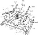
图3以从上方到可移动座椅1的座椅表面区域2.2的部分透明平面图示意性地示出了具有用于座椅壳体2围绕横向轴线Y的向前或向后倾斜移动的调节单元4.1(也称为Y调节单元4.1)以及用于座椅壳体2围绕竖直轴线Z的旋转移动的调节单元4.2(也称为Z调节单元4.2)的调节机构。FIG. 3 schematically shows in a partially transparent plan view from above the seat surface area 2.2 of the
Y调节单元4.1例如构造为滑动机构,尤其是轨道辊机构。Y调节单元4.1包括至少三个轨道4.1.1和相关联的带有辊子的辊子轴承4.1.2,座椅壳体2通过这些辊子轴承相对于基座元件3可滑动地安装。Z调节单元4.2例如构造成作为具有环形轨道的环形轨道调节机构4.2.1。The Y-adjustment unit 4.1 is designed, for example, as a sliding mechanism, in particular a track roller mechanism. The Y-adjustment unit 4.1 comprises at least three rails 4.1.1 and associated roller bearings 4.1.2 with rollers by which the
图4以从下方的平面图示意性地显示了图3中座椅1的调节机构4。FIG. 4 schematically shows the
为了使座椅壳体2围绕横向轴线Y向前或向后倾斜移动,调节单元4.1包括具有辊子4.1.2的彼此分开的至少两个弯曲轨道4.1.1以用于座椅壳体2在轨道4.1.1上的滑动或滚动移动。相应的轨道4.1.1还包括在纵向方向x上沿座椅壳体2的方向突出的端部止动件4.1.3,以用于限制座椅壳体2围绕横向轴线Y的向前和向后倾斜移动。调节单元4.1包括用于固定轨道4.1.1的承载部元件4.1.4,特别是承载部板3.2。In order to tilt the
此外,调节单元4.1可以包括具有辊子4.1.2的引导轨道4.1.5。引导轨道4.1.5和辊子4.1.2确保在Y方向(横向移动)或Z方向(绕竖直轴线Z旋转或转动)上不存在游隙。引导轨道4.1.5可以形成为直的或弯曲的。可替代地,引导轨道4.1.5也可以在功能上实现在长度调节单元8中(未详细示出)。Furthermore, the adjustment unit 4.1 may comprise guide rails 4.1.5 with rollers 4.1.2. Guide rails 4.1.5 and rollers 4.1.2 ensure that there is no play in the Y direction (lateral movement) or Z direction (rotation or rotation about the vertical axis Z). The guide rail 4.1.5 can be formed straight or curved. Alternatively, the guide rail 4.1.5 can also be functionally implemented in the length adjustment unit 8 (not shown in detail).
为了使座椅壳体2围绕竖直轴线Z旋转移动,调节单元4.2包括环形轨道4.2.1,该环形轨道4.2.1设置并固定在承载部元件4.1.4的通道开口4.1.6中。For the rotational movement of the
环形轨道4.2.1构造为水平环形轨道对,包括上环形轨道4.2.2和下环形轨道4.2.3。上环形轨道4.2.2固定地保持在承载部元件4.1.4中。下环形轨道4.2.3固定地保持在基座元件3上。除了横向承载部元件3.1之外,基座元件3还包括用于固定下环形轨道4.2.3的承载部板3.2。The annular track 4.2.1 is configured as a pair of horizontal annular tracks comprising an upper annular track 4.2.2 and a lower annular track 4.2.3. The upper annular rail 4.2.2 is held fixedly in the carrier element 4.1.4. The lower annular rail 4.2.3 is held fixedly on the
图5以截面视图示意性地显示了具有图3或图4的调节单元4.1和4.2的调节机构。FIG. 5 schematically shows an adjustment mechanism with the
承载部板3.2和承载部元件4.1.4各自具有居中通道开口3.2.1或4.1.6,其彼此上下重叠。环形轨道4.2.2、4.2.3相对于承载部板3.2和承载部元件4.1.4设置成使得内环开口4.2.4和下承载部板3.2和上承载部元件4.1.4的通道开口3.2.1、4.1.6分别彼此上下重叠。The carrier plate 3.2 and the carrier element 4.1.4 each have a central channel opening 3.2.1 or 4.1.6, which overlap each other. The annular rails 4.2.2, 4.2.3 are arranged relative to the carrier plate 3.2 and the carrier element 4.1.4 such that the inner ring opening 4.2.4 and the passage opening 3.2 of the lower carrier plate 3.2 and the upper carrier element 4.1.4. 1, 4.1.6 respectively overlap each other up and down.
座椅壳体2的力控移动在下文中使用用于使座椅壳体2围绕横向轴线Y的倾斜移动的调节单元4.1为示例进行描述。The force-controlled movement of the
为此,力传感器7.1位于座椅壳体2和座椅基座9之间的力流F中。用于调节单元4.1的力传感器7.1尤其直接位于调节单元4.1和相关联的驱动单元5.1之间的力流F中。For this purpose, the
力传感器7.1例如构造为用于检测压力和/或张力负载的张力和/或压力传感器。例如,力传感器7.1是应变仪或检测变形、尤其是伸长或压缩的其他合适部件。力传感器7.1连接到控制单元6用于信号发出和控制目的。The force sensor 7.1 is designed, for example, as a tension and/or pressure sensor for detecting pressure and/or tension loads. For example, the force sensor 7.1 is a strain gauge or other suitable component that detects deformation, especially elongation or compression. The force sensor 7.1 is connected to the
在示例性实施例中,驱动单元5.1被构造为鲍登缆线机构5.1.5。驱动单元5.1包括例如马达5.1.1和鲍登缆线5.1.2,以及用于将马达5.1.1的调节力传递成座椅壳体2沿调节单元4.1,特别是轨道4.1.1和引导轨道4.1.5的调节移动的力传递元件5.1.3。为此,鲍登缆线5.1.2在端部处连接到座椅壳体2和马达5.1.1的输出侧。In the exemplary embodiment, the drive unit 5.1 is configured as a Bowden cable mechanism 5.1.5. The drive unit 5.1 comprises, for example, the motor 5.1.1 and the Bowden cable 5.1.2, as well as for transmitting the adjustment force of the motor 5.1.1 into the
代替鲍登缆线机构5.1.5,也可以使用另一种合适机构。优选地,使用具有齿轮的齿轮马达单元(未详细示出)。Instead of the Bowden cable mechanism 5.1.5, another suitable mechanism can also be used. Preferably, a gear motor unit with gears (not shown in detail) is used.
图6至8以各种图示示意性地示出了在力传感器7.1的区域中具有调节单元4.1、4.2的调节机构。力传递元件5.1.3例如构造为用于鲍登缆线5.1.2的偏转辊41.3。FIGS. 6 to 8 schematically show in various representations an adjustment mechanism with adjustment units 4.1 , 4.2 in the region of the force sensor 7.1. The force transmission element 5.1.3 is designed, for example, as a deflection roller 41.3 for the Bowden cable 5.1.2.
图8示出了力传感器7.1直接在调节单元4.1和驱动单元5.1之间的力流F中的设置。FIG. 8 shows the arrangement of the force sensor 7.1 in the force flow F directly between the adjustment unit 4.1 and the drive unit 5.1.
图9以透视图示意性示出了具有可自由调节座椅壳体2的座椅组件1。FIG. 9 schematically shows a
图10至12以透视图示意性地示出了具有调节单元4.1和4.2的调节机构,而没有示出座椅壳体2。FIGS. 10 to 12 schematically show an adjustment mechanism with
图11和12示出了用于使座椅壳体2围绕竖直轴线Z旋转的调节单元4.2的驱动单元5.2。在示例性实施例中,驱动单元5.2被示出为例如鲍登缆线机构5.1.5。驱动单元优选地被构造为具有齿轮的齿轮马达单元。相关联的力传感器7.2以与调节单元4.1类似的方式设置在座椅壳体2和座椅基座9之间,特别是驱动单元5.2和调节单元4.2之间的力流F中。11 and 12 show the drive unit 5.2 of the adjustment unit 4.2 for rotating the
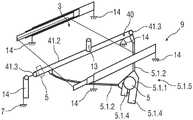
图13示出了座椅组件100的另一个实施例的示意图,该座椅组件100具有可自由调节座椅壳体2,该座椅壳体2具有自锁驱动单元5。FIG. 13 shows a schematic view of another embodiment of a
座椅组件100尤其构造为浮动座椅。类似于座椅组件1,座椅壳体2包括座椅表面区域2.2和靠背区域2.1以及基座元件3,座椅壳体2可调节地设置在基座元件3上。The
此外,座椅组件100包括用于相对于基座元件3调节座椅壳体2的调节单元40。此外,座椅组件100包括至少一个自锁驱动单元5。Furthermore, the
驱动单元5被构造为以自锁方式锁定基座元件3和座椅壳体2,其中锁定可以通过由就坐在座椅壳体2中的乘员经由座椅壳体2引入调节单元40的力F(I)并且也通过经由驱动单元5引入调节单元40的力F(5)来释放。The
因此,座椅壳体2可以通过自主调节、通过就坐在座椅壳体2中的人员的重心的变换和/或通过驱动单元5基于设置或激活调节模式的机动调节来调节。Thus, the
座椅壳体2被构造为单件或者可以例如包括相对于彼此固定地设置的座椅表面和靠背。座椅调节尤其通过就坐在座椅壳体2中的乘员的身体移动来实现。与先前已知的座椅调节装置相反,围绕一个或多个调节轴线的调节不是通过手动操作输入设施而是仅通过抵靠座椅壳体2,特别是座椅壳体2的座椅表面的乘员的重心或支撑中心的变换来实现。The
此外,座椅壳体2也可以在没有乘员的情况下进行调节。例如,座椅壳体2可以自动回到“正常”起始位置或座椅位置P1,或者更容易进入/离开的位置,特别是倾斜位置(未详细示出)。这种调节不仅可以在座椅或座椅壳体2是“空闲”时实现,而且如果乘员就坐在座椅壳体2中也可以实现。例如,存储位置,例如座椅位置P1,可以自动恢复。Furthermore, the
座椅组件100包括利用自锁原理的机械机动调节装置,使得不需要单独的锁定装置。The
为此,至少一个力传感器7设置在调节机构40和座椅基座9之间的力流F中。For this purpose, at least one
力传感器7被设置和构造成测量作用在调节单元40上的力F(1)或F(5)。为此,力传感器7联接到驱动单元5,使得当调节模式被激活并且力F(1)被施加到调节单元40时,例如由于座椅壳体2中的乘员的移动,驱动单元5的自锁被释放或至少减小。例如,为此,乘员已经通过激活单元10激活了座椅组件100的调节模式,使得由于座椅壳体2中乘员的重心或对应支撑发生变换,座椅壳体2相应地自动移动。The
控制单元6在此联接到驱动单元5、力传感器7和/或激活单元10。例如,控制单元6联接到力传感器7、驱动单元5和/或激活单元10用于信号发出和/或控制目的。The
在操作期间,例如通过输入单元11(例如开关或语音信号)和/或通过激活单元10确定乘员的调节命令。通过经由输入单元11输入调节命令或调节模式(例如通过语音命令或通过启动开关),特别是可以激活多种调节模式中的一种。可替代地或附加地,座椅组件100可以包括多个接触传感器12(这些接触传感器例如也用于检测座椅占用的传感器)作为激活单元10,以激活调节模式。可替代地或附加地,调节命令也可以用更少的传感器来确定,这些传感器检测在驱动单元5的靠近驱动装置的致动方向上的力分量。During operation, the occupant's adjustment command is determined, for example, by the input unit 11 (eg a switch or a voice signal) and/or by the
在可能的实施例中,浮动模式被激活,其中控制单元6被构造为在激活的浮动模式中移动座椅壳体2,使得这跟随就坐在座椅壳体2中的乘员的身体移动。这里,有是没有将座椅壳体2锁定在假定座椅位置P1中。In a possible embodiment, the floating mode is activated, wherein the
可替代地,可以激活调节模式,其中控制单元6被构造为在激活的调节模式下移动座椅壳体2,使得座椅壳体跟随就坐在座椅壳体2中的乘员的身体移动到达期望座椅位置P1中,并且其中座椅壳体2被锁定在期望座椅位置P1中,例如通过驱动单元5的自锁。Alternatively, an adjustment mode may be activated, wherein the
在另一替代例,可以激活驾驶舒适模式,其中控制单元6被构造为在激活的驾驶舒适模式下根据车辆的瞬时驾驶移动来调节座椅壳体2。In another alternative, a driving comfort mode may be activated, wherein the
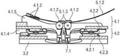
图13示出了调节单元40,其被构造为拉索机构41.1。例如,拉索机构41.1被构造为具有周向缆线41.2的弧形拉索装置。FIG. 13 shows the
驱动单元5包括至少一个齿轮马达单元。齿轮电机单元构造为带有马达5.1.1的自锁蜗轮5.1.4。蜗轮5.1.4的心轴通过鲍登缆线机构5.1.5、联接至拉索机构41.1。驱动单元5在此激活鲍登缆线机构5.1.5,其致动缆线41.2,该缆线41.2作用在为了移动目的而联接到座椅壳体2的承载部13上。The
为了移动目的,缆线41.2联接到自锁蜗轮5.1.4。例如,缆线41.2由两个偏转辊41.3保持,其由齿轮马达单元经由鲍登缆线机构5.1.5的鲍登缆线5.1.2驱动。此外,缆线41.2联接到承载部13,该承载部13附接到座椅壳体2。For moving purposes, the cable 41.2 is coupled to the self-locking worm gear 5.1.4. For example, the cable 41.2 is held by two deflection rollers 41.3, which are driven by the gear motor unit via the Bowden cable 5.1.2 of the Bowden cable mechanism 5.1.5. Furthermore, the cable 41 . 2 is coupled to the
如果承载部13基本上遵循座椅壳体2的弧形或弧形段并且缆线41.2搁置在弧形段上的座椅侧上,则调节单元40可以设计成非常坚硬,因为几乎不需要对缆线41.2进行长度调节。座椅壳体2通过缆线41.2和蜗轮5.1.4的自锁而锁定。为了调节座椅壳体2,可以通过激活马达5.1.1由马达来调节。If the
此外,座椅壳体2,特别是其相关联的调节单元40,和基座元件3和/或座椅基座9以及设置在其间的力传感器7主动联接使得作为合力,由就坐在座椅壳体2中的乘员引入座椅壳体2中的力F(I)作用于力传感器7上。Furthermore, the
为了测量由乘员引入座椅壳体2的力F(I),具有拉索机构14.1、偏转辊41.3和承载部13的调节单元40以及驱动单元5经由力传感器7抵靠座椅基座9,例如车辆地板支撑。通过将力传感器7设置在座椅基座9和座椅壳体2之间,该座椅壳体具有安装在诸如横杆元件3.1或承载部板3.2的结构支撑件上的诸如调节单元40、偏转辊41.3、承载部13和驱动单元5的部件,确保了缆线41.2的确保没有游隙所需的预张力不会叠加在力测量信号上,而是仅有来自调节命令的合力作用在力传感器7上。In order to measure the force F(I) introduced into the
为此,具有调节单元40或驱动单元5的作为承载部的基座元件3安装或设置在座椅基座9上,例如通过支撑点14(如图17所示)。为了确保该单一力传递点,将调节单元40安装在支撑点14上,使得在测量方向上的力分量受到尽可能小的影响。For this purpose, the
为此,可以提供对缆线41.2的引导。经由偏转辊41.3对缆线41.2的引导以及缆线41.2经由鲍登缆线5.1.2的移动进一步允许将驱动单元5分配至基座元件3,使得座椅壳体2承载更轻的重量。这也简化对马达5.1.1的供电。For this purpose, a guide for the cable 41.2 can be provided. The guiding of the cable 41.2 via the deflection rollers 41.3 and the movement of the cable 41.2 via the Bowden cable 5.1.2 further allow the distribution of the
为了使座椅10的座椅壳体2围绕竖直轴线Z旋转,可以提供单独的调节装置,例如图1至6中所示的上述调节单元4.2。用于围绕竖直轴线Z的调节的另一替代调节装置例如可以是由马达5.1.1和蜗轮形成的另一驱动单元5、5.1、5.2,其直接设置在座椅壳体2的枢轴点处而没有拉索机构41.1或沿座壳体2的弧形段以枢轴点为中心点进行设置,并联接至座椅壳体2,其中,另一个力传感器7作为用于切向作用力的传递元件设置在调节装置和基座元件3之间并且测量切向作用力(未详细示出)。In order to rotate the
此外,力阈值可以参数化并存储在控制单元6中,并在激活相应的调节机构4或40时考虑。由于可以对力阈值进行参数化,调节机构的时间行为参照图4或40,以及力施加和调节速度的转移因子,座椅1或10的调节行为可以被适配和修改。特别地,用于位置确定的其他传感器可以允许设置与位置相关的调节参数。Furthermore, the force threshold value can be parameterized and stored in the
此外,可以提供多个端部止动件16以用于限制用于座椅1和座椅100的座椅壳体2的调节移动。Furthermore, a plurality of end stops 16 may be provided for limiting adjustment movement of the
此外,可以为相应座椅1或10提供基于座椅环境传感器的困陷保护装置。Furthermore, a seat environment sensor-based entrapment protection device can be provided for the
此外,可以考虑,尤其是补偿环境影响,例如车辆加速或减速。为此,通过控制单元6确定车辆参数,例如车辆加速度或减速度,并相应地为相应的驱动单元5、5.1和/或5.2生成适合的控制信号。Furthermore, environmental influences, such as vehicle acceleration or deceleration, can be considered, in particular compensated. For this purpose, vehicle parameters, such as vehicle acceleration or deceleration, are determined by the
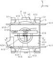
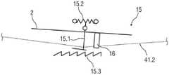
此外,座椅壳体2可设有过载保护装置15以吸收过载力,如图14和15所示。Furthermore, the
图14示出了过载保护装置15在空载状态下的示意图。FIG. 14 shows a schematic diagram of the
图15示出了过载保护器15在负载状态下的示意图。FIG. 15 shows a schematic diagram of the
过载保护装置15可防止必须通过缆线41.2和自锁驱动单元5或5.1、5.2消散的大力(例如由事故引起)。The
这种过载保护装置15可以例如由至少一个T形杆15.1形成,其脚部点通过特别是柔性铰链15.2(例如织物或弹簧铰链)可枢转地安装在座椅壳体2上。可替代地,也可以提供连接在一起的两个T形杆15.1(未详细示出)。Such an
缆线41.2,特别是钢缆,附接在T形杠15.1的横梁上方。对应于杆15.1的保护结构15.3,特别是制动或轮廓结构,例如相反锯齿结构,设置在杆15.1的横梁下方。A cable 41.2, in particular a steel cable, is attached above the beam of the T-bar 15.1. A protective structure 15.3 corresponding to the rod 15.1, in particular a braking or contoured structure, such as an inverse sawtooth structure, is provided below the beam of the rod 15.1.
在图15所示的空载状态下,横梁置于保护结构15.3上方,使得可以调节座椅壳体2。In the unloaded state shown in Fig. 15, the cross member is placed above the protective structure 15.3 so that the
如果引入过大力,则杆15.1的横梁与保护结构15.3接合,使得阻碍对座椅壳体2的调节。If excessive force is introduced, the beam of the rod 15.1 engages with the protective structure 15.3 so that adjustment of the
此外,可以提供端部止动件16以用于限制座椅壳体2的调节移动。Furthermore, end stops 16 may be provided for limiting adjustment movement of the
图16示出了调节机构40的透视图,其具有分配至基座元件3并通过支撑点14安装的调节单元41和联接的驱动单元5。FIG. 16 shows a perspective view of the
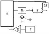
图17示意性地示出了控制单元6、力传感器7和驱动单元5用于信号发出和控制目的的联接的实施例。Figure 17 schematically shows an embodiment of the coupling of the
来自力传感器7的信号通过测量放大器17放大并提供给控制单元6以产生驱动单元5的驱动信号。驱动单元5的驱动信号通过桥式电路18,特别是电子H桥电路5.1.1提供以用于激活马达5.1.1。The signal from the
为了控制马达5.1.1,另外测量信号可以通过电流计19和马达传感器20,特别是霍尔效应传感器返回到控制单元6,以用于控制马达5.1.1。In order to control the motor 5.1.1, additionally the measurement signal can be returned to the
附图标记列表List of reference signs
1,100 座椅组件1,100 Seat Components
2 座椅、座椅壳体2 Seat, seat shell
2.1 靠背区域2.1 Backrest area
2.2 座椅表面区域2.2 Seat surface area
2.3 承载部2.3 Bearing part
3 基座元件3 Base element
3.1 横杆元件3.1 Crossbar elements
3.2 承载部板3.2 Bearing plate
3.2.1 通道开口3.2.1 Channel opening
4,4.1,4.2,40 调节单元4,4.1,4.2,40 Adjustment unit
4.1.1 轨道4.1.1 Track
4.1.2 辊子4.1.2 Rollers
4.1.3 端部止动件4.1.3 End stops
4.1.4 承载部元件4.1.4 Carrier element
4.1.5 引导轨道4.1.5 Guide rail
4.1.6 通道开口4.1.6 Channel opening
4.2.1 环形轨道4.2.1 Circular track
4.2.2 上环形轨道4.2.2 Upper circular track
4.2.3 下环形轨道4.2.3 Lower circular track
4.2.4 内环开口4.2.4 Inner ring opening
41.1 拉索机构41.1 Cable mechanism
41.2 缆线41.2 Cables
41.3 偏转辊41.3 Deflection rollers
5 驱动单元5 drive unit
5.1、5.2 驱动单元5.1, 5.2 Drive unit
5.1.1 马达5.1.1 Motor
5.1.2 鲍登缆线5.1.2 Bowden cable
5.1.3 力传递元件5.1.3 Force transmission elements
5.1.4 蜗轮5.1.4 Worm gear
5.1.5 鲍登缆线机构5.1.5 Bowden cable mechanism
5.2.1 马达5.2.1 Motor
5.2.2 鲍登缆线5.2.2 Bowden cable
6 控制单元6 Control unit
7.1,7.2,7 力传感器7.1,7.2,7 Force sensor
8 长度调节单元8 length adjustment unit
9 座椅基座9 Seat base
10 激活单元10 Activate cells
11 输入单元11 Input unit
12 接触传感器12 Contact sensor
13 承载部13 Bearing part
14 支撑点14 support points
15 过载保护装置15 Overload protection device
15.1 杆15.1 Pole
15.2 铰链15.2 Hinge
15.3 保护结构15.3 Protective structures
16 端部止动件16 End stop
17 测量放大器17 Measuring amplifier
18 桥电路18 bridge circuit
19 电流计19 Galvanometer
20 马达传感器20 Motor sensor
F 力流F force flow
F(I) 乘员引入的力F(I) Occupant induced force
F(5) 驱动单元引入的力F(5) Force introduced by drive unit
P1 设计或座椅位置P1 design or seating position
T1,T2 平移自由度T1,T2 translational degrees of freedom
R1、R2、R3旋转自由度R1, R2, R3 rotational degrees of freedom
X 纵向轴线X longitudinal axis
Y 横向轴线Y transverse axis
Z 竖直轴线Z vertical axis
x 纵向方向x portrait orientation
Claims (15)
Applications Claiming Priority (3)
| Application Number | Priority Date | Filing Date | Title |
|---|---|---|---|
| DE102019213665 | 2019-09-09 | ||
| DE102019213665.6 | 2019-09-09 | ||
| PCT/EP2020/075198WO2021048206A1 (en) | 2019-09-09 | 2020-09-09 | Seat assembly |
Publications (2)
| Publication Number | Publication Date |
|---|---|
| CN114650929Atrue CN114650929A (en) | 2022-06-21 |
| CN114650929B CN114650929B (en) | 2025-01-07 |
Family
ID=72517226
Family Applications (1)
| Application Number | Title | Priority Date | Filing Date |
|---|---|---|---|
| CN202080062876.2AActiveCN114650929B (en) | 2019-09-09 | 2020-09-09 | Seat assembly |
Country Status (4)
| Country | Link |
|---|---|
| US (1) | US12162379B2 (en) |
| EP (1) | EP4028283B1 (en) |
| CN (1) | CN114650929B (en) |
| WO (1) | WO2021048206A1 (en) |
Families Citing this family (7)
| Publication number | Priority date | Publication date | Assignee | Title |
|---|---|---|---|---|
| AT522485B1 (en)* | 2019-04-26 | 2020-12-15 | Margarethe Zenzmaier Cornelia | Body positioning device |
| US12005813B2 (en)* | 2019-05-03 | 2024-06-11 | Magna Seating Inc. | Long rail assembly with triple rail configuration |
| US12096863B2 (en)* | 2020-08-31 | 2024-09-24 | University of Pittsburg—Of the Commonweath System of Higher Education | Access system |
| WO2022145192A1 (en)* | 2020-12-28 | 2022-07-07 | テイ・エス テック株式会社 | Seat experiencing system |
| CN114148224A (en)* | 2021-11-03 | 2022-03-08 | 浙江吉利控股集团有限公司 | Seat and car |
| US12384280B2 (en) | 2022-10-11 | 2025-08-12 | B/E Aerospace, Inc. | Device for constraining actuator motion during a dynamic event |
| DE102023103253A1 (en)* | 2023-02-10 | 2024-08-14 | Audi Aktiengesellschaft | Simulation seat and simulation system |
Citations (18)
| Publication number | Priority date | Publication date | Assignee | Title |
|---|---|---|---|---|
| US20020024257A1 (en)* | 2000-01-11 | 2002-02-28 | Toyota Jidosha Kabushiki Kaisha | Apparatus and method for detecting a child seat |
| US20040164218A1 (en)* | 2003-02-12 | 2004-08-26 | Tachi-S Co., Ltd. | Slide device for automotive seat |
| US20050125106A1 (en)* | 2003-10-22 | 2005-06-09 | Wilfried Beneker | Cockpit of an automotive vehicle with a steering wheel and an adjustable seat |
| CN102765334A (en)* | 2011-05-06 | 2012-11-07 | 李尔公司 | Vehicle seat fold mechanism |
| CN103079877A (en)* | 2010-10-21 | 2013-05-01 | 凯波有限责任两合公司 | Longitudinal adjustor for a vehicle seat |
| CN103547479A (en)* | 2011-05-25 | 2014-01-29 | 爱信精机株式会社 | Vehicle seat device |
| CN105636823A (en)* | 2013-10-16 | 2016-06-01 | 约翰逊控制元件有限两合公司 | Easy-entry system and vehicle seat with an integrated easy-entry system |
| US20160167788A1 (en)* | 2013-07-03 | 2016-06-16 | Lufthansa Technik Ag | Airplane Seat With an Adjusting Device |
| CN106132768A (en)* | 2014-03-26 | 2016-11-16 | 佛吉亚汽车座椅有限责任公司 | Seat |
| CN106232421A (en)* | 2014-03-26 | 2016-12-14 | 佛吉亚汽车座椅有限责任公司 | There is the seat of computer-controlled memory lock |
| CN106335408A (en)* | 2016-10-25 | 2017-01-18 | 辽宁工程技术大学 | Adaptive Adjusting System for Automobile Driver Seat |
| CN106573554A (en)* | 2014-07-25 | 2017-04-19 | 佛吉亚汽车座椅公司 | Vehicle seat and method for adjusting a vehicle seat |
| CN108366674A (en)* | 2015-10-21 | 2018-08-03 | 努尼股份公司 | Seat unit for wearable posture assisting device |
| CN108688519A (en)* | 2017-04-10 | 2018-10-23 | 本田技研工业株式会社 | Seat unit |
| CN110023136A (en)* | 2016-09-30 | 2019-07-16 | 安道拓卢森堡控股有限公司 | Seat with backrest and headrest |
| US20190359087A1 (en)* | 2016-09-08 | 2019-11-28 | Shanghai Yanfeng Jinqiao Automotive Trim Systems Co. Ltd. | Seat assembly and configuration for a vehicle interior |
| WO2021048173A1 (en)* | 2019-09-09 | 2021-03-18 | Adient Engineering and IP GmbH | Seat assembly with anti-collision device |
| US20210213855A1 (en)* | 2018-04-04 | 2021-07-15 | Adient Engineering and IP GmbH | Floating seat |
Family Cites Families (10)
| Publication number | Priority date | Publication date | Assignee | Title |
|---|---|---|---|---|
| DE4429405A1 (en)* | 1994-08-09 | 1996-02-15 | Isringhausen Geb | Vibration-supported vehicle seat with an inclination and / or height adjustment of the seat |
| DE19624587A1 (en)* | 1996-06-20 | 1998-01-22 | Lear Corp | Seat |
| US9428088B1 (en)* | 2008-01-23 | 2016-08-30 | Arjuna Indraeswaran Rajasingham | Vehicle occupant support |
| DE10138893C1 (en)* | 2001-08-08 | 2003-04-17 | Faurecia Autositze Gmbh & Co | Pair of seat rails for manually longitudinally adjustable motor vehicle seats |
| DE10141875A1 (en)* | 2001-08-28 | 2003-03-20 | Lear Corp World Headquarters S | Car seat is mounted on rails which slide on floor rails, frame which supports seat cushion being connected to seat rails by swiveling arms, allowing position of cushion to be independently adjusted |
| DE102005008895A1 (en)* | 2005-02-26 | 2006-09-07 | Recaro Aircraft Seating Gmbh & Co. Kg | Passenger seat, in particular passenger seat |
| FR2916184B1 (en)* | 2007-05-15 | 2009-12-11 | Astrium Sas | VEHICLE SEAT AND SPACE VEHICLE EQUIPPED WITH THIS SEAT. |
| DE102014201633B4 (en)* | 2014-01-30 | 2023-07-20 | Bayerische Motoren Werke Aktiengesellschaft | Adjustment system for a seat and seat |
| US10245987B2 (en)* | 2016-12-22 | 2019-04-02 | GM Global Technology Operations LLC | Active vehicle seat architecture for inertial compensation in motor vehicles |
| DE102017221987A1 (en)* | 2017-12-06 | 2019-06-06 | Robert Bosch Gmbh | seating unit |
- 2020
- 2020-09-09EPEP20772013.7Apatent/EP4028283B1/enactiveActive
- 2020-09-09CNCN202080062876.2Apatent/CN114650929B/enactiveActive
- 2020-09-09USUS17/753,566patent/US12162379B2/enactiveActive
- 2020-09-09WOPCT/EP2020/075198patent/WO2021048206A1/ennot_activeCeased
Patent Citations (18)
| Publication number | Priority date | Publication date | Assignee | Title |
|---|---|---|---|---|
| US20020024257A1 (en)* | 2000-01-11 | 2002-02-28 | Toyota Jidosha Kabushiki Kaisha | Apparatus and method for detecting a child seat |
| US20040164218A1 (en)* | 2003-02-12 | 2004-08-26 | Tachi-S Co., Ltd. | Slide device for automotive seat |
| US20050125106A1 (en)* | 2003-10-22 | 2005-06-09 | Wilfried Beneker | Cockpit of an automotive vehicle with a steering wheel and an adjustable seat |
| CN103079877A (en)* | 2010-10-21 | 2013-05-01 | 凯波有限责任两合公司 | Longitudinal adjustor for a vehicle seat |
| CN102765334A (en)* | 2011-05-06 | 2012-11-07 | 李尔公司 | Vehicle seat fold mechanism |
| CN103547479A (en)* | 2011-05-25 | 2014-01-29 | 爱信精机株式会社 | Vehicle seat device |
| US20160167788A1 (en)* | 2013-07-03 | 2016-06-16 | Lufthansa Technik Ag | Airplane Seat With an Adjusting Device |
| CN105636823A (en)* | 2013-10-16 | 2016-06-01 | 约翰逊控制元件有限两合公司 | Easy-entry system and vehicle seat with an integrated easy-entry system |
| CN106132768A (en)* | 2014-03-26 | 2016-11-16 | 佛吉亚汽车座椅有限责任公司 | Seat |
| CN106232421A (en)* | 2014-03-26 | 2016-12-14 | 佛吉亚汽车座椅有限责任公司 | There is the seat of computer-controlled memory lock |
| CN106573554A (en)* | 2014-07-25 | 2017-04-19 | 佛吉亚汽车座椅公司 | Vehicle seat and method for adjusting a vehicle seat |
| CN108366674A (en)* | 2015-10-21 | 2018-08-03 | 努尼股份公司 | Seat unit for wearable posture assisting device |
| US20190359087A1 (en)* | 2016-09-08 | 2019-11-28 | Shanghai Yanfeng Jinqiao Automotive Trim Systems Co. Ltd. | Seat assembly and configuration for a vehicle interior |
| CN110023136A (en)* | 2016-09-30 | 2019-07-16 | 安道拓卢森堡控股有限公司 | Seat with backrest and headrest |
| CN106335408A (en)* | 2016-10-25 | 2017-01-18 | 辽宁工程技术大学 | Adaptive Adjusting System for Automobile Driver Seat |
| CN108688519A (en)* | 2017-04-10 | 2018-10-23 | 本田技研工业株式会社 | Seat unit |
| US20210213855A1 (en)* | 2018-04-04 | 2021-07-15 | Adient Engineering and IP GmbH | Floating seat |
| WO2021048173A1 (en)* | 2019-09-09 | 2021-03-18 | Adient Engineering and IP GmbH | Seat assembly with anti-collision device |
Non-Patent Citations (2)
| Title |
|---|
| 王豪清;汪洋;童宏拓;王祝兵;冯琛;钱俊;: "具有自适应靠背的无外界动力座椅设计研究", 家具与室内装饰, no. 04, 5 April 2016 (2016-04-05)* |
| 罗仕鉴;何基;王健;: "面向舒适性的自适应自动调节座椅底盘设计", 机械设计, no. 11, 20 November 2013 (2013-11-20)* |
Also Published As
| Publication number | Publication date |
|---|---|
| CN114650929B (en) | 2025-01-07 |
| EP4028283A1 (en) | 2022-07-20 |
| US20220371475A1 (en) | 2022-11-24 |
| US12162379B2 (en) | 2024-12-10 |
| WO2021048206A1 (en) | 2021-03-18 |
| EP4028283B1 (en) | 2023-11-08 |
Similar Documents
| Publication | Publication Date | Title |
|---|---|---|
| CN114650929A (en) | seat assembly | |
| US5340185A (en) | Vehicle safety seat having a raisable front edge | |
| CN101513849B (en) | Back support mechanism for vehicle seat | |
| US11458874B2 (en) | Vehicle seat | |
| CN105667353B (en) | reclining seat | |
| CN108725280A (en) | Handrail module for automotive seat | |
| KR20180108955A (en) | Seat position adjustment apparatus for vehicle | |
| US20150375647A1 (en) | Vehicle seat, in particular for a motor vehicle | |
| CN110582333B (en) | Passenger restraint devices for rides | |
| CN113165745B (en) | Reversible seat assembly | |
| JPH06502368A (en) | Seat assembly and method for reducing injury to seat occupants | |
| CN111204268A (en) | Vehicle and seat thereof | |
| KR102411246B1 (en) | Seat-back having Shoulder Adjuster | |
| JP3417868B2 (en) | Aircraft seating equipment | |
| JP7423948B2 (en) | Armrest device for seating seats | |
| CN214607186U (en) | Automobile with variable back row seats | |
| KR102338310B1 (en) | Seat for vehicle | |
| JP4622782B2 (en) | Sheet structure | |
| JPH0832512B2 (en) | Position control device for airbag seats | |
| JP2000085424A (en) | Vehicle seat | |
| KR100210150B1 (en) | Vehicle seat control device | |
| CN222554775U (en) | Seat adjustment systems and vehicles | |
| JP7449756B2 (en) | seat equipment | |
| CN119705523A (en) | Safety seat and high-speed train | |
| JP6584077B2 (en) | Bucket seat structure and passenger seat with adjustable position |
Legal Events
| Date | Code | Title | Description |
|---|---|---|---|
| PB01 | Publication | ||
| PB01 | Publication | ||
| SE01 | Entry into force of request for substantive examination | ||
| SE01 | Entry into force of request for substantive examination | ||
| GR01 | Patent grant | ||
| GR01 | Patent grant |